1
µC/ USB Device
TM
Universal Serial Bus Device Stack
User’s Manual
Weston, FL 33326
µC/USB Device User's Manual
1. uC-USB-Device User Manual . . . . . . . . . . . . . . . . . . . . . . . . . . . . . . . . . . . . . . . . . . . . . . . . . . . . . . . . . . . .
1.1 About USB . . . . . . . . . . . . . . . . . . . . . . . . . . . . . . . . . . . . . . . . . . . . . . . . . . . . . . . . . . . . . . . . . . . . . . .
1.1.1 Introduction . . . . . . . . . . . . . . . . . . . . . . . . . . . . . . . . . . . . . . . . . . . . . . . . . . . . . . . . . . . . . . . . . .
1.1.2 Data Flow Model . . . . . . . . . . . . . . . . . . . . . . . . . . . . . . . . . . . . . . . . . . . . . . . . . . . . . . . . . . . . . .
1.1.3 Physical Interface and Power Management . . . . . . . . . . . . . . . . . . . . . . . . . . . . . . . . . . . . . . . . . .
1.1.4 Device Structure and Enumeration . . . . . . . . . . . . . . . . . . . . . . . . . . . . . . . . . . . . . . . . . . . . . . . .
1.2 Getting Started . . . . . . . . . . . . . . . . . . . . . . . . . . . . . . . . . . . . . . . . . . . . . . . . . . . . . . . . . . . . . . . . . . . .
1.2.1 Installing the USB Device Stack . . . . . . . . . . . . . . . . . . . . . . . . . . . . . . . . . . . . . . . . . . . . . . . . . .
1.2.2 Building the Sample Application . . . . . . . . . . . . . . . . . . . . . . . . . . . . . . . . . . . . . . . . . . . . . . . . . .
1.2.3 Running the Sample Application . . . . . . . . . . . . . . . . . . . . . . . . . . . . . . . . . . . . . . . . . . . . . . . . . .
1.3 Host Operating Systems . . . . . . . . . . . . . . . . . . . . . . . . . . . . . . . . . . . . . . . . . . . . . . . . . . . . . . . . . . . . .
1.3.1 Microsoft Windows . . . . . . . . . . . . . . . . . . . . . . . . . . . . . . . . . . . . . . . . . . . . . . . . . . . . . . . . . . . .
1.4 Architecture . . . . . . . . . . . . . . . . . . . . . . . . . . . . . . . . . . . . . . . . . . . . . . . . . . . . . . . . . . . . . . . . . . . . . .
1.4.1 Porting uCUSB-Device to your RTOS . . . . . . . . . . . . . . . . . . . . . . . . . . . . . . . . . . . . . . . . . . . . .
1.4.2 Task Model . . . . . . . . . . . . . . . . . . . . . . . . . . . . . . . . . . . . . . . . . . . . . . . . . . . . . . . . . . . . . . . . . . .
1.5 Configuration . . . . . . . . . . . . . . . . . . . . . . . . . . . . . . . . . . . . . . . . . . . . . . . . . . . . . . . . . . . . . . . . . . . . .
1.5.1 Static Stack Configuration . . . . . . . . . . . . . . . . . . . . . . . . . . . . . . . . . . . . . . . . . . . . . . . . . . . . . . .
1.5.2 Application Specific Configuration . . . . . . . . . . . . . . . . . . . . . . . . . . . . . . . . . . . . . . . . . . . . . . . .
1.5.3 Device and Device Controller Driver Configuration . . . . . . . . . . . . . . . . . . . . . . . . . . . . . . . . . . .
1.5.4 Configuration Examples . . . . . . . . . . . . . . . . . . . . . . . . . . . . . . . . . . . . . . . . . . . . . . . . . . . . . . . . .
1.6 Device Driver Guide . . . . . . . . . . . . . . . . . . . . . . . . . . . . . . . . . . . . . . . . . . . . . . . . . . . . . . . . . . . . . . . .
1.6.1 General Information . . . . . . . . . . . . . . . . . . . . . . . . . . . . . . . . . . . . . . . . . . . . . . . . . . . . . . . . . . . .
1.6.2 Interrupt Handling . . . . . . . . . . . . . . . . . . . . . . . . . . . . . . . . . . . . . . . . . . . . . . . . . . . . . . . . . . . . .
1.6.3 Device Configuration . . . . . . . . . . . . . . . . . . . . . . . . . . . . . . . . . . . . . . . . . . . . . . . . . . . . . . . . . . .
1.6.4 USB Device Driver Functional Model . . . . . . . . . . . . . . . . . . . . . . . . . . . . . . . . . . . . . . . . . . . . . .
1.7 USB Classes . . . . . . . . . . . . . . . . . . . . . . . . . . . . . . . . . . . . . . . . . . . . . . . . . . . . . . . . . . . . . . . . . . . . . .
1.7.1 Class Instance Concept . . . . . . . . . . . . . . . . . . . . . . . . . . . . . . . . . . . . . . . . . . . . . . . . . . . . . . . . . .
1.7.2 Class Instance Structures . . . . . . . . . . . . . . . . . . . . . . . . . . . . . . . . . . . . . . . . . . . . . . . . . . . . . . . .
1.7.3 Class and Core Layers Interaction Through Callbacks . . . . . . . . . . . . . . . . . . . . . . . . . . . . . . . . .
1.8 Audio Class . . . . . . . . . . . . . . . . . . . . . . . . . . . . . . . . . . . . . . . . . . . . . . . . . . . . . . . . . . . . . . . . . . . . . . .
1.8.1 Audio Class Overview . . . . . . . . . . . . . . . . . . . . . . . . . . . . . . . . . . . . . . . . . . . . . . . . . . . . . . . . . .
1.8.2 Audio Class Features Support . . . . . . . . . . . . . . . . . . . . . . . . . . . . . . . . . . . . . . . . . . . . . . . . . . . .
1.8.3 Audio Class Architecture . . . . . . . . . . . . . . . . . . . . . . . . . . . . . . . . . . . . . . . . . . . . . . . . . . . . . . . .
1.8.4 Audio Class Configuration . . . . . . . . . . . . . . . . . . . . . . . . . . . . . . . . . . . . . . . . . . . . . . . . . . . . . . .
1.8.4.1 Audio Topology Configuration . . . . . . . . . . . . . . . . . . . . . . . . . . . . . . . . . . . . . . . . . . . . . . .
1.8.4.2 Audio Class Instance Configuration . . . . . . . . . . . . . . . . . . . . . . . . . . . . . . . . . . . . . . . . . . .
1.8.4.3 Audio Statistics . . . . . . . . . . . . . . . . . . . . . . . . . . . . . . . . . . . . . . . . . . . . . . . . . . . . . . . . . . .
1.8.5 Audio Class Stream Data Flow . . . . . . . . . . . . . . . . . . . . . . . . . . . . . . . . . . . . . . . . . . . . . . . . . . .
1.8.6 Using the Audio Class Demo Application . . . . . . . . . . . . . . . . . . . . . . . . . . . . . . . . . . . . . . . . . . .
1.8.7 Audio Class Configuration Guidelines . . . . . . . . . . . . . . . . . . . . . . . . . . . . . . . . . . . . . . . . . . . . .
1.8.8 Audio Peripheral Driver Guide . . . . . . . . . . . . . . . . . . . . . . . . . . . . . . . . . . . . . . . . . . . . . . . . . . .
1.8.9 Porting the Audio Class to an RTOS . . . . . . . . . . . . . . . . . . . . . . . . . . . . . . . . . . . . . . . . . . . . . . .
4
5
6
9
14
15
18
19
22
33
38
39
46
47
51
60
61
76
78
79
84
85
90
95
99
111
112
122
125
128
129
139
142
145
150
165
173
181
199
211
216
231
1.9 Communications Device Class . . . . . . . . . . . . . . . . . . . . . . . . . . . . . . . . . . . . . . . . . . . . . . . . . . . . . . . .
1.9.1 CDC Class Overview . . . . . . . . . . . . . . . . . . . . . . . . . . . . . . . . . . . . . . . . . . . . . . . . . . . . . . . . . . .
1.9.2 CDC Architecture . . . . . . . . . . . . . . . . . . . . . . . . . . . . . . . . . . . . . . . . . . . . . . . . . . . . . . . . . . . . . .
1.9.3 CDC Configuration . . . . . . . . . . . . . . . . . . . . . . . . . . . . . . . . . . . . . . . . . . . . . . . . . . . . . . . . . . . .
1.9.4 ACM Subclass . . . . . . . . . . . . . . . . . . . . . . . . . . . . . . . . . . . . . . . . . . . . . . . . . . . . . . . . . . . . . . . .
1.9.4.1 Using the ACM Subclass Demo Application . . . . . . . . . . . . . . . . . . . . . . . . . . . . . . . . . . . .
1.10 CDC Ethernet Emulation Model Subclass . . . . . . . . . . . . . . . . . . . . . . . . . . . . . . . . . . . . . . . . . . . . . .
1.10.1 CDC EEM Subclass Overview . . . . . . . . . . . . . . . . . . . . . . . . . . . . . . . . . . . . . . . . . . . . . . . . . .
1.10.2 CDC EEM Subclass Architecture . . . . . . . . . . . . . . . . . . . . . . . . . . . . . . . . . . . . . . . . . . . . . . . .
1.10.3 CDC EEM Subclass Configuration . . . . . . . . . . . . . . . . . . . . . . . . . . . . . . . . . . . . . . . . . . . . . . .
1.10.4 CDC EEM Demo Application . . . . . . . . . . . . . . . . . . . . . . . . . . . . . . . . . . . . . . . . . . . . . . . . . . .
1.11 Human Interface Device Class . . . . . . . . . . . . . . . . . . . . . . . . . . . . . . . . . . . . . . . . . . . . . . . . . . . . . . .
1.11.1 HID Class Overview . . . . . . . . . . . . . . . . . . . . . . . . . . . . . . . . . . . . . . . . . . . . . . . . . . . . . . . . . .
1.11.2 HID Class Architecture . . . . . . . . . . . . . . . . . . . . . . . . . . . . . . . . . . . . . . . . . . . . . . . . . . . . . . . .
1.11.3 HID Class Configuration . . . . . . . . . . . . . . . . . . . . . . . . . . . . . . . . . . . . . . . . . . . . . . . . . . . . . . .
1.11.4 Using the HID Class Demo Application . . . . . . . . . . . . . . . . . . . . . . . . . . . . . . . . . . . . . . . . . . .
1.11.5 Porting the HID Class to an RTOS . . . . . . . . . . . . . . . . . . . . . . . . . . . . . . . . . . . . . . . . . . . . . . .
1.11.6 HID Periodic Input Reports Task . . . . . . . . . . . . . . . . . . . . . . . . . . . . . . . . . . . . . . . . . . . . . . . . .
1.12 Mass Storage Class . . . . . . . . . . . . . . . . . . . . . . . . . . . . . . . . . . . . . . . . . . . . . . . . . . . . . . . . . . . . . . . .
1.12.1 MSC Overview . . . . . . . . . . . . . . . . . . . . . . . . . . . . . . . . . . . . . . . . . . . . . . . . . . . . . . . . . . . . . . .
1.12.2 MSC Architecture . . . . . . . . . . . . . . . . . . . . . . . . . . . . . . . . . . . . . . . . . . . . . . . . . . . . . . . . . . . .
1.12.3 MSC RTOS Layer . . . . . . . . . . . . . . . . . . . . . . . . . . . . . . . . . . . . . . . . . . . . . . . . . . . . . . . . . . . .
1.12.4 MSC Configuration . . . . . . . . . . . . . . . . . . . . . . . . . . . . . . . . . . . . . . . . . . . . . . . . . . . . . . . . . . .
1.12.5 Using the MSC Demo Application . . . . . . . . . . . . . . . . . . . . . . . . . . . . . . . . . . . . . . . . . . . . . . .
1.12.6 Porting MSC to a Storage Layer . . . . . . . . . . . . . . . . . . . . . . . . . . . . . . . . . . . . . . . . . . . . . . . . .
1.12.7 Porting MSC to an RTOS . . . . . . . . . . . . . . . . . . . . . . . . . . . . . . . . . . . . . . . . . . . . . . . . . . . . . . .
1.13 Personal Healthcare Device Class . . . . . . . . . . . . . . . . . . . . . . . . . . . . . . . . . . . . . . . . . . . . . . . . . . . .
1.13.1 PHDC Overview . . . . . . . . . . . . . . . . . . . . . . . . . . . . . . . . . . . . . . . . . . . . . . . . . . . . . . . . . . . . .
1.13.2 PHDC Configuration . . . . . . . . . . . . . . . . . . . . . . . . . . . . . . . . . . . . . . . . . . . . . . . . . . . . . . . . . .
1.13.3 PHDC Class Instance Communication . . . . . . . . . . . . . . . . . . . . . . . . . . . . . . . . . . . . . . . . . . . .
1.13.4 PHDC RTOS QoS-based scheduler . . . . . . . . . . . . . . . . . . . . . . . . . . . . . . . . . . . . . . . . . . . . . . .
1.13.5 Using the PHDC Demo Application . . . . . . . . . . . . . . . . . . . . . . . . . . . . . . . . . . . . . . . . . . . . . .
1.13.6 Porting PHDC to an RTOS . . . . . . . . . . . . . . . . . . . . . . . . . . . . . . . . . . . . . . . . . . . . . . . . . . . . .
1.14 Vendor Class . . . . . . . . . . . . . . . . . . . . . . . . . . . . . . . . . . . . . . . . . . . . . . . . . . . . . . . . . . . . . . . . . . . . .
1.14.1 Vendor Class Overview . . . . . . . . . . . . . . . . . . . . . . . . . . . . . . . . . . . . . . . . . . . . . . . . . . . . . . . .
1.14.2 Vendor Class Configuration . . . . . . . . . . . . . . . . . . . . . . . . . . . . . . . . . . . . . . . . . . . . . . . . . . . . .
1.14.3 Vendor Class Instance Communication . . . . . . . . . . . . . . . . . . . . . . . . . . . . . . . . . . . . . . . . . . . .
1.14.4 USBDev_API . . . . . . . . . . . . . . . . . . . . . . . . . . . . . . . . . . . . . . . . . . . . . . . . . . . . . . . . . . . . . . . .
1.14.5 Using the Vendor Class Demo Application . . . . . . . . . . . . . . . . . . . . . . . . . . . . . . . . . . . . . . . . .
1.15 Debug and Trace . . . . . . . . . . . . . . . . . . . . . . . . . . . . . . . . . . . . . . . . . . . . . . . . . . . . . . . . . . . . . . . . . .
1.15.1 Using Debug Traces . . . . . . . . . . . . . . . . . . . . . . . . . . . . . . . . . . . . . . . . . . . . . . . . . . . . . . . . . . .
1.15.2 Handling Debug Events . . . . . . . . . . . . . . . . . . . . . . . . . . . . . . . . . . . . . . . . . . . . . . . . . . . . . . . .
1.16 Porting uC-USB-Device to your RTOS . . . . . . . . . . . . . . . . . . . . . . . . . . . . . . . . . . . . . . . . . . . . . . . .
233
235
238
240
242
250
256
257
259
262
269
271
272
279
280
291
297
299
301
302
306
312
314
319
325
326
327
328
332
337
341
345
349
350
351
353
357
366
373
383
384
386
388
1.16.1 Porting Overview . . . . . . . . . . . . . . . . . . . . . . . . . . . . . . . . . . . . . . . . . . . . . . . . . . . . . . . . . . . . .
1.16.2 Porting Modules to an RTOS . . . . . . . . . . . . . . . . . . . . . . . . . . . . . . . . . . . . . . . . . . . . . . . . . . . .
1.16.3 Core Layer RTOS Model . . . . . . . . . . . . . . . . . . . . . . . . . . . . . . . . . . . . . . . . . . . . . . . . . . . . . . .
1.16.4 Porting the Core Layer to an RTOS . . . . . . . . . . . . . . . . . . . . . . . . . . . . . . . . . . . . . . . . . . . . . . .
1.17 Test and Validation of uC-USB-Device . . . . . . . . . . . . . . . . . . . . . . . . . . . . . . . . . . . . . . . . . . . . . . . .
1.18 Troubleshooting . . . . . . . . . . . . . . . . . . . . . . . . . . . . . . . . . . . . . . . . . . . . . . . . . . . . . . . . . . . . . . . . . .
1.18.1 Built-in Statistics . . . . . . . . . . . . . . . . . . . . . . . . . . . . . . . . . . . . . . . . . . . . . . . . . . . . . . . . . . . . .
1.18.2 Error Codes and Solutions . . . . . . . . . . . . . . . . . . . . . . . . . . . . . . . . . . . . . . . . . . . . . . . . . . . . . .
uC-USB-Device User Manual
389
391
392
395
397
401
402
408
µC/USB Device User's Manual
uC-USB-Device User Manual
USB is likely the most successful communication interface in the history of computer systems,
and is the de-facto standard for connecting computer peripherals.
Micrium’s µC/USB-Device is a USB device stack designed specifically for embedded systems.
Built from the ground up with Micrium’s quality, scalability and reliability, it has gone through
a rigorous validation process to comply with the USB 2.0 specification.
The first section of this space, uC-USB-Device User Manual, describes the inner-workings of
USB and the way Micrium’s µC/USB-Device stack can be used to simplify USB development.
It also gives details about the various configuration values and their uses and a porting guide
for the core and all the classes. Information such as overview, configuration possibilities,
implementation details and examples of typical usage is also given for every available class.
The second section, µC/USB-Device Reference Manual, gives details about the various
functions that are available in the stack. The functions from the core and every class are
documented, to facilitate the development of any application.
The examples featured in this documentation space include USB devices with the most basic
functionality that will allow you to understand the USB concepts covered in the first part of the
space and at the same time, they provide a framework to quickly build devices such as:
Microphone, speaker or headset (Audio Class)
USB-to-serial adapter (Communications Device Class)
Mouse or keyboard (Human Interface Device Class)
Removable storage device (Mass Storage Class)
USB medical device (Personal Healthcare Device Class)
Custom device (Vendor Class)
Copyright 2015 Micrium Inc.
4
µC/USB Device User's Manual
About USB
This chapter presents a quick introduction to USB. The first section in this chapter introduces
the basic concepts of the USB specification Revision 2.0. The second section explores the data
flow model. The third section gives details about the device operation. Lastly, the fourth
section describes USB device logical organization.
The full protocol is described extensively in the USB Specification Revision 2.0 at
http://www.usb.org.
Copyright 2015 Micrium Inc.
5
µC/USB Device User's Manual
Introduction
The Universal Serial Bus (USB) is an industry standard maintained by the USB Implementers
Forum (USB-IF) for serial bus communication. The USB specification contains all the
information about the protocol such as the electrical signaling, the physical dimension of the
connector, the protocol layer, and other important aspects. USB provides several benefits
compared to other communication interfaces such as ease of use, low cost, low power
consumption and, fast and reliable data transfer.
Bus Topology
USB can connect a series of devices using a tiered star topology. The key elements in USB
topology are the host, hubs, and devices, as illustrated in Figure - USB Bus Topology in the
Introduction page. Each node in the illustration represents a USB hub or a USB device. At the
top level of the graph is the root hub, which is part of the host. There is only one host in the
system. The specification allows up to seven tiers and a maximum of five non-root hubs in any
path between the host and a device. Each tier must contain at least one hub except for the last
tier where only devices are present. Each USB device in the system has a unique address
assigned by the host through a process called enumeration (see section Enumeration for more
details on enumeration).
The host learns about the device capabilities during enumeration, which allows the host
operating system to load a specific driver for a particular USB device. The maximum number
of peripherals that can be attached to a host is 127, including the root hub.
Copyright 2015 Micrium Inc.
6
µC/USB Device User's Manual
Figure - USB Bus Topology
USB Host
The USB host communicates with the devices using a USB host controller. The host is
responsible for detecting and enumerating devices, managing bus access, performing error
checking, providing and managing power, and exchanging data with the devices.
USB Device
A USB device implements one or more USB functions where a function provides one specific
capability to the system. Examples of USB functions are keyboards, webcam, speakers, or a
mouse. The requirements of the USB functions are described in the USB class specification.
For example, keyboards and mice are implemented using the Human Interface Device (HID)
specification.
USB devices must also respond to requests from the host. For example, on power up, or when
a device is connected to the host, the host queries the device capabilities during enumeration,
using standard requests.
Copyright 2015 Micrium Inc.
7
µC/USB Device User's Manual
Copyright 2015 Micrium Inc.
8
µC/USB Device User's Manual
Data Flow Model
This section defines the elements involved in the transmission of data across USB.
Endpoint
Endpoints function as the point of origin or the point of reception for data. An endpoint is a
logical entity identified using an endpoint address. The endpoint address of a device is fixed,
and is assigned when the device is designed, as opposed to the device address, which is
assigned by the host dynamically during enumeration. An endpoint address consists of an
endpoint number field (0 to 15), and a direction bit that indicates if the endpoint sends data to
the host (IN) or receives data from the host (OUT). The maximum number of endpoints
allowed on a single device is 32.
Endpoints contain configurable characteristics that define the behavior of a USB device:
Bus access requirements
Bandwidth requirement
Error handling
Maximum packet size that the endpoint is able to send or receive
Transfer type
Direction in which data is sent and receive from the host
Endpoint Zero Requirement
Endpoint zero (also known as Default Endpoint) is a bi-directional endpoint used by the USB
host system to get information, and configure the device via standard requests. All devices
must implement an endpoint zero configured for control transfers (see section Control
Transfers for more information).
Copyright 2015 Micrium Inc.
9
µC/USB Device User's Manual
Pipes
A USB pipe is a logical association between an endpoint and a software structure in the USB
host software system. USB pipes are used to send data from the host software to the device’s
endpoints. A USB pipe is associated to a unique endpoint address, type of transfer, maximum
packet size, and interval for transfers.
The USB specification defines two types of pipes based on the communication mode:
Stream Pipes: Data carried over the pipe is unstructured.
Message Pipes: Data carried over the pipe has a defined structure.
Transfer Types
The USB specification requires a default control pipe for each device. A default control pipe
uses endpoint zero. The default control pipe is a bi-directional message pipe.
The USB specification defines four transfer types that match the bandwidth and services
requirements of the host and the device application using a specific pipe. Each USB transfer
encompasses one or more transactions that send data to and from the endpoint. The notion of
transactions is related to the maximum payload size defined by each endpoint type. That is,
when a transfer is greater than this maximum, it will be split into one or more transactions to
fulfill the action.
Control Transfers
Control transfers are used to configure and retrieve information about the device capabilities.
They are used by the host to send standard requests during and after enumeration. Standard
requests allow the host to learn about the device capabilities; for example, how many and
which functions the device contains. Control transfers are also used for class-specific and
vendor-specific requests.
A control transfer contains three stages: Setup, Data, and Status. These stages are listed in
Table - Control Transfer Stages in the Data Flow Model page.
Copyright 2015 Micrium Inc.
10
µC/USB Device User's Manual
Stage
Description
Setup
The Setup stage includes information about the request. This SETUP stage represents one transaction.
Data
The Data stage contains data associated with request. Some standard and class-specific request may not
require a Data stage. This stage is an IN or OUT directional transfer and the complete Data stage
represents one ore more transactions.
Status
The Status stage, representing one transaction, is used to report the success or failure of the transfer. The
direction of the Status stage is opposite to the direction of the Data stage. If the control transfer has no
Data stage, the Status stage always is from the device (IN).
Table - Control Transfer Stages
Bulk Transfers
Bulk transfers are intended for devices that exchange large amounts of data where the transfer
can take all of the available bus bandwidth. Bulk transfers are reliable, as error detection and
retransmission mechanisms are implemented in hardware to guarantee data integrity. However,
bulk transfers offer no guarantee on timing. Printers and mass storage devices are examples of
devices that use bulk transfers.
Interrupt Transfers
Interrupt transfers are designed to support devices with latency constrains. Devices using
interrupt transfers can schedule data at any time. Devices using interrupt transfer provide a
polling interval which determines when the scheduled data is transferred over the bus. Interrupt
transfers are typically used for event notifications.
Isochronous Transfers
Isochronous transfers are used by devices that require data delivery at a constant rate with a
certain degree of error-tolerance. Retransmission is not supported by isochronous transfers.
Audio and video devices use isochronous transfers.
USB Data Flow Model
Figure - USB Data Flow in the Data Flow Model page shows a graphical representation of the
data flow model.
Copyright 2015 Micrium Inc.
11
µC/USB Device User's Manual
Figure - USB Data Flow
(1)
The host software uses standard requests to query and configure the device using the
default pipe. The default pipe uses endpoint zero (EP0).
(2)
USB pipes allow associations between the host application and the device’s endpoints.
Host applications send and receive data through USB pipes.
(3)
The host controller is responsible for the transmission, reception, packing and unpacking
of data over the bus.
(4)
Data is transmitted via the physical media.
(5)
The device controller is responsible for the transmission, reception, packing and
unpacking of data over the bus. The USB controller informs the USB device software
layer about several events such as bus events and transfer events.
(6)
The device software layer responds to the standard request, and implements one or more
USB functions as specified in the USB class document.
Copyright 2015 Micrium Inc.
12
µC/USB Device User's Manual
Transfer Completion
The notion of transfer completion is only relevant for control, bulk and interrupt transfers as
isochronous transfers occur continuously and periodically by nature. In general, control, bulk
and interrupt endpoints must transmit data payload sizes that are less than or equal to the
endpoint’s maximum data payload size. When a transfer’s data payload is greater than the
maximum data payload size, the transfer is split into several transactions whose payload is
maximum-sized except the last transaction which contains the remaining data. A transfer is
deemed complete when:
The endpoint transfers exactly the amount of data expected.
The endpoint transfers a short packet, that is a packet with a payload size less than the
maximum.
The endpoint transfers a zero-length packet.
Copyright 2015 Micrium Inc.
13
µC/USB Device User's Manual
Physical Interface and Power Management
Physical Interface
USB transfers data and provides power using four-wire cables. The four wires are: Vbus, D+,
D- and Ground. Signaling occurs on the D+ and D- wires.
Speed
The USB 2.0 specification defines three different speeds.
Low Speed: 1.5 Mb/s
Full Speed: 12 Mb/s
High Speed: 480 Mb/s
Power Distribution
The host can supply power to USB devices that are directly connected to the host. USB devices
may also have their own power supplies. USB devices that use power from the cable are called
bus-powered devices. Bus-powered devices can draw a maximum of 500 mA from the host.
USB devices that have an alternative source of power are called self-powered devices.
Copyright 2015 Micrium Inc.
14
µC/USB Device User's Manual
Device Structure and Enumeration
Before the host application can communicate with a device, the host needs to understand the
capabilities of the device. This process takes place during device enumeration. After
enumeration, the host can assign and load a specific driver to allow communication between
the application and the device.
During enumeration, the host assigns an address to the device, reads descriptors from the
device, and selects a configuration that specifies power and interface requirements. In order for
the host to learn about the device’s capabilities, the device must provide information about
itself in the form of descriptors.
This section describes the device’s logical organization from the USB host’s point of view.
USB Device Structure
From the host’s point of view, USB devices are internally organized as a collection of
configurations, interfaces and endpoints.
Configuration
A USB configuration specifies the capabilities of a device. A configuration consists of a
collection of USB interfaces that implement one or more USB functions. Typically only one
configuration is required for a given device. However, the USB specification allows up to 255
different configurations. During enumeration, the host selects a configuration. Only one
configuration can be active at a time. The device uses a configuration descriptor to inform the
host about a specific configuration’s capabilities.
Interface
A USB interface or a group of interfaces provides information about a function or class
implemented by the device. An interface can contain multiple mutually exclusive settings
called alternate settings. The device uses an interface descriptor to inform the host about a
specific interface’s capabilities. Each interface descriptor contains a class, subclass, and
protocol codes defined by the USB-IF, and the number of endpoints required for a particular
class implementation.
Copyright 2015 Micrium Inc.
15
µC/USB Device User's Manual
Alternate Settings
Alternate settings are used by the device to specify mutually exclusive settings for each
interface. The default alternate settings contain the default settings of the device. The device
also uses an interface descriptor to inform the host about an interface’s alternate settings.
Endpoint
An interface requires a set of endpoints to communicate with the host. Each interface has
different requirements in terms of the number of endpoints, transfer type, direction, maximum
packet size, and maximum polling interval. The device sends an endpoint descriptor to notify
the host about endpoint capabilities.
Figure - USB Device Structure in the Device Structure and Enumeration page shows the
hierarchical organization of a USB device. Configurations are grouped based on the device’s
speed. A high-speed device might have a particular configuration in both high-speed and
low/full speed.
Figure - USB Device Structure
Copyright 2015 Micrium Inc.
16
µC/USB Device User's Manual
Device States
The USB 2.0 specification defines six different states and are listed in Table - USB Device
States in the Device Structure and Enumeration page.
Device States
Description
Attached
The device is in the Attached state when it is connected to the host or a hub port. The hub must
be connected to the host or to another hub.
Powered
A device is considered in the Powered state when it starts consuming power from the bus. Only
bus-powered devices use power from the host. Self-powered devices are in the Powered state
after port attachment.
Default
After the device has been powered, it should not respond to any request or transactions until it
receives a reset signal from the host. The device enters in the Default state when it receives a
reset signal from the host. In the Default state, the device responds to standard requests at the
default address 0.
Address
During enumeration, the host assigns a unique address to the device. When this occurs, the
device moves from the Default state to the Address state.
Configured
After the host assigns an address to the device, the host must select a configuration. After the
host selects a configuration, the device enters the Configured state. In this state, the device is
ready to communicate with the host applications.
Suspended
The device enters into Suspended state when no traffic has been seen over the bus for a specific
period of time. The device retains the address assigned by the host in the Suspended state. The
device returns to the previous state after traffic is present in the bus.
Table - USB Device States
Enumeration
Enumeration is the process where the host configures the device and learns about the device’s
capabilities. The host starts enumeration after the device is attached to one of the root or
external hub ports. The host learns about the device’s manufacturer, vendor/product IDs and
release versions by sending a Get Descriptor request to obtain the device descriptor and the
maximum packet size of the default pipe (control endpoint 0). Once that is done, the host
assigns a unique address to the device which will tell the device to only answer requests at this
unique address. Next, the host gets the capabilities of the device by a series of Get Descriptor
requests. The host iterates through all the available configurations to retrieve information about
number of interfaces in each configuration, interfaces classes, and endpoint parameters for
each interface and will lastly finish the enumeration process by selecting the most suitable
configuration.
Copyright 2015 Micrium Inc.
17
µC/USB Device User's Manual
Getting Started
This chapter gives you some insight into how to install and use the µC/USB-Device stack. The
following topics are explained in this chapter:
Prerequisites
Downloading the source code files
Installing the files
Building the sample application
Running the sample application
At the end of this chapter, you should be able to build and run your first USB application using
the µC/USB-Device stack.
Copyright 2015 Micrium Inc.
18
µC/USB Device User's Manual
Installing the USB Device Stack
Prerequisites
Before running your first application, you must ensure that you have the minimal set of
required tools and components:
Toolchain for your specific microcontroller.
Development board.
µC/USB-Device stack with the source code of at least one of the Micrium USB classes.
USB device controller driver compatible with your hardware for the µC/USB-Device stack.
Board support package (BSP) for your development board.
Example project for your selected RTOS (that is µC/OS-II or µC/OS-III).
If Micrium does not support your USB device controller or BSP, you will have to write your own
device driver. Refer to Device Driver Guide for more information on writing your own USB device
driver.
Downloading the Source Code
µC/USB-Device can be downloaded from the Micrium customer portal. The distribution
package includes the full source code and documentation. You can log into the Micrium
customer portal at the address below to begin your download (you must have a valid license to
gain access to the file):
http://micrium.com/customer-login/
µC/USB-Device depends on other modules, and you need to install all the required modules
before building your application. Depending on the availability of support for your hardware
platform, ports and drivers may or may not be available for download from the customer
Copyright 2015 Micrium Inc.
19
µC/USB Device User's Manual
portal. Table - µC/USB-Device Module Dependency in the Installing the USB Device Stack
page shows the module dependency for µC/USB-Device.
Module Name
Required
Note(s)
µC/USB-Device Core
YES
Hardware independent USB stack.
µC/USB-Device Driver
YES
USB device controller driver. Available only if Micrium supports your
controller, otherwise you have to develop it yourself.
µC/USB-Device Audio Class
Optional
Available only if you purchased the Audio class.
µC/USB-Device CDC ACM
Optional
Available only if you purchased the Communication Device Class
(CDC) with the Abstract Control Model (ACM) subclass.
µC/USB-Device CDC EEM
Optional
Available only if you purchased the Communication Device Class
(CDC) Ethernet Emulation Model (EEM) subclass.
µC/USB-Device HID Class
Optional
Available only if you purchased the Human Interface Device (HID)
class.
µC/USB-Device MSC
Optional
Available only if you purchased the Mass Storage Class (MSC).
µC/USB-Device PHDC
Optional
Available only if you purchased the Personal Healthcare Device Class
(PHDC).
µC/USB-Device Vendor Class
Optional
Available only if you purchased the Vendor class.
µC/CPU Core
YES
µC/CPU Port
YES
Available only if Micrium has support for your processor architecture.
µC/LIB Core
YES
Micrium run-time library.
µC/LIB Port
Optional
Available only if Micrium has support for your processor architecture.
µC/OS-II Core
Optional
Available only if your application is using µC/OS-II.
µC/OS-II Port
Optional
Available only if Micrium has support for your processor architecture.
µC/OS-III Core
Optional
Available only if your application is using µC/OS-III.
µC/OS-III Port
Optional
Available only if Micrium has support for your processor architecture.
Table - µC/USB-Device Module Dependency
Table - µC/USB-Device Module Dependency in the Installing the USB Device Stack
page indicates that all the µC/USB-Device classes are optional because there is no mandatory
class to purchase with the µC/USB-Device Core and Driver. The class to purchase will depend
on your needs. But don’t forget that you need a class to build a complete USB project. Table µC/USB-Device Module Dependency in the Installing the USB Device Stack page also
indicates that µC/OS-II and -III Core and Port are optional. Indeed, µC/USB-Device stack does
not assume a specific real-time operating system to work with, but it still requires one.
Copyright 2015 Micrium Inc.
20
µC/USB Device User's Manual
Installing the Files
Once all the distribution packages have been downloaded to your host machine, extract all the
files at the root of your C:\ drive for instance. The package may be extracted to any location.
After extracting all the files, the directory structure should look as illustrated in Figure Directory Tree for µC/USB-Device in the Installing the USB Device Stack page. In the
example, all Micrium products sub-folders shown in Figure - Directory Tree for
µC/USB-Device in the Installing the USB Device Stack page will be located in
C:\Micrium\Software\.
Figure - Directory Tree for µC/USB-Device
Copyright 2015 Micrium Inc.
21
µC/USB Device User's Manual
Building the Sample Application
This section describes all the steps required to build a USB-based application. The instructions
provided in this section are not intended for any particular toolchain, but instead are described
in a generic way that can be adapted to any toolchain.
The best way to start building a USB-based project is to start from an existing project. If you
are using µC/OS-II or µC/OS-III, Micrium provides example projects for multiple development
boards and compilers. If your target board is not listed on Micrium’s web site, you can
download an example project for a similar board or microcontroller.
The purpose of the sample project is to allow a host to enumerate your device. You will add a
USB class instance to both, full-speed and high-speed configurations (if both are supported by
your controller). Refer to the Class Instance Concept page for more details about the class
instance concept. After you have successfully completed and run the sample project, you can
use it as a starting point to run other USB class demos you may have purchased.
µC/USB-Device requires a Real-Time Operating System (RTOS). The following assumes that
you have a working example project running on µC/OS-II or µC/OS-III.
Understanding Micrium Examples
A Micrium example project is usually placed in the following directory structure.
\Micrium
\Software
\EvalBoards
\<manufacturer>
\<board_name>
\<compiler>
\<project name>
\*.*
Note that Micrium does not provide by default an example project with the µC/USB-Device
distribution package. Micrium examples are provided to customers in specific situations. If it
happens that you receive a Micrium example, the directory structure shown above is generally
used by Micrium. You may use a different directory structure to store the application and
toolchain projects files.
Copyright 2015 Micrium Inc.
22
µC/USB Device User's Manual
\Micrium
This is where Micrium places all software components and projects. This directory is
generally located at the root directory.
\Software
This sub-directory contains all software components and projects.
\EvalBoards
This sub-directory contains all projects related to evaluation boards supported by
Micrium.
\<manufacturer>
This is the name of the manufacturer of the evaluation board. In some cases this can also
be the name of the microcontroller manufacturer.
\<board name>
This is the name of the evaluation board.
\<compiler>
This is the name of the compiler or compiler manufacturer used to build the code for the
evaluation board.
\<project name>
The name of the project that will be demonstrated. For example a simple µC/USB-Device
with µC/OS-III project might have the project name ‘uCOS-III-USBD’.
\*.*
These are the source files for the project. This directory contains configuration files
app_cfg.h, os_cfg.h, os_cfg_app.h, cpu_cfg.h and other project-required sources files.
os_cfg.h
is a configuration file used to configure µC/OS-III (or µC/OS-II) parameters such as
the maximum number of tasks, events, objects, which µC/OS-III services are enabled
Copyright 2015 Micrium Inc.
23
µC/USB Device User's Manual
(semaphores, mailboxes, queues), and so on. os_cfg.h is a required file for any µC/OS-III
application. See the µC/OS-III documentation and books for further information.
app.c
contains the application code for the example project. As with most C programs, code
execution starts at main(). At a minimum, app.c initializes µC/OS-III and creates a startup task
that initializes other Micrium modules.
app_cfg.h
is a configuration file for your application. This file contains #defines to configure
the priorities and stack sizes of your application and the Micrium modules’ tasks.
app_<module>.c
and app_<module>.h These optional files contain the Micrium modules’
(µC/TCP-IP, µC/FS, µC/USB-Host, etc) initialization code. They may or may not be present in
the example projects.
Copying and Modifying Template Files
Copy the files from the application template and configuration folders into your application as
illustrated in Figure - Copying Template Files in the Building the Sample Application page.
Figure - Copying Template Files
app_usbd.*
is the master template for USB application-specific initialization code. This file
contains the function App_USBD_Init(), which initializes the USB stack and class-specific
demos.
app_usbd_<class>.c
Copyright 2015 Micrium Inc.
contains a template to initialize and use a certain class. This file contains
24
µC/USB Device User's Manual
the class demo application. In general, the class application initializes the class, creates a class
instance, and adds the instance to the full-speed and high-speed configurations. Refer to the
chapter(s) of the USB class(es) you purchased for more details about the USB class demos.
usbd_cfg.h
is a configuration file used to setup µC/USB-Device stack parameters such as the
maximum number of configurations, interfaces, or class-related parameters.
usbd_dev_cfg.c
and usbd_dev_cfg.h are configuration files used to set device parameters such
as vendor ID, product ID, and device release number. They are also necessary to configure the
USB device controller driver parameters, such as base address, dedicated memory base address
and size, controller’s speed, and endpoint capabilities.
Modify Device Configuration
Modify the device configuration file (usbd_cfg.c) as needed for your application. See Listing Device Configuration Template in the Building the Sample Application page below for details.
USBD_DEV_CFG USBD_DevCfg_Template = {
0xFFFE,
0x1234,
0x0100,
"OEM MANUFACTURER",
"OEM PRODUCT",
"1234567890ABCDEF",
USBD_LANG_ID_ENGLISH_US
};
(1)
(2)
(3)
(4)
Listing - Device Configuration Template
(1)
Give your device configuration a meaningful name by replacing the word “Template”.
(2)
Assign the Vendor ID, Product ID and Device Release Number. For development
purposes you can use the default values, but once you decide to release your product,
you must contact the USB Implementers Forum (USB-IF) at www.usb.org in order to get
valid IDs. USB-IF is a non-profit organization that among other activities, maintains all
USB Vendor ID and Product ID numbers.
(3)
Specify human readable Vendor ID, Product ID, and Device Release Number strings.
(4)
A USB device can store strings in multiple languages. Specify the language used in your
Copyright 2015 Micrium Inc.
25
µC/USB Device User's Manual
strings. The #defines for the other languages are defined in the file usbd_core.h in the
section “Language Identifiers”.
Modify Driver Configuration
Modify the driver configuration (usbd_dev_cfg.c) as needed for your controller. See Listing Driver Configuration Template in the Building the Sample Application page below for details.
USBD_DRV_CFG USBD_DrvCfg_Template = {
0x00000000,
0x00000000,
0u,
USBD_DEV_SPD_FULL,
USBD_DrvEP_InfoTbl_Template
};
(1)
(2)
(3)
(4)
(5)
Listing - Driver Configuration Template
(1)
Give your driver configuration a meaningful name by replacing the word “Template”.
(2)
Specify the base address of your USB device controller.
(3)
If your target has dedicated memory for the USB controller, you can specify its base
address and size here. Depending on the USB controller, dedicated memory can be used
to allocate driver buffers or DMA descriptors.
(4)
Specify the USB device controller speed: USBD_DEV_SPD_HIGH if your controller supports
high-speed or USBD_DEV_SPD_FULL if your controller supports only full-speed.
(5)
Copyright 2015 Micrium Inc.
Specify the endpoint information table. The endpoint information table should be defined
in your USB device controller BSP files. Refer to Endpoint Information Table for more
details on the endpoint information table.
26
µC/USB Device User's Manual
Modify USB Application Initialization Code
Listing - App_USBD_Init() in app_usbd.c in the Building the Sample Application page shows
the code that you should modify based on your specific configuration done previously. You
should modify the parts that are highlighted by the text in bold. The code snippet is extracted
from the function App_USBD_Init() defined in app_usbd.c. The complete initialization
sequence performed by App_USBD_Init() is presented in Listing - App_USBD_Init() Function
in the Running the Sample Application page.
#include
<usbd_bsp_template.h>
(1)
CPU_BOOLEAN App_USBD_Init (void)
{
CPU_INT08U
dev_nbr;
CPU_INT08U
cfg_fs_nbr;
USBD_ERR
err;
USBD_Init(&err);
(2)
dev_nbr = USBD_DevAdd(&USBD_DevCfg_Template,
&App_USBD_BusFncts,
&USBD_DrvAPI_Template,
&USBD_DrvCfg_Template,
&USBD_DrvBSP_Template,
&err);
(3)
(4)
(5)
(6)
(7)
if (USBD_DrvCfg_Template.Spd == USBD_DEV_SPD_HIGH) {
cfg_hs_nbr = USBD_CfgAdd(dev_nbr,
USBD_DEV_ATTRIB_SELF_POWERED,
100u,
USBD_DEV_SPD_HIGH,
"HS configuration",
&err);
}
(8)
....
}
Listing - App_USBD_Init() in app_usbd.c
(1)
Include the USB driver BSP header file that is specific to your board. This file can be
found in the following folder:
\Micrium\Software\uC-USB-Device\Drivers\<controller>\BSP\<board name>
(2)
Initialize the USB device stack’s internal variables, structures and core RTOS port.
(3)
Specify the address of the device configuration structure that you modified in the section
Copyright 2015 Micrium Inc.
27
µC/USB Device User's Manual
"Modify Device Configuration".
(4)
Specify the address of the Bus Event callbacks structure. See section Bus Event Callback
Structure for more details on this structure.
(5)
Specify the address of the driver’s API structure. The driver’s API structure is defined in
the driver’s header file named usbd_drv_<controller>.h.
(6)
Specify the address of the driver configuration structure that you modified in the section
“Modify Driver Configuration”.
(7)
Specify the address of the driver’s BSP API structure. The driver’s BSP API structure is
defined in the driver’s BSP header file named usbd_bsp_<controller>.h.
(8)
If the device controller supports high-speed, create a high-speed configuration for the
specified device.
Including USB Device Stack Source Code
First, include the following files in your project from the µC/USB-Device source code
distribution, as indicated in Listing - µC/USB-Device Source Code in the Building the Sample
Application page.
Copyright 2015 Micrium Inc.
28
µC/USB Device User's Manual
Figure - µC/USB-Device Source Code
Second, add the following include paths to your project’s C compiler settings:
\Micrium\Software\uC-USB-Device-V4\
If you are using the MSC class, add the following include path:
\Micrium\Software\uC-USB-Device-V4\Class\MSC\Storage\<storage name>
Modifying the Application Configuration File
The USB application initialization code templates assume the presence of app_cfg.h. The
following #defines must be present in app_cfg.h in order to build the sample application.
Copyright 2015 Micrium Inc.
29
µC/USB Device User's Manual
#define
APP_CFG_USBD_EN
#define
#define
#define
#define
USBD_OS_CFG_CORE_TASK_PRIO
USBD_OS_CFG_TRACE_TASK_PRIO
USBD_OS_CFG_CORE_TASK_STK_SIZE
USBD_OS_CFG_TRACE_TASK_STK_SIZE
#define
#define
#define
#define
LIB_MEM_CFG_OPTIMIZE_ASM_EN
LIB_MEM_CFG_ARG_CHK_EXT_EN
LIB_MEM_CFG_ALLOC_EN
LIB_MEM_CFG_HEAP_SIZE
#define
#define
#define
TRACE_LEVEL_OFF
TRACE_LEVEL_INFO
TRACE_LEVEL_DBG
#define
#define
APP_CFG_TRACE_LEVEL
APP_CFG_TRACE
#define APP_TRACE_INFO(x)
(void)0)
#define APP_TRACE_DBG(x)
(void)0)
DEF_ENABLED
(1)
6u
7u
256u
256u
(2)
DEF_DISABLED
DEF_ENABLED
DEF_ENABLED
1024u
(3)
0u
1u
2u
(4)
TRACE_LEVEL_DBG
printf
(5)
(6)
((APP_CFG_TRACE_LEVEL >= TRACE_LEVEL_INFO)
? (void)(APP_CFG_TRACE x) :
((APP_CFG_TRACE_LEVEL >= TRACE_LEVEL_DBG)
? (void)(APP_CFG_TRACE x) :
Listing - Application Configuration #defines
(1)
APP_CFG_USBD_EN
(2)
These #defines relate to the µC/USB-Device OS port. The µC/USB-Device core requires
only one task to manage control requests and asynchronous transfers, and a second,
optional task to output trace events (if trace capability is enabled). To properly set the
priority of the core and debug tasks, refer to Task Priorities.
(3)
Configure the desired size of the heap memory. Heap memory used for µC/USB-Device
drivers that use internal buffers and DMA descriptors which are allocated at run-time
and to allocate internal buffers that require memory alignment. Refer to the µC/LIB
documentation for more details on the other µC/LIB constants.
(4)
Most Micrium examples contain application trace macros to output human-readable
debugging information. Two levels of tracing are enabled: INFO and DBG. INFO traces
high-level operations, and DBG traces high-level operations and return errors.
Application-level tracing is different from µC/USB-Device tracing (refer to Debug and
Trace for more details).
(5)
Define the application trace level.
Copyright 2015 Micrium Inc.
enables or disables the USB application initialization code.
30
µC/USB Device User's Manual
(6)
Specify which function should be used to redirect the output of human-readable
application tracing. You can select the standard output via printf(), or another output
such as a text terminal using a serial interface.
Besides the file app_cfg.h, another application file, app_usbd_cfg.h, specific to class demos
should be modified according to the class(es) you want to play with. For that, the following
#defines allows you to enable class demos.
#define
#define
#define
#define
#define
#define
#define
APP_CFG_USBD_AUDIO_EN
APP_CFG_USBD_CDC_EN
APP_CFG_USBD_CDC_EEM_EN
APP_CFG_USBD_HID_EN
APP_CFG_USBD_MSC_EN
APP_CFG_USBD_PHDC_EN
APP_CFG_USBD_VENDOR_EN
DEF_DISABLED
DEF_ENABLED
DEF_ENABLED
DEF_DISABLED
DEF_DISABLED
DEF_DISABLED
DEF_DISABLED
(1)
Listing - USB Application Configuration #defines
(1) This #define enables the USB class-specific demo. You can enable one or more
USB class-specific demos. If you enable several USB class-specific demos, your device
will be a composite device.
app_usbd_cfg.h
contains also other #defines specific to each class. Refer to the proper class
application configuration section presented in this table for more details.
µC/USB-Device Class
Application Configuration page
Audio Class
Using the Audio Class Demo Application
Communications Device Class (CDC) Abstract Control Model (ACM)
Using the ACM Subclass Demo
Application
Communications Device Class (CDC) Ethernet Emulation Model
(EEM)
CDC EEM Demo Application
Human Interface Device Class (HID)
Using the HID Class Demo Application
Mass Storage Class (MSC)
Using the MSC Demo Application
Personal Healthcare Device Class (PHDC)
Using the PHDC Demo Application
Vendor Class
Using the Vendor Class Demo Application
Table - USB Class Application Configuration References
Copyright 2015 Micrium Inc.
31
µC/USB Device User's Manual
Every USB class also needs to have certain constants defined to work correctly. Table - USB
Class Configuration References in the Building the Sample Application page presents the
section to refer to based on the USB class.
µC/USB-Device Class
Configuration page
Audio Class
Audio Class General Configuration
Communications Device Class (CDC)
CDC General Configuration
Communications Device Class (CDC) Ethernet Emulation Model (EEM)
CDC EEM Subclass Configuration
Human Interface Device Class (HID)
HID Class General Configuration
Mass Storage Class (MSC)
MSC General Configuration
Personal Healthcare Device Class (PHDC)
PHDC General configuration
Vendor Class
Vendor Class General Configuration
Table - USB Class Configuration References
Copyright 2015 Micrium Inc.
32
µC/USB Device User's Manual
Running the Sample Application
The first step to integrate the demo application into your application code is to call
App_USBD_Init(). This function is responsible for the following steps:
1. Initializing the USB device stack.
2. Creating and adding a device instance.
3. Creating and adding configurations.
4. Calling USB class-specific application code.
5. Starting the USB device stack.
The App_USBD_Init() function is described in Listing - App_USBD_Init() Function in the
Running the Sample Application page.
Copyright 2015 Micrium Inc.
33
µC/USB Device User's Manual
CPU_BOOLEAN App_USBD_Init (void)
{
CPU_INT08U
dev_nbr;
CPU_INT08U
cfg_hs_nbr;
CPU_INT08U
cfg_fs_nbr;
CPU_BOOLEAN ok;
USBD_ERR
err;
USBD_Init(&err);
if (err != USBD_ERR_NONE) {
/* $$$$ Handle error. */
return (DEF_FAIL);
}
(1)
dev_nbr = USBD_DevAdd(&USBD_DevCfg_<controller>,
&App_USBD_BusFncts,
&USBD_DrvAPI_<controller>,
&USBD_DrvCfg_<controller>,
&USBD_DrvBSP_<board name>,
&err);
if (err != USBD_ERR_NONE) {
/* $$$$ Handle error. */
return (DEF_FAIL);
}
cfg_hs_nbr = USBD_CFG_NBR_NONE;
cfg_fs_nbr = USBD_CFG_NBR_NONE;
(2)
if (USBD_DrvCfg_<controller>.Spd == USBD_DEV_SPD_HIGH) {
cfg_hs_nbr = USBD_CfgAdd(dev_nbr,
USBD_DEV_ATTRIB_SELF_POWERED,
100u,
USBD_DEV_SPD_HIGH,
"HS configuration",
&err);
if (err != USBD_ERR_NONE) {
/* $$$$ Handle error. */
return (DEF_FAIL);
}
(3)
}
cfg_fs_nbr = USBD_CfgAdd(dev_nbr,
USBD_DEV_ATTRIB_SELF_POWERED,
100u,
USBD_DEV_SPD_FULL,
"FS configuration",
&err);
if (err != USBD_ERR_NONE) {
/* $$$$ Handle error. */
return (DEF_FAIL);
}
if ((cfg_fs_nbr != USBD_CFG_NBR_NONE) &&
(cfg_hs_nbr != USBD_CFG_NBR_NONE)) {
USBD_CfgOtherSpeed(dev_nbr,
cfg_hs_nbr,
cfg_fs_nbr,
&err);
if (err != USBD_ERR_NONE) {
/* $$$$ Handle error. */
return (DEF_FAIL);
}
}
#if (APP_CFG_USBD_XXXX_EN == DEF_ENABLED)
ok = App_USBD_XXXX_Init(dev_nbr,
Copyright 2015 Micrium Inc.
(4)
(5)
(6)
34
µC/USB Device User's Manual
cfg_hs_nbr,
cfg_fs_nbr);
if (ok != DEF_OK) {
/* $$$$ Handle error. */
return (DEF_FAIL);
}
#endif
if (APP_CFG_USBD_XXXX_EN == DEF_ENABLED)
.
.
.
#endif
USBD_DevStart(dev_nbr, &err);
(6)
(7)
(void)ok;
return (DEF_OK);
}
Listing - App_USBD_Init() Function
(1)
USBD_Init()
initializes the USB device stack. This must be the first USB function called
by your application’s initialization code. If µC/USB-Device is used with µC/OS-II or
-III, OSInit() must be called prior to USBD_Init() in order to initialize the kernel
services.
(2)
USBD_DevAdd()
creates and adds a USB device instance. A given USB device instance is
associated with a single USB device controller. µC/USB-Device can support multiple
USB device controllers concurrently. If your target supports multiple controllers, you
can create multiple USB device instances for them. The function USBD_DevAdd() returns a
device instance number; this number is used as a parameter for all subsequent
operations.
(3)
Create and add a high-speed configuration to your device. USBD_CfgAdd() creates and
adds a configuration to the USB device stack. At a minimum, your USB device
application only needs one full-speed and one high-speed configuration if your device is
a high-speed capable device. For a full-speed device, only a full-speed configuration will
be required. You can create as many configurations as needed by your application, and
you can associate multiple instances of USB classes to these configurations. For
example, you can create a configuration to contain a mass storage device, and another
configuration for a human interface device such as a keyboard, and a vendor specific
device.
(4)
Copyright 2015 Micrium Inc.
Create and add a full-speed configuration to your device.
35
µC/USB Device User's Manual
(5)
Associate the high-speed configuration to it’s full-speed counterpart. This inform the
stack that both configurations offer comparable functionality regardless of speed. This is
useful to generate the “Other Speed Configuration” descriptor.
(6)
Initialize the class-specific application demos by calling the function
App_USBD_XXXX_Init() where XXXX can be CDC, HID, MSC, PHDC or VENDOR.
Class-specific demos are enabled and disabled using the APP_CFG_USB_XXXX_EN #define.
(7)
After all the class instances are created and added to the device configurations, the
application should call USBD_DevStart(). This function connects the device with the host
by enabling the pull-up resistor on the D+ line.
Table - USB Class Demos Init Functions in the Running the Sample Application page lists the
sections you should refer to for more details about each App_USBD_XXXX_Init() function.
Class
Function
Refer to...
Audio
App_USBD_Audio_Init()
Audio Class Configuration
CDC ACM
App_USBD_CDC_Init()
CDC Configuration
HID
App_USBD_HID_Init()
HID Class Configuration
MSC
App_USBD_MSC_Init()
MSC Configuration
PHDC
App_USBD_PHDC_Init()
PHDC Configuration
Vendor
App_USBD_Vendor_Init()
Vendor Class Configuration
Table - USB Class Demos Init Functions
After building and downloading the application into your target, you should be able to
successfully connect your target to a host PC through USB. Once the USB sample application
is running, the host detects the connection of a new device and starts the enumeration process.
If you are using a Windows PC, it will load a driver which will manage your device. If no
driver is found for your device, Windows will display the “found new hardware” wizard so
that you can specify which driver to load. Once the driver is loaded, your device is ready for
communication. Table - USB Class Demos References in the Running the Sample Application
page lists the different section(s) you should refer to for more details on each USB class demo.
Copyright 2015 Micrium Inc.
36
µC/USB Device User's Manual
Class
Refer to...
Audio
Using the Demo Application (Audio)
CDC ACM
Using the Demo Application (CDC-ACM)
HID
Using the Demo Application (HID Class)
MSC
Using the Demo Application (MSC)
PHDC
Using the Demo Application (PHDC)
Vendor
Using the Demo Application (Vendor Class)
Table - USB Class Demos References
Copyright 2015 Micrium Inc.
37
µC/USB Device User's Manual
Host Operating Systems
The major host operating systems (OS), such as Microsoft Windows, Apple Mac OS and
Linux, recognize a wide range of USB devices that belong to standard classes defined by the
USB Implementers Forum. Upon connection of the USB device, any host operating system
performs the following general steps:
1. Enumerating the USB device to learn about its characteristics.
2. Loading a proper driver according to its characteristics’ analysis in order to manage the
device.
3. Communicating with the device.
Step 2, where a driver is loaded to handle the device is performed differently by each major
host operating system. Usually, a native driver provided by the operating system manages a
device complying to a standard class (for instance, Audio, HID, MSC, Video, etc.) In this case,
the native driver loading process is transparent to you. In general, the OS won’t ask you for
specific actions during the driver loading process. On the other hand, a vendor-specific device
requires a vendor-specific driver provided by the device manufacturer. Vendor-specific devices
don’t fit into any standard class or don’t use the standard protocols for an existing standard
class. In this situation, the OS may explicitly ask for your intervention during the driver
loading process.
During step 3, your application may have to find the USB device attached to the OS before
communication with it. Each major OS uses a different method to allow you to find a specific
device.
This page gives you the necessary information in case your intervention is required during the
USB device driver loading process and in case your application needs to find a device attached
to the computer. For the moment, this chapter describes this process only for the Windows
operating system.
Copyright 2015 Micrium Inc.
38
µC/USB Device User's Manual
Microsoft Windows
Microsoft offers class drivers for some standard USB classes. These drivers can also be called
native drivers. A complete list of the native drivers can be found in the MSDN online
documentation on the page titled “USB class drivers included in Windows”. If a connected
device belongs to a class for which a native driver exists, Windows automatically loads the
driver without any additional actions from you. If a vendor-specific driver is required for the
device, a manufacturer’s INF file giving instructions to Windows for loading the
vendor-specific driver is required. In some cases, a manufacturer’s INF file may also be
required to load a native driver.
When the device has been recognized by Windows and is ready for communication, your
application may need to use a Globally Unique IDentifier (GUID) to retrieve a device handle
that allows your application to communicate with the device.
The following sections explain the use of INF files and GUIDs. Table - Micrium USB Classes
Concerned by Windows USB Device Management in the Microsoft Windows page shows the
USB classes to which the information in the following sub-sections applies.
Section
Micrium USB classes
About INF Files
CDC, PHDC and Vendor
Using GUIDs
HID, PHDC and Vendor
Table - Micrium USB Classes Concerned by Windows USB Device Management
About INF Files
An INF file is a setup information file that contains information used by Windows to install
software and drivers for one or more devices. The INF file also contains information to store in
the Windows registry. Each of the drivers provided natively with the operating system has an
associated INF file stored in C:\WINDOWS\inf. For instance, when an HID or MSC device is
connected to the PC, Windows enumerates the device and implicitly finds an INF file
associated to an HID or MSC class that permits loading the proper driver. INF files for native
drivers are called system INF files. Any new INF files provided by manufacturers for
vendor-specific devices are copied into the folder C:\WINDOWS\inf. These INF files can be
called vendor-specific INF files. An INF file allows Windows to load one or more drivers for a
device. A driver can be native or provided by the device manufacturer.
Copyright 2015 Micrium Inc.
39
µC/USB Device User's Manual
Table - Windows Drivers Loaded for each Micrium USB Class in the Microsoft Windows page
shows the Windows driver(s) loaded for each Micrium USB class:
Micrium class
Windows driver
Driver type
INF file type
Audio
Usbaudio.sys
Native
System INF file
CDC ACM
usbser.sys
Native
Vendor-specific INF file
HID
Hidclass.sys
Hidusb.sys
Native
System INF file
MSC
Usbstor.sys
Native
System INF file
HDCP
winusb.sys (for getting started purpose only).
Native
Vendor-specific INF file
Vendor
winusb.sys
Native
Vendor-specific INF file
Table - Windows Drivers Loaded for each Micrium USB Class
When a device is first connected, Windows searches for a match between the information
contained in system INF files and the information retrieved from device descriptors. If there is
no match, Windows asks you to provide an INF file for the connected device.
An INF file is arranged in sections whose names are surrounded by square brackets []. Each
section contains one or several entries. If the entry has a predefined keyword such as “Class”,
“Signature”, etc, the entry is called a directive. Listing - Example of INF File Structure in the
Microsoft Windows page presents an example of an INF file structure:
Copyright 2015 Micrium Inc.
40
µC/USB Device User's Manual
; =================== Version section =====================
[Version]
Signature = "$Windows NT$"
Class
= Ports
ClassGuid = {4D36E978-E325-11CE-BFC1-08002BE10318}
(1)
Provider=%ProviderName%
DriverVer=01/01/2012,1.0.0.0
; ========== Manufacturer/Models sections =================
[Manufacturer]
%ProviderName% = DeviceList, NTx86, NTamd64
(2)
[DeviceList.NTx86]
%PROVIDER_CDC% = DriverInstall, USB\VID_fffe&PID_1234&MI_00
[DeviceList.NTamd64]
%PROVIDER_CDC% = DriverInstall, USB\VID_fffe&PID_1234&MI_00
(3)
; ================ Installation sections ==================
(4)
(3)
[DriverInstall]
include
= mdmcpq.inf
CopyFiles = FakeModemCopyFileSection
AddReg
= LowerFilterAddReg,SerialPropPageAddReg
[DriverInstall.Services]
include
= mdmcpq.inf
AddService = usbser, 0x00000002, LowerFilter_Service_Inst
[SerialPropPageAddReg]
HKR,,EnumPropPages32,,"MsPorts.dll,SerialPortPropPageProvider"
; ================== Strings section ======================
[Strings]
ProviderName = "Micrium"
PROVIDER_CDC = "Micrium CDC Device"
(5)
Listing - Example of INF File Structure
(1)
The section [Version] is mandatory and informs Windows about the provider, the
version and other descriptive information about the driver package.
(2)
The section [Manufacturer] is mandatory. It identifies the device’s manufacturer.
(3)
The following two sections are called Models sections and are defined on a
per-manufacturer basis. They give more detailed instructions on the driver(s) to install
for the device(s). A section name can use extensions to specify OSes and/or CPUs the
entries apply to. In this example, .NTx86 and .NTamd64 indicate that the driver can be
installed on an NT-based Windows (that is Windows 2000 and later), on x86- and
x64-based PC respectively.
Copyright 2015 Micrium Inc.
41
µC/USB Device User's Manual
(4)
The installation sections actually install the driver(s) for each device described in the
Model section(s). The driver installation may involve reading existing information from
the Windows registry, modifying existing entries of the registry or creating new entries
into the registry.
(5)
The section [Strings] is mandatory and it is used to define each string key token
indicated by %string name% in the INF file.
Refer to the MSDN online documentation on this web page for more details about INF sections
and directives: http://msdn.microsoft.com/en-us/library/ff549520.aspx .
You will be able to modify some sections in order to match the INF file to your device
characteristics, such as Vendor ID, Product ID and human-readable strings describing the
device. The sections are:
Models section
[Strings]
section
To identify possible drivers for a device, Windows looks in the Models section for a device
identification string that matches a string created from information in the device’s descriptors.
Every USB device has a device ID, that is a hardware ID created by the Windows USB host
stack from information contained in the Device descriptor. A device ID has the following
form:
USB\Vid_xxxx&Pid_yyyy
xxxx, yyyy,
represent the value of the Device descriptor fields “idVendor” and “idProduct”
respectively (refer to the Universal Serial Bus Specification, revision 2.0, section 9.6.1 for
more details about the Device descriptor fields). This string allows Windows to load a driver
for the device. You can modify xxxx and yyyy to match your device’s Vendor and Product IDs.
In Listing - Device Configuration Template in the Building the Sample Application page, the
hardware ID defines the Vendor ID 0xFFFE and the Product ID 0x1234.
Composite devices, formed of several functions, can specify a driver for each function. In this
Copyright 2015 Micrium Inc.
42
µC/USB Device User's Manual
case, the device has a device ID for each interface that represents a function. A device ID for
an interface has the following form:
USB\Vid_xxxx&Pid_yyyy&MI_ww
ww
is equal to the “bInterfaceNumber” field in the Interface descriptor (refer to the Universal
Serial Bus Specification, revision 2.0, section 9.6.5 for more details on the Interface descriptor
fields). You can modify ww to match the position of the interface in the Configuration
descriptor. If the interface has the position #2 in the Configuration descriptor, ww is equals to
02.
The [Strings] section contains a description of your device. In Listing - Example of INF File
Structure in the Microsoft Windows page, the strings define the name of the device driver
package provider and the device name. You can see these device description strings in the
Device Manager. For instance, Figure - Windows Device Manager Example for a CDC
Device in the Microsoft Windows page shows a virtual COM port created with the INF file
from Listing - Example of INF File Structure in the Microsoft Windows page. The string
“Micrium” appears under the “Driver Provider” name in the device properties. The string
“Micrium CDC Device” appears under the “Ports” group and in the device properties dialog
box.
Copyright 2015 Micrium Inc.
43
µC/USB Device User's Manual
Figure - Windows Device Manager Example for a CDC Device
Using GUIDs
A Globally Unique IDentifier (GUID) is a 128-bit value that uniquely identifies a class or other
entity. Windows uses GUIDs for identifying two types of device classes:
Device setup class
Device interface class
A device setup GUID encompasses devices that Windows installs in the same way and using
the same class installer and co-installers. Class installers and co-installers are DLLs that
provide functions related to device installation. There is a GUID associated with each device
setup class. System-defined setup class GUIDs are defined in devguid.h. The device setup
Copyright 2015 Micrium Inc.
44
µC/USB Device User's Manual
class GUID defines the ..\CurrentControlSet\Control\Class\ClassGuid registry key under
which to create a new subkey for any particular device of a standard setup class. A complete
list of system-defined device setup classes offered by Microsoft Windows® is available on
MSDN online documentation.
A device interface class GUID provides a mechanism for applications to communicate with a
driver assigned to devices in a class. A class or device driver can register one or more device
interface classes to enable applications to learn about and communicate with devices that use
the driver. Each device interface class has a device interface GUID. Upon a device’s first
attachment to the PC, the Windows I/O manager associates the device and the device interface
class GUID with a symbolic link name, also called a device path. The device path is stored in
the Windows registry and persists across system reboot. An application can retrieve all the
connected devices within a device interface class. If the application has gotten a device path
for a connected device, this device path can be passed to a function that will return a handle.
This handle is passed to other functions in order to communicate with the corresponding
device.
Three of Micrium’s USB classes are provided with Visual Studio 2010 projects. These Visual
Studio projects build applications that interact with a USB device. They use a device interface
class GUID to detect any attached device belonging to the class. Table - Micrium Class and
Device Interface Class GUID in the Microsoft Windows page shows the Micrium class and the
corresponding device interface class GUID used in the class Visual Studio project.
Micrium USB class
Device interface class GUID
Defined in
HID
{4d1e55b2-f16f-11cf-88cb-001111000030}
app_hid_common.h
PHDC
{143f20bd-7bd2-4ca6-9465-8882f2156bd6}
usbdev_guid.h
Vendor
{143f20bd-7bd2-4ca6-9465-8882f2156bd6}
usbdev_guid.h
Table - Micrium Class and Device Interface Class GUID
The interface class GUID for the HID class is provided by Microsoft as part of system-defined
device interface classes, whereas the interface class GUID for PHDC and Vendor classes have
been generated with Visual Studio 2010 using the utility tool, guidgen.exe. This tool is
accessible from the menu Tools and the option Create GUID or, through the command-line by
selecting the menu Tools, option Visual Studio Command Prompt and by typing guidgen at
the prompt.
Copyright 2015 Micrium Inc.
45
µC/USB Device User's Manual
Architecture
µC/USB-Device was designed to be modular and easy to adapt to a variety of Central
Processing Units (CPUs), Real-Time Operating Systems (RTOS), USB device controllers, and
compilers.
Figure - µC/USB-Device Architecture Block Diagram in the Architecture page shows a
simplified block diagram of all the µC/USB-Device modules and their relationships.
Figure - µC/USB-Device Architecture Block Diagram
Copyright 2015 Micrium Inc.
46
µC/USB Device User's Manual
Porting uCUSB-Device to your RTOS
Application
Your application layer needs to provide configuration information to µC/USB-Device in the
form of several C files: app_cfg.h, app_usbd_cfg.h, usbd_cfg.h, usbd_dev_cfg.c,
usbd_dev_cfg.h
app_cfg.h
and optionnaly usbd_audio_dev_cfg.c and usbd_audio_dev_cfg.h:
is an application-specific configuration file. It contains #defines to specify task
priorities and the stack size of each of the task within the application and the task(s)
required by µC/USB-Device.
app_usbd_cfg.h
is a configuration file for the sample µC/USB-Device applications. It
contains #defines to enable or disable each sample application and set various parameters
for the different applications. For example, set the waveform used in the audio application,
enable the mouse application for the HID class or set the type of Vendor sample
application.
Configuration data in usbd_cfg.h consists of specifying the number of devices supported in
the stack, the maximum number of configurations, the maximum number of interfaces and
alternate interfaces, maximum number of opened endpoints per device, class-specific
configuration parameters and more. In all, there are approximately 20 #defines to set.
usbd_dev_cfg.c/.h
consists of device-specific configuration requirements such as vendor
ID, product ID, device release number and its respective strings. It also contains device
controller specific configurations such as base address, dedicated memory base address and
size, and endpoint management table.
usbd_audio_dev_cfg.c/.h,
are audio-specific configuration files and are only needed if the
audio class is used. These files defines the audio device topography, allowing the user to
build the exact type of audio device needed. Refer to the Audio Topology Configuration
page for more details.
Refer to the Configuration page for more information on how to configure µC/USB-Device.
Copyright 2015 Micrium Inc.
47
µC/USB Device User's Manual
Libraries
Given that µC/USB-Device is designed to be used in safety critical applications, some of the
“standard” library functions such as strcpy(), memset(), etc. have been rewritten to conform to
the same quality standards as the rest of the USB device stack. All these standard functions are
part of a separate Micrium product called µC/LIB. µC/USB-Device depends on this product. In
addition, some data objects in USB controller drivers are created at run-time which implies the
use of memory allocation from the heap function Mem_HeapAlloc().
USB Class Layer
Your application will interface with µC/USB-Device using the class layer API. In this layer,
four classes defined by the USB-IF are implemented. In case you need to implement a
vendor-specific class, a fifth class, the “vendor” class, is available. This class provides
functions for simple communication via endpoints. The classes that µC/USB-Device currently
supports are the following:
Audio Class
Communication Device Class (CDC)
CDC Abstract Control Model (ACM) subclass
CDC Ethernet Emulation Model (EEM) subclass
Human Interface Device Class (HID)
Mass Storage Class (MSC)
Personal Healthcare Device Class (PHDC)
Vendor Class
You can also create other classes defined by the USB-IF. Refer to the USB Classes page for
more information on how a USB class interacts with the core layer.
Copyright 2015 Micrium Inc.
48
µC/USB Device User's Manual
USB Core Layer
USB core layer is responsible for creating and maintaining the logical structure of a USB
device. The core layer manages the USB configurations, interfaces, alternate interfaces and
allocation of endpoints based on the application or USB classes requirements and the USB
controller endpoints available. Standard requests, bus events (reset, suspend, connect and
disconnect) and enumeration process are also handled by the Core layer.
Endpoint Management Layer
The endpoint management layer is responsible for sending and receiving data using endpoints.
Control, interrupt, bulk and isochronous transfers are implemented in this layer. This layer
provides synchronous API for control, bulk and interrupt I/O operations and asynchronous API
for bulk, interrupt and isochronous I/O operations.
Real-Time Operating System (RTOS) Abstraction Layer
µC/USB-Device assumes the presence of an RTOS, and an RTOS abstraction layer allows
µC/USB-Device to be independent of a specific RTOS. The RTOS abstraction layer is
composed of several RTOS ports, a core layer port and some class layer ports.
Core Layer Port
At the very least, the RTOS for the core layer:
Creates at least one task for the core operation and one optional task for the debug trace
feature.
Provides semaphore management (or the equivalent). Semaphores are used to signal
completion or error in synchronous I/O operations and trace events.
Provides queue management for I/O and bus events.
µC/USB-Device is provided with ports for µC/OS-II and µC/OS-III. If a different RTOS is
used, you can use the files for µC/OS-II or µC/OS-III as a template to interface to the RTOS of
your choice. For more information on how to port µC/USB-Device to an RTOS, see the
Porting uC-USB-Device to your RTOS page.
Copyright 2015 Micrium Inc.
49
µC/USB Device User's Manual
Class Layer Ports
Some USB classes require an RTOS port (i.e. Audio, HID, MSC and PHDC). Refer to Table References to Port a Module to an RTOS in the Porting Modules to an RTOS page for a list of
sections containing more information on the RTOS port of each of these classes.
Hardware Abstraction Layer
µC/USB-Device works with nearly any USB device controller. This layer handles the specifics
of the hardware, e.g., how to initialize the device, how to open and configure endpoints, how to
start reception and transmission of USB packets, how to read and write USB packets and how
to report USB events to the core, among others. The USB device driver controller functions are
encapsulated and implemented in the usbd_drv_<controller>.c file.
In order to have independent configuration for clock gating, interrupt controller and general
purpose I/O, a USB device controller driver needs an additional file. This file is called a Board
Support Package (BSP). The name of this file is usbd_bsp_<controller>.c. This file contains
all the details that are closely related to the hardware on which the product is used. This file
also defines the endpoints information table. This table is used by the core layer to allocate
endpoints according to the hardware capabilities.
CPU Layer
µC/USB-Device can work with either an 8, 16, 32 or even 64-bit CPU, but it must have
information about the CPU used. The CPU layer defines such information as the C data type
corresponding to 16-bit and 32-bit variables, whether the CPU has little or big endian memory
organization, and how interrupts are disabled and enabled on the CPU.
CPU-specific files are found in the \uC-CPU directory and are used to adapt µC/USB-Device to
a different CPU.
Copyright 2015 Micrium Inc.
50
µC/USB Device User's Manual
Task Model
µC/USB-Device requires two tasks: One core task and one optional task for tracing debug
events. The core task has three main responsibilities:
Process USB bus events: Bus events such as reset, suspend, connect and disconnect are
processed by the core task. Based on the type of bus event, the core task sets the state of the
device.
Process USB requests: USB requests are sent by the host using the default control
endpoint. The core task processes all USB requests. Some requests are handled by the USB
class driver, for those requests the core calls the class-specific request handler.
Process I/O asynchronous transfers: Asynchronous I/O transfers are handled by the core.
Under completion, the core task invokes the respective callback for the transfer.
Figure - µC/USB-Device Task Model in the Task Model page shows a simplified task model of
µC/USB-Device along with application tasks.
Copyright 2015 Micrium Inc.
51
µC/USB Device User's Manual
Figure - µC/USB-Device Task Model
Sending and Receiving Data
Figure - Sending and Receiving a Packet in the Task Model page shows a simplified task
model of µC/USB-Device when data is transmitted and received through the USB device
controller. With µC/USB-Device, data can be sent asynchronously or synchronously. In a
synchronous operation, the application blocks execution until the transfer operation completes,
or an error or a time-out has occurred. In an asynchronous operation, the application does not
block and several transfers on a same endpoint can be queued, if the driver allows it. The core
task notifies the application when the transfer operation has completed through a callback
function.
Copyright 2015 Micrium Inc.
52
µC/USB Device User's Manual
Figure - Sending and Receiving a Packet
(1)
An application task that wants to receive or send data, interfaces with µC/USB-Device
through the USB classes API. The USB classes API interfaces with the core API, which
in turn, interfaces with the endpoint layer API.
(2)
The endpoint layer API prepares the data depending on the endpoint characteristics.
(3)
When the USB device controller is ready, the driver prepares the transmission or the
reception.
(4)
Once the transfer has completed, the USB device controller generates an interrupt.
Depending on the operation (transmission or reception) the USB device controller’s
Copyright 2015 Micrium Inc.
53
µC/USB Device User's Manual
driver ISR invokes the transmit complete or receive complete function from the core.
(5)
If the operation is synchronous, the transmit or receive complete function will signal the
transfer ready counting semaphore. If the operation is asynchronous, the transmit or
receive complete function will put a message in the USB core event queue for deferred
processing by the USB core task.
(6)
If the operation is synchronous, the endpoint layer will wait on the counting semaphore.
The operation repeats steps 2 to 5 until the whole transfer has completed.
(7)
The core task waits on events to be put in the core event queue. In asynchronous
transfers, the core task will call the endpoint layer until the operation is completed.
(8)
In asynchronous mode, after the transfer has completed, the core task will call the
application completion callback to notify the end of the I/O operation.
Processing Setup Packets (USB Requests)
USB requests are processed by the core task. Figure - Processing Setup Packets (USB
Requests) in the Task Model page shows a simplified task diagram of a USB request
processing.
Copyright 2015 Micrium Inc.
54
µC/USB Device User's Manual
Figure - Processing Setup Packets (USB Requests)
(1)
USB requests are sent using control transfers. During the setup stage of the control
transfer, the USB device controller generates an interrupt to notify the driver that a new
setup packet has arrived.
(2)
The USB device controller driver ISR notifies the core by pushing the event in the core
event queue.
(3)
The core task receives the message from the queue, and starts parsing the USB request
by calling the request handler.
(4)
The request handler analyzes the request type and determines if the request is a standard,
vendor or class specific request.
(5)
Standard requests are processed by the core layer. Vendor and class specific requests are
processed by the class driver, in the class layer.
Copyright 2015 Micrium Inc.
55
µC/USB Device User's Manual
Processing Bus Events
USB bus events such as reset, resume, connect, disconnect, and suspend are processed in the
same way as the USB requests. The core processes the USB bus events to modify and update
the current state of the device. The application can be notified of any bus event by registering a
callback function via the Bus Event callback structure. Figure - Processing Bus Events in the
Task Model page shows a simplified diagram of the USB events process.
Figure - Processing Bus Events
(1)
The USB device controller will generate an interrupt when a bus state change (reset,
suspend, etc.) occurs.
(2)
The USB device controller driver ISR notifies the core by pushing the event in the core
Copyright 2015 Micrium Inc.
56
µC/USB Device User's Manual
event queue.
(3)
The core task receives the message from the queue, and starts parsing the Bus Event by
calling the bus event handler.
(4)
The bus event handler analyzes the event type and takes the appropriate action (reset,
suspend or resume the device, call the notification callbacks if any, etc.).
Bus Event Callback Structure
This structure allows the application to register callback functions that will be called whenever
a bus event happens, allowing the user to implement any application-specific action depending
on the bus event. The address of this structure must be passed as a parameter to USBD_DevAdd().
See the Modify USB Application Initialization Code section for more details on the
initialization of a device or the Application Callback Functions API reference for more details
on these callback functions. The Table - Bus Event Callbacks Execution in the Task Model
page gives details about when a callback is executed based on the device states detailed by
Figure 9-1 in the USB 2.0 Specification.
Bus Event
Device State Transition
Associated Callback
Reset
From any state to Default.
Reset()
Suspend
From any state to Suspended.
Suspend()
Resume
From Suspended to previous state.
Resume()
Configuration Set
From Addressed to Configured.
CfgSet()
Configuration Clear
From Configured to Addressed.
CfgClr()
Connection of the device
From disconnected to connected.
Conn()
Disconnection of the device
From connected to disconnected.
Disconn()
Table - Bus Event Callbacks Execution
Listing - Sample Bus Event Callback Structure in the Task Model page shows a sample bus
event callback structure.
Copyright 2015 Micrium Inc.
57
µC/USB Device User's Manual
static
void
App_USBD_EventReset
(CPU_INT08U
dev_nbr);
static
void
App_USBD_EventSuspend(CPU_INT08U
dev_nbr);
static
void
App_USBD_EventResume (CPU_INT08U
dev_nbr);
static
void
App_USBD_EventCfgSet (CPU_INT08U
CPU_INT08U
dev_nbr,
cfg_val);
static
void
App_USBD_EventCfgClr (CPU_INT08U
CPU_INT08U
dev_nbr,
cfg_val);
static
void
App_USBD_EventConn
(CPU_INT08U
dev_nbr);
static
void
App_USBD_EventDisconn(CPU_INT08U
dev_nbr);
static USBD_BUS_FNCTS App_USBD_BusFncts = {
App_USBD_EventReset,
App_USBD_EventSuspend,
App_USBD_EventResume,
App_USBD_EventCfgSet,
App_USBD_EventCfgClr,
App_USBD_EventConn,
App_USBD_EventDisconn
};
Listing - Sample Bus Event Callback Structure
Processing Debug Events
µC/USB-Device contains an optional debug and trace feature. Debug events are managed in
the core layer using a dedicated task. Figure - Processing USB Debug Events in the Task
Model page shows how the core manages debug events.
Figure - Processing USB Debug Events
Copyright 2015 Micrium Inc.
58
µC/USB Device User's Manual
(1)
The debug and trace module in the core contains a free list of USB debug events. The
debug events objects contain useful information such as the endpoint number, interface
number or the layer that generates the events.
(2)
Multiple µC/USB-Device layers take available debug event objects to trace useful
information about different USB related events.
(3)
Trace and debug information events are pushed in the debug event list.
(4)
The debug task is dormant until a new debug event is available in the debug event list.
The debug task will parse the information contained in the debug event object and it will
output it in a human readable format using the application specific output trace function
USBD_Trace.
(5)
The application specific output function outputs the debug trace information.
For more information on the debug and trace module, see the Debug and Trace page.
Copyright 2015 Micrium Inc.
59
µC/USB Device User's Manual
Configuration
Prior to usage, µC/USB-Device must be properly configured. There are three groups of
configuration parameters:
Static stack configuration
Application specific configuration
Device and device controller driver configuration
This chapter explains how to setup all these groups of configuration. The last section of this
chapter also provides examples of configuration following examples of typical usage.
Copyright 2015 Micrium Inc.
60
µC/USB Device User's Manual
Static Stack Configuration
µC/USB-Device is configurable at compile time via approximately 20 #defines in the
application’s copy of usbd_cfg.h. µC/USB-Device uses #defines when possible, because they
allow code and data sizes to be scaled at compile time based on enabled features and the
configured number of USB objects. This allows the Read-Only Memory (ROM) and
Random-Access Memory (RAM) footprints of µC/USB-Device to be adjusted based on
application requirements.
It is recommended that the configuration process begins with the default configuration values
which in the next sections will be shown in bold.
The sections in this chapter are organized following the order in µC/USB-Device’s template
configuration file, usbd_cfg.h.
Copyright 2015 Micrium Inc.
61
µC/USB Device User's Manual
Core Configuration
Generic Configuration
Constant
Description
Possible values
USBD_CFG_OPTIMIZE_SPD
Optimizes for either better performance or for smallest code
size. Enabling this define will optimize µC/USB-Device code
for better performance and disabling this define will lead to
smaller code size.
DEF_ENABLED or
USBD_CFG_MAX_NBR_DEV
Configures the maximum number of devices. This value
should be set to the number of device controllers used on
your platform.
Default value is 1.
USBD_CFG_BUF_ALIGN_OCTETS
Configures the alignment in octets that internal stack’s buffer
needs. This value should be set in function of your
platform/hardware requirements. If your platform does not
require buffer alignment, this should be set to the size of a
CPU word (sizeof(CPU_ALIGN)).
Typically 1, 2, 4 or 8.
Default value is
sizeof(CPU_ALIGN)
.
USBD_ERR_CFG_ARG_CHK_EXT_EN
Allows code to be generated to check arguments for
functions that can be called by the user and, for functions
which are internal but receive arguments from an API that
the user can call.
DEF_ENABLED or
DEF_DISABLED
USBD_CFG_MS_OS_DESC_EN
Enables or disables support of Microsoft OS descriptors.
Enabling this feature will cause the device to respond to
Microsoft OS string descriptor requests and Microsoft OS
specific descriptors.
DEF_ENABLED or
DEF_DISABLED
DEF_DISABLED
For more information on Microsoft OS descriptors, refer to
the Microsoft Hardware Dev Center.
Table - Generic Configuration Constants
Copyright 2015 Micrium Inc.
62
µC/USB Device User's Manual
USB Device Configuration
Constant
Description
Possible Values
USBD_CFG_MAX_NBR_CFG
Sets the maximum number of USB configurations used by
your device. Keep in mind that if you use a high-speed USB
device controller, you will need at least two USB
configurations, one for low and full-speed and another for
high-speed. Refer to the Universal Serial Bus specification,
Revision 2.0, section 9.2.3 for more details on USB
configuration.
From 1 (low- or
full-speed) or 2
(high-speed) to 254.
Default value is 2.
USBD_CFG_EP_ISOC_EN
Selected portions of C/USB-Device code required only for
isochronous transfers may be disabled to reduce the code
size by configuring USBD_CFG_EP_ISOC_EN. This define should
be set to DEF_DISABLED if isochronous transfers are not
required, to save space.
DEF_ENABLED or
Selected portions of C/USB-Device code required only for
high-speed operation may be disabled to reduce the code
size by configuring USBD_CFG_HS_EN. This define should be
set to DEF_ENABLED if the USB device controller supports
high-speed, or to DEF_DISABLED otherwise.
DEF_ENABLED or
Sets the timeout in milliseconds for the Data and the Status
phases of a control transfer. This timeout prevent from a
deadlock situation during a control transfer processing by
the core layer. Thus a value of 0, meaning wait forever, is
not allowed.
From 1 to 65535.
Default value is
5000.
USBD_CFG_HS_EN
USBD_CFG_CTRL_REQ_TIMEOUT_mS
DEF_DISABLED
DEF_DISABLED
Table - Device Configuration Constants
Copyright 2015 Micrium Inc.
63
µC/USB Device User's Manual
Interface Configuration
Constant
Description
Possible Values
USBD_CFG_MAX_NBR_IF
Configures the maximum number of interfaces
available. This value should at least be equal to
USBD_CFG_MAX_NBR_CFG and greatly depends on the
USB class(es) used. It represents the total number
of interfaces usable for all configurations of your
device. Each class instance requires at least one
interface, while CDC-ACM requires two.Refer to
the Universal Serial Bus specification, Revision
2.0, section 9.2.3 for more details on USB
interfaces.
From 1 to 254. Default value is
2.
USBD_CFG_MAX_NBR_IF_ALT
Defines the maximum number of alternate
interfaces (alternate settings) available. This value
should at least be equal to USBD_CFG_MAX_NBR_IF
and represents the total number of alternate
interfaces usable by all interfaces of your device.
Refer to the Universal Serial Bus specification,
Revision 2.0, section 9.2.3 for more details on
alternate settings.
From 1 to 254. Default value is
2.
USBD_CFG_MAX_NBR_IF_GRP
Defines the maximum number of interface groups
or associations available. For the moment, Micrium
offers only one USB class (CDC-ACM) that
requires interface groups. Refer to the Interface
Association Descriptors USB Engineering Change
Notice for more details about interface
associations.
From 0 to 254. Default value is
0 (should be equal to the
number of instances of
CDC-ACM).
USBD_CFG_MAX_NBR_EP_DESC
Defines the maximum number of endpoint
descriptors available. This value greatly depends
on the USB class(es) used. For information on how
many endpoints are needed for each class, refer to
the class specific chapter. Keep in mind that
control endpoints do not need any endpoint
descriptors.
From 0 to 254. Default value is
2.
USBD_CFG_MAX_NBR_EP_OPEN
Configures the maximum number of opened
endpoints per device. If you use more than one
device, set this value to the worst case. This value
greatly depends on the USB class(es) used. For
information on how many endpoints are needed for
each class, refer to the class specific chapter.
From 2 to 32. Default value is 4
(2 control plus 2 other
endpoints).
USBD_CFG_MAX_NBR_URB_EXTRA
Defines the number of additional URBs that are
used for asynchronous transfers only. Since these
URBs are shared between every endpoint, if one
endpoint uses them all, other endpoints will not be
able to queue any transfer, although it is
guaranteed that every endpoint always has one
URB still available, to ensure that a transfer can be
done at any time.
From 0 to (65535 USBD_CFG_MAX_NBR_EP_OPEN USBD_CORE_EVENT_URB_NBR_TOTAL
). Default value is 0.
Table - Interface Configuration Constants
Copyright 2015 Micrium Inc.
64
µC/USB Device User's Manual
String Configuration
Constant
Description
Possible Values
USBD_CFG_MAX_NBR_STR
Configures the maximum number of string descriptors
supported. This value can be increased if, for example, you
plan to add interface specific strings.
From 1 to 254.
Default value is 3 (1
descriptor for
Manufacturer string,
Product string and
Serial Number
string).
Table - String Configuration Constants
Debug Configuration
Configurations in this section only need to be set if you use the core debugging service. For
more information on that service, see the Debug and Trace page.
Constant
Description
Possible Values
USBD_CFG_DBG_TRACE_EN
Enables or disables the core debug trace engine.
DEF_ENABLED or
DEF_DISABLED
USBD_CFG_DBG_TRACE_NBR_EVENTS
Defines the maximum number of debug trace events that
can be queued by the core debug trace engine. This
configuration constant has no effect and will not allocate
any memory if USBD_CFG_DBG_TRACE_EN is set to
DEF_DISABLED.
From 1 to 65535.
Default value is 10.
Table - Debug Configuration Constants
Classes Configuration
Audio Class Configuration
Copyright 2015 Micrium Inc.
65
µC/USB Device User's Manual
Constant
Description
Possible Values
USBD_AUDIO_CFG_PLAYBACK_EN
Enables or disables playback.
DEF_ENABLED or
DEF_DISABLED
USBD_AUDIO_CFG_RECORD_EN
Enables or disables record.
DEF_ENABLED or
DEF_DISABLED
USBD_AUDIO_CFG_PLAYBACK_EN and
USBD_AUDIO_CFG_RECORD_EN can be
DEF_DISABLED at the same time. In that
case, only the AudioControl interface
is active. No AudioStreaming interface
can be defined. It may be useful to
configure an audio device which does
not interact with the host through USB
for audio streaming.
USBD_AUDIO_CFG_FU_MAX_CTRL
Enables all Feature Unit controls or
disables all optional controls. When
disabled, only the mute and volume
controls are kept.
DEF_ENABLED or
DEF_DISABLED
USBD_AUDIO_CFG_MAX_NBR_AIC
Configures the maximum number of class
instances. Unless you plan on having
multiple configurations or interfaces using
different class instances, this can be set to
1.
From 1 to 254. Default
value is 1 .
USBD_AUDIO_CFG_MAX_NBR_CFG
Configures the maximum number of
configurations in which audio class is used.
Keep in mind that if you use a high-speed
device, two configurations will be built, one
for full-speed and another for high-speed.
From 1 (full-speed) or 2
(high-speed) to 254.
Default value is 2.
USBD_AUDIO_CFG_MAX_NBR_IT
Configures the maximum number of input
terminals.
From 1 to 255. Default
value is 2.
USBD_AUDIO_CFG_MAX_NBR_OT
Configures the maximum number of output
terminals.
From 1 to 255. Default
value is 2 .
USBD_AUDIO_CFG_MAX_NBR_FU
Configures the maximum number of feature
units.
From 1 to 255. Default
value is 2 .
USBD_AUDIO_CFG_MAX_NBR_MU
Configures the maximum number of mixer
units. A Mixer Unit is optional.
From 0 to 255. Default
value is 0 .
USBD_AUDIO_CFG_MAX_NBR_SU
Configures the maximum number of
selector units. A Selector Unit is optional.
From 0 to 255. Default
value is 0 .
USBD_AUDIO_CFG_MAX_NBR_AS_IF_PLAYBACK
Configures the maximum number of
playback AudioStreaming interfaces per
class instance.
From 1 to 255. Default
value is 1 .
USBD_AUDIO_CFG_MAX_NBR_AS_IF_RECORD
Configures the maximum number of record
AudioStreaming interfaces per class
instance.
From 1 to 255. Default
value is 1 .
Copyright 2015 Micrium Inc.
66
µC/USB Device User's Manual
USBD_AUDIO_CFG_MAX_NBR_IF_ALT
Configures the maximum number of
operational alternate setting interfaces per
AudioStreaming interface.
From 1 to 255. Default
value is 2 .
USBD_AUDIO_CFG_CLASS_REQ_MAX_LEN
Configures the maximum class-specific
request playload length in bytes. Among all
class-specific requests supported by Audio
1.0 class, the Graphic Equalizer control of
the Feature Unit use the longest payload
size for the SET_CUR request. The
payload for the Graphic Equalizer control
can take up to 34 bytes depending of the
number of frequency bands present. If the
Graphical Equalizer control is not used by
any feature unit, this constant can be set to
4. Refer to audio 1.0 specification, Table
5-27 for more details about Graphic
Equalizer control.
From 1 to 34. Default
value is 4 .
USBD_AUDIO_CFG_BUF_ALIGN_OCTETS
Configures the alignment in octets that
audio buffers allocated for each
AudioStreaming interface will use. The
alignment is dependent of the peripheral
used to move data between the memory
and the audio peripheral. Note that this
buffer alignment should be a multiple of the
internal stack's buffer alignment set with the
constant USBD_CFG_BUF_ALIGN_OCTETS as the
audio buffers are passed to the USB device
controller that can also have its alignment
requirement. If your platform does not
require buffer alignment, this should be set
to USBD_AUDIO_CFG_BUF_ALIGN_OCTETS.
Typically 1, 2, 4 or 8.
Default value is
USBD_CFG_BUF_ALIGN_OCTETS
.
If the CPU cache is used with the
audio buffers,
USBD_AUDIO_CFG_BUF_ALIGN_OCTETS
should also take into account the
cache line size requirement. To sum
up, the value of
USBD_AUDIO_CFG_BUF_ALIGN_OCTETS is
influenced by:
Audio peripheral alignment
requirement
USB device controller alignment
requirement
Cache alignment requirement
If all above requirements must be
taken into account,
USBD_AUDIO_CFG_BUF_ALIGN_OCTETS will
be the worst case among all alignment
requirements.
Copyright 2015 Micrium Inc.
67
µC/USB Device User's Manual
USBD_AUDIO_CFG_PLAYBACK_FEEDBACK_EN
Enables or disables the playback feedback
support. If an isochronous OUT endpoint
using the asynchronous synchronization is
associated to an AudioStreaming interface,
you need to set DEF_ENABLED to enable the
feedback support. Refer to section
Playback Feedback Correction for more
details about the audio feedback.
DEF_ENABLED or
DEF_DISABLED
USBD_AUDIO_CFG_PLAYBACK_CORR_EN
Enables or disables built-in playback
stream correction.
DEF_ENABLED or
DEF_DISABLED
USBD_AUDIO_CFG_RECORD_CORR_EN
Enables or disables built-in record stream
correction.
DEF_ENABLED or
DEF_DISABLED
USBD_AUDIO_CFG_STAT_EN
Enables or disables audio statistics for
playback and record.
DEF_ENABLED or
DEF_DISABLED
Table - Audio Class Configuration Constants
Communication Device Class Configuration
Some constants are available to customize the CDC base class. These constants are located in
the USB device configuration file, usbd_cfg.h. Table - CDC Class Configuration Constants in
the CDC Configuration page shows their description.
Constant
Description
Possible Values
USBD_CDC_CFG_MAX_NBR_DEV
Configures the maximum number of class instances. Each
associated subclass also defines a maximum number of
subclass instances. The sum of all the maximum numbers
of subclass instances must not be greater than
USBD_CDC_CFG_MAX_NBR_DEV.
From 1 to 254.
Default value is 1.
USBD_CDC_CFG_MAX_NBR_CFG
Configures the maximum number of configurations in which
CDC class is used. Keep in mind that if you use a
high-speed device, two configurations will be built, one for
full-speed and another for high-speed.
From 1 (low- and
full-speed) or 2
(high-speed) to
254. Default value is
2.
USBD_CDC_CFG_MAX_NBR_DATA_IF
Configures the maximum number of Data interfaces.
From 1 to 254. The
default value is 1.
Table - CDC Class Configuration Constants
CDC Abstract Control Model Serial Class Configuration
Table - ACM Serial Emulation Subclass Configuration Constants in the ACM Subclass page
shows the constant available to customize the ACM serial emulation subclass. This constant is
located in the USB device configuration file, usbd_cfg.h.
Copyright 2015 Micrium Inc.
68
µC/USB Device User's Manual
Constant
Description
Possible Values
USBD_ACM_SERIAL_CFG_MAX_NBR_DEV
Configures the maximum number of subclass
instances. The constant value cannot be greater
than USBD_CDC_CFG_MAX_NBR_DEV. Unless you plan
on having multiple configurations or interfaces
using different class instances, this can be set to
the default value.
From 1 to
USBD_CDC_CFG_MAX_NBR_DEV
. Default value is 1.
Table - ACM Serial Emulation Subclass Configuration Constants
Communication Device Class Ethernet Emulation Model Subclass Configuration
There are various configuration constants necessary to customize the CDC EEM subclass.
These constants are located in the usbd_cfg.h file. Table - CDC EEM Configuration Constants
in the CDC EEM Subclass Configuration page shows a description of each constant.
Copyright 2015 Micrium Inc.
69
µC/USB Device User's Manual
Constant
Description
Possible Values
USBD_CDC_EEM_CFG_MAX_NBR_DEV
Configures the maximum number of class instances.
Unless you plan having multiple configuration or
interfaces using different class instances, this should
be set to 1.
From 1 to 254.
Default value is 1
.
USBD_CDC_EEM_CFG_MAX_NBR_CFG
Configures the maximum number of configuration in
which CDC EEM is used. Keep in mind that if you use
a high-speed device, two configurations will be built,
one for full-speed and another for high-speed.
From 1
(full-speed) or 2
(high-speed) to
254. Default
value is 2.
USBD_CDC_EEM_CFG_RX_BUF_LEN
Configures the length, in octets, of the buffer(s) used to
receive the data from the host. This buffer must ideally
be a multiple of the max packet size of the endpoint.
However, most of the time this can be set to the
Ethernet Maximum Transmit Unit (MTU -> 1518) + 2
for the CDC EEM header for better performances.
64 or more.
Multiple of
maximum packet
size if below
(MTU + 2).
Default value is
1520.
USBD_CDC_EEM_CFG_ECHO_BUF_LEN
Configures the length, in octets, of the echo buffer
used to transmit an echo response command upon
reception of an echo command from the host. Size of
this buffer depends on the largest possible echo data
that can be sent by the host.
Higher than 2.
Default value is
64.
USBD_CDC_EEM_CFG_RX_BUF_QTY_PER_DEV
Configures the quantity of receive buffers to be used to
receive data from the host. It is not mandatory to set
the value in your usbd_cfg.h file. Before setting this
value to something higher than 1, you MUST ensure
that you USB device driver supports URB queuing.
You must also correctly configure the constant
USBD_CFG_MAX_NBR_URB_EXTRA. Increasing this value will
improve the data reception performances by providing
multiple buffering mechanism.
1 or more.
Default value is 1
.
(optional)
Table - CDC EEM Configuration Constants
Human Interface Device Class Configuration
Copyright 2015 Micrium Inc.
70
µC/USB Device User's Manual
Constant
Description
Possible Values
USBD_HID_CFG_MAX_NBR_DEV
Configures the maximum number of class instances.
Unless you plan on having multiple configurations or
interfaces using different class instances, this can be
set to the default value.
From 1 to 254.
Default value is 1.
USBD_HID_CFG_MAX_NBR_CFG
Configures the maximum number of configurations in
which HID class is used. Keep in mind that if you use
a high-speed device, two configurations will be built,
one for full-speed and another for high-speed.
From 1 (low- and
full-speed) or 2
(high-speed) to
254. Default value
is 2.
USBD_HID_CFG_MAX_NBR_REPORT_ID
Configures the maximum number of report IDs
allowed in a report. The value should be set properly
to accommodate the number of report ID to be used
in the report.
From 1 to 65535.
Default value is 1.
USBD_HID_CFG_MAX_NBR_REPORT_PUSHPOP
Configures the maximum number of Push and Pop
items used in a report. If the constant is set to 0, no
Push and Pop items are present in the report.
From 0 to 254.
Default value is 0.
Table - HID Class Configuration Constants
The HID class uses an internal task to manage periodic input reports. The task priority and
stack size shown in Table - HID Internal Task’s Configuration Constants in the HID Class
Configuration page are defined in the application configuration file, app_cfg.h. Refer to the
HID Periodic Input Reports Task page for more details about the HID internal task.
Constant
Description
Possible Values
USBD_HID_OS_CFG_TMR_TASK_PRIO
Configures the priority of the HID periodic input reports
task.
From the lowest to
the highest priority
supported by the
OS used.
USBD_HID_OS_CFG_TMR_TASK_STK_SIZE
Configures the stack size of the HID periodic input
reports task. The required size of the stack can greatly
vary depending on the OS used, the CPU architecture,
the type of application, etc. Refer to the documentation
of the OS for more details about tasks and stack size
calculation.
From the minimal
to the maximal
stack size
supported by the
OS used.
Table - HID Internal Task’s Configuration Constants
Mass Storage Class Configuration
There are various configuration constants necessary to customize the MSC device. These
constants are located in the usbd_cfg.h file. Table - MSC Configuration Constants in the MSC
Configuration page shows a description of each constant.
Copyright 2015 Micrium Inc.
71
µC/USB Device User's Manual
Constant
Description
Possible Values
USBD_MSC_CFG_MAX_NBR_DEV
Configures the maximum number of class instances.
Unless you plan having multiple configuration or
interfaces using different class instances, this should be
set to 1.
From 1 to 254.
Default value is 1.
USBD_MSC_CFG_MAX_NBR_CFG
Configures the maximum number of configuration in
which MSC is used. Keep in mind that if you use a
high-speed device, two configurations will be built, one
for full-speed and another for high-speed.
From 1 (low- and
full-speed) or 2
(high-speed) to 254.
Default value is 2.
USBD_MSC_CFG_MAX_LUN
Configures the maximum number of logical units.
From 1 to 255.
Default value is 1.
USBD_MSC_CFG_DATA_LEN
Configures the read/write data length in octets.
Higher than 0. The
default value is
2048.
USBD_MSC_CFG_FS_REFRESH_TASK_EN
Enables or disables the use of a task in µC/FS storage
layer for removable media insertion/removal detection. If
only fixed media such as RAM, NAND are used, this
constant should be set to DEF_DISABLED. Otherwise,
DEF_ENABLED should be set.
USBD_MSC_CFG_DEV_POLL_DLY_mS
Configures the period of the µC/FS storage layer’s task.
It is expressed in milliseconds. If
USBD_MSC_CFG_FS_REFRESH_TASK_EN is set to DEF_DISABLED,
this constant has no effect. A faster period may improve
the delay to detect the removable media
insertion/removal resulting in a host computer displaying
the removable media icon promptly. But the CPU will be
interrupted often to check the removable media status. A
slower period may result in a certain delay for the host
computer to display the removable media icon. But the
CPU will spend less time verifying the removable media
status.
DEF_ENABLED or
DEF_DISABLED
The default value is
100 ms.
Table - MSC Configuration Constants
Since MSC device relies on a task handler to implement the MSC protocol, this OS-task’s
priority and stack size constants need to be configured if µC/OS-II or µC/OS-III RTOS is used.
Moreover if USBD_MSC_CFG_FS_REFRESH_TASK_EN is set to DEF_ENABLED, the µC/FS storage layer
task’s priority and stack size need also to be configured. These constants are summarized in
Table - MSC OS-Task Handler Configuration Constants in the MSC Configuration page.
Copyright 2015 Micrium Inc.
72
µC/USB Device User's Manual
Constant
Description
Possible Values
USBD_MSC_OS_CFG_TASK_PRIO
MSC task handler’s priority level. The priority level
must be lower (higher valued) than the start task
and core task priorities.
From the lowest to
the highest priority
supported by the
OS used.
USBD_MSC_OS_CFG_TASK_STK_SIZE
MSC task handler’s stack size. The required size of
the stack can greatly vary depending on the OS
used, the CPU architecture, the type of application,
etc. Refer to the documentation of the OS for more
details about tasks and stack size calculation.
From the minimal
to the maximal
stack size
supported by the
OS used. Default
value is set to 256.
USBD_MSC_OS_CFG_REFRESH_TASK_PRIO
µC/FS storage layer task’s priority level. The priority
level must be lower (higher valued) than the MSC
task.
From the lowest to
the highest priority
supported by the
OS used.
USBD_MSC_OS_CFG_REFRESH_TASK_STK_SIZE
µC/FS storage layer task’s stack size. The required
size of the stack can greatly vary depending on the
OS used, the CPU architecture, the type of
application, etc. Refer to the documentation of the
OS for more details about tasks and stack size
calculation.
From the minimal
to the maximal
stack size
supported by the
OS used. Default
value is set to 256.
Table - MSC OS-Task Handler Configuration Constants
Personal Healthcare Device Class Configuration
Some constants are available to customize the class. These constants are located in the
usbd_cfg.h file. Table - Configuration Constants Summary in the PHDC Configuration page
shows a description of each of them.
Copyright 2015 Micrium Inc.
73
µC/USB Device User's Manual
Constant
Description
Possible Values
USBD_PHDC_CFG_MAX_NBR_DEV
Configures the maximum number of class instances.
Unless you plan on having multiple configuration or
interfaces using different class instances, this can be
set to 1.
From 1 to 254.
Default value is 1.
USBD_PHDC_CFG_MAX_NBR_CFG
Configures the maximum number of configuration in
which PHDC is used. Keep in mind that if you use a
high-speed device, two configurations will be built, one
for full-speed and another for high-speed. Default
value is 2.
From 1 (low- and
full-speed) or 2
(high-speed) to
254. Default value
is 2.
USBD_PHDC_CFG_DATA_OPAQUE_MAX_LEN
Maximum length in octets that opaque data can be.
Equal or less than
MaxPacketSize 21. Default value is
43.
USBD_PHDC_OS_CFG_SCHED_EN
If using µC/OS-II or µC/OS-III RTOS port, enable or
disable the scheduler feature. You should set it to
DEF_DISABLED if the device only uses one QoS level to
send data, for instance. (See the PHDC RTOS
QoS-based scheduler page). If you set
USBD_PHDC_OS_CFG_SCHED_EN to DEF_ENABLED and you
use a µC/OS-II or µC/OS-III RTOS port, PHDC will
need an internal task for the scheduling operations.
There are two application specific configurations that
must be set in this case. They should be defined in the
app_cfg.h file.
DEF_ENABLED or
DEF_DISABLED
If you set this constant to DEF_ENABLED, you
must ensure that the scheduler’s task has a lower
priority (i.e., higher priority value) than any task
that can write PHDC data.
Table - Configuration Constants Summary
If you set USBD_PHDC_OS_CFG_SCHED_EN to DEF_ENABLED and you use a µC/OS-II or µC/OS-III
RTOS port, PHDC will need an internal task for the scheduling operations. There are two
application specific configurations that must be set in this case. They should be defined in the
app_cfg.h file. Table - Application-Specific Configuration Constants in the PHDC
Configuration page describes these configurations.
Copyright 2015 Micrium Inc.
74
µC/USB Device User's Manual
Constant
Description
Possible Values
USBD_PHDC_OS_CFG_SCHED_TASK_PRIO
QoS based scheduler’s task priority.
From the lowest to
the highest priority
supported by the
OS used.
You must ensure that the scheduler’s task has a
lower priority (i.e. higher priority value) than any
task writing PHDC data.
USBD_PHDC_OS_CFG_SCHED_TASK_STK_SIZE
QoS based scheduler’s task stack size. The required
size of the stack can greatly vary depending on the
OS used, the CPU architecture, the type of
application, etc. Refer to the documentation of the
OS for more details about tasks and stack size
calculation.
From the minimal
to the maximal
stack size
supported by the
OS used. Default
value is 512.
Table - Application-Specific Configuration Constants
Vendor Class Configuration
Some constants are available to customize the class. These constants are located in the USB
device configuration file, usbd_cfg.h. Table - General Configuration Constants Summary in
the Vendor Class Configuration page shows their description.
Constant
Description
Possible Values
USBD_VENDOR_CFG_MAX_NBR_DEV
Configures the maximum number of class
instances. Unless you plan on having multiple
configurations or interfaces using different class
instances, this can be set to 1.
From 1 to 254.
Default value is 1.
USBD_VENDOR_CFG_MAX_NBR_CFG
Configures the maximum number of configuration
in which Vendor class is used. Keep in mind that
if you use a high-speed device, two
configurations will be built, one for full-speed and
another for high-speed.
From 1 (low- and
full-speed) or 2
(high-speed) to
254. Default value
is 2.
USBD_VENDOR_CFG_MAX_NBR_MS_EXT_PROPERTY
Configures the maximum number of Microsoft
extended properties that can be defined per
Vendor class instance.
From 1 to 255.
Default value is 1.
For more information on Microsoft OS descriptors
and extended properties, refer to the Microsoft
Hardware Dev Center .
Table - General Configuration Constants Summary
Copyright 2015 Micrium Inc.
75
µC/USB Device User's Manual
Application Specific Configuration
This section defines the configuration constants related to C/USB-Device but that are
application-specific. All these configuration constants relate to the RTOS. For many OSs, the
C/USB-Device task priorities and stack sizes will need to be explicitly configured for the
particular OS (consult the specific OS’s documentation for more information).
These configuration constants should be defined in an application’s app_cfg.h file.
Task Priorities
As mentioned in the Task Model section, C/USB-Device needs one core task and one optional
debug task for its proper operation. The priority of C/USB-Device’s core task greatly depends
on the USB requirements of your application. For some applications, it might be better to set it
at a high priority, especially if your application requires a lot of tasks and is CPU intensive. In
that case, if the core task has a low priority, it might not be able to process the bus and control
requests on time. On the other hand, for some applications, you might want to give the core
task a low priority, especially if you plan on using asynchronous communication and if you
know you will have quite a lot of code in your callback functions.
The priority of the debug task should generally be low since it is not critical and the task
performed can be executed in the background.
For the C/OS-II and C/OS-III RTOS ports, the following macros must be configured within
app_cfg.h:
USBD_OS_CFG_CORE_TASK_PRIO
USBD_OS_CFG_TRACE_TASK_PRIO
Note: if USBD_CFG_DBG_TRACE_EN is set to DEF_DISABLED, USBD_OS_CFG_TRACE_TASK_PRIO should
not be defined.
Task Stack Sizes
For the µC/OS-II and µC/OS-III RTOS ports, the following macros must be configured within
app_cfg.h to set the internal task stack sizes:
Copyright 2015 Micrium Inc.
76
µC/USB Device User's Manual
USBD_OS_CFG_CORE_TASK_STK_SIZE 1000
USBD_OS_CFG_TRACE_TASK_STK_SIZE 1000
Note: if USBD_CFG_DBG_TRACE_EN is set to DEF_DISABLED, USBD_OS_CFG_TRACE_TASK_STK_SIZE
should not be defined.
The arbitrary stack size of 1000 is a good starting point for most applications.
The only guaranteed method of determining the required task stack sizes is to calculate the
maximum stack usage for each task. Obviously, the maximum stack usage for a task is the total
stack usage along the task’s most-stack-greedy function path. Note that the most-stack-greedy
function path is not necessarily the longest or deepest function path.
The easiest and best method for calculating the maximum stack usage for any task/function
should be performed statically by the compiler or by a static analysis tool since these can
calculate function/task maximum stack usage based on the compiler’s actual code generation
and optimization settings. So for optimal task stack configuration, we recommend to invest in a
task stack calculator tool compatible with your build toolchain.
Copyright 2015 Micrium Inc.
77
µC/USB Device User's Manual
Device and Device Controller Driver
Configuration
In order to finalize the configuration of your device, you need to declare two structures: one
will contain information about your device (Vendor ID, Product ID, etc.) and another will
contain information useful to the device controller driver. A reference to both of these
structures needs to be passed to the USBD_DevAdd() function, which allocates a device
controller.
For more information on how to modify device and device controller driver configuration, see
the Copying and Modifying Template Files page.
Copyright 2015 Micrium Inc.
78
µC/USB Device User's Manual
Configuration Examples
This section provides examples of configuration for µC/USB-Device stack based on some
typical usages. This section will only give examples of static stack configuration, as the
application-specific configuration greatly depends on your application. Also, the device
configuration is related to your product’s context, and the device controller driver
configuration depends on the hardware you use.
The examples of typical usage that will be treated are the following:
Simple Full-Speed USB Device
This device uses Micrium’s vendor class.
Table - Configuration Example of a Simple Full-Speed USB Device in the Configuration
Examples page shows the values that should be set for the different configuration constants
described earlier if you build a simple full-speed USB device using Micrium’s vendor class.
Configuration
Value
Explanation
USBD_CFG_MAX_NBR_CFG
1
Since the device is full speed, only one configuration is needed.
USBD_CFG_MAX_NBR_IF
1
Since the device only uses the vendor class, only one interface is needed.
USBD_CFG_MAX_NBR_IF_ALT
1
No alternate interfaces are needed, but this value must at least be equal to
USBD_CFG_MAX_NBR_IF.
USBD_CFG_MAX_NBR_IF_GRP
0
No interface association needed.
USBD_CFG_MAX_NBR_EP_DESC
2 or 4
Two bulk endpoints and two optional interrupt endpoints.
USBD_CFG_MAX_NBR_EP_OPEN
4 or 6
Two control endpoints for the device’s standard requests.
Two bulk endpoints and two optional interrupt endpoints.
USBD_VENDOR_CFG_MAX_NBR_DEV
1
Only one instance of vendor class is needed.
USBD_VENDOR_CFG_MAX_NBR_CFG
1
Vendor class instance will only be used in one configuration.
Table - Configuration Example of a Simple Full-Speed USB Device
Composite High-Speed USB Device
This device uses Micrium’s PHDC and MSC classes.
Table - Configuration Example of a Composite High-Speed USB Device in the Configuration
Copyright 2015 Micrium Inc.
79
µC/USB Device User's Manual
Examples page shows the values that should be set for the different configuration constants
described earlier if you build a composite high-speed USB device using Micrium’s PHDC and
MSC classes. The structure of this device is described in Figure - Composite High-Speed USB
Device Structure in the Configuration Examples page.
Figure - Composite High-Speed USB Device Structure
Copyright 2015 Micrium Inc.
80
µC/USB Device User's Manual
Configuration
Value
Explanation
USBD_CFG_MAX_NBR_CFG
2
One configuration for full/low-speed and another for high-speed.
USBD_CFG_MAX_NBR_IF
4
One interface for PHDC and another for MSC. A different interface for each
configuration is also needed.
USBD_CFG_MAX_NBR_IF_ALT
4
No alternate interface needed, but this value must at least be equal to
USBD_CFG_MAX_NBR_IF.
USBD_CFG_MAX_NBR_IF_GRP
0
No interface association needed.
USBD_CFG_MAX_NBR_EP_DESC
4 or 5
Two bulk endpoints for MSC.
Two bulk plus one optional interrupt endpoint for PHDC.
USBD_CFG_MAX_NBR_EP_OPEN
6 or 7
Two control endpoints for device’s standard requests.
Two bulk endpoints for MSC.
Two bulk plus 1 optional interrupt endpoint for PHDC.
USBD_PHDC_CFG_MAX_NBR_DEV
1
Only one instance of PHDC is needed. It will be shared between all the
configurations.
USBD_PHDC_CFG_MAX_NBR_CFG
2
PHDC instance can be used in both of device’s configurations.
USBD_MSC_CFG_MAX_NBR_DEV
1
Only one instance of MSC is needed. It will be shared between all the
configurations.
USBD_MSC_CFG_MAX_NBR_CFG
2
MSC instance can be used in both of device’s configurations.
Table - Configuration Example of a Composite High-Speed USB Device
Complex Composite High-Speed USB Device
This device uses an instance of Micrium’s HID class in two different configurations plus a
different instance of Micrium’s CDC-ACM class in each configuration. This device also uses
an instance of Micrium’s vendor class in the second configuration.
Table - Configuration Example of a Complex Composite High-Speed USB Device in the
Configuration Examples page shows the values that should be set for the different
configuration constants described earlier if you build a composite high-speed USB device
using a single instance of Micrium’s HID class in two different configurations plus a different
instance of Micrium’s CDC-ACM class in each configuration. The device also uses an instance
of Micrium’s vendor class in its second configuration. See Figure - Complex Composite
High-Speed USB Device Structure in the Configuration Examples page for a graphical
description of this USB device.
Copyright 2015 Micrium Inc.
81
µC/USB Device User's Manual
Figure - Complex Composite High-Speed USB Device Structure
Copyright 2015 Micrium Inc.
82
µC/USB Device User's Manual
Configuration
Value
Explanation
USBD_CFG_MAX_NBR_CFG
4
Two configurations for full/low-speed and two others for high-speed.
USBD_CFG_MAX_NBR_IF
7
First configuration:
- One interface for HID.
- Two interfaces for CDC-ACM.
Second configuration:
- One interface for HID.
- Two interfaces for CDC-ACM.
- One interface for vendor.
USBD_CFG_MAX_NBR_IF_ALT
7
No alternate interface needed, but this value must at least be equal to
USBD_CFG_MAX_NBR_IF.
USBD_CFG_MAX_NBR_IF_GRP
2
CDC-ACM needs to group its communication and data interfaces into
a single USB function. Since there are two CDC-ACM class instances,
there will be two interface groups.
USBD_CFG_MAX_NBR_EP_DESC
9, 10,
11 or
12
One IN and (optional) OUT interrupt endpoint for HID.
Three endpoints for first CDC-ACM class instance.
Three endpoints for second CDC-ACM class instance.
Two bulk plus two optional interrupt endpoints for vendor.
USBD_CFG_MAX_NBR_EP_OPEN
8, 9,
10 or
11
In the worst case (host enables second configuration):
Two control endpoints for device’s standard requests.
One IN and (optional) OUT interrupt endpoint for HID.
Three endpoints for second CDC-ACM class instance.
Two bulk plus two optional interrupt endpoints for vendor.
USBD_HID_CFG_MAX_NBR_DEV
1
Only one instance of HID class is needed. It will be shared between all
the configurations.
USBD_HID_CFG_MAX_NBR_CFG
4
HID class instance can be used in all of device’s configurations.
USBD_CDC_CFG_MAX_NBR_DEV
2
Two CDC base class instances are used.
USBD_CDC_CFG_MAX_NBR_CFG
2
Each CDC base class instance can be used in one full-speed and one
high-speed configuration.
USBD_ACM_SERIAL_CFG_MAX_NBR_DEV
2
Two ACM subclass instances are used.
USBD_VENDOR_CFG_MAX_NBR_DEV
1
Only one vendor class instance is used.
USBD_VENDOR_CFG_MAX_NBR_CFG
2
The vendor class instance can be used in one full-speed and one
high-speed configuration.
Table - Configuration Example of a Complex Composite High-Speed USB Device
Copyright 2015 Micrium Inc.
83
µC/USB Device User's Manual
Device Driver Guide
There are many USB device controllers available on the market and each requires a driver to
work with µC/USB-Device. The amount of code necessary to port a specific device to
µC/USB-Device greatly depends on the device’s complexity.
If not already available, a driver can be developed, as described in this chapter. However, it is
recommended to modify an already existing device driver with the new device’s specific code
following the Micrium coding convention for consistency. It is also possible to adapt drivers
written for other USB device stacks, especially if the driver is short and it is a matter of simply
copying data to and from the device.
This section describes the hardware (device) driver architecture for µC/USB-Device, including:
Device Driver API Definition(s)
Device Configuration
Memory Allocation
CPU and Board Support
Micrium provides sample configuration code free of charge; however, the sample code will
likely require modifications depending on the combination of processor, evaluation board, and
USB device controller(s).
Copyright 2015 Micrium Inc.
84
µC/USB Device User's Manual
General Information
Model
No particular memory interface is required by µC/USB-Device's driver model. Therefore, the
USB device controller may use the assistance of a Direct Memory Access (DMA) controller to
transfer data or handle the data transfers directly.
API
All device drivers must declare an instance of the appropriate device driver API structure as a
global variable within the source code. The API structure is an ordered list of function pointers
utilized by µC/USB-Device when device hardware services are required.
A sample device driver API structure is shown below.
const
USBD_DRV_API
USBD_DrvAPI_<controller> = { USBD_DrvInit,
USBD_DrvStart,
USBD_DrvStop,
USBD_DrvAddrSet,
USBD_DrvAddrEn,
USBD_DrvCfgSet,
USBD_DrvCfgClr,
USBD_DrvGetFrameNbr,
USBD_DrvEP_Open,
USBD_DrvEP_Close,
USBD_DrvEP_RxStart,
USBD_DrvEP_Rx,
USBD_DrvEP_RxZLP,
USBD_DrvEP_Tx,
USBD_DrvEP_TxStart,
USBD_DrvEP_TxZLP,
USBD_DrvEP_Abort,
USBD_DrvEP_Stall,
USBD_DrvISR_Handler
(1)
(2)
(3)
(4)
(5)
(6)
(7)
(8)
(9)
(10)
(11)
(12)
(13)
(14)
(15)
(16)
(17)
(18)
(19)
};
Listing - Device Driver Interface API
(1)
Device initialization/add
(2)
Device start
(3)
Device stop
Copyright 2015 Micrium Inc.
85
µC/USB Device User's Manual
(4)
Assign device address
(5)
Enable device address
(6)
Set device configuration
(7)
Clear device configuration
(8)
Retrieve frame number
(9)
Open device endpoint
(10) Close device endpoint
(11) Configure device endpoint to receive data
(12) Receive from device endpoint
(13) Receive zero-length packet from device endpoint
(14) Configure device endpoint to transmit data
(15) Transmit to device endpoint
(16) Transmit zero-length packet to device endpoint
(17) Abort device endpoint transfer
(18) Stall device endpoint
(19) Device interrupt service routine (ISR) handler
Some non-essential functions can also be declared as null pointers. The functions that can be
declared as null pointers are: AddrSet(), AddrEn(), CfgSet(), CfgClr() and FrameNbrGet().
Please note that while these functions are not essential for the core to work properly, the USB
device driver used may require some or all of them to work correctly.
Copyright 2015 Micrium Inc.
86
µC/USB Device User's Manual
The Listing - Device Driver Interface API with Null Pointers in the General Information page
shows a sample API structure with only the mandatory functions declared.
const
USBD_DRV_API
USBD_DrvAPI_<controller> = { USBD_DrvInit,
USBD_DrvStart,
USBD_DrvStop,
DEF_NULL,
DEF_NULL,
DEF_NULL,
DEF_NULL,
DEF_NULL,
USBD_DrvEP_Open,
USBD_DrvEP_Close,
USBD_DrvEP_RxStart,
USBD_DrvEP_Rx,
USBD_DrvEP_RxZLP,
USBD_DrvEP_Tx,
USBD_DrvEP_TxStart,
USBD_DrvEP_TxZLP,
USBD_DrvEP_Abort,
USBD_DrvEP_Stall,
USBD_DrvISR_Handler
};
Listing - Device Driver Interface API with Null Pointers
The details of each device driver API function are described in the Device Controller Driver API
Reference.
It is the device driver developers’ responsibility to ensure that the required functions listed within the
API are properly implemented and that the order of the functions within the API structure is correct.
µC/USB-Device device driver API function names may not be unique. Name clashes between device
drivers are avoided by never globally prototyping device driver functions and ensuring that all
references to functions within the driver are obtained by pointers within the API structure. The
developer may arbitrarily name the functions within the source file so long as the API structure is
properly declared. The user application should never need to call API functions. Unless special care
is taken, calling device driver functions may lead to unpredictable results due to reentrancy.
When writing your own device driver, you can assume that each driver API function accepts a
pointer to a structure of the type USBD_DRV as one of its parameters. Through this structure, you
will be able to access the following fields:
Copyright 2015 Micrium Inc.
87
µC/USB Device User's Manual
typedef
struct
usbd_drv
typedef usb_drv {
CPU_INT08U
USBD_DRV_API
USBD_DRV_CFG
void
USBD_DRV_BSP_API
};
USBD_DRV;
DevNbr;
*API_Ptr;
*CfgPtr;
*DataPtr;
*BSP_API_Ptr;
(1)
(2)
(3)
(4)
(5)
Listing - USB Device Driver Data Type
(1)
Unique index to identify device.
(2)
Pointer to USB device controller driver API.
(3)
Pointer to USB device controller driver configuration.
(4)
Pointer to USB device controller driver specific data.
(5)
Pointer to USB device controller BSP.
Memory Allocation
Memory allocation in the driver can be simplified by the use of memory allocation functions
available from Micrium’s µC/LIB module. µC/LIB’s memory allocation functions provide
allocation of memory from dedicated memory space (e.g., USB RAM) or general purpose
heap. The driver may use the pool functionality offered by µC/LIB. Memory pools use
fixed-sized blocks that can be dynamically allocated and freed during application execution.
Memory pools may be convenient to manage objects needed by the driver. The objects could
be for instance data structures mandatory for DMA operations. For more information on using
µC/LIB memory allocation functions, consult the µC/LIB documentation.
Copyright 2015 Micrium Inc.
88
µC/USB Device User's Manual
CPU and Board Support
In order for device drivers to be platform-independent, it is necessary to provide a layer of
code that abstracts details such as clocks, interrupt controllers, input/output (I/O) pins, and
other hardware modules configuration. With this board support package (BSP) code layer, it is
possible for the majority of the USB device stack to be independent of any specific hardware,
and for device drivers to be reused on different architectures and bus configurations without
the need to modify stack or driver source code. These procedures are also referred as the USB
BSP for a particular development board.
A sample device BSP interface API structure is shown below.
const
USBD_DRV_BSP_API
USBD_DrvBSP_<controller> = { USBD_BSP_Init,
USBD_BSP_Conn,
USBD_BSP_Disconn
(1)
(2)
(3)
};
Listing - Device BSP Interface API
(1)
Device BSP initialization function pointer
(2)
Device BSP connect function pointer
(3)
Device BSP disconnect function pointer
The details of each device BSP API function are described in the Device Driver BSP Functions
Reference.
Copyright 2015 Micrium Inc.
89
µC/USB Device User's Manual
Interrupt Handling
Interrupt handling is accomplished using the following multi-level scheme.
Processor level kernel-aware interrupt handler
Device driver interrupt handler
During initialization, the device driver registers all necessary interrupt sources with the BSP
interrupt management code. You can also accomplish this by plugging an interrupt vector table
during compile time. Once the global interrupt vector sources are configured and an interrupt
occurs, the system will call the first-level interrupt handler. The first-level interrupt handler is
responsible for performing all kernel required steps prior to calling the USB device driver
interrupt handler: USBD_DrvISR_Handler(). Depending on the platform architecture (that is the
way the kernel handles interrupts) and the USB device controller interrupt vectors, the device
driver interrupt handler implementation may follow the models below.
Single USB ISR Vector with ISR Handler Argument
If the platform architecture allows parameters to be passed to ISR handlers and the USB device
controller has a single interrupt vector for the USB device, the first-level interrupt handler may
be defined as:
Prototype
void
USBD_BSP_<controller>_IntHandler (void
*p_arg);
Arguments
p_arg
Pointer to USB device driver structure that must be typecast to a pointer to USBD_DRV.
Notes / Warnings
None.
Copyright 2015 Micrium Inc.
90
µC/USB Device User's Manual
Single USB ISR Vector
If the platform architecture does not allow parameters to be passed to ISR handlers and the
USB device controller has a single interrupt vector for the USB device, the first-level interrupt
handler may be defined as:
Prototype
void
USBD_BSP_<controller>_IntHandler (void);
Arguments
None.
Notes / Warnings
In this configuration, the pointer to the USB device driver structure must be stored globally in
the driver. Since the pointer to the USB device structure is never modified, the BSP
initialization function, USBD_BSP_Init(), can save its address for later use.
Multiple USB ISR Vectors with ISR Handler Arguments
If the platform architecture allows parameters to be passed to ISR handlers and the USB device
controller has multiple interrupt vectors for the USB device (e.g., USB events, DMA
transfers), the first-level interrupt handler may need to be split into multiple sub-handlers. Each
sub-handler would be responsible for managing the status reported to the different vectors. For
example, the first-level interrupt handlers for a USB device controller that redirects USB
events to one interrupt vector and the status of DMA transfers to a second interrupt vector may
be defined as:
Prototype
void
void
Copyright 2015 Micrium Inc.
USBD_BSP_<controller>_EventIntHandler (void
USBD_BSP_<controller>_DMA_IntHandler (void
*p_arg);
*p_arg);
91
µC/USB Device User's Manual
Arguments
p_arg
Pointer to USB device driver structure that must be typecast to a pointer to USBD_DRV.
Notes / Warnings
None.
Multiple USB ISR Vectors
If the platform architecture does not allow parameters to be passed to ISR handlers and the
USB device controller has multiple interrupt vectors for the USB device (e.g., USB events,
DMA transfers), the first-level interrupt handler may need to be split into multiple
sub-handlers. Each sub-handler would be responsible for managing the status reported to the
different vectors. For example, the first-level interrupt handlers for a USB device controller
that redirects USB events to one interrupt vector and the status of DMA transfers to a second
interrupt vector may be defined as:
Prototype
void
void
USBD_BSP_<controller>_EventIntHandler (void);
USBD_BSP_<controller>_DMA_IntHandler (void);
Arguments
None.
Notes / Warnings
In this configuration, the pointer to the USB device driver structure must be stored globally in
the driver. Since the pointer to the USB device structure is never modified, the BSP
initialization function, USBD_BSP_Init(), can save its address for later use.
Copyright 2015 Micrium Inc.
92
µC/USB Device User's Manual
Using USBD_DrvISR_Handler()
The device driver interrupt handler must notify the USB device stack of various status changes.
The Table - Status Notification API in the Interrupt Handling page shows each type of status
change and the corresponding notification function.
USB Event
Function associated
Connect Event
USBD_EventConn()
Disconnect Event
USBD_EventDisconn()
Reset Event
USBD_EventReset()
Suspend Event
USBD_EventSuspend()
Resume Event
USBD_EventResume()
High-Speed Handshake Event
USBD_EventHS()
Setup Packet
USBD_EventSetup()
Receive Packet Completed
USBD_EP_RxCmpl()
Transmit Packet Completed
USBD_EP_TxCmpl()
Table - Status Notification API
Each status notification API queues the event type to be processed by the USB stack’s event
processing task. Upon reception of a USB event, the interrupt service routine may perform
some operations associated to the event before notifying the stack. For example, the USB
device controller driver must perform the proper actions for the bus reset when an interrupt
request for that event is triggered. Additionally, it must also notify the USB device stack about
the bus reset event by invoking the proper status notification API. In general, the device driver
interrupt handler must perform the following functions:
1. Determine which type of interrupt event occurred by reading an interrupt status register.
2. If a receive event has occurred, the driver must post the successful completion or the
error status to the USB device stack by calling USBD_EP_RxCmpl() for each transfer
received.
3. If a transmit complete event has occurred, the driver must post the successful
completion or the error status to the USB device stack by calling USBD_EP_TxCmpl() for
each transfer transmitted.
Copyright 2015 Micrium Inc.
93
µC/USB Device User's Manual
4. If a setup packet event has occurred, the driver must post the setup packet data in
little-endian format to the USB device stack by calling USBD_EventSetup().
5. All other events must be posted to the USB device stack by a call to their corresponding
status notification API from Table - Status Notification API in the Interrupt Handling
page. This allows the USB device stack to broadcast these event notifications to the
classes.
6. Clear local interrupt flags.
Copyright 2015 Micrium Inc.
94
µC/USB Device User's Manual
Device Configuration
The USB device characteristics must be shared with the USB device stack through
configuration parameters. All of these parameters are provided through two global structures of
type USBD_DRV_CFG and USBD_DEV_CFG. These structures are declared in the file usbd_dev_cfg.h,
and defined in the file usbd_dev_cfg.c (refer to the Copying and Modifying Template Files
section for an example of initializing these structures). These files are distributed as templates,
and you should modify them to have the proper configuration for your USB device controller.
Driver Configuration
The fields of the following structure are the parameters needed to configure the USB device
controller driver:
typedef const struct usb_drv_cfg {
CPU_ADDR
BaseAddr;
CPU_ADDR
MemAddr;
CPU_ADDR
MemSize;
USBD_DEV_SPD
Spd;
USBD_DRV_EP_INFO *EP_InfoTbl;
} USBD_DRV_CFG;
(1)
(2)
(3)
(4)
(5)
Listing - USB Device Controller Driver Configuration Structure
(1)
Base address of the USB device controller hardware registers.
(2)
Base address of the USB device controller dedicated memory.
(3)
Size of the USB device controller dedicated memory.
(4)
Speed of the USB device controller. Can be set to either USBD_DEV_SPD_LOW,
USBD_DEV_SPD_FULL
(5)
Copyright 2015 Micrium Inc.
or USBD_DEV_SPD_HIGH.
USB device controller endpoint information table.
95
µC/USB Device User's Manual
Device Configuration
The fields of the following structure are the parameters needed to configure the USB device:
typedef
const struct usb_dev_cfg {
CPU_INT16U
VendorID;
CPU_INT16U
ProductID;
CPU_INT16U
DeviceBCD;
const CPU_CHAR
*ManufacturerStrPtr;
const CPU_CHAR
*ProductStrPtr;
const CPU_CHAR
*SerialNbrStrPtr;
CPU_INT16U
LangID;
} USBD_DEV_CFG;
(1)
(2)
(3)
(4)
(5)
(6)
(7)
Listing - USB Device Configuration Structure
(1)
Vendor ID.
(2)
Product ID.
(3)
Device release number.
(4)
Pointer to manufacturer string.
(5)
Pointer to product string.
(6)
Pointer to serial number ID.
(7)
Language ID.
Driver Endpoint Information Table
The endpoint information table provides the hardware endpoint characteristics to the USB
device stack. When an endpoint is opened, the USB device stack’s core iterates through the
endpoint information table entries until the endpoint type and direction match the requested
endpoint characteristics. The matching entry provides the physical endpoint number and
maximum packet size information to the USB device stack. The entries on the endpoint
information table are organized as follows:
Copyright 2015 Micrium Inc.
96
µC/USB Device User's Manual
typedef const struct usbd_drv_ep_info {
CPU_INT08U Attrib;
CPU_INT08U Nbr;
CPU_INT16U MaxPktSize;
} USBD_DRV_EP_INFO;
(1)
(2)
(3)
Listing - Endpoint Information Table Entry
(1)
The endpoint Attrib is a combination of the endpoint type USBD_EP_INFO_TYPE and
endpoint direction USBD_EP_INFO_DIR attributes. The endpoint type can be defined as:
USBD_EP_INFO_TYPE_CTRL, USBD_EP_INFO_TYPE_INTR, USBD_EP_INFO_TYPE_BULK,
USBD_EP_INFO_TYPE_ISOC.
USBD_EP_INFO_DIR_IN
or
The endpoint direction can be defined as either
or USBD_EP_INFO_DIR_OUT.
(2)
The endpoint Nbr is the logical endpoint number used by the USB device controller.
(3)
The endpoint MaxPktSize defines the maximum packet size supported by the hardware.
The maximum packet size used by the USB device stack is validated to comply with the
USB standard guidelines.
An example of an endpoint information table for a high-speed capable device is provided
below.
const
USBD_DRV_EP_INFO
USBD_DrvEP_InfoTbl_<controller>[] = {
(1)
64u},
64u},
(2)
{USBD_EP_INFO_TYPE_BULK|USBD_EP_INFO_TYPE_INTR|USBD_EP_INFO_DIR_OUT, 1u, 1024u},
{USBD_EP_INFO_TYPE_BULK|USBD_EP_INFO_TYPE_INTR|USBD_EP_INFO_DIR_IN, 1u, 1024u},
(3)
{DEF_BIT_NONE
, 0u,
0u}
{USBD_EP_INFO_TYPE_CTRL
{USBD_EP_INFO_TYPE_CTRL
|USBD_EP_INFO_DIR_OUT, 0u,
|USBD_EP_INFO_DIR_IN, 0u,
};
Listing - Example of Endpoint Information Table Configuration
(1)
Copyright 2015 Micrium Inc.
An endpoint described only by one type and one direction is a dedicated endpoint. Most
of the device controllers will have a dedicated endpoint for control OUT and IN
endpoints. That’s why the table USBD_DrvEP_InfoTbl_<controller> is first initialized
97
µC/USB Device User's Manual
with two dedicated control endpoints.
(2)
An endpoint indicating several types and two possible directions is a configurable
endpoint. In this example, the endpoint can be configured as a bulk or interrupt OUT
endpoint. An endpoint fully configurable in terms of type and direction would be OR’ed
with this format:
USBD_EP_INFO_TYPE_CTRL | USBD_EP_INFO_TYPE_INTR | USBD_EP_INFO_TYPE_BULK |
USBD_EP_INFO_TYPE_ISOC | USBD_EP_INFO_DIR_IN | USBD_EP_INFO_DIR_OUT.
(3)
Copyright 2015 Micrium Inc.
The last entry on the endpoint information table must be an empty entry to allow the
USB device stack to determine the end of the table.
98
µC/USB Device User's Manual
USB Device Driver Functional Model
The USB device controller can operate in distinct modes while transferring data. This section
describes the common sequence of operations for the receive and transmit API functions in the
device driver, highlighting potential differences when the controller is operating on FIFO or
DMA mode. While there are some controllers that are strictly FIFO-based or DMA-based,
there are controllers that can operate in both modes depending on hardware characteristics. For
this type of controller, the device driver will employ the appropriate sequence of operations
depending, for example, on the endpoint type.
Device Synchronous Receive
The device synchronous receive operation is initiated by the calls: USBD_BulkRx(),
USBD_CtrlRx(),
and USBD_IntrRx(). The Figure - Device Synchronous Receive Diagram in the
USB Device Driver Functional Model page shows an overview of the device synchronous
receive operation.
Figure - Device Synchronous Receive Diagram
Copyright 2015 Micrium Inc.
99
µC/USB Device User's Manual
(1)
The upper layer functions (USBD_BulkRx(), USBD_CtrlRx(), and USBD_IntrRx()) lock the
endpoint and call USBD_EP_Rx().
(2)
In USBD_EP_RX(), USBD_DrvEP_RxStart() is invoked.
On DMA-based controllers, this device driver API is responsible for queuing a
receive transfer. The queued receive transfer does not need to satisfy the whole
requested transfer length in one single transaction. If multiple transfers are queued
only the last queued transfer must be signaled to the USB device stack. This is
required since the USB device stack iterates through the receive process until all
requested data or a short packet has been received. This function must also return
the maximum amount of bytes that will be received. Typically this value will be the
lowest value between the maximum transfer size and the amount of bytes requested
by the core.
On FIFO-based controllers, this device driver API is responsible for enabling data
to be received into the endpoint FIFO, including any related ISR’s. The function
must return the maximum amount of bytes that will be received. Typically this
value will be the lowest value between the FIFO size and the amount of bytes
requested by the core.
(3)
While data is being received, the device synchronous receive operation waits on the
device receive signal, during which the endpoint is unlocked.
(4)
The USB device controller triggers an interrupt request when it is finished receiving the
data. This invokes the USB device driver interrupt service routine (ISR) handler, directly
or indirectly, depending on the architecture.
(5)
Inside the USB device driver ISR handler, the type of interrupt request is determined to
be a receive interrupt. USBD_EP_RxCmpl() is called to unblock the device receive signal.
The endpoint is re-locked.
(6)
The device receive operation reaches the USBD_EP_Rx(), which internally calls
USBD_DrvEP_Rx().
On DMA-based controllers, this device driver API is responsible for de-queuing the
Copyright 2015 Micrium Inc.
100
µC/USB Device User's Manual
completed receive transfer and returning the amount of data received. In case the
DMA-based controller requires the buffered data to be placed in a dedicated USB
memory region, the buffered data must be transferred into the application buffer
area.
On FIFO-based controllers, this device driver API is responsible for reading the
amount of data received by copying it into the application buffer area and returning
the data back to its caller.
(7)
The device receive operation iterates through the process until the amount of data
received matches the amount requested, or a short packet is received. The endpoint is
unlocked.
Device Asynchronous Receive
The device asynchronous receive operation is initiated by the calls: USBD_BulkRxAsync(),
USBD_IntrRxAsync()
and USBD_IsocRxAsync(). Figure - Device Asynchronous Receive
Diagram in the USB Device Driver Functional Model page shows an overview of the device
asynchronous receive operation.
Copyright 2015 Micrium Inc.
101
µC/USB Device User's Manual
Figure - Device Asynchronous Receive Diagram
(1)
The upper layer functions (USBD_BulkRxAsync(), USBD_IntrRxAsync() and
USBD_IsocRxAsync())
lock the endpoint and call USBD_EP_Rx(), passing a receive
complete callback function as an argument.
(2)
In USBD_EP_Rx(), the USBD_DrvEP_RxStart() function is invoked in the same way as for
the synchronous operation.
On DMA-based controllers, this device driver API is responsible for queuing a
receive transfer. The queued receive transfer does not need to satisfy the whole
requested transfer length in one single transaction. If multiple transfers are queued
only the last queued transfer must be signaled to the USB device stack. This is
required since the USB device stack iterates through the receive process until all
Copyright 2015 Micrium Inc.
102
µC/USB Device User's Manual
requested data or a short packet has been received. This function must also return
the maximum amount of bytes that will be received. Typically this value will be the
lowest value between the maximum transfer size and the amount of bytes requested
by the core.
On FIFO-based controllers, this device driver API is responsible for enabling data
to be received into the endpoint FIFO, including any related ISR’s. The function
must return the maximum amount of bytes that will be received. Typically this
value will be the lowest value between the FIFO size and the amount of bytes
requested by the core.
In both cases, no more transfers can be queued on that endpoint if the maximum amount
of bytes that can be received is lower than the amount requested by the application. For
example, if the application wishes to receive 1000 bytes but that the driver can only
receive up to 512 bytes per transfer, USBD_DrvEP_RxStart() will return 512 as the
maximum number of bytes that could be received. In this case, no other transfer can be
queued on that endpoint at this moment. When this first transfer completes, another
transfer of 488 (1000 - 512) bytes will be queued. Since the driver will return 488 as the
maximum byte it can receive (the amount requested), it would be possible to queue
another transfer at that moment.
(3)
The transfer is added to the endpoint transfer list, if possible. That is, the driver must be
able to queue the transfer too, there must not be a synchronous transfer currently in
progress on that same endpoint and there must not be a partial asynchronous transfer
queued on that endpoint (see note #2). The call to USBD_EP_Rx() immediately returns
(with the appropriate error value, if any) to the application (without blocking) and the
endpoint is unlocked while data is being received.
(4)
The USB device controller triggers an interrupt request when it is finished receiving the
data. This invokes the USB device driver interrupt service routine (ISR) handler, directly
or indirectly, depending on the architecture.
(5)
Inside the USB device driver ISR handler, the type of interrupt request is determined to
be a receive interrupt. USBD_EP_RxCmpl() is called to queue the core event for the
endpoint that had its transfer completed.
(6)
Copyright 2015 Micrium Inc.
The core task de-queues the core event indicating a completed transfer.
103
µC/USB Device User's Manual
(7)
The core task invokes USBD_EP_XferAsyncProcess(), which locks the endpoint and gets
the first completed transfer in the endpoint transfer list.
(8)
The core task internally calls USBD_DrvEP_Rx() for the completed transfer.
On DMA-based controllers, this device driver API is responsible for de-queuing the
completed receive transfer and returning the amount of data received. In case the
DMA-based controller requires the buffered data to be placed in a dedicated USB
memory region, the buffered data must be transferred into the application buffer
area.
On FIFO-based controllers, this device driver API is responsible for reading the
amount of data received by copying it into the application buffer area and returning
the data back to its caller.
(9)
If the overall amount of data received is less than the amount requested and the current
transfer is not a short packet, USBD_DrvEP_RxStart() is called (see note #2) to request the
remaining data. Endpoint is unlocked afterwards.
(10) The receive operation finishes when the amount of data received matches the amount
requested, or a short packet is received. The endpoint is unlocked and the receive
complete callback is invoked to notify the application about the completion of the
process.
Device Synchronous Transmit
The device synchronous transmit operation is initiated by the calls: USBD_BulkTx(),
USBD_CtrlTx(),
and USBD_IntrTx(). Figure - Device Synchronous Transmit Diagram in the
USB Device Driver Functional Model page shows an overview of the device synchronous
transmit operation.
Copyright 2015 Micrium Inc.
104
µC/USB Device User's Manual
Figure - Device Synchronous Transmit Diagram
(1)
The upper layer functions (USBD_BulkTx(), USBD_CtrlTx(), and USBD_IntrTx()) lock the
endpoint and call USBD_EP_Tx().
(2)
In USBD_EP_Tx(), USBD_DrvEP_Tx() is invoked.
On DMA-based controllers, this device driver API is responsible for preparing the
transmit transfer/descriptor and returning the amount of data to transmit. In case the
DMA-based controller requires the buffered data to be placed in a dedicated USB
memory region, the contents of the application buffer area must be transferred into
the dedicated memory region.
On FIFO-based controllers, this device driver API is responsible for writing the
amount of data to transfer into the FIFO and returning the amount of data to
transmit.
(3)
Copyright 2015 Micrium Inc.
The USBD_DrvEP_TxStart() API starts the transmit process.
105
µC/USB Device User's Manual
On DMA-based controllers, this device driver API is responsible for queuing the
DMA transmit descriptor and enabling DMA transmit complete ISR’s.
On FIFO-based controllers, this device driver API is responsible for enabling
transmit complete ISR’s.
(4)
While data is being transmitted, the device synchronous transmit operation waits on the
device transmit signal, during which the endpoint is unlocked.
(5)
The USB device controller triggers an interrupt request when it is finished transmitting
the data. This invokes the USB device driver interrupt service routine (ISR) handler,
directly or indirectly, depending on the architecture.
(6)
Inside the USB device driver ISR handler, the type of interrupt request is determined as a
transmit interrupt. USBD_EP_TxCmpl() is called to unblock the device transmit signal. The
endpoint is re-locked.
On DMA-based controllers, the transmit transfer is de-queued from a list of
completed transfers.
(7)
The device transmit operation iterates through the process until the amount of data
transmitted matches the requested amount. The endpoint is unlocked.
Device Asynchronous Transmit
The device asynchronous transmit operation is initiated by the calls: USBD_BulkTxAsync(),
USBD_IntrTxAsync()
and USBD_IsocTxAsync(). Figure - Device Asynchronous Transmit
Diagram in the USB Device Driver Functional Model page shows an overview of the device
asynchronous transmit operation.
Copyright 2015 Micrium Inc.
106
µC/USB Device User's Manual
Figure - Device Asynchronous Transmit Diagram
(1)
The upper layer functions (USBD_BulkTxAsync(), USBD_IntrTxAsync() and
USBD_IsocTxAsync())
lock the endpoint call USBD_EP_Tx() passing a transmit complete
callback function as an argument.
(2)
In USBD_EP_Tx(), the USBD_DrvEP_Tx() function is invoked in the same way as for the
synchronous operation.
On DMA-based controllers, this device driver API is responsible for preparing the
transmit transfer/descriptor and returning the amount of data to transmit. In case the
DMA-based controller requires the buffered data to be placed in a dedicated USB
memory region, the contents of the application buffer area must be transferred into
the dedicated memory region.
Copyright 2015 Micrium Inc.
107
µC/USB Device User's Manual
On FIFO-based controllers, this device driver API is responsible for writing the
amount of data to transfer into the FIFO and returning the amount of data to
transmit.
In both cases, no more transfers can be queued on that endpoint if the maximum amount
of bytes that can be transmitted is lower than the amount requested by the application.
For example, if the application wishes to transmit 1000 bytes but that the driver can only
transmit up to 512 bytes per transfer, USBD_DrvEP_Tx() will return 512 as the maximum
number of bytes that could be transmitted. In this case, no other transfer can be queued
on that endpoint at this moment. When this first transfer completes, another transfer of
488 (1000 - 512) bytes will be queued. Since the driver will return 488 as the maximum
byte it can transmit (the amount requested), it would be possible to queue another
transfer at that moment.
(3)
The USBD_DrvEP_TxStart() API starts the transmit process.
On DMA-based controllers, this device driver API is responsible for queuing the
DMA transmit descriptor and enabling DMA transmit complete ISR’s.
On FIFO-based controllers, this device driver API is responsible for enabling
transmit complete ISR’s.
(4)
The transfer is added to the endpoint transfer list, if possible. That is, the driver must be
able to queue the transfer too, there must not be a synchronous transfer currently in
progress on that same endpoint and there must not be a partial asynchronous transfer
queued on that endpoint (see note #2). The call to USBD_EP_Tx() returns immediately to
the application (without blocking) and the endpoint is unlocked while data is being
transmitted.
(5)
The USB device controller triggers an interrupt request when it is finished transmitting
the data. This invokes the USB device driver interrupt service routine (ISR) handler,
directly or indirectly, depending on the architecture.
(6)
Inside the USB device driver ISR handler, the type of interrupt request is determined as a
transmit interrupt. USBD_EP_TxCmpl() is called to queue the endpoint that had its transfer
completed.
On DMA-based controllers, the transmit transfer is de-queued from the list of
Copyright 2015 Micrium Inc.
108
µC/USB Device User's Manual
completed transfers.
(7)
The core task de-queues the core event indicating a completed transfer.
(8)
The core task invokes USBD_EP_XferAsyncProcess(), which locks the endpoint and gets
the first completed transfer in the endpoint transfer list.
(9)
If the overall amount of data transmitted is less than the amount requested,
USBD_DrvEP_Tx() and USBD_DrvEP_TxStart() are called to transmit the remaining amount
of data. Endpoint is then unlocked.
(10) The device transmit operation finishes when the amount of data transmitted matches the
amount requested. The endpoints is unlocked and the transmit complete callback is
invoked to notify the application about the completion of the process.
Device Set Address
The device set address operation is performed by the setup transfer handler when a
SET_ADDRESS request is received. Figure - Device Set Address Diagram in the USB Device
Driver Functional Model page shows an overview of the device set address operation.
Figure - Device Set Address Diagram
Copyright 2015 Micrium Inc.
109
µC/USB Device User's Manual
(1)
Once the arguments of the setup request are validated, USBD_DrvAddrSet() is called to
inform the device driver layer of the new address. For controllers that have hardware
assistance in setting the device address after the status stage, this device driver API is
used to configure the device address and enable the transition after the status stage. For
controllers that activate the device address as soon as configured, this device driver API
should not perform any action.
(2)
The setup request status stage is transmitted to acknowledge the address change.
(3)
After the status stage, the USBD_DrvAddrEn() is called to inform the device driver layer to
enable the new device address. For controllers that activate the device address as soon as
configured, this device driver API is responsible for setting and enabling the new device
address. For controllers that have hardware assistance in setting the device address after
the status stage, this device driver API should not perform any action, since
USBD_DrvAddrSet() has already taken care of setting the new device.
Copyright 2015 Micrium Inc.
110
µC/USB Device User's Manual
USB Classes
The USB classes available for the µC/USB-Device stack have some common characteristics.
This chapter explains these characteristics and the interactions with the core layer allowing you
to better understand the operation of classes.
Copyright 2015 Micrium Inc.
111
µC/USB Device User's Manual
Class Instance Concept
The USB classes available with the µC/USB-Device stack implement the concept of class
instances. A class instance represents one function within a device. The function can be
described by one interface or by a group of interfaces and belongs to a certain class.
Each USB class implementation has some configuration and functions in common based on the
concept of class instance. The common configuration and functions are presented in Table Constants and Functions Related to the Concept of Multiple Class Instances in the Class
Instance Concept page. In the column title 'Constants or Function', the placeholder XXXX can be
replaced by the name of the class: AUDIO (Audio for function names), CDC, HID, MSC,
PHDC or VENDOR (Vendor for function names).
Constant or function
Description
USBD_XXXX_CFG_MAX_NBR_DEV
Configures the maximum number of class instances.
USBD_XXXX_CFG_MAX_NBR_CFG
Configures the maximum number of configurations per device. During the class
initialization, a created class instance will be added to one or more configurations.
USBD_XXXX_Add()
Creates a new class instance.
USBD_XXXX_CfgAdd()
Adds an existing class instance to the specified device configuration.
Table - Constants and Functions Related to the Concept of Multiple Class Instances
In terms of code implementation, the class will declare a local global table that contains a class
control structure. The size of the table is determined by the constant
USBD_XXXX_CFG_MAX_NBR_DEV. This class control structure is associated with one class instance
and will contain certain information to manage the class instance. See the Class Instance
Structures page for more details about this class control structure.
The following illustrations present several case scenarios. Each illustration is followed by a
code listing showing the code corresponding to the case scenario. Figure - Multiple Class
Instances - FS Device (1 Configuration with 1 Interface) in the Class Instance Concept page
represents a typical USB device. The device is Full-Speed (FS) and contains one single
configuration. The function of the device is described by one interface composed of a pair of
endpoints for the data communication. One class instance is created and it will allow you to
manage the entire interface with its associated endpoint.
Copyright 2015 Micrium Inc.
112
µC/USB Device User's Manual
Figure - Multiple Class Instances - FS Device (1 Configuration with 1 Interface)
The code corresponding to Figure - Multiple Class Instances - FS Device (1 Configuration
with 1 Interface) in the Class Instance Concept page is shown in Listing - Multiple Class
Instances - FS Device (1 Configuration with 1 Interface) in the Class Instance Concept page.
USBD_ERR
CPU_INT08U
err;
class_0;
USBD_XXXX_Init(&err);
if (err != USBD_ERR_NONE) {
/* $$$$ Handle the error. */
}
(1)
class_0 = USBD_XXXX_Add(&err);
if (err != USBD_ERR_NONE) {
/* $$$$ Handle the error. */
}
(2)
USBD_XXXX_CfgAdd(class_0, dev_nbr, cfg_0, &err);
if (err != USBD_ERR_NONE) {
/* $$$$ Handle the error. */
}
(3)
Listing - Multiple Class Instances - FS Device (1 Configuration with 1 Interface)
(1)
Initialize the class. Any internal variables, structures, and class Real-Time Operating
System (RTOS) port will be initialized.
(2)
Create the class instance, class_0. The function USBD_XXXX_Add() allocates a class
control structure associated to class_0. Depending on the class, besides the parameter
Copyright 2015 Micrium Inc.
113
µC/USB Device User's Manual
for an error code, USBD_XXXX_Add() may have additional parameters representing
class-specific information stored in the class control structure.
(3)
Add the class instance, class_0, to the specified configuration number, cfg_0.
USBD_XXXX_CfgAdd()
will create the interface 0 and its associated endpoints IN and OUT.
As a result, the class instance encompasses the interface 0 and its endpoints. Any
communication done on the interface 0 will use the class instance number, class_0.
Figure - Multiple Class Instances - HS/FS Device (2 Configurations and 1 Single Interface) in
the Class Instance Concept page represents an example of a high-speed capable device. The
device can support High-Speed (HS) and Full-Speed (FS). The device will contain two
configurations: one valid if the device operates at full-speed and another if it operates at
high-speed. In each configuration, interface 0 is the same but its associated endpoints are
different. The difference will be the endpoint maximum packet size which varies according to
the speed. If a high-speed host enumerates this device, by default, the device will work in
high-speed mode and thus the high-speed configuration will be active. The host can learn about
the full-speed capabilities by getting a Device_Qualifier descriptor followed by an
Other_Speed_Configuration descriptor. These two descriptors describe a configuration of a
high-speed capable device if it were operating at its other possible speed (refer to Universal
Serial Bus 2.0 Specification revision 2.0, section 9.6, for more details about these descriptors).
In our example, the host may want to reset and enumerate the device again in full-speed mode.
In this case, the full-speed configuration is active. Whatever the active configuration, the same
class instance is used. Indeed, the same class instance can be added to different configurations.
A class instance cannot be added several times to the same configuration.
Copyright 2015 Micrium Inc.
114
µC/USB Device User's Manual
Figure - Multiple Class Instances - HS/FS Device (2 Configurations and 1 Single Interface)
The code corresponding to Figure - Multiple Class Instances - HS/FS Device (2
Configurations and 1 Single Interface) in the Class Instance Concept page is shown in Listing Multiple Class Instances - HS/FS Device (2 Configurations and 1 Single Interface) in the Class
Instance Concept page.
USBD_ERR
CPU_INT08U
err;
class_0;
USBD_XXXX_Init(&err);
if (err != USBD_ERR_NONE) {
/* $$$$ Handle the error. */
}
(1)
class_0 = USBD_XXXX_Add(&err);
if (err != USBD_ERR_NONE) {
/* $$$$ Handle the error. */
}
(2)
USBD_XXXX_CfgAdd(class_0, dev_nbr, cfg_0_fs, &err);
if (err != USBD_ERR_NONE) {
/* $$$$ Handle the error. */
}
(3)
USBD_XXXX_CfgAdd(class_0, dev_nbr, cfg_0_hs, &err);
if (err != USBD_ERR_NONE) {
/* $$$$ Handle the error. */
}
(4)
Listing - Multiple Class Instances - HS/FS Device (2 Configurations and 1 Single Interface)
(1)
Copyright 2015 Micrium Inc.
Initialize the class. Any internal variables, structures, and class RTOS port will be
115
µC/USB Device User's Manual
initialized.
(2)
Create the class instance, class_0. The function USBD_XXXX_Add() allocates a class
control structure associated to class_0. Depending on the class, besides the parameter
for an error code, USBD_XXXX_Add() may have additional parameters representing
class-specific information stored in the class control structure.
(3)
Add the class instance, class_0, to the full-speed configuration, cfg_0_fs.
USBD_XXXX_CfgAdd()
will create the interface 0 and its associated endpoints IN and OUT.
If the full-speed configuration is active, any communication done on the interface 0 will
use the class instance number, class_0.
(4)
Add the class instance, class_0, to the high-speed configuration, cfg_0_hs.
In the case of the high-speed capable device presented in Figure - Multiple Class Instances HS/FS Device (2 Configurations and 1 Single Interface) in the Class Instance Concept page, in
order to enable the use of Device_Qualifier and Other_Speed_Configuration descriptors, the
function USBD_CfgOtherSpeed() should be called during the µC/USB-Device initialization.
Listing - App_USBD_Init() Function in the Running the Sample Application page presents the
function App_USBD_Init() defined in app_usbd.c. This function shows an example of the
µC/USB-Device initialization sequence. USBD_CfgOtherSpeed() should be called after the
creation of a high-speed and a full-speed configurations with USBD_CfgAdd(). Listing - Use of
USBD_CfgOtherSpeed() in the Class Instance Concept page below shows the use of
USBD_CfgOtherSpeed() based on Listing - App_USBD_Init() Function in the Running the
Sample Application page. Error handling is omitted for clarity.
Copyright 2015 Micrium Inc.
116
µC/USB Device User's Manual
CPU_BOOLEAN
App_USBD_Init (void)
{
CPU_INT08U
CPU_INT08U
CPU_INT08U
USBD_ERR
dev_nbr;
cfg_0_fs;
cfg_0_hs;
err;
...
(1)
if (USBD_DrvCfg_<controller>.Spd == USBD_DEV_SPD_HIGH) {
cfg_0_hs = USBD_CfgAdd(dev_nbr,
USBD_DEV_ATTRIB_SELF_POWERED,
100u,
USBD_DEV_SPD_HIGH,
"HS configuration",
&err);
}
cfg_0_fs = USBD_CfgAdd(dev_nbr,
USBD_DEV_ATTRIB_SELF_POWERED,
100u,
USBD_DEV_SPD_FULL,
"FS configuration",
&err);
USBD_CfgOtherSpeed(dev_nbr,
cfg_0_hs,
cfg_0_fs,
&err);
(2)
(3)
(4)
return (DEF_OK);
}
Listing - Use of USBD_CfgOtherSpeed()
(1)
Refer to Listing - App_USBD_Init() Function in the Running the Sample Application
page for the beginning of the initialization.
(2)
Add the high-speed configuration, cfg_0_hs, to your high-speed capable device.
(3)
Add the full-speed configuration, cfg_0_fs, to your high-speed capable device.
(4)
Associate the high-speed configuration cfg_0_hs with its other-speed counterpart,
cfg_0_fs.
Figure - Multiple Class Instances - FS Device (2 Configurations and Multiple Interfaces) in the
Class Instance Concept page represents a more complex example. A full-speed device is
composed of two configurations. The device has two functions which belong to the same class.
Each function is described by two interfaces. Each interface has a pair of bidirectional
Copyright 2015 Micrium Inc.
117
µC/USB Device User's Manual
endpoints. In this example, two class instances are created. Each class instance is associated
with a group of interfaces as opposed to Figure - Multiple Class Instances - FS Device (1
Configuration with 1 Interface) in the Class Instance Concept page and Figure - Multiple
Class Instances - HS/FS Device (2 Configurations and 1 Single Interface) in the Class Instance
Concept page where the class instance was associated to a single interface.
Copyright 2015 Micrium Inc.
118
µC/USB Device User's Manual
Figure - Multiple Class Instances - FS Device (2 Configurations and Multiple Interfaces)
Copyright 2015 Micrium Inc.
119
µC/USB Device User's Manual
The code corresponding to Figure - Multiple Class Instances - FS Device (2 Configurations
and Multiple Interfaces) in the Class Instance Concept page is shown in Listing - Multiple
Class Instances - FS Device (2 Configurations and Multiple Interfaces) in the Class Instance
Concept page. The error handling is omitted for clarity.
USBD_ERR
CPU_INT08U
CPU_INT08U
err;
class_0;
class_1;
USBD_XXXX_Init(&err);
(1)
class_0 = USBD_XXXX_Add(&err);
class_1 = USBD_XXXX_Add(&err);
(2)
(3)
USBD_XXXX_CfgAdd(class_0, dev_nbr, cfg_0, &err);
USBD_XXXX_CfgAdd(class_1, dev_nbr, cfg_0, &err);
(4)
(5)
USBD_XXXX_CfgAdd(class_0, dev_nbr, cfg_1, &err);
USBD_XXXX_CfgAdd(class_1, dev_nbr, cfg_1, &err);
(6)
(6)
Listing - Multiple Class Instances - FS Device (2 Configurations and Multiple Interfaces)
(1)
Initialize the class. Any internal variables, structures, and class RTOS port will be
initialized.
(2)
Create the class instance, class_0. The function USBD_XXXX_Add() allocates a class
control structure associated to class_0.
(3)
Create the class instance, class_1. The function USBD_XXXX_Add() allocates another class
control structure associated to class_1.
(4)
Add the class instance, class_0, to the configuration, cfg_0. USBD_XXXX_CfgAdd() will
create the interface 0, interface 1, alternate interfaces, and the associated endpoints IN
and OUT. The class instance number, class_0, will be used for any data communication
on interface 0 or interface 1.
(5)
Add the class instance, class_1, to the configuration, cfg_0. USBD_XXXX_CfgAdd() will
create the interface 2, interface 3 and their associated endpoints IN and OUT. The class
instance number, class_1, will be used for any data communication on interface 2 or
interface 3.
Copyright 2015 Micrium Inc.
120
µC/USB Device User's Manual
(6)
Add the same class instances, class_0 and class_1, to the other configuration, cfg_1.
You can refer to the Configuration Examples page for some configuration examples showing
multiple class instances applied to composite devices. Composite devices use at least two
different classes provided by the µC/USB-Device stack. The Composite High Speed USB
Device section gives a concrete example based on Figure - Multiple Class Instances - HS/FS
Device (2 Configurations and 1 Single Interface) in the Class Instance Concept page. See the
Complex Composite High Speed USB Device section for a hybrid example that corresponds
to Figure - Multiple Class Instances - HS/FS Device (2 Configurations and 1 Single Interface)
in the Class Instance Concept page and Figure - Multiple Class Instances - FS Device (2
Configurations and Multiple Interfaces) in the Class Instance Concept page.
Copyright 2015 Micrium Inc.
121
µC/USB Device User's Manual
Class Instance Structures
When a class instance is created, a control structure is allocated and associated to a specific
class instance. The class uses this control structure for its internal operations. All the Micrium
USB classes define a class control structure data type. Listing - Class Instance Control
Structure in the Class Instance Structures page shows the declaration of such data structure.
struct usbd_xxxx_ctrl {
CPU_INT08U
DevNbr;
CPU_INT08U
ClassNbr;
USBD_XXXX_STATE
State;
USBD_XXXX_COMM
*CommPtr;
...
};
(1)
(2)
(3)
(4)
(5)
Listing - Class Instance Control Structure
(1)
The device number to which the class instance is associated with.
(2)
The class instance number.
(3)
The class instance state.
(4)
A pointer to a class instance communication structure. This structure holds information
regarding the interface’s endpoints used for data communication.
(5)
Class-specific fields.
During the communication phase, the class communication structure is used by the class for
data transfers on the endpoints. It allows you to route the transfer to the proper endpoint within
the interface. There will be one class communication structure per configuration to which the
class instance has been added. Listing - Class Instance Communication Structure in the Class
Instance Structures page presents this structure.
Copyright 2015 Micrium Inc.
122
µC/USB Device User's Manual
struct usbd_xxxx_comm {
USBD_XXXX_CTRL *CtrlPtr;
CPU_INT08U
ClassEpInAddr;
CPU_INT08U
ClassEpOutAdd2;
...
};
(1)
(2)
(2)
(2)
Listing - Class Instance Communication Structure
(1)
A pointer to the class instance control structure to which the communication relates to.
(2)
Class-specific fields. In general, this structure stores mainly endpoint addresses related to
the class. Depending on the class, the structure may store other types of information. For
instance, the Mass Storage Class stores information about the Command Block and
Status Wrappers.
Micrium’s USB classes define a class state for each class instance created. The class state
values are implemented in the form of an enumeration:
typedef enum usbd_xxxx_state {
USBD_XXXX_STATE_NONE = 0,
USBD_XXXX_STATE_INIT,
USBD_XXXX_STATE_CFG
} USBD_XXXX_STATE;
Listing - Enumeration of Class State Values
Figure - Class State Machine in the Class Instance Structures page defines a class state
machine which applies to all the Micrium classes. Three class states are used.
Copyright 2015 Micrium Inc.
123
µC/USB Device User's Manual
Figure - Class State Machine
(1)
A class instance has been added to a configuration, the class instance state transitions to
the ‘Init’ state. No data communication on the class endpoint(s) can occur yet.
(2)
The host has sent the SET_CONFIGURATION request to activate a certain configuration. The
Core layer calls a class callback informing about the completion of the standard
enumeration. The class instance state transitions to the ‘Cfg’ state. This state indicates
that the device has transitioned to the ‘Configured’ state defined by the Universal Serial
Bus Specification revision 2.0. The data communication may begin. Some classes such
as the MSC class may require that the host sends some class-specific requests before the
communication on the endpoints really starts.
(3)
The Core layer calls another class callback informing that the host has sent a
SET_CONFIGURATION request with a new configuration number or with the value 0
indicating a configuration reset, or that the device has been physically disconnected from
the host. In all these cases, the current active configuration becomes inactive. The class
instance state transitions to the ‘Init’ state. Any ongoing transfers on the endpoints
managed by the class instance have been aborted by the Core layer. No more
communication is possible until the host sends a new SET_CONFIGURATION request with a
non-null value or until the device is plugged again to the host.
Copyright 2015 Micrium Inc.
124
µC/USB Device User's Manual
Class and Core Layers Interaction Through
Callbacks
Upon reception of standard, class-specific and/or vendor requests, the Core layer can notify the
Class layer about the event associated with the request via the use of class callbacks. Each
Micrium class must define a class callbacks structure of type USBD_CLASS_DRV that contains
function pointers. Each callback allows the class to perform a specific action if it is required.
Listing - Class Callback Structure in the Class and Core Layers Interaction Through Callbacks
page shows a generic example of class callback structure. In the listing, XXXX could be replaced
with Audio, CDC, HID, MSC, PHDC or Vendor.
static USBD_CLASS_DRV USBD_XXXX_Drv = {
USBD_XXXX_Conn,
USBD_XXXX_Disconn,
USBD_XXXX_AltSettingUpdate,
USBD_XXXX_EP_StateUpdate,
USBD_XXXX_IF_Desc,
USBD_XXXX_IF_DescSizeGet,
USBD_XXXX_EP_Desc,
USBD_XXXX_EP_DescSizeGet,
USBD_XXXX_IF_Req,
USBD_XXXX_ClassReq,
USBD_XXXX_VendorReq,
#if (USBD_CFG_MS_OS_DESC_EN == DEF_ENABLED)
USBD_XXXX_MS_GetCompatID,
USBD_XXXX_MS_GetExtPropertyTbl,
#endif
};
(1)
(2)
(3)
(4)
(5)
(6)
(7)
(8)
(9)
(10)
(11)
(12)
(13)
Listing - Class Callback Structure
(1)
Notify the class that a configuration has been activated.
(2)
Notify the class that a configuration has been deactivated.
(3)
Notify the class that an alternate interface setting has been updated.
(4)
Notify the class that an endpoint state has been updated by the host. The state is
generally stalled or not stalled.
(5)
Ask the class to build the interface class-specific descriptors.
(6)
Ask the class for the total size of interface class-specific descriptors.
Copyright 2015 Micrium Inc.
125
µC/USB Device User's Manual
(7)
Ask the class to build endpoint class-specific descriptors.
(8)
Ask the class for the total size of endpoint class-specific descriptors.
(9)
Ask the class to process a standard request whose recipient is an interface.
(10) Ask the class to process a class-specific request.
(11) Ask the class to process a vendor-specific request.
(12) Ask the class to provide the Microsoft Compatible ID and Subcompatible ID for this
interface. This callback must not be defined when USBD_CFG_MS_OS_DESC_EN is set to
DEF_DISABLED.
(13) Ask the class to provide a table of Microsoft Extended properties for this interface. This
callback must not be defined when USBD_CFG_MS_OS_DESC_EN is set to DEF_DISABLED.
A class is not required to provide all the callbacks. If a class for instance does not define
alternate interface settings and does not process any vendor requests, the corresponding
function pointer will be a null-pointer. Listing - Class Callback Structure with Null Function
Pointers in the Class and Core Layers Interaction Through Callbacks page presents the
callback structure for that case.
static USBD_CLASS_DRV USBD_XXXX_Drv = {
USBD_XXXX_Conn,
USBD_XXXX_Disconn,
0,
USBD_XXXX_EP_StateUpdate,
USBD_XXXX_IF_Desc,
USBD_XXXX_IF_DescSizeGet,
USBD_XXXX_EP_Desc,
USBD_XXXX_EP_DescSizeGet,
USBD_XXXX_IF_Req,
USBD_XXXX_ClassReq,
0,
#if (USBD_CFG_MS_OS_DESC_EN == DEF_ENABLED)
0,
0,
#endif
};
Listing - Class Callback Structure with Null Function Pointers
Copyright 2015 Micrium Inc.
126
µC/USB Device User's Manual
If a class is composed of one interface then one class callback structure is required. If a class is
composed of several interfaces then the class may define several class callback structures. In
that case, a callback structure may be linked to one or several interfaces. For instance, the
Communication Device Class (CDC) is composed of one Communication Interface and one or
more Data Interfaces. The Communication interface will be linked to a callback structure. The
Data interfaces may be linked to another callback structure common to all Data interfaces.
The class callbacks are called by the core task when receiving a request from the host sent over
control endpoints (refer to the Task Model page for more details on the core task). Table Class Callbacks and Requests Mapping in the Class and Core Layers Interaction Through
Callbacks page indicates which callbacks are mandatory and optional and upon reception of
which request the core task calls a specific callback.
Request
type
Callback
Request
Mandatory? / Note
Standard
Conn()
SET_CONFIGURATION
Yes / Host selects a non-null configuration number.
Standard
Disconn()
SET_CONFIGURATION
Yes / Host resets the current configuration or device
physically detached from host.
Standard
AltSettingUpdate()
SET_INTERFACE
No / Callback skipped if no alternate settings are
defined for one or more interfaces.
Standard
EP_StateUpdate()
SET_FEATURE
CLEAR_FEATURE
No / Callback skipped if the state of the endpoint is not
used.
Standard
IF_Desc()
GET_DESCRIPTOR
No / Callback skipped if no class-specific descriptors for
one or more interfaces.
Standard
IF_DescSizeGet()
GET_DESCRIPTOR
No / Callback skipped if no class-specific descriptors for
one or more interfaces.
Standard
EP_Desc()
GET_DESCRIPTOR
No / Callback skipped if no class-specific descriptors for
one or more endpoints.
Standard
EP_DescSizeGet()
GET_DESCRIPTOR
No / Callback skipped if no class-specific descriptors for
one or more endpoints.
Standard
IF_Req()
GET_DESCRIPTOR
No / Callback skipped if no standard descriptors
provided by a class.
Class
ClassReq()
-
No / Callback skipped if no class-specific requests
defined by the class specification.
Vendor
VendorReq()
-
No / Callback skipped if no vendor requests.
Microsoft
MS_GetCompatID()
GET_MS_DESCRIPTOR
No / Callback skipped if no Microsoft compatible ID
required.
Microsoft
MS_GetExtPropertyTbl()
GET_MS_DESCRIPTOR
No / Callback skipped if no Microsoft Extended
properties required.
Table - Class Callbacks and Requests Mapping
Copyright 2015 Micrium Inc.
127
µC/USB Device User's Manual
Audio Class
This section describes the audio class supported by C/USB-Device. The Audio class
implementation complies with the following specifications:
USB Device Class Definition for Audio Devices, Release 1.0, March 18, 1998.
USB Device Class Definition for Terminal Types, Release 1.0, March 18, 1998.
USB Device Class Definition for Audio Data Formats, Release 1.0, March 18, 1998.
The audio class allows to build devices that manipulate music, voice and other sound types.
The data manipulation involves the audio data itself (i.e. encoded stream) and the
environment's controls in which the stream will be employed. An audio device rarely forms a
single USB device. In many cases, audio functions exist with other functions to create a
composite device. A composite device that embeds audio and another function could be a
high-end webcam (audio + video functions), an headset with direct stream controls on it such
as volume, mute buttons (audio + human interface functions), a portable USB Blu-ray driver
(audio + video + data storage functions), etc. Adding audio capabilities to a USB device is
available through two distinct specifications: audio 1.0 and 2.0. Version 1.0 released in 1998
was designed exclusively for full-speed audio devices. Audio 1.0 allows you to transport
encoded audio data through isochronous endpoints and MIDI data streams over bulk
endpoints. In 2006, version 2.0 was released to address the need for high-speed devices for the
professional audio market. Audio 2.0 specification extends the audio 1.0 specification by
adding full support for high-speed operations. Thus, more bandwidth is available for high bit
rate multiple channels audio applications. Version 2.0 enhances capabilities, controls and
notifications of units and terminals. Nowadays, audio 1.0 is still very popular for the general
consumer audio market (e.g. headset, speaker, microphone). All major operating systems
(Microsoft Windows, Apple Mac OS, Linux) support audio 1.0 devices by providing a native
audio 1.0 driver. Audio 2.0 is only natively supported by Apple Mac OS and Linux.
As Micrium audio class supports only audio 1.0 specification, the rest of this section does not
mention audio 2.0 anymore.
Copyright 2015 Micrium Inc.
128
µC/USB Device User's Manual
Audio Class Overview
This section presents the keys characteristics of audio 1.0 specification that should be
understood to use Micriµm audio class. Note that MIDI interface is mentioned in this section
but it is not supported by the current audio class implementation. MIDI is referred to better
understand the audio 1.0 device in its entirety.
Functional Characteristics
An audio device is composed of one or several Audio Interface Collection (AIC). Each AIC
describes one unique audio function. Thus, if the audio device has several audio functions, it
means that several AIC can be active at the same time. An AIC is formed by:
One mandatory AudioControl (AC) interface
Zero or several optional AudioStreaming (AS) interfaces
Zero or several optional MIDI interfaces
Figure - Audio Function Global View in the Audio Class Overview page presents a typical
composite audio device:
Figure - Audio Function Global View
Copyright 2015 Micrium Inc.
129
µC/USB Device User's Manual
An AC interface is used to control and configure the audio function before and while playing a
stream. For instance, AC allows to mute, change the volume, control tones (bass, mid, treble),
select a certain path within the device to play the stream, mix streams, etc. It uses several
class-specific requests to control and configure the audio function. An AS interface transports
audio data via isochronous endpoints into and out of the function. An audio stream can be
configured by using certain class-specific requests sent to the AS interface.
The available configuration is the sampling frequency and/or the pitch. A MIDI interface
carries MIDI data via bulk endpoints.
An audio function has the following endpoints characteristics:
One pair of control IN and OUT endpoints called the default endpoint.
One optional interrupt IN endpoint.
One or several isochronous IN and/or OUT endpoints (mandatory only if at least one AS
interface is used).
One or several bulk IN and/or OUT endpoints (mandatory only if at least one MIDI
interface is used).
Table - Audio Class Endpoints Usage in the Audio Class Overview page describes the usage of
the different endpoints:
Endpoint
Direction
Usage
Associated
to Interface
Control IN
Device-to-host Standard requests for enumeration and class-specific requests.
AC, AS
Control OUT
Host-to-device Standard requests for enumeration, class-specific requests.
AC, AS
Interrupt IN
Device-to-host Status about different addressable entities (terminals, units,
interfaces and endpoints) inside the audio function.
AC
Isochronous IN
Device-to-host Record stream communication.
AS
Isochronous OUT Host-to-device Playback stream communication.
AS
Bulk IN
Device-to-host Record stream communication.
MIDI
Bulk OUT
Host-to-device Playback stream communication.
MIDI
Table - Audio Class Endpoints Usage
Copyright 2015 Micrium Inc.
130
µC/USB Device User's Manual
Besides the standard enumeration process, control endpoints can be used to configure all
terminals and units. Terminals and units are described in the next section Audio Function
Topology. The interrupt IN endpoint is used to retrieve general status about
any addressable entities. It is associated to the additional class-specific requests: Memory and
Status requests. In practice, the interrupt IN endpoint is rarely implemented in audio 1.0
devices because Memory and Status requests are almost never used.
AS interfaces use isochronous endpoints to transfer audio data. Isochronous transfers were
designed to deliver real-time data between host and device with a guaranteed latency. The host
allocates a specific amount of bandwidth within a frame (i.e. 1 ms) for isochronous transfers.
These ones have priority over control, and bulk. Hence, isochronous are well-adapted to audio
data streaming. An audio device moving data through USB operates in a system where
different clocks are running (audio sample clock, USB bus clock and service clock. Refer to
section 5.12.2 of USB 2.0 specification for more details about these clocks). These three clocks
must be synchronized at some point in order to deliver reliably isochronous data. Otherwise,
clock synchronization issues (for instance, clock drift, jitter, clock-to-clock phase differences)
may introduce unwanted audio artifacts.These clock synchronization issues are a one of the
major challenges when streaming audio data between the host and the device. In order to take
up this challenge, USB 2.0 specification proposes a strong synchronization scheme to deliver
isochronous data. There are three types of synchronization:
Asynchronous: endpoint produces and consumes data at a rate that is locked either to a
clock external to the USB or to a free-running internal clock. The data rate can be either
fixed, limited to a certain number of sampling frequencies or continuously programmable.
Asynchronous endpoints cannot synchronize to Start-of-Frame (SOF) or any other clock in
the USB domain.
Synchronous: endpoint can have its clock system controlled externally through SOF
synchronization. The hardware must provide a way to slave the sample clock of the audio
part to the 1 ms SOF tick of the USB part to have a perfect synchronization. Synchronous
endpoints may produce or consume isochronous data streams at either a fixed, a limited
number or a continuously programmable data rate.
Adaptive: endpoint is the most capable because it can produce and consume at any
rate within their operating range.
Refer to section '5.12.4.1 Synchronization Type' of USB 2.0 specification for more details
about synchronization types.
Copyright 2015 Micrium Inc.
131
µC/USB Device User's Manual
An AS interface must have at least two alternate setting interfaces:
One default interface declaring 0 endpoint. This interface is used by the host to temporarily
relinquish USB bandwidth if the stream on this AS interface is not active.
One or several other alternate setting interfaces with at least one isochronous endpoint.
These alternate settings are called operational interfaces, that is the stream is active. Every
alternate setting represents the same AS interface but with the associated isochronous
endpoint having a different characteristic (e.g. maximum packet size). When opening a
stream, the host must select only one operational interface. The selection is based on the
available resources the host can allocate for this endpoint.
Audio Function Topology
An audio function is composed of units and terminals. Units and terminals form addressable
entities allowing to manipulate the physical properties of the audio function. Figure - Example
of Audio Function Topology in the Audio Class Overview page shows an example of audio
function topology with some units and terminals:
Figure - Example of Audio Function Topology
A unit is the basic building block of an audio function. Connected together, units allow to fully
describe most audio functions. A unit has one or more Input pins and one single Output pin.
Each pin represents a cluster of logical audio channels inside the audio function. A unit model
Copyright 2015 Micrium Inc.
132
µC/USB Device User's Manual
can be crossed by an information that is of a digital nature, fully analog or even hybrid audio
functions. Each unit has an associated descriptor with several fields to identify and
characterize the unit. Audio 1.0 defines five units presented in Table - Units and Terminals
Description, Controls and Requests in the Audio Class Overview page.
A terminal is an entity that represents a starting or ending point for audio channels inside the
audio function. There are two types of terminal presented in table Table - Units and Terminals
Description, Controls and Requests in the Audio Class Overview page: Input and Output
terminals. A terminal either provides data streams to the audio function (Input Terminal) or
consumes data streams coming from the audio function (Output Terminal). Each terminal has
an associated descriptor.
The functionality represented by a unit or a terminal is managed through audio controls. A
control gives access to a specific audio property (e.g. volume, mute). A control is managed by
using class-specific requests with the default control endpoint. Class-specific requests for a
unit or terminal's control are addressed for the AC interface. A control has a set of attributes
that can be manipulated or that present additional information on the behavior of the control.
The possible attributes are:
Current setting attribute (CUR)
Minimum setting attribute (MIN)
Maximum setting attribute (MAX)
Resolution attribute (RES)
Memory space attribute (MEM)
The class-specific requests are GET and SET requests whose general structure is shown in
Table - Class-Specific Requests General Structure in the Audio Class Overview page.
Copyright 2015 Micrium Inc.
133
µC/USB Device User's Manual
Entity
Description
Control
Request Supported
Input Terminal (IT)
Interface between the audio function’s
‘outside world’ and other units in the
audio function.
Copy Protect
GET_CUR
Copy Protect
SET_CUR
Refer to section '3.5.1 Input Terminal' of
audio 1.0 specification for more details.
Output Terminal (OT) Interface between units inside the audio
function and the ‘outside world’.
Refer to section '3.5.2 Output Terminal '
of audio 1.0 specification for more details.
Mixer Unit (MU)
Transforms a number of logical input
channels into a number of logical output
channels.
Input channel to mix SET_CUR and
GET_CUR/MIN/MAX/RES
Refer to section '3.5.3 Mixer Unit ' of
audio 1.0 specification for more details.
Selector Unit (SU)
Selects from n audio channel clusters,
each containing m logical input channels
and routes them unaltered to the single
output audio channel cluster, containing
m output channels.
Input pin selection
SET/GET_CUR
Mute
SET/GET_CUR
Volume
SET_CUR and
GET_CUR/MIN/MAX/RES
Bass
SET_CUR and
GET_CUR/MIN/MAX/RES
Mid
SET_CUR and
GET_CUR/MIN/MAX/RES
Treble
SET_CUR and
GET_CUR/MIN/MAX/RES
Graphic Equalizer
SET_CUR and
GET_CUR/MIN/MAX/RES
Automatic Gain
SET/GET_CUR
Delay
SET_CUR and
GET_CUR/MIN/MAX/RES
Bass Boost
SET_CUR and
GET_CUR/MIN/MAX/RES
Loudness
SET/GET_CUR
Enable
SET/GET_CUR
Mode Select
SET_CUR and
GET_CUR/MIN/MAX/RES
Refer to section '3.5.4 Selector Unit ' of
audio 1.0 specification for more details.
Feature Unit (FU)
Multi-channel processing unit that
provides basic manipulation of the
incoming logical channels.
Refer to section '3.5.5 Feature Unit ' of
audio 1.0 specification for more details.
Processor Unit (PU)
Copyright 2015 Micrium Inc.
Transforms a number of logical input
channels, grouped into one or more
audio channel clusters into a number of
logical output channels, grouped into one
audio channel cluster by applying a
certain algorithms:
134
µC/USB Device User's Manual
Spaciousness
SET_CUR and
GET_CUR/MIN/MAX/RES
Reverberation Type
SET_CUR and
GET_CUR/MIN/MAX/RES
Up/Down-mix
Dolby Prologic
3D-Stereo Extender
Reverberation
Reverberation Level SET_CUR and
GET_CUR/MIN/MAX/RES
Chorus
DynamicRangeCompressor
Refer to section '3.5.6 Processor Unit' of
audio 1.0 specification for more details.
Extension Unit (XU)
Allows to add a vendor-specific unit.
Reverberation Time
SET_CUR and
GET_CUR/MIN/MAX/RES
Reverberation
Feedback
SET_CUR and
GET_CUR/MIN/MAX/RES
Chorus Level
SET_CUR and
GET_CUR/MIN/MAX/RES
Chorus Rate
SET_CUR and
GET_CUR/MIN/MAX/RES
Chorus Depth
SET_CUR and
GET_CUR/MIN/MAX/RES
Compression Ratio
SET_CUR and
GET_CUR/MIN/MAX/RES
Max Amplitude
SET_CUR and
GET_CUR/MIN/MAX/RES
Threshold
SET_CUR and
GET_CUR/MIN/MAX/RES
Attack TIme
SET_CUR and
GET_CUR/MIN/MAX/RES
Release Time
SET_CUR and
GET_CUR/MIN/MAX/RES
Enable
SET/GET_CUR
Refer to section '3.5.7 Extension Unit' of
audio 1.0 specification for more details.
Table - Units and Terminals Description, Controls and Requests
Request
Attribute
Recipient
SET_XXX
Current (CUR)
Minimum (MIN)
Maximum (MAX)
Resolution (RES)
Memory space (MEM)
AC interface
AS interface
Isochronous endpoint
GET_XXX
Current (CUR)
Minimum (MIN)
Maximum (MAX)
Resolution (RES)
Memory space (MEM)
AC interface
AS interface
Isochronous endpoint
Table - Class-Specific Requests General Structure
Copyright 2015 Micrium Inc.
135
µC/USB Device User's Manual
As shown in Table - Class-Specific Requests General Structure in the Audio Class Overview
page, there are also class-specific requests addressed to AS interface or isochronous endpoint
permitting to manage some other controls. These controls are presented in Table AudioStreaming Interface Controls and Requests in the Audio Class Overview page.
Recipient
Control
Request supported
AS Interface
Depends of Audio Data Format
Depends of Audio Data Format
Endpoint
Sampling Frequency
SET_CUR and GET_CUR/MIN/MAX/RES
Endpoint
Pitch
SET/GET_CUR
Table - AudioStreaming Interface Controls and Requests
Units and terminals descriptors allows the USB audio device to describe the audio function
topology. By retrieving these descriptors, the host is able to rebuild the audio function
topology because the interconnection between units and terminals are fully defined. Units and
terminals descriptors form class-specific descriptors associated to the AC interface. There are
also class-specific descriptors associated to AS interface and its associated isochronous
endpoint (refer to audio 1.0 specification, section 4 'Descriptors' for more details about AC and
AS class-specific descriptors and their content). These AS class-specific descriptors gives
details about the audio data format manipulated by the AS interface. The audio 1.0
specification defines three audio data formats which encompass some uncompressed and
compressed audio formats:
Type I format
PCM
PCM8
IEEE_Float
ALaw and µLaw
Type II format
MPEG
AC-3
Copyright 2015 Micrium Inc.
136
µC/USB Device User's Manual
Type III format based on IEC1937 standard
Refer to Audio 1.0 Data Formats specification, section 2 'Audio Data Formats' for more details
about these formats.
Feedback Endpoint
The USB 2.0 specification states that if isochronous OUT data endpoint uses the asynchronous
synchronization, an isochronous feedback endpoint is needed. The feedback endpoint allows
the device to slow down or speed up the rate at which the host sends audio samples per frame
so that USB and audio clocks are always in sync. A few interesting characteristics of the
feedback endpoint are:
Initially known as feedback endpoint, the USB 2.0 specification has replaced the name of
feedback endpoint by Synch endpoint.
Feedback endpoint is always in the opposite direction of isochronous data endpoint.
Feedback endpoint is defined by a refresh period, period at which the host asks for the
feedback value (Ff).
An extended standard endpoint descriptor is used to describe the association between a data
endpoint and its feedback endpoint. The fields part of the extension are:
bSynchAddress: The address of the endpoint used to communicate synchronization
information if required by this endpoint. Reset to zero if no synchronization pipe is
used.
bRefresh: This field indicates the rate at which an isochronous synchronization
pipe provides new synchronization feedback data. This rate must be a power of
2, therefore only the power is reported back and the range of this field is from 1 (2 ms)
to 9 (512 ms).
Ff is expressed in number of samples per (micro)frame for one channel. The Ff value
consists of:
an integer part that represents the (integer) number of samples per (micro)frame and,
Copyright 2015 Micrium Inc.
137
µC/USB Device User's Manual
a fractional part that represents the “fraction” of a sample that would be needed to
match the sampling frequency Fs to a resolution of 1 Hz or better.
There are 2 different Ff encoding depending of the device speed.
31
30
29
28
27
26
25
24
23
22
21
20
19
18
17
16
15
14
13
12
11
10
FS: Unsigned encoding. 3 bytes are needed. Lower optional 4 bits used to extend precision of Ff, otherwise 0.
0
0
0
0
0
0
0
0
Nbr of samples per frame for one channel
Fraction of a sample
HS: Unsigned encoding. 3 bytes are needed. Lower optional 3 bits used to extend precision of Ff, otherwise 0.
0
0
0
0
Nbr of samples per µframe for one channel
Fraction of a sample
Full-speed encoding is called format 10.10 (without fraction extension) or 10.14 (with fraction
extension).
Full-speed encoding is called format 12.13 (without fraction extension) or 16.16 (with fraction
extension).
Refer to USB 2.0 specification, section 5.12.4.2 'Feedback' for more details about the feedback
endpoint.
Copyright 2015 Micrium Inc.
138
µC/USB Device User's Manual
Audio Class Features Support
As there are many features available from audio 1.0 specification to build an audio device, this
section starts by clearly listing what the Micrium Audio class supports and does not support:
Copyright 2015 Micrium Inc.
139
µC/USB Device User's Manual
Supported
Synchronization type
NOT Supported
MIDI specification
Asynchronous
Synch endpoint for adaptive source
(Isochronous IN)
Synchronous
Associated interfaces
Adaptive
Audio addressable entities:
Synch endpoint for asynchronous sink (Isochronous OUT)
Audio addressable entities and their associated descriptors
Processing Unit
Extension Unit
Input Terminal
Audio Class-Specific Requests
Output Terminal
Mixer Unit
Selector Unit
Feature Unit
Audio Class-Specific Requests
SET_ CUR
SET_ MIN
SET_ MAX
SET_MEM
GET_ MEM
GET_STAT
Data format
Type I (IEEE_FLOAT, ALaw, µLaw)
Type II (MPEG, AC-3)
Type III based on IEC1937 standard
SET_ RES
GET_ CUR
GET_ MIN
GET_ MAX
GET_ RES
Terminal Control: Copy Protect Control
Feature Unit Controls
Volume
Mute
Tone Control (Bass, Mid, Treble)
Graphic Equalizer
Automatic Gain Control
Delay
Bass Boost
Loudness
Endpoint Controls
Sampling frequency
Pitch
Copyright 2015 Micrium Inc.
140
µC/USB Device User's Manual
Data format
Type I
Format: PCM, PCM8
Bit resolution: 8, 16, 24 or 32 bits
Sampling frequency: 11.025, 22.050, 32, 44.1, 48
and 96 kHz
Table - Audio Class Features Support
Copyright 2015 Micrium Inc.
141
µC/USB Device User's Manual
Audio Class Architecture
Figure - General Architecture between a Host and Micrium's Audio Class in the Audio Class
Architecture page shows the general architecture between the host and the Micrium audio
class.
Figure - General Architecture between a Host and Micrium's Audio Class
The audio class is composed of three modules. The Audio Transport module is responsible
for the initialization of the class done by the device application. It provides the class-specific
descriptors needed by the host during the enumeration and also performs the class-specific
requests decoding sent via control endpoints. The Audio Processing module is in charge of the
the class-specific requests execution and the audio data streams communication done through
isochronous endpoints. The Audio OS module provides specific OS services needed by the
audio data streams communication. This module does not assume a particular OS. By default,
Micriµm provides the Audio OS layer for µC/OS-II and µC/OS-III. If you need to port the
audio class to your own OS, refer to Porting the Audio Class to an RTOS for more details
about the Audio OS module.
Audio Peripheral Driver
This module communicates with the Audio Processing module to perform the final action associated
to a class request (e.g. muting, changing the volume value) and to transfer audio data to/from the
audio peripherals. Micrium provides a template of the Audio Peripheral Driver than can be used to
Copyright 2015 Micrium Inc.
142
µC/USB Device User's Manual
start writing your driver for your audio codec. You can refer to Audio Peripheral Driver Guide for more
details about how to write your codec driver. Micrium does NOT develop audio codec drivers. It is
your responsibility to develop an Audio Peripheral Driver for your audio hardware.
The host can use various class-specific requests to configure and monitor terminals, units and
streams. Any class-specific requests are sent through the control endpoints. Figure Class-Specific Requests Management in the Audio Class Architecture page shows the
class-specific requests management done by the audio class:
Figure - Class-Specific Requests Management
The Audio Transport module receives the class-specific request and does the first pass of
decoding, that is determining the recipient: unit or terminal associated to the AudioControl
interface or AudioStreaming interface or endpoint. Once the recipient identified, the Audio
Processing is called and the control selector (that is the Control described in Table - Units and
Terminals Description, Controls and Requests in the Audio Class Overview page and Table AudioStreaming Interface Controls and Requests in the Audio Class Overview page) will be
decoded. Note that a second recipient decoding among units (Feature, Mixer or Selector) and
Copyright 2015 Micrium Inc.
143
µC/USB Device User's Manual
terminals (Input or Output) will be done. Once the control selector recognized, the request type
supported by the control is verified. If the request is supported, the action associated is
executed by the Audio Processing or the Audio Peripheral Driver if it requires access to the
codec to get or set the information. At any steps, if something wrong is detected, the decoding
process is aborted and the control transfer will be stalled by the device stack.
Copyright 2015 Micrium Inc.
144
µC/USB Device User's Manual
Audio Class Configuration
General Configuration
Some constants are available to customize the class. These constants are located in the USB
device configuration file, usbd_cfg.h . Table - Audio Class Configuration Constants in the
Audio Class Configuration page shows their description.
Copyright 2015 Micrium Inc.
145
µC/USB Device User's Manual
Constant
Description
Possible Values
USBD_AUDIO_CFG_PLAYBACK_EN
Enables or disables playback.
DEF_ENABLED or
DEF_DISABLED
USBD_AUDIO_CFG_RECORD_EN
Enables or disables record.
DEF_ENABLED or
DEF_DISABLED
USBD_AUDIO_CFG_PLAYBACK_EN and
USBD_AUDIO_CFG_RECORD_EN can be
DEF_DISABLED at the same time. In that
case, only the AudioControl interface
is active. No AudioStreaming interface
can be defined. It may be useful to
configure an audio device which does
not interact with the host through USB
for audio streaming.
USBD_AUDIO_CFG_FU_MAX_CTRL
Enables all Feature Unit controls or
disables all optional controls. When
disabled, only the mute and volume
controls are kept.
DEF_ENABLED or
DEF_DISABLED
USBD_AUDIO_CFG_MAX_NBR_AIC
Configures the maximum number of class
instances. Unless you plan on having
multiple configurations or interfaces using
different class instances, this can be set to
1.
From 1 to 254. Default
value is 1 .
USBD_AUDIO_CFG_MAX_NBR_CFG
Configures the maximum number of
configurations in which audio class is used.
Keep in mind that if you use a high-speed
device, two configurations will be built, one
for full-speed and another for high-speed.
From 1 (full-speed) or 2
(high-speed) to 254.
Default value is 2.
USBD_AUDIO_CFG_MAX_NBR_IT
Configures the maximum number of input
terminals.
From 1 to 255. Default
value is 2.
USBD_AUDIO_CFG_MAX_NBR_OT
Configures the maximum number of output
terminals.
From 1 to 255. Default
value is 2 .
USBD_AUDIO_CFG_MAX_NBR_FU
Configures the maximum number of feature
units.
From 1 to 255. Default
value is 2 .
USBD_AUDIO_CFG_MAX_NBR_MU
Configures the maximum number of mixer
units. A Mixer Unit is optional.
From 0 to 255. Default
value is 0 .
USBD_AUDIO_CFG_MAX_NBR_SU
Configures the maximum number of
selector units. A Selector Unit is optional.
From 0 to 255. Default
value is 0 .
USBD_AUDIO_CFG_MAX_NBR_AS_IF_PLAYBACK
Configures the maximum number of
playback AudioStreaming interfaces per
class instance.
From 1 to 255. Default
value is 1 .
USBD_AUDIO_CFG_MAX_NBR_AS_IF_RECORD
Configures the maximum number of record
AudioStreaming interfaces per class
instance.
From 1 to 255. Default
value is 1 .
Copyright 2015 Micrium Inc.
146
µC/USB Device User's Manual
USBD_AUDIO_CFG_MAX_NBR_IF_ALT
Configures the maximum number of
operational alternate setting interfaces per
AudioStreaming interface.
From 1 to 255. Default
value is 2 .
USBD_AUDIO_CFG_CLASS_REQ_MAX_LEN
Configures the maximum class-specific
request playload length in bytes. Among all
class-specific requests supported by Audio
1.0 class, the Graphic Equalizer control of
the Feature Unit use the longest payload
size for the SET_CUR request. The
payload for the Graphic Equalizer control
can take up to 34 bytes depending of the
number of frequency bands present. If the
Graphical Equalizer control is not used by
any feature unit, this constant can be set to
4. Refer to audio 1.0 specification, Table
5-27 for more details about Graphic
Equalizer control.
From 1 to 34. Default
value is 4 .
USBD_AUDIO_CFG_BUF_ALIGN_OCTETS
Configures the alignment in octets that
audio buffers allocated for each
AudioStreaming interface will use. The
alignment is dependent of the peripheral
used to move data between the memory
and the audio peripheral. Note that this
buffer alignment should be a multiple of the
internal stack's buffer alignment set with the
constant USBD_CFG_BUF_ALIGN_OCTETS as the
audio buffers are passed to the USB device
controller that can also have its alignment
requirement. If your platform does not
require buffer alignment, this should be set
to USBD_AUDIO_CFG_BUF_ALIGN_OCTETS.
Typically 1, 2, 4 or 8.
Default value is
USBD_CFG_BUF_ALIGN_OCTETS
.
If the CPU cache is used with the
audio buffers,
USBD_AUDIO_CFG_BUF_ALIGN_OCTETS
should also take into account the
cache line size requirement. To sum
up, the value of
USBD_AUDIO_CFG_BUF_ALIGN_OCTETS is
influenced by:
Audio peripheral alignment
requirement
USB device controller alignment
requirement
Cache alignment requirement
If all above requirements must be
taken into account,
USBD_AUDIO_CFG_BUF_ALIGN_OCTETS will
be the worst case among all alignment
requirements.
Copyright 2015 Micrium Inc.
147
µC/USB Device User's Manual
USBD_AUDIO_CFG_PLAYBACK_FEEDBACK_EN
Enables or disables the playback feedback
support. If an isochronous OUT endpoint
using the asynchronous synchronization is
associated to an AudioStreaming interface,
you need to set DEF_ENABLED to enable the
feedback support. Refer to section
Playback Feedback Correction for more
details about the audio feedback.
DEF_ENABLED or
DEF_DISABLED
USBD_AUDIO_CFG_PLAYBACK_CORR_EN
Enables or disables built-in playback
stream correction.
DEF_ENABLED or
DEF_DISABLED
USBD_AUDIO_CFG_RECORD_CORR_EN
Enables or disables built-in record stream
correction.
DEF_ENABLED or
DEF_DISABLED
USBD_AUDIO_CFG_STAT_EN
Enables or disables audio statistics for
playback and record.
DEF_ENABLED or
DEF_DISABLED
Table - Audio Class Configuration Constants
The audio class uses two internal tasks to manage playback and record streams. The task
priority and stack size shown in Table - Audio Internal Tasks' Configuration Constants in the
Audio Class Configuration page are defined in the application configuration file, app_cfg.h.
Refer to section Audio Class Stream Data Flow for more details about the audio internal tasks.
Copyright 2015 Micrium Inc.
148
µC/USB Device User's Manual
Constant
Description
Possible Values
USBD_AUDIO_CFG_OS_PLAYBACK_TASK_PRIO
Configures the priority of the audio playback
task.
From the lowest
to the highest
priority supported
by the OS used.
USBD_AUDIO_CFG_OS_RECORD_TASK_STK_SIZE
Configures the stack size of the audio playback
task. The required size of the stack can greatly
vary depending on the OS used, the CPU
architecture, the type of application, etc. Refer
to the documentation of the OS for more details
about tasks and stack size calculation.
From the minimal
to the maximal
stack size
supported by the
OS used. The
default value can
be set for
instance to 512.
USBD_AUDIO_CFG_OS_RECORD_TASK_PRIO
Configures the priority of the audio record task.
From the lowest
to the highest
priority supported
by the OS used.
USBD_AUDIO_CFG_OS_PLAYBACK_TASK_STK_SIZE
Configures the stack size of the audio record
task. The required size of the stack can greatly
vary depending on the OS used, the CPU
architecture, the type of application, etc. Refer
to the documentation of the OS for more details
about tasks and stack size calculation.
From the minimal
to the maximal
stack size
supported by the
OS used. The
default value can
be set for
instance to 512.
Table - Audio Internal Tasks' Configuration Constants
When configuring audio tasks, you should pay attention to their priority. Indeed, audio tasks runs
against the internal core task responsible for control transfers and asynchronous transfers. In
general, it is recommended to set the core task's priority higher than the audio tasks priority. It will
ensure that control transfers carrying standard and class-specific requests will be processed in a
timely fashion. Also, audio tasks rely on asynchronous implementation of isochronous transfers.
Thus, prioritizing the core task guarantees that isochronous transfers completion is processed fast
enough. Even if streams are open, control transfers are occasional. They won't really disturb the
stream processing.
The audio class has two internal tasks: playback and record. There is no recommendation about if
playback task should have higher priority than record task or the opposite. You just need to ensure
that these internal tasks have a higher priority than any of your application tasks. Audio data are
considered as real-time data. Thus, you should prioritize the audio streams processing over other
functionalities of your application whenever possible.
Audio Topology Configuration
Copyright 2015 Micrium Inc.
149
µC/USB Device User's Manual
Audio Topology Configuration
The audio class provides several structures that can be used to build an audio function
topology. These structures relate to units, terminals and streams. They will be declared and
initialized in usbd_audio_dev_cfg.h and usbd_audio_dev_cfg.c files. Table - User
Configurable Structures for Creating Audio Function Topology in the Audio Topology
Configuration page presents all configurable structures and the associated function that will
use the structure. Functions are described in Class Instance Configuration section.
Structure
Description
Associated Function
USBD_AUDIO_IT_CFG
Configures an Input terminal.
USBD_Audio_IT_Add()
USBD_AUDIO_OT_CFG
Configures an Output terminal.
USBD_Audio_OT_Add()
USBD_AUDIO_FU_CFG
Configures a Feature Unit.
USBD_Audio_FU_Add()
USBD_AUDIO_MU_CFG
Configures a Mixer Unit.
USBD_Audio_MU_Add()
USBD_AUDIO_SU_CFG
Configures a Selector Unit.
USBD_Audio_SU_Add()
USBD_AUDIO_AS_ALT_CFG
Configures an operational AudioStreaming interface.
USBD_Audio_AS_IF_Cfg()
USBD_AUDIO_AS_IF_CFG
Gathers information about all alternate settings configuration for
a given AudioStreaming interface.
USBD_Audio_AS_IF_Add()
USBD_Audio_AS_IF_Cfg()
USBD_AUDIO_STREAM_CFG
Configures stream in terms of buffers and built-in stream
correction.
USBD_Audio_AS_IF_Cfg()
Table - User Configurable Structures for Creating Audio Function Topology
The use of these structures makes the audio function topology highly configurable. It allows to
describe any type of audio topology.
Several tables will follow describing all fields of all units, terminals and streams structures. All
units, terminals structures and some stream structures' fields follow the associated descriptor
content defined in audio 1.0 specification. That's why some tables will indicate which audio
1.0 specification section to refer to for more details when it is relevant. Matching the descriptor
content defined in the audio 1.0 specification allows to easily understand the audio function
topology configuration.
The file usbd_audio_dev_cfg.c located in
\Micrium\Software\uC-USB-Device-V4\Cfg\Template\
Copyright 2015 Micrium Inc.
150
µC/USB Device User's Manual
It shows a typical example of terminal, unit and stream structures configuration:
Two Inputs terminals
Two Ouput terminals
Two Feature units
Two AudioStreaming interfaces
Figure - usbd_audio_dec_cfg.c - Typical Topologies Example in the Audio Topology
Configuration page gives a visual representation of the possible topologies that can be built
with the 6 terminals and units.
Copyright 2015 Micrium Inc.
151
µC/USB Device User's Manual
Figure - usbd_audio_dec_cfg.c - Typical Topologies Example
Terminals
All terminals must have a unique ID within a given audio function. The terminals ID assignment is
handled by the audio class using the functions USBD_Audio_IT_Assoc and USBD_Audio_OT_Assoc
.
Input Terminal
Table - USBD_AUDIO_IT_CFG Structure Fields Description in the Audio Topology
Configuration page presents the Input terminal structure. Refer to audio 1.0 specification,
section "4.3.2.1 Input Terminal Descriptor" for more details about certain fields.
Copyright 2015 Micrium Inc.
152
µC/USB Device User's Manual
Field
Description
Example of value
Available Predefined Value
TerminalType
Terminal
type.
USBD_AUDIO_TERMINAL_TYPE_MIC
There are many terminal type defined by
Audio 1.0 Terminal Types specification.
Thus, there are many predefined values
available in usbd_audio.h. Some of them
typical for IT are:
USBD_AUDIO_TERMINAL_TYPE_USB_STREAMING
USBD_AUDIO_TERMINAL_TYPE_IT_UNDEFINED
USBD_AUDIO_TERMINAL_TYPE_MIC
USBD_AUDIO_TERMINAL_TYPE_DESKTOP_MIC
USBD_AUDIO_TERMINAL_TYPE_OMNI_DIR_MIC
USBD_AUDIO_TERMINAL_TYPE_PERSONAL_MIC
USBD_AUDIO_TERMINAL_TYPE_MIC_ARRAY
USBD_AUDIO_TERMINAL_TYPE_PROC_MIC_ARRAY
Refer to usbd_audio.h for the complete list.
LogChNbr
Number of
logical output
channels in
the terminal
output.
USBD_AUDIO_MONO
USBD_AUDIO_MONO
USBD_AUDIO_STEREO
USBD_AUDIO_5_1
USBD_AUDIO_7_1
LogChCfg
Spatial
location of
logical
channel.
USBD_AUDIO_SPATIAL_LOCATION_LEFT_FRONT
A OR combination of:
USBD_AUDIO_SPATIAL_LOCATION_LEFT_FRONT
USBD_AUDIO_SPATIAL_LOCATION_RIGHT_FRONT
USBD_AUDIO_SPATIAL_LOCATION_CENTER_FRONT
USBD_AUDIO_SPATIAL_LOCATION_LFE
USBD_AUDIO_SPATIAL_LOCATION_LEFT_SURROUND
USBD_AUDIO_SPATIAL_LOCATION_RIGHT_SURROUND
USBD_AUDIO_SPATIAL_LOCATION_LEFT_CENTER
USBD_AUDIO_SPATIAL_LOCATION_RIGHT_CENTER
USBD_AUDIO_SPATIAL_LOCATION_SURROUND
USBD_AUDIO_SPATIAL_LOCATION_SIDE_LEFT
USBD_AUDIO_SPATIAL_LOCATION_SIDE_RIGHT
USBD_AUDIO_SPATIAL_LOCATION_TOP
CopyProtEn
Enables or
disables
Copy
Protection.
DEF_DISABLED
DEF_DISABLED
DEF_ENABLED
CopyProtLevel
Copy
Protection
Level.
USBD_AUDIO_CPL_NONE
USBD_AUDIO_CPL_NONE
USBD_AUDIO_CPL0
USBD_AUDIO_CPL1
USBD_AUDIO_CPL2
StrPtr
Pointer to a
string
describing
the Input
Terminal.
"IT Microphone"
-
Table - USBD_AUDIO_IT_CFG Structure Fields Description
Copyright 2015 Micrium Inc.
153
µC/USB Device User's Manual
Output Terminal
Table - USBD_AUDIO_OT_CFG Structure Fields Description in the Audio Topology
Configuration page presents the Output terminal structure. Refer to audio 1.0 specification,
section "4.3.2.2 Output Terminal Descriptor" for more details about certain fields.
Field
Description
Example of value
Available Predefined Value
TerminalType
Terminal
type.
USBD_AUDIO_TERMINAL_TYPE_USB_STREAMING
There are many terminal type defined by
Audio 1.0 Terminal Types specification.
Thus, there are many predefined values
available in usbd_audio.h. Some of them
typical for OT are:
USBD_AUDIO_TERMINAL_TYPE_USB_STREAMING
USBD_AUDIO_TERMINAL_TYPE_SPEAKER
USBD_AUDIO_TERMINAL_TYPE_HEADPHONES
USBD_AUDIO_TERMINAL_TYPE_HEAD_MOUNTED
USBD_AUDIO_TERMINAL_TYPE_DESKTOP_SPEAKER
USBD_AUDIO_TERMINAL_TYPE_ROOM_SPEAKER
USBD_AUDIO_TERMINAL_TYPE_COMM_SPEAKER
USBD_AUDIO_TERMINAL_TYPE_LOW_FREQ_SPEAKER
Refer to usbd_audio.h for the complete list.
SourceID
Unit or
Terminal ID
to which
Terminal is
connected
to.
7
-
CopyProtEn
Enables or
disables
Copy
Protection.
DEF_DISABLED
DEF_DISABLED
DEF_ENABLED
StrPtr
Pointer to a
string
describing
the Output
Terminal.
"OT Speaker"
-
Table - USBD_AUDIO_OT_CFG Structure Fields Description
Copyright 2015 Micrium Inc.
154
µC/USB Device User's Manual
Units
All units must have a unique ID within a given audio function. The units ID assignment is handled by
the audio class using the functions USBD_Audio_FU_Assoc , USBD_Audio_MU_Assoc() and
USBD_Audio_SU_Assoc.
Feature Unit
Table - USBD_AUDIO_FU_CFG Structure Fields Description in the Audio Topology
Configuration page presents the Feature Unit structure. Refer to audio 1.0 specification,
section "4.3.2.5 Feature Unit Descriptor" for more details about certain fields.
Field
Description
Example of value
Available Predefined
Value
LogChNbr
Number of logical channels.
USBD_AUDIO_STEREO
USBD_AUDIO_MONO
USBD_AUDIO_STEREO
USBD_AUDIO_5_1
USBD_AUDIO_7_1
LogChCtrlPtr
Pointer to Feature Unit Controls table
&FU_LogChCtrlTbl[0u]
-
StrPtr
Pointer to a string describing the Feature
Unit.
"FU Microphone"
-
Table - USBD_AUDIO_FU_CFG Structure Fields Description
LogChCtrlPtr
points to a table of 16-bit unsigned integers. These integers are used as bitmaps
to describe which Feature Unit controls are supported by a certain logical channel. Refer to
Table - Units and Terminals Description, Controls and Requests in the Audio Class Overview
page for the complete list of Feature Unit controls. An audio stream encodes several logical
channels forming a cluster. For instance, in a stereo stream, left and right channel are two
logical channels. Each Feature Unit can apply a certain control to a specific logical channel or
to all channels at once. The master channel is used to designate all channels. The code snippet
below shows an example of Feature Unit controls table. The table index represents the logical
channel number.
Copyright 2015 Micrium Inc.
155
µC/USB Device User's Manual
CPU_INT16U FU_LogChCtrlTbl[] = {
(USBD_AUDIO_FU_CTRL_MUTE | USBD_AUDIO_FU_CTRL_VOL),
USBD_AUDIO_FU_CTRL_NONE,
USBD_AUDIO_FU_CTRL_NONE
};
(1)
(2)
(3)
Listing - Example of Feature Unit Controls Configuration
(1)
Controls supported by the master channel. In this example, mute and volume controls are
supported. If the host sends a class-specific request to mute, muting will be applied on
left and right channels at the same time. All the possible #define for Feature Unit
controls are available in usbd_audio.h.
(2)
Controls supported by the logical channel #1, i.e. left channel. Here,
USBD_AUDIO_FU_CTRL_NONE indicates that no controls are supported for the left channel.
For example, the host cannot change the volume on the left channel only. It has to
change it via the master channel.
(3)
Controls supported by the logical channel #2, i.e. right channel. As for the left channel,
no controls are supported.
Mixer Unit
Table - USBD_AUDIO_MU_CFG Structure Fields Description in the Audio Topology
Configuration page presents the Mixer Unit structure. Refer to audio 1.0 specification, section
"4.3.2.3 Mixer Unit Descriptor" for more details about certain fields.
Copyright 2015 Micrium Inc.
156
µC/USB Device User's Manual
Field
Description
Example of value
Available Predefined Value
NbrInPins
Number of
Input Pins.
3
-
LogInChNbr
Number of
logical input
channels.
(3 * USBD_AUDIO_STEREO)
USBD_AUDIO_MONO
USBD_AUDIO_STEREO
USBD_AUDIO_5_1
USBD_AUDIO_7_1
LogOutChNbr
Number of
logical output
channels.
USBD_AUDIO_STEREO
USBD_AUDIO_MONO
USBD_AUDIO_STEREO
USBD_AUDIO_5_1
USBD_AUDIO_7_1
LogOutChCfg
Spatial
location of
logical output
channels.
(USBD_AUDIO_SPATIAL_LOCATION_LEFT_FRONT
|
USBD_AUDIO_SPATIAL_LOCATION_RIGHT_FRONT)
A OR combination of:
USBD_AUDIO_SPATIAL_LOCATION_LEFT_FRONT
USBD_AUDIO_SPATIAL_LOCATION_RIGHT_FRONT
USBD_AUDIO_SPATIAL_LOCATION_CENTER_FRONT
USBD_AUDIO_SPATIAL_LOCATION_LFE
USBD_AUDIO_SPATIAL_LOCATION_LEFT_SURROUND
USBD_AUDIO_SPATIAL_LOCATION_RIGHT_SURROUND
USBD_AUDIO_SPATIAL_LOCATION_LEFT_CENTER
USBD_AUDIO_SPATIAL_LOCATION_RIGHT_CENTER
USBD_AUDIO_SPATIAL_LOCATION_SURROUND
USBD_AUDIO_SPATIAL_LOCATION_SIDE_LEFT
USBD_AUDIO_SPATIAL_LOCATION_SIDE_RIGHT
USBD_AUDIO_SPATIAL_LOCATION_TOP
StrPtr
Pointer to a
string
describing
the Mixer
Unit.
"Mixer unit 11"
-
Table - USBD_AUDIO_MU_CFG Structure Fields Description
The total number of logical input channels ( LogInChNbr ) is equal to the addition of all logical
input channels that composes each input pin. For instance, if a Mixer Unit has 3 inputs pins
with the following logical input channels characteristics:
Input pin #1: stereo
Input pin #2: mono
Input pin #3: stereo
Thus the total number would be 5 in this example.
A Mixer Unit can have programmable and non-programmable mixing controls. If you need to set
Copyright 2015 Micrium Inc.
157
µC/USB Device User's Manual
some programmable mixing controls, you need to use the function USBD_Audio_MU_MixingCtrlSet
during the audio function initialization.
Selector Unit
Table - USBD_AUDIO_SU_CFG Structure Fields Description in the Audio Topology
Configuration page presents the Selector Unit structure. Refer to audio 1.0 specification,
section "4.3.2.4 Selector Unit Descriptor" for more details about certain fields.
Field
Description
Example of value
NbrInPins
Number of Input Pins.
2
StrPtr
Pointer to a string describing the Selector Unit.
"Selector unit 12"
Table - USBD_AUDIO_SU_CFG Structure Fields Description
Streams
General Stream Configuration
Table - USBD_AUDIO_STREAM_CFG Structure Fields Description in the Audio Topology
Configuration page presents the general stream configuration structure.
Field
Description
Example
of value
Available Predefined Value
MaxBufNbr
Maximum number of buffers allocated for the given
stream.
40
USBD_AUDIO_STREAM_NBR_BUF_6
USBD_AUDIO_STREAM_NBR_BUF_12
USBD_AUDIO_STREAM_NBR_BUF_18
USBD_AUDIO_STREAM_NBR_BUF_24
USBD_AUDIO_STREAM_NBR_BUF_30
USBD_AUDIO_STREAM_NBR_BUF_36
USBD_AUDIO_STREAM_NBR_BUF_42
CorrPeriodMs
Period at which the built-in stream correction must be
possibly applied. Expressed in milliseconds. For this
field and the two followings, refer to section Stream
Correction for more details about the built-in correction
for playback and record streams.
2
-
Table - USBD_AUDIO_STREAM_CFG Structure Fields Description
Copyright 2015 Micrium Inc.
158
µC/USB Device User's Manual
AudioStreaming Interface
Table - USBD_AUDIO_AS_ALT_CFG Structure Fields Description in the Audio Topology
Configuration page presents the AudioStreaming interface configuration structure. Each
AudioStreaming interface has one unique associated isochronous endpoint. Hence, there is a
one-to-one relation between an AudioStreaming interface and its associated endpoint.
Copyright 2015 Micrium Inc.
159
µC/USB Device User's Manual
Field
Description
Example of value
Available Predefined Value
AudioStreaming Interface Information
Dly
The Delay holds
a value that is a
measure for the
delay that is
introduced in the
audio data
stream due to
internal
processing of the
signal within the
audio function.
The delay unit is
expressed in
number of frames
(i.e. in ms). Refer
to 'USB Device
Class Definition
for Audio
Devices, Release
1.0, March 18,
1998', section
4.5.2 for more
details about
class-specific
AudioStreaming
descriptor.
1
-
FmtTag
Audio data
format supported
by this interface.
USBD_AUDIO_DATA_FMT_TYPE_I_PCM
Only formats supported by Type I are
possible:
USBD_AUDIO_DATA_FMT_TYPE_I_PCM
USBD_AUDIO_DATA_FMT_TYPE_I_PCM8
USBD_AUDIO_DATA_FMT_TYPE_I_IEEE_FLOAT
USBD_AUDIO_DATA_FMT_TYPE_I_ALAW
USBD_AUDIO_DATA_FMT_TYPE_I_MULAW
Type I Format Information. Refer to 'USB Device Class Definition for Audio Data Formats, Release 1.0, March 18, 1998', section
'2.2.5 Type I Format Type Descriptor' for more details about the following fields.
NbrCh
Number of
physical
channels in the
audio data
stream.
USBD_AUDIO_STEREO
USBD_AUDIO_MONO
USBD_AUDIO_STEREO
USBD_AUDIO_5_1
USBD_AUDIO_7_1
SubframeSize
Number of bytes
occupied by one
audio subframe.
USBD_AUDIO_FMT_TYPE_I_SUBFRAME_SIZE_2
USBD_AUDIO_FMT_TYPE_I_SUBFRAME_SIZE_1
USBD_AUDIO_FMT_TYPE_I_SUBFRAME_SIZE_2
USBD_AUDIO_FMT_TYPE_I_SUBFRAME_SIZE_3
USBD_AUDIO_FMT_TYPE_I_SUBFRAME_SIZE_4
BitRes
Effectively used
bits in an audio
subframe.
USBD_AUDIO_FMT_TYPE_I_BIT_RESOLUTION_16
USBD_AUDIO_FMT_TYPE_I_BIT_RESOLUTION_8
USBD_AUDIO_FMT_TYPE_I_BIT_RESOLUTION_16
USBD_AUDIO_FMT_TYPE_I_BIT_RESOLUTION_24
USBD_AUDIO_FMT_TYPE_I_BIT_RESOLUTION_32
Copyright 2015 Micrium Inc.
160
µC/USB Device User's Manual
Number of
discrete sampling
frequencies. A
value of 0
indicates a
continuous
sampling
frequency range.
A value between
1 and 255
indicates a
certain number of
discrete sampling
frequencies
supported by the
isochronous data
endpoint.
2
LowerSamplingFreq
Lower bound in
Hz of the
continuous
sampling
frequency range.
Valid only for
continuous
sampling
frequency.
0
USBD_AUDIO_FMT_TYPE_I_SAMFREQ_8KHZ
USBD_AUDIO_FMT_TYPE_I_SAMFREQ_11KHZ
USBD_AUDIO_FMT_TYPE_I_SAMFREQ_16KHZ
USBD_AUDIO_FMT_TYPE_I_SAMFREQ_22KHZ
USBD_AUDIO_FMT_TYPE_I_SAMFREQ_32KHZ
USBD_AUDIO_FMT_TYPE_I_SAMFREQ_44_1KHZ
USBD_AUDIO_FMT_TYPE_I_SAMFREQ_48KHZ
USBD_AUDIO_FMT_TYPE_I_SAMFREQ_88_2KHZ
USBD_AUDIO_FMT_TYPE_I_SAMFREQ_96KHZ
UpperSamplingFreq
Upper bound in
Hz of the
continuous
sampling
frequency range.
Valid only for
continuous
sampling
frequency.
0
USBD_AUDIO_FMT_TYPE_I_SAMFREQ_8KHZ
USBD_AUDIO_FMT_TYPE_I_SAMFREQ_11KHZ
USBD_AUDIO_FMT_TYPE_I_SAMFREQ_16KHZ
USBD_AUDIO_FMT_TYPE_I_SAMFREQ_22KHZ
USBD_AUDIO_FMT_TYPE_I_SAMFREQ_32KHZ
USBD_AUDIO_FMT_TYPE_I_SAMFREQ_44_1KHZ
USBD_AUDIO_FMT_TYPE_I_SAMFREQ_48KHZ
USBD_AUDIO_FMT_TYPE_I_SAMFREQ_88_2KHZ
USBD_AUDIO_FMT_TYPE_I_SAMFREQ_96KHZ
SamplingFreqTblPtr
Pointer to table of
discrete sampling
frequencies.
Valid only for
discrete sampling
frequencies.
&AS_SamFreqTbl[0u]
-
NbrSamplingFreq
USBD_AUDIO_FMT_TYPE_I_SAM_FREQ_CONTINUOUS
or number of discrete sampling frequencies.
AudioStreaming Endpoint Information
Standard Endpoint Information
EP_DirIn
Flag indicating if
the direction is
IN.
DEF_YES
DEF_NO
DEF_YES
EP_SynchType
Synchronization
type supported
by Isochronous
endpoint.
USBD_EP_TYPE_SYNC_ASYNC
USBD_EP_TYPE_SYNC_NONE
USBD_EP_TYPE_SYNC_ASYNC
USBD_EP_TYPE_SYNC_ADAPTIVE
USBD_EP_TYPE_SYNC_SYNC
Class-Specific Endpoint Information. Refer to audio 1.0 specification, section 4.6.1.2 for more details about these fields.
Copyright 2015 Micrium Inc.
161
µC/USB Device User's Manual
EP_Attrib
Class specific
controls
supported by
isochronous
endpoint.
USBD_AUDIO_AS_EP_CTRL_SAMPLING_FREQ
A OR combination of:
USBD_AUDIO_AS_EP_CTRL_SAMPLING_FREQ
USBD_AUDIO_AS_EP_CTRL_PITCH
USBD_AUDIO_AS_EP_CTRL_MAX_PKT_ONLY
or simply USBD_AUDIO_AS_EP_CTRL_NONE if no
controls are supported.
EP_LockDlyUnits
USBD_AUDIO_AS_EP_LOCK_DLY_UND
Indicates the
units used for the
LockDly field.This
field and the
following works
together. These
fields relate to
'bLockDelayUnits'
and 'wLockDelay'
fields of
Class-Specific
AS Isochronous
Audio Data
Endpoint
Descriptor.
'bLockDelayUnits'
and 'wLockDelay'
indicate to the
Host how long it
takes for the
clock recovery
circuitry of this
endpoint to lock
and reliably
produce or
consume the
audio data
stream. Only
applicable for
synchronous and
adaptive
endpoints.
EP_LockDly
Indicates the time
it takes this
endpoint to
reliably lock its
internal clock
recovery circuitry.
Units used
depend on the
value of the
0
USBD_AUDIO_AS_EP_LOCK_DLY_UND
USBD_AUDIO_AS_EP_LOCK_DLY_MS
USBD_AUDIO_AS_EP_LOCK_DLY_PCM
-
LockDlyUnits
field.
Synch Endpoint Information
Copyright 2015 Micrium Inc.
162
µC/USB Device User's Manual
EP_SynchRefresh
0
Refresh rate of
the feedback
endpoint (also
called Synch
endpoint).
Feedback
endpoint refresh
rate represents
the exponent of
power of 2 ms.
The value must
be between 1 (2
ms) and 9 (512
ms). This field is
valid only if the
endpoint is an
asynchronous
OUT endpoint or
an adaptive IN
endpoint,
-
Table - USBD_AUDIO_AS_ALT_CFG Structure Fields Description
The table pointed by SamplingFreqTblPtr can be declared as shown below:
CPU_INT32U AS_SamFreqTbl[] = {
USBD_AUDIO_FMT_TYPE_I_SAMFREQ_44_1KHZ,
USBD_AUDIO_FMT_TYPE_I_SAMFREQ_48KHZ
};
Listing - Example of Table Declaration of Discrete Number of Supported Sampling Frequencies
Table - USBD_AUDIO_AS_IF_CFG Structure Fields Description in the Audio Topology
Configuration page presents the structure used to gather information about all alternate settings
configuration for a given AudioStreaming interface.
Field
Description
Example of value
AS_CfgPtrTbl
Table of pointers to USBD_AUDIO_AS_ALT_CFG
structure. Refer to Table USBD_AUDIO_AS_ALT_CFG Structure Fields
Description in the Audio Topology Configuration
page for more details about
USBD_AUDIO_AS_ALT_CFG structure.
&USBD_AS_IF1_Alt_SpeakerCfgTbl[0u],
AS_CfgAltSettingNbr
Nbr of alternate settings for given AS IF
3
Table - USBD_AUDIO_AS_IF_CFG Structure Fields Description
Table pointed by AS_CfgPtrTbl can be declared as shown below:
Copyright 2015 Micrium Inc.
163
µC/USB Device User's Manual
USBD_AUDIO_AS_ALT_CFG *USBD_AS_IF1_Alt_SpeakerCfgTbl[] = {
&USBD_AS_IF1_Alt1_SpeakerCfg,
&USBD_AS_IF1_Alt2_SpeakerCfg,
&USBD_AS_IF1_Alt3_SpeakerCfg,
};
(1)
Listing - Example of Table Declaration of AudioStreaming Alternate Setting Interfaces
(1) The table indicates that the AudioStreaming interface describing a speaker has three
possible alternate settings. The host PC will choose one of them when opening the
speaker stream based on the resources allocated by the PC for thus AudioStreaming
interface.
Audio Class Instance Configuration
Copyright 2015 Micrium Inc.
164
µC/USB Device User's Manual
Audio Class Instance Configuration
Before starting the communication phase, your application needs to initialize and configure the
class to suit your needs. Table - Audio Class Initialization API Summary in the Audio Class
Instance Configuration page summarizes the initialization functions provided by the audio
class. For more details about the functions parameters, refer to the Audio API.
Function Name
Operation
USBD_Audio_Init()
Initializes audio class internal structures, variables and the OS layer.
USBD_Audio_Add()
Creates a new instance of audio class.
USBD_Audio_CfgAdd()
Adds an existing audio instance to the specified device configuration.
USBD_Audio_IT_Add()
Adds an Input Terminal to the specified audio instance.
USBD_Audio_OT_Add()
Adds an Output Terminal to the specified audio instance.
USBD_Audio_FU_Add()
Adds a Feature Unit to the specified audio instance.
USBD_Audio_MU_Add()
Adds a Mixer Unit to the specified audio instance.
USBD_Audio_SU_Add()
Adds a Selector Unit to the specified audio instance.
USBD_Audio_IT_Assoc
Associates an Output Terminal to the Input Terminal.
USBD_Audio_OT_Assoc
Specifies the entity ID (terminal or unit) connected to the specified Output Terminal
and associates an Input Terminal to it.
USBD_Audio_FU_Assoc
Specifies the entity ID (terminal or unit) connected to the specified Feature Unit.
USBD_Audio_MU_Assoc
Specifies the entities ID (terminal, unit) connected to the specified Mixer Unit.
USBD_Audio_SU_Assoc
Specifies the entities ID (terminal, unit) connected to the specified Selector Unit.
USBD_Audio_MU_MixingCtrlSet
Sets the mixing controls.
USBD_Audio_AS_IF_Cfg( )
Configures the stream characteristics.
USBD_Audio_AS_IF_Add()
Add an AudioStreaming interface to the specified audio instance.
Table - Audio Class Initialization API Summary
You need to call these functions in the order shown below to successfully initialize the audio
class:
1. Call USBD_Audio_Init()
This is the first function you should call and you should do it only once even if you use
multiple class instances. This function initializes all internal structures and variables that
the class needs.
2.
Copyright 2015 Micrium Inc.
165
µC/USB Device User's Manual
2. Call USBD_Audio_Add()
This function allocates an audio class instance. The audio instance represents an Audio
Interface Collection (AIC). This function allows you to specify the Audio Peripheral
Driver API.
3. Call USBD_Audio_CfgAdd()
Once the audio class instance has been created, you must add it to a specific
configuration.
4. Call USBD_Audio_IT_Add()
This function adds an Input Terminal with its configuration to a specific AIC. An audio
function will always have at least one Input Terminal. Hence, this function should be
called at least once.
5. Call USBD_Audio_OT_Add()
This function adds an Output Terminal with its configuration to a specific AIC. An
audio function will always have at least one Output Terminal. Hence, this function
should be called at least once.
6. Call USBD_Audio_FU_Add()
This function adds a Feature Unit with its configuration to a specific AIC. Most of the
time, an audio function will have at least one Feature Unit to control the stream (for
example mute, volume).
7. Call USBD_Audio_MU_Add()
This function adds a Mixer Unit with its configuration to a specific AIC. An audio
function may have a Mixer Unit. In general, basics audio devices don't need a Mixer
Unit (for instance microphone, speaker, headset). Hence, calling this function is
optional.
8. Call USBD_Audio_SU_Add()
This function adds a Selector Unit with its configuration to a specific AIC. An audio
function may have a Selector Unit. In general, basics audio devices don't need a Selector
Unit (for instance microphone, speaker, headset). Hence, calling this function is
optional.
9. Call USBD_Audio_IT_Assoc
This function associates an Output to the Input Terminal. The function is required if
Copyright 2015 Micrium Inc.
166
9.
µC/USB Device User's Manual
your audio device contains a bi-directional terminal. This terminal type describes an
Input and an Output Terminal for voice communication that are closely related. If your
device does not have a bi-directional terminal, calling this function is optional.
10. Call USBD_Audio_OT_Assoc()
This function Specifies the entity ID (terminal or unit) connected to the specified Output
Terminal and associates an Input Terminal to it.
11. Call USBD_Audio_FU_Assoc()
This function specifies the terminal or unit connected to the Feature Unit.
12. Call USBD_Audio_MU_Assoc()
This function specifies the terminals and/or units connected to the Mixer Unit. If your
audio function does not have a Mixer Unit, calling this function is optional.
13. Call USBD_Audio_SU_Assoc()
This function specifies the terminals and/or units connected to the Selector Unit. If your
audio function does not have a Selector Unit, calling this function is optional.
14. Call USBD_Audio_MU_MixingCtrlSet
This function configures the programmable mixing controls.
15. Call USBD_Audio_AS_IF_Cfg()
This function configures a given stream according to some specified characteristics.
16. Call USBD_Audio_AS_IF_Add()
This function adds an AudioStreaming interface with its configuration to a specific AIC.
You can specify a name for the AudioStreaming interface.
Listing - Audio Class Initialization Example in the Audio Class Instance Configuration
page illustrates the use of the previous functions for initializing an audio class. Note that the
error handling has been omitted for clarity.
The listing does not show an example of usage of the functions USBD_Audio_MU_Assoc ,
USBD_Audio_SU_Assoc() and USBD_Audio_MU_MixingCtrlSet() to avoid overloading the code
snippet. Refer to the associated function page documentation for an example.
Copyright 2015 Micrium Inc.
167
µC/USB Device User's Manual
#define
#define
APP_CFG_USBD_AUDIO_TASKS_Q_LEN
APP_CFG_USBD_AUDIO_NBR_ENTITY
20u
6u
CPU_INT08U
CPU_INT08U
CPU_INT08U
Speaker_IT_USB_OUT_ID;
Speaker_OT_ID;
Speaker_FU_ID;
static void
App_USBD_Audio_Conn
(CPU_INT08U
CPU_INT08U
CPU_INT08U
USBD_AUDIO_AS_HANDLE
dev_nbr,
cfg_nbr,
terminal_id,
as_handle);
static void
App_USBD_Audio_Disconn(CPU_INT08U
CPU_INT08U
CPU_INT08U
USBD_AUDIO_AS_HANDLE
dev_nbr,
cfg_nbr,
terminal_id,
as_handle);
const USBD_AUDIO_EVENT_FNCTS
App_USBD_Audio_Conn,
App_USBD_Audio_Disconn
};
CPU_BOOLEAN
(1)
App_USBD_Audio_EventFncts = {
App_USBD_Audio_Init (CPU_INT08U
CPU_INT08U
CPU_INT08U
dev_nbr,
cfg_hs,
cfg_fs)
{
USBD_ERR
CPU_INT08U
USBD_AUDIO_AS_IF_HANDLE
err;
audio_nbr;
speaker_playback_as_if_handle;
/* Init Audio class.
*/
USBD_Audio_Init(APP_CFG_USBD_AUDIO_TASKS_Q_LEN,
&err);
if (err != USBD_ERR_NONE) {
/* $$$$ Handle the error. */
}
(2)
/* Create an audio class instance.
*/
audio_nbr = USBD_Audio_Add(APP_CFG_USBD_AUDIO_NBR_ENTITY,
(3)
&USBD_Audio_DrvCommonAPI_Simulation,
&App_USBD_Audio_EventFncts,
&err);
if (err != USBD_ERR_NONE) {
/* $$$$ Handle the error. */
}
if (cfg_hs != USBD_CFG_NBR_NONE) {
/* --------------- ADD HS CONFIGURATION
--------------- */
USBD_Audio_CfgAdd(audio_nbr,
(4)
dev_nbr,
cfg_hs,
&err);
if (err != USBD_ERR_NONE) {
/* $$$$ Handle the error. */
}
}
if (cfg_fs != USBD_CFG_NBR_NONE) {
/* --------------- ADD FS CONFIGURATION
--------------- */
USBD_Audio_CfgAdd(audio_nbr,
dev_nbr,
Copyright 2015 Micrium Inc.
(5)
168
µC/USB Device User's Manual
cfg_fs,
&err);
if (err != USBD_ERR_NONE) {
/* $$$$ Handle the error. */
}
}
/* ----------- BUILD AUDIO FUNCTION
TOPOLOGY ---------- */
/* Add terminals and units.
*/
Speaker_IT_USB_OUT_ID = USBD_Audio_IT_Add(audio_nbr,
(6)
&USBD_IT_USB_OUT_Cfg,
&err);
if (err != USBD_ERR_NONE) {
/* $$$$ Handle the error. */
}
Speaker_OT_ID = USBD_Audio_OT_Add(audio_nbr,
&USBD_OT_SPEAKER_Cfg,
DEF_NULL,
&err);
if (err != USBD_ERR_NONE) {
/* $$$$ Handle the error. */
}
Speaker_FU_ID = USBD_Audio_FU_Add(audio_nbr,
&USBD_FU_SPEAKER_Cfg,
&USBD_Audio_DrvFU_API_Simulation,
&err);
if (err != USBD_ERR_NONE) {
/* $$$$ Handle the error. */
}
/* Bind terminals and units.
*/
USBD_Audio_IT_Assoc(audio_nbr,
Speaker_IT_USB_OUT_ID,
USBD_AUDIO_TERMINAL_NO_ASSOCIATION,
&err);
if (err != USBD_ERR_NONE) {
/* $$$$ Handle the error. */
}
USBD_Audio_OT_Assoc(audio_nbr,
Speaker_OT_ID,
Speaker_FU_ID,
USBD_AUDIO_TERMINAL_NO_ASSOCIATION,
&err);
if (err != USBD_ERR_NONE) {
/* $$$$ Handle the error. */
}
USBD_Audio_FU_Assoc(audio_nbr,
Speaker_FU_ID,
Speaker_IT_USB_OUT_ID,
&err);
if (err != USBD_ERR_NONE) {
/* $$$$ Handle the error. */
}
(7)
/* ----------- CONFIGURE AUDIO STREAMING
IF ----------- */
(8)
USBD_Audio_AS_IF_Cfg(&USBD_SpeakerStreamCfg,
&USBD_AS_IF1_SpeakerCfg,
&USBD_Audio_DrvAS_API_Simulation,
&App_USBD_Audio_MemSegInfo,
Speaker_IT_USB_OUT_ID,
DEF_NULL,
&err);
speaker_playback_as_if_handle =
if (err != USBD_ERR_NONE) {
/* $$$$ Handle the error. */
Copyright 2015 Micrium Inc.
169
µC/USB Device User's Manual
}
if (cfg_hs != USBD_CFG_NBR_NONE) {
/* -------------- ADD AUDIO STREAMING IF
-------------- */
USBD_Audio_AS_IF_Add(audio_nbr,
cfg_hs,
speaker_playback_as_if_handle,
&USBD_AS_IF1_SpeakerCfg,
"Speaker AudioStreaming IF",
&err);
if (err != USBD_ERR_NONE) {
/* $$$$ Handle the error. */
}
}
if (cfg_fs != USBD_CFG_NBR_NONE) {
(9)
/* -------------- ADD AUDIO STREAMING IF
-------------- */
USBD_Audio_AS_IF_Add(audio_nbr,
cfg_fs,
speaker_playback_as_if_handle,
&USBD_AS_IF1_SpeakerCfg,
"Speaker AudioStreaming IF",
&err);
if (err != USBD_ERR_NONE) {
/* $$$$ Handle the error. */
}
}
return (DEF_OK);
}
(10)
Listing - Audio Class Initialization Example
(1)
These global variables will contain the terminal and unit IDs assigned by the audio class.
These global variables can then be accessed by the Audio Peripheral Driver when
processing class requests and streaming data.
(2)
Initialize audio class internal structures, variables and OS layer. The queue size for the
playback and record tasks is passed to the function. In this example, the constant
APP_CFG_USBD_AUDIO_TASKS_Q_LEN indicates that each task queue can contain up to 20
messages.
(3)
Create a new audio class instance. USBD_Audio_DrvCommonAPI_Simulation represents the
Audio Peripheral Driver API. The API structure will be used by the Audio Processing
module to execute a certain action associated to a class request. Refer to Audio
Peripheral Driver Guide for more details about the Audio Peripheral Driver API. The
structure App_USBD_Audio_EventFncts contains class event callbacks called by the class
during specific moments. The callback App_USBD_Audio_Conn() is called when the host
selects a device configuration. This callback is called for each AudioStreaming interface.
You may retrieve some audio statistics from this callback (cf. page Audio Statistics). The
Copyright 2015 Micrium Inc.
170
µC/USB Device User's Manual
callback App_USBD_Audio_Disconn() is called once when the host selects a new device
configuration, resets the device configuration or the USB device stack is stopped
internally by the embedded application.
(4)
Check if the high-speed configuration is active and proceed to add the audio instance
previously created to this configuration.
(5)
Check if the full-speed configuration is active and proceed to add the audio instance to
this configuration.
(6)
Build the audio function topology by adding all the required terminals and units. In this
example, a speaker topology is built by adding an Input Terminal of type USB OUT, an
Output Terminal of type Speaker and a Feature Unit to control the mute and volume
controls of the speaker stream. This topology corresponds to the one shown in Figure usbd_audio_dec_cfg.c - Typical Topologies Example in the Audio Topology
Configuration page. The audio class assigned a unique ID to each terminal and unit.
Each ID can be stored in a global variable accessible by the Audio Peripheral Driver for
class requests and stream data processing. The associated terminal or unit configuration
structure is passed to the function USBD_Audio_XX_Add(). Information contained in these
structures will be stored internally in the audio class. Refer to Audio Topology
Configuration page for more details about terminal and unit configuration structure.
USBD_IT_USB_OUT_Cfg, USBD_OT_SPEAKER_Cfg and USBD_FU_SPEAKER_Cfg are declared in
the file usbd_audio_dev_cfg.c located in \
Micrium\Software\uC-USB-Device-V4\Cfg\Template\. Output Terminal, Feature, Mixer
and Selector units Add() functions can receive an associated API provided by the Audio
Peripheral Driver. In this example, the Output Terminal has no API associated, DEF_NULL
is passed. Whereas the Feature Unit has the API USBD_Audio_DrvFU_API_Simulation.
(7)
Build the connection between terminals and units using the ID assigned by the audio
class. The terminals and units connection is based on the input pin(s). An Input Terminal
has no input pin. Thus no entity source ID is passed as argument of
USBD_Audio_IT_Assoc(). In this example, a speaker is built. The speaker does not use a
bi-directional terminal (that is an Input and Output Terminals working together). So the
constant USBD_AUDIO_TERMINAL_NO_ASSOCIATION is passed as argument to
USBD_Audio_IT_Assoc()
and USBD_Audio_OT_Assoc() . The call to the function
USBD_Audio_IT_Assoc()
is not mandatory if there is no bi-directional terminal within the
audio function.
Copyright 2015 Micrium Inc.
171
µC/USB Device User's Manual
(8)
Configure the AudioStreaming interface with all the information passed as argument. In
the example, the AudioStreaming interface is a speaker stream. The general speaker
stream configuration structure, USBD_SpeakerStreamCfg , and the AudioStreaming
interface configuration structure, USBD_AS_IF1_SpeakerCfg, are passed. Refer to section
Streams for more details about these structures. Internally, the audio class will perform
some checks and store any relevant information for the stream communication. The
function will allocate buffers for the given stream taken into account the alignment
requirement indicated by USBD_AUDIO_CFG_BUF_ALIGN_OCTETS . Buffers can be allocated
from a general purpose heap or from the a specific memory segment. In the example,
buffers will be allocated from the heap because a DEF_NULL pointer is passed. Refer to the
page USBD_Audio_AS_IF_Cfg for an example of buffers allocated from a memory
segment. The terminal ID associated to this stream is also passed to the function. The 6th
argument is a DEF_NULL pointer, that is you don't provide an application playback stream
correction callback. The audio class has a built-in stream correction enabled by
USBD_AUDIO_CFG_PLAYBACK_CORR_EN or USBD_AUDIO_CFG_RECORD_CORR_EN configuration
constants. If USBD_AUDIO_CFG_PLAYBACK_CORR_EN is set to DEF_ENABLED and the stream is a
playback stream, you have the possibility to provide a callback that will implement your
own playback stream correction in case of overrun and underrun situations. Listing Example of Playback Correction Callback Provided by the Application in the Audio
Class Stream Data Flow page gives an example of an application playback stream
correction callback declaration. Refer to Stream Correction for more details about the
built-in stream correction.
At the end, the function returns an handle identifying the stream.
(9)
Add to the high-speed configuration an AudioStreaming interface. In the example, the
stream handle returned by USBD_Audio_AS_IF_Cfg() and the AudioStreaming interface
structure, USBD_AS_IF1_SpeakerCfg , are passed to the function.
(10) Add to the full-speed configuration an AudioStreaming interface. The different
parameters passed to the function are the same as the one described in (8).
Audio Statistics
Copyright 2015 Micrium Inc.
172
µC/USB Device User's Manual
Audio Statistics
During the development of your audio function, you may be interested in knowing what is
happening during stream communication. The audio class offers a few statistics per
AudioStreaming interface. The configuration constant USBD_AUDIO_CFG_STAT_EN allows you to
activate the audio stream statistics. You need to set it to DEF_ENABLED.
You will have to use the structure USBD_AUDIO_STAT in your audio application to get statistics.
This structure collects long-term statistics for a given AudioStreaming interface, that is each
time the corresponding stream is opened and used by the host. The statistics are not reset when
the stream is closed. Listing - Getting Audio Statistics in the Application in the Audio
Statistics page shows how to retrieve audio statistics from your application.
Copyright 2015 Micrium Inc.
173
µC/USB Device User's Manual
#if (USBD_AUDIO_CFG_STAT_EN == DEF_ENABLED)
USBD_AUDIO_STAT *App_SpeakerStatPtr;
USBD_AUDIO_STAT *App_MicStatPtr;
#endif
static
void
(1)
(2)
(3)
dev_nbr,
cfg_nbr,
terminal_id,
as_handle);
App_USBD_Audio_Conn (CPU_INT08U
CPU_INT08U
CPU_INT08U
USBD_AUDIO_AS_HANDLE
const USBD_AUDIO_EVENT_FNCTS App_USBD_Audio_EventFncts = {
App_USBD_Audio_Conn,
App_USBD_Audio_Disconn
};
CPU_BOOLEAN
App_USBD_Audio_Init (CPU_INT08U
CPU_INT08U
CPU_INT08U
dev_nbr,
cfg_hs,
cfg_fs)
{
...
audio_nbr = USBD_Audio_Add(APP_CFG_USBD_AUDIO_NBR_ENTITY,
&USBD_Audio_DrvCommonAPI_Simulation,
&App_USBD_Audio_EventFncts,
(4)
&err);
if (err != USBD_ERR_NONE) {
/* $$$$ Handle the error. */
}
...
return (DEF_OK);
}
static void
App_USBD_Audio_Conn(CPU_INT08U
CPU_INT08U
CPU_INT08U
USBD_AUDIO_AS_HANDLE
(5)
dev_nbr,
cfg_nbr,
terminal_id,
as_handle)
{
(void)&dev_nbr;
(void)&cfg_nbr;
#if (USBD_AUDIO_CFG_STAT_EN == DEF_ENABLED)
if (terminal_id == Mic_OT_USB_IN_ID) {
(6)
App_MicStatPtr = USBD_Audio_AS_IF_StatGet(as_handle);
} else if (terminal_id == Speaker_IT_USB_OUT_ID) {
App_SpeakerStatPtr = USBD_Audio_AS_IF_StatGet(as_handle);
}
#else
(void)&terminal_id;
(void)&p_as_if_arg;
#endif
}
Listing - Getting Audio Statistics in the Application
(1)
Your debug code for audio statistics could be surrounded by some preprocessor
directives testing USBD_AUDIO_CFG_STAT_EN.
(2)
Declare a pointer to an USBD_AUDIO_STAT structure. You can have one pointer per stream
you want to follow. In the example, the pointers App_SpeakerStatPtr and
Copyright 2015 Micrium Inc.
174
µC/USB Device User's Manual
App_MicStatPtr
(3)
allows respectively to monitor the speaker and record streams.
Declare a connection event function that will be called by the audio class when the
device configuration is selected by the host. In this example, the function named
App_USBD_Audio_Conn() will allow you to retrieve references to the speaker and record
stream statistics structures. This function will initialize a function pointer from the audio
event structure USBD_AUDIO_EVENT_FNCTS.
(4)
When creating an audio class instance with USBD_Audio_Add(), the third argument will be
a reference to the structure containing the connection event function.
(5)
The audio class will call App_USBD_Audio_Conn() for each AudioStreaming interface.
(6)
Call the function USBD_Audio_AS_IF_StatGet()to get statistics about the microphone in
the example. The audio class will return a reference to the USBD_AUDIO_STAT structure
assigned to the microphone stream. This reference is kept by the pointer App_MicStatPtr
. You may have to check the terminal ID if you have several audio streams statistics to
retrieve. For each stream, call again USBD_Audio_AS_IF_StatGet() . The audio statistics
structure can be consulted during debug operations in a watch window for instance.
Table - USBD_AUDIO_STAT Structure Fields Description in the Audio Statistics page gives
more details about the fields of USBD_AUDIO_STAT structure. The fields are basically counters
that are incremented to follow a certain statistic. Counters are placed strategically inside the
audio class to monitor the stream communication.The column "Description" will refer to the
stream data flow. Refer to Audio Class Stream Data Flow as a complement to fully understand
counters.
Copyright 2015 Micrium Inc.
175
µC/USB Device User's Manual
Field
Description
Function
Total number of isochronous OUT transfers
successfully submitted to the USB device driver.
The sum of
USBD_Audio_PlaybackPrime()
USBD_Audio_PlaybackUsbBufSubmit()
Related to Playback
AudioProc_Playback_NbrIsocRxSubmitSuccess
AudioProc_Playback_NbrIsocRxSubmitPlaybackTask
with
AudioProc_Playback_NbrIsocRxSubmitCoreTask
should be equal to this counter when a stream is
closed.
AudioProc_Playback_NbrIsocRxSubmitErr
Number of isochronous OUT transfers submitted
to the USB device driver with an error.
USBD_Audio_PlaybackPrime()
USBD_Audio_PlaybackUsbBufSubmit()
AudioProc_Playback_NbrIsocRxSubmitPlaybackTask
Number of isochronous OUT transfers
successfully submitted by the Playback task.
USBD_Audio_PlaybackUsbBufSubmit()
AudioProc_Playback_NbrIsocRxSubmitCoreTask
Number of isochronous OUT transfers
successfully submitted by the Core task.
USBD_Audio_PlaybackIsocCmpl()
USBD_Audio_PlaybackPrime()
AudioProc_Playback_NbrIsocRxCmpl
Number of isochronous OUT transfers completed
with or without error. That is
USBD_Audio_PlaybackIsocCmpl() has been called
by the Core task.
USBD_Audio_ Playback IsocCmpl()
AudioProc_Playback_NbrIsocRxCmplErrOther
Number of isochronous OUT transfers completed
with an error different from USBD_ERR_EP_ABORT.
That is USBD_Audio_ Playback IsocCmpl() has
been called by the Core task.
USBD_Audio_ Playback IsocCmpl()
AudioProc_Playback_NbrIsocRxCmplErrAbort
Number of isochronous OUT transfers completed
with the error code USBD_ERR_EP_ABORT . When a
stream closes, a few isochronous transfers may
be pending in the USB device driver, the Core
task aborts all pending transfers by calling
USBD_Audio_ Playback IsocCmpl() with the error
code USBD_ERR_EP_ABORT . This error code is a
normal error.
USBD_Audio_ Playback IsocCmpl()
AudioProc_Playback_NbrIsocRxBufNotAvail
Number of times no buffer available for Playback
and Core tasks while preparing a new
isochronous transfer.
USBD_Audio_PlaybackUsbBufSubmit()
AudioProc_Playback_NbrReqPostPlaybackTask
Number of requests submitted to the Playback
task. A request is a stream handle sent when
opening the playback stream and each time an
audio transfer is finished. At the stream closing,
this counter should be equal to
AudioProc_Playback_NbrReqPendPlaybackTask.
USBD_Audio_PlaybackTxCmpl()
AudioProc_Playback_NbrReqPendPlaybackTask
Number of requests retrieved by the Playback
task. Each time the Playback task wakes up, this
counter is incremented.
USBD_Audio_PlaybackTaskHandler()
Copyright 2015 Micrium Inc.
176
µC/USB Device User's Manual
AudioProc_Playback_NbrIsocRxOngoingCnt
Current number of isochronous OUT transfers in
progress. That is transfers have been submitted
to the USB device driver but are not yet finished.
A transfer is being processed or transfers are
waiting to be processed by the USB device
controller.
USBD_Audio_AS_IF_Start()
USBD_Audio_PlaybackIsocCmpl()
USBD_Audio_PlaybackPrime()
USBD_Audio_PlaybackUsbBufSubmit()
Related to Playback Feedback: all these counters are available only if USBD_AUDIO_CFG_PLAYBACK_FEEDBACK_EN is set to DEF_ENABLED .
AudioProc_Playback_SynchNbrBufGet
Number of feedback buffers obtained each time a
new feedback value must be sent to the host.
There is one and unique feedback buffer per
stream. If a new feedback value is to be sent and
the single buffer is already in use, this feedback
value is lost. The counter
USBD_Audio_PlaybackSynchBufGet()
AudioProc_Playback_SynchNbrBufNotAvail
indicates the feedback values lost.
AudioProc_Playback_SynchNbrBufFree
Number of feedback buffers made available
again. The unique feedback buffer is made
available each time an isochronous IN transfer
completes or in case of error when submitting an
isochronous transfer with the function
USBD_IsocTxAsync().
USBD_Audio_PlaybackSynchBufFree()
AudioProc_Playback_SynchNbrBufNotAvail
Number of times the unique feedback buffer is not
available because already in use. In that case,
the feedback value is lost.
USBD_Audio_PlaybackCorrSynch()
USBD_Audio_PlaybackCorrSynchInit()
AudioProc_Playback_SynchNbrSafeZone
Number of normal situations without feedback
correction.
USBD_Audio_PlaybackCorrSynch()
AudioProc_Playback_SynchNbrOverrun
Number of overrun situations requiring feedback
correction.
USBD_Audio_PlaybackCorrSynch()
AudioProc_Playback_SynchNbrLightOverrun
Number of light overrun situations. Refer to
section Playback Feedback Correction for more
details about a light overrun.
USBD_Audio_PlaybackCorrSynch()
AudioProc_Playback_SynchNbrHeavyOverrun
Number of heavy overrun situations. Refer to
section Playback Feedback Correction for more
details about a heavy overrun.
USBD_Audio_PlaybackCorrSynch()
AudioProc_Playback_SynchNbrUnderrun
Number of underrun situations requiring feedback
correction.
USBD_Audio_PlaybackCorrSynch()
AudioProc_Playback_SynchNbrLightUnderrun
Number of light underrun situations. Refer to
section Playback Feedback Correction for more
details about a light underrun.
USBD_Audio_PlaybackCorrSynch()
AudioProc_Playback_SynchNbrHeavyUnderrun
Number of heavy underrun situations. Refer to
section Playback Feedback Correction for more
details about a heavy underrun.
USBD_Audio_PlaybackCorrSynch()
Copyright 2015 Micrium Inc.
177
µC/USB Device User's Manual
AudioProc_Playback_SynchNbrRefreshPeriodReached
Number of times the refresh period has been
reached, The audio device reports a feedback
value every bRefresh period. This bRefresh
period is defined in the feedback Endpoint
descriptor retrieved by the host during the
enumeration. The audio class evaluates the
feedback correction each time a playback buffer
is received from host. When the number of
frames elapsed matches the bRefresh period, a
feedback value is sent. Refer to section Playback
Feedback Correction for more details.
USBD_Audio_PlaybackCorrSynch()
AudioProc_Playback_SynchNbrIsocTxSubmitted
Number of isochronous IN transfers successfully
submitted to the USB device driver.
USBD_Audio_PlaybackCorrSynch()
USBD_Audio_PlaybackCorrSynchInit()
AudioProc_Playback_SynchNbrIsocTxCmpl
Number of isochronous IN transfers completed
with or without an error. That is
USBD_Audio_IsocPlaybackSynchCmpl () has been
called by the Core task.
USBD_Audio_PlaybackIsocSynchCmpl()
Total number of isochronous IN transfers
successfully submitted to the USB device driver.
The sum of
USBD_Audio_RecordPrime()
USBD_Audio_RecordUsbBufSubmit()
Related to Record
AudioProc_Record_NbrIsocTxSubmitSuccess
AudioProc_Record_NbrIsocTxSubmitRecordTask
with AudioProc_Record_NbrIsocTxSubmitCoreTask
should be equal to this counter when a stream is
closed.
AudioProc_Record_NbrIsocTxSubmitErr
Number of isochronous IN transfers submitted to
the USB device driver with an error.
USBD_Audio_RecordPrime()
USBD_Audio_RecordUsbBufSubmit()
AudioProc_Record_NbrIsocTxSubmitRecordTask
Number of isochronous IN transfers successfully
submitted by the Record task.
USBD_Audio_RecordTaskHandler()
AudioProc_Record_NbrIsocTxSubmitCoreTask
Number of isochronous IN transfers successfully
submitted by the Core task.
USBD_Audio_RecordIsocCmpl()
AudioProc_Record_NbrIsocTxCmpl
Number of isochronous IN transfers completed
with or without an error. That is
USBD_Audio_RecordIsocCmpl () has been called by
the Core task.
USBD_Audio_RecordIsocCmpl()
AudioProc_Record_NbrIsocTxCmplErrOther
Number of isochronous IN transfers completed
with an error different from USBD_ERR_EP_ABORT .
That is USBD_Audio_RecordIsocCmpl() has been
called by the Core task.
USBD_Audio_RecordIsocCmpl()
AudioProc_Record_NbrIsocTxCmplErrAbort
Number of isochronous IN transfers completed
with the error code USBD_ERR_EP_ABORT . When a
stream closes, a few isochronous transfers may
be pending in the USB device driver, the Core
task aborts all pending transfers by calling
USBD_Audio_RecordIsocCmpl() with the error code
USBD_ERR_EP_ABORT. This error code is a normal
error.
USBD_Audio_RecordIsocCmpl()
AudioProc_Record_NbrIsocTxBufNotAvail
Number of times no buffer available for Record
and Core tasks while preparing a new
isochronous transfer.
USBD_Audio_RecordPrime()
USBD_Audio_RecordUsbBufSubmit()
Copyright 2015 Micrium Inc.
178
µC/USB Device User's Manual
AudioProc_Record_NbrReqPostRecordTask
Number of requests submitted to the Record task.
A request is a stream handle sent each time a
record buffer ready to be sent to the host is
signaled to the Record task by the Audio
Peripheral Driver. When the stream is closed, this
counter should be equal to
USBD_Audio_RecordRxCmpl()
AudioProc_Record_NbrReqPendRecordTask.
Number of requests retrieved by the Record task.
Each time the Record task wakes up, this counter
is incremented.
USBD_Audio_RecordTaskHandler()
AudioProc_RingBufQ_NbrProducerStartIxCatchUp
Number of times the index ProducerStart has
caught up the index ConsumerEnd and/or
ProducerEnd.
USBD_Audio_AS_IF_RingBufQProducerStartIxGet()
AudioProc_RingBufQ_NbrProducerEndIxCatchUp
Number of times the index ProducerEnd has
caught up the index ProducerStart and/or
ConsumerStart .
USBD_Audio_AS_IF_RingBufQProducerEndIxGet()
AudioProc_RingBufQ_NbrConsumerStartIxCatchUp
Number of times the index ConsumerStart has
caught up the index ProducerEnd and/or
ConsumerEnd.
USBD_Audio_AS_IF_RingBufQConsumerStartIxGet()
AudioProc_RingBufQ_NbrConsumerEndIxCatchUp
Number of times the index ConsumerEnd has
caught up the index ConsumerStart and/or
ProducerStart.
USBD_Audio_AS_IF_RingBufQConsumerEndIxGet()
AudioProc_RingBufQ_NbrProducerStartIxWrapAround
Number of wrap-around for the index
ProducerStart of the ring buffer queue.
USBD_Audio_AS_IF_RingBufQIxUpdate()
AudioProc_RingBufQ_NbrProducerEndIxWrapAround
Number of wrap-around for the index ProducerEnd
of the ring buffer queue.
USBD_Audio_AS_IF_RingBufQIxUpdate()
Number of wrap-around for the index Consumer
USBD_Audio_AS_IF_RingBufQIxUpdate()
AudioProc_Record_NbrReqPendRecordTask
Related to Playback and Record
AudioProc_RingBufQ_NbrConsumerStartIxWrapAround
Start of the ring buffer queue.
AudioProc_RingBufQ_NbrConsumerEndIxWrapAround
Number of wrap-around for the index ConsumerEnd
of the ring buffer queue.
USBD_Audio_AS_IF_RingBufQIxUpdate()
AudioProc_RingBufQ_NbrBufDescInUse
Number of buffer descriptors in use by playback
or record streams. Buffer descriptors are used
internally by the audio class, in particular to
support multi-streaming. It allows the Playback or
Record task to manage buffers from different
AudioStreaming interfaces.
USBD_Audio_AS_IF_RingBufQConsumerEndIxGet()
USBD_Audio_AS_IF_RingBufQProducerStartIxGet()
Number of times there was an error getting a
buffer from the ring buffer queue.
USBD_Audio_PlaybackBufSubmit()
USBD_Audio_PlaybackIsocCmpl()
USBD_Audio_PlaybackPrime()
USBD_Audio_PlaybackUsbBufSubmit()
USBD_Audio_RecordBufGet()
USBD_Audio_RecordIsocCmpl()
USBD_Audio_RecordPrime()
USBD_Audio_RecordTaskHandler()
USBD_Audio_RecordUsbBufSubmit()
AudioProc_RingBufQ_NbrErr
Copyright 2015 Micrium Inc.
USBD_Audio_AS_IF_Start()
179
µC/USB Device User's Manual
AudioProc_NbrStreamOpen
Number of times the stream has been open by
the host. This counter is incremented when the
host sends a SET_INTERFACE request to the
device with a non-null alternate setting.
USBD_Audio_AS_IF_Start()
AudioProc_NbrStreamClosed
Number of times the stream has been closed.
This counter is incremented when the host sends
a SET_INTERFACE request to the device with a
null alternate setting and when an internal error
within the audio class occurs requiring to mark
the stream as closed. When a stream is closed
and no error occurs internally, this counter should
be equal to AudioProc_NbrStreamOpen.
USBD_Audio_AS_IF_Stop()
USBD_Audio_IsocPlaybackCmpl()
AudioProc_CorrNbrUnderrun
Number of underrun situations requiring built-in
playback or record correction.
USBD_Audio_PlaybackCorrBuiltIn()
USBD_Audio_RecordCorrBuiltIn()
AudioProc_CorrNbrOverrun
Number of overrun situations requiring built-in
playback or record correction.
USBD_Audio_PlaybackCorrBuiltIn()
USBD_Audio_RecordCorrBuiltIn()
AudioProc_CorrNbrSafeZone
Number of normal situations without built-in
playback or record correction.
USBD_Audio_PlaybackCorrBuiltIn()
USBD_Audio_RecordCorrBuiltIn()
Related to Playback and Record from Audio Peripheral Driver
AudioDrv_Playback_DMA_NbrXferCmpl
Number of playback buffers consumed by the
Audio Peripheral Driver. By default, audio
statistics are not available in the Audio Peripheral
Driver. Since the Audio Peripheral Driver is
written by you, you can use the macro
AUDIO_DRV_STAT_INC() to increment this counter.
Refer to Statistics for more details about where to
use this macro.
Audio Peripheral Driver
AudioDrv_Playback_DMA_NbrSilenceBuf
Number of silence buffers consumed by the Audio
Peripheral Driver. If there are no playback buffers
ready to play by the codec, the driver should
simply send silence buffers. This counter can be
incremented with the macro
AUDIO_DRV_STAT_INC() .
Audio Peripheral Driver
AudioDrv_Record_DMA_NbrXferCmpl
Number of record buffers produced by the Audio
Peripheral Driver. You can use the macro
AUDIO_DRV_STAT_INC() to increment this counter.
Audio Peripheral Driver
AudioDrv_Record_DMA_NbrDummyBuf
Number of dummy buffers used by the Audio
Peripheral Driver because no empty record
buffers are available. If there are no record
buffers available, the driver may need to falsely
consume some record data while waiting for
some record buffers to be free. This counter can
be incremented with the macro
AUDIO_DRV_STAT_INC().
Audio Peripheral Driver
Table - USBD_AUDIO_STAT Structure Fields Description
Copyright 2015 Micrium Inc.
180
µC/USB Device User's Manual
Audio Class Stream Data Flow
The Audio Processing module manages playback and record streams using two internal tasks:
Playback task
Record task
These two tasks are the glue between the µC/USB-Device Core and the Audio Peripheral
Driver.
From a host perspective, a stream lifetime will always consist in:
1. Opening a stream,
2. Communicating on this stream,
3. Closing a stream.
Sections below describe in more detailed manner the streams data flow.
Playback Stream
A playback stream carries audio data over an isochronous OUT endpoint. There is a one-to-one
relation between an isochronous OUT endpoint, an AudioStreaming interface and a Terminal.
Figure - Playback Stream Dataflow in the Audio Class Stream Data Flow page presents the
audio data flow implemented inside the Audio Processing module. The playback path relies on
a ring buffer queue to synchronize the playback task, the core task and the codec ISR.
Copyright 2015 Micrium Inc.
181
µC/USB Device User's Manual
Figure - Playback Stream Dataflow
(1)
The host activates the AudioStreaming interface #X by selecting the operational
interface (request SET_INTERFACE sent for alternate setting 1). This marks the
opening of the playback. The core task will call the function USBD_Audio_AS_IF_Start().
The first isochronous OUT transfer is submitted to the USB device driver to prime the
stream. An empty audio buffer is taken from the ring buffer queue.
(2)
The host then sets the sampling frequency for a certain isochronous OUT endpoint by
sending a SET_CUR request. The function USBD_Audio_DrvAS_SamplingFreqManage()
(not indicated in the figure) is called from the core task's context. This function is
implemented by the audio peripheral driver and will set a DAC (Digital-to-Analog
Converter) clock in the codec.
(3)
Copyright 2015 Micrium Inc.
The USB Device Controller fills the buffer with the isochronous audio data that have
been sent by the host. The buffer is retrieved by the core task. As soon as one
isochronous transfer is completed, the core task will call the callback
USBD_Audio_PlaybackIsocCmpl() passed as a parameter of USBD_IsocRxAsync() . This
182
µC/USB Device User's Manual
callback notifies the audio class that a buffer with audio samples is ready for the audio
codec.
Error Handling
If the isochronous transfer has completed with an error, USBD_Audio_PlaybackIsocCmpl()
will free the buffer associated to the transfer.
(4)
The received buffer is then added to the ring buffer queue.
(5)
The core task will submit all the buffers it can to the USB device driver to feed the
stream communication by calling USBD_IsocRxAsync() several times.
(5a) Once a certain number of buffers (pre-buffering threshold) have been accumulated , the
playback stream is started on the codec side by calling the function StreamStart() . The
pre-buffering threshold is always equal to (MaxBufNbr / 2). The field MaxBufNbr is part of
the structure USBD_AUDIO_STREAM_CFG . Within Drv_API_Ptr->PlaybackStart() , the audio
peripheral driver should signal the playback task N times by calling via the function
USBD_Audio_PlaybackTxCmpl()
. N corresponds to the number of buffers it can queue.
The driver should at least support the double-buffering and thus queue two buffers.
(6)
Signalling the playback task consists in posting an AudioStreaming (AS) interface
handle in a queue. The playback task wakes up and processes the handle. It submits a
ready buffer taken from the ring buffer queue to the audio peripheral driver by calling
the function StreamPlaybackTx() . Before being submitted to the audio peripheral driver,
the received audio data may go through a correction in case of underrun or overrun
situation of ring buffer queue. The playback stream correction is explained in section
Playback Stream Correction . The audio peripheral driver should accumulate the ready
buffer. After at least two buffers accumulated, the driver should send the first buffer to
the codec usually by preparing a DMA transfer.
DMA in Audio Peripheral Driver
The use of DMA transfers is assumed to communicate with the audio codec. It allows to
offload the CPU and to optimize performances.
Copyright 2015 Micrium Inc.
183
µC/USB Device User's Manual
Error Handling
If the ring buffer queue is empty, the playback task waits 1 ms and signals itself to re-submit
another ready buffer to the audio peripheral driver. At least one ready buffer should have been
inserted in the waiting list during the delay.
(7)
In the same way as the core task in USBD_Audio_PlaybackIsocCmpl() , the playback task
submits all buffers it can to the USB device driver by calling USBD_IsocRxAsync()
several times.
Error Handling
If the submission with USBD_IsocRxAsync() fails by returning an error code, the buffer is
freed back to the ring buffer queue.
(8)
The buffer contains a chunk (1 ms of audio data) of audio stream. This audio chunk is
encoded following a certain format. The audio peripheral driver might have to decode
the audio chunk in order to correctly present the audio samples to the codec.
(9)
Each time a playback buffer is consumed by the codec, the audio peripheral driver ISR
signals to the playback task the end of an audio transfer by calling the function
USBD_Audio_PlaybackTxCmpl()
. This function posts a AS interface handle and free the
consumed buffer back to the ring buffer queue.
(10) Afterwards, steps 3 to 9 are repeated over and over again until the host stops the
playback by selecting the default AudioStreaming Interface (request SET_INTERFACE
sent for alternate setting 0). At this time, the Audio Processing will stop the streaming on
the codec side by calling the audio peripheral driver function StreamStop() . Basically,
any playback DMA transfer is aborted. All the playback buffers attached to pending
isochronous transfers will be freed automatically by the core which calls
USBD_Audio_IsocPlaybackCmpl() for each aborted isochronous transfer.
Refer to page Audio Peripheral Driver Guide for more details about the audio peripheral driver
processing.
Copyright 2015 Micrium Inc.
184
µC/USB Device User's Manual
The playback task supports multi-streams. If the audio function uses several USB OUT
Terminal types, each USB OUT Terminal is associated to one AudioStreaming interface
structure that the playback task manipulates and updates during stream communication.
OS Tick Rate
In case the ring buffer queue is empty when the playback task is submitting a buffer to the audio
peripheral driver, a retry mechanism is used to re-submit the buffer 1 ms later. This delay allows
other tasks to execute and a new buffer will become available in the ring buffer queue. The function
USBD_Audio_OS_DlyMs() is used for this delay. Whenever possible, the OS tick rate should have a 1
ms granularity. It will also help for the audio class tasks scheduling as audio class works on a 1 ms
frame basis.
Copyright 2015 Micrium Inc.
185
µC/USB Device User's Manual
Record Stream
Figure - Record Stream Dataflow
(1)
The host activates the AudioStreaming interface #X by selecting the operational
interface (request SET_INTERFACE sent for alternate setting 1). The host then sets the
sampling frequency for a certain isochronous IN endpoint by sending SET_CUR request.
The function USBD_Audio_DrvAS_SamplingFreqManage (not indicated in the figure) is
called from the core task's context . This function is implemented by the audio
peripheral driver and will set an ADC (Analog-to-Digital Converter) clock in the codec.
(2)
When processing the SET_CUR(sampling frequency) request, the audio class will also
start the record stream on the codec side by calling StreamStart() . In this function, a
DMA transfer will be prepared to get the first record buffer from the codec. The initial
Copyright 2015 Micrium Inc.
186
µC/USB Device User's Manual
receive buffer will be obtained by calling USBD_Audio_RecordBufGet() . This step is not
Copyright 2015 Micrium Inc.
187
µC/USB Device User's Manual
entirely represented in the figure. The audio class ensures that the record stream is
started on the codec side after setting the sampling frequency as a codec needs the
correct clock settings before getting record data.
DMA in Audio Peripheral Driver
The use of DMA transfers is assumed to communicate with the audio codec. It allows to
offload the CPU and to optimize performances.
(3)
Once the first DMA transfer has completed, the audio peripheral driver will obtain the
next receive buffer from the ring buffer queue by calling USBD_Audio_RecordBufGet() . T
his function provides also to the audio peripheral driver the number of bytes to get from
the codec.
(4)
The buffer will be filled with audio samples given by one or more ADCs (one ADC per
logical channel). The buffer will contain 1 ms worth of audio samples. This 1 ms of
audio samples should be encoded, either directly by the codec (hardware) or by the audio
peripheral driver (software). Most of the time, the codec will provide the chunk of audio
stream already encoded. The driver signals the end of an audio transfer to the record task
by calling the function USBD_Audio_RecordRxCmpl() . The signal represents an
AudioStreaming interface handle.
(5)
The record task wakes up and retrieves the ready buffer from the audio peripheral driver
by calling the audio peripheral driver function StreamRecordRx() . The buffer is stored in
the ring buffer queue.
(6)
To prime the audio stream, the record task waits for a certain number of buffers to be
ready. The pre-bufferring threshold is always equal to (MaxBufNbr / 2). The field
MaxBufNbr
is part of the structure USBD_AUDIO_STREAM_CFG . Once the pre-buffering is
done, the record task submits the initial isochronous IN transfer to the USB device driver
via USBD_IsocTxAsync() . During the stream communication, the record task does not
submit other isochronous transfers. Other USB transfers submission is done by the core
task.
There is a special situation where the record task can submit a new transfer. When the
stream communication loop is broken, that is there are no more ongoing isochronous
transfers in the USB device driver, the record task restarts the stream with a new USB
Copyright 2015 Micrium Inc.
188
µC/USB Device User's Manual
transfer.
(7)
The USB device driver will send isochronous audio data to the host during a specific
frame.
(8)
Upon completion of the isochronous IN transfer, the core task will call the callback
USBD_Audio_RecordIsocCmpl() provided by the Audio Processing as an argument of
USBD_IsocTxAsync()
. This callback will free the buffer by returning it in the ring buffer
queue. Before the buffer return int the ring buffer queue, a stream correction may happen
for the next record buffer to fill by the codec. The record stream correction is explained
in section Record Stream Correction.
Error Handling
If a transfer has completed with an error, the associated buffer is freed by
USBD_Audio_RecordIsocCmpl().
(9)
The core task submits all the ready buffers it can to the USB device driver by calling
USBD_IsocTxAsync()
several times. The core task is thus responsible to maintain alive
the stream communication by repeating the steps 7 and 8.
Error Handling
If the submission with USBD_IsocTxAsync() fails by returning an error code, the buffer is
freed back to the ring buffer queue ..
(10) Once the audio stream is initiated, the steps 3 to 8 will repeat over and over again until
the host stops recording by selecting the default AudioStreaming Interface (request
SET_INTERFACE sent for alternate setting 0). At this time, the Audio Processing will
stop the streaming on the codec side by calling the audio peripheral driver function
StreamRecordStop() . Basically, any record DMA transfer will be aborted. All empty
buffers being processed and all ready buffers not yet retrieved by the record task are
implicitly freed by the ring buffer queue reset. On the USB side, all the record buffers
unconsumed will be freed automatically by the core by calling
USBD_Audio_IsocRecordCmpl() for each aborted isochronous transfers.
Copyright 2015 Micrium Inc.
189
µC/USB Device User's Manual
Refer to page Audio Peripheral Driver Guide for more details about the audio peripheral driver
processing.
The record task supports multi-streams . If the audio function uses several USB IN Terminal
types, each USB IN Terminal is associated to one AudioStreaming interface structure posted in
the record task's queue. Thus the record task can handle buffers from different streams.
The record data path takes care of the data rate adjustment. This is required for certain
sampling frequencies that do not produce an integer number of audio samples per ms. Partial
audio samples are not possible. For those sampling frequencies, the Table - Data Rate
Adjustment in the Audio Class Stream Data Flow page gives the required adjustment. The data
rate adjustment is implemented in the isochronous IN transfer completion callback
USBD_Audio_RecordIsocCmpl().
Samples per frame/ms
Typical Packet Size
Adjustment
11.025
11 samples
12 samples every 40 packets (i.e. ms)
22.050
22 samples
23 samples every 20 packets (i.e. ms)
44.1
44 samples
45 samples every 10 packets (i.e. ms)
Table - Data Rate Adjustment
For instance, considering a sampling frequency of 44.1 kHz and a mono microphone, the audio
class will send to the host isochronous transfers with a size of 44 samples each frame. In order
to have 44 100 samples every second, the audio class will send 45 samples every 10 frames
(that is every 10 ms). At one second, the host will have received 100 additional samples added
to the 44 000 samples received with the 44-byte isochronous transfers.
Copyright 2015 Micrium Inc.
190
µC/USB Device User's Manual
Stream Correction
Playback Built-In Stream Correction
The built-in playback stream correction is active only when the constant
USBD_AUDIO_CFG_PLAYBACK_CORR_EN is set to DEF_ENABLED. As explained in section Playback
Stream, the stream correction is evaluated before the playback task provides a ready buffer to
the audio peripheral driver. The evaluation relies on monitoring the playback ring
buffer queue. Two thresholds are defined: a lower limit and an upper limit as shown in Figure Playback Ring Buffers Queue Monitoring in the Audio Class Stream Data Flow page. The
figure shows the four indexes used in the ring buffer queue. A buffer difference is computed
between the indexes ProducerEnd and ConsumerEnd. For the playback path, ProducerEnd is
linked to the USB transfer completion while ConsumerEnd is linked to the audio transfer
completion. The buffer difference represent a circular distance between two indexes. If the
distance is less than the lower limit, you have an underrun situation, that is the USB side does
not produce fast enough the audio samples consumed by the codec. Conversely, if the distance
is greater than the upper limit, this is an overrun situation, that is the USB side produces faster
then the the codec can consume audio data. To keep the codec and USB in sync, a simple
algorithm is used to add an audio sample in case of underrun and to remove a sample frame in
case of overrun.
The frequency at which the playback stream correction is evaluated is configurable via the
field CorrPeriodMs of the structure USBD_AUDIO_STREAM_CFG .
Figure - Playback Ring Buffers Queue Monitoring
Figure - Adding a Sample in Case of Underrun in the Audio Class Stream Data Flow
page illustrates the algorithm to add an audio sample in case of underrun situation.
Copyright 2015 Micrium Inc.
191
µC/USB Device User's Manual
Figure - Adding a Sample in Case of Underrun
(1)
Sample N is moved at N+1.
(2)
Sample N is rebuilt and equal to the average of N-1 and N+1.
(3)
The packet size is increased of one sample.
The frequency at which the playback stream correction is evaluated is configurable via the
field CorrPeriodMs of the structure USBD_AUDIO_STREAM_CFG .
The stream correction supports signed PCM and unsigned PCM8 format.
This stream correction is convenient for low-cost audio design. It will give good results as long as the
incoming USB audio sampling frequency is very close to the DAC input clock frequency. However, if
the difference between the two frequencies is important, this will add audio distortion.
Figure - Removing a Sample in Case of Overrun in the Audio Class Stream Data Flow
page illustrates the algorithm to remove an audio sample in case of overrun situation.
Copyright 2015 Micrium Inc.
192
µC/USB Device User's Manual
Figure - Removing a Sample in Case of Overrun
(1)
Sample N-2 is rebuilt and equal to the average of N, N-1, N-2 and N-3.
(2)
Sample N is moved at N-1.
(3)
The packet size is reduced of one sample.
The playback stream correction offers the possibility to apply your own correction algorithm.
If an underrun or overrun situation is detected, an application callback is called. Listing Example of Playback Correction Callback Provided by the Application in the Audio Class
Stream Data Flow page shows an example of playback correction callback prototype and
definition provided by the application.
Copyright 2015 Micrium Inc.
193
µC/USB Device User's Manual
(1)
static
CPU_INT16U
CPU_BOOLEAN
App_USBD_Audio_PlaybackCorr(USBD_AUDIO_AS_ALT_CFG
CPU_BOOLEAN
void
CPU_INT16U
CPU_INT16U
USBD_ERR
App_USBD_Audio_Init (CPU_INT08U
CPU_INT08U
CPU_INT08U
*p_as_alt_cfg,
underrun_flag,
*p_buf,
buf_len_cur,
buf_len_total,
*p_err);
dev_nbr,
cfg_hs,
cfg_fs)
{
...
speaker_playback_as_if_handle = USBD_Audio_AS_IF_Cfg(&USBD_SpeakerStreamCfg,
&USBD_AS_IF1_SpeakerCfg,
&USBD_Audio_DrvAS_API_Template,
DEF_NULL,
IT2_ID,
App_USBD_Audio_PlaybackCorr, (2)
&err);
if (err != USBD_ERR_NONE) {
/* $$$$ Handle the error. */
}
...
return (DEF_OK);
}
/*
**********************************************************************************************************
App_USBD_Audio_PlaybackCorr()
*
* Description : Apply user-defined correction algorithm to the playback stream.
*
* Argument(s) : p_as_alt_cfg
Pointer to AudioStreaming interface configuration structure.
*
*
is_underrun
Flag indicating if an underrun (audio clock faster than USB) or
*
overrun (audio clock slower than USB) situation has been detected
*
by the Audio class.
*
*
p_buf
Pointer to buffer to which the correction will be applied to.
*
*
buf_len_cur
Current length of the buffer.
*
*
buf_len_total
Total length of the buffer.
*
*
p_err
Pointer to variable that will receive the return error code from
*
this function :
*
*
USBD_ERR_NONE
Correction successfully applied to buffer.
* Return(s)
: New length of the buffer after correction.
*
* Caller(s)
: USBD_Audio_PlaybackCorr().
*
* Note(s)
: none.
**********************************************************************************************************/
(3)
static CPU_INT16U App_USBD_Audio_PlaybackCorr (USBD_AUDIO_AS_ALT_CFG *p_as_alt_cfg,
CPU_BOOLEAN
is_underrun,
void
*p_buf,
CPU_INT16U
buf_len_cur,
CPU_INT16U
buf_len_total,
USBD_ERR
*p_err)
{
(void)&p_as_alt_cfg;
(void)&is_underrun;
(void)&p_buf;
(void)&buf_len_cur;
(void)&buf_len_total;
Copyright 2015 Micrium Inc.
194
µC/USB Device User's Manual
*p_err = USBD_ERR_NONE;
return (buf_len_cur);
}
Listing - Example of Playback Correction Callback Provided by the Application
(1)
Prototype of your playback correction callback.
(2)
Upon configuration of an AudioStreaming interface with the function
USBD_Audio_AS_IF_Cfg
, the callback function name is passed to the function. You have
the possibility to define a different correction callback for each playback
AudioStreaming interface composing your audio topology.
(3)
Definition of your playback correction callback. Once the playback is open by the host
and the built-in playback correction is enabled (USBD_AUDIO_CFG_PLAYBACK_CORR_EN set to
DEF_ENABLED),
if an overrun or underrun situation is detected by the Audio Processing
module, your callback will be called. You will have access to the structure
USBD_AUDIO_AS_ALT_CFG
p_as_alt_cfg.
Among the fields, you may be interested in:
TerminalID:
NbrCh:
associated to this playback stream through the pointer
ID of terminal associated to the playback stream.
Number of channels supported by the stream.
SubframeSize:
BitRes:
Number of bytes occupied by one audio sample.
Effectively used bits in an audio sample.
Beside the AudioStreaming alternate setting configuration structure, you will know the
situation type (underrun or overrun via underrun_flag), the current buffer length (
buf_len_cur)
and the total buffer length ( buf_len_total ). Then you can apply your own
correction algorithm to the buffer referenced by p_buf. If some samples are removed or
added to the buffer, you will have to return to the Audio Processing module the adjusted
buffer length. Note that you can add or remove only one sample at a time. You can also
specify an error code if something went wrong while applying your correction.
Copyright 2015 Micrium Inc.
195
µC/USB Device User's Manual
If p_as_alt_cfg-> BitRes is equal to 8 bits, it means that the audio data is encoded in PCM8
format (for legacy 8-bit wave format). In this format, audio data is represented as unsigned fixed
point. You correction algorithm must take into account signed PCM and unsigned PCM8.
Record Built-In Stream Correction
There is also a built-in record stream correction active only when the constant
USBD_AUDIO_CFG_RECORD_CORR_EN is set to DEF_ENABLED. As explained in the section Record
Stream, when an isochronous IN transfer completes by calling the callback function
USBD_Audio_RecordIsocCmpl() , the stream correction is evaluated. The evaluation relies on
monitoring the record ring buffer queue. Two thresholds are defined: a lower limit and an
upper limit based on the same principle as shown in Figure - Playback Ring Buffers Queue
Monitoring in the Audio Class Stream Data Flow page. For the record path, ProducerEnd is
linked to the audio transfer completion while ConsumerEnd is linked to the USB transfer
completion. This is the opposite of the playback. Moreover, the ring buffer queue scheme is
common to the playback and record streams. And within the audio class, the definition of
overrun and underrun situation is "USB-centric".
Consequently, if the lower limit is reached, you have an overrun situation, that is the USB side
consumes a little bit faster than the the codec can produce. Conversely, the upper limit
corresponds to an underrun situation, that is the USB side does not consume fast enough the
audio samples produced by the codec. As opposed to the playback stream correction, no
software algorithm is needed to add or remove an audio sample. The audio class will adjust the
audio peripheral hardware by using the number of required record data bytes indicated by
USBD_Audio_RecordBufGet()
. The correction is done implicitly by the audio peripheral
hardware by directly getting the right number of audio samples (-1 sample frame or +1 sample
frame) to accommodate the overrun or underrun situation.
The frequency at which the record stream correction is evaluated is configurable via the field
CorrPeriodMs of the structure USBD_AUDIO_STREAM_CFG .
Copyright 2015 Micrium Inc.
196
µC/USB Device User's Manual
Playback Feedback Correction
The feedback correction (refer to section Feedback Endpoint for an overview of feedback)
takes place when the configuration constant USBD_AUDIO_CFG_PLAYBACK_FEEDBACK_EN is set to
DEF_ENABLED
and the AudioStreaming interface uses an isochronous OUT endpoint with
asynchronous synchronization. As explained in section Playback Stream, the stream correction
is evaluated in the function USBD_Audio_PlaybackCorrSynch() before the playback task
provides a ready buffer to the audio peripheral driver.
The feedback value evaluation relies on monitoring the playback ring buffer queue. Based on
the same principle as the playback built-in correction, the buffer difference between the
indexes ProducerEnd and ConsumerEnd is computed and gives the reflect at which the USB and
codec clocks operate. The feedback monitoring starts only when the playback stream priming
is done, that is when the audio class calls the audio peripheral driver function
USBD_Audio_DrvStreamStart
. Once the feedback monitoring has started, the underrun or
overrun situation requiring a feedback value to be sent to the host is evaluated using the
method shown in Table - Feedback Monitoring in the Audio Class Stream Data Flow page.
USB/Codec
Clock
Difference
USB <<
Codec
Adjustment
(in sample)
+1
+1/2
[+1 ;
+1/2048]
-
-
-
-
-
[-1/2048
; -1]
-1/2
-1
buffer
difference
-5
-4
-3
-2
-1
0
1
2
3
4
5
Zone
Threshold
USB <
Codec
USB
=
Codec
Underrun Underrun Underrun Underrun Safe
Heavy
Light
Safe
USB >
Codec
USB >>
Codec
Safe Overrun Overrun Overrun Overrun
No adjustment
Light
Heavy
Table - Feedback Monitoring
The underrun situation occurs when the USB side is slower than the codec. In that case,
depending how fast is the codec, the underrun situation could be light or heavy. The processing
will adjust the feedback value by telling the host to add up to one sample per frame depending
of the underrun degree. Similarly, the overrun situation occurs when the USB side is faster
than the codec. In that case, depending how slow is the codec, the overrun situation could be
light or heavy. The processing will adjust the feedback value by telling the host to remove up
to one sample per frame depending of the overrun degree.
When coming from the safe zone, the light underrun or overrun is corrected with a feedback
Copyright 2015 Micrium Inc.
197
µC/USB Device User's Manual
value taking into account the variation of buffers during a certain number of elapsed frames.
This allows to correct smoothly the stream deviation instead of over-shooting the
correction. The feedback value adjustment is between a minimum adjustment and a maximum
adjustment:
Underrun situation: +1/2048 sample < adjustment < +1 sample ()
Overrun situation: -1 sample < adjustment < -1/2048 sample
The first feedback value sent by the device is always the nominal value of samples per
frame corresponding to the sampling frequency. For instance, if the sampling frequency is 48.0
kHz, the nominal feedback value send to the host will be 48 samples per frame.
The feedback value update to the host is evaluated every refresh period. The refresh period is
configurable via the field CorrPeriodMs of the structure USBD_AUDIO_STREAM_CFG . When the
refresh period is reached, if there is a correction to apply, the feedback value update is sent to
the host by calling the function USBD_IsocTxAsync() . If there is no correction necessary, the
audio class does not prepare an isochronous IN transfer. Thus when the host sends an IN token,
a zero-length packet is sent by the device. The host interprets this zero-length packet as
"continue to apply the previous valid feedback value". The feedback value is sent in 10.14
format.
Audio 1.0 specification indicates that the feedback refresh period can range from 1 (2 ms) to 9 (512
ms). The refresh period is a power of 2: 2, 4, 8,16, 32, 64, 128, 256, 512. A short bRefresh period will
result in a tighter control of the stream data rate. A long bRefresh period may add some latency in
the control the stream data rate. Refresh periods such as 256 and 512 should be avoided as they
can impact the data rate control. For instance, if the bRefresh is 512 ms and, USB and codec clocks
diverge quickly, updates of the feedback value every 512 ms may not be fast enough to
re-synchronize USB and codec clocks.
Copyright 2015 Micrium Inc.
198
µC/USB Device User's Manual
Using the Audio Class Demo Application
Micrium provides a demo application that lets you test and evaluate the class implementation.
Source template files are provided.
Note that the demo application provided by Micriµm is only an example and is intended to be used as
a starting point to develop your own application.
Configuring Device Application
The audio class provides two demos:
Microphone demo exercises isochronous IN transfers and consequently the record stream
and some class-specific requests.
Loopback demo exercises isochronous IN and OUT transfers, that is respectively record
and playback streams. Loopback demo can be thought as a headset demo.
The demo application files offering the two audio demos are provided for µC/OS-II and
µC/OS-III and should be considered as example that you can modify. The files composing
the demo application are:
File
Description
Location
app_cfg.h
Contains a few constants
to configure its internal
tasks.
Not provided in package.
app_usbd_cfg.h
Contains constants
related to audio class
demos.
\Micrium\Software\uC-USB-Device-V4\App\Device\
app_usbd_audio.c
Allows to initialize audio
class. Refer to section
Audio Class Instance
Configuration for more
details.
\Micrium\Software\uC-USB-Device-V4\App\Device\
usbd_audio_drv_simulation.c
usbd_audio_drv_simulation.h
Simulates a microphone
and a headset used as a
loopback.
\Micrium\Software\uC-USB-Device-V4\App\Device\
Copyright 2015 Micrium Inc.
199
µC/USB Device User's Manual
usbd_audio_drv_simulation_data.c
Defines audio data
waveforms samples used
by the microphone demo.
\Micrium\Software\uC-USB-Device-V4\App\Device\
The use of these constants usually defined in app_cfg.h or app_usbd_cfg.h allow you to use
one of the audio demos.
Copyright 2015 Micrium Inc.
200
µC/USB Device User's Manual
Constant
Description
Demo
File
APP_CFG_USBD_AUDIO_DRV_SIMULATION_PRIO
Priority of the task used by the microphone or
loopback demo.
Both
app_cfg.h
Since the microphone or loopback task
simulates a hardware behavior, the priority of
this task should be greater than the priority of
the record, playback and core tasks.
Furthermore, the microphone or loopback task
uses a 1-ms delay in certain circumstances. You
should ensure that the tick rate for µC/OS-II or
OS-III is set to 1000 ticks per second.
APP_CFG_USBD_AUDIO_DRV_SIMULATION_STK_SIZE
Stack size of the tasks used by microphone or
loopback demo. A default value can be 512.
Both
app_cfg.h
APP_CFG_USBD_AUDIO_EN
Enables the audio class demo application. Must be
set to DEF_ENABLED.
Both
app_usbd_cfg.h
APP_CFG_USBD_AUDIO_SIMULATION_LOOP_EN
Enables microphone or loopback demo.
DEF_DISABLED enables the microphone demo and
DEF_ENABLED the loopback demo.
Both
app_usbd_cfg.h
APP_CFG_USBD_AUDIO_DRV_SIMULATION_DATA_WAVEFORM
Selects the sound type, that is the waveform used to
generate a certain tone. Possible values are:
Microphone app_usbd_cfg.h
USBD_AUDIO_DRV_SIMULATION_DATA_WAVEFORM_SINE
(default)
USBD_AUDIO_DRV_SIMULATION_DATA_WAVEFORM_SQUARE
USBD_AUDIO_DRV_SIMULATION_DATA_WAVEFORM_SAWTOOTH
USBD_AUDIO_DRV_SIMULATION_DATA_WAVEFORM_BEEP_BEEP
APP_CFG_USBD_AUDIO_DRV_SIMULATION_DATA_FREQ
Selects frequency of the waveform. Possible values
are:
Microphone app_usbd_cfg.h
USBD_AUDIO_DRV_SIMULATION_DATA_FREQ_100_HZ
(default)
USBD_AUDIO_DRV_SIMULATION_DATA_FREQ_1000_HZ
APP_CFG_USBD_AUDIO_TASKS_Q_LEN
Specifies the queue length for playback & record
tasks.
Both
app_usbd_cfg.h
APP_CFG_USBD_AUDIO_RECORD_NBR_BUF
Configures the maximum number of record buffers.
Both
app_usbd_cfg.h
APP_CFG_USBD_AUDIO_RECORD_CORR_PERIOD
Configures the record stream built-in correction
period in milliseconds.
Both
app_usbd_cfg.h
APP_CFG_USBD_AUDIO_PLAYBACK_NBR_BUF
Configures the maximum number of playback
buffers.
Loopback
app_usbd_cfg.h
APP_CFG_USBD_AUDIO_PLAYBACK_CORR_PERIOD
Configures the playback stream built-in correction
period in milliseconds.
Loopback
app_usbd_cfg.h
APP_CFG_USBD_AUDIO_NBR_ENTITY
Configures the number of entities composing the
audio function.
Both
app_usbd_cfg.h
Table - Device Application Constants Configuration
Copyright 2015 Micrium Inc.
201
µC/USB Device User's Manual
Stream Correction
It is possible to enable the stream correction for the microphone and loopback demos, that is
constants USBD_AUDIO_CFG_RECORD_CORR_EN, USBD_AUDIO_CFG_PLAYBACK_CORR_EN and/or
USBD_AUDIO_CFG_PLAYBACK_FEEDBACK_EN. But keep in mind that it does NOT represent a real
situation of stream correction usage as both demos simulate the codec behavior using a task and
consequently does not represent a real audio timing.
Running the Demo Application
For demos explanation purpose, we will consider the operating system Microsoft Windows 7
or later.
Microphone demo
The microphone demo requires the following components on the host PC side:
USB or jack headphone, speaker or headset with built-in speaker.
Sound Manager (accessible via menu Start > Control Panel > Sound).
The microphone demo is built using an audio function topology defined in the file
usbd_audio_dev_cfg.c and composed of:
1 Input Terminal of type analog mic IN,
1 Output Terminal of type USB IN,
1 Feature Unit to manage volume and mute controls,
1 record AudioStreaming interface associated to the Input Terminal.
Refer to Figure - usbd_audio_dec_cfg.c - Typical Topologies Example in the Audio Topology
Configuration page for a visual representation of this audio function.
Figure - Microphone Demo in the Using the Audio Class Demo Application page shows the
principle of the microphone demo.
Copyright 2015 Micrium Inc.
202
µC/USB Device User's Manual
Figure - Microphone Demo
(1)
The Windows audio driver opens the record stream by selecting the first operational
AudioStreaming interface. This step is done automatically when the audio device is
connected to the PC.
(2)
The microphone task detects that the stream is open and starts sending pre-defined
record data to the host. The record data corresponds to the waveform selected with the
constant APP_CFG_USBD_AUDIO_DRV_SIMULATION_DATA_WAVEFORM. In fact, the audio class
record task will take care of submitting record data via isochronous IN transfers (
USBD_IsocTxAsync). The host will forward record data to a headphone for instance.
You should hear the waveform (sinus, square, sawtooth or beep beep). If the host sends
some requests to change the volume or to mute/unmute the stream, the microphone task
will apply the volume or mute change on the record data accordingly.
(3)
The Windows audio driver closes the stream by selecting the default AudioStreaming
interface. This action is done only if you decide to disable the microphone from the
Sound Manager.
Upon connection of your audio device, the simulated microphone device should appear in the
recording devices list of the Sound Manager as shown in Figure - Sound Manager Microphone in Recording Devices List in the Using the Audio Class Demo Application page.
Copyright 2015 Micrium Inc.
203
µC/USB Device User's Manual
In this example, the recording device is identified as "Micrium Audio Product" (ProductStrPtr
field of USBD_DEV_CFG set to this string).
Figure - Sound Manager - Microphone in Recording Devices List
In order to listen to the waveform signal, you need to ensure that:
the volume level is different from 0 and the microphone is not muted. Select your
microphone, click the button "Properties", go to the tab "Levels" and check the settings. It
should look like Figure - Sound Manager - Microphone Levels in the Using the Audio
Class Demo Application page.
the playthrough feature is enabled. Select your microphone, click the button "Properties",
go to the tab "Listen" and select "Listen to this device". Ensure that the Windows audio
driver will playback the record data through your headphone by looking at the "Playback
through this device" list (cf. Figure - Sound Manager - Microphone Playthrough in the
Using the Audio Class Demo Application page).
Copyright 2015 Micrium Inc.
204
µC/USB Device User's Manual
Figure - Sound Manager - Microphone Levels
Copyright 2015 Micrium Inc.
205
µC/USB Device User's Manual
Figure - Sound Manager - Microphone Playthrough
Loopback demo
The loopback demo requires the following components on the host PC side:
USB or jack headphone, speaker or headset with built-in speaker.
Music Player (for example, Windows Media Player).
Sound Manager (accessible via menu Start > Control Panel > Sound).
The loopback demo is built using an audio function topology defined in the file
usbd_audio_dev_cfg.c and composed of:
Two Input terminals of type analog mic IN and USB OUT,
Copyright 2015 Micrium Inc.
206
µC/USB Device User's Manual
Two Output terminals of type USB IN and speaker,
Two Feature units to manage volume and mute controls for microphone and speaker parts.
Two AudioStreaming interfaces (one record and one playback). Each associated to one of
the Input terminals.
Refer to Figure - usbd_audio_dec_cfg.c - Typical Topologies Example in the Audio Topology
Configuration page for a visual representation of this audio function.
Figure - Loopback Demo in the Using the Audio Class Demo Application page shows the
principle of the loopback demo which can be seen as a simulated headset.
Figure - Loopback Demo
(1)
Copyright 2015 Micrium Inc.
The Windows audio driver opens the record and playback streams by selecting the first
operational interface of each AudioStreaming (AS) interface. This step is done
automatically for the microphone AS interface when the audio device is connected to the
PC. For the speaker AS, you will have to ensure that it is enabled in the Sound Manager
(cf. below).
207
µC/USB Device User's Manual
(2)
Both streams must be open in order to start the streams communication. The loopback
task will basically perform two sequential operations seamlessly: processing playback
stream and processing record stream. The loopback task detects that the playback stream
is open and retrieves one of the isochronous OUT data buffers stored in the audio class.
The playback buffer is stored in a circular buffer. Playback data comes from a music
player playing songs. I f the host sends some requests to change the volume or to
mute/unmute the playback stream, the loopback task will apply the volume or mute
change on the playback data accordingly.
(3)
The loopback task continues its execution by processing the record stream. If the record
stream is open, it obtains a playback buffer from the circular buffer. This one becomes a
record buffer. The loopback task passes the record buffer to the audio class which will
take care of submitting record data via isochronous IN transfers . The host will forward
record data to a headphone for instance. You should hear the song from the music player
(if some settings explained below for the microphone are correct). If the host sends some
requests to change the volume or to mute/unmute the record stream, the loopback task
will apply the volume or mute change on the record data accordingly.
(4)
The Windows audio driver closes streams by selecting the default AudioStreaming
interface for the microphone and speaker. This action is done only if you decide to
disable the microphone and speaker from the Sound Manager.
Upon connection of your audio device, the simulated headset device should appear in two lists.
The microphone should be listed in the recording devices list of the Sound Manager as shown
in Figure - Sound Manager - Microphone in Recording Devices List in the Using the Audio
Class Demo Application page, whereas the speaker part should be listed in the playback
devices list as shown in Figure - Sound Manager - Speaker in Playback Devices List in the
Using the Audio Class Demo Application page. In this example, the playback and recording
device are identified as "Micrium Audio Product" (ProductStrPtr field of USBD_DEV_CFG set to
this string).
Copyright 2015 Micrium Inc.
208
µC/USB Device User's Manual
Figure - Sound Manager - Speaker in Playback Devices List
In order to listen to the song played by the music player, you need to ensure that:
Speaker: the speaker appears in the list as the "Default Device" as shown in Figure - Sound
Manager - Speaker in Playback Devices List in the Using the Audio Class Demo
Application page. If it is not the case, right-click on the "Micrium Audio Product" speaker
and select "Set as Default Device".
Microphone: the volume level is different from 0 and the microphone is not muted. Refer
to Figure - Sound Manager - Microphone Levels in the Using the Audio Class Demo
Application page.
Microphone: the playthrough feature is enabled. Select your microphone, click the button
"Properties", go to the tab "Listen" and select "Listen to this device". Ensure that the
Windows audio driver will playback the record data through your headphone by looking at
the "Playback through this device" list (cf. Figure - Sound Manager - Microphone
Copyright 2015 Micrium Inc.
209
µC/USB Device User's Manual
Playthrough for Loopback Demo in the Using the Audio Class Demo Application page). Do
not select "Default Playback Device" as it could be the "Micrium Audio Product" speaker.
In that case you won't hear anything as the music player and the microphone share the same
speaker of your audio device. Explicitly select another speaker device (for example, your
jack headphone).
Figure - Sound Manager - Microphone Playthrough for Loopback Demo
Copyright 2015 Micrium Inc.
210
µC/USB Device User's Manual
Audio Class Configuration Guidelines
In order to optimize the usage of the audio class, there are a few places to pay attention to
when configuring the audio class:
Memory segment size: parameter size of Mem_SegCreate() or µC/LIB heap size:
LIB_MEM_CFG_HEAP_SIZE
µC/USB-Device general configuration for extra URBs (USB Request Block):
USBD_CFG_MAX_NBR_URB_EXTRA
Buffers allocated to each AudioStreaming interface: field MaxBufNbr of structure
USBD_AUDIO_STREAM_CFG
passed as argument to USBD_Audio_AS_IF_Cfg
The recommendations for these places are:
1. Buffers allocated for each AudioStreaming interface composing your audio function are
allocated either from a dedicated memory segment created with Mem_SegCreate() or
from the heap region defined by µC/LIB. Consequently, the parameter size of
Mem_SegCreate()
or the configuration constant LIB_MEM_CFG_HEAP_SIZE defining the heap
region size must be set large enough to hold all playback and record buffers.
2. USBD_CFG_MAX_NBR_URB_EXTRA is used by the core layer to assign an URB to each
isochronous transfer submitted to the core and that could be queued in a USB device
driver. Certain USB device drivers implement a queuing mechanism allowing to queue
several isochronous transfers for a given endpoint. If a USB device driver is capable of
queuing transfers and in order to take advantage of audio streaming, the total number of
allocated buffers for all AudioStreaming interfaces should be equal to
USBD_CFG_MAX_NBR_URB_EXTRA. It will allow the playback and record tasks to queue each
time all isochronous transfers they can. They will spend less time trying to re-submit an
isochronous transfer if this one could not be queued. If the USB device driver can only
accept one transfer at a time, it is not necessary that the total number of allocated buffers
be equal to USBD_CFG_MAX_NBR_URB_EXTRA. In that case, you can specify the total number
of buffers you want. The result is that playback and record tasks will attempt more
often to retry isochronous transfers that cannot be queued.
3. The field MaxBufNbr of structure USBD_AUDIO_STREAM_CFG should be set accordingly
following the two previous recommendations. Moreover,
Copyright 2015 Micrium Inc.
211
µC/USB Device User's Manual
Table - Audio Class Configuration Guidelines in the Audio Class Configuration Guidelines
page presents some examples according to the type of audio application.
Copyright 2015 Micrium Inc.
212
µC/USB Device User's Manual
Constant
Value
Note
Playback only application (2 channels, 16 bit resolution, 48 kHz)
APP_CFG_USBD_AUDIO_PLAYBACK_NBR_BUF
16u
Application constant that can be passed to the field MaxBufNbr of
structure USBD_AUDIO_STREAM_CFG.
USBD_CFG_MAX_NBR_URB_EXTRA
16u
The USB device driver is able to queue isochronous transfers.
parameter size of Mem_SegCreate()
-
With 2 channels, 16 bit resolution, 48 kHz, each playback buffer is
192 bytes which gives a total of 192 * 20 = 3072 bytes. The
memory segment or heap should be set accordingly to
accommodate the 3072 bytes required.
LIB_MEM_CFG_HEAP_SIZE
Record only application (1 channel, 16 bit resolution, 48 kHz)
APP_CFG_USBD_AUDIO_RECORD_NBR_BUF
16u
Application constant that can be passed to the field MaxBufNbr of
structure USBD_AUDIO_STREAM_CFG .
USBD_CFG_MAX_NBR_URB_EXTRA
0u
The USB device driver is not able to queue isochronous transfers.
USBD_CFG_MAX_NBR_URB_EXTRA set to 0 should be avoided. The
record and/or the playback tasks can spend more time
re-submitting isochronous transfers that cannot be queued.
The stream may be altered by some zero-packet length
isochoronous transfers provoking some audible audio
artifacts. The USB device driver should support at least
double-buffering when dealing with audio and isochronous
transfers.
parameter size of Mem_SegCreate()
-
LIB_MEM_CFG_HEAP_SIZE
With 1 channel, 16 bit resolution, 48 kHz, each record buffer is 96
bytes which gives a total of 96 * 16 = 1536 bytes. The memory
segment or heap should be set accordingly to accommodate the
1536 bytes required.
Playback and record application (playback: 2 channels, 16 bit resolution, 48 kHz; record: 1 channel, 16 bit
resolution, 48 kHz)
APP_CFG_USBD_AUDIO_PLAYBACK_NBR_BUF
16u
Application constant that can be passed to the field MaxBufNbr of
structure USBD_AUDIO_STREAM_CFG.
APP_CFG_USBD_AUDIO_RECORD_NBR_BUF
16u
Application constant that can be passed to the field MaxBufNbr of
structure USBD_AUDIO_STREAM_CFG.
USBD_CFG_MAX_NBR_URB_EXTRA
32u
The USB device driver is able to queue isochronous transfers.
-
Each playback buffer is 192 bytes which gives a total of 192 * 16 =
3072 bytes and each record buffer is 96 bytes which gives a total
of 96 * 16 = 1536 bytes. At least, 5760 bytes must be available
from the memory segment or the heap for all audio buffers. More
heap space can be necessary for all software resources needed
by the USB device stack and other Micrium products used in your
application.
parameter size of Mem_SegCreate()
LIB_MEM_CFG_HEAP_SIZE
Table - Audio Class Configuration Guidelines
Copyright 2015 Micrium Inc.
213
µC/USB Device User's Manual
Heap Size
µC/USB-Device uses the heap to allocate some software resources such as internal buffers. The
core, classes and certain drivers allocate resources on the heap. Moreover, you must take into
account that other Micrium products also allocate from the heap. Thus, its size must be set
accordingly.
Another recommendation relates to the configuration of the maximum number of interfaces
(constant USBD_CFG_MAX_NBR_IF ) and alternate interfaces (constant USBD_CFG_MAX_NBR_IF_ALT
) needed for your audio function. Assuming that the audio class is the only class used, these
formula can be used to determine the maximum number of interfaces and alternates interfaces
for the audio class:
USBD_CFG_MAX_NBR_IF
= sum of [(1 AudioControl interface + N AudioStreaming interface)]
from 1 to X times Audio Interface Collection (AIC)
USBD_CFG_MAX_NBR_IF_ALT
= sum of [(1 AudioControl interface + N AudioStreaming
interface * M alternate settings)] from 1 to X times Audio Interface Collection (AIC)
where N is in the range [1, 255] and M in the range [2, 255]
When using the built-in playback or record correction, you should pay attention to the value of
the MaxBufNbr field of the structure USBD_AUDIO_STREAM_CFG. The size of the safe zone
depends on t he number of streams buffers, set in the field MaxBufNbr . If you allocate more
buffers for a given stream, the safe zone will be larger. Since the pre-buffering threshold for a
stream is always ( MaxBufNbr / 2), if the safe zone is large, any slight clock drift between the
USB and codec clocks will be easily absorbed and the risk of reaching the under-run or
overrun situation is reduced (cf. Figure - Playback Ring Buffers Queue Monitoring in the
Audio Class Stream Data Flow page).
If you activate any stream correction (built-in or feedback), you should set the number of
buffers, the field MaxBufNbr, to a multiple of 6. This will optimize the stream correction
processing. You can set the field MaxBufNbr to one of these pre-defined constants:
USBD_AUDIO_STREAM_NBR_BUF_6
USBD_AUDIO_STREAM_NBR_BUF_12
Copyright 2015 Micrium Inc.
214
µC/USB Device User's Manual
USBD_AUDIO_STREAM_NBR_BUF_18
USBD_AUDIO_STREAM_NBR_BUF_24
USBD_AUDIO_STREAM_NBR_BUF_30
USBD_AUDIO_STREAM_NBR_BUF_36
USBD_AUDIO_STREAM_NBR_BUF_42
Furthermore, if you have a playback stream, you should favor the feedback correction. Indeed,
the feedback correction allows a correction more progressive as the host is doing the audio
samples adjustment based on the device feedback for a given stream. It makes the correction
smoother and prevent the device from trying to compensate on its side a possible USB and
codec clocks drifting by software that could impact the correction performance.
Copyright 2015 Micrium Inc.
215
µC/USB Device User's Manual
Audio Peripheral Driver Guide
There are many audio codecs available on the market and each requires a driver to work with
the audio class. The driver is referred as the Audio Peripheral Driver in the general audio class
architecture. The amount of code necessary to port a specific audio codec to the audio class
greatly depends on the codec’s complexity.
Micrium does NOT develop audio codec drivers. It is your responsibility to develop the Audio
Peripheral Driver for your audio hardware. Micrium provides a template of the Audio Peripheral Driver
than can be used to as a starting point for your driver. You can also read the different sections below.
General Information
An Audio Peripheral Driver template containing empty functions is provided. It is located in
the folder \Micrium\Software\uC-USB-Device-V4\Class\Audio\Drivers\Template. You can
start from it to write your driver.
No particular memory interface is required by the audio peripheral driver model. Therefore, the
audio peripheral may use the assistance of a Direct Memory Access (DMA) controller to
transfer audio data.
It is highly recommended to use a DMA implementation of the driver as it will offload the CPU and
ensure better overall audio performances.
Figure - Typical Audio Codec Interfacing a MCU in the Audio Peripheral Driver Guide
page presents a typical stereo codec and how it interfaces with a microcontroller (MCU).
Copyright 2015 Micrium Inc.
216
µC/USB Device User's Manual
Figure - Typical Audio Codec Interfacing a MCU
An audio codec will usually have two interfaces with the microcontroller:
One interface to configure and control the audio codec.This interface could be I2C or SPI
for instance.
One interface to transfer audio data. This interface could be stereo audio I 2 S or any other
serial data communication protocols.
As shown by the figure above, the audio peripheral driver may have to deal with two different
peripherals of the MCU to communicate with the audio codec.
Memory Allocation
Memory allocation in the driver can be simplified by the use of memory allocation functions
available from Micrium’s µC/LIB module. µC/LIB’s memory allocation functions provide
allocation of memory from dedicated memory space or general purpose heap. The driver may
use the pool functionality offered by µC/LIB. Memory pools use fixed-sized blocks that can be
dynamically allocated and freed during application execution. Memory pools may be
convenient to manage objects needed by the driver. The objects could be for instance data
structures mandatory for DMA operations. For more information on using µC/LIB memory
allocation functions, consult the µC/LIB documentation.
Copyright 2015 Micrium Inc.
217
µC/USB Device User's Manual
API
All audio peripheral drivers must declare different instances of the appropriate driver API
structure as global variables within the source code. Each API structure is an ordered list of
function pointers utilized by the audio class when device hardware services are required. Each
structure will encompass some functions belonging to a category: common, Output Terminal,
Feature Unit, Mixer Unit, Selector Unit and AudioStreaming (AS) interface. The API structure
will then be passed to the appropriate USBD_Audio_XX_Add() functions. Theses different API
structures offers two possibilities to handle the terminal and unit IDs management within a
given codec driver function:
either have one driver function for all terminals or units or AS interfaces. In that case, IDs
must be managed.
or one function per terminal or unit or AS. ID passed as argument of the driver function by
the audio class can be ignored as there is a one-to-one relation between the function and the
terminal or unit or AS.
Sample device driver API structures are shown below.
Copyright 2015 Micrium Inc.
218
µC/USB Device User's Manual
const USBD_AUDIO_DRV_COMMON_API USBD_Audio_DrvCommonAPI_Template = {
USBD_Audio_DrvInit
(1)
};
const USBD_AUDIO_DRV_AC_OT_API USBD_Audio_DrvOT_API_Template = {
USBD_Audio_DrvCtrlOT_CopyProtSet
(2)
};
const USBD_AUDIO_DRV_AC_FU_API USBD_Audio_DrvFU_API_Template = {
USBD_Audio_DrvCtrlFU_MuteManage,
(3)
USBD_Audio_DrvCtrlFU_VolManage,
(4)
USBD_Audio_DrvCtrlFU_BassManage,
(5)
USBD_Audio_DrvCtrlFU_MidManage,
(6)
USBD_Audio_DrvCtrlFU_TrebleManage,
(7)
USBD_Audio_DrvCtrlFU_GraphicEqualizerManage,
(8)
USBD_Audio_DrvCtrlFU_AutoGainManage,
(9)
USBD_Audio_DrvCtrlFU_DlyManage,
(10)
USBD_Audio_DrvCtrlFU_BassBoostManage,
(11)
USBD_Audio_DrvCtrlFU_LoudnessManage
(12)
};
const USBD_AUDIO_DRV_AC_MU_API USBD_Audio_DrvMU_API_Template = {
USBD_Audio_DrvCtrlMU_CtrlManage
(13)
};
const USBD_AUDIO_DRV_AC_SU_API USBD_Audio_DrvSU_API_Template = {
USBD_Audio_DrvCtrlSU_InPinManage
(14)
};
const USBD_AUDIO_DRV_AS_API USBD_Audio_DrvAS_API_Template = {
USBD_Audio_DrvAS_SamplingFreqManage,
(15)
USBD_Audio_DrvAS_PitchManage,
(16)
USBD_Audio_DrvStreamStart,
(17)
USBD_Audio_DrvStreamStop,
(18)
USBD_Audio_DrvStreamRecordRx,
(19)
USBD_Audio_DrvStreamPlaybackTx
(20)
};
Listing - Audio Peripheral Driver Interface API
(1)
Audio peripherals initialization.
(2)
Set Copy Protection Level.
(3)
Get or set m ute state.
(4)
Get or set volume level.
(5)
Get or set bass level.
(6)
Get or set middle level.
(7)
Get or set treble level.
(8)
Get or set graphical equalizer level.
Copyright 2015 Micrium Inc.
219
µC/USB Device User's Manual
(9)
Get or set auto gain state.
(10) Get or set delay value.
(11) Get or set bass boost state.
(12) Get or set loudness state.
(13) Get or set mix status.
(14) Get or set selected Input Pin of a particular Selector Unit.
(15) Get or set sampling frequency.
(16) Get or set pitch state.
(17) Start record or playback stream.
(18) Stop record or playback stream.
(19) Get a ready record buffer from codec.
(20) Provide a ready playback buffer to codec.
The audio peripheral driver functions can be divided into three API groups as shown in the
Table - Audio Peripheral Driver API Groups in the Audio Peripheral Driver Guide page.
Copyright 2015 Micrium Inc.
220
µC/USB Device User's Manual
Group
Function
Required?
Initialization
USBD_Audio_DrvInit
Yes
AudioControl
interface
USBD_Audio_DrvCtrlOT_CopyProtSet()
No
Relates to Output
Terminal control.
USBD_Audio_DrvCtrlFU_MuteManage
Yes
Relates to Feature
Unit controls.
USBD_Audio_DrvCtrlFU_VolManage()
Yes
Relates to Feature
Unit controls.
USBD_Audio_DrvCtrlFU_BassManage()
No
Relates to Feature
Unit controls.
USBD_Audio_DrvCtrlFU_MidManage()
No
Relates to Feature
Unit controls.
USBD_Audio_DrvCtrlFU_TrebleManage()
No
Relates to Feature
Unit controls.
USBD_Audio_DrvCtrlFU_GraphicEqualizerManage()
No
Relates to Feature
Unit controls.
USBD_Audio_DrvCtrlFU_AutoGainManage
No
Relates to Feature
Unit controls.
USBD_Audio_DrvCtrlFU_DlyManage()
No
Relates to Feature
Unit controls.
USBD_Audio_DrvCtrlFU_BassBoostManage
No
Relates to Feature
Unit controls.
USBD_Audio_DrvCtrlFU_LoudnessManage
No
Relates to Feature
Unit controls.
USBD_Audio_DrvCtrlMU_CtrlManage()
No
Relates to Mixer
Unit control.
USBD_Audio_DrvCtrlSU_InPinManage
No
Relates to
Selector Unit
control.
USBD_Audio_DrvAS_SamplingFreqManage
Yes
Relates to AS
endpoint controls.
USBD_Audio_DrvAS_PitchManage
No
Relates to AS
endpoint controls.
USBD_Audio_DrvStreamStart
Yes if at least
one record or
playback AS
interface
defined.
USBD_Audio_DrvStreamStop
Yes if at least
one record or
playback AS
interface
defined.
AudioStreaming (AS)
interface
Copyright 2015 Micrium Inc.
Notes
221
µC/USB Device User's Manual
USBD_Audio_DrvStreamRecordRx
Yes if at least
one record AS
interface
defined.
USBD_Audio_DrvStreamPlaybackTx
Yes if at least
one playback
AS interface
defined.
Table - Audio Peripheral Driver API Groups
Optional functions can be declared as null pointers if the audio chip does not support the
associated functionality.
It is the audio peripheral driver developers’ responsibility to ensure that the required functions listed
within the API are properly implemented and that the order of the functions within the API structure is
correct.
Audio peripheral driver API function names may not be unique. Name clashes between audio
peripheral drivers are avoided by never globally prototyping device driver functions and ensuring that
all references to functions within the driver are obtained by pointers within the API structure. The
developer may arbitrarily name the functions within the source file so long as the API structure is
properly declared. The user application should never need to call API functions. Unless special care
is taken, calling device driver functions may lead to unpredictable results due to reentrancy.
The details of each audio peripheral driver API function are described in the Audio Peripheral Driver
API Reference.
Using Audio Processing Stream Functions
The audio peripheral driver has access to stream API offered by the Audio Processing module
presented in Table - Audio Processing Module Stream API in the Audio Peripheral Driver
Guide page. Basically, this stream API allows the audio peripheral driver to get buffers to
transfer audio data to/from an audio codec or any other types of audio chip.
Copyright 2015 Micrium Inc.
222
µC/USB Device User's Manual
Function
Description
USBD_Audio_RecordBufGet
Gets a buffer from an AS interface pool.
USBD_Audio_RecordRxCmpl
Signals to the record task a record buffer is ready.
USBD_Audio_PlaybackTxCmpl
Signals the end of the audio transfer to the playback task.
USBD_Audio_PlaybackBufFree
Updates one of the ring buffer queue indexes.
Table - Audio Processing Module Stream API
In order to better understand the use of this stream API, we will consider the typical audio
stereo codec configuration shown by Figure - Typical Audio Codec Interfacing a MCU in the
Audio Peripheral Driver Guide page. Moreover, a DMA controller used by the I2S controller
will be assumed. Figure - Playback Stream Functions in the Audio Peripheral Driver Guide
page summarizes the use of stream functions for a playback stream. Please refer to Figure Playback Stream Dataflow in the Audio Class Stream Data Flow page as a complement to
know what is happening in the Audio Processing module.
Figure - Playback Stream Functions
Copyright 2015 Micrium Inc.
223
µC/USB Device User's Manual
(1)
The host has opened the stream by selecting the operational AS interface. It then sets the
sampling frequency (for instance, 48 kHz). The function
USBD_Audio_DrvCtrlAS_SamplingFreqManage()
will be called for that operation. The
sampling frequency is configured by accessing some codec registers. The register access
will be accomplished by sending several I2C commands.
(2)
Once the playback stream priming is completed within the Audio Processing module,
that is a certain number of audio buffers has been accumulated, the function
USBD_Audio_DrvStreamStart
is called. Usually, you may have to enable playback
operations within the codec through some registers configuration. Here again, I2C
controller will be used. The function USBD_Audio_PlaybackTxCmpl() is called by the
driver to signal the audio transfer completion. The driver can call
USBD_Audio_PlaybackTxCmpl() up to the number of buffers it can queue.
The audio peripheral driver should support at least the double-buffering to optimize the
playback stream processing.
(3)
The playback task will receive an AudioStreaming interface handle and will submit to
the audio peripheral driver a ready buffer by calling USBD_Audio_DrvStreamPlaybackTx .
The initial DMA transfer will be prepared with the first ready buffer. Note that the driver
should start the initial DMA transfer after accumulating at least two ready buffers. This
allows to start a sort of pipeline in which the audio peripheral driver won't wait after the
playback task for providing a ready buffer to prepare the next DMA transfer. Once the
pipeline is launched, any subsequent call to USBD_Audio_DrvStreamPlaybackTx() should
store the ready buffer. Any buffer memory management method may be used to store the
ready buffer (for instance, double-buffering, circular buffer, etc.).
Depending on the DMA controller, you may have to configure some registers and/or a
DMA descriptor in order to describe the transfer. The DMA controller moves the audio
data from the memory to the I 2 S controller. This one will forward the data to the codec
that will play audio data to the speaker.
(4)
Copyright 2015 Micrium Inc.
A DMA interrupt will be fired upon transfer completion. An ISR associated to this
interrupt is called. This ISR processes the DMA transfer completion by freeing the
consumed buffer. For that, the function USBD_Audio_PlaybackBufFree() is called. This
224
µC/USB Device User's Manual
function updates one of the indexes of the ring buffer queue. The ISR continues by
signaling to the playback task that the audio transfer has finished with
USBD_Audio_PlaybackTxCmpl . Once again, the playback will provide a ready buffer via
as described in
(2)step. The ISR will get a new ready
buffer from its internal buffer storage. A new DMA transfer is prepared and started. If no
playback buffer is available from the internal storage, you may have to play a silence
buffer to keep the driver in sync with audio class, that is you want to continue receiving
DMA transfer completion interrupt to re-signal the audio transfer completion to the
playback task. The silence buffer is filled with zeros interpreted by the codec as silence.
The silence buffer can be allocated and initialized in the function USBD_Audio_DrvInit()
.
USBD_Audio_DrvStreamPlaybackTx()
The DMA implementation in this example processes the playback buffers one after the other
using a single interrupt. Depending on your DMA controller, it may be possible to optimize the
performance by using several DMA channels. In that case, you could pipeline the DMA
transfers. The DMA controller may also offer to link DMA descriptors. In that case, you could
get several ready buffers and link several DMA descriptors.
(5)
The host decides to stop the stream. The function USBD_Audio_DrvStreamStop is called.
You should abort any ongoing DMA transfers. You don't have to call
USBD_Audio_PlaybackBufFree()
to free any aborted buffers nor to free ready buffers
stored internally in the driver and not yet processed. The buffers are implicitly freed by
the audio class during the ring buffer queue reset. You can also disable the playback
operation on the codec if it is needed.
Figure - Record Stream Functions in the Audio Peripheral Driver Guide page summarizes the
use of stream functions for a record stream. Please refer to Figure - Record Stream Dataflow
in the Audio Class Stream Data Flow page as a complement to know that is happening in the
Audio Processing module.
Copyright 2015 Micrium Inc.
225
µC/USB Device User's Manual
Figure - Record Stream Functions
(1)
The host has opened the stream by selecting the operational AS interface. It then sets the
sampling frequency (for instance, 48 kHz). The function
USBD_Audio_DrvCtrlAS_SamplingFreqManage()
will be called for that operation. The
sampling frequency is configured by accessing some codec registers. The register access
will be accomplished by sending several I2C commands.
(2)
The Audio Processing will call the function USBD_Audio_DrvStreamStart() to start
record operations on the codec side. Operations consists in enabling record operations
within the codec through some registers configuration. The I2C controller will be used
for that. Then, the function USBD_Audio_RecordBufGet() is called by the driver to obtain
an empty buffer. This function also specifies the buffer length. The driver does not have
to figure out how many bytes is needed depending on the sampling frequency the
number of channels and the bit resolution. This is taken into account by the Audio
Processing layer. For sampling frequencies such 22.050 kHz, 44.1 kHz not producing an
integer number of audio samples per milliseconds, a data rate adjustment is used (refer to
Record Stream for more details about this data rate adjustment). With all the buffer's
Copyright 2015 Micrium Inc.
226
µC/USB Device User's Manual
information, you should prepare the initial DMA read transfer. Depending on the DMA
controller, you may have to configure some registers and/or a DMA descriptor in order
to describe the transfer. The DMA controller moves the audio data from the I2S
controller to the memory.
If the DMA offers multiple channels or is able to link several DMA descriptors, you can call
USBD_Audio_RecordBufGet() to obtain several buffers.
(3)
A DMA interrupt will be fired upon transfer completion. An ISR associated to this
interrupt is called. This ISR processes the DMA transfer completion by signaling to the
record task that a buffer is ready with the function USBD_Audio_RecordRxCmpl . The ready
buffer should be stored in an internal buffer storage. Any buffer memory management
method may be used to store the ready buffer (for instance, double-buffering, circular
buffer, etc.). The ISR continues by getting a new empty buffer with
USBD_Audio_RecordBufGet() . A new DMA transfer is prepared and started. If no empty
record buffer is available after calling USBD_Audio_RecordBufGet(), that is a null pointer
is returned, you may have to get some record data using a dummy buffer to keep the
driver in sync with audio class, that is you want to continue receiving DMA transfer
completion interrupt to re-attempt to get an empty buffer. The record data stored in the
dummy buffer is basically lost. The dummy buffer can be allocated in the function
USBD_Audio_DrvInit()
.
The audio peripheral driver should support at least the double-buffering to optimize the record
stream processing.
The DMA implementation in this example processes the record buffers one after the other
using a single interrupt. Depending on your DMA controller, it may be possible to optimize the
performance by using several DMA channels. In that case, you could pipeline the DMA
transfers. The DMA controller may also offer to link DMA descriptors. In that case, you could
obtain several empty record buffers with USBD_Audio_RecordBufGet() and link several DMA
descriptors.
(4)
Upon reception of the signal, the record task will call the function
USBD_Audio_DrvStreamRecordRx
Copyright 2015 Micrium Inc.
. It will get a ready buffer from the driver's internal
227
µC/USB Device User's Manual
buffer storage and submit it to the USB side.
(5)
The host decides to stop the stream. The function USBD_Audio_DrvStreamStop() is
called. You should abort any ongoing DMA transfers. You can also disable the record
operation on the codec if it is needed.
Statistics
As described in the section Audio Statistics, the audio class offered some stream statistics that
may be useful during your development. An audio statistics structure ( USBD_AUDIO_STAT )
specific to each AS interface can be retrieved by the application and consulted during
debugging. Table - USBD_AUDIO_STAT Structure Fields Description in the Audio Statistics
page describes all the fields of USBD_AUDIO_STAT. Among them, there are four interesting for
the driver:
AudioDrv_Playback_DMA_NbrXferCmpl
AudioDrv_Playback_DMA_NbrSilenceBuf
AudioDrv_Record_DMA_NbrXferCmpl
AudioDrv_Record_DMA_NbrDummyBuf
You can use the macro AUDIO_DRV_STAT_INC() by specifying an AS handle and the name of the
field to update statistics. Listing - AUDIO_DRV_STAT_INC() Usage in the Audio Peripheral
Driver Guide page shows an example of AUDIO_DRV_STAT_INC() usage.
Copyright 2015 Micrium Inc.
228
µC/USB Device User's Manual
static
void
Streaming_I2S_DMA_ISR_Handler (CPU_INT08U
ch)
{
USBD_AUDIO_DRV_DATA
CPU_INT08U
CPU_INT16U
p_drv_data =
*p_drv_data;
*p_buf;
buf_len;
AudioDrvDataPtr;
...
if (DMA write interrupt) {
...
p_buf = Codec_PlaybackCircularBufGet(p_drv_data,
&buf_len);
if (p_buf != (CPU_INT08U *)0) {
(1)
USBD_AUDIO_DRV_STAT_INC(DMA_AsHandleTbl[ch], AudioDrv_Playback_DMA_NbrXferCmpl);
/* $$$$ Prepare a DMA transfer. */
} else {
/* $$$$ Prepare a DMA transfer to play a silence buffer. */
(2)
USBD_AUDIO_DRV_STAT_INC(DMA_AsHandleTbl[ch], AudioDrv_Playback_DMA_NbrSilenceBuf);
}
...
}
if (DMA write interrupt) {
...
p_buf = (CPU_INT08U *)USBD_Audio_RecordBufGet(DMA_AsHandleTbl[ch],
&buf_len);
if (p_buf != (CPU_INT08U *)0) {
(3)
USBD_AUDIO_DRV_STAT_INC(DMA_AsHandleTbl[ch], AudioDrv_Record_DMA_NbrXferCmpl);
/* $$$$ Prepare a DMA transfer. */
} else {
/* $$$$ Prepare a DMA transfer with the dummy record buffer to keep in sync with audio
class. */
(4)
USBD_AUDIO_DRV_STAT_INC(DMA_AsHandleTbl[ch], AudioDrv_Record_DMA_NbrDummyBuf);
}
...
}
...
}
Listing - AUDIO_DRV_STAT_INC() Usage
(1)
You can count a playback DMA transfer completed once you receive the interrupt
indicating transfer completion. You can increase the counter
AudioDrv_Playback_DMA_NbrXferCmpl if a new playback buffer has been successfully
obtained as shown or you could increase it before getting a ready buffer from the internal
storage. In that case, you will also count DMA transfers using the silence buffer.
(2)
Copyright 2015 Micrium Inc.
If no buffer is available, you may have to play a silence buffer to keep in sync with the
229
µC/USB Device User's Manual
audio class. In that case, increase the counter AudioDrv_Playback_DMA_NbrSilenceBuf .
(3)
You can count a record DMA transfer completed once you receive the interrupt
indicating transfer completion. You can increase the counter
AudioDrv_Record_DMA_NbrXferCmpl if a new empty record buffer has been successfully
obtained as shown or you could increase it before the function
USBD_Audio_RecordBufGet() . In that case, you will also count DMA transfer using the
dummy buffer.
(4)
Copyright 2015 Micrium Inc.
If no empty buffer is available, you may have to use a dummy buffer to get record data
and to keep in sync with the audio class. In that case, increase the counter
AudioDrv_Record_DMA_NbrDummyBuf counter.
230
µC/USB Device User's Manual
Porting the Audio Class to an RTOS
The audio class uses its own RTOS abstraction layer providing specific services needed by the
two internal tasks, playback and record. Both tasks requires a queue to process certain types of
messages. The playback task will receive events each time an audio transfer has completed.
The record task will receive AudioStreaming requests to retrieve ready buffers from the Audio
Peripheral driver and submit them to the USB device driver. A delay used by the playback and
the record tasks in certain error conditions is also available from the audio RTOS layer. Two
different lock mechanisms are also utilized to protect each AudioStreaming's structure and ring
buffer queue.
By default, Micrium will provide an RTOS layer for both C/OS-II and C/OS-III. However, it is
possible to create your own RTOS layer. Your layer will need to implement the functions
listed in Table - OS Layer API Summary in the Porting the Audio Class to an RTOS page. For
a complete API description, see the Audio API Reference.
Function name
Operation
USBD_Audio_OS_Init()
Initializes all internal members / tasks.
USBD_Audio_OS_AS_IF_LockCreate()
Creates an OS resource to use as an AudioStreaming interface lock.
USBD_Audio_OS_AS_IF_LockAcquire()
Waits for an AudioStreaming interface to become available and acquire its
lock.
USBD_Audio_OS_AS_IF_LockRelease()
Releases an AudioStreaming interface lock.
USBD_Audio_OS_RingBufQLockCreate()
Creates an OS resource to use as a stream ring buffer queue lock.
USBD_Audio_OS_RingBufQLockAcquire()
Waits for a stream ring buffer queue to become available and acquire its
lock.
USBD_Audio_OS_RingBufQLockRelease()
Releases a stream ring buffer queue lock.
USBD_Audio_OS_RecordReqPost
Posts a request into the record task's queue.
USBD_Audio_OS_RecordReqPend
Pends on a request from the record task's queue.
USBD_Audio_OS_PlaybackReqPost
Posts a request into the playback task's queue.
USBD_Audio_OS_PlaybackReqPend
Pends on a request from the playback task's queue.
USBD_Audio_OS_DlyMs()
Delays calling task for a certain duration expressed in milliseconds.
USBD_Audio_OS_RecordTask()
Task processing record streams. Refer to Audio Class Stream Data Flow
for more details about this task.
USBD_Audio_OS_PlaybackTask()
Task processing playback streams. Refer to Audio Class Stream Data Flow
for more details about this task.
Table - OS Layer API Summary
Copyright 2015 Micrium Inc.
231
µC/USB Device User's Manual
OS Tick Rate
Whenever possible, USBD_Audio_OS_DlyMs should provide a delay with a 1 ms granularity. That is t
he OS tick rate should be set to produce at least 1 tick per millisecond.. It will improve the audio class
tasks scheduling as audio class works on a 1 ms frame basis. Moreover, a retry mechanism is
implemented in the playback and record tasks in case a transfer cannot be queued on a given
endpoint. The playback or record task waits 1 ms between each attempt before re-transmitting the
transfer.
Copyright 2015 Micrium Inc.
232
µC/USB Device User's Manual
Communications Device Class
This chapter describes the Communications Device Class (CDC) class and the associated CDC
subclass supported by C/USB-Device. C/USB-Device currently supports the Abstract Control
Model (ACM) subclass, which is especially used for serial emulation.
The CDC and the associated subclass implementation complies with the following
specifications:
Universal Serial Bus, Class Definitions for Communications Devices, Revision 1.2,
November 3 2010.
Universal Serial Bus, Communications, Subclass for PSTN Devices, Revision 1.2, February
9 2007.
CDC includes various telecommunication and networking devices. Telecommunication
devices encompass analog modems, analog and digital telephones, ISDN terminal adapters,
etc. Networking devices contain, for example, ADSL and cable modems, Ethernet adapters and
hubs. CDC defines a framework to encapsulate existing communication services standards,
such as V.250 (for modems over telephone network) and Ethernet (for local area network
devices), using a USB link. A communication device is in charge of device management, call
management when needed and data transmission. CDC defines seven major groups of devices.
Each group belongs to a model of communication which may include several subclasses. Each
group of devices has its own specification document besides the CDC base class. The seven
groups are:
Public Switched Telephone Network (PSTN), devices including voiceband modems,
telephones and serial emulation devices.
Integrated Services Digital Network (ISDN) devices, including terminal adaptors and
telephones.
Ethernet Control Model (ECM) devices, including devices supporting the IEEE 802 family
(for instance cable and ADSL modems, WiFi adaptors).
Asynchronous Transfer Mode (ATM) devices, including ADSL modems and other devices
connected to ATM networks (workstations, routers, LAN switches).
Copyright 2015 Micrium Inc.
233
µC/USB Device User's Manual
Wireless Mobile Communications (WMC) devices, including multi-function
communications handset devices used to manage voice and data communications.
Ethernet Emulation Model (EEM) devices which exchange Ethernet-framed data.
Network Control Model (NCM) devices, including high-speed network devices (High
Speed Packet Access modems, Line Terminal Equipment)
Copyright 2015 Micrium Inc.
234
µC/USB Device User's Manual
CDC Class Overview
A CDC device is composed of several interfaces to implement a certain function, that is
communication capability. It is formed by the following interfaces:
Communications Class Interface (CCI)
Data Class Interface (DCI)
A CCI is responsible for the device management and optionally the call management. The
device management enables the general configuration and control of the device and the
notification of events to the host. The call management enables calls establishment and
termination. Call management might be multiplexed through a DCI. A CCI is mandatory for
all CDC devices. It identifies the CDC function by specifying the communication model
supported by the CDC device. The interface(s) following the CCI can be any defined USB
class interface, such as Audio or a vendor-specific interface. The vendor-specific interface is
represented specifically by a DCI.
A DCI is responsible for data transmission. The data transmitted and/or received do not follow
a specific format. Data could be raw data from a communication line, data following a
proprietary format, etc. All the DCIs following the CCI can be seen as subordinate interfaces.
A CDC device must have at least one CCI and zero or more DCIs. One CCI and any
subordinate DCI together provide a feature to the host. This capability is also referred to as a
function. In a CDC composite device, you could have several functions. And thus, the device
would be composed of several sets of CCI and DCI(s) as shown in Figure - CDC Composite
Device in the CDC Class Overview page.
Copyright 2015 Micrium Inc.
235
µC/USB Device User's Manual
Figure - CDC Composite Device
A CDC device is likely to use the following combination of endpoints:
A pair of control IN and OUT endpoints called the default endpoint.
An optional bulk or interrupt IN endpoint.
A pair of bulk or isochronous IN and OUT endpoints.
Table - CDC Endpoint Usage in the CDC Class Overview page indicates the usage of the
different endpoints and by which interface of the CDC they are used:
Endpoint
Direction
Interface
Usage
Control IN
Device-to-host CCI
Standard requests for enumeration, class-specific requests, device
management and optionally call management.
Control OUT
Host-to-device CCI
Standard requests for enumeration, class-specific requests, device
management and optionally call management.
Interrupt or bulk
IN
Device-to-host CCI
Events notification, such as ring detect, serial line status, network
status.
Bulk or
isochronous IN
Device-to-host DCI
Raw or formatted data communication.
Bulk or
isochronous
OUT
Host-to-device DCI
Raw or formatted data communication.
Table - CDC Endpoint Usage
Most communication devices use an interrupt endpoint to notify the host of events.
Copyright 2015 Micrium Inc.
236
µC/USB Device User's Manual
Isochronous endpoints should not be used for data transmission when a proprietary protocol
relies on data retransmission in case of USB protocol errors. Isochronous communication can
inherently loose data since it has no retry mechanisms.
The seven major models of communication encompass several subclasses. A subclass
describes the way the device should use the CCI to handle the device management and call
management. Table - CDC Subclasses in the CDC Class Overview page shows all the possible
subclasses and the communication model they belong to.
Subclass
Communication
model
Example of devices using this subclass
Direct Line Control
Model
PSTN
Modem devices directly controlled by the USB host
Abstract Control
Model
PSTN
Serial emulation devices, modem devices controlled through a serial
command set
Telephone Control
Model
PSTN
Voice telephony devices
Multi-Channel
Control Model
ISDN
Basic rate terminal adaptors, primary rate terminal adaptors, telephones
CAPI Control
Model
ISDN
Basic rate terminal adaptors, primary rate terminal adaptors, telephones
Ethernet
Networking Control
Model
ECM
DOC-SIS cable modems, ADSL modems that support PPPoE emulation,
Wi-Fi adaptors (IEEE 802.11-family), IEEE 802.3 adaptors
ATM Networking
Control Model
ATM
ADSL modems
Wireless Handset
Control Model
WMC
Mobile terminal equipment connecting to wireless devices
Device
Management
WMC
Mobile terminal equipment connecting to wireless devices
Mobile Direct Line
Model
WMC
Mobile terminal equipment connecting to wireless devices
OBEX
WMC
Mobile terminal equipment connecting to wireless devices
Ethernet Emulation
Model
EEM
Devices using Ethernet frames as the next layer of transport. Not
intended for routing and Internet connectivity devices
Network Control
Model
NCM
IEEE 802.3 adaptors carrying high-speed data bandwidth on network
Table - CDC Subclasses
Copyright 2015 Micrium Inc.
237
µC/USB Device User's Manual
CDC Architecture
Figure - General Architecture between a Host and Micrium’s CDC Class in the CDC
Architecture page shows the general architecture between the host and the device using CDC
available from Micriµm.
Figure - General Architecture between a Host and Micriµm's CDC Class
The host operating system (OS) enumerates the device using the control endpoints. Once the
enumeration phase is done, the host can configure the device by sending class-specific requests
to the Communications Class Interface (CCI) via the control endpoints. The class-specific
requests vary according to the CDC subclasses. Micrium’s CDC base class offers the
possibility to allocate an interrupt endpoint for event notification, depending on the subclass
needs.
Following enumeration and configuration of the device, the host can start the
Copyright 2015 Micrium Inc.
238
µC/USB Device User's Manual
transmission/reception of data to/from the device using the bulk endpoints belonging to the
Data Class Interface (DCI). Isochronous endpoints are not supported in the current
implementation. The CDC base class enables you to have several DCIs along with the CCI.
The application can communicate with the host using the communication API offered by the
CDC subclass.
As a CDC function is described by a minimum of two interfaces, when the CDC function is
used with other class functions to form a composite device, the Interface Association
Descriptor (IAD) must be present in the Configuration descriptor. IAD groups two or more
interfaces so that the host sees these interfaces as one unique class function. It allows the host
to load the same driver for all these interfaces to manage the CDC function. As soon as the
CDC class is added to a configuration during the class initialization, the µC/USB-Device stack
automatically configures the use of IAD for this CDC function. Thus, IAD will be always part
of the Configuration descriptor whatever the device type, single or composite.
IAD is supported under Mac OS X 10.7 and later. Prior versions of Mac OS X do not support IADs,
and moreover can only support non-composite, single function CDC devices. Nevertheless given that
USB device stack always uses IAD, a single CDC device won't work with Mac OS X prior to version
10.7.
Copyright 2015 Micrium Inc.
239
µC/USB Device User's Manual
CDC Configuration
Some constants are available to customize the CDC base class. These constants are located in
the USB device configuration file, usbd_cfg.h. Table - CDC Class Configuration Constants in
the CDC Configuration page shows their description.
Constant
Description
Possible Values
USBD_CDC_CFG_MAX_NBR_DEV
Configures the maximum number of class instances. Each
associated subclass also defines a maximum number of
subclass instances. The sum of all the maximum numbers
of subclass instances must not be greater than
USBD_CDC_CFG_MAX_NBR_DEV.
From 1 to 254.
Default value is 1.
USBD_CDC_CFG_MAX_NBR_CFG
Configures the maximum number of configurations in which
CDC class is used. Keep in mind that if you use a
high-speed device, two configurations will be built, one for
full-speed and another for high-speed.
From 1 (low- and
full-speed) or 2
(high-speed) to
254. Default value is
2.
USBD_CDC_CFG_MAX_NBR_DATA_IF
Configures the maximum number of Data interfaces.
From 1 to 254. The
default value is 1.
Table - CDC Class Configuration Constants
Listing - CDC Initialization Example in the CDC Configuration page shows the
App_USBD_CDC_Init() function defined in the application template file app_usbd_cdc.c. This
function performs CDC and associated subclass initialization.
CPU_BOOLEAN
App_USBD_CDC_Init (CPU_INT08U
CPU_INT08U
CPU_INT08U
dev_nbr,
cfg_hs,
cfg_fs)
{
USBD_ERR
err;
USBD_CDC_Init(&err);
(1)
...
(2)
}
Listing - CDC Initialization Example
(1)
Initialize CDC internal structures and variables. This is the first function you should call
and you should do it only once.
(2)
Call all the required functions to initialize the subclass(es). Refer to the ACM Subclass
Copyright 2015 Micrium Inc.
240
µC/USB Device User's Manual
Configuration section for ACM subclass initialization.
Copyright 2015 Micrium Inc.
241
µC/USB Device User's Manual
ACM Subclass
The ACM subclass is used by two types of communication devices:
Devices supporting AT commands (for instance, voiceband modems).
Serial emulation devices which are also called Virtual COM port devices.
Micrium’s ACM subclass implementation complies with the following specification:
Universal Serial Bus, Communications, Subclass for PSTN Devices, revision 1.2, February
9, 2007.
Overview
The general characteristics of the CDC base class in terms of Communications Class Interface
(CCI) and Data Class Interface (DCI) were presented in the CDC Class Overview page. In this
section, a CCI of type ACM is considered. It will consist of a default endpoint for the
management element and an interrupt endpoint for the notification element. A pair of bulk
endpoints is used to carry unspecified data over the DCI.
Several subclass-specific requests exists for the ACM subclass. They allow you to control and
configure the device. The complete list and description of all ACM requests can be found in
the specification “Universal Serial Bus, Communications, Subclass for PSTN Devices, revision
1.2, February 9, 2007”, section 6.2.2. From this list, Micrium’s ACM subclass supports:
Copyright 2015 Micrium Inc.
242
µC/USB Device User's Manual
Subclass request
Description
SetCommFeature
The host sends this request to control the settings for a particular communications feature.
Not used for serial emulation.
GetCommFeature
The host sends this request to get the current settings for a particular communications
feature. Not used for serial emulation.
ClearCommFeature
The host sends this request to clear the settings for a particular communications feature. Not
used for serial emulation.
SetLineCoding
The host sends this request to configure the ACM device settings in terms of baud rate,
number of stop bits, parity type and number of data bits. For a serial emulation, this request
is sent automatically by a serial terminal each time you configure the serial settings for an
open virtual COM port.
GetLineCoding
The host sends this request to get the current ACM settings (baud rate, stop bits, parity, data
bits). For a serial emulation, serial terminals send this request automatically during virtual
COM port opening.
SetControlLineState
The host sends this request to control the carrier for half duplex modems and indicate that
Data Terminal Equipment (DTE) is ready or not. In the serial emulation case, the DTE is a
serial terminal. For a serial emulation, certain serial terminals allow you to send this request
with the controls set.
SetBreak
The host sends this request to generate an RS-232 style break. For a serial emulation,
certain serial terminals allow you to send this request.
Table - ACM Requests Supported by Micrium
Micrium’s ACM subclass uses the interrupt IN endpoint to notify the host about the current
serial line state. The serial line state is a bitmap informing the host about:
Data discarded because of overrun
Parity error
Framing error
State of the ring signal detection
State of break detection mechanism
State of transmission carrier
State of receiver carrier detection
Copyright 2015 Micrium Inc.
243
µC/USB Device User's Manual
Configuration
Table - ACM Serial Emulation Subclass Configuration Constants in the ACM Subclass page
shows the constant available to customize the ACM serial emulation subclass. This constant is
located in the USB device configuration file, usbd_cfg.h.
Constant
Description
Possible Values
USBD_ACM_SERIAL_CFG_MAX_NBR_DEV
Configures the maximum number of subclass
instances. The constant value cannot be greater
than USBD_CDC_CFG_MAX_NBR_DEV. Unless you plan
on having multiple configurations or interfaces
using different class instances, this can be set to
the default value.
From 1 to
USBD_CDC_CFG_MAX_NBR_DEV
. Default value is 1.
Table - ACM Serial Emulation Subclass Configuration Constants
Subclass Instance Configuration
Before starting the communication phase, your application needs to initialize and configure the
class to suit its needs. Table - ACM Subclass Initialization API Summary in the ACM
Subclass page summarizes the initialization functions provided by the ACM subclass. For
more details about the functions’ parameters, refer to the CDC ACM Subclass Functions
reference.
Function name
Operation
USBD_ACM_SerialInit()
Initializes ACM subclass internal structures and variables.
USBD_ACM_SerialAdd()
Creates a new instance of ACM subclass.
USBD_ACM_SerialCfgAdd()
Adds an existing ACM instance to the specified device configuration.
USBD_ACM_SerialLineCodingReg()
Registers line coding notification callback.
USBD_ACM_SerialLineCtrlReg()
Registers line control notification callback.
Table - ACM Subclass Initialization API Summary
You need to call these functions in the order shown below to successfully initialize the ACM
subclass:
1. Call USBD_ACM_SerialInit()
This function initializes all internal structures and variables that the ACM subclass
needs. You should call this function only once even if you use multiple class instances.
Copyright 2015 Micrium Inc.
244
µC/USB Device User's Manual
2. Call USBD_ACM_SerialAdd()
This function allocates an ACM subclass instance. Internally, this function allocates a
CDC class instance. It also allows you to specify the line state notification interval
expressed in milliseconds and the Call Management capabilities.
3. Call USBD_ACM_SerialLineCodingReg()
This function allows you to register a callback used by the ACM subclass to notify the
application about a change in the serial line coding settings (that is baud rate, number of
stop bits, parity and number of data bits).
4. Call USBD_ACM_SerialLineCtrlReg()
This function allows you to register a callback used by the ACM subclass to notify the
application about a change in the serial line state (that is RS-232 break signal, carrier
control, i.e. RS-232 RTS signal, and a flag indicating that data equipment terminal is
present or not, i.e. RS-232 DTR signal,).
5. Call USBD_ACM_SerialCfgAdd()
Finally, once the ACM subclass instance has been created, you must add it to a specific
configuration.
Listing - CDC ACM Subclass Initialization Example in the ACM Subclass page illustrates the
use of the previous functions for initializing the ACM subclass. Note that the error handling
has been omitted for clarity.
Copyright 2015 Micrium Inc.
245
µC/USB Device User's Manual
CPU_BOOLEAN
App_USBD_CDC_Init (CPU_INT08U
CPU_INT08U
CPU_INT08U
dev_nbr,
cfg_hs,
cfg_fs)
{
USBD_ERR
CPU_INT08U
err;
subclass_nbr;
USBD_CDC_Init(&err);
(1)
USBD_ACM_SerialInit(&err);
(2)
(3)
subclass_nbr = USBD_ACM_SerialAdd(64u,
(USBD_ACM_SERIAL_CALL_MGMT_DATA_CCI_DCI |
USBD_ACM_SERIAL_CALL_MGMT_DEV),
&err);
USBD_ACM_SerialLineCodingReg(
subclass_nbr,
App_USBD_CDC_SerialLineCoding,
(void *)0,
&err);
(4)
USBD_ACM_SerialLineCtrlReg(
(5)
if (cfg_hs != USBD_CFG_NBR_NONE) {
USBD_ACM_SerialCfgAdd(subclass_nbr, dev_nbr, cfg_hs, &err);
}
(6)
if (cfg_fs != USBD_CFG_NBR_NONE) {
USBD_ACM_SerialCfgAdd(subclass_nbr, dev_nbr, cfg_fs, &err);
}
(7)
subclass_nbr,
App_USBD_CDC_SerialLineCtrl,
(void *)0,
&err);
}
Listing - CDC ACM Subclass Initialization Example
(1)
Initialize CDC internal structures and variables.
(2)
Initialize CDC ACM internal structures and variables.
(3)
Create a new CDC ACM subclass instance. In this example, the line state notification
interval is 64 ms. In the CCI, an interrupt IN endpoint is used to asynchronously notify
the host of the status of the different signals forming the serial line. The line state
notification interval corresponds to the interrupt endpoint’s polling interval. The second
argument allows to specify the Call Management support of the CDC ACM function. In
this example, the device handles the call management itself (
USBD_ACM_SERIAL_CALL_MGMT_DEV) and information can be set over a DCI (
USBD_ACM_SERIAL_CALL_MGMT_DATA_CCI_DCI).
Copyright 2015 Micrium Inc.
246
µC/USB Device User's Manual
Mac OS X supports only all combinations of the call management capabilities except:
(USBD_ACM_SERIAL_CALL_MGMT_DEV). For this latter combination, Mac OS X won't recognize
the CDC ACM function. Windows and Linux operating systems accept any combinations of the
flags. See USBD_ACM_SerialAdd() for more details about the possible flags combinations.
(4)
Register the application callback, App_USBD_CDC_SerialLineCoding(). It is called by the
ACM subclass when the class-specific request SET_LINE_CODING has been received by the
device. This request allows the host to specify the serial line settings (baud rate, stop
bits, parity and data bits). Refer to “CDC PSTN Subclass, revision 1.2”, section 6.3.10
for more details about this class-specific request.
(5)
Register the application callback, App_USBD_CDC_SerialLineCtrl(). It is called by the
ACM subclass when the class-specific request SET_CONTROL_LINE_STATE has been
received by the device. This request generates RS-232/V.24 style control signals. Refer
to “CDC PSTN Subclass, revision 1.2”, section 6.3.12 for more details about this
class-specific request.
(6)
Check if the high-speed configuration is active and proceed to add the ACM subclass
instance to this configuration.
(7)
Check if the full-speed configuration is active and proceed to add the ACM subclass
instance to this configuration.
Listing - CDC ACM Subclass Initialization Example in the ACM Subclass page also illustrates
an example of multiple configurations. The functions USBD_ACM_SerialAdd() and
USBD_ACM_SerialCfgAdd()
allow you to create multiple configurations and multiple instances
architecture. Refer to the Class Instance Concept page for more details about multiple class
instances.
Subclass Notification and Management
You have access to some functions provides in the ACM subclass which relate to the ACM
requests and the serial line state previously presented in the Overview section. Table - ACM
Subclass Functions Related to the Subclass Requests and Notifications in the ACM Subclass
page shows these functions. Refer to the CDC ACM Subclass Functions reference for more
details about the functions’ parameters.
Copyright 2015 Micrium Inc.
247
µC/USB Device User's Manual
Function
Relates to...
Description
USBD_ACM_SerialLineCodingGet()
SetLineCoding
Application can get the current line coding settings set
either by the host with SetLineCoding requests or by
USBD_ACM_SerialLineCodingSet()
USBD_ACM_SerialLineCodingSet()
GetLineCoding
Application can set the line coding. The host can retrieve
the settings with the GetLineCoding request.
USBD_ACM_SerialLineCodingReg()
SetLineCoding
Application registers a callback called by the ACM
subclass upon reception of the SetLineCoding request.
Application can perform any specific operations.
USBD_ACM_SerialLineCtrlGet()
SetControlLineState
Application can get the current control line state set by
the host with the SetControlLineState request.
USBD_ACM_SerialLineCtrlReg()
SendBreak
Application registers a callback called by the ACM
subclass upon reception of the SendBreak or
SetControlLineState requests. Application can perform
any specific operations.
SetControlLineState
USBD_ACM_SerialLineStateSet()
Serial line state
Application can set any line state event(s). While setting
the line state, an interrupt IN transfer is sent to the host to
inform about it a change in the serial line state.
USBD_ACM_SerialLineStateClr()
Serial line state
Application can clear two events of the line state:
transmission carrier and receiver carrier detection. All the
other events are self-cleared by the ACM serial emulation
subclass.
Table - ACM Subclass Functions Related to the Subclass Requests and Notifications
Micrium’s ACM subclass always uses the interrupt endpoint to notify the host of the serial line
state. You cannot disable the interrupt endpoint.
Subclass Instance Communication
Micrium’s ACM subclass offers the following functions to communicate with the host. For
more details about the functions’ parameters, refer to the CDC ACM Subclass Functions
reference.
Function name
Operation
USBD_ACM_SerialRx()
Receives data from host through a bulk OUT endpoint. This function is blocking.
USBD_ACM_SerialTx()
Sends data to host through a bulk IN endpoint. This function is blocking.
Table - CDC ACM Communication API Summary
USBD_ACM_SerialRx()
and USBD_ACM_SerialTx() provide synchronous communication which
means that the transfer is blocking. Upon calling the function, the application blocks until
Copyright 2015 Micrium Inc.
248
µC/USB Device User's Manual
transfer completion with or without an error. A timeout can be specified to avoid waiting
forever. Listing - Serial Read and Write Example in the ACM Subclass page presents a read
and write example to receive data from the host using the bulk OUT endpoint and to send data
to the host using the bulk IN endpoint.
CPU_INT08U
CPU_INT08U
USBD_ERR
rx_buf[2];
tx_buf[2];
err;
(void)USBD_ACM_SerialRx(subclass_nbr,
&rx_buf[0],
2u,
0u,
&err);
if (err != USBD_ERR_NONE) {
/* Handle the error. */
}
(1)
(2)
(void)USBD_ACM_SerialTx(subclass_nbr,
&tx_buf[0],
2u,
0u,
&err);
if (err != USBD_ERR_NONE) {
/* Handle the error. */
}
(1)
(4)
(3)
(3)
Listing - Serial Read and Write Example
(1)
The class instance number created with USBD_ACM_SerialAdd() will serve internally to the
ACM subclass to route the transfer to the proper bulk OUT or IN endpoint.
(2)
The application must ensure that the buffer provided to the function is large enough to
accommodate all the data. Otherwise, synchronization issues might happen.
(3)
In order to avoid an infinite blocking situation, a timeout expressed in milliseconds can
be specified. A value of ‘0’ makes the application task wait forever.
(4)
The application provides the initialized transmit buffer.
Using the ACM Subclass Demo Application
Copyright 2015 Micrium Inc.
249
µC/USB Device User's Manual
Using the ACM Subclass Demo Application
Micrium provides a demo application that lets you test and evaluate the class implementation.
Source template files are provided.
Note that the demo application provided by Micrium is only an example and is intended to be used as
a starting point to develop your own application.
Configuring Device Application
The serial demo allows you to send and/or receive serial data to and/or from the device
through a virtual COM port. The demo is implemented in the application file, app_usbd_cdc.c,
provided for µC/OS-II and µC/OS-III. app_usbd_cdc.c is located in this folder:
\Micrium\Software\uC-USB-Device-V4\App\Device\
Table - Device Application Configuration Constants in the Using the ACM Subclass Demo
Application page describes the constants usually defined in app_cfg.h or app_usbd_cfg.h
which allows you to use the serial demo.
Constant
Description
File
APP_CFG_USBD_CDC_EN
General constant to enable the CDC ACM demo
application. Must be set to DEF_ENABLED.
app_usbd_cfg.h
APP_CFG_USBD_CDC_SERIAL_TEST_EN
Constant to enable the serial demo. Must be set to
DEF_ENABLED.
app_usbd_cfg.h
APP_CFG_USBD_CDC_SERIAL_TASK_PRIO
Priority of the task used by the serial demo.
app_cfg.h
APP_CFG_USBD_CDC_SERIAL_TASK_STK_SIZE
Stack size of the task used by the serial demo. A
default value can be 256.
app_cfg.h
Table - Device Application Configuration Constants
Copyright 2015 Micrium Inc.
250
µC/USB Device User's Manual
Running the Demo Application
In this section, we will assume Windows as the host operating system. Upon connection of
your CDC ACM device, Windows will enumerate your device and load the native driver
usbser.sys to handle the device communication. The first time you connect your device to the
host, you will have to indicate to Windows which driver to load using an INF file (refer to the
About INF Files page for more details about INF). The INF file tells Windows to load the
usbser.sys driver. Indicating the INF file to Windows has to be done only once. Windows will
then automatically recognize the CDC ACM device and load the proper driver for any new
connection. The process of indicating the INF file may vary according to the Windows
operating system version:
Windows XP directly opens the Found New Hardware Wizard. Follow the different steps
of the wizard until you reach the page where you can indicate the path of the INF file.
Windows Vista and later won’t open a “Found New Hardware Wizard”. It will just indicate
that no driver was found for the vendor device. You have to manually open the wizard.
When you open the Device Manager, your CDC ACM device should appear with a yellow
icon. Right-click on your device and choose ‘Update Driver Software...’ to open the
wizard. Follow the different steps of the wizard until the page where you can indicate the
path of the INF file.
The INF file is located in:
\Micrium\Software\uC-USB-Device-V4\App\Host\OS\Windows\CDC\INF
Refer to the About INF Files page for more details about how to edit the INF file to match
your Vendor ID (VID) and Product ID (PID). The provided INF files define, by default, 0xFFFE
for VID and 0x1234 for PID. Once the driver is loaded, Windows creates a virtual COM port as
shown in Figure - Windows Device Manager and Created Virtual COM Port in the Using the
ACM Subclass Demo Application page.
Copyright 2015 Micrium Inc.
251
µC/USB Device User's Manual
Figure - Windows Device Manager and Created Virtual COM Port
CDC ACM INF File Issue under Windows 8 and Later
usbser.sys driver is already digitally signed by Windows. Micriµm provides only an INF file,
usbser.inf, telling Windows that your device uses that driver. Under Windows 7, providing this INF
file was sufficient to load the driver usbser.sys for managing the CDC device. Windows 7 would
display a warning message saying that the publisher of the driver can’t be verified but it was possible
to continue the driver loading. Since Windows 8.x, Microsoft has enforced by default the loading of
digitally signed driver packages. This is call the Driver Signature Enforcement. Windows 8.x won’t let
you load the CDC driver if the driver package is not fully signed. The Micriµm CDC driver package is
composed of usbser.inf (unsigned) and usbser.sys (signed). Basically, Windows 8.x requires a
digitally signed INF file.
For development purposes, it is possible to disable the Driver Signature Enforcement. You can follow
the instructions described on this page and you will be able to load the CDC driver and communicate
with your USB device.
Copyright 2015 Micrium Inc.
252
µC/USB Device User's Manual
For your USB product release, you will have to follow the official procedure from Microsoft to sign the
driver package (INF file + usbser.sys). The procedure is called the Release-Signing and is
described here.
Micriµm cannot provide an already signed CDC driver package that would avoid disabling the Driver
Signature Enforcement feature because the INF file contains a Vendor and Product IDs specific to
the USB device manufacturer. For your USB product, the INF file must contain an official Vendor ID
assigned to your company by the USB Implementer Forum. Micriµm does not possess an official
USB vendor ID. It is the customer’s responsibility to go through the official signing process as you are
the USB device manufacturer.
Figure - Serial Demo in the Using the ACM Subclass Demo Application page presents the steps
to follow to use the serial demo.
Figure - Serial Demo
(1)
Open a serial terminal (for instance, HyperTerminal). Open the COM port matching to
your CDC ACM device with the serial settings (baud rate, stop bits, parity and data bits)
you want. This operation will send a series of CDC ACM class-specific requests (
GET_LINE_CODING, SET_LINE_CODING, SET_CONTROL_LINE_STATE) to your device. Note that
Windows Vista and later don’t provide HyperTerminal anymore. You may use other free
Copyright 2015 Micrium Inc.
253
µC/USB Device User's Manual
serial terminals such TeraTerm ( http://ttssh2.sourceforge.jp/), Hercules (
http://www.hw-group.com/products/hercules/index_en.html
http://realterm.sourceforge.net/
), RealTerm (
), etc.
(2)
In order to start the communication with the serial task on the device side, the Data
Terminal Ready (DTR) signal must be set and sent to the device. The DTR signal
prevents the serial task from sending characters if the terminal is not ready to receive
data. Sending the DTR signal may vary depending on your serial terminal. For example,
HyperTerminal sends a properly set DTR signal automatically upon opening of the COM
port. Hercules terminal allows you to set and clear the DTR signal from the graphical
user interface (GUI) with a checkbox. Other terminals do not permit to set/clear DTR or
the DTR set/clear’s functionality is difficult to find and to use.
(3)
Once the serial task receives the DTR signal, the task sends a menu to the serial terminal
with two options as presented in Figure - CDC Serial Demo Menu in HyperTerminal in
the Using the ACM Subclass Demo Application page.
(4)
The menu option #1 is the Echo 1 demo. It allows you to send one unique character to
the device. This character is received by the serial task and sent back to the host.
(5)
The menu options #2 is the Echo N demo. It allows you to send several characters to the
device. All the characters are received by the serial task and sent back to the host. The
serial task can receive a maximum of 512 characters.
Figure - CDC Serial Demo Menu in HyperTerminal
To support the two demos, the serial task implements a state machine as shown in Figure Serial Demo State Machine in the Using the ACM Subclass Demo Application page. Basically,
the state machine has two paths corresponding to the user choice in the serial terminal menu.
Copyright 2015 Micrium Inc.
254
µC/USB Device User's Manual
Figure - Serial Demo State Machine
(1)
Once the DTR signal has been received, the serial task is in the MENU state.
(2)
If you choose the menu option #1, the serial task will echo back any single character sent
by the serial terminal as long as “Ctrl+C” is not pressed.
(3)
If you choose the menu option #2, the serial task will echo all the received characters
sent by the serial terminal as long as “Ctrl+C” is not pressed.
Table - Serial Terminals and CDC Serial Demo in the Using the ACM Subclass Demo
Application page shows four possible serial terminals which you may use to test the CDC
ACM class.
Terminal
DTR set/clear
Menu option(s)
usable
HyperTerminal
Yes (properly set DTR signal automatically sent upon COM port opening)
1 and 2
Hercules
Yes (a checkbox in the GUI allows you to set/clear DTR)
1 and 2
RealTerm
Yes (Set/Clear DTR buttons in the GUI)
1 and 2
TeraTerm
Yes (DTR can be set using a macro. GUI does NOT allows you to set/clear
DTR easily)
1 and 2
Table - Serial Terminals and CDC Serial Demo
Copyright 2015 Micrium Inc.
255
µC/USB Device User's Manual
CDC Ethernet Emulation Model Subclass
This section describes the Communication Device Class Ethernet
Emulation Model subclass (CDC EEM) supported by C/USB-Device.
The CDC EEM implementation offered by C/USB-Device is in
compliance with the following specification:
Universal Serial Bus Communications Class Subclass Specification
for Ethernet Emulation Model Devices, Revision 1.0 February 2,
2005.
CDC EEM is a protocol that allows the usage of the USB as an Ethernet
link. The device is seen by the host as a device on an Ethernet network.
Hence, all typical applications can be run on the device (FTP, HTTP,
DHCP, etc.).
Microsoft Windows and Apple Mac OS do not provide any driver for
CDC EEM devices. However, commercial drivers can easily be found.
Linux supports CDC EEM devices since kernel version 2.6.34.
CDC EEM represents the physical layer in the OSI model. It requires a
network stack to implement higher layers. µC/TCP-IP offers an Ethernet
driver for µC/USB-Device's CDC EEM subclass.
Copyright 2015 Micrium Inc.
256
µC/USB Device User's Manual
CDC EEM Subclass Overview
Overview
A CDC EEM device is composed of the following endpoints:
A pair of Bulk IN and OUT endpoints.
Table - CDC EEM Subclass Endpoints Usage in the CDC EEM Subclass Overview page
describes the usage of the different endpoints:
Endpoint
Direction
Usage
Bulk In
Device-to-host
Send Ethernet frames and commands to host.
Bulk OUT
Host-to-device
Receive Ethernet frames and commands from host.
Table - CDC EEM Subclass Endpoints Usage
CDC EEM Messages
CDC EEM defines a header that is prepended to each message sent to / received from the host.
The CDC EEM header has a size of two bytes. A USB transfer on the Bulk endpoints can
contain multiple EEM messages. An EEM message can also span on multiple USB transfers.
Table - CDC EEM Message Format in the CDC EEM Subclass Overview page describes the
content of a CDC EEM message.
Bytes
0..1
2..N
Content
Header
Payload (optional)
Table - CDC EEM Message Format
Table - CDC EEM Header Format in the CDC EEM Subclass Overview page describes the
content of a CDC EEM header.
Copyright 2015 Micrium Inc.
257
µC/USB Device User's Manual
Bit
15
14 .. 0
Content
bmType
Depends on bmType value
Table - CDC EEM Header Format
bmType represents the message type, either a regular Ethernet frame or a CDC EEM
specific command.
Table - CDC EEM Data Header Format in the CDC EEM Subclass Overview page describes
the content of a CDC EEM data message header.
Bit
15
14
13 .. 0
Content
bmType (0)
bmCRC
Length of Ethernet frame
Table - CDC EEM Data Header Format
bmCRC indicates if the CRC was calculated on the Ethernet frame. If not, CRC is set to
0xDEADBEEF.
Table - CDC EEM Command Header Format in the CDC EEM Subclass Overview page
describes the content of a CDC EEM command message header. Note that the EEM commands
provide USB local link management. This management is opaque to the network stack.
Bit
15
14
13 .. 11
10 .. 0
Content
bmType (1)
bmReserved (0)
bmEEMCmd
bmEEMCmdParam
Table - CDC EEM Command Header Format
bmEEMCmd represents the command code to execute.
bmEEMCmdParam contains command data. Fomat depends on the bmEEMCmd.
For more information on CDC EEM messages format, see "Universal Serial Bus
Communications Class Subclass Specification for Ethernet Emulation Model Devices"
revision 1.0. February 2, 2005, section 5.1.
Copyright 2015 Micrium Inc.
258
µC/USB Device User's Manual
CDC EEM Subclass Architecture
Overview
CDC EEM represents the "glue" between the USB domain and the Ethernet domain. The USB
device stack along with the CDC EEM subclass is seen as the physical layer by the network
stack. A simple driver is needed to interface the network stack to the CDC EEM subclass.
Figure - CDC EEM Architecture and Interactions in the CDC EEM Subclass Architecture page
shows the architecture and interactions of a network device using the CDC EEM subclass.
Copyright 2015 Micrium Inc.
259
µC/USB Device User's Manual
Figure - CDC EEM Architecture and Interactions
Buffer management
The CDC EEM subclass implementation offers a queuing mechanism for receive and transmit
buffers.
Copyright 2015 Micrium Inc.
260
µC/USB Device User's Manual
Transmit buffers
The CDC EEM subclass allows the network driver to submit multiple transmit buffers. Once
submitted by the network driver, a EEM header will be prepended in the first two bytes of the
buffer. The CDC EEM subclass will then submit them through the Bulk IN endpoint in a First
In First Out (FIFO) order. Once the transmission over the Bulk IN endpoint is completed, the
buffer will be freed back to the network driver.
Receive buffers
The CDC EEM subclass will submit 1 to N buffers to the Bulk OUT endpoint in order to
always be able to receive packets from the host. Using only one USB receive buffer will be
enough, however not always optimal.
The number of buffers submitted to the USB device core can be configured. See CDC EEM Subclass
Configuration for more information about how to configure the number of USB receive buffers.
Once an EEM message is received, the header is parsed. If it contains an Ethernet frame, a
receive buffer is requested from the network driver. The content of the Ethernet frame is
copied and the buffer is placed in the receive queue. Finally, the network driver is notified of
the availability of a receive buffer and it will get it when possible. Note that if no receive
buffer is available from the network stack at the moment of the reception, the packet will be
lost.
The USB EEM receive buffers should NOT be confused with the receive buffers from the network
stack. Having only one USB receive buffer is normally safe and appropriate for most of the
applications. However, the number of network receive buffers should normally be larger as network
stacks are likely to hold the buffers for a longer period of time before marking them as free.
Copyright 2015 Micrium Inc.
261
µC/USB Device User's Manual
CDC EEM Subclass Configuration
General Configuration
There are various configuration constants necessary to customize the CDC EEM subclass.
These constants are located in the usbd_cfg.h file. Table - CDC EEM Configuration Constants
in the CDC EEM Subclass Configuration page shows a description of each constant.
Constant
Description
Possible Values
USBD_CDC_EEM_CFG_MAX_NBR_DEV
Configures the maximum number of class instances.
Unless you plan having multiple configuration or
interfaces using different class instances, this should
be set to 1.
From 1 to 254.
Default value is 1
.
USBD_CDC_EEM_CFG_MAX_NBR_CFG
Configures the maximum number of configuration in
which CDC EEM is used. Keep in mind that if you use
a high-speed device, two configurations will be built,
one for full-speed and another for high-speed.
From 1
(full-speed) or 2
(high-speed) to
254. Default
value is 2.
USBD_CDC_EEM_CFG_RX_BUF_LEN
Configures the length, in octets, of the buffer(s) used to
receive the data from the host. This buffer must ideally
be a multiple of the max packet size of the endpoint.
However, most of the time this can be set to the
Ethernet Maximum Transmit Unit (MTU -> 1518) + 2
for the CDC EEM header for better performances.
64 or more.
Multiple of
maximum packet
size if below
(MTU + 2).
Default value is
1520.
USBD_CDC_EEM_CFG_ECHO_BUF_LEN
Configures the length, in octets, of the echo buffer
used to transmit an echo response command upon
reception of an echo command from the host. Size of
this buffer depends on the largest possible echo data
that can be sent by the host.
Higher than 2.
Default value is
64.
USBD_CDC_EEM_CFG_RX_BUF_QTY_PER_DEV
Configures the quantity of receive buffers to be used to
receive data from the host. It is not mandatory to set
the value in your usbd_cfg.h file. Before setting this
value to something higher than 1, you MUST ensure
that you USB device driver supports URB queuing.
You must also correctly configure the constant
USBD_CFG_MAX_NBR_URB_EXTRA. Increasing this value will
improve the data reception performances by providing
multiple buffering mechanism.
1 or more.
Default value is 1
.
(optional)
Table - CDC EEM Configuration Constants
Copyright 2015 Micrium Inc.
262
µC/USB Device User's Manual
Class Instance Configuration
Before starting the communication phase, your application needs to initialize and configure the
class to suit its needs. Table - Class Instance Initialization API Functions in the CDC EEM
Subclass Configuration page summarizes the initialization functions provided by the CDC
EEM implementation. Please refer to the CDC EEM API reference for a full listing of the CDC
EEM API.
Function name
Operation
USBH_CDC_EEM_Init()
Initializes CDC EEM internal structures and variables.
USBH_CDC_EEM_Add()
Adds a new instance of the CDC EEM subclass.
USBD_CDC_EEM_CfgAdd()
Adds existing CDC EEM instance into USB device configuration.
Table - Class Instance Initialization API Functions
To successfully initialize the CDC EEM subclass, you need to follow these steps:
1. Call USBD_CDC_EEM_Init()
This is the first function you should call, and it should be called only once regardless of
the number of class instances you intend to have. This function will initialize all internal
structures and variables that the class will need.
2. Call USBD_CDC_EEM_Add()
This function will add a new instance of the CDC EEM subclass.
3. Call USBD_CDC_EEM_CfgAdd()
Once the class instance is correctly configured and initialized, you will need to add it to
a USB configuration. High speed devices will build two separate configurations, one for
full speed and one for high speed by calling USBD_CDC_EEM_CfgAdd() for each speed
configuration.
4. Add a network interface using CDC EEM as the physical link.
For more information on how to initialize the µC/TCP-IP stack, see UserManual.
Listing - CDC EEM Initialization Example in the CDC EEM Subclass Configuration page
shows how the latter functions are called during CDC EEM initialization and an example of
creation and initialization of a CDC EEM network interface using µC/TCP-IP.
Copyright 2015 Micrium Inc.
263
µC/USB Device User's Manual
Copyright 2015 Micrium Inc.
264
µC/USB Device User's Manual
USBD_ERR
NET_IF_NBR
NET_IPv4_ADDR
NET_IPv4_ADDR
NET_IPv4_ADDR
NET_ERR
err;
net_if_nbr;
addr;
subnet_mask;
dflt_gateway;
err_net;
USBD_CDC_EEM_Init(&err);
*/ (1)
if (err != USBD_ERR_NONE) {
return (DEF_FAIL);
}
/* CDC EEM class initialization.
cdc_eem_nbr = USBD_CDC_EEM_Add(&err);
*/ (2)
if (err != USBD_ERR_NONE) {
return (DEF_FAIL);
}
/* Create CDC EEM class instance.
/* Add CDC EEM class instance to USB
configuration(s). */ (3)
if (cfg_hs != USBD_CFG_NBR_NONE) {
USBD_CDC_EEM_CfgAdd(cdc_eem_nbr,
dev_nbr,
cfg_hs,
"CDC EEM interface",
&err);
if (err != USBD_ERR_NONE) {
return (DEF_FAIL);
}
}
if (cfg_fs != USBD_CFG_NBR_NONE) {
USBD_CDC_EEM_CfgAdd(cdc_eem_nbr,
dev_nbr,
cfg_fs,
"CDC EEM interface",
&err);
if (err != USBD_ERR_NONE) {
return (DEF_FAIL);
}
}
/* Add uC/TCP-IP interface using CDC EEM.
*/
NetDev_Cfg_Ether_USBD_CDCEEM.ClassNbr = cdc_eem_nbr;
/* Set CDC EEM class instance number to drv
cfg.
*/
(4)
net_if_nbr = NetIF_Add((void *)&NetIF_API_Ether,
(5)
(void *)&NetDev_API_USBD_CDCEEM,
DEF_NULL,
(void *)&NetDev_Cfg_Ether_USBD_CDCEEM,
DEF_NULL,
DEF_NULL,
&err_net);
if (err_net != NET_IF_ERR_NONE) {
return (DEF_FAIL);
}
/* Set static address to device.
*/
(6)
addr
= NetASCII_Str_to_IPv4("192.168.0.10",
&err_net);
subnet_mask = NetASCII_Str_to_IPv4("255.255.255.0",
&err_net);
dflt_gateway = NetASCII_Str_to_IPv4("192.168.0.1",
&err_net);
NetIPv4_CfgAddrAdd(net_if_nbr,
Copyright 2015 Micrium Inc.
265
µC/USB Device User's Manual
addr,
subnet_mask,
dflt_gateway,
&err_net);
if (err_net != NET_IPv4_ERR_NONE) {
return (DEF_FAIL);
}
NetIF_Start(net_if_nbr, &err_net);
*/
(7)
if (err_net != NET_IF_ERR_NONE) {
return (DEF_FAIL);
}
/* Start uC/TCP-IP interface.
Listing - CDC EEM Initialization Example
(1)
Initialize CDC EEM subclass.
(2)
Create an instance of the CDC EEM subclass.
(3)
Add CDC EEM subclass instance to USB configuration(s).
(4)
Set CDC EEM class instance number in network driver configuration structure to be
retrieved by µC/TCP-IP's USBD_CDCEEM driver.
(5)
Add a new ethernet interface using USBD_CDCEEM driver.
(6)
In this example, a static address is assigned to the device.
(7)
Start the network interface.
Class Instance Configuration by Network Driver
The network driver that interfaces with the CDC EEM subclass must initialize the class
instance with its specific requirements. This is done by calling the function
USBD_CDC_EEM_InstanceInit() from the interface initialization function of the network driver.
This function must be called only once. Listing - CDC EEM Instance init function in the CDC
EEM Subclass Configuration page gives the prototype of the function
USBD_CDC_EEM_InstanceInit().
Copyright 2015 Micrium Inc.
266
µC/USB Device User's Manual
void
USBD_CDC_EEM_InstanceInit (CPU_INT08U
USBD_CDC_EEM_CFG
USBD_CDC_EEM_DRV
void
USBD_ERR
class_nbr,
*p_cfg,
*p_cdc_eem_drv,
*p_arg,
*p_err)
(1)
(2)
(3)
Listing - CDC EEM Instance init function
(1)
Takes a pointer to a structure that contains the desired size of the receive and transmit
buffers queue . Following listing gives the prototype of the configuration structure.
typedef struct usbd_cdc_eem_cfg {
CPU_INT08U RxBufQSize;
*/
CPU_INT08U TxBufQSize;
*/
} USBD_CDC_EEM_CFG;
(2)
/* Size of rx buffer Q.
/* Size of tx buffer Q.
Takes a pointer to the CDC EEM driver. Following listing gives the details of the CDC
EEM driver API.
typedef
const
struct
usbd_cdc_eem_drv {
/* Retrieve a Rx buffer.
*/
CPU_INT08U
*(*RxBufGet)
(CPU_INT08U
void
CPU_INT16U
class_nbr,
*p_arg,
*p_buf_len);
/* Signal that a rx buffer is
ready.
void
*/
(*RxBufRdy)
(CPU_INT08U
void
class_nbr,
*p_arg);
/* Free a tx buffer.
*/
void
(*TxBufFree)
(CPU_INT08U
void
CPU_INT08U
CPU_INT16U
class_nbr,
*p_arg,
*p_buf,
buf_len);
} USBD_CDC_EEM_DRV;
(3)
Pointer to network driver data.
Configuration of Network Driver
The network driver used to interact with the CDC EEM class MUST follow some guidelines
for the configuration of its buffers.
Copyright 2015 Micrium Inc.
267
µC/USB Device User's Manual
The size of the receive AND transmit buffers MUST be set to 1518 bytes or more (MTU
including CRC).
The alignment of transmit buffers MUST be a multiple of the alignment required by the
USB controller.
The transmit buffers MUST have an offset of two (2) bytes at the beginning. This is
necessary as the CDC EEM subclass will prepend the header.
Listing - Network Driver Configuration Example in the CDC EEM Subclass Configuration
page gives an example of configuration when the µC/TCP-IP's USBD_CDCEEM driver is
used.
NET_DEV_CFG_USBD_CDC_EEM NetDev_Cfg_Ether_USBD_CDCEEM = {
NET_IF_MEM_TYPE_MAIN,
/* Desired receive buffer memory pool type :
*/
/*
NET_IF_MEM_TYPE_MAIN
buffers allocated from main memory
*/
/*
NET_IF_MEM_TYPE_DEDICATED
buffers allocated from (device's)
dedicated memory */
1518u,
/* Desired size
of device's large receive buffers (in octets).
*/
10u,
/* Desired number
of device's large receive buffers.
*/
sizeof(CPU_ALIGN),
/* Desired alignment of device's
receive buffers (in octets).
*/
0u,
/* Desired offset from base receive index, if needed
(in octets).
*/
NET_IF_MEM_TYPE_MAIN,
/* Desired transmit buffer memory pool type :
*/
/*
NET_IF_MEM_TYPE_MAIN
buffers allocated from main memory
*/
/*
NET_IF_MEM_TYPE_DEDICATED
buffers allocated from (device's)
dedicated memory */
1518u,
/* Desired size
of device's large transmit buffers (in octets).
*/
2u,
/* Desired number
of device's large transmit buffers.
*/
60u,
/* Desired size
of device's small transmit buffers (in octets).
*/
1u,
/* Desired number
of device's small transmit buffers.
*/
USBD_CFG_BUF_ALIGN_OCTETS,
/* Desired alignment of device's
transmit buffers (in octets).
*/
2u,
/* Desired offset from base transmit index, if needed
(in octets).
*/
"00:AB:CD:EF:80:01",
/* HW address.
*/
0u
/* USBD CDC EEM class nbr. MUST be set at runtime after call to
USBD_CDC_EEM_Add(). */
};
Listing - Network Driver Configuration Example
Copyright 2015 Micrium Inc.
268
µC/USB Device User's Manual
CDC EEM Demo Application
The CDC EEM demo consists of two parts:
A USB host that supports CDC EEM (Linux, for instance).
The USB Device application on the target board which responds to the request of the host.
Note that the demo application provided by Micriµm is only an example and is intended to be used as
a starting point to develop your own application.
CDC EEM Device Application
On the target side, the user configures the application through the app_usbd_cfg.h file. Table CDC EEM Application Example Configuration Constants in the CDC EEM Demo Application
page lists a few preprocessor constants that must be defined.
Preprocessor Constants
Description
Default Value
APP_CFG_USBD_EN
Enables µC/USB Device in the application.
DEF_ENABLED
APP_CFG_USBD_CDC_EEM_EN
Enables CDC EEM in the application.
DEF_ENABLED
Table - CDC EEM Application Example Configuration Constants
The CDC EEM application example only performs an initialization of the class and Ethernet
interface using µC/TCP-IP. Once initialized, the application will let you do basic operations
like ICMP echo requests (ping).
CDC EEM Host Application
As of now, only Linux operating system has built-in support for CDC EEM devices. Note that
some third-party commercial drivers can be found for Microsoft Windows and Apple Mac OS.
Once connected to a Linux host, the operating system will add a new network interface called
"usbx" (where x is a number starting from 0). The command ifconfig can be used from a
terminal to see the different network interfaces available and to set a static IP address to the
Copyright 2015 Micrium Inc.
269
µC/USB Device User's Manual
"usbx" interface, which will be necessary if you don't have a DHCP server on your target.
Once done, you should be ready to perform ping commands form a terminal and use any other
application implemented on your device (HTTP, FTP, etc).
Copyright 2015 Micrium Inc.
270
µC/USB Device User's Manual
Human Interface Device Class
This chapter describes the Human Interface Device (HID) class supported by C/USB-Device.
The HID implementation complies with the following specifications:
Device Class Definition for Human Interface Devices (HID), 6/27/01, Version 1.11.
Universal Serial Bus HID Usage Tables, 10/28/2004, Version 1.12.
The HID class encompasses devices used by humans to control computer operations.
Keyboards, mice, pointing devices, game devices are some examples of typical HID devices.
The HID class can also be used in a composite device that contains some controls such as
knobs, switches, buttons and sliders. For instance, mute and volume controls in an audio
headset are controlled by the HID function of the headset. HID data can exchange data for any
purpose using only control and interrupt transfers. The HID class is one of the oldest and most
popular USB classes. All the major host operating systems provide a native driver to manage
HID devices. That’s why a variety of vendor-specific devices work with the HID class. This
class also includes various types of output directed to the user information (e.g. LEDs on a
keyboard).
Copyright 2015 Micrium Inc.
271
µC/USB Device User's Manual
HID Class Overview
Overview
A HID device is composed of the following endpoints:
A pair of control IN and OUT endpoints called the default endpoint.
An interrupt IN endpoint.
An optional interrupt OUT endpoint.
Table - HID Class Endpoints Usage in the HID Class Overview page describes the usage of the
different endpoints:
Endpoint
Direction
Usage
Control IN
Device-to-host
Standard requests for enumeration, class-specific requests, and data
communication (Input, Feature reports sent to the host with GET_REPORT request).
Control OUT
Host-to-device
Standard requests for enumeration, class-specific requests and data
communication (Output, Feature reports received from the host with SET_REPORT
request).
Interrupt IN
Device-to-host
Data communication (Input and Feature reports).
Interrupt OUT
Host-to-device
Data communication (Output and Feature reports).
Table - HID Class Endpoints Usage
Report
A host and a HID device exchange data using reports. A report contains formatted data giving
information about controls and other physical entities of the HID device. A control is
manipulable by the user and operates an aspect of the device. For instance, a control can be a
button on a mouse or a keyboard, a switch, etc. Other entities inform the user about the state of
certain device’s features. For instance, LEDs on a keyboard notify the user about the caps lock
on, the numeric keypad active, etc.
The format and the use of a report data is understood by the host by analyzing the content of a
Report descriptor. Analyzing the content is done by a parser. The Report descriptor describes
the data provided by each control in a device. It is composed of items. An item is a piece of
Copyright 2015 Micrium Inc.
272
µC/USB Device User's Manual
information about the device and consists of a 1-byte prefix and variable-length data. Refer to
“Device Class Definition for Human Interface Devices (HID) Version 1.11”, section 5.6 and
6.2.2 for more details about the item format.
There are three principal types of items:
Main item defines or groups certain types of data fields.
Global item describes data characteristics of a control.
Local item describes data characteristics of a control.
Each item type is defined by different functions. An item function can also be called a tag. An
item function can be seen as a sub-item that belongs to one of the three principal item types.
Table - Item’s Function Description for each Item Type in the HID Class Overview page gives
a brief overview of the item’s functions in each item type. For a complete description of the
items in each category, refer to “Device Class Definition for Human Interface Devices (HID)
Version 1.11”, section 6.2.2.
Copyright 2015 Micrium Inc.
273
µC/USB Device User's Manual
Item type
Item function
Description
Main
Input
Describes information about the data provided by one or more physical
controls.
Output
Describes data sent to the device.
Feature
Describes device configuration information sent to or received from the device
which influences the overall behavior of the device or one of its components.
Collection
Group related items (Input, Output or Feature).
End of Collection
Closes a collection.
Usage Page
Identifies a function available within the device.
Logical Minimum
Defines the lower limit of the reported values in logical units.
Logical Maximum
Defines the upper limit of the reported values in logical units.
Physical Minimum
Defines the lower limit of the reported values in physical units, that is the
Logical Minimum expressed in physical units.
Physical Maximum
Defines the upper limit of the reported values in physical units, that is the
Logical Maximum expressed in physical units.
Unit Exponent
Indicates the unit exponent in base 10. The exponent ranges from -8 to +7.
Unit
Indicates the unit of the reported values. For instance, length, mass,
temperature units, etc.
Report Size
Indicates the size of the report fields in bits.
Report ID
Indicates the prefix added to a particular report.
Report Count
Indicates the number of data fields for an item.
Push
Places a copy of the global item state table on the CPU stack.
Pop
Replaces the item state table with the last structure from the stack.
Usage
Represents an index to designate a specific Usage within a Usage Page. It
indicates the vendor’s suggested use for a specific control or group of controls.
A usage supplies information to an application developer about what a control
is actually measuring.
Usage Minimum
Defines the starting usage associated with an array or bitmap.
Usage Maximum
Defines the ending usage associated with an array or bitmap.
Designator Index
Determines the body part used for a control. Index points to a designator in the
Physical descriptor.
Designator Minimum
Defines the index of the starting designator associated with an array or bitmap.
Designator Maximum
Defines the index of the ending designator associated with an array or bitmap.
String Index
String index for a String descriptor. It allows a string to be associated with a
particular item or control.
String Minimum
Specifies the first string index when assigning a group of sequential strings to
controls in an array or bitmap.
Global
Local
Copyright 2015 Micrium Inc.
274
µC/USB Device User's Manual
String Maximum
Specifies the last string index when assigning a group of sequential strings to
controls in an array or bitmap.
Delimiter
Defines the beginning or end of a set of local items.
Table - Item’s Function Description for each Item Type
A control’s data must define at least the following items:
Input, Output or Feature Main items.
Usage Local item.
Usage Page Global item.
Logical Minimum Global item.
Logical Maximum Global item.
Report Size Global item.
Report Count Global item.
Table - HID Class Endpoints Usage in the HID Class Overview page shows the representation
of a Mouse Report descriptor content from a host HID parser perspective. The mouse has three
buttons (left, right and wheel). The code presented in Listing - Mouse Report Descriptor
Example in the HID Class Configuration page is an example of code implementation
corresponding to this mouse Report descriptor representation.
Copyright 2015 Micrium Inc.
275
µC/USB Device User's Manual
Figure - Report Descriptor Content from a Host HID Parser View
(1)
The Usage Page item function specifies the general function of the device. In this
example, the HID device belongs to a generic desktop control.
(2)
The Collection Application groups Main items that have a common purpose and may be
familiar to applications. In the diagram, the group is composed of three Input Main
items. For this collection, the suggested use for the controls is a mouse as indicated by
the Usage item.
(3)
Nested collections may be used to give more details about the use of a single control or
Copyright 2015 Micrium Inc.
276
µC/USB Device User's Manual
group of controls to applications. In this example, the Collection Physical, nested into
the Collection Application, is composed of the same 3 Input items forming the
Collection Application. The Collection Physical is used for a set of data items that
represent data points collected at one geometric point. In the example, the suggested use
is a pointer as indicated by the Usage item. Here the pointer usage refers to the mouse
position coordinates and the system software will translate the mouse coordinates in
movement of the screen cursor.
(4)
Nested usage pages are also possible and give more details about a certain aspect within
the general function of the device. In this case, two Inputs items are grouped and
correspond to the buttons of the mouse. One Input item defines the three buttons of the
mouse (right, left and wheel) in terms of number of data fields for the item (Report
Count item), size of a data field (Report Size item) and possible values for each data field
(Usage Minimum and Maximum, Logical Minimum and Maximum items). The other
Input item is a 13-bit constant allowing the Input report data to be aligned on a byte
boundary. This Input item is used only for padding purpose.
(5)
Another nested usage page referring to a generic desktop control is defined for the
mouse position coordinates. For this usage page, the Input item describes the data fields
corresponding to the x- and y-axis as specified by the two Usage items.
After analyzing the previous mouse Report descriptor content, the host’s HID parser is able to
interpret the Input report data sent by the device with an interrupt IN transfer or in response to
a GET_REPORT request. The Input report data corresponding to the mouse Report descriptor
shown in Figure - Report Descriptor Content from a Host HID Parser View in the HID Class
Overview page is presented in Table - Input Report Sent to Host and Corresponding to the
State of a 3-Buttons Mouse in the HID Class Overview page. The total size of the report data is
4 bytes. Different types of reports may be sent over the same endpoint. For the purpose of
distinguishing the different types of reports, a 1-byte report ID prefix is added to the data
report. If a report ID was used in the example of the mouse report, the total size of the report
data would be 5 bytes.
Copyright 2015 Micrium Inc.
277
µC/USB Device User's Manual
Bit offset
Bit count
Description
0
1
Button 1 (left button).
1
1
Button 2 (right button).
2
1
Button 3 (wheel button).
3
13
Not used.
16
8
Position on axis X.
24
8
Position on axis Y.
Table - Input Report Sent to Host and Corresponding to the State of a 3-Buttons Mouse
A Physical descriptor indicates the part or parts of the body intended to activate a control or
controls. An application may use this information to assign a functionality to the control of a
device. A Physical descriptor is an optional class-specific descriptor and most devices have
little gain for using it. Refer to “Device Class Definition for Human Interface Devices (HID)
Version 1.11” section 6.2.3 for more details about this descriptor.
Copyright 2015 Micrium Inc.
278
µC/USB Device User's Manual
HID Class Architecture
Figure - General Architecture Between a Host and HID Class in the HID Class Architecture
page shows the general architecture between the host and the device using the HID class
offered by Micriµm.
Figure - General Architecture Between a Host and HID Class
The host operating system (OS) enumerates the device using the control endpoints. Once the
enumeration phase is done, the host starts the transmission/reception of reports to/from the
device using the interrupt endpoints.
On the device side, the HID class interacts with an OS layer specific to this class. The HID OS
layer provides specific OS services needed for the internal functioning of the HID class. This
layer does not assume a particular OS. By default, Micrium provides the HID OS layer for
µC/OS-II and µC/OS-III. If you need to port the HID class to your own OS, refer to the Porting
the HID Class to an RTOS page for more details about the HID OS layer.
During the HID class initialization phase, a report parser module is used to validate the report
provided by the application. If any error is detected during the report validation, the
initialization will fail.
Copyright 2015 Micrium Inc.
279
µC/USB Device User's Manual
HID Class Configuration
Generic Configuration
Some constants are available to customize the class. These constants are located in the USB
device configuration file, usbd_cfg.h . Table - HID Class Configuration Constants in the HID
Class Configuration page shows their description.
Constant
Description
Possible Values
USBD_HID_CFG_MAX_NBR_DEV
Configures the maximum number of class instances.
Unless you plan on having multiple configurations or
interfaces using different class instances, this can be
set to the default value.
From 1 to 254.
Default value is 1.
USBD_HID_CFG_MAX_NBR_CFG
Configures the maximum number of configurations in
which HID class is used. Keep in mind that if you use
a high-speed device, two configurations will be built,
one for full-speed and another for high-speed.
From 1 (low- and
full-speed) or 2
(high-speed) to
254. Default value
is 2.
USBD_HID_CFG_MAX_NBR_REPORT_ID
Configures the maximum number of report IDs
allowed in a report. The value should be set properly
to accommodate the number of report ID to be used
in the report.
From 1 to 65535.
Default value is 1.
USBD_HID_CFG_MAX_NBR_REPORT_PUSHPOP
Configures the maximum number of Push and Pop
items used in a report. If the constant is set to 0, no
Push and Pop items are present in the report.
From 0 to 254.
Default value is 0.
Table - HID Class Configuration Constants
The HID class uses an internal task to manage periodic input reports. The task priority and
stack size shown in Table - HID Internal Task’s Configuration Constants in the HID Class
Configuration page are defined in the application configuration file, app_cfg.h. Refer to the
HID Periodic Input Reports Task page for more details about the HID internal task.
Copyright 2015 Micrium Inc.
280
µC/USB Device User's Manual
Constant
Description
Possible Values
USBD_HID_OS_CFG_TMR_TASK_PRIO
Configures the priority of the HID periodic input reports
task.
From the lowest to
the highest priority
supported by the
OS used.
USBD_HID_OS_CFG_TMR_TASK_STK_SIZE
Configures the stack size of the HID periodic input
reports task. The required size of the stack can greatly
vary depending on the OS used, the CPU architecture,
the type of application, etc. Refer to the documentation
of the OS for more details about tasks and stack size
calculation.
From the minimal
to the maximal
stack size
supported by the
OS used.
Table - HID Internal Task’s Configuration Constants
Class Instance Configuration
Before starting the communication phase, your application needs to initialize and configure the
class to suit its needs. Table - HID Class Initialization API Summary in the HID Class
Configuration page summarizes the initialization functions provided by the HID class. For
more details about the functions parameters, refer to the HID API Reference.
Function name
Operation
USBD_HID_Init()
Initializes HID class internal structures, variables and the OS layer.
USBD_HID_Add()
Creates a new instance of HID class.
USBD_HID_CfgAdd()
Adds an existing HID instance to the specified device configuration.
Table - HID Class Initialization API Summary
You need to call these functions in the order shown below to successfully initialize the HID
class:
1. Call USBD_HID_Init()
This is the first function you should call and you should do it only once even if you use
multiple class instances. This function initializes all internal structures and variables that
the class needs and also the HID OS layer.
2. Call USBD_HID_Add()
This function allocates an HID class instance. It also allows you to specify the following
instance characteristics:
The country code of the localized HID hardware.
Copyright 2015 Micrium Inc.
281
µC/USB Device User's Manual
The Report descriptor content and size.
The Physical descriptor content and size.
The polling internal for the interrupt IN endpoint.
The polling internal for the interrupt OUT endpoint.
A flag enabling or disabling the Output reports reception with the control endpoint.
When the control endpoint is not used, the interrupt OUT endpoint is used instead to
receive Output reports.
A structure that contains 4 application callbacks used for class-specific requests
processing.
3. Call USBD_HID_CfgAdd()
Finally, once the HID class instance has been created, you must add it to a specific
configuration.
Listing - HID Class Initialization Example in the HID Class Configuration page illustrates the
use of the previous functions for initializing the HID class.
Copyright 2015 Micrium Inc.
282
µC/USB Device User's Manual
static USBD_HID_CALLBACK App_USBD_HID_Callback = {
App_USBD_HID_GetFeatureReport,
App_USBD_HID_SetFeatureReport,
App_USBD_HID_GetProtocol,
App_USBD_HID_SetProtocol,
App_USBD_HID_ReportSet
};
CPU_BOOLEAN
App_USBD_HID_Init (CPU_INT08U
CPU_INT08U
CPU_INT08U
(3)
dev_nbr,
cfg_hs,
cfg_fs)
{
USBD_ERR
CPU_INT08U
err;
class_nbr;
USBD_HID_Init(&err);
if (err != USBD_ERR_NONE) {
/* Handle the error. */
}
(1)
class_nbr = USBD_HID_Add(
USBD_HID_SUBCLASS_BOOT,
(2)
USBD_HID_PROTOCOL_MOUSE,
USBD_HID_COUNTRY_CODE_NOT_SUPPORTED,
&App_USBD_HID_ReportDesc[0],
sizeof(App_USBD_HID_ReportDesc),
(CPU_INT08U *)0,
0u,
2u,
2u,
DEF_YES,
&App_USBD_HID_Callback,
(3)
&err);
if (err != USBD_ERR_NONE) {
/* Handle the error. */
}
if (cfg_hs != USBD_CFG_NBR_NONE) {
USBD_HID_CfgAdd(class_nbr, dev_nbr, cfg_hs, &err);
if (err != USBD_ERR_NONE) {
/* Handle the error. */
}
}
if (cfg_fs != USBD_CFG_NBR_NONE) {
USBD_HID_CfgAdd(class_nbr, dev_nbr, cfg_fs, &err);
if (err != USBD_ERR_NONE) {
/* Handle the error. */
}
}
(4)
(5)
}
Listing - HID Class Initialization Example
(1)
Initialize HID internal structures, variables and OS layer.
(2)
Create a new HID class instance. In this example, the subclass is “Boot”, the protocol is
“Mouse” and the country code is unknown. A table, App_USBD_HID_ReportDesc[],
Copyright 2015 Micrium Inc.
283
µC/USB Device User's Manual
representing the Report descriptor is passed to the function (refer to Listing - Mouse
Report Descriptor Example in the HID Class Configuration page for an example of
Report descriptor content and to the Report section for more details about the Report
descriptor format). No Physical descriptor is provided by the application. The interrupt
IN endpoint is used and has a 2 frames or microframes polling interval. The use of the
control endpoint to receive Output reports is enabled. The interrupt OUT endpoint will
not be used. And therefore, the interrupt OUT polling interval of 2 is ignored by the
class. The structure App_USBD_HID_Callback is also passed and references 4 application
callbacks which will be called by the HID class upon processing of the class-specific
requests.
(3)
There are 5 application callbacks for class-specific requests processing. There is one
callback for each of the following requests: GET_REPORT, SET_REPORT, GET_PROTOCOL and
SET_PROTOCOL.
Refer to “Device Class Definition for Human Interface Devices (HID)
Version 1.11”, section 7.2 for more details about these class-specific requests.
(4)
Check if the high-speed configuration is active and proceed to add the HID instance
previously created to this configuration.
(5)
Check if the full-speed configuration is active and proceed to add the HID instance to
this configuration.
Listing - HID Class Initialization Example in the HID Class Configuration pagealso illustrates
an example of multiple configurations. The functions USBD_HID_Add() and USBD_HID_CfgAdd()
allow you to create multiple configurations and multiple instances architecture. Refer to Table
- Constants and Functions Related to the Concept of Multiple Class Instances in the Class
Instance Concept page for more details about multiple class instances.
Listing - Mouse Report Descriptor Example in the HID Class Configuration page presents an
example of table declaration defining a Report descriptor corresponding to a mouse. The
example matches the mouse report descriptor viewed by the host HID parser in Figure Report Descriptor Content from a Host HID Parser View in the HID Class Overview page. The
mouse report represents an Input report. Refer to the Report section for more details about the
Report descriptor format. The items inside a collection are intentionally indented for code
clarity.
Copyright 2015 Micrium Inc.
284
µC/USB Device User's Manual
static CPU_INT08U App_USBD_HID_ReportDesc[] = {
(1) (2)
USBD_HID_GLOBAL_USAGE_PAGE
+ 1, USBD_HID_USAGE_PAGE_GENERIC_DESKTOP_CONTROLS,
USBD_HID_LOCAL_USAGE
+ 1, USBD_HID_CA_MOUSE,
(3)
USBD_HID_MAIN_COLLECTION
+ 1, USBD_HID_COLLECTION_APPLICATION,
(4)
USBD_HID_LOCAL_USAGE
+ 1, USBD_HID_CP_POINTER,
(5)
USBD_HID_MAIN_COLLECTION
+ 1, USBD_HID_COLLECTION_PHYSICAL,
(6)
USBD_HID_GLOBAL_USAGE_PAGE
+ 1, USBD_HID_USAGE_PAGE_BUTTON,
(7)
USBD_HID_LOCAL_USAGE_MIN
+ 1, 0x01,
USBD_HID_LOCAL_USAGE_MAX
+ 1, 0x03,
USBD_HID_GLOBAL_LOG_MIN
+ 1, 0x00,
USBD_HID_GLOBAL_LOG_MAX
+ 1, 0x01,
USBD_HID_GLOBAL_REPORT_COUNT + 1, 0x03,
USBD_HID_GLOBAL_REPORT_SIZE
+ 1, 0x01,
USBD_HID_MAIN_INPUT
+ 1, USBD_HID_MAIN_DATA
|
USBD_HID_MAIN_VARIABLE |
USBD_HID_MAIN_ABSOLUTE,
USBD_HID_GLOBAL_REPORT_COUNT + 1, 0x01,
(8)
USBD_HID_GLOBAL_REPORT_SIZE
+ 1, 0x0D,
USBD_HID_MAIN_INPUT
+ 1, USBD_HID_MAIN_CONSTANT,
(9)
USBD_HID_GLOBAL_USAGE_PAGE
+ 1, USBD_HID_USAGE_PAGE_GENERIC_DESKTOP_CONTROLS,
USBD_HID_LOCAL_USAGE
+ 1, USBD_HID_DV_X,
USBD_HID_LOCAL_USAGE
+ 1, USBD_HID_DV_Y,
USBD_HID_GLOBAL_LOG_MIN
+ 1, 0x81,
USBD_HID_GLOBAL_LOG_MAX
+ 1, 0x7F,
USBD_HID_GLOBAL_REPORT_SIZE
+ 1, 0x08,
USBD_HID_GLOBAL_REPORT_COUNT + 1, 0x02,
USBD_HID_MAIN_INPUT
+ 1, USBD_HID_MAIN_DATA
|
USBD_HID_MAIN_VARIABLE |
USBD_HID_MAIN_RELATIVE,
USBD_HID_MAIN_ENDCOLLECTION,
(10)
USBD_HID_MAIN_ENDCOLLECTION
(11)
};
Listing - Mouse Report Descriptor Example
(1)
The table representing a mouse Report descriptor is initialized in such way that each line
corresponds to a short item. The latter is formed from a 1-byte prefix and a 1-byte data.
Refer to “Device Class Definition for Human Interface Devices (HID) Version 1.11”,
sections 5.3 and 6.2.2.2 for more details about short items format. This table content
corresponds to the mouse Report descriptor content viewed by a host HID parser in
Figure - Report Descriptor Content from a Host HID Parser View in the HID Class
Overview page .
(2)
The Generic Desktop Usage Page is used.
(3)
Within the Generic Desktop Usage Page, the usage tag suggests that the group of
controls is for controlling a mouse. A mouse collection typically consists of two axes (X
and Y) and one, two, or three buttons.
(4)
The mouse collection is started.
Copyright 2015 Micrium Inc.
285
µC/USB Device User's Manual
(5)
Within the mouse collection, a usage tag suggests more specifically that the mouse
controls belong to the pointer collection. A pointer collection is a collection of axes that
generates a value to direct, indicate, or point user intentions to an application.
(6)
The pointer collection is started.
(7)
The Buttons Usage Page defines an Input item composed of three 1-bit fields. Each 1-bit
field represents the mouse’s button 1, 2 and 3 respectively and can return a value of 0 or
1.
(8)
The Input Item for the Buttons Usage Page is padded with 13 other bits.
(9)
Another Generic Desktop Usage Page is indicated for describing the mouse position with
the axes X and Y. The Input item is composed of two 8-bit fields whose value can be
between -127 and 127.
(10) The pointer collection is closed.
(11) The mouse collection is closed.
Class Instance Communication
The HID class offers the following functions to communicate with the host. For more details
about the functions parameters, refer to the HID API Reference.
Function name
Operation
USBD_HID_Rd()
Receives data from host through interrupt OUT endpoint. This function is blocking.
USBD_HID_Wr()
Sends data to host through interrupt IN endpoint. This function is blocking.
USBD_HID_RdAsync()
Receives data from host through interrupt OUT endpoint. This function is non-blocking.
USBD_HID_WrAsync()
Sends data to host through interrupt IN endpoint. This function is non-blocking.
Table - HID Communication API Summary
Copyright 2015 Micrium Inc.
286
µC/USB Device User's Manual
Synchronous Communication
Synchronous communication means that the transfer is blocking. Upon function call, the
applications blocks until the transfer completion with or without an error. A timeout can be
specified to avoid waiting forever.
Listing - Synchronous Bulk Read and Write Example in the HID Class Configuration page
presents a read and write example to receive data from the host using the interrupt OUT
endpoint and to send data to the host using the interrupt IN endpoint.
CPU_INT08U
CPU_INT08U
USBD_ERR
rx_buf[2];
tx_buf[2];
err;
(void)USBD_HID_Rd(
class_nbr,
(void *)&rx_buf[0],
2u,
0u,
&err);
if (err != USBD_ERR_NONE) {
/* $$$$ Handle the error. */
}
(1)
(2)
(void)USBD_HID_Wr(
(1)
(4)
class_nbr,
(void *)&tx_buf[0],
2u,
0u,
&err);
if (err != USBD_ERR_NONE) {
/* $$$$ Handle the error. */
}
(3)
(3)
Listing - Synchronous Bulk Read and Write Example
(1)
The class instance number created from USBD_HID_Add() will serve internally for the HID
class to route the transfer to the proper interrupt OUT or IN endpoint.
(2)
The application must ensure that the buffer provided to the function is large enough to
accommodate all the data. Otherwise, synchronization issues might happen. Internally,
the read operation is done either with the control endpoint or with the interrupt endpoint
depending on the control read flag set when calling USBD_HID_Add().
(3)
In order to avoid an infinite blocking situation, a timeout expressed in milliseconds can
be specified. A value of ‘0’ makes the application task wait forever.
Copyright 2015 Micrium Inc.
287
µC/USB Device User's Manual
(4)
The application provides the initialized transmit buffer.
Asynchronous Communication
Asynchronous communication means that the transfer is non-blocking. Upon function call, the
application passes the transfer information to the device stack and does not block. Other
application processing can be done while the transfer is in progress over the USB bus. Once
the transfer is completed, a callback is called by the device stack to inform the application
about the transfer completion.
Listing - Asynchronous Bulk Read and Write Example in the HID Class Configuration
page shows an example of an asynchronous read and write.
Copyright 2015 Micrium Inc.
288
µC/USB Device User's Manual
void App_USBD_HID_Comm (CPU_INT08U
{
CPU_INT08U rx_buf[2];
CPU_INT08U tx_buf[2];
USBD_ERR
err;
class_nbr)
USBD_HID_RdAsync(
class_nbr,
(void *)&rx_buf[0],
2u,
App_USBD_HID_RxCmpl,
(void *) 0u,
&err);
if (err != USBD_ERR_NONE) {
/* Handle the error. */
}
(1)
(2)
USBD_HID_WrAsync(
(1)
(5)
class_nbr,
(void *)&tx_buf[0],
2u,
App_USBD_HID_TxCmpl,
(void *) 0u,
&err);
if (err != USBD_ERR_NONE) {
/* $$$$ Handle the error. */
}
(3)
(4)
(3)
(4)
}
static
void
App_USBD_HID_RxCmpl (CPU_INT08U
void
CPU_INT32U
CPU_INT32U
void
USBD_ERR
class_nbr,
*p_buf,
buf_len,
xfer_len,
*p_callback_arg,
err)
(3)
{
(void)class_nbr;
(void)p_buf;
(void)buf_len;
(void)xfer_len;
(void)p_callback_arg;
(4)
if (err == USBD_ERR_NONE) {
/* $$$$ Do some processing. */
} else {
/* $$$$ Handle the error. */
}
}
static
void
App_USBD_HID_TxCmpl (CPU_INT08U
void
CPU_INT32U
CPU_INT32U
void
USBD_ERR
class_nbr,
*p_buf,
buf_len,
xfer_len,
*p_callback_arg,
err)
(3)
{
(void)class_nbr;
(void)p_buf;
(void)buf_len;
(void)xfer_len;
(void)p_callback_arg;
(4)
if (err == USBD_ERR_NONE) {
/* $$$$ Do some processing. */
} else {
Copyright 2015 Micrium Inc.
289
µC/USB Device User's Manual
/* $$$$ Handle the error. */
}
}
Listing - Asynchronous Bulk Read and Write Example
(1)
The class instance number serves internally for the HID class to route the transfer to the
proper interrupt OUT or IN endpoint.
(2)
The application must ensure that the buffer provided to the function is large enough to
accommodate all the data. Otherwise, synchronization issues might happen. Internally,
the read operation is done either with the control endpoint or with the interrupt endpoint
depending on the control read flag set when calling USBD_HID_Add().
(3)
The application provides a callback passed as a parameter. Upon completion of the
transfer, the device stack calls this callback so that the application can finalize the
transfer by analyzing the transfer result. For instance, upon read operation completion,
the application may do a certain processing with the received data. Upon write
completion, the application may indicate if the write was successful and how many bytes
were sent.
(4)
An argument associated to the callback can be also passed. Then in the callback context,
some private information can be retrieved.
(5)
The application provides the initialized transmit buffer.
Copyright 2015 Micrium Inc.
290
µC/USB Device User's Manual
Using the HID Class Demo Application
Micrium provides a demo application that lets you test and evaluate the class implementation.
Source template files are provided for the device. Executable and source files are provided for
Windows host PC.
Note that the demo application provided by Micriµm is only an example and is intended to be used as
a starting point to develop your own application.
Configuring PC and Device Applications
The HID class provides two demos:
Mouse demo exercises Input reports sent to the host. Each report gives periodically the
current state of a simulated mouse.
Vendor-specific demo exercises Input and Output reports. The host sends an Output report
or receives an Input report according to your choice.
On the device side, the demo application file, app_usbd_hid.c, offering the two HID demos is
provided for µC/OS-II and µC/OS-III. It is located in this folder:
\Micrium\Software\uC-USB-Device-V4\App\Device\
The use of these constants usually defined in app_cfg.h or app_usbd_cfg.h allows you to use
one of the HID demos.
Copyright 2015 Micrium Inc.
291
µC/USB Device User's Manual
Constant
Description
File
APP_CFG_USBD_HID_EN
General constant to enable the HID class demo application.
Must be set to DEF_ENABLED.
app_usbd_cfg.h
APP_CFG_USBD_HID_TEST_MOUSE_EN
Enables or disables the mouse demo. The possible values
are DEF_ENABLED or DEF_DISABLED. If the constant is set to
DEF_DISABLED, the vendor-specific demo is enabled.
app_usbd_cfg.h
APP_CFG_USBD_HID_MOUSE_TASK_PRIO
Priority of the task used by the mouse demo.
app_cfg.h
APP_CFG_USBD_HID_READ_TASK_PRIO
Priority of the read task used by the vendor-specific demo.
app_cfg.h
APP_CFG_USBD_HID_WRITE_TASK_PRIO
Priority of the write task used by the vendor-specific demo.
app_cfg.h
APP_CFG_USBD_HID_TASK_STK_SIZE
Stack size of the tasks used by mouse or vendor-specific
demo. A default value can be 256.
app_cfg.h
Table - Device Application Constants Configuration
On the Windows side, the mouse demo influences directly the cursor on your monitor while
the vendor-specific demo requires a custom application. The latter is provided by a Visual
Studio solution located in this folder:
\Micrium\Software\uC-USB-Device-V4\App\Host\OS\Windows\HID\Visual Studio 2010
The solution HID.sln contains two projects:
“HID - Control” tests the Input and Output reports transferred through the control
endpoints. The class-specific requests GET_REPORT and SET_REPORT allows the host to receive
Input reports and send Output reports respectively.
“HID - Interrupt” tests the Input and Output reports transferred through the interrupt IN and
OUT endpoints.
An HID device is defined by a Vendor ID (VID) and Product ID (PID). The VID and PID will
be retrieved by the host during the enumeration to build a string identifying the HID device.
The “HID - Control” and “HID - Interrupt” projects contain both a file named
app_hid_common.c. This file declares the following local constant:
static
const
TCHAR
App_DevPathStr[] = _TEXT("hid#vid_fffe&pid_1234");
(1)
Listing - Windows Application and String to Detect a Specific HID Device
(1) This constant allows the application to detect a specified HID device connected to the
Copyright 2015 Micrium Inc.
292
µC/USB Device User's Manual
host. The VID and PID given in App_DevPathStr variable must match with device side
values. The device side VID and PID are defined in the USBD_DEV_CFG structure in the file
usbd_dev_cfg.c.
Refer to the Modify Device Configuration section for more details
about the USBD_DEV_CFG structure. In this example, VID = fffe and PID = 1234 in
hexadecimal format.
Running the Demo Application
The mouse demo does not require anything on the Windows side. You just need to plug the
HID device running the mouse demo to the PC and see the screen cursor moving.
Figure - HID Mouse Demo in the Using the HID Class Demo Application page presents the
mouse demo with the host and device interactions:
Figure - HID Mouse Demo
(1)
On the device side, the task App_USBD_HID_MouseTask() simulates a mouse movement by
setting the coordinates X and Y to a certain value and by sending the Input report that
contains these coordinates. The Input report is sent by calling the USBD_HID_Wr() function
through the interrupt IN endpoint. The mouse demo does not simulate any button clicks;
only mouse movement.
(2)
Copyright 2015 Micrium Inc.
The host Windows PC polls the HID device periodically following the polling interval of
the interrupt IN endpoint. The polling interval is specified in the Endpoint descriptor
matching to the interrupt IN endpoint. The host receives and interprets the Input report
content. The simulated mouse movement is translated into a movement of the screen
cursor. While the device side application is running, the screen cursor moves endlessly.
293
µC/USB Device User's Manual
The vendor-specific demo requires you to launch a Windows executable. Two executables are
already provided in the following folder:
\Micrium\Software\uC-USB-Device-V4\App\Host\OS\Windows\HID\Visual Studio
2010\exe\
The two executables have been generated with a Visual Studio 2010 project available in
\Micrium\Software\uC-USB-Device-V4\App\Host\OS\Windows\HID\Visual Studio 2010\.
HID - Control.exe for the vendor-specific demo utilizing the control endpoints to send
Output reports or receive Input reports.
HID - Interrupt.exe for the vendor-specific demo utilizing the interrupt endpoints to send
Output reports or receive Input reports.
Figure - HID Vendor-Specific Demo in the Using the HID Class Demo Application page
presents the vendor-specific demo with the host and device interactions:
Figure - HID Vendor-Specific Demo
Copyright 2015 Micrium Inc.
294
µC/USB Device User's Manual
(1)
A menu will appear after launching HID - Control.exe. You will have three choices: “1.
Sent get report”, “2. Send set report” and “3. Exit”. Choice 1 will send a GET_REPORT
request to obtain an Input report from the device. The content of the Input report will be
displayed in the console. Choice 2 will send a SET_REPORT request to send an Output
report to the device.
(2)
A menu will appear after launching HID - Interrupt.exe. You will have three choices: “1.
Read from device”, “2. Write from device” and “3. Exit”. The choice 1 will initiate an
interrupt IN transfer to obtain an Input report from the device. The content of the Input
report will be displayed in the console. Choice 2 will initiate an interrupt OUT transfer to
send an Output report to the device.
(3)
On the device side, the task App_USBD_HID_ReadTask() is used to receive Output reports
from the host. The synchronous HID read function, USBD_HID_Rd(), will receive the
Output report data. Nothing is done with the received data. The Output report has a size
of 4 bytes.
(4)
Another task, App_USBD_HID_WriteTask(), will send Input reports to the host using the
synchronous HID write function, USBD_HID_Wr(). The Input report has a size of 4 bytes.
Figure - HID - Control.exe (Vendor-Specific Demo) in the Using the HID Class Demo
Application page and Figure - HID - Interrupt.exe (Vendor-Specific Demo) in the Using the
HID Class Demo Application page show screenshot examples corresponding to HID Control.exe and HID - Interrupt.exe respectively.
Copyright 2015 Micrium Inc.
295
µC/USB Device User's Manual
Figure - HID - Control.exe (Vendor-Specific Demo)
Figure - HID - Interrupt.exe (Vendor-Specific Demo)
Copyright 2015 Micrium Inc.
296
µC/USB Device User's Manual
Porting the HID Class to an RTOS
The HID class uses its own RTOS layer for different purposes:
A locking system is used to protect a given Input report. A host can get an Input report by
sending a GET_REPORT request to the device using the control endpoint or with an interrupt
IN transfer. GET_REPORT request processing is done by the device stack while the interrupt
IN transfer is done by the application. When the application executes the interrupt IN
transfer, the Input report data is stored internally. This report data stored will be sent via a
control transfer when GET_REPORT is received. The locking system ensures the data integrity
between the Input report data storage operation done within an application task context and
the GET_REPORT request processing done within the device stack’s internal task context.
A locking system is used to protect the Output report processing between an application
task and the device stack’s internal task when the control endpoint is used. The application
provides to the HID class a receive buffer for the Output report in the application task
context. This receive buffer will be used by the device stack’s internal task upon reception
of a SET_REPORT request. The locking system ensures the receive buffer and related
variables integrity.
A locking system is used to protect the interrupt IN endpoint access from multiple
application tasks.
A synchronization mechanism is used to implement the blocking behavior of
USBD_HID_Rd() when the control endpoint is used.
A synchronization mechanism is used to implement the blocking behavior of
USBD_HID_Wr() because the HID class internally uses the asynchronous interrupt API for
HID write.
A task is used to process periodic Input reports. Refer to the Periodic Input Reports Task
page for more details about this task.
By default, Micrium will provide an RTOS layer for both C/OS-II and C/OS-III. However, it is
possible to create your own RTOS layer. Your layer will need to implement the functions
listed in Table - HID OS Layer API Summary in the Porting the HID Class to an RTOS page.
For a complete API description, refer to the HID API Reference.
Copyright 2015 Micrium Inc.
297
µC/USB Device User's Manual
Function name
Operation
USBD_HID_OS_Init
Creates and initializes the task and semaphores.
USBD_HID_OS_InputLock
Locks Input report.
USBD_HID_OS_InputUnlock
Unlocks Input report.
USBD_HID_OS_InputDataPend
Waits for Input report data write completion.
USBD_HID_OS_InputDataPendAbort
Aborts the wait for Input report data write completion.
USBD_HID_OS_InputDataPost
Signals that Input report data has been sent to the host.
USBD_HID_OS_OutputLock
Locks Output report.
USBD_HID_OS_OutputUnlock
Unlocks Output report.
USBD_HID_OS_OutputDataPend
Waits for Output report data read completion.
USBD_HID_OS_OutputDataPendAbort
Aborts the wait for Output report data read completion.
USBD_HID_OS_OutputDataPost
Signals that Output report data has been received from the host.
USBD_HID_OS_TxLock
Locks class transmit.
USBD_HID_OS_TxUnlock
Unlocks class transmit.
USBD_HID_OS_TmrTask
Task processing periodic input reports. Refer to the Periodic Input Reports Task
page for more details about this task.
Table - HID OS Layer API Summary
Copyright 2015 Micrium Inc.
298
µC/USB Device User's Manual
HID Periodic Input Reports Task
In order to save bandwidth, the host has the ability to silence a particular report in an interrupt
IN endpoint by limiting the reporting frequency. The host sends the SET_IDLE request to realize
this operation. The HID class implemented by Micrium contains an internal task responsible
for respecting the reporting frequency limitation applying to one or several input reports.
Figure - Periodic Input Reports Task in the HID Periodic Input Reports Task page shows the
periodic input reports tasks functioning.
Figure - Periodic Input Reports Task
(1)
The device receives a SET_IDLE request. This request specifies an idle duration for a
given report ID. Refer to “Device Class Definition for Human Interface Devices (HID)
Version 1.11”, section 7.2.4 for more details about the SET_IDLE request. A report ID
allows you to distinguish among the different types of reports sent over the same
endpoint.
Copyright 2015 Micrium Inc.
299
µC/USB Device User's Manual
(2)
A report ID structure allocated during the HID class initialization phase is updated with
the idle duration. An idle duration counter is initialized with the idle duration value.
Then the report ID structure is inserted at the end of a linked list containing input reports
ID structures. The idle duration value is expressed in 4-ms unit which gives a range of 4
to 1020 ms. If the idle duration is less than the interrupt IN endpoint polling interval, the
reports are generated at the polling interval.
(3)
Every 4 ms, the periodic input report task browses the input reports ID list. For each
input report ID, the task performs one of two possible operations. The task period
matches the 4-ms unit used for the idle duration. If no SET_IDLE requests have been sent
by the host, the input reports ID list is empty and the task has nothing to process. The
task processes only report IDs different from 0 and with an idle duration greater than 0.
(4)
For a given input report ID, the task verifies if the idle duration has elapsed. If the idle
duration has not elapsed, the counter is decremented and no input report is sent to the
host.
(5)
If the idle duration has elapsed, that is the idle duration counter has reached zero, an
input report is sent to the host by calling the USBD_HID_Wr() function via the interrupt IN
endpoint.
(6)
The input report data sent by the task comes from an internal data buffer allocated for
each input report described in the Report descriptor. An application task can call the
USBD_HID_Wr() function to send an input report. After sending the input report data,
USBD_HID_Wr()
updates the internal buffer associated to an input report ID with the data
just sent. Then, the periodic input reports task always sends the same input report data
after each idle duration elapsed and until the application task updates the data in the
internal buffer. There is some locking mechanism to avoid corruption of the input report
ID data in the event of a modification happening at the exact time of transmission done
by the periodic input report task.
The periodic input reports task is implemented in the HID OS layer in the function
USBD_HID_OS_TmrTask(). Refer to the HID OS Functions reference for more details about this
function.
Copyright 2015 Micrium Inc.
300
µC/USB Device User's Manual
Mass Storage Class
This section describes the mass storage device class (MSC) supported by C/USB-Device. The
MSC implementation offered by C/USB-Device is in compliance with the following
specifications:
Universal Serial Bus Mass Storage Class Specification Overview, Revision 1.3 Sept. 5,
2008.
Universal Serial Bus Mass Storage Class Bulk-Only Transport, Revision 1.0 Sept. 31,
1999.
MSC is a protocol that enables the transfer of information between a USB device and a host.
The information is anything that can be stored electronically: executable programs, source
code, documents, images, configuration data, or other text or numeric data. The USB device
appears as an external storage medium to the host, enabling the transfer of files via drag and
drop.
A file system defines how the files are organized in the storage media. The USB mass storage
class specification does not require any particular file system to be used on conforming
devices. Instead, it provides a simple interface to read and write sectors of data using the Small
Computer System Interface (SCSI) transparent command set. As such, operating systems may
treat the USB drive like a hard drive and can format it with any file system they like.
The USB mass storage device class supports two transport protocols:
Bulk-Only Transport (BOT)
Control/Bulk/Interrupt (CBI) Transport.
The mass storage device class supported by C/USB-Device implements the SCSI transparent
command set using the BOT protocol only, which signifies that only bulk endpoints will be
used to transmit data and status information. The MSC implementation supports multiple
logical units and provides a high-level lock mechanism for storage media shared with an
embedded file system.
Copyright 2015 Micrium Inc.
301
µC/USB Device User's Manual
MSC Overview
Protocol
The MSC protocol is composed of three phases:
The Command Transport
The Data Transport
The Status Transport
Mass storage commands are sent by the host through a structure called the Command Block
Wrapper (CBW). For commands requiring a data transport stage, the host will attempt to send
or receive the exact number of bytes from the device as specified by the length and flag fields
of the CBW. After the data transport stage, the host attempts to receive a Command Status
Wrapper (CSW) from the device detailing the status of the command as well as any data
residue (if any). For commands that do not include a data transport stage, the host attempts to
receive the CSW directly after CBW is sent. The protocol is detailed in Figure - MSC Protocol
in the MSC Overview page.
Copyright 2015 Micrium Inc.
302
µC/USB Device User's Manual
Figure - MSC Protocol
Endpoints
On the device side, in compliance with the BOT specification, the MSC is composed of the
following endpoints:
A pair of control IN and OUT endpoints called default endpoint.
A pair of bulk IN and OUT endpoints.
Table - MSC Endpoint Usage in the MSC Overview page indicates the different usages of the
endpoints.
Endpoint
Direction
Usage
Control IN
Control OUT
Device to Host
Host to Device
Enumeration and MSC class-specific requests
Bulk IN
Bulk OUT
Device to Host
Host to Device
Send CSW and data
Receive CBW and data
Table - MSC Endpoint Usage
Copyright 2015 Micrium Inc.
303
µC/USB Device User's Manual
Class Requests
There are two defined control requests for the MSC BOT protocol. These requests and their
descriptions are detailed in Table - Mass Storage Class Requests in the MSC Overview page.
Class Requests
Description
Bulk-Only Mass Storage Reset
This request is used to reset the mass storage device and its associated interface.
This request readies the device to receive the next command block.
Get Max LUN
This request is used to return the highest logical unit number (LUN) supported by
the device. For example, a device with LUN 0 and LUN 1 will return a value of 1. A
device with a single logical unit will return 0 or stall the request. The maximum
value that can be returned is 15.
Table - Mass Storage Class Requests
Small Computer System Interface (SCSI)
SCSI is a set of standards for handling communication between computers and peripheral
devices. These standards include commands, protocols, electrical interfaces and optical
interfaces. Storage devices that use other hardware interfaces such as USB, use SCSI
commands for obtaining device/host information and controlling the device’s operation and
transferring blocks of data in the storage media.
SCSI commands cover a vast range of device types and functions and as such, devices need a
subset of these commands. In general, the following commands are necessary for basic
communication:
INQUIRY
READ CAPACITY(10)
READ(10)
REQUEST SENSE
TEST UNIT READY
WRITE(10)
Copyright 2015 Micrium Inc.
304
µC/USB Device User's Manual
Refer to Table - SCSI Commands in the MSC Architecture page to see the full list of
implemented SCSI commands by µC/USB-Device.
Copyright 2015 Micrium Inc.
305
µC/USB Device User's Manual
MSC Architecture
Overview
Figure - MSC Architecture in the MSC Architecture page shows the general architecture of a
USB Host and a USB MSC Device.
Figure - MSC Architecture
On the host side, the application communicates with the MSC device by interacting with the
native mass storage drivers and SCSI drivers. In compliance with the BOT specification, the
host utilizes the default control endpoint to enumerate the device and the Bulk IN/OUT
Copyright 2015 Micrium Inc.
306
µC/USB Device User's Manual
endpoints to communicate with the device.
SCSI Commands
The host sends SCSI commands to the device via the Command Descriptor Block (CDB).
These commands set specific requests for transfer of blocks of data and status, and control
information such as a device’s capacity and readiness to exchange data. The C/USB MSC
Device supports the following subset of SCSI Primary and Block Commands listed in Table SCSI Commands in the MSC Architecture page.
SCSI Command
Function
INQUIRY
Requests the device to return a structure that contains information about
itself. A structure shall be returned by the device despite of the media’s
readiness to respond to other commands.
Refer to SCSI Primary Commands documentation for the full command
description.
TEST UNIT READY
Requests the device to return a status to know if the device is ready to use.
Refer to SCSI Primary Commands documentation for the full command
description.
READ CAPACITY (10)
READ CAPACITY (16)
Requests the device to return how many bytes a device can store. Refer to
SCSI Block Commands documentation for the full command description.
READ (10)
READ (12)
READ (16)
Requests to read a block of data from the device’s storage media. Please
refer to SCSI Block Commands documentation for the full command
description.
WRITE (10)
WRITE (12)
WRITE (16)
Requests to write a block of data to the device’s storage media.
Refer to SCSI Block Commands documentation for the full command
description.
VERIFY (10)
VERIFY (12)
VERIFY (16)
Requests the device to test one or more sectors.
Refer to SCSI Block Commands documentation for the full command
description.
MODE SENSE (6)
MODE SENSE (10)
Requests parameters relating to the storage media, logical unit or the
device itself. Refer to SCSI Primary Commands documentation for the full
command description.
REQUEST SENSE
Requests a structure containing sense data.
Refer to SCSI Primary Commands documentation for the full command
description.
PREVENT ALLOW MEDIA REMOVAL
Requests the device to prevent or allow users to remove the storage media
from the device.
Refer to SCSI Primary Commands documentation for the full command
description.
START STOP UNIT
Requests the device to load or eject the medium.
Refer to SCSI Block Commands documentation for the full command
description.
Table - SCSI Commands
Copyright 2015 Micrium Inc.
307
µC/USB Device User's Manual
Storage Layer and Storage Medium
The storage layer shown in Figure - MSC Architecture in the MSC Architecture page is the
interface between the MSC and the storage medium. The storage layer is responsible for
initializing the storage medium, performing read / write operations on it, as well as obtaining
information regarding its capacity and status. The storage medium could be:
RAM
SD/CF card
NAND flash
NOR flash
IDE hard disk drive
The MSC can interface with three types of storage layer:
RAM disk
µC/FS
Vendor-specific file system
By default, Micrium will provide a storage layer implementation (named RAMDisk) by
utilizing the hardware’s platform memory as storage medium. Aside from this implementation,
you have the option to use Micrium’s µC/FS or even utilize your own file system referred as
vendor-specific file system storage layer. In the event you use your own file system, you will
need to create a storage layer port to communicate with the storage medium. Please refer to the
Porting MSC to a Storage Layer page to learn how to implement this storage layer.
Figure - µC/FS Storage layer in the MSC Architecture page shows how the µC/FS storage layer
interfaces with µC/FS.
Copyright 2015 Micrium Inc.
308
µC/USB Device User's Manual
Figure - µC/FS Storage layer
µC/FS storage layer implementation has two main characteristics:
High-level lock mechanism.
Insertion/removal detection of removable media.
The high-level lock mechanism protects the storage medium from concurrent accesses that
could occur between a host computer and an embedded µC/FS application. On one hand, if a
mass storage device is connected to a host computer and the storage medium is available, the
host computer has the exclusive control of the storage medium. No embedded µC/FS
application can access the storage medium. The µC/FS application will wait until the lock has
been released. The lock is released upon device disconnection from the host or by a software
eject done on the medium from the host side. On the other hand, if a µC/FS application has
already the lock on the storage medium, upon device connection, the host won’t have access.
Each time the host requests the storage medium presence status, the mass storage device will
indicate that the medium is not present. This status is returned as long as µC/FS application
holds the lock. As soon as the lock is released, the host takes it and no more µC/FS operations
on the storage medium are possible.
Copyright 2015 Micrium Inc.
309
µC/USB Device User's Manual
µC/FS storage layer is able to detect the insertion or removal of a removable media such as SD
card. A task is used to detect the insertion or removal. The task checks periodically the
presence or absence of a removable media. When the mass storage device is connected and the
removable media is not present, the mass storage device indicates to the host that the storage
medium is not present. As soon as the removable media is inserted in its slot, the task in µC/FS
storage layer updates the removable media presence status. Next time the host requests the
presence status, the mass storage device returns a good status and the host can access the
content of the removable media. The opposite reasoning applies to media removal. If your
product uses only fixed media, the task in µC/FS storage layer can be disabled. You can also
configure the task’s period. Refer to the General Configuration section for more details about
µC/FS storage layer configuration.
Multiple Logical Units
The MSC class supports multiple logical units. A logical unit designates usually an entire
media type or a partition within the same media type. Figure - Example of Logical Units
Configurations in the MSC Architecture page illustrates the different multiple logical units
configurations supported.
Figure - Example of Logical Units Configurations
(1)
Configuration #1 is an example of single logical unit. The whole RAM region represents
one unique logical unit. This configuration is a typical example of USB memory sticks.
When the device is connected to a host, this one will display a media icon.
(2)
Configuration #2 is an example of multiple logical units within the same media. Each
logical unit could be seen as a partition. This configuration is a typical example of USB
external hard drive. When the device is connected to the host, this one will display three
Copyright 2015 Micrium Inc.
310
µC/USB Device User's Manual
media icons.
(3)
Configuration #3 is an example of multiple logical units of different type. This
configuration a a typical example of multi-card reader.
Configurations #1 and #2 are supported by the RAMDisk storage layer. Configurations #1 and
#3 are supported by the µC/FS storage layer. The configuration #2 is currently not supported
by the µC/FS storage layer.
Each logical unit is added to the MSC at initialization. Refer to the Class Instance
Configuration section for more details about the multiple logical units initialization and to the
MSC Host Application section for a Windows example of multiple logical units.
Copyright 2015 Micrium Inc.
311
µC/USB Device User's Manual
MSC RTOS Layer
General Information
MSC device communication relies on a task handler that implements the MSC protocol. This
task handler needs to be notified when the device is properly enumerated before
communication begins. Once communication begins, the task must also keep track of endpoint
update statuses to correctly implement the MSC protocol. These types of notification are
handled by RTOS signals. For the MSC RTOS layer, there are two semaphores created. One
for enumeration process and one for communication process. By default, Micrium will provide
RTOS layers for both µC/OS-II and µC/OS-III. However, it is also possible to create your own
RTOS layer. Please refer to the Porting MSC to an RTOS page to learn how to port to a
different RTOS.
Mass Storage Task Handler
The MSC task handler implements the MSC protocol, responsible for the communication
between the device and the host. The task handler is initialized when USBD_MSC_Init() is
called. The MSC protocol is handled by a state machine comprised of 9 states. The transition
between these states are detailed in Figure - MSC State Machine in the MSC RTOS Layer page.
Copyright 2015 Micrium Inc.
312
µC/USB Device User's Manual
Figure - MSC State Machine
Upon detecting that the MSC device is connected, the device enters an infinite loop, waiting to
receive the first CBW from the host. Depending on the command received, the device will
either enter the data phase or transmit CSW phase. In the event of any stall conditions in the
data phase, the host must clear the respective endpoint before transitioning to the CSW phase.
If an invalid CBW is received from the host, the device enters the reset recovery state, where
both endpoints are stalled, to complete the full reset with the host issuing the Bulk-Only Mass
Storage Reset Class Request. After a successful CSW phase or a reset recovery, the task will
return to receive the next CBW command. If at any stage the device is disconnected from the
host, the state machine will transition to the None state.
Copyright 2015 Micrium Inc.
313
µC/USB Device User's Manual
MSC Configuration
General Configuration
There are various configuration constants necessary to customize the MSC device. These
constants are located in the usbd_cfg.h file. Table - MSC Configuration Constants in the MSC
Configuration page shows a description of each constant.
Constant
Description
Possible Values
USBD_MSC_CFG_MAX_NBR_DEV
Configures the maximum number of class instances.
Unless you plan having multiple configuration or
interfaces using different class instances, this should be
set to 1.
From 1 to 254.
Default value is 1.
USBD_MSC_CFG_MAX_NBR_CFG
Configures the maximum number of configuration in
which MSC is used. Keep in mind that if you use a
high-speed device, two configurations will be built, one
for full-speed and another for high-speed.
From 1 (low- and
full-speed) or 2
(high-speed) to 254.
Default value is 2.
USBD_MSC_CFG_MAX_LUN
Configures the maximum number of logical units.
From 1 to 255.
Default value is 1.
USBD_MSC_CFG_DATA_LEN
Configures the read/write data length in octets.
Higher than 0. The
default value is
2048.
USBD_MSC_CFG_FS_REFRESH_TASK_EN
Enables or disables the use of a task in µC/FS storage
layer for removable media insertion/removal detection. If
only fixed media such as RAM, NAND are used, this
constant should be set to DEF_DISABLED. Otherwise,
DEF_ENABLED should be set.
USBD_MSC_CFG_DEV_POLL_DLY_mS
Configures the period of the µC/FS storage layer’s task.
It is expressed in milliseconds. If
USBD_MSC_CFG_FS_REFRESH_TASK_EN is set to DEF_DISABLED,
this constant has no effect. A faster period may improve
the delay to detect the removable media
insertion/removal resulting in a host computer displaying
the removable media icon promptly. But the CPU will be
interrupted often to check the removable media status. A
slower period may result in a certain delay for the host
computer to display the removable media icon. But the
CPU will spend less time verifying the removable media
status.
DEF_ENABLED or
DEF_DISABLED
The default value is
100 ms.
Table - MSC Configuration Constants
Since MSC device relies on a task handler to implement the MSC protocol, this OS-task’s
priority and stack size constants need to be configured if µC/OS-II or µC/OS-III RTOS is used.
Moreover if USBD_MSC_CFG_FS_REFRESH_TASK_EN is set to DEF_ENABLED, the µC/FS storage layer
Copyright 2015 Micrium Inc.
314
µC/USB Device User's Manual
task’s priority and stack size need also to be configured. These constants are summarized in
Table - MSC OS-Task Handler Configuration Constants in the MSC Configuration page.
Constant
Description
Possible Values
USBD_MSC_OS_CFG_TASK_PRIO
MSC task handler’s priority level. The priority level
must be lower (higher valued) than the start task
and core task priorities.
From the lowest to
the highest priority
supported by the
OS used.
USBD_MSC_OS_CFG_TASK_STK_SIZE
MSC task handler’s stack size. The required size of
the stack can greatly vary depending on the OS
used, the CPU architecture, the type of application,
etc. Refer to the documentation of the OS for more
details about tasks and stack size calculation.
From the minimal
to the maximal
stack size
supported by the
OS used. Default
value is set to 256.
USBD_MSC_OS_CFG_REFRESH_TASK_PRIO
µC/FS storage layer task’s priority level. The priority
level must be lower (higher valued) than the MSC
task.
From the lowest to
the highest priority
supported by the
OS used.
USBD_MSC_OS_CFG_REFRESH_TASK_STK_SIZE
µC/FS storage layer task’s stack size. The required
size of the stack can greatly vary depending on the
OS used, the CPU architecture, the type of
application, etc. Refer to the documentation of the
OS for more details about tasks and stack size
calculation.
From the minimal
to the maximal
stack size
supported by the
OS used. Default
value is set to 256.
Table - MSC OS-Task Handler Configuration Constants
Class Instance Configuration
Before starting the communication phase, your application needs to initialize and configure the
class to suit its needs. Table - Class Instance API Functions in the MSC Configuration page
summarizes the initialization functions provided by the MSC implementation. Please refer to
the MSC Functions reference for a full listing of the MSC API.
Function name
Operation
USBD_MSC_Init()
Initializes MSC internal structures and variables.
USBD_MSC_Add()
Adds a new instance of the MSC.
USBD_MSC_CfgAdd()
Adds existing MSC instance into USB device configuration.
USBD_MSC_LunAdd()
Adds a LUN to the MSC interface.
Table - Class Instance API Functions
To successfully initialize the MSC, you need to follow these steps:
1.
Copyright 2015 Micrium Inc.
315
µC/USB Device User's Manual
1. Call USBD_MSC_Init()
This is the first function you should call, and it should be called only once regardless of
the number of class instances you intend to have. This function will initialize all internal
structures and variables that the class will need. It will also initialize the real-time
operating system (RTOS) layer.
2. Call USBD_MSC_Add()
This function will add a new instance of the MSC.
3. Call USBD_MSC_CfgAdd()
Once the class instance is correctly configured and initialized, you will need to add it to
a USB configuration. High speed devices will build two separate configurations, one for
full speed and one for high speed by calling USBD_MSC_CfgAdd() for each speed
configuration.
4. Call USBD_MSC_LunAdd()
Lastly, you add a logical unit to the MSC interface by calling this function. You will specify
the type and volume of the logical unit you want to add as well as device details such as vendor
ID string, product ID string, product revision level and read only flag. Logical units are
identified by a string name composed of the storage device driver name and the logical unit
number as follows: <device_driver_name>:<logical_unit_number>:. The logical unit number
starts counting from number 0. For example, if a device has only one logical unit, the
<logical_unit_number> specified in this field should be 0. Examples of logical units string
name are ram:0:, sdcard:0:, etc. This function is called several times when a multiple logical
unit configuration is created.
Listing - MSC Initialization in the MSC Configuration page shows how the latter functions are
called during MSC initialization and an example of multiple logical units initialization.
Copyright 2015 Micrium Inc.
316
µC/USB Device User's Manual
USBD_ERR
CPU_INT08U
CPU_BOOLEAN
err;
msc_nbr;
valid;
USBD_MSC_Init(&err);
if (err != USBD_ERR_NONE){
return (DEF_FAIL);
}
(1)
msc_nbr = USBD_MSC_Add(&err);
if (cfg_hs != USBD_CFG_NBR_NONE){
valid = USBD_MSC_CfgAdd(msc_nbr,
dev_nbr,
cfg_hs,
&err);
if (valid != DEF_YES) {
return (DEF_FAIL);
}
}
(2)
(3)
if (cfg_fs != USBD_CFG_NBR_NONE){
valid = USBD_MSC_CfgAdd(msc_nbr,
dev_nbr,
cfg_fs,
&err);
if (valid != DEF_YES) {
return (DEF_FAIL);
}
}
(4)
USBD_MSC_LunAdd((void *)”ram:0:”,
msc_nbr,
“Micrium”,
“MSC LUN 0 RAM”,
0x0000,
DEF_TRUE,
&err);
if (err != USBD_ERR_NONE){
return (DEF_FAIL);
}
(5)
USBD_MSC_LunAdd((void *)”sdcard:0:”,
msc_nbr,
“Micrium”,
“MSC LUN 1 SD”,
0x0000,
DEF_FALSE,
&err);
if (err != USBD_ERR_NONE){
return (DEF_FAIL);
}
(6)
return (DEF_OK);
Listing - MSC Initialization
(1)
Initialize internal structures and variables used by MSC BOT.
(2)
Add a new instance of the MSC.
Copyright 2015 Micrium Inc.
317
µC/USB Device User's Manual
(3)
Check if high speed configuration is active and proceed to add an existing MSC instance
to the USB configuration.
(4)
Check if full speed configuration is active and proceed to add an existing MSC instance
to the USB configuration.
(5)
Add a logical unit number to the MSC instance by specifying the type and volume. Note
that in this example the <device_driver_name> string is “ram” and
<logical_unit_number> string is “0” and the logical unit is read-only (DEF_TRUE
specified).
(6)
Add another logical unit number to the MSC instance by specifying the type and volume.
Note that in this example the <device_driver_name> string is “sdcard” and
<logical_unit_number> string is “0” and the logical unit is read-write (DEF_FALSE
specified). When the host will enumerate the mass storage device, this one will report
two logical units of different type, one RAM and one SD.
Copyright 2015 Micrium Inc.
318
µC/USB Device User's Manual
Using the MSC Demo Application
The MSC demo consists of two parts:
Any file explorer application (Windows, Linux, Mac) from a USB host. For instance, in
Windows, mass-storage devices appear as drives in My Computer. From Windows
Explorer, users can copy, move, and delete files in the devices.
The USB Device application on the target board which responds to the request of the host.
µC/USB Device allows the explorer application to access a MSC device such as a
NAND/NOR Flash memory, RAM disk, Compact Flash, Secure Digital etc. Once the device is
configured for MSC and is connected to the PC host, the operating system will try to load the
necessary drivers to manage the communication with the MSC device. For example, Windows
loads the built-in drivers disk.sys and PartMgr.sys. You will be able to interact with the device
through the explorer application to validate the device stack with MSC.
Note that the demo application provided by Micrium is only an example and is intended to be used as
a starting point to develop your own application.
MSC Device Application
On the target side, the user configures the application through the app_usbd_cfg.h file. Table Application Preprocessor Constants in the Using the MSC Demo Application page lists a few
preprocessor constants that must be defined.
Preprocessor Constants
Description
Default Value
APP_CFG_USBD_EN
Enables µC/USB Device in the application.
DEF_ENABLED
APP_CFG_USBD_MSC_EN
Enables MSC in the application.
DEF_ENABLED
Table - Application Preprocessor Constants
If RAMDisk storage is used, ensure that the associated storage layer files are included in the
project and configure the following constants located in app_usbd_cfg.h and listed in Table RAM Disk Preprocessor Constants in the Using the MSC Demo Application page.
Copyright 2015 Micrium Inc.
319
µC/USB Device User's Manual
Preprocessor Constants
Description
Default
Value
USBD_RAMDISK_CFG_NBR_UNITS
Number of RAMDISK units.
1
USBD_RAMDISK_CFG_BLK_SIZE
RAMDISK block size.
512
USBD_RAMDISK_CFG_NBR_BLKS
RAMDISK number of blocks.
4096
USBD_RAMDISK_CFG_BASE_ADDR
RAMDISK base address in memory. This constant is used to define the
data area of the RAMDISK. If it is defined with a value different from 0,
RAMDISK’s data area will be set from this base address directly. If it is
equal to 0, RAMDISK’s data area will be represented as a table from the
program’s data area.
0
Table - RAM Disk Preprocessor Constants
If µC/FS storage is used, ensure that the associated µC/FS storage layer files are included in the
project and configure the following constants listed in Table - uC/FS Preprocessor Constants in
the Using the MSC Demo Application page:
Copyright 2015 Micrium Inc.
320
µC/USB Device User's Manual
Preprocessor Constant
Description
Default Value
APP_CFG_FS_EN
Enables µC/FS in the application
DEF_ENABLED
APP_CFG_FS_DEV_CNT
File system device count.
1
APP_CFG_FS_VOL_CNT
File system volume count.
1
APP_CFG_FS_FILE_CNT
File system file count.
2
APP_CFG_FS_DIR_CNT
File system directory count.
1
APP_CFG_FS_BUF_CNT
File system buffer count.
(2 * APP_CFG_FS_VOL_CNT)
APP_CFG_FS_DEV_DRV_CNT
File system device driver count.
1
APP_CFG_FS_WORKING_DIR_CNT
File system working directory count.
0
APP_CFG_FS_MAX_SEC_SIZE
File system max sector size.
512
APP_CFG_FS_RAM_NBR_SEC
File system number of RAM sectors.
8192
APP_CFG_FS_RAM_SEC_SIZE
File system RAM sector size.
512
APP_CFG_FS_NBR_TEST
File system number of tests.
10
APP_CFG_FS_IDE_EN
Enables IDE device in file system.
DEF_DISABLED
APP_CFG_FS_MSC_EN
Enables MSC device in file system.
DEF_DISABLED
APP_CFG_FS_NOR_EN
Enables NOR device in file system.
DEF_DISABLED
APP_CFG_FS_RAM_EN
Enables RAM device in file system.
DEF_ENABLED
APP_CFG_FS_SD_EN
Enables SD device in file system.
DEF_DISABLED
APP_CFG_FS_SD_CARD_EN
Enables SD card device in file system.
DEF_ENABLED
Table - uC/FS Preprocessor Constants
MSC Host Application
To test the µC/USB-Device stack with MSC, the user can use for instance the Windows
Explorer as a USB Host application on a Windows PC.
When the device configured for the MSC demo is connected to the PC, Windows loads the
appropriate drivers as shown in Figure - MSC Device Driver Detection on Windows Host in
the Using the MSC Demo Application page.
Copyright 2015 Micrium Inc.
321
µC/USB Device User's Manual
Figure - MSC Device Driver Detection on Windows Host
Open a Windows Explorer and a removable disk appears as shown in Figure - MSC Device on
Windows 7 Explorer in the Using the MSC Demo Application page. If the MSC demo is
modified to configure a mass storage device composed of multiple logical units as shown in
Listing - MSC Initialization in the MSC Configuration page, Windows Explorer will show a
removable disk icon per logical unit.
Figure - MSC Device on Windows 7 Explorer
When you open the removable disk, if it is the first time the MSC device is connected to the
PC and is not formatted, Windows will ask to format it to handle files on the mass storage.
When formatting, choose the File System you want. In embedded systems, the most
Copyright 2015 Micrium Inc.
322
µC/USB Device User's Manual
widespread file system is the FAT.
If the mass storage device is a volatile memory such as a SDRAM, every time the target board
is switched off, the data of the memory is lost, and so is the file system data information. As a
result, the next time the target is switched on, the SDRAM is blank and reconnecting the mass
storage to the PC, you will have to format again the mass storage device.
Once the device is correctly formatted, you are ready to test the MSC demo. Below are a few
examples of what you can do:
You can create one or more text files.
You can write data in these files.
You can open them to read the content of the files.
You can copy/paste data.
You can delete one or more files.
All of these actions will generate SCSI commands to write and read the mass storage device.
The MSC class supports the removable storage eject option offered by any major operating
systems. Figure - Windows Removable Storage Eject Option Example in the Using the MSC
Demo Application page shows an example of Eject option available in Windows Explorer.
When you right-click on the removable disk, you can choose the Eject option. Eject option will
send to the mass storage device some special SCSI commands. The mass storage device will
stop the access to the storage. Hence, Windows will modify the removable disk icon by
removing the size information. If you double-click on the icon after the eject operation,
Windows will display a message saying that no disk is inserted. After an eject operation, you
cannot reactivate the removable media. The only way is to disconnect the device and reconnect
it so that Windows will re-enumerate it and refresh the Windows explorer's content.
Copyright 2015 Micrium Inc.
323
µC/USB Device User's Manual
Figure - Windows Removable Storage Eject Option Example
Copyright 2015 Micrium Inc.
324
µC/USB Device User's Manual
Porting MSC to a Storage Layer
The storage layer port must implement the API functions summarized in Table - Storage API
Functions in the Porting MSC to a Storage Layer page. You can start by referencing to the
storage port template located under:
Micrium\Software\uC-USB-Device-V4\Class\MSC\Storage\Template
You can also refer to the RAMDisk storage and µC/FS storage located in
Micrium\Software\uC-USB-Device-V4\Class\MSC\Storage\ for a more detailed example of
storage layer implementation.
Please refer to the MSC Storage Layer Functions Reference for a full description of the storage
layer API.
Function Name
Operation
USBD_StorageInit()
Initializes internal tables used by the storage layer.
USBD_StorageAdd()
Initializes storage medium.
USBD_StorageCapacityGet()
Gets the storage medium’s capacity.
USBD_StorageRd()
Reads data from the storage medium.
USBD_StorageWr()
Writes data to the storage medium.
USBD_StorageStatusGet()
Gets storage medium’s status. If the storage medium is a removable device
such as an SD/MMC card, this function will return if the storage is inserted or
removed.
USBD_StorageLock()
Locks access to the storage medium.
USBD_StorageUnlock()
Unlocks access to the storage medium.
USBD_StorageRefreshTaskHandler()
Checks the removable media presence status, that is insertion/removal
detection. Defined only for the µC/FS storage layer.
Table - Storage API Functions
Copyright 2015 Micrium Inc.
325
µC/USB Device User's Manual
Porting MSC to an RTOS
The RTOS layer must implement the API functions listed in Table - RTOS API Functions in
the Porting MSC to an RTOS page. You can start by referencing the RTOS port template
located under:
Micrium\Software\uC-USB-Device-V4\Class\MSC\OS\Template
Please refer to the MSC OS Functions Reference page for a full API description.
Function
Operation
USBD_MSC_OS_Init
Initializes MSC OS interface. This function will create both signals (semaphores) for
communication and enumeration processes. Furthermore, this function will create the
MSC task used for the MSC protocol. If µC/FS storage layer is used with removable
media, the Refresh task will be created.
USBD_MSC_OS_CommSignalPost
Posts a semaphore used for MSC communication.
USBD_MSC_OS_CommSignalPend
Waits on a semaphore to become available for MSC communication.
USBD_MSC_OS_CommSignalDel
Deletes a semaphore if no tasks are waiting for it for MSC communication.
USBD_MSC_OS_EnumSignalPost
Posts a semaphore used for MSC enumeration process.
USBD_MSC_OS_EnumSignalPend
Waits for a semaphore to become available for MSC enumeration process.
USBD_MSC_OS_Task
Task processing the MSC protocol. Refer to the Mass Storage Task Handler section
for more details about this task.
USBD_MSC_OS_RefreshTask
Task responsible for removable media insertion/removal detection. This task is only
present when µC/FS storage layer is used with removable media.
Table - RTOS API Functions
Copyright 2015 Micrium Inc.
326
µC/USB Device User's Manual
Personal Healthcare Device Class
This section describes the Personal Healthcare Device Class (PHDC) supported by
C/USB-Device. The implementation offered refers to the following USB-IF specification:
USB Device Class Definition for Personal Healthcare Devices, release 1.0, Nov. 8 2007.
PHDC allows you to build USB devices that are meant to be used to monitor and improve
personal healthcare. Lots of modern personal healthcare devices have arrived on the market in
recent years. Glucose meter, pulse oximeter and blood-pressure monitor are some examples. A
characteristic of these devices is that they can be connected to a computer for playback, live
monitoring or configuration. One of the typical ways to connect these devices to a computer is
by using a USB connection, and that’s why PHDC has been developed.
Although PHDC is a standard, most modern Operating Systems (OS) do not provide any
specific driver for this class. When working with Microsoft Windows®, developers can use the
WinUsb driver provided by Microsoft to create their own driver. The Continua Health Alliance
also provides an example of a PHDC driver based on libusb (an open source USB library, for
more information, see http://www.libusb.org/). This example driver is part of the Vendor
Assisted Source-Code (VASC).
Copyright 2015 Micrium Inc.
327
µC/USB Device User's Manual
PHDC Overview
Data Characteristics
Personal healthcare devices, due to their nature, may need to send data in 3 different ways:
Episodic: data is sent sporadically each time the user accomplishes a specific action.
Store and forward: data is collected and stored on the device while it is not connected. The
data is then forwarded to the host once it is connected.
Continuous: data is sent continuously to the host for continuous monitoring.
Considering these needs, data transfers will be defined in terms of latency and reliability.
PHDC defines three levels of reliability and four levels of latency:
Reliability: Good, better and best.
Latency: Very-high, high, medium and low.
For example, a device that sends continuous data for monitoring will send them as low latency
and good reliability.
PHDC does not support all latency/reliability combinations. Here is a list of supported
combinations:
Low latency, good reliability.
Medium latency, good reliability.
Medium latency, better reliability.
Medium latency, best reliability.
High latency, best reliability.
Very high latency, best reliability.
Copyright 2015 Micrium Inc.
328
µC/USB Device User's Manual
These combinations are called quality of service (QoS).
QoS (Latency/reliability)
Latency
Raw info rate
Transfer
direction(s)
Typical use
Low / good
< 20ms
50 bits/sec to
1.2M bits/sec
IN
Real-time monitoring, with fast analog
sampling rate.
Medium / good
< 200ms
50 bits/sec to
1.2M bits/s
IN
Medium / better
< 200ms
10s of byte
range
IN
Data from measured parameter
collected off-line and replayed or sent
real-time.
Medium / best
< 200ms
10s of byte
range
IN, OUT
Events, notifications, request, control
and status of physiological and
equipment functionality.
High / best
< 2s
10s of byte
range
IN, OUT
Physiological and equipment alarms.
Very high / best
< 20s
10s of byte
range to
gigabytes of data
IN, OUT
Transfer reports, histories or off-line
collection of data.
Table - QoS Levels Description
Transfers from a PHDC device will also contain a preamble, in which there is the possibility to
include opaque data. Opaque data is data that should not be treated as actual data, but instead
acts as a header, allowing the receiving host application to know what type of data it receives,
for example. See Table - Metadata Preamble in the PHDC Overview page for more details
about the content of a preamble.
Operational Model
The requirements for data transfer QoS in personal healthcare devices can be accomplished by
PHDC using bulk endpoints and, optionally, an interrupt endpoint. Table - Endpoint - QoS
Mapping in the PHDC Overview page and Figure - QoS - Endpoint Mapping in the PHDC
Overview page show the mapping between QoS and endpoint types.
Endpoint
Usage
Bulk OUT
All QoS host to device data transfers.
Bulk IN
Very high, high and medium latency device to host data transfers.
Interrupt IN
Low latency device to host data transfers.
Table - Endpoint - QoS Mapping
Copyright 2015 Micrium Inc.
329
µC/USB Device User's Manual
Figure - QoS - Endpoint Mapping
PHDC does not define a protocol for data and messaging. It is only intended to be used as a
communication layer. Developers can use either data and messaging protocol defined in
ISO/IEEE 11073-20601 base protocol or a vendor-defined protocol. Figure - Personal
Healthcare Device Software Layers in the PHDC Overview page shows the different software
layers needed in a personal healthcare device.
Figure - Personal Healthcare Device Software Layers
Since transfers having different QoS will have to share a single bulk endpoint, host and device
need a way to inform each other what is the QoS of the current transfer. A metadata message
preamble will then be sent before a single or a group of regular data transfers. This preamble
will contain the information listed in Table - Metadata Preamble in the PHDC Overview page.
Copyright 2015 Micrium Inc.
330
µC/USB Device User's Manual
Offset
Field
Size (bytes)
Description
0
aSignature
16
Constant used to verify preamble validity. Always set to
“PhdcQoSSignature” string.
16
bNumTransfers
1
Count of following transfers to which QoS setting applies.
17
bQoSEncodingVersion
1
QoS information encoding version. Should be 0x01.
18
bmLatencyReliability
1
Bitmap that refers to latency / reliability bin for data.
19
bOpaqueDataSize
1
Length, in bytes, of opaque data.
20
bOpaqueData
[0 ..
Optional data usually application specific that is opaque to the
class.
MaxPacketSize -
21]
Table - Metadata Preamble
Copyright 2015 Micrium Inc.
331
µC/USB Device User's Manual
PHDC Configuration
General Configuration
Some constants are available to customize the class. These constants are located in the
usbd_cfg.h file. Table - Configuration Constants Summary in the PHDC Configuration page
shows a description of each of them.
Constant
Description
Possible Values
USBD_PHDC_CFG_MAX_NBR_DEV
Configures the maximum number of class instances.
Unless you plan on having multiple configuration or
interfaces using different class instances, this can be
set to 1.
From 1 to 254.
Default value is 1.
USBD_PHDC_CFG_MAX_NBR_CFG
Configures the maximum number of configuration in
which PHDC is used. Keep in mind that if you use a
high-speed device, two configurations will be built, one
for full-speed and another for high-speed. Default
value is 2.
From 1 (low- and
full-speed) or 2
(high-speed) to
254. Default value
is 2.
USBD_PHDC_CFG_DATA_OPAQUE_MAX_LEN
Maximum length in octets that opaque data can be.
Equal or less than
MaxPacketSize 21. Default value is
43.
USBD_PHDC_OS_CFG_SCHED_EN
If using µC/OS-II or µC/OS-III RTOS port, enable or
disable the scheduler feature. You should set it to
DEF_DISABLED if the device only uses one QoS level to
send data, for instance. (See the PHDC RTOS
QoS-based scheduler page). If you set
USBD_PHDC_OS_CFG_SCHED_EN to DEF_ENABLED and you
use a µC/OS-II or µC/OS-III RTOS port, PHDC will
need an internal task for the scheduling operations.
There are two application specific configurations that
must be set in this case. They should be defined in the
app_cfg.h file.
DEF_ENABLED or
DEF_DISABLED
If you set this constant to DEF_ENABLED, you
must ensure that the scheduler’s task has a lower
priority (i.e., higher priority value) than any task
that can write PHDC data.
Table - Configuration Constants Summary
If you set USBD_PHDC_OS_CFG_SCHED_EN to DEF_ENABLED and you use a µC/OS-II or µC/OS-III
RTOS port, PHDC will need an internal task for the scheduling operations. There are two
Copyright 2015 Micrium Inc.
332
µC/USB Device User's Manual
application specific configurations that must be set in this case. They should be defined in the
app_cfg.h file. Table - Application-Specific Configuration Constants in the PHDC
Configuration page describes these configurations.
Constant
Description
Possible Values
USBD_PHDC_OS_CFG_SCHED_TASK_PRIO
QoS based scheduler’s task priority.
From the lowest to
the highest priority
supported by the
OS used.
You must ensure that the scheduler’s task has a
lower priority (i.e. higher priority value) than any
task writing PHDC data.
USBD_PHDC_OS_CFG_SCHED_TASK_STK_SIZE
QoS based scheduler’s task stack size. The required
size of the stack can greatly vary depending on the
OS used, the CPU architecture, the type of
application, etc. Refer to the documentation of the
OS for more details about tasks and stack size
calculation.
From the minimal
to the maximal
stack size
supported by the
OS used. Default
value is 512.
Table - Application-Specific Configuration Constants
Class Instance Configuration
Before starting the communication phase, your application needs to initialize and configure the
class to suit its needs. Table - PHDC Initialization API Summary in the PHDC Configuration
page summarizes the initialization functions provided by the PHDC implementation. For a
complete API reference, see the PHDC Functions reference.
Function name
Operation
USBD_PHDC_Init()
Initializes PHDC internal structures and variables.
USBD_PHDC_Add()
Adds a new instance of PHDC.
USBD_PHDC_RdCfg()
Configures read communication pipe parameters.
USBD_PHDC_WrCfg()
Configures write communication pipe parameters.
USBD_PHDC_11073_ExtCfg()
Configures IEEE 11073 function extension(s).
USBD_PHDC_CfgAdd()
Adds PHDC instance into USB device configuration.
Table - PHDC Initialization API Summary
You need to follow these steps to successfully initialize PHDC:
1.
Copyright 2015 Micrium Inc.
333
µC/USB Device User's Manual
1. Call USBD_PHDC_Init()
This is the first function you should call, and you should do it only once, even if you use
multiple class instances. This function will initialize all internal structures and variables
that the class will need. It will also initialize the real-time operating system (RTOS)
layer.
2. Call USBD_PHDC_Add()
This function will allocate a PHDC instance. This call will also let you determine if the
PHDC instance is capable of sending / receiving the metadata message preamble and if
it uses a vendor-defined or ISO/IEEE-11073 based data and messaging protocol.
Another parameter of this function lets you specify a callback function that the class
will call when the host enables / disables metadata message preambles. This is useful for
the application as the behavior in communication will differ depending on the metadata
message preamble state.
If your application needs to send low latency / good reliability data, the class will need
to allocate an interrupt endpoint. The endpoint’s interval will be specified in this call as
well.
3. Call USBD_PHDC_RdCfg() and USBD_PHDC_WrCfg()
The next step is to call USBD_PHDC_RdCfg() and USBD_PHDC_WrCfg(). These functions will
let you set the latency / reliability bins that the communication pipe will carry. Bins are
listed in Table - Listing of QoS Bins in the PHDC Configuration page. It will also be
used to specify opaque data to send within extra endpoint metadata descriptors (see
“USB Device Class Definition for Personal Healthcare Devices”, Release 1.0, Section 5
for more details on PHDC extra descriptors).
Name
Description
USBD_PHDC_LATENCY_VERYHIGH_RELY_BEST
Very-high latency, best reliability.
USBD_PHDC_LATENCY_HIGH_RELY_BEST
High latency, best reliability.
USBD_PHDC_LATENCY_MEDIUM_RELY_BEST
Medium latency, best reliability.
USBD_PHDC_LATENCY_MEDIUM_RELY_BETTER
Medium latency, better reliability.
USBD_PHDC_LATENCY_MEDIUM_RELY_GOOD
Medium latency, good reliability.
USBD_PHDC_LATENCY_LOW_RELY_GOOD
Low latency, good reliability.
Table - Listing of QoS Bins
4. Call USBD_PHDC_11073_ExtCfg() (optional)
If the PHDC instance uses ISO/IEEE 11073-based data and messaging protocol, a call
Copyright 2015 Micrium Inc.
334
µC/USB Device User's
4.Manual
to this function will let you configure the device specialization code(s).
5. Call USBD_PHDC_CfgAdd()
Finally, once the class instance is correctly configured and initialized, you will need to add it to
a USB configuration. This is done by calling USBD_PHDC_CfgAdd().
Listing - PHDC Instance Initialization and Configuration Example in the PHDC Configuration
page shows an example of initialization and configuration of a PHDC instance. If you need
more than one class instance of PHDC for your application, refer to the Class Instance Concept
page for generic examples of how to build your device.
CPU_BOOLEAN
App_USBD_PHDC_Init(CPU_INT08U
CPU_INT08U
CPU_INT08U
dev_nbr,
cfg_hs,
cfg_fs)
{
USBD_ERR
CPU_INT08U
err;
class_nbr;
USBD_PHDC_Init(&err);
class_nbr = USBD_PHDC_Add(DEF_YES,
DEF_YES,
App_USBD_PHDC_SetPreambleEn,
10,
&err);
latency_rely_flags = USBD_PHDC_LATENCY_VERYHIGH_RELY_BEST |
USBD_PHDC_LATENCY_HIGH_RELY_BEST
|
USBD_PHDC_LATENCY_MEDIUM_RELY_BEST;
USBD_PHDC_RdCfg(class_nbr,
latency_rely_flags,
opaque_data_rx,
sizeof(opaque_data_rx),
&err);
USBD_PHDC_WrCfg(class_nbr,
USBD_PHDC_LATENCY_VERYHIGH_RELY_BEST,
opaque_data_tx,
sizeof(opaque_data_tx),
&err);
USBD_PHDC_11073_ExtCfg(class_nbr, dev_specialization, 1, &err);
valid_cfg_hs = USBD_PHDC_CfgAdd(class_nbr, dev_nbr, cfg_hs, &err);
valid_cfg_fs = USBD_PHDC_CfgAdd(class_nbr, dev_nbr, cfg_fs, &err);
(1)
(2)
(3)
(3)
(4)
(5)
(6)
}
Listing - PHDC Instance Initialization and Configuration Example
(1)
Initialize PHDC internal members and variables.
(2)
Create a PHDC instance, this instance support preambles and ISO/IEEE 11073 based
Copyright 2015 Micrium Inc.
335
µC/USB Device User's Manual
data and messaging protocol.
(3)
Configure read and write pipes with correct QoS and opaque data.
(4)
Add ISO/IEEE 11073 device specialization to PHDC instance.
(5)
Add class instance to high-speed configuration.
(6)
Add class instance to full-speed configuration.
Copyright 2015 Micrium Inc.
336
µC/USB Device User's Manual
PHDC Class Instance Communication
Now that the class instance has been correctly initialized, it’s time to exchange data. PHDC
offers 4 functions to do so. Table - PHDC Communication API Summary in the PHDC Class
Instance Communication page summarizes the communication functions provided by the
PHDC implementation. See the PHDC API Reference for a complete API reference.
Function name
Operation
USBD_PHDC_PreambleRd()
Reads metadata preamble.
USBD_PHDC_Rd()
Reads PHDC data.
USBD_PHDC_PreambleWr()
Writes metadata preamble.
USBD_PHDC_Wr()
Writes PHDC data.
Table - PHDC Communication API Summary
With Metadata Preamble
Via the preamble enabled callback, the application will be notified once the host enables the
metadata preamble. If metadata preambles are enabled, you should use the following procedure
to perform a read:
Call USBD_PHDC_PreambleRd(). Device expects metadata preamble from the host. This
function will return opaque data and the number of incoming transfers that the host
specified. Note that if the host disables preamble while the application is pending on that
function, it will immediately return with error “USBD_ERR_OS_ABORT”.
Call USBD_PHDC_Rd() a number of times corresponding to the number of incoming transfers
returned by USBD_PHDC_PreambleRd(). The application must ensure that the buffer provided
to the function is large enough to accommodate all the data. Otherwise, synchronization
issues might happen. Note that if the host enables preamble while the application is
pending on that function, it will immediately return with error “USBD_ERR_OS_ABORT”.
Copyright 2015 Micrium Inc.
337
µC/USB Device User's Manual
CPU_INT16U
App_USBD_PHDC_Rd(CPU_INT08U
CPU_INT08U
CPU_INT08U
CPU_INT08U
USBD_ERR
class_nbr,
*p_data_opaque_buf
*p_data_opaque_len,
*p_buf,
*p_err)
{
CPU_INT08U
CPU_INT16U
CPU_INT08U
nbr_xfer;
xfer_len;
i;
*p_data_opaque_len = USBD_PHDC_PreambleRd(
class_nbr,
(1)
(void *)p_data_opaque_buf,
(2)
USBD_PHDC_CFG_DATA_OPAQUE_MAX_LEN,
&nbr_xfer,
(3)
0,
(4)
p_err);
for (i = 0u; i < nbr_xfer; i++) {
xfer_len = USBD_PHDC_Rd(
class_nbr,
(void *)p_buf,
APP_USBD_PHDC_ITEM_DATA_LEN_MAX,
0,
p_err);
(5)
(6)
(4)
/* Handle received data. */
}
return (xfer_len);
}
Listing - PHDC Read Procedure
(1)
The class instance number obtained with USBD_PHDC_Add() will serve internally to the
PHDC class to route the data to the proper endpoints.
(2)
Buffer that will contain opaque data. The application must ensure that the buffer
provided is large enough to accommodate all the data. Otherwise, synchronization issues
might happen.
(3)
Variable that will contain the number of following transfers to which this preamble
applies.
(4)
In order to avoid an infinite blocking situation, a timeout expressed in milliseconds can
be specified. A value of ‘0’ makes the application task wait forever.
(5)
Read all the USB transfers to which the preamble applies.
(6)
Buffer that will contain the data. The application must ensure that the buffer provided is
Copyright 2015 Micrium Inc.
338
µC/USB Device User's Manual
large enough to accommodate all the data. Otherwise, synchronization issues might
happen.
You should use the following procedure to perform a write:
Call USBD_PHDC_PreambleWr(). The host expects metadata preamble from the device. The
application will have to specify opaque data, transfer’s QoS (see Listing - Listing of QoS
Bins in the PHDC Configuration page), and a number of following transfers to which the
selected QoS applies.
Call USBD_PHDC_Wr() a number of times corresponding to the number of transfers following
the preamble.
CPU_INT16U
App_USBD_PHDC_Wr(CPU_INT08U
LATENCY_RELY_FLAGS
CPU_INT08U
CPU_INT08U
CPU_INT08U
CPU_INT08U
CPU_INT08U
USBD_ERR
class_nbr,
latency_rely,
nbr_xfer,
*p_data_opaque_buf
data_opaque_buf_len,
*p_buf,
buf_len,
*p_err)
{
CPU_INT08U
i;
(void)USBD_PHDC_PreambleWr(
class_nbr,
(void *)p_data_opaque_buf,
data_opaque_buf_len,
latency_rely,
nbr_xfer,
0,
p_err);
(1)
(2)
(3)
(4)
(5)
for (i = 0u; i < nbr_xfer; i++) {
/* Prepare data to send. */
(6)
xfer_len = USBD_PHDC_Wr(
(1)
(7)
class_nbr,
(void *)p_buf,
buf_len,
latency_rely,
0,
p_err);
(3)
}
}
Listing - PHDC Write Procedure
(1)
The class instance number obtained with USBD_PHDC_Add() will serve internally to the
PHDC class to route the data to the proper endpoints.
Copyright 2015 Micrium Inc.
339
µC/USB Device User's Manual
(2)
Buffer that contains opaque data.
(3)
Latency / reliability (QoS) of the following transfer(s).
(4)
Variable that contains the number of following transfers to which this preamble will
apply.
(5)
In order to avoid an infinite blocking situation, a timeout expressed in milliseconds can
be specified. A value of ‘0’ makes the application task wait forever.
(6)
Write all the USB transfers to which the preamble will apply.
(7)
Buffer that contains the data.
Without Metadata Preamble
If the device does not support metadata preamble or if it supports them but it has not been
enabled by the host, you should not call USBD_PHDC_PreambleRd() and USBD_PHDC_PreambleWr().
Copyright 2015 Micrium Inc.
340
µC/USB Device User's Manual
PHDC RTOS QoS-based scheduler
Since it is possible to send data with different QoS using a single bulk endpoint, you might
want to prioritize the transfers by their QoS latency (medium latency transfers processed
before high latency transfers, for instance). This kind of prioritization is implemented inside
PHDC µC/OS-II and µC/OS-III RTOS layer. Table - QoS Based Scheduler Priority Values in
the PHDC RTOS QoS-based scheduler page shows the priority value associated with each QoS
latency (the lowest priority value will be treated first).
QoS latency
QoS based scheduler associated priority
Very high latency
3
High latency
2
Medium latency
1
Table - QoS Based Scheduler Priority Values
For instance, let’s say that your application has 3 tasks. Task A has an OS priority of 1, task B
has an OS priority of 2 and task C has an OS priority of 3. Note that a low priority number
indicates a high priority task. Now say that all 3 tasks want to write PHDC data of different
QoS latency. Task A wants to write data that can have very high latency, task B wants to write
data that can have medium latency, and finally, task C wants to write data that can have high
latency. Table - QoS-Based Scheduling Example in the PHDC RTOS QoS-based scheduler
page shows a summary of the tasks involved in this example.
Task
QoS latency of data to write
OS priority
QoS priority of data to write
A
Very high
1
3
B
Medium
2
1
C
High
3
2
Table - QoS-Based Scheduling Example
If no QoS based priority management is implemented, the OS will then resume the tasks in the
order of their OS priority. In this example, the task that has the higher OS priority, A, will be
resumed first. However, that task wants to write data that can have very high latency (QoS
priority of 3). A better choice would be to resume task B first, which wants to send data that
can have medium latency (QoS priority of 1). Figure - Task Execution Order, Without QoS
Copyright 2015 Micrium Inc.
341
µC/USB Device User's Manual
Based Scheduling in the PHDC RTOS QoS-based scheduler page and Figure - Task Execution
Order, with QoS Based Scheduling in the PHDC RTOS QoS-based scheduler page represent
this example without and with a QoS-based scheduler, respectively.
Figure - Task Execution Order, Without QoS Based Scheduling
Figure - Task Execution Order, with QoS Based Scheduling
(1)
(2)
(3)
A task currently holds the lock on the write bulk endpoint, task A, B and C are added to
the wait list until the lock is released.
(4)
The lock has been released. The QoS based scheduler’s task is resumed, and finds the
task that should be resumed first (according to the QoS of the data it wants to send).
Copyright 2015 Micrium Inc.
342
µC/USB Device User's Manual
Task B is resumed.
(5)
Task B completes its execution and releases the lock on the pipe. This resumes the
scheduler’s task.
(6)
Again, the QoS based scheduler finds the next task that should be resumed. Task C is
resumed.
(7)
Task C has completed its execution and releases the lock. Scheduler task is resumed and
determines that task A is the next one to be resumed.
The QoS-based scheduler is implemented in the RTOS layer. Three functions are involved in
the execution of the scheduler.
Function name
Called by
Operation
USBD_PHDC_OS_WrBulkLock()
USBD_PHDC_Wr() or USBD_PHDC_PreambleWr(), depending if
preambles are enabled or not.
Locks write bulk
pipe.
USBD_PHDC_OS_WrBulkUnlock()
USBD_PHDC_Wr().
Unlocks write bulk
pipe.
USBD_PHDC_OS_WrBulkSchedTask()
N/A.
Determines next
task to resume.
Table - QoS-Based Scheduler API Summary
The pseudocode for these three functions is shown in the three following listings.
void
USBD_PHDC_OS_WrBulkLock (CPU_INT08U
CPU_INT08U
CPU_INT16U
USBD_ERR
class_nbr,
prio,
timeout_ms,
*p_err)
{
Increment transfer count of given priority (QoS);
Post scheduler lock semaphore;
Pend on priority specific semaphore;
Decrement transfer count of given priority (QoS);
}
Listing - Pseudocode for USBD_PHDC_OS_WrBulkLock()
Copyright 2015 Micrium Inc.
343
µC/USB Device User's Manual
void
{
USBD_PHDC_OS_WrBulkUnlock (CPU_INT08U
class_nbr)
Post scheduler release semaphore;
}
Listing - Pseudocode for USBD_PHDC_OS_WrBulkUnlock()
static void USBD_PHDC_OS_WrBulkSchedTask (void *p_arg)
{
Pend on scheduler lock semaphore;
Get next highest QoS ready;
PostSem(SemList[QoS]);
Pend on scheduler release semaphore;
}
Listing - Pseudocode for QoS-Based Scheduler’s Task
Copyright 2015 Micrium Inc.
344
µC/USB Device User's Manual
Using the PHDC Demo Application
Micrium provides a demo application that lets you test and evaluate the class implementation.
Source files are provided for the device (for C/OS-II and C/OS-III only). Executable and
source files are provided for the host (Windows only).
Note that the demo application provided by Micriµm is only an example and is intended to be used as
a starting point to develop your own application.
Set Up the PHDC Demo Application
On the target side, you should compile the application file, app_usbd_phdc.c , with your
project. This file is located in the following folder:
\Micrium\Software\uC-USB-Device-V4\App\Device\
The demo application allows you to send and receive different QoS levels for data transfers.
All transfers sent by the host application is received using a single receive task. While all
transfers sent by the device are handled using one or several transmit tasks assuming one QoS
level per transmit task. You can have several tasks transmitting data with the same QoS. When
several transmit tasks are used, you may enable the RTOS QoS-based scheduler to
prioritize the transfers by their QoS latency.
Several constants are available to customize the demo application on both device and host
(Windows) side. Table - Device Side Demo Application’s Configuration Constants in the
Using the PHDC Demo Application page describe device side constants that are located in the
app_cfg.h or app_usbd_cfg.h file. Table - Host Side (Windows) Demo Application’s
Configuration Constants in the Using the PHDC Demo Application page describe host side
constants that are located in the app_phdc.c file.
Copyright 2015 Micrium Inc.
345
µC/USB Device User's Manual
Constant
Description
File
APP_CFG_USBD_PHDC_EN
Set to DEF_ENABLED to enable the demo application.
app_usbd_cfg.h
APP_CFG_USBD_PHDC_ITEM_DATA_LEN_MAX
Set this constant to the maximum number of bytes that
can be transferred as data. Must be >= 5.
app_usbd_cfg.h
APP_CFG_USBD_PHDC_ITEM_NBR_MAX
Set this constant to the maximum number of items that
the application should support. Must be >= 1.
app_usbd_cfg.h
APP_CFG_USBD_PHDC_MAX_NBR_TASKS
Set this constant to the number of transmit tasks needed
to handle all the QoS levels. Must be >= 1.
app_usbd_cfg.h
Each created task will send data attached to one specific
QoS level. If this constant is greater than one, usually
USBD_PHDC_OS_CFG_SCHED_EN is set to DEF_ENABLED.
Otherwise, USBD_PHDC_OS_CFG_SCHED_EN can be set to
DEF_DISABLED.
APP_CFG_USBD_PHDC_TX_COMM_TASK_PRIO
Priority of the write task.
app_cfg.h
APP_CFG_USBD_PHDC_RX_COMM_TASK_PRIO
Priority of the read task.
app_cfg.h
APP_CFG_USBD_PHDC_TASK_STK_SIZE
Stack size of both read and write tasks. Default value is
512.
app_cfg.h
Table - Device Side Demo Application’s Configuration Constants
Constant
Description
APP_ITEM_DATA_LEN_MAX
Set this constant to the maximum number of bytes that can be transferred as data.
Must be >= 5.
APP_ITEM_DATA_OPAQUE_LEN_MAX
Set this constant to the maximum number of bytes that can be transferred as
opaque data. Must be <= (MaxPacketSize - 21).
APP_ITEM_NBR_MAX
Set this constant to the maximum number of items that the application should
support. Must be >= 1.
APP_STAT_COMP_PERIOD
Set this constant to the period (in ms) on which the statistic of each transfer (mean
and standard deviation) should be computed.
APP_ITEM_PERIOD_MIN
Set this constant to the minimum period (in ms) that a user can specify for an item.
APP_ITEM_PERIOD_MAX
Set this constant to the maximum period (in ms) that a user can specify for an item.
APP_ITEM_PERIOD_MULTIPLE
Set this constant to a multiple (in ms) that periodicity of items specified by the user
must comply.
Table - Host Side (Windows) Demo Application’s Configuration Constants
Since Microsoft does not provide any specific driver for PHDC, you will have to indicate to
windows which driver to load using an INF file. The INF file will ask Windows to load the
WinUSB generic driver (provided by Microsoft). The application uses the USBDev_API,
which is a wrapper of the WinUSB driver (refer to the USBDev_API page).
Copyright 2015 Micrium Inc.
346
µC/USB Device User's Manual
Windows will ask for the INF file (refer to the About INF Files section) the first time the
device will be plugged-in. It is located in the following folder:
\Micrium\Software\uC-USB-Device-V4\App\Host\OS\Windows\PHDC\INF
Once the driver is successfully loaded, the Windows host application is ready to be launched.
The executable is located in the following folder:
\Micrium\Software\uC-USB-Device-V4\App\Host\OS\Windows\PHDC\Visual Studio 2010\exe
Running the PHDC Demo Application
In this demo application, you can ask the device to continuously send data of different QoS
level and using a given periodicity. Each requested transfer is called an “item”. Using the
monitor, you can see each transfer’s average periodicity and standard deviation. The monitor
will also show the data and opaque data that you specified. At startup, the application will
always send a default item with a periodicity of 100 ms. This item will send the device CPU
usage and the value of a counter that is incremented each time the item is sent. The default
item uses low latency / good reliability as QoS. Figure - Demo Application at Startup in the
Using the PHDC Demo Application page shows the demo application at startup.
Figure - Demo Application at Startup
At this point, you have the possibility to add a new item by pressing 1. You will be prompted
to specify the following values:
Copyright 2015 Micrium Inc.
347
µC/USB Device User's Manual
Periodicity of the transfer: the period at which the transfer will attempt to occur.
QoS (Latency / reliability) of the transfer: the type of QoS desired for this transfer.
Opaque data (if QoS is not low latency / good reliability): the opaque data that will be
included in this transfer.
Data: the actual data that will be transferred.
Figure - Demo Application with Five Items Added in the Using the PHDC Demo Application
page shows the demo application with a few items added.
Figure - Demo Application with Five Items Added
Once an item has been added, the application provides statistics about every transfer. From left
to right, there is the item’s number, the type of QoS, the ideal period, the mean period value,
the standard deviation value and the opaque data/data. The mean and standard deviation values
are calculated by the host application, based on a sampling of the actual period value obtained
for every single transfer.
Copyright 2015 Micrium Inc.
348
µC/USB Device User's Manual
Porting PHDC to an RTOS
Since PHDC communication functions can be called from different tasks at application level,
there is a need to protect the resources they use (in this case, the endpoint). Furthermore, since
it is possible to send data with different QoS using a single bulk endpoint, an application might
want to prioritize the transfers by their QoS (i.e. medium latency transfers processed before
high latency transfers). This kind of prioritization can be implemented/customized inside the
RTOS layer (see the PHDC RTOS QoS-based scheduler page, for more information). By
default, Micrium will provide an RTOS layer for both µC/OS-II and µC/OS-III. However, it is
possible to create your own RTOS layer. Your layer will need to implement the functions
listed in Table - OS Layer API Summary in the Porting PHDC to an RTOS page. For a
complete API description, see the PHDC API Reference.
Function name
Operation
USBD_PHDC_OS_Init
Initializes all internal members / tasks.
USBD_PHDC_OS_RdLock
Locks read pipe.
USBD_PHDC_OS_RdUnlock()
Unlocks read pipe.
USBD_PHDC_OS_WrBulkLock
Locks write bulk pipe.
USBD_PHDC_OS_WrBulkUnlock
Unlocks write bulk pipe.
USBD_PHDC_OS_WrIntrLock
Locks write interrupt pipe.
USBD_PHDC_OS_WrIntrUnlock()
Unlocks write interrupt pipe.
USBD_PHDC_OS_Reset()
Resets OS layer members.
Table - OS Layer API Summary
Copyright 2015 Micrium Inc.
349
µC/USB Device User's Manual
Vendor Class
The Vendor class allows you to build vendor-specific devices implementing for instance a
proprietary protocol. It relies on a pair of bulk endpoints to transfer data between the host and
the device. Bulk transfers are typically convenient for transferring large amounts of
unstructured data and provides reliable exchange of data by using an error detection and retry
mechanism. Besides bulk endpoints, an optional pair of interrupt endpoints can also be used.
Any operating system (OS) can work with the Vendor class provided that the OS has a driver
to handle the Vendor class. Depending on the OS, the driver can be native or vendor-specific.
For instance, under Microsoft Windows®, your application interacts with the WinUSB driver
provided by Microsoft to communicate with the vendor device.
Copyright 2015 Micrium Inc.
350
µC/USB Device User's Manual
Vendor Class Overview
Figure - General Architecture Between Windows Host and Vendor Class in the Vendor Class
Overview page shows the general architecture between the host and the device using the
Vendor class. In this example, the host operating system is Windows.
Figure - General Architecture Between Windows Host and Vendor Class
On the Windows side, the application communicates with the vendor device by interacting
with the USBDev_API library. This library provided by Micrium offers an API to manage a
device and its associated pipes, and to communicate with the device through control, bulk and
interrupt endpoints. USBDev_API is a wrapper that allows the use of the WinUSB functions
exposed by Winusb.dll.
On the device side, the Vendor class is composed of the following endpoints:
A pair of control IN and OUT endpoints called the default endpoint.
A pair of bulk IN and OUT endpoints.
A pair of interrupt IN and OUT endpoints. This pair is optional.
Copyright 2015 Micrium Inc.
351
µC/USB Device User's Manual
Table - Vendor Class Endpoints Usage in the Vendor Class Overview page indicates the usage
of the different endpoints:
Endpoint
Direction
Usage
Control IN
Control OUT
Device-to-host
Standard requests for enumeration and vendor-specific requests.
Host-to-device
Bulk IN
Bulk OUT
Device-to-host
Raw data communication. Data can be structured according to a proprietary
protocol.
Host-to-device
Interrupt IN
Interrupt OUT
Device-to-host
Raw data communication or notification. Data can be structured according to a
proprietary protocol.
Host-to-device
Table - Vendor Class Endpoints Usage
The device application can use bulk and interrupt endpoints to send or receive data to or from
the host. It can only use the default endpoint to decode vendor-specific requests sent by the
host. The standard requests are managed internally by the Core layer of µC/USB-Device.
Copyright 2015 Micrium Inc.
352
µC/USB Device User's Manual
Vendor Class Configuration
General Configuration
Some constants are available to customize the class. These constants are located in the USB
device configuration file, usbd_cfg.h. Table - General Configuration Constants Summary in
the Vendor Class Configuration page shows their description.
Constant
Description
Possible Values
USBD_VENDOR_CFG_MAX_NBR_DEV
Configures the maximum number of class
instances. Unless you plan on having multiple
configurations or interfaces using different class
instances, this can be set to 1.
From 1 to 254.
Default value is 1.
USBD_VENDOR_CFG_MAX_NBR_CFG
Configures the maximum number of configuration
in which Vendor class is used. Keep in mind that
if you use a high-speed device, two
configurations will be built, one for full-speed and
another for high-speed.
From 1 (low- and
full-speed) or 2
(high-speed) to
254. Default value
is 2.
USBD_VENDOR_CFG_MAX_NBR_MS_EXT_PROPERTY
Configures the maximum number of Microsoft
extended properties that can be defined per
Vendor class instance.
From 1 to 255.
Default value is 1.
For more information on Microsoft OS descriptors
and extended properties, refer to the Microsoft
Hardware Dev Center .
Table - General Configuration Constants Summary
Class Instance Configuration
Before starting the communication phase, your application needs to initialize and configure the
class to suit its needs. Table - Vendor Class Initialization API Summary in the Vendor Class
Configuration page summarizes the initialization functions provided by the Vendor class. For
more details about the functions parameters, refer to the Vendor Class Functions reference.
Copyright 2015 Micrium Inc.
353
µC/USB Device User's Manual
Function name
Operation
USBD_Vendor_Init()
Initializes Vendor class internal structures and variables.
USBD_Vendor_Add()
Creates a new instance of Vendor class.
USBD_Vendor_CfgAdd()
Adds Vendor instance to the specified device configuration.
USBD_Vendor_MS_ExtPropertyAdd()
Adds a Microsoft extended property to the Vendor class instance. Calling this
function is not mandatory. You must set USBD_CFG_MS_DESC_EN to DEF_ENABLED
before using this function.
Table - Vendor Class Initialization API Summary
You need to call these functions in the order shown below to successfully initialize the Vendor
class:
1. Call USBD_Vendor_Init()
This is the first function you should call and you should do it only once even if you use
multiple class instances. This function initializes all internal structures and variables that
the class needs.
2. Call USBD_Vendor_Add()
This function allocates a Vendor class instance. This function allows you to include a
pair of interrupt endpoints for the considered class instance. If the interrupt endpoints
are included, the polling interval can also be indicated. The polling interval will be the
same for interrupt IN and OUT endpoints. Moreover, another parameter lets you specify
a callback function used when receiving vendor requests. This callback allows the
decoding of vendor-specific requests utilized by a proprietary protocol.
3. Call USBD_Vendor_CfgAdd()
Once the Vendor class instance has been created, you must add it to a specific
configuration.
4. Optional: Call USBD_Vendor_MS_ExtPropertyAdd()
If you plan to use the Microsoft OS descriptors in your design, you can call this function
to add Microsoft extended properties to your Vendor class instance. However, calling
this function is not mandatory. You must set USBD_CFG_MS_DESC_EN to DEF_ENABLED
before using this function.
Listing - Vendor Class Initialization Example in the Vendor Class Configuration page
illustrates the use of the previous functions for initializing the Vendor class.
Copyright 2015 Micrium Inc.
354
µC/USB Device User's Manual
(1)
static
CPU_BOOLEAN
CPU_BOOLEAN
App_USBD_Vendor_VendorReq (
CPU_INT08U
const USBD_SETUP_REQ
App_USBD_Vendor_Init (CPU_INT08U
CPU_INT08U
CPU_INT08U
class_nbr,
*p_setup_req);
dev_nbr,
cfg_hs,
cfg_fs)
{
USBD_ERR
CPU_INT08U
err;
class_nbr;
USBD_Vendor_Init(&err);
if (err != USBD_ERR_NONE) {
/* $$$$ Handle the error. */
}
(2)
class_nbr = USBD_Vendor_Add(DEF_FALSE,
0u,
App_USBD_Vendor_VendorReq,
&err);
if (err != USBD_ERR_NONE) {
/* $$$$ Handle the error. */
}
(3)
if (cfg_hs != USBD_CFG_NBR_NONE) {
USBD_Vendor_CfgAdd(class_nbr, dev_nbr, cfg_hs, &err);
if (err != USBD_ERR_NONE) {
/* $$$$ Handle the error. */
}
}
if (cfg_fs != USBD_CFG_NBR_NONE) {
USBD_Vendor_CfgAdd(class_nbr, dev_nbr, cfg_fs, &err);
if (err != USBD_ERR_NONE) {
/* $$$$ Handle the error. */
}
}
(1)
(4)
(5)
#if (USBD_CFG_MS_DESC_EN == DEF_ENABLED)
USBD_Vendor_MS_ExtPropertyAdd(class_nbr,
(6)
USBD_MS_PROPERTY_TYPE_REG_SZ,
App_USBD_Vendor_MS_PropertyNameGUID,
sizeof(App_USBD_Vendor_MS_PropertyNameGUID),
App_USBD_Vendor_MS_GUID,
sizeof(App_USBD_Vendor_MS_GUID),
&err);
if (err != USBD_ERR_NONE) {
/* $$$$ Handle the error. */
}
#endif
}
Listing - Vendor Class Initialization Example
(1)
Provide an application callback for vendor requests decoding.
(2)
Initialize Vendor internal structures, variables.
Copyright 2015 Micrium Inc.
355
µC/USB Device User's Manual
(3)
Create a new Vendor class instance. In this example, DEF_FALSE indicates that no
interrupt endpoints are used. Thus, the polling interval is set to 0. The callback
App_USBD_Vendor_VendorReq() is passed to the function.
(4)
Check if the high-speed configuration is active and proceed to add the Vendor instance
previously created to this configuration.
(5)
Check if the full-speed configuration is active and proceed to add the Vendor instance to
this configuration.
(6)
Adds a Microsoft GUID as a Microsoft extended property of the vendor class instance.
Listing - Vendor Class Initialization Example in the Vendor Class Configuration page also
illustrates an example of multiple configurations. The functions USBD_Vendor_Add() and
USBD_Vendor_CfgAdd()
allow you to create multiple configurations and multiples instances
architecture. Refer to the Class Instance Concept page for more details about multiple class
instances.
Copyright 2015 Micrium Inc.
356
µC/USB Device User's Manual
Vendor Class Instance Communication
General
The Vendor class offers the following functions to communicate with the host. For more
details about the functions parameters, refer to the Vendor Class Functions reference.
Function name
Operation
USBD_Vendor_Rd()
Receives data from host through bulk OUT endpoint. This function is blocking.
USBD_Vendor_Wr()
Sends data to host through bulk IN endpoint. This function is blocking.
USBD_Vendor_RdAsync()
Receives data from host through bulk OUT endpoint. This function is non-blocking.
USBD_Vendor_WrAsync()
Sends data to host through bulk IN endpoint. This function is non-blocking.
USBD_Vendor_IntrRd()
Receives data from host through interrupt OUT endpoint. This function is blocking.
USBD_Vendor_IntrWr()
Sends data to host through interrupt IN endpoint. This function is blocking.
USBD_Vendor_IntrRdAsync()
Receives data from host through interrupt OUT endpoint. This function is
non-blocking.
USBD_Vendor_IntrWrAsync()
Sends data to host through interrupt IN endpoint. This function is non-blocking.
Table - Vendor Communication API Summary
The vendor requests are also another way to communicate with the host. When managing
vendor requests sent by the host, the application can receive or send data from or to the host
using the control endpoint. For that, you will need to provide an application callback passed as
a parameter of USBD_Vendor_Add .
Synchronous Communication
Synchronous communication means that the transfer is blocking. Upon function call, the
application blocks until the transfer completes with or without an error. A timeout can be
specified to avoid waiting forever.
Listing - Synchronous Bulk Read and Write Example in the Vendor Class Instance
Communication page presents a read and write example to receive data from the host using the
bulk OUT endpoint and to send data to the host using the bulk IN endpoint.
Copyright 2015 Micrium Inc.
357
µC/USB Device User's Manual
CPU_INT08U
CPU_INT08U
USBD_ERR
rx_buf[2];
tx_buf[2];
err;
(void)USBD_Vendor_Rd(
class_nbr,
(void *)&rx_buf[0],
2u,
0u,
&err);
if (err != USBD_ERR_NONE) {
/* $$$$ Handle the error. */
}
(1)
(2)
(void)USBD_Vendor_Wr(
(1)
(4)
class_nbr,
(void *)&tx_buf[0],
2u,
0u,
DEF_FALSE,
&err);
if (err != USBD_ERR_NONE) {
/* $$$$ Handle the error. */
}
(3)
(3)
(5)
Listing - Synchronous Bulk Read and Write Example
(1)
The class instance number created with USBD_Vendor_Add() will serve internally to the
Vendor class to route the transfer to the proper bulk OUT or IN endpoint.
(2)
The application must ensure that the buffer provided to the function is large enough to
accommodate all the data. Otherwise, synchronization issues might happen.
(3)
In order to avoid an infinite blocking situation, a timeout expressed in milliseconds can
be specified. A value of ‘0’ makes the application task wait forever.
(4)
The application provides the initialized transmit buffer.
(5)
If this flag is set to DEF_TRUE and the transfer length is multiple of the endpoint maximum
packet size, the device stack will send a zero-length packet to the host to signal the end
of the transfer.
The use of interrupt endpoint communication functions, USBD_Vendor_IntrRd() and
USBD_Vendor_IntrWr(),
is similar to bulk endpoint communication functions presented in
Listing - Synchronous Bulk Read and Write Example in the Vendor Class Instance
Communication page.
Copyright 2015 Micrium Inc.
358
µC/USB Device User's Manual
Asynchronous Communication
Asynchronous communication means that the transfer is non-blocking. Upon function call, the
application passes the transfer information to the device stack and does not block. Other
application processing can be done while the transfer is in progress over the USB bus. Once
the transfer has completed, a callback function is called by the device stack to inform the
application about the transfer completion. Listing - Asynchronous Bulk Read and Write
Example in the Vendor Class Instance Communication page shows an example of
asynchronous read and write.
Copyright 2015 Micrium Inc.
359
µC/USB Device User's Manual
void App_USBD_Vendor_Comm (CPU_INT08U
{
CPU_INT08U rx_buf[2];
CPU_INT08U tx_buf[2];
USBD_ERR
err;
class_nbr)
USBD_Vendor_RdAsync(
class_nbr,
(void *)&rx_buf[0],
2u,
App_USBD_Vendor_RxCmpl,
(void *) 0u,
&err);
if (err != USBD_ERR_NONE) {
/* $$$$ Handle the error. */
}
USBD_Vendor_WrAsync(
class_nbr,
(void *)&tx_buf[0],
2u,
App_USBD_Vendor_TxCmpl,
(void *) 0u,
DEF_FALSE,
&err);
(1)
(2)
(3)
(4)
(1)
(5)
(3)
(4)
(6)
if (err != USBD_ERR_NONE) {
/* $$$$ Handle the error. */
}
}
static
void
App_USBD_Vendor_RxCmpl (CPU_INT08U
void
CPU_INT32U
CPU_INT32U
void
USBD_ERR
class_nbr,
*p_buf,
buf_len,
xfer_len,
*p_callback_arg,
err)
(3)
{
(void)class_nbr;
(void)p_buf;
(void)buf_len;
(void)xfer_len;
(void)p_callback_arg;
(4)
if (err == USBD_ERR_NONE) {
/* $$$$ Do some processing. */
} else {
/* $$$$ Handle the error. */
}
}
static
void
App_USBD_Vendor_TxCmpl (CPU_INT08U
void
CPU_INT32U
CPU_INT32U
void
USBD_ERR
class_nbr,
*p_buf,
buf_len,
xfer_len,
*p_callback_arg,
err)
(3)
{
(void)class_nbr;
(void)p_buf;
(void)buf_len;
(void)xfer_len;
(void)p_callback_arg;
(4)
if (err == USBD_ERR_NONE) {
/* $$$$ Do some processing. */
} else {
Copyright 2015 Micrium Inc.
360
µC/USB Device User's Manual
/* $$$$ Handle the error. */
}
}
Listing - Asynchronous Bulk Read and Write Example
(1)
The class instance number serves internally to the Vendor class to route the transfer to
the proper bulk OUT or IN endpoint.
(2)
The application must ensure that the buffer provided is large enough to accommodate all
the data. Otherwise, there may be synchronization issues.
(3)
The application provides a callback function pointer passed as a parameter. Upon
completion of the transfer, the device stack calls this callback function so that the
application can finalize the transfer by analyzing the transfer result. For instance, upon
read operation completion, the application may do a certain processing with the received
data. Upon write completion, the application may indicate if the write was successful and
how many bytes were sent.
(4)
An argument associated to the callback can be also passed. Then in the callback context,
some private information can be retrieved.
(5)
The application provides the initialized transmit buffer.
(6)
If this flag is set to DEF_TRUE and the transfer length is a multiple of the endpoint
maximum packet size, the device stack will send a zero-length packet to the host to
signal the end of transfer.
The use of interrupt endpoint communication functions, USBD_Vendor_IntrRdAsync() and
USBD_Vendor_IntrWrAsync(),
is similar to bulk endpoint communication functions presented in
Listing - Asynchronous Bulk Read and Write Example in the Vendor Class Instance
Communication page.
Copyright 2015 Micrium Inc.
361
µC/USB Device User's Manual
Vendor Request
The USB 2.0 specification defines three types of requests: standard, class and vendor. All
standard requests are handled directly by the core layer. Any class request will be managed by
the proper associated class. The vendor request may be processed by the vendor class. You
must provide an application callback as a parameter of USBD_Vendor_Add (as shown in Listing
- Vendor Class Initialization Example in the Vendor Class Configuration page) to be able to
process one or more vendor requests. Once a vendor request is received by the USB device, it
must be decoded properly. Listing - Example of Vendor Request Decoding in the Vendor
Class Instance Communication page shows an example of vendor request decoding. Certain
request may require to receive or send from or to the host during the data stage of a control
transfer. If no data stage is present, you just have to decode the Setup packet. This example
shows the three types of data stage management: no data, data OUT and data IN.
Copyright 2015 Micrium Inc.
362
µC/USB Device User's Manual
#define
#define
#define
APP_VENDOR_REQ_NO_DATA
APP_VENDOR_REQ_RECEIVE_DATA_FROM_HOST
APP_VENDOR_REQ_SEND_DATA_TO_HOST
#define
APP_VENDOR_REQ_DATA_BUF_SIZE
0x01u
0x02u
0x03u
50u
static
CPU_INT08U
AppVendorReqBuf[APP_VENDOR_REQ_DATA_BUF_SIZE];
static
CPU_BOOLEAN
App_USBD_Vendor_VendorReq (
const
CPU_INT08U
CPU_INT08U
USBD_SETUP_REQ
class_nbr,
dev_nbr,
*p_setup_req)
(1)
{
CPU_BOOLEAN
USBD_ERR
CPU_INT16U
valid;
err_usb;
req_len;
(void)&class_nbr;
switch(p_setup_req->bRequest) {
case APP_VENDOR_REQ_NO_DATA:
APP_TRACE_DBG(("Vendor request [0x%X]:\r\n",
APP_TRACE_DBG(("wIndex = %d\r\n",
APP_TRACE_DBG(("wLength = %d\r\n",
APP_TRACE_DBG(("wValue = %d\r\n",
valid = DEF_OK;
break;
(2)
(3)
p_setup_req->bRequest));
p_setup_req->wIndex));
p_setup_req->wLength));
p_setup_req->wValue));
case APP_VENDOR_REQ_RECEIVE_DATA_FROM_HOST:
req_len = p_setup_req->wLength;
if (req_len > APP_VENDOR_REQ_DATA_BUF_SIZE) {
return (DEF_FAIL);
(4)
/* Not enough room to receive data.
*/
}
APP_TRACE_DBG(("Vendor request [0x%X]:\r\n", p_setup_req->bRequest));
/* Receive data via Control OUT EP.
*/
(void)USBD_CtrlRx(
dev_nbr,
(void *)&AppVendorReqBuf[0u],
req_len,
0u,
/* Wait transfer completion forever.
*/
&err_usb);
if (err_usb != USBD_ERR_NONE) {
APP_TRACE_DBG(("Error receiving data from host: %d\r\n", err_usb));
valid = DEF_FAIL;
} else {
APP_TRACE_DBG(("wIndex = %d\r\n", p_setup_req->wIndex));
APP_TRACE_DBG(("wLength = %d\r\n", p_setup_req->wLength));
APP_TRACE_DBG(("wValue = %d\r\n", p_setup_req->wValue));
APP_TRACE_DBG(("Received %d octets from host via Control EP OUT\r\n", req_len));
valid = DEF_OK;
}
break;
case APP_VENDOR_REQ_SEND_DATA_TO_HOST:
(5)
APP_TRACE_DBG(("Vendor request [0x%X]:\r\n", p_setup_req->bRequest));
req_len = APP_VENDOR_REQ_DATA_BUF_SIZE;
Mem_Set((void *)&AppVendorReqBuf[0u],
/* Fill buf with a pattern.
*/
'A',
req_len);
/* Send data via Control IN EP.
*/
(void)USBD_CtrlTx(
Copyright 2015 Micrium Inc.
dev_nbr,
363
µC/USB Device User's Manual
(void *)&AppVendorReqBuf[0u],
req_len,
0u,
/* Wait transfer completion forever.
*/
DEF_NO,
&err_usb);
if (err_usb != USBD_ERR_NONE) {
APP_TRACE_DBG(("Error sending data to host: %d\r\n", err_usb));
valid = DEF_FAIL;
} else {
APP_TRACE_DBG(("wIndex = %d\r\n", p_setup_req->wIndex));
APP_TRACE_DBG(("wLength = %d\r\n", p_setup_req->wLength));
APP_TRACE_DBG(("wValue = %d\r\n", p_setup_req->wValue));
APP_TRACE_DBG(("Sent %d octets to host via Control EP IN\r\n", req_len));
valid = DEF_OK;
}
break;
default:
valid = DEF_FAIL;
(6)
/* Request is not supported.
*/
break;
}
return (valid);
}
Listing - Example of Vendor Request Decoding
(1)
The core will pass to your application the Setup packet content. The structure
USBD_SETUP_REQ contains the same fields as defined by the USB 2.0 specification (refer to
section "9.3 USB Device Requests" of the specification for more details):
typedef struct usbd_setup_req {
CPU_INT08U bmRequestType;
*/
CPU_INT08U bRequest;
*/
CPU_INT16U wValue;
*/
CPU_INT16U wIndex;
index.*/
CPU_INT16U wLength;
*/
} USBD_SETUP_REQ;
(2)
/* Characteristics of request.
/* Specific request.
/* Varies according to request.
/* Varies according to request; typically used as
/* Transfer length if data stage present.
Determine the request. You may use a switch statement if you are using different
requests. In this example, there are three different requests corresponding to the three
types of data stage: APP_VENDOR_REQ_NO_DATA, APP_VENDOR_REQ_RECEIVE_DATA_FROM_HOST,
APP_VENDOR_REQ_SEND_DATA_TO_HOST.
(3)
Copyright 2015 Micrium Inc.
If no data stage is present, you just need to decode the other fields. The presence of a
data stage or not is indicated by the field wLength being non-null or null.
364
µC/USB Device User's Manual
(4)
If the host sends data to the device, you must call the function USBD_CtrlRx() . The
buffer provided should be able to hold up to wLength bytes. If any error occurs, return
DEF_FAIL
to the core that will stall the status stage of the control transfer indicating to the
host that the request cannot be processed. DEF_OK is returned in case of success.
(5)
If the host receives data from the device, you must call the function USBD_CtrlTx . If any
error occurs, return DEF_FAIL to the core that will stall the status stage of the control
transfer indicating to the host that the request cannot be processed. DEF_OK is returned in
case of success.
(6)
In this example, all requests not recognized are marked by returning DEF_FAIL to the
core. This one will stall the data or status stage of the control transfer indicating to the
host that the request is not supported.
The host sends vendor requests using the function USBDev_CtrlReq(). Refer to the page
USBDev_API for more details about how to send vendor requests on the host side.
Copyright 2015 Micrium Inc.
365
µC/USB Device User's Manual
USBDev_API
The Windows host application communicates with a vendor device through USBDev_API. The
latter is a wrapper developed by Micrium allowing the application to access the WinUSB
functionalities to manage a USB device. Windows USB (WinUSB) is a generic driver for USB
devices. The WinUSB architecture consists of a kernel-mode driver (winusb.sys) and a
user-mode dynamic link library (winusb.dll) that exposes WinUSB functions. USBDev_API
eases the use of WinUSB by providing a comprehensive API (refer to the USBDev_API
Functions Reference for the complete list). Figure - USBDev_API and WinUSB in the
USBDev_API page shows the USBDev_API library and WinUSB.
Figure - USBDev_API and WinUSB
For more about WinUSB architecture, refer to Microsoft’s MSDN online documentation at:
http://msdn.microsoft.com/en-us/library/ff540207(v=VS.85).aspx
Management
USBDev_API
Copyright 2015 Micrium Inc.
offers the following functions to manage a device and its function’s pipes.
366
µC/USB Device User's Manual
Function name
Operation
USBDev_DevQtyGet
Gets number of devices belonging to a specified Globally Unique IDentifier (GUID) and
connected to the host. Refer to the GUID section for more details about the GUID.
USBDev_Open()
Opens a device.
USBDev_Close
Closes a device.
USBDev_BulkIn_Open
Opens a bulk IN pipe.
USBDev_BulkOut_Open
Opens a bulk OUT pipe.
USBDev_IntrIn_Open
Opens an interrupt IN pipe.
USBDev_IntrOut_Open
Opens an interrupt OUT pipe.
USBDev_PipeClose
Closes a pipe.
Table - USBDev_API Device and Pipe Management API
Listing - USBDev_API Device and Pipe Management Example in the USBDev_API page
shows an example of device and pipe management. The steps to manage a device typically
consist in:
Opening the vendor device connected to the host.
Opening required pipes for this device.
Communicating with the device via the open pipes.
Closing pipes.
Closing the device.
Copyright 2015 Micrium Inc.
367
µC/USB Device User's Manual
HANDLE
HANDLE
HANDLE
DWORD
DWORD
dev_handle;
bulk_in_handle;
bulk_out_handle;
err;
nbr_dev;
nbr_dev = USBDev_DevQtyGet(USBDev_GUID, &err);
if (err != ERROR_SUCCESS) {
/* $$$$ Handle the error. */
}
(1)
dev_handle = USBDev_Open(USBDev_GUID, 1, &err);
if (dev_handle == INVALID_HANDLE_VALUE) {
/* $$$$ Handle the error. */
}
(2)
bulk_in_handle = USBDev_BulkIn_Open(dev_handle, 0, 0, &err);
if (bulk_in_handle == INVALID_HANDLE_VALUE) {
/* $$$$ Handle the error. */
}
(3)
bulk_out_handle = USBDev_BulkOut_Open(dev_handle, 0, 0, &err);
if (bulk_out_handle == INVALID_HANDLE_VALUE) {
/* $$$$ Handle the error. */
}
(3)
/* Communicate with the device. */
(4)
USBDev_PipeClose(bulk_in_handle, &err);
if (err != ERROR_SUCCESS) {
/* $$$$ Handle the error. */
}
(5)
USBDev_PipeClose(bulk_out_handle, &err);
if (err != ERROR_SUCCESS) {
/* $$$$ Handle the error. */
}
USBDev_Close(dev_handle, &err);
if (err != ERROR_SUCCESS) {
/* $$$$ Handle the error. */
}
(6)
Listing - USBDev_API Device and Pipe Management Example
(1)
Get the number of devices connected to the host under the specified GUID. A GUID
provides a mechanism for applications to communicate with a driver assigned to devices
in a class. The number of devices could be used in a loop to open at once all the devices.
In this example, one device is assumed.
(2)
Open the device by retrieving a general device handle. This handle will be used for pipe
management and communication.
(3)
Open a bulk pipe by retrieving a pipe handle. In the example, a bulk IN and a bulk OUT
Copyright 2015 Micrium Inc.
368
µC/USB Device User's Manual
pipes are open. If the pipe does not exist for this device, an error is returned. When
opening a pipe, the interface number and alternate setting number are specified. In the
example, bulk IN and OUT pipes are part of the default interface. Opening an interrupt
IN and OUT pipes with USBDev_IntIn_Open() or USBDev_IntOut_Open() is similar to bulk
IN and OUT pipes.
(4)
Transferring data on the open pipes can take place now. The pipe communication is
described in the Communication section.
(5)
Close a pipe by passing the associated handle. The closing operation aborts any transfer
in progress for the pipe and frees any allocated resources.
(6)
Close the device by passing the associated handle. The operation frees any allocated
resources for this device. If a pipe has not been closed by the application, this function
will close any forgotten open pipes.
Communication
Synchronous
Synchronous communication means that the transfer is blocking. Upon function call, the
application blocks until the end of transfer is completed with or without an error. A timeout
can be specified to avoid waiting forever. Listing - USBDev_API Synchronous Read and
Write Example in the USBDev_API page presents a read and write example using a bulk IN
pipe and a bulk OUT pipe.
Copyright 2015 Micrium Inc.
369
µC/USB Device User's Manual
UCHAR
UCHAR
DWORD
rx_buf[2];
tx_buf[2];
err;
(void)USBDev_PipeRd(bulk_in_handle,
&rx_buf[0],
2u,
5000u,
&err);
if (err != ERROR_SUCCESS) {
/* $$$$ Handle the error. */
}
(1)
(2)
(void)USBDev_PipeWr(bulk_out_handle,
&tx_buf[0],
2u,
5000u,
&err);
if (err != ERROR_SUCCESS) {
/* $$$$ Handle the error. */
}
(1)
(4)
(3)
(3)
Listing - USBDev_API Synchronous Read and Write Example
(1)
The pipe handle gotten with USBDev_BulkIn_Open() or USBDev_BulkOut_Open() is passed
to the function to schedule the transfer for the desired pipe.
(2)
The application provides a receive buffer to store the data sent by the device.
(3)
In order to avoid an infinite blocking situation, a timeout expressed in milliseconds can
be specified. A value of ‘0’ makes the application thread wait forever. In the example, a
timeout of 5 seconds is set.
(4)
The application provides the transmit buffer that contains the data for the device.
Asynchronous
Asynchronous communication means that the transfer is non-blocking. Upon function call, the
application passes the transfer information to the device stack and does not block. Other
application processing can be done while the transfer is in progress over the USB bus. Once
the transfer has completed, a callback is called by USBDev_API to inform the application
about the transfer completion.
Listing - USBDev_API Asynchronous Read Example in the USBDev_API page presents a read
Copyright 2015 Micrium Inc.
370
µC/USB Device User's Manual
example. The asynchronous write is not offered by USBDev_API.
UCHAR
DWORD
rx_buf[2];
err;
USBDev_PipeRdAsync(
bulk_in_handle,
&rx_buf[0],
2u,
App_PipeRdAsyncComplete,
(void *)0u,
&err);
if (err != ERROR_SUCCESS) {
/* $$$$ Handle the error. */
}
(1)
(2)
static
(3)
void
App_PipeRdAsyncComplete(void
DWORD
DWORD
void
DWORD
*p_buf,
buf_len,
xfer_len,
*p_callback_arg,
err)
(3)
(4)
{
(void)p_buf;
(void)buf_len;
(void)xfer_len;
(void)p_callback_arg;
(4)
if (err == ERROR_SUCCESS) {
/* $$$$ Process the received data. */
} else {
/* $$$$ Handle the error. */
}
}
Listing - USBDev_API Asynchronous Read Example
(1)
The pipe handle gotten with USBDev_BulkIn_Open() is passed to the function to schedule
the transfer for the desired pipe.
(2)
The application provides a receive buffer to store the data sent by the device.
(3)
The application provides a callback passed as a parameter. Upon completion of the
transfer, USBDev_API calls this callback so that the application can finalize the transfer
by analyzing the transfer result. For instance, upon read operation completion, the
application may do a certain processing with the received data.
(4)
An argument associated to the callback can also be passed. Then, in the callback context,
some private information can be retrieved.
Copyright 2015 Micrium Inc.
371
µC/USB Device User's Manual
Control Transfer
You can communicate with the device through the default control endpoint by using the
function USBDev_CtrlReq() . You will be able to define the three types of requests (standard,
class or vendor) and to use the data stage or not of a control transfer to move data. More details
about control transfers can be found in “Universal Serial Bus Specification, Revision 2.0, April
27, 2000”, section 5.5 and 9.3.
Copyright 2015 Micrium Inc.
372
µC/USB Device User's Manual
Using the Vendor Class Demo Application
Micrium provides a demo application that lets you test and evaluate the class implementation.
Source template files are provided for the device. Executable and source files are provided for
Windows host PC.
Note that the demo application provided by Micriµm is only an example and is intended to be used as
a starting point to develop your own application.
Configuring PC and Device Applications for Vendor Class
The demo used between the host and the device is the Echo demo. This demo implements a
simple protocol allowing the device to echo the data sent by the host.
On the device side, the demo application file, app_usbd_vendor.c, provided for µC/OS-II and
µC/OS-III is located in this folder:
\Micrium\Software\uC-USB-Device-V4\App\Device\
app_usbd_vendor.c
contains the Echo demo available in two versions:
The Echo Sync demo exercises the synchronous communication API described in the
Synchronous Communication section.
The Echo Async demo exercises the asynchronous communication API described in the
Asynchronous Communication section.
The use of these constants defined usually in app_cfg.h or app_usbd_cfg.h allows you to use
the vendor demo application.
Copyright 2015 Micrium Inc.
373
µC/USB Device User's Manual
Constant
Description
File
APP_CFG_USBD_VENDOR_EN
General constant to enable the Vendor class demo
application. Must be set to DEF_ENABLED.
app_usbd_cfg.h
APP_CFG_USBD_VENDOR_ECHO_SYNC_EN
Enables or disables the Echo Sync demo. The
possible values are DEF_ENABLED or DEF_DISABLED.
app_usbd_cfg.h
APP_CFG_USBD_VENDOR_ECHO_ASYNC_EN
Enables or disables the Echo Async demo. The
possible values are DEF_ENABLED or DEF_DISABLED.
app_usbd_cfg.h
APP_CFG_USBD_VENDOR_ECHO_SYNC_TASK_PRIO
Priority of the task used by the Echo Sync demo.
app_cfg.h
APP_CFG_USBD_VENDOR_ECHO_ASYNC_TASK_PRIO
Priority of the task used by the Echo Async demo.
app_cfg.h
APP_CFG_USBD_VENDOR_TASK_STK_SIZE
Stack size of the tasks used by Echo Sync and
Async demos. A default value can be 256.
app_cfg.h
Table - Device Application Constants Configuration
APP_CFG_USBD_VENDOR_ECHO_SYNC_EN
DEF_ENABLED
and APP_CFG_USBD_VENDOR_ECHO_ASYNC_EN can be set to
at the same time. The vendor device created will be a composite device formed
with two vendor interfaces. One will represent the Echo Sync demo and the other the Echo
Async demo.
On the Windows side, the demo application file, app_vendor_echo.c, is part of a Visual Studio
solution located in this folder:
\Micrium\Software\uC-USB-Device-V4\App\Host\OS\Windows\Vendor\Visual Studio 2010
app_vendor_echo.c
allows you to test:
One single device. That is Echo Sync or Async demo is enabled on the device side.
One composite device. That is Echo Sync and Async demos are both enabled on the device
side.
Multiple devices (single or composite devices).
app_vendor_echo.c
Copyright 2015 Micrium Inc.
contains some constants to customize the demo.
374
µC/USB Device User's Manual
Constant
Description
APP_CFG_RX_ASYNC_EN
Enables or disables the use of the asynchronous API for IN pipe. The possible values are
TRUE or FALSE.
APP_MAX_NBR_VENDOR_DEV
Defines the maximum number of connected vendor devices supported by the demo.
Table - Windows Application Constants Configuration
The constants configuration for the Windows application are independent from the device
application constants configuration presented in Table - Windows Application Constants
Configuration in the Using the Vendor Class Demo Application page.
Editing an INF File
An INF file contains directives telling to Windows how to install one or several drivers for one
or more devices. Refer to the About INF Files section for more details about INF file use and
format. The Vendor class includes two INF files located in
\Micrium\Software\uC-USB-Device-V4\App\Host\OS\Windows\Vendor\INF:
WinUSB_single.inf,
used if the device presents only one Vendor class interface.
WinUSB_composite.inf,
used if the device presents at least one Vendor class interface along
with another interface.
The two INF files allows you to load the WinUSB.sys driver provided by Windows.
WinUSB_single.inf
defines this default hardware ID string:
USB\VID_FFFE&PID_1003
While WinUSB_composite.inf defines this one:
USB\VID_FFFE&PID_1001&MI_00
The hardware ID string contains the Vendor ID (VID) and Product ID (PID). In the default
strings, the VID is FFFE and the PID is either 1003 or 1001. The VID/PID values should
match the ones from the USB device configuration structure defined in usb_dev_cfg.c. Refer
to the Modify Device Configuration section for more details about the USB device
configuration structure.
Copyright 2015 Micrium Inc.
375
µC/USB Device User's Manual
If you want to define your own VID/PID, you must modify the previous default hardware ID
strings with your VID/PID.
In the case of a composite device formed of several vendor interfaces, in order to load
WinUSB.sys for each vendor interface, the manufacturer section in WinUSB_composite.inf can
be modified as shown in Listing - INF File Example for Composite Device Formed of Several
Vendor Interfaces in the Using the Vendor Class Demo Application page. Let’s assume a
device with two vendor interfaces.
[MyDevice_WinUSB.NTx86]
%USB\MyDevice.DeviceDesc% =USB_Install, USB\VID_FFFE&PID_1001&MI_00
%USB\MyDevice.DeviceDesc% =USB_Install, USB\VID_FFFE&PID_1001&MI_01
[MyDevice_WinUSB.NTamd64]
%USB\MyDevice.DeviceDesc% =USB_Install, USB\VID_FFFE&PID_1001&MI_00
%USB\MyDevice.DeviceDesc% =USB_Install, USB\VID_FFFE&PID_1001&MI_01
[MyDevice_WinUSB.NTia64]
%USB\MyDevice.DeviceDesc% =USB_Install, USB\VID_FFFE&PID_1001&MI_00
%USB\MyDevice.DeviceDesc% =USB_Install, USB\VID_FFFE&PID_1001&MI_01
Listing - INF File Example for Composite Device Formed of Several Vendor Interfaces
You can also modify the [Strings] section of the INF file in order to add the strings that best
describe your device. Listing - Editable Strings in the INF File to Describe the Vendor Device
in the Using the Vendor Class Demo Application page shows the editable [Strings] section
common to WinUSB_single.inf and WinUSB_composite.inf.
[Strings]
ProviderName
="Micrium"
USB\MyDevice.DeviceDesc ="Micrium Vendor Specific Device"
ClassName
="USB Sample Class"
(1)
(2)
(3)
Listing - Editable Strings in the INF File to Describe the Vendor Device
(1)
Specify the name of your company as the driver provider.
(2)
Write the name of your device.
(3)
You can modify this string to give a new name to the device group in which your device
will appear under Device Manager. In this example, “Micrium Vendor Specific Device”
will appear under the “USB Sample Class” group. Refer to Figure - Windows Device
Copyright 2015 Micrium Inc.
376
µC/USB Device User's Manual
Manager Example for a CDC Device in the Microsoft Windows page for an illustration
of the strings used by Windows.
Running the Vendor Class Demo Application
Figure - Echo Demo in the Using the Vendor Class Demo Application page illustrates the Echo
demo with host and device interactions:
Figure - Echo Demo
(1)
The Windows application executes a simple protocol consisting of sending a header
indicating the total payload size, sending the data payload to the device and receiving the
same data payload from the device. The entire transfer for data payload is split into small
chunks of write and read operations of 512 bytes. The write operation is done using a
bulk OUT endpoint and the read uses a bulk IN endpoint.
(2)
On the device side, the Echo Sync uses a task that complements the Windows
application execution. Each step is done synchronously. The read and write operation is
the opposite of the host side in terms of USB transfer direction. Read operation implies a
bulk OUT endpoint while a write implies a bulk IN endpoint.
Copyright 2015 Micrium Inc.
377
µC/USB Device User's Manual
(3)
If the Echo Async is enabled, the same steps done by the Sync task are replicated but
using the asynchronous API. A task is responsible to start the first asynchronous OUT
transfer to receive the header. The task is also used in case of error during the protocol
communication. The callback associated to the header reception is called by the device
stack. It prepares the next asynchronous OUT transfer to receive the payload. The read
payload callback sends back the payload to the host via an asynchronous IN transfer. The
write payload callback is called and either prepares the next header reception if the entire
payload has been sent to the host, or prepares a next OUT transfer to receive a new
chunk of data payload.
Upon the first connection of the vendor device, Windows enumerates the device by retrieving
the standard descriptors. Since Microsoft does not provide any specific driver for the Vendor
class, you have to indicate to Windows which driver to load using an INF file (refer to the
About INF Files section for more details about INF). The INF file tells Windows to load the
WinUSB generic driver (provided by Microsoft). Indicating the INF file to Windows has to be
done only once. Windows will then automatically recognize the vendor device and load the
proper driver for any new connection. The process of indicating the INF file may vary
according to the Windows operating system version:
Windows XP directly opens the “Found New Hardware Wizard”. Follow the different steps
of the wizard until the page where you can indicate the path of the INF file.
Windows Vista and later won’t open a “Found New Hardware Wizard”. It will just indicate
that no driver was found for the vendor device. You have to manually open the wizard.
Open the Device Manager, the vendor device connected appears under the category ‘Other
Devices’ with a yellow icon. Right-click on your device and choose ‘Update Driver
Software...’ to open the wizard. Follow the different steps of the wizard until the page
where you can indicate the path of the INF file.
The INF file is located in:
\Micrium\Software\uC-USB-Device-V4\App\Host\OS\Windows\Vendor\INF
Refer to the About INF Files section for more details about how to edit the INF file to match
your Vendor and Product IDs.
Copyright 2015 Micrium Inc.
378
µC/USB Device User's Manual
Once the driver is successfully loaded, the Windows host application is ready to be launched.
The executable is located in the following folder:
\Micrium\Software\uC-USB-Device-V4\App\Host\OS\Windows\Vendor\Visual Studio
2010\exe\
There are two executables:
EchoSync.exe for the Windows application with the synchronous communication API of
USBDev_API.
EchoAsync.exe for the Windows application with the asynchronous IN API of
USBDev_API.
The Windows application interacts with WinUSB driver via USBDev_API which is a wrapper
of WinUSB driver. USBDev_API is provided by Micrium. Refer to the USBDev_API page for
more details about USBDev_API and WinUSB driver.
The Echo Sync or Async demo will first determine the number of vendor devices connected to
the PC. For each detected device, the demo will open a bulk IN and a bulk OUT pipe. Then the
demo is ready to send/receive data to/from the device. You will have to enter the maximum
number of transfers you want as shown by Figure - Demo Application at Startup in the Using
the Vendor Class Demo Application page.
Figure - Demo Application at Startup
In the example of Figure - Demo Application at Startup in the Using the Vendor Class Demo
Application page, the demo will handle 10 transfers. Each transfer is sent after the header
following the simple protocol described in Figure - Echo Demo in the Using the Vendor Class
Demo Application page. The first transfer will have a data payload of 1 byte. Then, subsequent
Copyright 2015 Micrium Inc.
379
µC/USB Device User's Manual
transfers will have their size incremented by 1 byte until the last transfer. In our example, the
last transfer will have 10 bytes. Figure - Demo Application Execution (Single Device) in the
Using the Vendor Class Demo Application page presents the execution.
Figure - Demo Application Execution (Single Device)
The demo will propose to do a new execution. Figure - Demo Application Execution (Single
Device) in the Using the Vendor Class Demo Application page shows the example of a single
device with 1 vendor interface. The demo is able to communicate with each vendor interface in
the case of a composite device. In that case, the demo will open bulk IN and OUT pipes for
each interface. You will be asked the maximum number of transfers for each interface
composing the device. Figure - Demo Application Execution (Composite Device) in the Using
the Vendor Class Demo Application page shows an example of a composite device.
Copyright 2015 Micrium Inc.
380
µC/USB Device User's Manual
Figure - Demo Application Execution (Composite Device)
GUID
A Globally Unique IDentifier (GUID) is a 128-bit value that uniquely identifies a class or other
entity. Windows uses GUIDs for identifying two types of devices classes:
Device setup class
Device interface class
A device setup GUID encompasses devices that Windows installs in the same way and using
the same class installer and co-installers. Class installers and co-installers are DLLs that
provide functions related to the device installation. A device interface class GUID provides a
mechanism for applications to communicate with a driver assigned to devices in a class. Refer
to the Using GUIDs section for more details about the GUID.
Device setup class GUID is used in WinUSB_single.inf and WinUSB_composite.inf located in
\Micrium\Software\uC-USB-Device-V4\App\Host\OS\Windows\Vendor\INF.
Copyright 2015 Micrium Inc.
These INF files
381
µC/USB Device User's Manual
define a new device setup class that will be added in the Windows registry under
HKEY_LOCAL_MACHINE\System\CurrentControlSet\Control\Class upon first connection of a
vendor device. The following entries in the INF file define the new device setup class.
Class
= MyDeviceClass
; Name of the device setup class.
ClassGuid = {11111111-2222-3333-4444-555555555555} ; Device setup class GUID
The INF file allows Windows to register in the registry base all the information necessary to
associate the driver Winusb.sys with the connected vendor device.
The Windows Echo application is able to retrieve the attached vendor device thanks to the
device interface class GUID. WinUSB_single.inf and WinUSB_composite.inf define the
following device interface class GUID: {143f20bd-7bd2-4ca6-9465-8882f2156bd6}. The Echo
application includes a header file called usbdev_guid.h. This header file defines the following
variable:
GUID USBDev_GUID = {0x143f20bd,0x7bd2,0x4ca6,
{0x94,0x65,0x88,0x82,0xf2,0x15,0x6b,0xd6}};
USBDev_GUID
is a structure whose fields represent the device interface class GUID defined in
WinUSB_single.inf
and WinUSB_composite.inf. The USBDev_GUID variable will be passed as a
parameter to the function USBDev_Open(). A handle will be returned by USBDev_Open(). And the
application uses this handle to access the device.
Copyright 2015 Micrium Inc.
382
µC/USB Device User's Manual
Debug and Trace
µC/USB-Device provides an option to enable debug traces to output transactional activity via
an output port of your choice such as the console or serial port. Debugging traces allows you to
see how the USB device stack behaves and is a useful troubleshooting tool when trying to
debug a problem. This chapter will show you the debug and trace tools available in the USB
device core as well as how to go about using them.
Copyright 2015 Micrium Inc.
383
µC/USB Device User's Manual
Using Debug Traces
Debug Trace Output
Core level debug traces are outputted from the debug task handler via an application defined
trace function USBD_Trace(). This function is located in app_usbd.c and it is up to you to define
how messages are outputted whether through console terminal printf() statements or serial
printf()
statements for example. Listing - USBD_Trace Example in the Using Debug Traces
page shows an example of an implementation for USBD_Trace() with a serial printf() function.
void USBD_Trace (const CPU_CHAR *p_str)
{
App_SerPrintf(“%s”, (CPU_CHAR *)p_str);
}
Listing - USBD_Trace Example
Debug Trace Configuration
There are several configuration constants necessary to customize the core level debugging
traces. These constants are found in usbd_cfg.h and are summarized in Table - General
Configuration Constants in the Using Debug Traces page.
Constant
Description
USBD_CFG_DBG_TRACE_EN
This constant enables core level debugging traces in the program so that
transactional activity can be outputted.
USBD_CFG_DBG_TRACE_NBR_EVENTS
This constant configures the size of the debug event pool to store debug events.
Table - General Configuration Constants
Debug Trace Format
The debug task handler follows a simple format when outputting debug events. The format is
as follows:
USB <timestamp> <interface number> <endpoint address> <error/info message>
In the event that timestamp, endpoint address, interface number or error messages are not
Copyright 2015 Micrium Inc.
384
µC/USB Device User's Manual
provided, they are left void in the output. An example output is shown in Listing - Sample
Debug Output in the Using Debug Traces page. This example corresponds to traces placed in
the USB device core and device driver functions. This trace shows the enumeration process
where bus events are received and related endpoints are opened in the device driver. Next, a
setup event is sent to the core task followed by receiving the first Get Device Descriptor
standard request.
USB
USB
USB
USB
USB
USB
USB
USB
USB
USB
USB
USB
USB
USB
USB
USB
USB
USB
USB
USB
USB
USB
...
0
0
0
0
0
0
0
0
0
0
0
0
0
0
0
0
0
0
0
0
0
0
80
0
80
0
80
0
0
0
0
80
80
80
0
0
Bus Reset
Drv EP DMA Open
Drv EP DMA Open
Bus Suspend
Bus Reset
Drv EP DMA Close
Drv EP DMA Close
Drv EP DMA Open
Drv EP DMA Open
Drv ISR Rx (Fast)
Setup pkt
Drv ISR Rx Cmpl (Fast)
Drv ISR Rx (Fast)
Get descriptor(Device)
Drv EP FIFO Tx Len: 18
Drv EP FIFO Tx Start Len: 18
Drv ISR Rx (Fast)
Drv ISR Tx Cmpl (Fast)
Drv ISR Rx Cmpl (Fast)
Drv ISR Rx (Fast)
Drv EP FIFO RxZLP
Drv ISR Rx (Fast)
Listing - Sample Debug Output
Copyright 2015 Micrium Inc.
385
µC/USB Device User's Manual
Handling Debug Events
Debug Event Pool
A pool is used to keep track of debugging events. This pool is made up of debug event
structures where the size of the pool is specified by USBD_CFG_DBG_TRACE_NBR_EVENTS in the
application configuration. Within the core, each time a new debug standard request is received,
the message’s details will be set into a debug event structure and queued into the pool. Once
the debug event is properly queued, a ready signal is invoked to notify the debug task handler
that an event is ready to be processed.
Debug Task
An OS-dependent task is used to process debug events. The debug task handler simply pends
until an event ready signal is received and obtains a pointer to the first debug event structure
from the pool. The details of the debug event structure is then formatted and outputted via the
application trace function. At the end of the output, the debug event structure is then
subsequently freed and the debug task will pend and process the next debug event structure
ready. Refer to the Processing Debug Events section for details on processing debug events.
Debug Macros
Within the core, several macros are created to set debug messages. These macros are defined in
usbd_core.h and make use of the core functions USBD_Dbg() and USBD_DbgArg() that will set up
a debug event structure and put the event into the debug event pool. These macros are defined
in Listing - Core Level Debug Macros in the Handling Debug Events page.
Copyright 2015 Micrium Inc.
386
µC/USB Device User's Manual
#define USBD_DBG_GENERIC(msg, ep_addr, if_nbr)
USBD_Dbg((msg),
(ep_addr),
(if_nbr),
USBD_ERR_NONE)
\
\
\
#define USBD_DBG_GENERIC_ERR(msg, ep_addr, if_nbr, err)
USBD_Dbg((msg),
(ep_addr),
(if_nbr),
(err))
\
\
\
#define USBD_DBG_GENERIC_ARG(msg, ep_addr, if_nbr, arg)
USBD_DbgArg((msg),
\
(ep_addr),
\
(if_nbr),
\
(CPU_INT32U)(arg),\
(USBD_ERR_NONE))
#define USBD_DBG_GENERIC_ARG_ERR(msg, ep_addr, if_nbr, arg, err) USBD_DbgArg((msg),
\
(ep_addr),
\
(if_nbr),
\
(CPU_INT32U)(arg),\
(err))
Listing - Core Level Debug Macros
There are subtle yet important differences between each debug macro. The first debug macro is
the most simple, specifying just the debug message, endpoint address and interface number as
parameters. The second and third macros differ in the last parameter where one specifies the
error and the other specifies an argument of choice. The last macro lets the caller specify all
details including both error and argument.
Furthermore, core level debug macros can be further mapped to other macros to simplify the
repetition of endpoint address and interface number parameters. Listing - Mapped Core
Tracing Macros in the Handling Debug Events page shows an example of a bus specific debug
macro and a standard debug macro found in usbd_core.c.
#define
USBD_DBG_CORE_BUS(msg)
USBD_DBG_GENERIC((msg),
USBD_EP_ADDR_NONE,
USBD_IF_NBR_NONE)
\
\
#define
USBD_DBG_CORE_STD(msg)
USBD_DBG_GENERIC((msg),
0u,
USBD_IF_NBR_NONE)
\
Listing - Mapped Core Tracing Macros
Copyright 2015 Micrium Inc.
387
µC/USB Device User's Manual
Porting uC-USB-Device to your RTOS
C/USB-Device requires a Real-Time Operating System (RTOS). In order to make it usable
with nearly any RTOS available on the market, it has been designed to be easily portable.
Micrium provides ports for both C/OS-II and C/OS-III and recommends using one of these
RTOS. In case you need to use another RTOS, this chapter will explain you how to port
C/USB-Device to your RTOS.
Copyright 2015 Micrium Inc.
388
µC/USB Device User's Manual
Porting Overview
C/USB-Device uses some RTOS abstraction ports to interact with the RTOS. Instead of being
a simple wrapper for common RTOS service functions (TaskCreate(), SemaphorePost(), etc...),
those ports are in charge of allocating and managing all the OS resources needed. All the APIs
are related to the C/USB-Device module feature that uses it. This offers you a better flexibility
of implementation as you can decide which OS services can be used for each specific action.
Table - Comparison between a wrapper and a features-oriented RTOS port in the Porting
Overview page gives an example of comparison between a simple RTOS functions wrapper
port and a features-oriented RTOS port.
Operation
Example of feature-oriented function (current
implementation)
Equivalent function in a simple
wrapper (not used)
Create a
task
The stack is not in charge of creating tasks. This should
be done in the RTOS abstraction layer within a
USBD_OS_Init() function, for example.
USBD_OS_TaskCreate(). The stack would
Create a
signal for
an
endpoint
USBD_OS_EP_SignalCreate(). Another OS service than a
USBD_OS_SemCreate(). The stack would
typical Semaphore can be used.
need to explicitly choose the OS service
to use.
Create a
lock for an
endpoint.
USBD_OS_EP_LockCreate(). Another OS service than a
USBD_OS_MutexCreate(). The stack would
mutex can be used.
need to explicitly choose the OS service
to use.
Put a core
event in a
queue
USBD_OS_CoreEventPut(). If you prefer not using typical OS
USBD_OS_Q_Post(). Again, the stack would
queues, you could still implement it using a chained list
and a semaphore, for instance.
need to explicitly choose the OS service
to use.
need to explicitly create the needed
tasks and to manage them.
Table - Comparison between a wrapper and a features-oriented RTOS port
Because of the features oriented RTOS port design, some C/USB-Device modules will need
their own OS port. These modules are listed here:
C/USB-Device core layer
Audio Class
Human Interface Device Class (HID)
Mass Storage Class (MSC)
Personal Healthcare Device Class (PHDC)
Copyright 2015 Micrium Inc.
389
µC/USB Device User's Manual
Moreover, all the demo applications for each USB class that Micrium provides interact with
the RTOS. The demo applications do not benefit from an RTOS port. Therefore, if you plan to
use them with an RTOS other than C/OS-II or C/OS-III, you will have to modify them.
Figure - µC/USB-Device architecture with RTOS interactions in the Porting Overview page
summarizes the interactions between the different C/USB-Device modules and the RTOS.
Figure - µC/USB-Device architecture with RTOS interactions
Copyright 2015 Micrium Inc.
390
µC/USB Device User's Manual
Porting Modules to an RTOS
Table - References to Port a Module to an RTOS in the Porting Modules to an RTOS page lists
the section of this manual to which you should refer to for an explanation on how to port
C/USB-Device modules to an RTOS.
Module
Refer to...
Core layer
Porting the Core Layer to an RTOS
Audio Class
Porting the Audio Class to an RTOS
HID Class
Porting the HID Class to an RTOS
MSC
Porting MSC to an RTOS
PHDC
Porting PHDC to an RTOS
Table - References to Port a Module to an RTOS
Copyright 2015 Micrium Inc.
391
µC/USB Device User's Manual
Core Layer RTOS Model
The core layer of C/USB-Device needs an RTOS for three purposes:
Signal the completion of synchronous transfers.
Manage core events.
Manage debug events (optional).
Core Events Management
For proper operation, the core layer needs an OS task that will manage the core events. For
more information on the purpose of this task or on what a core event is, refer to the Task
Model page. The core events must be queued in a data structure and be processed by the core.
This allows the core to process the events in a task context instead of in an ISR context, as
most of the events will be raised by the device driver’s ISR. The core task also needs to be
informed when a new event is queued. Figure - Core events management within RTOS port in
the Core Layer RTOS Model page describes the core events management within the RTOS
port.
Figure - Core events management within RTOS port
Copyright 2015 Micrium Inc.
392
µC/USB Device User's Manual
(1)
A core event is added to the queue.
(2)
The core task of the core layer pends on the queue. Whenever an event is added, the core
task is resumed to process it.
Debug Events Management
The core layer of C/USB-Device offers an optional feature to do tracing and debugging. For
more information on this feature, see the Debug and Trace page. This feature requires an OS
task. For more information on the purpose of this task or on debug events, refer to the Task
Model page. The behavior of this task is similar to the core task described in the Core Events
Management section. The difference is that the RTOS port does not need to manage the queue,
as it is handled within the core layer. The RTOS port only needs to provide a signal that will
inform of a debug event insertion.
Synchronous Transfer Completion Signals
The core layer needs a way to signal the application about the synchronous transfer
completion. The core will need one signal per endpoint. The RTOS resources usually used for
this signal is a semaphore. Figure - Synchronous transfer completion notification in the Core
Layer RTOS Model page describes a synchronous transfer completion notification.
Figure - Synchronous transfer completion notification
Copyright 2015 Micrium Inc.
393
µC/USB Device User's Manual
(1)
Application task calls a synchronous transfer function.
(2)
While the transfer is in progress, the application task pends on the transfer completion
signal.
(3)
Once the transfer is completed, the core will post the transfer completion signal which
will resume the application task.
Copyright 2015 Micrium Inc.
394
µC/USB Device User's Manual
Porting the Core Layer to an RTOS
The core RTOS port is located in a separate file named usbd_os.c. A template file can be
found in the following folder:
\Micrium\Software\uC-USB-Device-V4\OS\Template
Table - Core OS port API summary in the Porting the Core Layer to an RTOS page
summarizes all the functions that need to be implemented in the RTOS port file. For more
information on how these functions should be implemented, refer to the Core Layer RTOS
Model page and to the Core OS Functions reference.
Function name
Operation
USBD_OS_Init()
Initializes all internal members / tasks.
USBD_OS_EP_SignalCreate()
Creates OS signal used to synchronize synchronous transfers.
USBD_OS_EP_SignalDel()
Deletes OS signal used to synchronize synchronous transfers.
USBD_OS_EP_SignalPend()
Pends on OS signal used to synchronize synchronous transfers.
USBD_OS_EP_SignalAbort()
Aborts OS signal used to synchronize synchronous transfers.
USBD_OS_EP_SignalPost()
Posts OS signal used to synchronize synchronous transfers.
USBD_OS_EP_LockCreate()
Creates OS lock used to lock endpoint.
USBD_OS_EP_LockDel()
Deletes OS lock used to lock endpoint.
USBD_OS_EP_LockAcquire()
Acquires OS lock used to lock endpoint.
USBD_OS_EP_LockRelease()
Releases OS lock used to lock endpoint.
USBD_OS_DbgEventRdy()
Posts signal used to resume debug task.
USBD_OS_DbgEventWait()
Pends on signal used to resume debug task.
USBD_OS_CoreEventGet()
Retrieves the next core event to process.
USBD_OS_CoreEventPut()
Adds a core event to be processed by the core.
USBD_OS_DlyMs()
Delays a task for a number of milliseconds.
Table - Core OS port API summary
Note that you must declare at least one task for the core events management within your RTOS
port. This task should simply call the core function USBD_CoreTaskHandler in an infinite loop.
Furthermore, if you plan using the debugging feature, you must also create a task for this
purpose. This task should simply call the core function USBD_DbgTaskHandler in an infinite
Copyright 2015 Micrium Inc.
395
µC/USB Device User's Manual
loop. Listing - Core task and debug task typical implementation in the Porting the Core Layer
to an RTOS page shows how these two task functions body should be implemented.
static void USBD_OS_CoreTask (void
{
(void)&p_arg;
*p_arg)
while (DEF_ON) {
USBD_CoreTaskHandler();
}
}
static void USBD_OS_TraceTask (void
{
(void)&p_arg;
*p_arg)
while (DEF_ON) {
USBD_DbgTaskHandler();
}
}
Listing - Core task and debug task typical implementation
Copyright 2015 Micrium Inc.
396
µC/USB Device User's Manual
Test and Validation of uC-USB-Device
This page gives details about the various tests done on the µC/USB-Device stack.
Before being released, the µC/USB-Device stack undergoes a series of test, to make sure that it
respects the USB 2.0 specification. This page describes the tests that the Core, Classes and
USB Device Drivers must pass before they are each released and a small description of every
test.
List of Tests
Test
USB 2.0 Command
Verifier Chapter 9
USB 2.0 Command
Verifier
Class-Specific Tests
Class Demo
Application(s)
Other Tests
Core
Yes
All available classes
All available classes
applications
Control Endpoint
Transfer Test
Zero-Length Packet
Test
Audio
Class
Yes
N/A
Microphone-only
application
Loopback application
If audio codec driver is
available for the
platform, a typical
usage test is
performed.
CDC-ACM
Yes
N/A
Serial Terminal
application
N/A
HID Class
Yes
Yes
Mouse application
Read-Write application
N/A
MSC
Yes
Yes
RAMDisk application
N/A
PHDC
Yes
Yes
PHDC example
application
N/A
Vendor
Class
Yes
N/A
Synchronous Vendor
example application
Asynchronous Vendor
example application
N/A
Device
Driver
Yes
All available classes
All available classes
applications
Control Endpoint
Transfer Test
Zero-Length Packet
Test
Table - List of tests for µC/USB-Device and its components
Copyright 2015 Micrium Inc.
397
µC/USB Device User's Manual
Description
USB 2.0 Command Verifier
The USB 2.0 Command Verifier (USBCV) is a tool created by the USB Implementer Forum
(USB-IF) to test the compliance of a given device to the USB 2.0 Specification. A USB device
must successfully pass all of these tests in order to obtain the USB certification.
Chapter 9
This series of test exercises the control endpoints transfers paths and the control transfers
sequence (Setup, Data, Status). It also makes sure that the device handles correctly the standard
requests and that the standard descriptors obtained are correctly built.
Class-Specific Tests
USBCV also implements tests for some of the USB classes available with
µC/USB-Device.Theses classes are: HID Class, MSC and PHDC.
For the HID class, USBCV tests the validity of the sent and received descriptors and the 'Set
Idle' Class Request.
For MSC, the descriptors, the class requests and the protocol are tested. USBCV also performs
a series of test cases, including error recovery, valid and invalid data transfers, faulty transfer
sequence, etc and monitors the device's response to these test cases. That is, it makes sure that
the device succeeds where it should and fails and recovers when required.
In the case of PHDC, USBCV will test the validity of the descriptors and the class and
standard requests. It will also test the reliability and latency of the transfers, as specified in the
PHDC specification. USBCV will also execute tests related to the protocol, making sure that
the device answers correctly to the various requests and stalls whenever required.
Classes Demo Application
Audio Class
The audio class is tested with two different demo applications. The simplest one is a
Copyright 2015 Micrium Inc.
398
µC/USB Device User's Manual
microphone-only example that transmits a pre-selected waveform to the host PC. This
exercises the class requests, including the Set Sampling Frequency, Set Volume,
Mute/Un-mute and the Start/Stop Streaming Interface. It also tests the isochronous transmit
path and the queuing mechanism. The other demo application is a loopback that simply echoes
back to the host PC what it just received from it. It tests both isochronous transfer paths
(transmit and receive) and the queuing mechanism. It also tests the descriptors and standard
requests related to the Audio class.
CDC-ACM
The CDC-ACM test is a terminal-based application that echoes characters back to the host PC.
Using a serial terminal on the host PC, it is possible to exchange data with the device. This
tests the correct handling of various class/subclass requests and the Bulk synchronous transfer
IN and OUT path.
HID Class
The HID class can be tested by two different applications. The first one is a simple mouse
emulator. It sends data to the host PC as if it was a simple mouse moving back and forth every
1ms. This test allows to make sure the interrupt asynchronous IN path works correctly and that
the descriptors, reports and class requests are in compliance with the HID class specification.
The other HID demo application is composed of two tasks: one 'read' and one 'write' task. It
allows the device to exchange data with the host PC as a custom HID device would. It
exercises the synchronous interrupt IN and OUT transfer paths.
MSC
The MSC demo application consists in a RAM-based USB key. It acts exactly as a USB flash
drive would, except that its content is volatile and will not be kept if it loses power. This
allows to test the bulk transfers paths (IN and OUT), the composition of the descriptors, the
compliance with the MSC protocol and the class requests. It also allows to test the interaction
between a MSC device and various host operating systems.
PHDC
The PHDC demo application is a basic console application displaying various statistics of the
platform (CPU Usage and Timer, for example). It tests the descriptors, the various class
requests and the bulk IN and OUT and interrupt IN transfers paths. It also allows to experiment
Copyright 2015 Micrium Inc.
399
µC/USB Device User's Manual
with the various QoS available.
Vendor Class
The Vendor class demo application exchanges data between the host PC and the device by
following a known protocol. This exercises the bulk IN and OUT synchronous and
asynchronous transfers paths and the correct handling of large transfers. It can also be used to
test vendor class requests.
Other Tests
Audio Typical Usage Test
If an audio codec and its associated driver are available, they will be tested by the following
typical applications: microphone-only, speaker-only and headset (microphone and speaker).
Class requests supported by the audio codec and its driver will also be tested.
MSC Storage Test
This test is the same than the RAM-based one, except another storage medium is used.
Control Endpoint Transfer Test
This custom test sends and receives data by the default control endpoint. It can execute larger
transfers than what is expected during a typical enumeration, testing the case when several
transactions are required for a single transfer. Also, since control OUT transfers are infrequent
during enumeration and basic usage, this tests them more thoroughly.
Zero-Length Packet Test
This custom test verifies the correct handling of zero-length packets when execute transfers of
unknown size. For example, if the device expects up to 3000 bytes and that it only receives
1024 bytes, which is a multiple of the maximum packet size (8, 16, 32, 64 or 512 (high-speed
only) bytes), the host needs to send a zero-length packet to indicate that the transfer is
completed and the device must be able to accept and interpret correctly this zero-length packet.
Copyright 2015 Micrium Inc.
400
µC/USB Device User's Manual
Troubleshooting
This page contains information about everything related to troubleshooting and debugging
tools.
It contains information about:
statistics and the various way they can be interpreted;
error codes significations and solutions to solve them.
Copyright 2015 Micrium Inc.
401
µC/USB Device User's Manual
Built-in Statistics
This page details the way to interpret the various statistics that can be accessed within
µC/USB-Device.
Configuration
In usbd_cfg.h, USBD_CFG_DBG_STATS_EN must be set to DEF_ENABLED.
By default, constant USBD_CFG_DBG_STATS_CNT_TYPE is set to CPU_INT08U, meaning that the
counter will overflow after counting 256 events. This constant can be set to CPU_INT16U or
CPU_INT32U
to increase the overflow limit.
It is recommended that the statistics feature is turned OFF for 'release' code, since a good
amount of RAM is used to keep the statistics counters.
Accessing statistics
The statistics can be accessed easily from any scope (application, class, core, driver, etc),
simply by monitoring the variables USBD_DbgStatsDevTbl[] and USBD_DbgStatsEP_Tbl[]. This
can usually be done by using a regular debugger.
Content
The statistics are split in two levels: device level and endpoint level. The following tables gives
information about the fields of each of these structures. Please note that even though each
endpoint has a complete statistics structure associated with it, since an endpoint only works in
on direction, only the Rx or Tx fields will be used for a given endpoint. That is, if the endpoint
is an IN endpoint, only the Tx fields will be modified. If the endpoint is an OUT endpoint, the Rx
fields will be the only ones modified.
Device Level
The table USBD_DbgStatsDevTbl[] contains USBD_CFG_MAX_NBR_DEV number of
USBD_DBG_STATS_DEV
struct, one for each device. The device number is used as an index to
access a specific device's statistics.
Copyright 2015 Micrium Inc.
402
µC/USB Device User's Manual
Field Name
Explanation
Relates to...
DevNbr
Number of the device, starting at 0.
The device number depends of the order in which
the device is added using USBD_DevAdd.
DevResetEventNbr
Number of reset event on the bus.
Should be 2 after minimal enumeration.
DevSuspendEventNbr
Number of suspend event on the
bus.
Should be 2 after minimal enumeration.
DevResumeEventNbr
Number of resume event on the bus.
Should be 1 after minimal enumeration.
DevConnEventNbr
Number of connection event of the
device.
Varies.
DevDisconnEventNbr
Number of disconnection event of
the device.
Varies.
DevSetupEventNbr
Number of SETUP packets the
device received.
Should be 10-11 after minimal enumeration,
depending if Windows requests its OS descriptor
or not.
StdReqDevNbr
Number of standard requests having
'device' as a recipient.
Should be 10-11 after minimal enumeration,
depending if Windows requests its OS descriptor
or not and if it fails or not.
StdReqDevStallNbr
Number of standard requests having
'device' as a recipient that failed to
be processed.
Should normally be equal to 0. It can be 1, if
Windows requests its OS descriptor and it fails (or
USBD_CFG_MS_OS_DESC_EN is set to DEF_DISABLED).
StdReqIF_Nbr
Number of standard requests having
'interface' as a recipient.
Should be 0 after minimal enumeration.
StdReqIF_StallNbr
Number of standard requests having
'interface' as a recipient that failed to
be processed.
Should normally be equal to 0.
StdReqEP_Nbr
Number of standard requests having
'endpoint' as a recipient.
Should be 0 after minimal enumeration.
StdReqEP_StallNbr
Number of standard requests having
'endpoint' as a recipient that failed to
be processed.
Should normally be equal to 0.
StdReqClassNbr
Number of standard requests having
a class as a recipient.
Should be 0 after minimal enumeration.
StdReqClassStallNbr
Number of standard requests having
a class as a recipient that failed to
be processed.
Should normally be equal to 0.
StdReqSetAddrNbr
Number of SET_ADDRESS standard
request the device received.
Should be equal to 1 after a successful
enumeration.
StdReqSetCfgNbr
Number of SET_CONFIGURATION
standard request the device
received.
Should be equal to 1 after a successful
enumeration.
CtrlRxSyncExecNbr
Number of synchronous receive
operation started on a control
endpoint type.
Varies with usage. Used throughout enumeration.
Should be 0 after minimal enumeration.
Copyright 2015 Micrium Inc.
403
µC/USB Device User's Manual
CtrlRxSyncSuccessNbr
Number of synchronous receive
operation on a control endpoint type
that completed successfully.
Should be equal to CtrlRxSyncExecNbr.
CtrlTxSyncExecNbr
Number of synchronous transmit
operation started on a control
endpoint type.
Varies with usage. Used throughout enumeration.
Should be 9 after minimal enumeration.
CtrlTxSyncSuccessNbr
Number of synchronous transmit
operation on a control endpoint type
that completed successfully.
Should be equal to CtrlTxSyncExecNbr.
CtrlRxStatusExecNbr
Number of status packets attempted
to be received from the host.
Varies with usage. Used throughout enumeration.
Should be 9 after minimal enumeration.
CtrlRxStatusSuccessNbr
Number of status packets
successfully received from the host
Should be equal to CtrlRxStatusExecNbr.
CtrlTxStatusExecNbr
Number of status packets attempted
to be sent to the host.
Varies with usage. Used throughout enumeration.
Should be 1 after minimal enumeration.
CtrlTxStatusSuccessNbr
Number of status packets
successfully sent to the host
Should be equal to CtrlTxStatusExecNbr.
BulkRxSyncExecNbr
Number of synchronous receive
operation started on a bulk endpoint
type.
Varies with usage. Used by CDC, MSC, PHDC
and vendor class synchronous demo.
BulkRxSyncSuccessNbr
Number of synchronous receive
operation on a bulk endpoint type
that completed successfully.
Should be equal to BulkRxSyncExecNbr.
BulkTxSyncExecNbr
Number of synchronous transmit
operation started on a bulk endpoint
type.
Varies with usage. Used by CDC, MSC, PHDC
and vendor class synchronous demo.
BulkTxSyncSuccessNbr
Number of synchronous transmit
operation on a bulk endpoint type
that completed successfully.
Should be equal to BulkTxSyncExecNbr.
IntrRxSyncExecNbr
Number of synchronous receive
operation started on an interrupt
endpoint type.
Varies with usage. Used by HID class read/write
demo and vendor class synchronous demo.
IntrRxSyncSuccessNbr
Number of synchronous receive
operation on an interrupt endpoint
type that completed successfully.
Should be equal to IntrRxSyncExecNbr.
IntrTxSyncExecNbr
Number of synchronous transmit
operation started on an interrupt
endpoint type.
Varies with usage. Used by PHDC and vendor
class synchronous demo.
IntrTxSyncSuccessNbr
Number of synchronous transmit
operation on an interrupt endpoint
type that completed successfully.
Should be equal to IntrTxSyncExecNbr.
BulkRxAsyncExecNbr
Number of asynchronous receive
operation started on a bulk endpoint
type.
Varies with usage, used by vendor class
asynchronous demo.
BulkRxAsyncSuccessNbr
Number of asynchronous receive
operation on a bulk endpoint type
that completed successfully.
Should be equal to BulkRxAsyncExecNbr.
Copyright 2015 Micrium Inc.
404
µC/USB Device User's Manual
BulkTxAsyncExecNbr
Number of asynchronous transmit
operation started on a bulk endpoint
type.
Varies with usage, used by vendor class
asynchronous demo.
BulkTxAsyncSuccessNbr
Number of asynchronous transmit
operation on a bulk endpoint type
that completed successfully.
Should be equal to BulkTxAsyncExecNbr.
IntrRxAsyncExecNbr
Number of asynchronous receive
operation started on an interrupt
endpoint type.
Varies with usage, used by vendor class
asynchronous demo.
IntrRxAsyncSuccessNbr
Number of asynchronous receive
operation on an interrupt endpoint
type that completed successfully.
Should be equal to IntrRxAsyncExecNbr.
IntrTxAsyncExecNbr
Number of asynchronous transmit
operation started on an interrupt
endpoint type.
Varies with usage, used by CDC, HID class
mouse and read/write demo and in vendor class
asynchronous demo.
IntrTxAsyncSuccessNbr
Number of asynchronous transmit
operation on an interrupt endpoint
type that completed successfully.
Should be equal to IntrTxAsyncExecNbr.
IsocRxAsyncExecNbr
Number of asynchronous receive
operation started on an isochronous
endpoint type.
Varies with usage, used by audio class when
playback is enabled.
IsocRxAsyncSuccessNbr
Number of asynchronous receive
operation on an isochronous
endpoint type that completed
successfully.
Should be equal to IsocRxAsyncExecNbr.
IsocTxAsyncExecNbr
Number of asynchronous transmit
operation started on an isochronous
endpoint type.
Varies with usage, used by audio class when
record is enabled.
IsocTxAsyncSuccessNbr
Number of asynchronous transmit
operation on an isochronous
endpoint type that completed
successfully.
Should be equal to IsocTxAsyncExecNbr.
A minimal enumeration is considered to be a successful enumeration without any classes
enabled.
Endpoint Level
The table USBD_DbgStatsEP_Tbl[] contains USBD_CFG_MAX_NBR_DEV * USBD_CFG_MAX_NBR_EP_OPEN
number of USBD_DBG_STATS_EP struct, one for each potentially opened endpoint of each device.
The device number and the endpoint's index are used as indexes to access a specific endpoint's
statistics. It is also possible to simply browse the content of the USBD_DBG_STATS_EP struct to
find the required endpoint address.
Field Name
Copyright 2015 Micrium Inc.
Explanation
Relates to...
405
µC/USB Device User's Manual
Addr
Address of the endpoint. The statistics of a
given endpoint are kept if it is closed and then
re-opened, if it uses the same endpoint
structure. Otherwise, the statistics are reset
when the endpoint is opened.
EP_OpenNbr
Number of times the endpoint was opened
successfully.
Should be equal to 2 after minimal
enumeration (the endpoint is closed and
re-opened upon device reset).
EP_AbortExecNbr
Number of times an abort operation has been
started.
Should be equal to 0.
EP_AbortSuccessNbr
Number of times an abort operation has
completed successfully.
Should be equal to EP_AbortExecNbr.
EP_CloseExecNbr
Number of times a close operation has been
started.
Should be equal to 1 after minimal
enumeration (the endpoint is closed upon
device reset).
EP_CloseSuccessNbr
Number of times a close operation has
completed successfully.
Should be equal to EP_CloseExecNbr.
RxSyncExecNbr
Number of times a synchronous receive
operation has been started.
Should be equal to 0 after minimal
enumeration.
RxSyncSuccessNbr
Number of times a synchronous receive
operation has completed successfully.
Should be equal to RxSyncExecNbr.
RxSyncTimeoutErrNbr
Number of times a synchronous receive
operation has timed out.
Varies with the type of application and
transfer used, whether transfers are
blocking or non-blocking, the protocol
used by the application, etc.
RxAsyncExecNbr
Number of times an asynchronous receive
operation has been started.
Should be equal to 0 after minimal
enumeration.
RxAsyncSuccessNbr
Number of times an asynchronous receive
operation has completed successfully.
Should be equal to RxAsyncExecNbr. At this
point, the receive operation has been
successfully signaled to the USB-Device
core. It does not mean that the whole
transfer has completed.
RxZLP_ExecNbr
Number of times a zero-length packet receive
operation has been started.
Should be equal to 9 after minimal
enumeration.
RxZLP_SuccessNbr
Number of times a zero-length packet receive
operation has completed successfully.
Should be equal to RxZLP_ExecNbr.
TxSyncExecNbr
Number of times a synchronous transmit
operation has been started.
Should be equal to 9 after minimal
enumeration.
TxSyncSuccessNbr
Number of times a synchronous transmit
operation has completed successfully.
Should be equal to TxSyncExecNbr.
TxSyncTimeoutErrNbr
Number of times a synchronous transmit
operation has timed out.
Varies with the type of application and
transfer used, whether transfers are
blocking or non-blocking, the protocol
used by the application, etc.
TxAsyncExecNbr
Number of times an asynchronous transmit
operation has been started.
Should be equal to 0 after minimal
enumeration.
Copyright 2015 Micrium Inc.
406
µC/USB Device User's Manual
TxAsyncSuccessNbr
Number of times an asynchronous transmit
operation has completed successfully.
Should be equal to TxAsyncExecNbr. At this
point, the transmit operation has been
successfully signaled to the USB-Device
core. It does not mean that the whole
transfer has completed.
TxZLP_ExecNbr
Number of times a zero-length packet transmit
operation has been started.
Should be equal to 1 after minimal
enumeration.
TxZLP_SuccessNbr
Number of times a zero-length packet transmit
operation has completed successfully.
Should be equal to TxZLP_ExecNbr.
DrvRxStartNbr
Number of times the driver's EP_RxStart()
function was called.
Should be equal to 9 after minimal
enumeration.
DrvRxStartSuccessNbr
Number of times the driver's EP_RxStart()
function was called successfully.
Should be equal to DrvRxStartNbr.
DrvRxNbr
Number of times the driver's EP_Rx() function
was called.
Should be equal to 0 after minimal
enumeration.
DrvRxSuccessNbr
Number of times the driver's EP_Rx() function
was called successfully.
Should be equal to DrvRxNbr.
DrvRxZLP_Nbr
Number of times the driver's EP_RxZLP()
function was called.
Should be equal to 9 after minimal
enumeration.
DrvRxZLP_SuccessNbr
Number of times the driver's EP_RxZLP()
function was called successfully.
Should be equal to DrvRxZLP_Nbr.
RxCmplNbr
Number of times the driver has called
USBD_EP_RxCmpl().
Should be equal to 9 after minimal
enumeration.
RxCmplErrNbr
Number of times the driver's call to
USBD_EP_RxCmpl failed.
Should be equal to 0.
DrvTxNbr
Number of times the driver's EP_Tx() function
was called.
Should be equal to 9 after minimal
enumeration.
DrvTxSuccessNbr
Number of times the driver's EP_Tx() function
was called successfully.
Should be equal to DrvTxNbr.
DrvTxStartNbr
Number of times the driver's EP_TxStart()
function was called.
Should be equal to 9 after minimal
enumeration.
DrvTxStartSuccessNbr
Number of times the driver's EP_TxStart()
function was called successfully.
Should be equal to DrvTxStartNbr.
DrvTxZLP_Nbr
Number of times the driver's EP_TxZLP()
function was called.
Should be equal to 1 after minimal
enumeration.
DrvTxZLP_SuccessNbr
Number of times the driver's EP_TxZLP()
function was called successfully.
Should be equal to DrvTxZLP_Nbr.
TxCmplNbr
Number of times the driver has called
USBD_EP_TxCmpl().
Should be equal to 10 after minimal
enumeration.
TxCmplErrNbr
Number of times the driver's call to
USBD_EP_TxCmpl() failed.
Should be equal to 0.
Copyright 2015 Micrium Inc.
407
µC/USB Device User's Manual
Error Codes and Solutions
This page lists the various error codes present in µC/USB-Device, their potential causes and
some tips to solve the issues they are indicating.
Categories
Value
Error Code
Potential
Cause(s)
Solution(s)
Generic
Errors
0
USBD_ERR_NONE
No error, nothing to
do.
None.
1
USBD_ERR_FAIL
Generic error
occurred.
Varies depending where the error
occurred.
2
USBD_ERR_RX
Generic error
occurred during a
'Rx' transfer.
Varies depending where the error
occurred.
3
USBD_ERR_TX
Generic error
occurred during a
'Tx' transfer.
Varies depending where the error
occurred.
4
USBD_ERR_ALLOC
Generic allocation
error.
The memory segment (or the heap,
from uC/LIB) from which the memory
is allocated does not have enough
space remaining. Try increasing the
size of the memory segment or the
heap, if possible. If not, try adjusting
the configuration values in usbd_cfg.h
or app_usbd_cfg.h to better fit the
needs of the application.
5
USBD_ERR_NULL_PTR
Null pointer passed
as an argument.
See where error occurred and what
was the parameter checked.
6
USBD_ERR_INVALID_ARG
An invalid
argument has been
passed to the
function.
See where error occurred and what
was the parameter checked.
7
USBD_ERR_INVALID_CLASS_STATE
The class is in an
invalid state.
See where error occurred and what is
the current state of the class.
100
USBD_ERR_DEV_ALLOC
Tried to allocate
more devices than
the configured
value allows.
USBD_CFG_MAX_NBR_DEV must be
Unable to obtain
device or driver
reference based on
specified dev_nbr.
Make sure dev_nbr is correct.
Device Errors
101
Copyright 2015 Micrium Inc.
USBD_ERR_DEV_INVALID_NBR
increased. This define can be found
in usbd_cfg.h.
408
µC/USB Device User's Manual
102
USBD_ERR_DEV_INVALID_STATE
Device is in an
incorrect state
(None, Init,
Attached, Default,
Addressed,
Configured or
Suspended) to
execute the
requested
operation.
Verify what state the device is
currently in and see why it cannot
execute the requested operation or
why it is in this state.
103
USBD_ERR_DEV_INVALID_SPD
High-speed
operation
attempted on a
driver/controller
that does not
support high-speed
operations.
If the controller used support
high-speed operations, make sure the
speed declared in the driver
configuration (USBD_DrvCfg_xxxx) is
correct. If the controller used does not
support high-speed operations,
high-speed operations cannot be
executed.
104
USBD_ERR_DEV_UNAVAIL_FEAT
The feature
requested is
unavailable in the
module used.
See where/why the error occurred.
USBD_ERR_CFG_ALLOC
Tried to allocate
more USB
configuration than
the configured
value allows.
USBD_CFG_MAX_NBR_CFG must be
Configuration 200
Errors
increased. This define can be found
in usbd_cfg.h.
201
USBD_ERR_CFG_INVALID_NBR
Unable to obtain
configuration
reference based on
cfg_nbr or cfg_nbr
passed is invalid.
Make sure cfg_nbr is correct.
202
USBD_ERR_CFG_INVALID_MAX_PWR
max_pwr parameter
Adjust max_pwr value.
is invalid.
Interface
Errors
203
USBD_ERR_CFG_SET_FAIL
Call to driver's
CfgSet failed.
See each driver's CfgSet() function
for more details.
300
USBD_ERR_IF_ALLOC
Tried to allocate
more USB
interfaces than the
configured value
allows.
USBD_CFG_MAX_NBR_IF must be
increased. This define can be found
in usbd_cfg.h.
301
USBD_ERR_IF_INVALID_NBR
Unable to obtain
interface reference
based on if_nbr.
Make sure if_nbr is correct.
302
USBD_ERR_IF_ALT_ALLOC
Tried to allocate
more USB
alternate interfaces
than the configured
value allows.
USBD_CFG_MAX_NBR_IF_ALT must be
Unable to obtain
interface reference
based on
if_alt_nbr.
Make sure if_alt_nbr is correct.
303
Copyright 2015 Micrium Inc.
USBD_ERR_IF_ALT_INVALID_NBR
increased. This define can be found
in usbd_cfg.h.
409
µC/USB Device User's Manual
304
Endpoint
Errors
USBD_ERR_IF_GRP_ALLOC
Tried to allocate
more interface
groups than the
configured value
allows.
USBD_CFG_MAX_NBR_IF_GRP must be
increased. This define can be found
in usbd_cfg.h.
305
USBD_ERR_IF_GRP_NBR_IN_USE
Interface is already
associated with an
interface group.
Cannot associate an interface to
more than one group.
400
USBD_ERR_EP_ALLOC
Tried to allocate
more endpoints
than the configured
value allows.
USBD_CFG_MAX_NBR_EP_DESC must be
increased. This define can be found
in usbd_cfg.h.
401
USBD_ERR_EP_INVALID_ADDR
Unable to obtain
endpoint reference
based on ep_addr.
Make sure ep_addr and dev_nbr are
correct.
402
USBD_ERR_EP_INVALID_STATE
Endpoint is in an
invalid state
(Close, Open,
Stall) to execute
requested
operation.
Verify what state the endpoint is
currently in and see why it cannot
execute the requested operation or
why it is in this state.
403
USBD_ERR_EP_INVALID_TYPE
Endpoint type
(Control, Bulk,
Interrupt,
Isochronous) is
invalid.
Make sure the endpoint type matches
the type of endpoint of the function
called.
404
USBD_ERR_EP_NONE_AVAIL
Requested
endpoint is
unavailable.
Try to adjust the
USBD_CFG_MAX_NBR_EP_OPEN (in
usbd_cfg.h) constant or see if the
driver used supports the endpoint
type requested and/or has enough
endpoints to open the requested one.
OS Layer
Errors
405
USBD_ERR_EP_ABORT
Transfer has been
aborted, or error
when aborting.
406
USBD_ERR_EP_STALL
Unable to execute
correctly the stall
operation
requested.
See driver's EP_Stall() function for
more details.
407
USBD_ERR_EP_IO_PENDING
A transfer is
already in progress
on the specified
endpoint and the
core cannot queue
the next transfer
after it.
Avoid executing synchronous
transfers on busy endpoints or trying
to queue asynchronous transfers after
synchronous ones.
408
USBD_ERR_EP_QUEUING
Unable to queue
URB.
Too much asynchronous transfers are
queued at the same time, wait for a
transfer to finish before submitting
another one.
500
USBD_ERR_OS_INIT_FAIL
OS layer
initialization failed.
See OS User's Manual and OS layer
where error occurred for more details.
Copyright 2015 Micrium Inc.
410
µC/USB Device User's Manual
Device Driver
Errors
Generic
Class Errors
501
USBD_ERR_OS_SIGNAL_CREATE
OS signal creation
failed.
See OS User's Manual and OS layer
where error occurred for more details.
502
USBD_ERR_OS_FAIL
OS layer operation
failed.
See OS User's Manual and OS layer
where error occurred for more details.
503
USBD_ERR_OS_TIMEOUT
OS pend/lock
operation
timed-out.
See OS User's Manual and OS layer
where error occurred for more details.
504
USBD_ERR_OS_ABORT
OS pend/lock
operation was
aborted.
See OS User's Manual and OS layer
where error occurred for more details.
505
USBD_ERR_OS_DEL
OS layer deletion
failed.
See OS User's Manual and OS layer
where error occurred for more details.
700
USBD_ERR_DRV_BUF_OVERFLOW
Driver indicated
that buffer
overflowed.
See device driver for more details.
701
USBD_ERR_DRV_INVALID_PKT
Driver indicated an
invalid packet has
been received.
See device driver for more details.
1000
USBD_ERR_CLASS_INVALID_NBR
class_nbr or
sublcass_nbr
Check the value of class_nbr or
subclass_nbr where the error
occurred.
parameter is
invalid.
Audio Class
Errors
1001
USBD_ERR_CLASS_XFER_IN_PROGRESS
A transfer is
already in progress
on the endpoint
used by the class.
Wait for the transfer to completed
before executing another one.
1100
USBD_ERR_AUDIO_INSTANCE_ALLOC
Tried to allocate
more audio class
instances than
configured values
allow.
Depending on where the error
occurred, either
USBD_AUDIO_CFG_MAX_NBR_CFG or
USBD_AUDIO_CFG_MAX_NBR_AIC must be
increased. These defines can be
found in usbd_cfg.h.
1101
USBD_ERR_AUDIO_AS_IF_ALLOC
Tried to allocate
more audio
streaming
interfaces than
configured values
allow.
Depending on where the error
occurred, either
USBD_AUDIO_CFG_MAX_NBR_CFG,
USBD_AUDIO_CFG_MAX_NBR_AIC,
USBD_AUDIO_CFG_MAX_NBR_AS_IF or
USBD_AUDIO_CFG_MAX_NBR_IF_ALT must
be increased. These defines can be
found in usbd_cfg.h.
1102
1103
Copyright 2015 Micrium Inc.
USBD_ERR_AUDIO_IT_ALLOC
USBD_ERR_AUDIO_OT_ALLOC
Tried to allocate
more input
terminals than
configured value
allows.
USBD_AUDIO_CFG_MAX_NBR_IT must be
Tried to allocate
more output
terminals than
configured value
allows.
USBD_AUDIO_CFG_MAX_NBR_OT must be
increased. This define can be found
usbd_cfg.h.
increased. This define can be found
usbd_cfg.h.
411
µC/USB Device User's Manual
1104
1105
1106
CDC Errors
USBD_ERR_AUDIO_FU_ALLOC
USBD_ERR_AUDIO_MU_ALLOC
USBD_ERR_AUDIO_SU_ALLOC
Tried to allocate
more feature units
than configured
value allows.
USBD_AUDIO_CFG_MAX_NBR_FU must be
Tried to allocate
more mixing units
than configured
value allows.
USBD_AUDIO_CFG_MAX_NBR_MU must be
Tried to allocate
more selector units
than configured
value allows.
USBD_AUDIO_CFG_MAX_NBR_SU must be
increased. This define can be found
usbd_cfg.h.
increased. This define can be found
usbd_cfg.h.
increased. This define can be found
usbd_cfg.h.
1107
USBD_ERR_AUDIO_REQ_INVALID_CTRL
Unable to process
class request, the
ctrl field is
invalid/not
supported.
The audio class will stall the control
endpoint to indicate to the host that
the device does not support this type
of request.
1108
USBD_ERR_AUDIO_REQ_INVALID_ATTRIB
Unable to process
class request, the
attrib field is
invalid/not
supported.
The audio class will stall the control
endpoint to indicate to the host that
the device does not support this type
of request.
1109
USBD_ERR_AUDIO_REQ_INVALID_RECIPIENT
Unable to process
class request, the
recipient field is
invalid/not
supported.
The audio class will stall the control
endpoint to indicate to the host that
the device does not support this type
of request.
1110
USBD_ERR_AUDIO_REQ
Unable to process
class request for
any other reason.
The audio class will stall the control
endpoint to indicate to the host that
the device does not support this type
of request.
1111
USBD_ERR_AUDIO_INVALID_SAMPLING_FRQ
The requested
sampling
frequency is not
supported.
See specific audio codec's code for
setting sampling frequency.
1112
USBD_ERR_AUDIO_CODEC_INIT_FAILED
Audio codec
initialization failed.
See specific audio codec's code for
initialization.
1200
USBD_ERR_CDC_INSTANCE_ALLOC
Tried to allocate
more CDC
instances than
configured values
allow.
Depending on where the error
occurred, either
USBD_CDC_CFG_MAX_NBR_DEV,
USBD_CDC_CFG_MAX_NBR_CFG or
USBD_CDC_CFG_MAX_NBR_DATA_IF must
be increased. These defines can be
found in usbd_cfg.h.
1201
Copyright 2015 Micrium Inc.
USBD_ERR_CDC_DATA_IF_ALLOC
Tried to allocate
more CDC data
interfaces than
configured values
allow.
USBD_CDC_CFG_MAX_NBR_DATA_IF must
be increased. This define can be
found in usbd_cfg.h.
412
µC/USB Device User's Manual
1250
HID Class
Errors
USBD_ERR_CDC_SUBCLASS_INSTANCE_ALLOC
Tried to allocate
more instances of
a given CDC
subclass than
configured values
allow.
USBD_ACM_SERIAL_CFG_MAX_NBR_DEV
must be increased. This define can
be found in usbd_cfg.h.
1300
USBD_ERR_HID_INSTANCE_ALLOC
Tried to allocate
more HID class
instances than
configured values
allow.
Depending on where the error
occurred, either
USBD_HID_CFG_MAX_NBR_DEV or
USBD_HID_CFG_MAX_NBR_CFG must be
increased. These defines can be
found in usbd_cfg.h.
1301
USBD_ERR_HID_REPORT_INVALID
The format of the
report descriptor
given as parameter
to
See where exactly the error occurred
in USBD_HID_Report_Parse() to have
more details about the reason the
parsing failed.
USBD_HID_Add()
is invalid.
MSC Errors
1302
USBD_ERR_HID_REPORT_ALLOC
Failed to allocate
internal data
structure for report
descriptor.
There can be a few reasons why this
failed. You can try increasing
USBD_HID_CFG_MAX_NBR_REPORT_ID in
usbd_cfg.h, or see if an invalid
parameter has been passed to
function USBD_HID_ReportID_Get().
1303
USBD_ERR_HID_REPORT_PUSH_POP_ALLOC
Failed to allocate
internal data
structure for
push-pop item.
USBD_HID_CFG_MAX_NBR_REPORT_PUSHPOP
must be increased. This define can
be found in usbd_cfg.h.
1400
USBD_ERR_MSC_INSTANCE_ALLOC
Tried to allocate
more MSC
instances than
configured values
allow.
Depending on where the error
occurred, either
USBD_MSC_CFG_MAX_NBR_DEV or
USBD_MSC_CFG_MAX_NBR_CFG must be
increased. These defines can be
found in usbd_cfg.h.
1401
USBD_ERR_MSC_INVALID_CBW
Command Block
Wrapper (CBW)
received by the
internal MSC task
is invalid.
The CBW content contains an error or
its length is incorrect. The MSC class
will report to the host through the
CSW that the SCSI command has
failed and the host will take the proper
action to continue.
1402
USBD_ERR_MSC_INVALID_DIR
Mismatch between
direction indicated
by CBW and the
SCSI command.
The MSC class will report to the host
through the CSW that the SCSI
command has failed and the host will
take the proper recovery action.
1403
USBD_ERR_MSC_MAX_LUN_EXCEED
No more logical
unit can be added
to the MSC class.
USBD_MSC_CFG_MAX_LUN must be
Vendor ID string
associated to a
logical unit is too
long.
Shorten your vendor string to be less
than or equal to 8 characters.
1404
Copyright 2015 Micrium Inc.
USBD_ERR_MSC_MAX_VEN_ID_LEN_EXCEED
increased. This define can be found
in usbd_cfg.h .
413
µC/USB Device User's Manual
1405
USBD_ERR_MSC_MAX_PROD_ID_LEN_EXCEED
Product ID string
associated to a
logical unit is too
long.
Shorten your vendor string to be less
than or equal to 16 characters.
1406
USBD_ERR_SCSI_UNSUPPORTED_CMD
SCSI command
not recognized.
The host has sent a SCSI command
not supported by MSC (Refer to
section SCSI Commands for
supported SCSI commands). The
MSC class will report to the host
through the CSW that the SCSI
command has failed. The host will
take the proper action.
1407
USBD_ERR_SCSI_MORE_DATA
Read or write SCSI
command requires
more data to be
read or written.
The MSC class will read more data
from the storage medium to send it to
the host or will wait for data from host
to write it to the storage medium.
1408
USBD_ERR_SCSI_LU_NOTRDY
Logical unit not
ready to perform
any operations.
For any reason, the storage layer has
returned that the logical unit is not
ready to be accessed. The MSC class
will report to the host through the
CSW that the SCSI command has
failed. The host may send periodically
the TEST_UNIT_READY SCSI
command until the logical unit is
ready to be accessed.
1409
USBD_ERR_SCSI_LU_NOTSUPPORTED
Logical unit
number not
supported.
The storage layer reports that the
logical unit number does not exist.
The MSC class will report to the host
through the CSW that the SCSI
command has failed. The host should
stop trying to access the logical unit
number.
1410
USBD_ERR_SCSI_LU_BUSY
Logical unit
number is busy
with other
operations.
For any reason, the storage layer has
returned that the logical unit is
occupied with an operation in
progress. The MSC class will report
to the host through the CSW that the
SCSI command has failed. The host
may send periodically the
TEST_UNIT_READY SCSI command
until the logical unit has finished its
ongoing operation.
1411
USBD_ERR_SCSI_LOG_BLOCK_ADDR
Logical block
address out of
range when host
asks the device to
test one or more
sectors.
The MSC class will report to the host
through the CSW that the SCSI
command has failed. The host should
not try to access again this sector.
Copyright 2015 Micrium Inc.
414
µC/USB Device User's Manual
1412
USBD_ERR_SCSI_MEDIUM_NOTPRESENT
Removable
storage medium is
not present.
When an MSC device has a fixed
storage medium, this one is always
present. For MSC devices with a
removable storage medium, upon
connection to the PC, the medium
may not be present. In that case, the
MSC class will report to the host
through the CSW that the SCSI
command has failed. The host may
send periodically the
TEST_UNIT_READY SCSI command
until the storage medium is inserted.
1413
USBD_ERR_SCSI_MEDIUM_NOT_RDY_TO_RDY
The storage
medium is
transitioning to the
ready state.
The storage medium cannot accept
yet to be accessed by the host
because it changes its internal state.
In that case, the storage layer returns
this error code. The MSC class will
report to the host through the CSW
that the SCSI command has failed.
The host may send periodically the
TEST_UNIT_READY SCSI command
until the storage medium has
completed its transition to the ready
state.
1414
USBD_ERR_SCSI_MEDIUM_RDY_TO_NOT_RDY
The storage
medium is
transitioning to the
not ready state.
The storage medium won't accept
anymore to be accessed by the host
because it changes its internal state.
In that case, the storage layer returns
this error code. T he MSC class will
report to the host through the CSW
that the SCSI command has failed.
The host may send periodically the
TEST_UNIT_READY SCSI command
until the storage medium is afresh in
the ready state.
1415
USBD_ERR_SCSI_LOCK
Locking a storage
medium has failed.
When the host accesses a storage
medium, it becomes the only owner of
this storage. No embedded file
system application can access this
storage. The ownership is guaranteed
with a lock system. If the lock cannot
be acquired, it means that an
embedded file system application has
the storage ownership. The MSC will
report to the host through the CSW
that the SCSI command has failed.
The host should attempt again the
SCSI command until the lock can be
acquired.
Copyright 2015 Micrium Inc.
415
µC/USB Device User's Manual
1416
USBD_ERR_SCSI_LOCK_TIMEOUT
Locking a storage
medium has
timeout.
If the lock is acquired, an embedded
file system application has the
storage ownership. The MSC class
attempts acquiring the lock during a
certain period of time. When this time
period has elapsed, the lock attempt
timeouts. The MSC will report to the
host through the CSW that the SCSI
command has failed. The host should
attempt again the SCSI command
until the lock can be acquired.
1417
USBD_ERR_SCSI_UNLOCK
Unlocking the
medium storage
has failed.
The MSC class was not able to
release the storage ownership. The
MSC will report to the host through
the CSW that the SCSI command has
failed. The host should attempt again
the SCSI command until the lock
release succeeds.
PHDC Errors
1500
USBD_ERR_PHDC_INSTANCE_ALLOC
Tried to allocate
more PHDC
instances than
configured values
allow.
Depending on where the error
occurred, either
USBD_PHDC_CFG_MAX_NBR_DEV or
USBD_PHDC_CFG_MAX_NBR_CFG must be
increased. These defines can be
found in usbd_cfg.h.
Vendor
Errors
1600
USBD_ERR_VENDOR_INSTANCE_ALLOC
Tried to allocate
more Vendor class
instances than
configured values
allow.
Depending on where the error
occurred, either
Copyright 2015 Micrium Inc.
USBD_VENDOR_CFG_MAX_NBR_DEV or
USBD_VENDOR_CFG_MAX_NBR_CFG must be
increased. These defines can be
found in usbd_cfg.h.
416
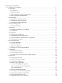
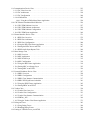


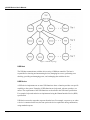


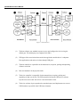


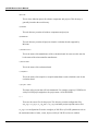


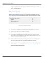
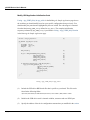

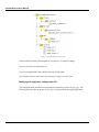


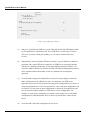


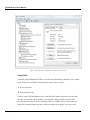
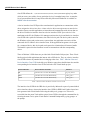


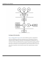
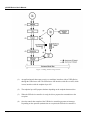


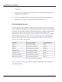


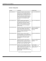

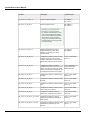
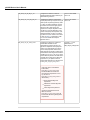
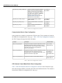

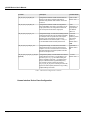
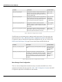
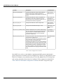

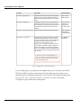
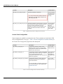


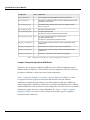
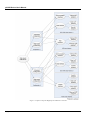
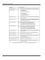


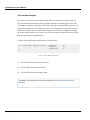


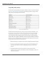


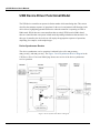


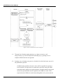
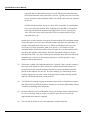

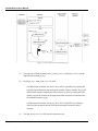
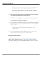
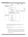


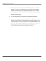


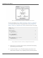


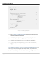


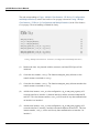

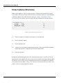

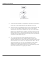
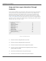
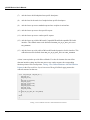
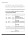
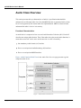
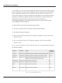


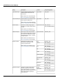


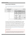


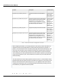
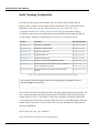

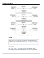

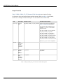


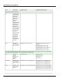


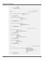


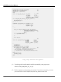


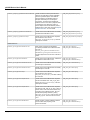
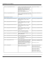
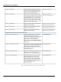

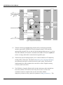


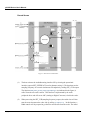


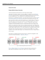
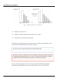
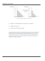

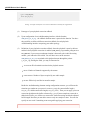


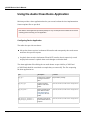

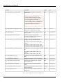
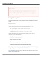
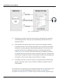
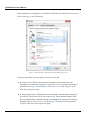
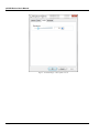
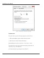
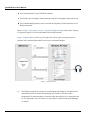
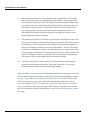

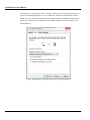


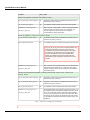


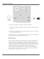


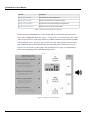


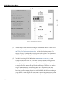


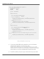

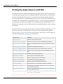

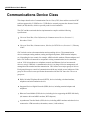


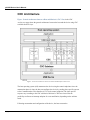

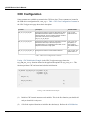

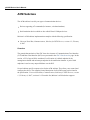
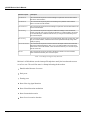
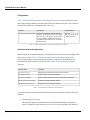

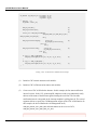
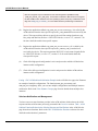


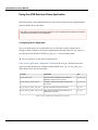


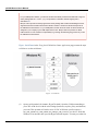


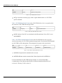


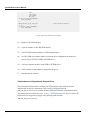
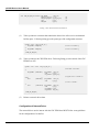

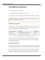


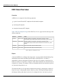


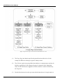


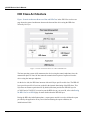

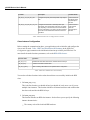

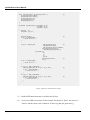

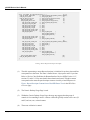
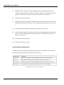
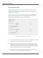


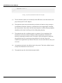

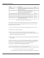
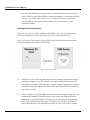
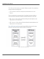


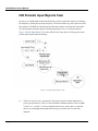


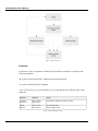
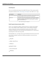

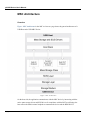


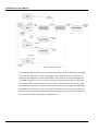
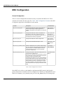
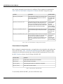


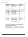
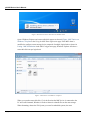


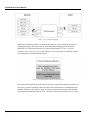


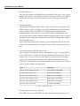
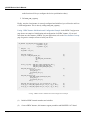

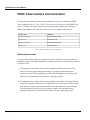


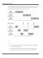
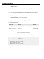


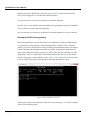


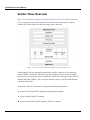

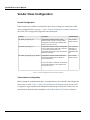

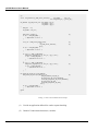


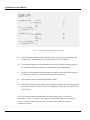

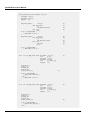


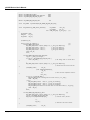


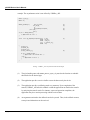


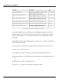


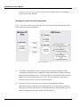


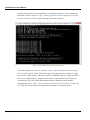


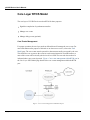
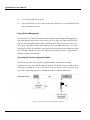

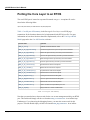

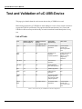


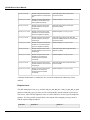


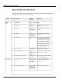
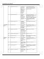
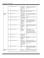
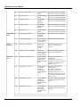

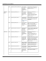
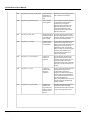


![Les blocs d`informations de la page d`accueil [v3]](http://vs1.manualzilla.com/store/data/006375479_1-e4094da53d9560c3a0eecb76542e7f0c-150x150.png)