1
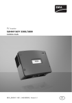
PV Inverters
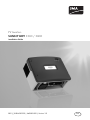
SUNNY BOY 3300 / 3800
Installation Guide
SB33_38-IEN083330 | IME-SB3800 | Version 3.0
EN
SMA Solar Technology AG
Table of Contents
Table of Contents
1
1.1
1.2
1.3
1.4
1.5
Notes on this Manual. . . . . . . . . . . . . . . . . . . . . . . . . . . . . .
Validity . . . . . . . . . . . . . . . . . . . . . . . . . . . . . . . . . . . . . . . . . . . .
Target Group . . . . . . . . . . . . . . . . . . . . . . . . . . . . . . . . . . . . . . .
Storage of the Manual . . . . . . . . . . . . . . . . . . . . . . . . . . . . . . . .
Additional Information . . . . . . . . . . . . . . . . . . . . . . . . . . . . . . . .
Symbols Used . . . . . . . . . . . . . . . . . . . . . . . . . . . . . . . . . . . . . . .
5
5
5
5
5
6
2
2.1
2.2
Safety . . . . . . . . . . . . . . . . . . . . . . . . . . . . . . . . . . . . . . . . . . 7
Appropriate Usage . . . . . . . . . . . . . . . . . . . . . . . . . . . . . . . . . . . 7
Safety Precautions. . . . . . . . . . . . . . . . . . . . . . . . . . . . . . . . . . . . 8
3
3.1
3.2
3.3
Unpacking. . . . . . . . . . . . . . . . . . . . . . . . . . . . . . . . . . . . . . . 9
Packing List . . . . . . . . . . . . . . . . . . . . . . . . . . . . . . . . . . . . . . . . . 9
Check for Transport Damage . . . . . . . . . . . . . . . . . . . . . . . . . . 10
Identification of the Sunny Boy . . . . . . . . . . . . . . . . . . . . . . . . . 10
4
4.1
Installation . . . . . . . . . . . . . . . . . . . . . . . . . . . . . . . . . . . . . 11
Selection of the Mounting Location . . . . . . . . . . . . . . . . . . . . . 11
4.1.1
Dimensions and Weight . . . . . . . . . . . . . . . . . . . . . . . . . . . . . . . . . . . . . . . . 12
4.1.2
Ambient Conditions. . . . . . . . . . . . . . . . . . . . . . . . . . . . . . . . . . . . . . . . . . . . 12
4.1.3
Minimum Clearances . . . . . . . . . . . . . . . . . . . . . . . . . . . . . . . . . . . . . . . . . . 13
4.1.4
Position . . . . . . . . . . . . . . . . . . . . . . . . . . . . . . . . . . . . . . . . . . . . . . . . . . . . . 13
4.2
Mounting instructions . . . . . . . . . . . . . . . . . . . . . . . . . . . . . . . . 14
5
5.1
5.2
5.3
Electrical Connection . . . . . . . . . . . . . . . . . . . . . . . . . . . . . 16
Overview of the Connection Area . . . . . . . . . . . . . . . . . . . . . . 16
Connection to the Public Grid (AC) . . . . . . . . . . . . . . . . . . . . . 17
Solar generator connection (DC) . . . . . . . . . . . . . . . . . . . . . . . 21
Installation Guide
SB33_38-IEN083330
3
Table of Contents
SMA Solar Technology AG
5.4
Communication. . . . . . . . . . . . . . . . . . . . . . . . . . . . . . . . . . . . . 23
5.4.1
Line-conducted Communication . . . . . . . . . . . . . . . . . . . . . . . . . . . . . . . . . . 23
5.4.2
Wireless Communication . . . . . . . . . . . . . . . . . . . . . . . . . . . . . . . . . . . . . . . 25
6
6.1
Commissioning . . . . . . . . . . . . . . . . . . . . . . . . . . . . . . . . . . 26
Display Language and LED Display . . . . . . . . . . . . . . . . . . . . . 27
6.1.1
Setting the Display Language . . . . . . . . . . . . . . . . . . . . . . . . . . . . . . . . . . . . 27
6.1.2
LED Display . . . . . . . . . . . . . . . . . . . . . . . . . . . . . . . . . . . . . . . . . . . . . . . . . . 27
7
7.1
7.2
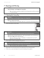
Opening and Closing. . . . . . . . . . . . . . . . . . . . . . . . . . . . . 28
Opening the Sunny Boy . . . . . . . . . . . . . . . . . . . . . . . . . . . . . . 28
Closing the Sunny Boy . . . . . . . . . . . . . . . . . . . . . . . . . . . . . . . 29
8
8.1
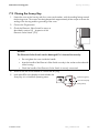
Maintenance and Cleaning . . . . . . . . . . . . . . . . . . . . . . . . 30
Checking Heat Dissipation . . . . . . . . . . . . . . . . . . . . . . . . . . . . 30
8.1.1
Cleaning the Fan. . . . . . . . . . . . . . . . . . . . . . . . . . . . . . . . . . . . . . . . . . . . . . 30
8.1.2
Cleaning the Fan Gills. . . . . . . . . . . . . . . . . . . . . . . . . . . . . . . . . . . . . . . . . . 31
8.1.3
Testing the Fan . . . . . . . . . . . . . . . . . . . . . . . . . . . . . . . . . . . . . . . . . . . . . . . 31
8.2
Inspection of the Electronic Solar Switch . . . . . . . . . . . . . . . . . 33
9
9.1
9.2
Troubleshooting . . . . . . . . . . . . . . . . . . . . . . . . . . . . . . . . . 34
Checking the Varistors . . . . . . . . . . . . . . . . . . . . . . . . . . . . . . . 34
Ground fault monitoring . . . . . . . . . . . . . . . . . . . . . . . . . . . . . . 35
10
10.1
10.2
10.3
10.4
Decommissioning . . . . . . . . . . . . . . . . . . . . . . . . . . . . . . . . 36
Disassembly . . . . . . . . . . . . . . . . . . . . . . . . . . . . . . . . . . . . . . . 36
Packaging . . . . . . . . . . . . . . . . . . . . . . . . . . . . . . . . . . . . . . . . . 37
Storage . . . . . . . . . . . . . . . . . . . . . . . . . . . . . . . . . . . . . . . . . . . 37
Disposal . . . . . . . . . . . . . . . . . . . . . . . . . . . . . . . . . . . . . . . . . . 37
11
Technical Data . . . . . . . . . . . . . . . . . . . . . . . . . . . . . . . . . . 38
12
Contact . . . . . . . . . . . . . . . . . . . . . . . . . . . . . . . . . . . . . . . . 41
4
SB33_38-IEN083330
Installation Guide
SMA Solar Technology AG
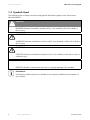
Notes on this Manual
1 Notes on this Manual
1.1 Validity
The manual describes how to install and commission SMA inverters of the types Sunny Boy 3300 and
Sunny Boy 3800.
This manual applies for the Sunny Boy 3300 firmware versions GRX33_2.85/2.79 and above and
for the Sunny Boy 3800 firmware version GRX38_2.85/2.79 and above. The firmware version is
shown in the display after starting the device.
1.2 Target Group
Only qualified electricians may install and commission Sunny Boy units.
1.3 Storage of the Manual
All manuals for the device and for the installed components must be stored in the immediate vicinity
of the device, and must be accessible at all times.
1.4 Additional Information
You will find further information on special topics such as designing a line circuit breaker or the
description of operating parameters in the download area at www.SMA.de/en.
Installation Guide
SB33_38-IEN083330
5
Notes on this Manual
SMA Solar Technology AG
1.5 Symbols Used
The following types of safety instructions and general information appear in this document as
described below:
DANGER!
DANGER indicates a hazardous situation which, if not avoided, will result in death or
serious injury.
WARNING!
WARNING indicates a hazardous situation which, if not avoided, could result in death or
serious injury.
CAUTION!
CAUTION indicates a hazardous situation which, if not avoided, could result in minor or
moderate injury.
NOTICE!
NOTICE indicates a situation that can result in property damage if not avoided.
Information
Information provides tips that are valuable for the optimal installation and operation of
your product.
6
SB33_38-IEN083330
Installation Guide
SMA Solar Technology AG
Safety
2 Safety
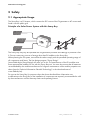
2.1 Appropriate Usage
The Sunny Boy is a PV inverter, which converts the DC current of the PV generator to AC current and
feeds it into the public grid.
Principle of a Solar Power System with this Sunny Boy
The Sunny Boy may only be operated with PV generators (modules and cabling) of protection class
II. Do not connect any sources of energy other than PV modules to the Sunny Boy.
When planning the PV system, ensure that the values comply with the permitted operating range of
all components at all times. The free design program "Sunny Design"
(www.SMA.de/en/SunnyDesign) will assist you in this. The manufacturer of the PV modules must
have approved the modules for use with this Sunny Boy unit. You must also ensure that all measures
recommended by the module manufacturer for long-term maintenance of the module properties are
taken (see also Technical Information "Module Technology", in the download area of
www.SMA.de/en).
Do not use the Sunny Boy for purposes other than those described here. Alternative uses,
modifications to the Sunny Boy or the installation of components not expressly recommended or sold
by the manufacturer void the warranty claims and operating license.
Installation Guide
SB33_38-IEN083330
7
Safety
SMA Solar Technology AG
2.2 Safety Precautions
DANGER!
Lethal danger caused by high voltages in the Sunny Boy!
• All work on the Sunny Boy must be carried out by a qualified personnel.
CAUTION!
Danger of burn injuries due to hot housing parts!
• Do not touch the housing of the Sunny Boy during operation.
Grounding the PV generator
Comply with the local requirements for grounding the modules and the PV generator. SMA
Solar Technology recommends connecting and grounding the generator frame and other
electricity conducting surfaces in such a way that there is continuous conduction in order to
achieve maximum protection for systems and persons.
8
SB33_38-IEN083330
Installation Guide
SMA Solar Technology AG
Unpacking
3 Unpacking
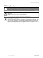
3.1 Packing List
D
B
A
E
C
L
I
F
Object
A
B
C
D
E
F
G
H
I
K
L
Installation Guide
Quantity
1
1
2
1
1
1
1
2
5
2
2
G
H
K
Description
Sunny Boy
Rear panel
Handle cover
Socket element
Set of documents with explanations and certificates
Electronic Solar Switch
Jumper for communication / fan test
Cylinder head screw and M6 contact disk
Sealing plugs for rear panel (sealing)
Cap for PV plug and PV socket
User manual (Sunny Boy and Electronic Solar Switch)
SB33_38-IEN083330
9
Unpacking
SMA Solar Technology AG
3.2 Check for Transport Damage
Check the Sunny Boy for visible external damage, such as cracks in the housing or display. Please
contact your dealer if you find any damage.
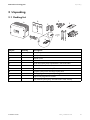
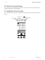
3.3 Identification of the Sunny Boy
You can identify the Sunny Boy by the type label. The type label is found on the right-hand side of the
housing.
SMA Solar Technology AG
www.SMA.de
Device type
SUNNY BOY
Photovoltaic string inverter
Serial number
Made in Germany
Type
Serial No.
SB 3800
2000165882
V DC max
500 V
V DC MPP
200-400 V
I DC max
20 A
V AC nom
230 V
f AC nom
50/60 Hz
PAC nom
3800 W
I AC nom
16.5 A
cos j
1
VDE 0126-1-1 (2.06)
outdoor
GÜTEZEICHEN
Solar
*2000165882*
10
SB33_38-IEN083330
Installation Guide
SMA Solar Technology AG
Installation
4 Installation
4.1 Selection of the Mounting Location
DANGER!
Danger to life due to fire or explosion!
Despite careful construction, a fire can occur with electrical devices.
Do not install the Sunny Boy
• on flammable construction materials,
• in areas where highly flammable materials are stored,
• in potentially explosive areas!
CAUTION!
Danger of burn injuries due to hot housing parts!
• Mount the Sunny Boy in such a way that it cannot be touched inadvertently during
operation.
Installation Guide
SB33_38-IEN083330
11
Installation
SMA Solar Technology AG
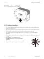
352 mm
4.1.1 Dimensions and Weight
450
mm
m
6m
23
41 kg
4.1.2 Ambient Conditions
• The mounting location and mounting method must be suitable for the weight and dimensions.
• Mount on a solid surface.
• The mounting location must be accessible at all times (do not mount in inaccessible locations).
• TheSunny Boy must be easy to remove from the mounting location at any time.
• The ambient temperature should be between -25 °C and +60 °C to guarantee optimal
operation.
• Do not expose the Sunny Boy to direct sunlight, so as to avoid power reduction due to excessive
heating.
• In living areas, do not install the unit on
plasterboard walls, etc. so as to avoid audible
vibrations.
The Sunny Boy can make noises when in use which
may be perceived as a nuisance in a living area.
12
SB33_38-IEN083330
Installation Guide
SMA Solar Technology AG
Installation
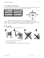
4.1.3 Minimum Clearances
Observe the following minimum clearances to walls, other devices or objects to guarantee sufficient
heat dissipation and enough space for removing the Electronic Solar Switch.
Direction
Sides
Above
Bottom
Front
Minimum clearance
30 cm
20 cm
50 cm
5 cm
Multiple Sunny Boys installed in areas with high ambient temperatures
If necessary, increase the clearances between the individual Sunny Boys, and ensure that
there is enough ventilation to ensure sufficient cooling of the Sunny Boys.
4.1.4 Position
• Vertical installation or tilted backwards by max. 45°.
• Never install the device with a forward tilt.
• Do not install horizontally.
• Install at eye level to allow operating modes to be read at all times.
Installation Guide
SB33_38-IEN083330
13
Installation
SMA Solar Technology AG
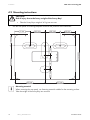
4.2 Mounting instructions
CAUTION!
Risk of injury due to the heavy weight of the Sunny Boy!
• Take the Sunny Boys weight of 41 kg into account.
1. Use the rear panel as a drilling template and mark the positions of the drill holes.
125 mm
125 mm
92 mm
345,8 mm
88,4 mm
103,8 mm
267,2 mm
75 mm
78,6 mm
92 mm
217 mm
217 mm
Mounting material
When mounting the rear panel, use fastening material suitable for the mounting surface.
Take the weight of the Sunny Boy into account!
14
SB33_38-IEN083330
Installation Guide
SMA Solar Technology AG
Installation
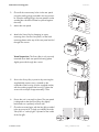
2. Close all the unnecessary holes in the rear panel
using the sealing plugs provided in the accessories
kit. Insert the sealing plugs in the rear panel from the
outside (the side that will later be placed against
the wall).
3. Mount the rear panel.
4. Attach the Sunny Boy by hanging its upper
mounting slots onto the rear panel, so that both
mounting plates at the top of the rear panel are fed
through the cutouts.
SMA
SOLAR
TECHNOLO
GY
SUNN
Y BOY
Visual inspection: The Sunny Boy is only correctly
mounted when both rear panel mounting plates
slightly protrude through the cutouts.
SMA
SOLAR
TECHNO
LOGY
SUNN
Y BOY
5. Secure the Sunny Boy in position by screwing the
supplied M6 contact screw, situated on the
underside of the housing. Use the supplied washer,
with the toothing against the housing. Tighten the
screw with a torque of approximately 5 Nm.
6. Ensure the unit is correctly in place. The rear panel
is designed so that the Sunny Boy tilts slightly
backwards on a perfectly vertical wall.
7. Close the recessed grips with the fan gills provided
in the accessories kit. To help you identify the sides,
"links/left" or "rechts/right" is printed on the inside
of the fan gills.
Installation Guide
SB33_38-IEN083330
15
Electrical Connection
SMA Solar Technology AG
5 Electrical Connection
NOTICE!
Static discharges can damage the Sunny Boy!
• Before you touch a component inside the Sunny Boy ground yourself by touching PE
or a grounded object.
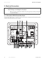
5.1 Overview of the Connection Area
The following diagram gives a schematic overview of the various components and connection points
inside the Sunny Boy with the cover removed:
A
E F G F H
16
SB33_38-IEN083330
C
B
I
D
K L
I
M
Installation Guide
SMA Solar Technology AG
Object
A
B
C
D
E
F
G
H
I
K
L
M
Electrical Connection
Description
Communication socket
Flat connection for grounding the cable shield with line-conducted communication
Sunny Display
Jumper slot for fan test
Varistors
Housing opening with sealing plugs for communication
Communication terminal
Jumper slot for communication
PV input plug
Electronic Solar Switch (ESS)
Operating status LEDs
AC plug for grid connection
5.2 Connection to the Public Grid (AC)
Low voltage grid 220 V – 240 V
Comply with the connection regulations of your local grid operator.
The Sunny Boy must have a three-wire connection to the grid (L, N, PE).
The grid connection terminals on the AC connection socket included in the accessories kit can take
wires with a cross-section of up to 4 mm².
The AC connection socket accessories kit contains two sealing rings for the different cable diameters.
The threaded sleeve comes from the factory already equipped with a sealing ring for cable diameters
from 10 to 14 mm. If you want to install cable with a diameter of between 6 and 10 mm, you have
to exchange the sealing ring with the one included in the accessories kit.
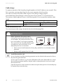
Cable requirements
External diameter
6 – 14 mm
Installation Guide
SB33_38-IEN083330
17
Electrical Connection
SMA Solar Technology AG
Cable design
For optimum operation of the Sunny Boy the grid impedance of the AC cable must not exceed 1 Ohm.
This is necessary, amongst other things, for the correct operation of the Sunny Boy.
The cable cross-section should be sized using the "Sunny Design" design program
(www.SMA.de/en/SunnyDesign) so that output losses do not exceed 1 % at nominal power.
The maximum cable lengths are shown in the following table. Do not exceed the maximum cable
length.
Cable cross-section
Sunny Boy 3300
18.5 m
4 mm2
Max. cable length
Sunny Boy 3800
16 m
Load disconnection unit
The maximal permissible rating is located in the technical data (page 38).
DANGER!
Risk of lethal burns!
When a generator (Sunny Boy) and a
consumer are connected to the same line
circuit breaker, the protective function of the
line circuit breaker is no longer guaranteed.
The current from the Sunny Boy and the grid
can add up to overcurrent which is not
detected by the line circuit breaker.
• Never connect loads between the Sunny Boy and the line circuit breaker without
protection.
• Always install separate fuses for loads.
Load disconnection unit
A circuit breakers load disconnecting properties can be utilized to disconnect the Sunny
Boy from the grid underload.
A screw type fuse element, e.g. D system (Diazed) or D0 system (Neozed) has no load
disconnecting properties and thus may be used as cable protection, but not as a load
disconnection unit.
Upon disconnection under load, the fuse element may be destroyed or its functionality may
be impaired by contact burning.
18
SB33_38-IEN083330
Installation Guide
SMA Solar Technology AG
Electrical Connection
Connection procedure
1. Check the grid voltage and compare it with "Vac" on the type label.
The exact operating range of the Sunny Boy is specified in the operating parameters. You will
find the relevant document in the download area at www.SMA.de/en.
2. Switch off the line circuit breaker and secure it to prevent it from being reactivated.
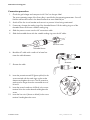
3. If necessary change the sealing ring of the threaded sleeve. Pull the sealing ring out of the
threaded sleeve and insert a smaller sealing ring.
4. Slide the pressure screw over the AC connection cable.
5. Slide the threaded sleeve with the suitable sealing ring over the AC cable.
Pressure screw
Threaded sleeve
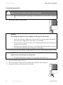
6. Bend the AC cable with a radius of at least four
times the cable diameter.
min. 4 x cable
diameter
7. Shorten the cable.
8. Insert the protective earth PE (green-yellow) in the
screw terminal with the earth sign on the socket
element and tighten the screw. The PE protective
earth must be longer than the connected wires of
N and L.
9. Insert the neutral conductor N (blue) in the screw
terminal N on the socket element and tighten the
screw.
10. Insert the live wire L (brown or black) in the screw
terminal L and tighten the screw.
Installation Guide
SB33_38-IEN083330
19
Electrical Connection
SMA Solar Technology AG
DANGER!
Danger to life due to non-earthed housing!
When laying the AC cable, the PE conductor and the other conductors can be extracted
from the socket element after they have been connected.
• Make sure the wires are securely
connected.
Connected wires
• Do not bend the AC cable once it has
been connected.
• Do not subject the socket element to
heavy loads.
Socket element
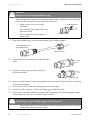
11. Press the threaded sleeve into the socket element until it audibly engages.
Socket element with
threaded sleeve
Pressure screw
12. Screw the pressure screw tightly onto the threaded
sleeve.
13. Tighten the safety ring to provide sealing and
provide strain relief.
Safety ring
14. Close the socket element with the cap supplied in the accessories kit if the Sunny Boy is not being
connected immediately.
15. Remove the protective cap of the flange plug on the Sunny Boy.
16. Connect the AC connection socket to the flange plug on the Sunny Boy.
17. Press the AC connection socket firmly against the flange plug until it audibly engages. Make
sure the alignment of the AC connection socket is correct.
DANGER!
Lethal danger caused by high voltages in the Sunny Boy!
• Do not switch on the line circuit breaker until the solar generator has been connected
and the Sunny Boy is securely closed.
20
SB33_38-IEN083330
Installation Guide
SMA Solar Technology AG
Electrical Connection
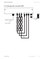
5.3 Solar generator connection (DC)
4.0 mm2
Communication
String 1
String 2
String 3
Installation Guide
SB33_38-IEN083330
21
Electrical Connection
SMA Solar Technology AG
Connection procedure
DANGER!
Danger to life due to high voltages on the Sunny Boy
• Before connecting the PV generator, ensure that the line circuit breaker is switched
off.
1. Remove the Electronic Solar Switch.
NOTICE!
Exceeding the maximum input voltage can destroy the Sunny Boy!
• Check the connection cables of the solar modules for correct polarity and that the
maximum input voltage of the Sunny Boy is not exceeded.
• Do not connect strings with an open circuit voltage greater than the maximum input
voltage of the Sunny Boy.
• Check the system design if the open circuit voltage of the solar modules is less than
10 % below the maximum input voltage of the Sunny Boy.
2. Check the strings for ground faults, as described in section 9.2 „Ground fault monitoring“ (35).
NOTICE!
High currents can damage the Sunny Boy!
• The maximum possible current per DC plug may not exceed 16 A.
3. Connect the DC plug connectors.
4. Close unused input sockets with the sealing caps included in the packing list.
5. Reinsert the Electronic Solar Switch in the socket.
22
SB33_38-IEN083330
Installation Guide
SMA Solar Technology AG
Electrical Connection
NOTICE!
The Electronic Solar Switch can be damaged if it is inserted incorrectly!
• Do not tighten the screw inside the handle.
• Insert the handle of the Electronic Solar Switch securely in the socket on the underside
of the housing.
• Check the handle of the Electronic Solar Switch is securely connected.
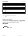
5.4 Communication
There are various types of communication interfaces. These communication interfaces are used to
communicate with SMA communication devices or a PC with appropriate software.
See the communication device documentation for a detailed wiring diagram.
5.4.1 Line-conducted Communication
Connection procedure for line-conducted communication
NOTICE!
Electrostatic discharges can damage the communication interface!
• Before unpacking the communication interface ground yourself by touching PE or a
grounded object.
1. Open the Sunny Boy as described in section 7.1 „Opening the Sunny Boy“ (28).
2. Remove the sealing plugs from the housing feed-through.
3. Guide the PG screw fitting over the communication cable.
4. Guide the communication cable through the cable feed-through (A) of the Sunny Boy.
5. Screw the PG screw fitting onto the Sunny Boy.
6. Tighten the sealing ring of the PG screw fitting to ensure sealing and strain relief.
7. Sheathe the communication cable inside the Sunny Boy using the silicone tube included in the
packing list.
8. Lay the cable in area (B). See the figure to the right.
9. Ground the communication cable at the PE connector (C) if the connection plan of the
communication device indicates this as necessary.
NOTICE!
Connecting the receiver incorrectly can damage the devices!
• Connect the communication cables to the screw terminal strip (D) as described in the
connection plan of the communication device.
Installation Guide
SB33_38-IEN083330
23
Electrical Connection
SMA Solar Technology AG
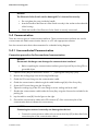
10. Note down the conductor color coding for the respective pin numbers.
– Pin 2 color:______________________
– Pin 3 color:______________________
– Pin 5 color:______________________
– Pin 7 color:______________________
11. Connect the jumpers (E) if the connection plan of the communication device indicates this as
necessary. Details on the jumper functions can be found in the communication device
documentation.
12. Plug the communication interface to the left of the board (F).
13. Close the Sunny Boy as described in section 7.2 „Closing the Sunny Boy“ (29).
F
E
D
C
A
B
Object
A
B
C
D
E
F
Description
Housing feed-through with sealing plugs in the base of the Sunny Boy
Cable route (gray surface)
PE connector
Screw terminals for connection of the communication wires
Jumper slot
Interface port
24
SB33_38-IEN083330
Installation Guide
SMA Solar Technology AG
Electrical Connection
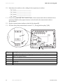
5.4.2 Wireless Communication
Connection procedure for wireless communication
1. Open the Sunny Boy as described in section 7.1 „Opening the Sunny Boy“ (28).
2. Remove the sealing plugs from the housing feed-through.
3. Guide the antenna cable through the cable feed-through (A) of the Sunny Boy.
4. Screw the PG screw fitting onto the Sunny Boy.
5. Lay the cable in area (B). See the figure below.
6. Plug the communication interface to the left of the board (C).
7. Screw the antenna cable with the antenna connection to the interface as described in the
communication documentation.
8. Close the Sunny Boy as described in section 7.2 „Closing the Sunny Boy“ (29).
C
A
Object
A
B
C
B
Description
Housing feed-through with sealing plugs in the base of the Sunny Boy
Cable route (gray surface)
Interface port
Installation Guide
SB33_38-IEN083330
25
Commissioning
SMA Solar Technology AG
6 Commissioning
Check the following requirements before commissioning:
• correct connection of the AC (grid) cable
• full connection of the DC cables (PV strings)
• unused DC plug connectors on the underside of the housing are sealed with caps
• the housing lid is securely screwed in place
• the Electronic Solar Switch is securely plugged
• the line circuit breaker is laid out correctly
Commissioning procedure
1. Switch on the line circuit breaker.
2. An illuminated or blinking green LED signals faultfree operation. If this is the case, commissioning
was completed successfully.
Operation (green)
Ground fault (red)
Fault (yellow)
NOTICE!
Excessive DC input voltage can destroy the Sunny Boy!
• Disconnected the grid voltage and the
PV generator if after a short time the
bottom yellow LED flashes four times at
intervals of one second and the display
shows the message on the right.
26
SB33_38-IEN083330
Installation Guide
SMA Solar Technology AG
Commissioning
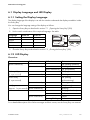
6.1 Display Language and LED Display
6.1.1 Setting the Display Language
The display language of the display is set with the switches underneath the display assemblies inside
the Sunny Boy.
You can change the language setting of the display as follows:
1. Open the Sunny Boy as described in section 7.1 „Opening the Sunny Boy“ (28).
2. Set the switch combination of the required language. See table.
Language
German
English
French
Spanish
Switch S2
B
B
A
A
Switch S1
B
A
B
A
3. Close the Sunny Boy as described in section 7.2 „Closing the Sunny Boy“ (29).
6.1.2 LED Display
Overview
Green
glows continuously
Red
—
glows continuously
blinks quickly
(3 x per second)
blinks slowly
—
glows continuously
Yellow
—
—
glows continuously
—
—
Status
OK (feeding operation)
Warning
OK (initialization)
OK (stop)
Warning
—
—
OK (waiting,
—
—
—
grid monitoring)
Warning
OK (derating)
Warning
—
—
—
glowing/blinking
OK (night shutdown)
Failure
Failure
Failure
(1 x per second)
glows continuously
briefly goes out
—
(approx. 1 x per second) glows continuously
—
—
glows continuously
For a detailed description of the failure messages and their causes, see the Sunny Boy user manual.
Installation Guide
SB33_38-IEN083330
27
Opening and Closing
SMA Solar Technology AG
7 Opening and Closing
NOTICE!
Static discharges can damage the Sunny Boy!
• Before you touch a component inside the Sunny Boy ground yourself by touching PE
or a grounded object.
7.1 Opening the Sunny Boy
DANGER!
Lethal danger caused by high voltages in the Sunny Boy!
Before you open the Sunny Boy:
• Switch off the line circuit breaker and secure it to prevent it from being reactivated.
1. Remove the Electronic Solar Switch.
DANGER!
Danger to life due to unsafe disconnection from the PV-Generator!
Safe disconnection from the PV generator is only guaranteed after removal of the Electronic
Solar Switch, and of all DC plug connectors.
• Remove the DC plug connector immediately to completely disconnect the PV
generator from the Sunny Boy.
2. Check whether the LEDs and display have gone out.
DANGER!
Lethal danger caused by high voltages in the Sunny Boy!
• Wait 15 minutes for the capacitors to discharge.
3. Remove the screws from the housing cover and pull the cover forward smoothly.
4. Put the cover, screws and washers to one side so that they do not get lost.
28
SB33_38-IEN083330
Installation Guide
SMA Solar Technology AG
Opening and Closing
7.2 Closing the Sunny Boy
1. Fasten the cover to the housing with four screws and washers, with the toothing facing toward
the housing cover. The screws must be tightened with approximately 6 Nm torque to ensure the
sealing of the housing and the grounding of the cover.
2. Connect the PV generator.
3. Check the Electronic Solar Switch for wear, as
described in section 8.2 „Inspection of the
Electronic Solar Switch“ (33).
NOTICE!
The Electronic Solar Switch can be damaged if it is inserted incorrectly!
• Do not tighten the screw inside the handle.
• Insert the handle of the Electronic Solar Switch securely in the socket on the underside
of the housing.
• Check the handle of the Electronic Solar Switch is securely connected.
4. Switch on the line circuit breaker or connect the AC plug.
5. Look at the LEDs or the display to check whether the
Sunny Boy is in a fault-free operating status.
Operation (green)
Ground fault (red)
Fault (yellow)
Installation Guide
SB33_38-IEN083330
29
Maintenance and Cleaning
SMA Solar Technology AG
8 Maintenance and Cleaning
8.1 Checking Heat Dissipation
You only need to check the heat dissipation of the Sunny Boy if during a visual inspection you notice
a marked build-up in the fan guard or the Sunny Boy is increasingly observed to be in derating mode.
Whether the Sunny Boy switches to derating mode depends on the ambient temperature and cooling
efficiency.
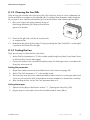
8.1.1 Cleaning the Fan
If the fan guard is only covered in loose dust it can be cleaned with a vacuum cleaner. If you do not
achieve satisfactory results with a vacuum cleaner, you can dismantle the fan for cleaning.
If the fan guard is heavily soiled, proceed as follows:
1. Disconnect the Sunny Boy from both the DC and
AC connections.
2. Wait for the fan to stop rotating.
3. Push the latches of the plastic cover to the right and
remove the plastic cover carefully along with the
fan guard fitted behind.
Plastic cover
4. Clean the fan guard with a soft brush, a paint brush,
a cloth or compressed air.
The fan behind the guard is attached to the housing of the Sunny Boy with three plastic clips. If this is
also soiled clean it as follows:
5. Push the two upper plastic clips backward and the lower plastic clip forward.
6. Remove the fan by pulling is slowly and carefully downwards.
7. Unlock and unplug the fan plug inside the Sunny Boy.
8. Clean the fan with a soft brush, a paint brush, or a cloth. Under no circumstances should you
use compressed air to clean the fan. This can damaged the fan.
9. After cleaning, assemble everything in reverse order.
10. Check that the fan is functional.
30
SB33_38-IEN083330
Installation Guide
SMA Solar Technology AG
Maintenance and Cleaning
8.1.2 Cleaning the Fan Gills
There are fan gills on either side of the Sunny Boy. The Sunny Boy sucks air in from underneath via
the fan and blows it out again on the left-hand side. For optimum heat dissipation within the device,
all you have to do is clean the left-hand fan gill. Proceed as follows when cleaning the fan gill(s):
11. Place your finger in the space between the top of
the housing and the fan gill. Gently pull the left fan
gill out of its bracket.
12. Clean the fan gills with a soft brush, a paint brush,
or compressed air.
13. Reattach the fan gills to the Sunny Boy. To help you identify the sides, "links/left" or "rechts/right"
is printed on the inside of the fan gills.
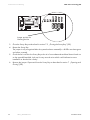
8.1.3 Testing the Fan
There are two ways to check the fan is functional:
• Set the "Fan Test" parameter to "1" in the installer mode (using Sunny Data, Sunny Data Control
or the Sunny Boy Control data logger).
• Connect the jumper to the controller board (the jumper for checking the fans is included in the
Sunny Boy accessories kit).
Setting the parameter
1. Request the installer password on the SMA Service Line (contact: see page 59).
2. Set the "Fan Test" parameter to "1" in the installer mode.
3. The Sunny Boy sucks air in from underneath and then blows it back out on the upper sides. Look
out for any unusual noise which could indicate incorrect installation or that the fans are faulty.
4. After checking the fans, set the "Fan Test" parameter back to 0.
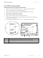
Setting the jumper
1. Open the Sunny Boy as described in section 7.1 „Opening the Sunny Boy“ (28).
2. Plug the jumper in the jumper slot on the controller board as shown below.
Installation Guide
SB33_38-IEN083330
31
Maintenance and Cleaning
SMA Solar Technology AG
Jumper position for
checking the fan
3. Close the Sunny Boy as described in section 7.2 „Closing the Sunny Boy“ (29).
4. Restart the Sunny Boy.
The jumper is only recognized after the system has been restarted (i.e. all LEDs must have gone
out before a restart).
5. Check the fan‘s air-flow: the Sunny Boy sucks air in from underneath and then blows it back out
on the upperleft-handside. Look out for any unusual noise which could indicate incorrect
installation or that the fan is faulty.'
6. Remove the jumper. Open and close the Sunny Boy as described in section 7 „Opening and
Closing“ (28).
32
SB33_38-IEN083330
Installation Guide
SMA Solar Technology AG
Maintenance and Cleaning
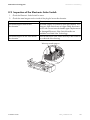
8.2 Inspection of the Electronic Solar Switch
1. Check the Electronic Solar Switch for wear.
2. Check the metal tongues on the inside of the plug for brown discoloration.
Event
The metal tongues show brown
discoloration.
The metal tongues do not show brown
discoloration.
Measure
The metal tongues is burned out (see figure below). The
Electronic Solar Switch can no longer safely disconnect
the DC side. Do not insert the handle again. Replacements
for damaged Electronic Solar Switch handles are
available from SMA Solar Technology.
Insert the Electronic Solar Switch securely in the socket on
the underside of the housing.
Worn-out metal tongues
Installation Guide
SB33_38-IEN083330
33
Troubleshooting
SMA Solar Technology AG
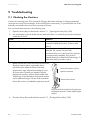
9 Troubleshooting
9.1 Checking the Varistors
Varistors are wearing parts. Their functional efficiency diminishes with age or following repeated
responses as a result of overvoltages. If the red LED glows continuously, it is possible that one of the
thermally monitored varistors has lost its protective function.
You can check these varistors in the following way:
1. Open the Sunny Boy as described in section 7.1 „Opening the Sunny Boy“ (28).
2. Use a multimeter to check all the varistors and see if there is a conducting connection between
connectors 2 and 3.
Event
There is a conducting connection.
There is no conducting connection.
Measure
There is probably another fault in the Sunny Boy.
Contact the SMA Service Line. Continue with
point 4.
The respective varistor is defective and must be
replaced. The varistors are specially
manufactured for use in the Sunny Boy and are
not commercially available. They must be
ordered directly from SMA Solar Technology. To
replace the part, proceed to step 3.
3. Replace all varistors with new ones as shown in this
drawing. Varistor failure is generally due to
influences which affect all varistors similarly
(temperature, age, induced overvoltages). If you
do not receive a special tool together with the
replacement varistors, please contact SMA Solar
Technology. As an alternative, the terminal contacts
can be operated using a 3.5 mm wide screwdriver.
Ensure the varistor is installed the right way round!
Insert the extractor tool to
open the terminal
Remove the varistor
The pole with the small loop (crimp) must
be fitted to terminal 1 when replacing the
varistor
4. Close the Sunny Boy as described in section 7.2 „Closing the Sunny Boy“ (29).
34
SB33_38-IEN083330
Installation Guide
SMA Solar Technology AG
Troubleshooting
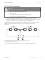
9.2 Ground fault monitoring
DANGER!
Danger to life due to live PV generator!
• Do not touch the frame of the solar generator.
• Do not touch PE.
• Do not connect strings with ground faults to the Sunny Boy.
• Wait until there is no voltage measurement.
1. Open the Sunny Boy as described in section 7.1 „Opening the Sunny Boy“ (28).
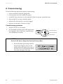
2. Measure the voltages between the plus and minus pole of a string against the ground potential.
If a voltage is present, there is a ground fault in the corresponding string.
The approximate position of the ground fault can be determined from the ratio of the measured
voltages between plus against ground potential and minus against ground potential.
For example:
The ground fault is between the second and third module in this case.
3. Repeat point 2 for each string.
4. Close the Sunny Boy as described in section 7.2 „Closing the Sunny Boy“ (29).
Installation Guide
SB33_38-IEN083330
35
Decommissioning
SMA Solar Technology AG
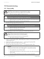
10 Decommissioning
10.1 Disassembly
CAUTION!
Risk of injury due to the heavy weight of the Sunny Boy!
• Take the Sunny Boys weight of 41 kg into account.
DANGER!
Lethal danger caused by high voltages in the Sunny Boy!
• Switch off the line circuit breaker and secure it to prevent it from being reactivated.
• Remove the AC connection socket from the Sunny Boy.
1. Close the AC flange plug with the protective cap.
DANGER!
Danger to life due to unsafe disconnection from the solar generator!
• Remove the Electronic Solar Switch handle.
• Disconnect all the DC plug connectors.
2. Close the DC input sockets with the sealing caps included in the packing list.
CAUTION!
Danger of burn injuries due to hot housing parts!
The Sunny Boy housing can become hot during operation.
• Wait until the housing has cooled down.
3. If there is a communication cable, continue with point 7. If there is no communication cable,
continue with point 10.
4. Open the Sunny Boy as described in section 7.1 „Opening the Sunny Boy“ (28).
5. Remove the communication cable from the Sunny Boy.
6. Close the Sunny Boy as described in section 7.2 „Closing the Sunny Boy“ (29).
NOTICE!
The Electronic Solar Switch can be damaged if it is inserted incorrectly!
• Do not tighten the screw inside the handle.
• Insert the handle of the Electronic Solar Switch securely in the socket on the underside
of the housing.
• Check the handle of the Electronic Solar Switch is securely connected.
36
SB33_38-IEN083330
Installation Guide
SMA Solar Technology AG
Decommissioning
7. Remove the securing screw.
8. Remove the Sunny Boy from the rear panel.
10.2 Packaging
If possible, please pack the Sunny Boy in the original packaging. If this is no longer available, you
can also use an equivalent box that fulfills the following requirements:
• suitable for loads up to 41 kg
• with handle system
• can be closed fully
10.3 Storage
Store the Sunny Boy in a dry place where the ambient temperatures are always between -25 °C
and +60 °C.
10.4 Disposal
Dispose of the Sunny Boy at the end of its service life in accordance with the disposal regulations for
electronic waste which apply at the installation site at that time. Alternatively, send it back to SMA
Solar Technology with shipping paid by sender, and labeled "ZUR ENTSORGUNG" ("for disposal").
Installation Guide
SB33_38-IEN083330
37
Technical Data
SMA Solar Technology AG
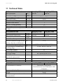
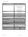
11 Technical Data
PV-Generator connection data
Max. input power
Max. input voltage
Input voltage, MPP range
Max. input current
Max. current per DC plug
Number of MPP trackers
Max. no. of strings (parallel)
Operating internal consumption
PDC
UPV 0
UPV
IPV, max
Sunny Boy 3300
3820 W
Sunny Boy 3800
4040 W
500 V a)
200 V – 400 V
20 A
16 A
1
3
<7W
a) The maximum open circuit voltage, which can occur at a cell temperature of -10 °C, may not exceed the maximum input
voltage.
Grid connection data
Nominal output power
Max. nominal output power
Max. output current
Max. allowed fuse protection
Harmonic distortion of output current
(at THD < 2 %, PAC > 0.5 PACnom)
Nominal AC voltage / range
AC grid frequency (self-adjusting)
operating range
Overvoltage category
Test voltage (50 Hz)
Test surge voltage
Power factor
(at nominal output power)
AC connection
Internal consumption at night
General data
EC Declaration of Conformity
Dimensions (W / H / D) in mm
Weight
Protection rating in accordance with
DIN EN 60529
38
SB33_38-IEN083330
PAC, nom
PAC, max
IAC, max
KIAC
UAC
fAC
cos Phi
Sunny Boy 3300
3300 W
3600 W
Sunny Boy 3800
3800 W
3800 W
18 A
25 A
<3%
220 V – 240 V / 180 V – 260 V
50 Hz / 60 Hz / ±4.5 Hz
III
1.4 kV
4 kV (serial interface: 6 kV)
1
single-phase
< 0.1 W
Sunny Boy 3300
Sunny Boy 3800
enclosed set of documents,
download area at www.SMA.de/en under
Certificate
450 / 352 / 236
41 kg
IP65
Installation Guide
SMA Solar Technology AG
Technical Data
General data
Sunny Boy 3300
Sunny Boy 3800
Climatic conditions in accordance with DIN EN 60529:
Location of type C:
Class 4K4H
extended temperature range:
-25 °C to +60 °C
extended air humidity range:
0 ... 100 %
extended air pressure range:
Transport of type E:
79.5 kPa to 106 kPa
Class 2K3
Temperature range:
Operation temperature range
Max. operating altitude
Topology
Cooling concept
Fan connections
-25 °C to +70 °C
-25 °C to +60 °C
2000 m above sea level
Low frequency transformer
OptiCool
designed for safe disconnection
according to DIN EN 50178:1998-04
Protective function DC side
All-pole disconnection unit on the DC side
Overvoltage protection
Personal protection
Reverse polarity protection
Electronic Solar Switch, DC plug connector
thermally monitored varistors
Insulation monitoring (Riso > 1 MOhm)
via short-circuit diode
Protective function AC side
Short-circuit proofing
All-pole disconnection unit on grid side
Current control
Automatic disconnection device
(SMA grid guard 2)
Efficiency
Max. efficiency ηmax
Euro ETA ηeuro
Installation Guide
Sunny Boy 3300
95,2 %
94,4 %
Sunny Boy 3800
95,6 %
94,7 %
SB33_38-IEN083330
39
Technical Data
SMA Solar Technology AG
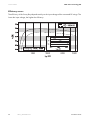
Efficiency curves
The efficiency of the Sunny Boy depends mainly on the input voltage of the connected PV strings. The
lower the input voltage, the higher the efficiency.
40
SB33_38-IEN083330
Installation Guide
SMA Solar Technology AG
Contact
12 Contact
If you have technical problems concerning our products, please contact the SMA Service Line. We
require the following information in order to provide you with the necessary assistance:
• Sunny Boy device type
• serial number of the Sunny Boy
• type and number of modules connected
• blink code or display of the Sunny Boy
• type of communication, if applicable
SMA Solar Technology AG
Sonnenallee 1
34266 Niestetal, Germany
Tel. +49 561 9522499
Fax +49 561 95224699
[email protected]
www.SMA.de
Installation Guide
SB33_38-IEN083330
41
Contact
42
SMA Solar Technology AG
SB33_38-IEN083330
Installation Guide
SMA Solar Technology AG
Legal Restrictions
The information contained in this document is the property of SMA Solar Technology AG. Publishing its content, either partially or
in full, requires the written permission of SMA Solar Technology AG. Any internal company copying of the document for the
purposes of evaluating the product or its correct implementation is allowed and does not require permission.
Exclusion of liability
The general terms and conditions of delivery of SMA Solar Technology AG shall apply.
The content of these documents is continually checked and amended, where necessary. However, discrepancies cannot be
excluded. No guarantee is made for the completeness of these documents. The latest version is available online at www.SMA.de
or from the usual sales channels.
Guarantee or liability claims for damages of any kind are excluded if they are caused by one or more of the following:
• Damages during transportation
• Improper or inappropriate use of the product
• Operating the product in an unintended environment
• Operating the product whilst ignoring relevant, statutory safety regulations in the deployment location
• Ignoring safety warnings and instructions contained in all documents relevant to the product
• Operating the product under incorrect safety or protection conditions
• Altering the product or supplied software without authority
• The product malfunctions due to operating attached or neighboring devices beyond statutory limit values
• In case of unforeseen calamity or force majeure
The use of supplied software produced by SMA Solar Technology AG is subject to the following conditions:
• SMA Solar Technology AG rejects any liability for direct or indirect damages arising from the use of software developed by
SMA Solar Technology AG. This also applies to the provision or non-provision of support activities.
• Supplied software not developed by SMA Solar Technology AG is subject to the respective licensing and liability agreements
of the manufacturer.
SMA Factory Warranty
The current guarantee conditions come enclosed with your device. These are also available online at www.SMA.de and can be
downloaded or are available on paper from the usual sales channels if required.
Trademarks
All trademarks are recognized even if these are not marked separately. Missing designations do not mean that a product or brand
is not a registered trademark.
SMA Solar Technology AG
Sonnenallee 1
34266 Niestetal
Germany
Tel. +49 561 9522-0
Fax +49 561 9522-100
www.SMA.de
E-Mail: [email protected]
© 2004 to 2008 SMA Solar Technology AG. All rights reserved
Installation Guide
SB33_38-IEN083330
43
SMA Solar Technology AG
www.SMA.de
Sonnenallee 1
34266 Niestetal, Germany
Tel.: +49 561 9522 4000
Fax: +49 561 9522 4040
E-Mail: [email protected]
Freecall: 0800 SUNNYBOY
Freecall: 0800 78669269