1
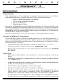
TM
OMNIGUARD 4
DIFFERENTIAL PRESSURE RECORDER
Owner's Manual
OMNIGUARD 4
Differential Pressure Recorder
Serial #:
The serial number is located inside the case lid.
Dealer Name and Address:
Name
Address
City, State, Zip
Phone
Date of Purchase:
Registered to:
Name
Address
City, State, Zip
Phone
6000 Southcenter Blvd, Suite 70
Seattle, Washington 98188-2439
(206) 241-9395 • (206) 241-9411 fax
www.engsolinc.com
S
O
L
U
T
I
O
N
S
Contents
Introduction ................................................................................. 2
Section 1: Basic Care ................................................................... 4
Section 2: Navigating The LCD Display ........................................ 5
Section 3: Quick Setup & Usage .................................................. 6
Sample Session: Viewing/Changing Settings .................. 6
Hanging the Omniguard 4 ..................................................... 7
Display Modes ...................................................................... 7
Loading the Thermal Printer Paper ....................................... 8
Section 4: Detailed Operation ...................................................... 9
Work Area Setup ................................................................... 9
Power-Up ............................................................................. 9
Contractor Name .................................................................. 10
Date & Time .......................................................................... 10
Alarm Setpoint Selection ...................................................... 11
Example of Setting Alarm Levels .................................... 11
Starting/Ending A Job ........................................................... 12
Alarm Condition .................................................................... 13
Alarm Silence, Disable and Rearming ................................... 13
Turning Printer On/Off .......................................................... 14
Viewing/Printing Jobs & the Print Job Key ........................... 14
Configuration Report ............................................................ 15
Example of Typical Job Printout ..................................... 15
Example of Job Summary Printout ................................. 15
Description of Controls ......................................................... 16
Print/Log Rates ..................................................................... 18
Inlet Pressure Response Rate ............................................... 18
Display Contrast & Backlight ................................................ 19
Pressure Units ...................................................................... 19
Passcode Protect .................................................................. 20
Aux Alarm Setup ................................................................... 20
Zero Calibration .................................................................... 21
Using Help ............................................................................ 22
Communication .................................................................... 22
Transferring a Job Log to the PC .................................... 22
Remote Monitoring & Modem Setup .................................... 23
Communication Remote Monitoring Screen ................... 24
Appendix A: Troubleshooting ...................................................... 25
Shipping & Repair .......................................................... 26
Appendix B: Specifications .......................................................... 27
Appendix C: General Guidelines to Establishing
a Containment Site ........................................... 28
Appendix D: Limited Warranty ..................................................... 30
Owner’s Manual
P/N OG4-MAN.100
Page 1
E
N
G
I
N
E
E
R
I
N
G
Omniguard ™ 4
Differential Pressure Recorder
Introduction
Unpacking
The Omniguard 4 is shipped complete and ready to use. When
unpacking the unit, please check for the following items:
• Roll of thermal paper (installed)
• 10 ft. inlet pressure tubing
• Owner’s Manual
• Registration Card
Save the shipping box and packing material, in the event the unit
must be shipped to another location or for service. If you are missing
any items shown on the packing list, or if you have any questions
regarding your Omniguard 4, please call your dealer or Engineering
Solutions at (206) 241-9395.
Please remember to fill out and return the Registration Card.
Owner’s Manual Overview
This manual covers the setup and operation of the Omniguard 4. It
uses several different fonts and other special characters to make
various unit functions and types of reporting easy to identify. Below
is an example of each:
• Text printed on the display screen is shown as: ALARM 1
• Thermal printer text is shown as: NORMAL OP
• Keys and connectors on the front panel are shown as: ALARM
SILENCE
Features
• Real-time differential monitoring of vacuum and/or pressure
level
• Extremely simple to setup and use, with on screen help available
via a HELP key
• Log and track by Jobs. Stores multiple jobs, each with unique job
name and starting/ending dates
• Contractor name appears in all Job Logs
• Programmable high and low alarm settings
• Windowed case lid allows viewing pressure reading and status
from across the room, operates with lid closed to prevent
damage to unit from water and other construction debris
• Large easy-to-read graphic LCD display with backlight shows
current pressure reading, operation status and alarm setpoints
Page 2
Omniguard™ 4
S
O
L
U
T
I
O
N
S
• Multiple display modes, allows easy viewing of pressure reading
from a distance, modes toggled by DISPLAY key
• 30+ days internal memory stores pressure readings and alarm
occurrences with a date/time-stamp, complete record of operation
available for printing and transfer to computer
• Built-in hanging clip gets unit off the ground and away from
possible damage, allows easy viewing of monitoring status
• Totally self-contained unit, all necessary parts store securely
inside the lid
• Temperature compensation circuitry eliminates the need for offsite calibration
• Pressure readings displayed in Inches WC, Millimeters WC or
Pascals
• USB and Serial ports support PC communication for transferring
job logs to a computer
• Audible and visual alarm systems with Alarm Silence function
• Operating temperature range 30°- 130°F
• 1 Year Warranty
Accessories
• Remote high intensity strobe light with 95db alarm & 25 ft. cable
• Telephone autodialer for off-site alarm notification
• External modem supports remote off-site monitoring and log
tranfers to office computer
• Battery pack for portable operation
• NIST traceable certification
• 220VAC, 50Hz power supply operation
• Alternate operating pressure ranges
Owner’s Manual
Page 3
E
N
G
I
N
E
E
R
I
N
G
Section 1: Basic Care
The Omniguard 4 is built and engineered to provide you with
dependable performance for years to come. Following these basic
guidelines will insure that you get maximum use from your unit.
Once the unit is set up, field operation is easy. Complete reports are
virtually automatic, providing the most accurate records of your job
site conditions available.
• This unit is designed to measure differential pressure only from
+0.250” to -0.250” WC (optional pressure ranges are available).
Caution: Never apply pressure to the inlet port by
mouth or with any other strong pressure device.
High pressure will permanently damage the
sensor.
• Use only Omniguard thermal printer paper.
• Always store the unit away from sources of excessive heat, dust
and moisture.
• Never attempt to repair any of the internal components of the
unit.
• Protect the unit from strong shocks or vibrations. Be sure the lid
is securely closed whenever transporting the unit.
• Be sure to plug your Omniguard 4 into a power supply that
complies with the National Electrical Code. Keep all connections
dry. As with any electrical device, this unit has the potential to
cause an electrical shock hazard.
• If your unit must be shipped at any time to another location or for
service, use the original packing material and shipping box for
optimum protection during shipping.
Page 4
Omniguard™ 4
S
O
L
U
T
I
O
N
S
Section 2: Navigating The LCD Display
The Omniguard 4 display features four screen types, shown below.
Press the indicated key to move from screen to screen.
Monitor Screen
"WC
Alarm 1 & 2
Setpoints
-0.058
Pressure in “WC
Printer On
Alarm 1: -0.025"
Alarm 2: -0.100"
Buzzer Armed
Status Bar
NORMAL
press MENU
Main Menu (Help Menu uses same format)
end of menu
indicator
VIEW/PRINT JOB LOGS
PRINT JOB KEY SETUP
CONFIGURATION REPORT
PASSCODE PROTECTION
CONTRACTOR NAME
Menu Items
Valid Key
Choices
SELECT EXIT HELP
Highlighted Item
MAIN MENU
indicates more
items available
Screen Name
press SELECT
View Settings Screen (Alarm Setpoints shown)
Function
Name(s)
Info Box
Valid Key
Choices
ALARM 1:
ALARM 2:
0
-0.025
-0.100
NORMAL
Alarms 1 & 2 are upper
and lower setpoint.
Defaults are -0.025 and...
SELECT SAVE EXIT HELP
use ▲ / ▼ to
change value of
setting
Setting being
changed (edited)
Operating Window
-0.20
press HELP
Help Info Screen (Alarm Setpoints help shown)
Function
Name
Detailed
Help Info
Valid Key
Choices
ALARM SETPOINTS
-Alarm 1 is upper setpoint.
Alarm 2 is lower setpoint.
NORMAL
-Normal operating window
is area between Alarm 1
EXIT HELP
HELP INFO
end of menu
indicator
indicates more
help info available
Screen Name
press HELP again to go to Help Menu Screen
press EXIT to return to previous screen or Monitor Screen
Owner’s Manual
Page 5
E
N
G
I
N
E
E
R
I
N
G
Section 3: Quick Setup & Usage
This section is a quick reference checklist for setting up your
Omniguard 4.
1. Insert one end of pressure tubing inside the containment area.
Connect the other end of tubing to INLET #1.
2. Locate a convenient place for Omniguard 4 outside the
containment. Plug power cord into a power outlet.
3. Turn the unit on. If the message Set Time & Date pops up, set
the correct Time & Date. This happens if the internal battery is
has died and the built-in clock lost its settings (don’t worry, the
battery is rechargable and lasts over 30 days between charges).
4. Press PRINT JOB for a printout of the previous job, if required.
A report for the previous job can be printed at any time.
5. Press START JOB to begin a new job. Enter a name for the new
job and then press SAVE to save the job name. The previous job
will end and a summary of it will print.
6. Check Alarm 1 & 2 setpoints (displayed in the monitor screen
window), adjust if needed.
7. Zero calibrating the unit before a new job is not required (nor
recommended). If desired, calibrate unit using ZERO
CALIBRATE menu item.
The status bar will indicate WAITING FOR PRESSURE and the
STATUS LED will flash green until containment pressure reaches the
operating window. Once this is reached, the status bar will display
NORMAL and the STATUS LED will change to steady green indicating
that the unit is now in its normal operational mode. Printing and
logging of pressure readings begins once the normal operational
mode is achieved.
During normal operation, the highest and lowest pressure readings
will be printed and logged into memory with a time/date stamp every
15 minutes (the default Print/Log rate).
If the monitored pressure then goes outside the operating window,
the unit will go into alarm mode. The buzzer will sound, the status
bar will change to a flashing >>ALARM<< and the STATUS LED will
flash red. The print and log rate of the pressure readings will
increase to every 15 seconds (the default Print/Log Alarm rate).
Sample Session: Viewing/Changing Settings
1. From the Monitor Screen, press MENU to go to the Main Menu.
2. Use the ▲/▼ arrow keys to highlight ALARM SETPOINTS.
3. Press SELECT to go to the View Setting Screen and allow
changes to the ALARM SETPOINTS.
4. The ALARM 1 setting can now be increased or decreased by
using ▲/▼.
Page 6
Omniguard™ 4
S
O
L
U
T
I
O
N
5. Once the desired value has been reached, press
highlight ALARM 2 setting.
S
/ to
6. Use ▲/▼ to adjust the value of the ALARM 2 setting.
7. Save the updated settings for both Alarm 1 & 2 by pressing
SAVE. Saved settings are printed and logged into memory.
or
EXIT to return to Main Menu without saving.
Note: Press HELP at any time to view more
detailed help information.
Hanging the Omniguard 4
The Omniguard 4 can be hung on a wall for easy viewing and to keep
it off of the floor, away from possible damage. Hanging the Omniguard
4 by the clip allows the cover to close, protecting the unit from water
damage while allowing the LCD display and STATUS LED to be
viewed through the window on the cover. The hose and AC cord
should exit the case thru the foam slot, then the cover should be
latched closed to protect the unit from water damage.
Use the DISPLAY key to flip the display orientation when hanging the
unit by its handle (see below).
Display Modes
The DISPLAY key on the Omniguard 4 is used to vary the display
view and orientation to accomodate hanging the unit by its handle.
The pressure reading can be enlarged to enhance viewing from
across the room.
Press DISPLAY to toggle the views in the sequence shown below.
NORMAL
Alarm 1: -0.025"
Alarm 2: -0.100"
NORMAL
press
DISPLAY
058
-0.058
press DISPLAY
press DISPLAY
-0.058
"WC
Owner’s Manual
NORMAL
NORMAL
press
DISPLAY
Alarm 1: -0.025"
Alarm 2: -0.100"
058
-.
-.
"WC
Page 7
E
N
G
I
N
E
E
R
I
N
G
Loading the Thermal Printer Paper
Caution: Only use Omniguard thermal printer
paper! Thermal paper prints on only one side, the
side away from the paper roll. If the roll is
installed incorrectly the printer will be able to
advance the paper but be unable to print on it.
1. Cut the end of the paper to a
tapered point.
2. Place the paper A into the tray
so the paper unrolls from the
bottom.
3. Insert tapered point into slot
marked B, feed through until
tapered point can be pulled from
the top at C.
C
B
A
4. From C, gently pull until the
tapered portion is completely
exposed.
C
B
Page 8
Do not use the PAPER FEED key to
advance the paper.
A
5. Replace lid onto the paper
housing and secure with the
thumbscrew.
Omniguard™ 4
S
O
L
U
T
I
O
N
S
Section 4: Detailed Operation
The Omniguard 4 monitors and records the differential pressure
between the #1 inlet port and the #2 (Reference) inlet port.
In abatement applications the Omniguard 4 should be located
outside the containment area and not in any antechambers (i.e.
shower or changing room). This allows a supervisor or hygienist to
monitor pressure readings without entering the containment area.
Work Area Setup
The Omniguard 4 should be placed on a solid (non-vibrating)
surface, excessive vibrations disrupt accurate pressure
measurement, hanging the unit on a wall is okay.
1. The intake end of the pressure tubing must be located a minimum
of 5 feet away from any openings or HEPA fan/filter units.
Choose a location away from excessive dust or moisture.
2. Cut a 1/2” slit in the polyethylene barrier and feed approximately
1 ft. of pressure tubing through it. Tape the tubing securely to the
polyethylene.
3. Connect the free end of the tubing securely over the #1 inlet port.
Be careful not to turn the nozzle.
4. The maximum hose length is limited to 70 ft (for 3/16”ID hose).
Lengths beyond 70 ft can degrade reading accuracy.
5. The Alarm 1 and Alarm 2 settings should be in negative units
when used to monitor a negative containment area. For positive
containment applications, use positive units (Inches WC,
Millimeters WC or Pascals) for alarm setpoints.
NOTE: It is important that there be no kinks or
sharp bends in any part of the tubing. Any blockage
could inhibit accurate recording of the pressure
in the containment area.
Power-Up
To begin operating the Omniguard 4, plug the power cord into a
standard wall outlet supplying 115VAC, 60Hz and press the POWER
ON/OFF key. The first time a new unit is turned on the settings will
be at default values.
Initial Power-Up -- the user is asked to set the unit’s Date & Time
and Alarm 1 & 2 setpoints because they are at the factory
defaults. This happens only until these settings are updated,
usually only the first time the unit is used.
Normal Power-Up Sequence -- If the unit was properly turned off
after the previous usage, POWER OFF will print. Otherwise
POWER FAIL will print, indicating that an AC power failure
may have occurred. Either message will be followed by the
date and time the unit was last powered off.
Owner’s Manual
Page 9
E
N
G
I
N
E
E
R
I
N
G
A diagnostic test will automatically run and the unit will print the
date, time and the current alarm setpoints. The unit will then
immediately begin to monitor containment pressure.
Until the containment pressure has reached the operating window,
the status bar will indicate WAITING FOR PRESSURE and the
STATUS LED will flash green.
Note: Logging and printing of monitored pressure
readings does not begin until the containment
pressure has reached the operating window!
You will need to customize the factory Alarm 1 and Alarm 2
setpoints for your application!
Once the containment pressure reaches the operating window (the
area between the Alarm 1 and Alarm 2 setpoints) the unit’s status bar
changes from WAITING FOR PRESSURE to NORMAL and the
STATUS LED changes to a steady green. NORMAL OP is then
printed along with a time-stamp. The STATUS LED changes to
orange to warn of an impending Alarm condition when the pressure
is within 0.005”WC of the Alarm setpoints.
Contractor Name
The Omniguard 4 can store the name of the Contractor that is using
the unit. The Contractor name will appear in all Job logs and printed
Reports. Only one name can be stored.
To set the Contractor Name -1. Press MENU to view the Main Menu.
2. Highlight CONTRACTOR NAME using ▲/▼.
3. Press SELECT to view or change the setting.
4. Use the ▲/▼ keys to change the character. Upper and lowercase
letters and numbers are all usable characters to enter.
5. Use the/keys to move to the next/previous character to set.
6. When the entire name has been entered, press SAVE to save the
new name and return to the Main Menu.
Pressing the EXIT key will return you to the Main Menu without
saving the updated Contractor Name.
Date & Time
The date and time settings are used as a reference time-stamp for
all logged events.
To change the Date & Time -1. Press MENU to view the Main Menu.
2. Highlight DATE & TIME using ▲/▼ and press SELECT to change
the setting.
Page 10
Omniguard™ 4
S
O
L
U
T
I
O
N
S
3. Use ▲/▼ to change the month.
4. Press /to advance to the day, using ▲/▼ to change.
5. Repeat the procedure for the year.
6. Press /to advance to the time. Use ▲/▼ to set the hours
and minutes, use the /keys to move from one to the other.
Note: the unit operates on a 24 hour clock.
7. Press SAVE to save the updated settings and return to the Main
Menu. Press EXIT to return without changing the settings.
Alarm Setpoint Selection
The normal operating window is the area between the Alarm 1 and
Alarm 2 setpoints. These setpoints can be set anywhere within the
operating range of the unit; +/- 0.250” WC in increments of 0.005”WC.
The Omniguard 4 can also operate in units of mmWC or Pascals.
(See Pressure Units.)
Alarm 1: (default is -0.025”WC)
• upper setpoint of operating window
Alarm 2: (default is -0.100”WC)
• lower setpoint of operating window
The Omniguard 4 can be used in both positive and negative pressure
monitoring applications. The procedure for setting of Alarm setpoints
is the same for both applications.
Positive Pressure Application -- Clean room or HVAC system
example settings:
Alarm 1 @ +0.050” WC
Alarm 2 @ +0.025” WC
Negative Pressure Application -- Asbestos or lead abatement
example settings:
Alarm 1 @ -0.020” WC
Alarm 2 @ -0.050” WC
Example of Setting Alarm Levels
This is an example of setting the alarm levels for negative containment
area with an operating window of -0.020” to -0.050" WC.
To change the Alarm Setpoints -1. Press MENU to view the Main Menu.
2. Highlight ALARM SETPOINTS using ▲/▼.
3. Press SELECT to view or change the setpoint values.
INCREASING
VACUUM LEVEL
0.000"
Owner’s Manual
Alarm 1
-0.020"
NORMAL OPERATING WINDOW
-0.050"
Alarm 2
Page 11
E
N
G
I
N
E
E
R
I
N
G
4. Use ▲/▼ to set Alarm 1 to -0.020”WC. The value will change in
0.005” increments. The bar graph at the right of the screen
indicates the relative operating window size within the operating
pressure range of the unit.
5. Press / to highlight Alarm 2. Use ▲/▼ to set the value to
-0.050”WC.
6. Press SAVE to save the updated settings and return to the Main
Menu.
Pressing the EXIT key will return you to the Main
Menu without saving the updated settings.
Once the containment pressure reaches a value between -0.020”
and -0.050” WC the unit will be in normal operational mode.
Then, if the containment pressure ...
... rises to -0.019” WC, Alarm 1 will activate.
... falls to -0.051” WC, Alarm 2 will activate.
Starting/Ending A Job
Before starting a new project you should start a new job. Using the
START JOB key separates the new job from previous jobs in the log
and reports and allows you to “name” the new job.It also ends the
current job and causes a Job Summary Report for the job just ended
to print.
START JOB will not erase any previous job logs, nor will it alter any
other settings (such as the Alarm Setpoints). A report for the
previous job can be printed at any time.
Note: It is a good idea to print a report of the
previous job (using PRINT JOB) before pressing
the START JOB key. A report for the previous job
may also be printed at a later time by selecting
PRINT/VIEW JOB LOGS from the main menu.
To start a new Job -1. Press the START JOB key.
2. Use the key to move to the cursor to the beginning of the line.
Then use ▲/▼ keys to change the character. Upper and lowercase
letters and numbers are all usable characters.
3. Use thekey move to the next character to set.
4. When the entire name has been entered, press SAVE to save the
new Job name. The previous job will end and a summary of it will
print, followed by a NEW JOB message.
Pressing the EXIT key will return you to the
Monitor Screen without starting a new job.
When completed, the screen will display Ending Last Job. After a
few moments the unit will automatically return to the Monitor
Screen.
Page 12
Omniguard™ 4
S
O
L
U
T
I
O
N
S
The memory has a capacity to store 128,000 characters of printed
data. This represents 30+ days of normal operation and approximately
200 alarm messages. When the memory is full, the new data will
begin to overwrite the oldest data.
Note: Overwritten data cannot be retrieved.
Example of Printout after START JOB is pressed--
Ending Current Job
END JOB
Johnson Bldg
Summary of Ended Job
JOB NAME:
Johnson Bldg
JOB START:
11-26-03 05:38
JOB END:
12-01-03 17:09
TIME IN NORMAL OP:
5 days 10 hrs 23 mins
NUMBER OF ALARMS:
2
TIME IN ALARM:
16 mins 28 secs
JOB SUMMARY
Starting New Job
START JOB
Wilson Remodel
Alarm Condition
Once the containment pressure reaches the operating window, the
unit will be in normal operation and the alarms will be armed. Then
if containment pressure falls outside the operating window, the
following will occur:
1. Internal buzzer and AUX ALARM output will be activated and will
remain active until ALARM SILENCE is pressed.
2. The status bar will change to >>ALARM<< and begin flashing.
The STATUS LED will flash red.
3. Printer will indicate which alarm setpoint was exceeded. The
print/log rate will increase to the preset alarm rate. Printouts will
show the time followed by the current pressure reading.
When the containment pressure returns to within the normal
operating window, the unit will log and print NORMAL OP with a
time-stamp. The buzzer and AUX ALARM output will turn off. The
STATUS LED will return to a steady green. If the alarm was silenced
without rearming, it should be rearmed.
Alarm Silence, Disable and Rearming
The buzzer symbol on the Monitor Screen indicates whether the
audible alarm and AUX ALARM output are armed or disabled. The
alarm is always armed when the unit is first turned on. The alarm
silence function and AUX ALARM output are controlled by the
ALARM SILENCE key.
Owner’s Manual
Page 13
E
N
G
I
N
E
E
R
I
N
G
To disable or silence the buzzer-Press ALARM SILENCE once and the alarm will be
disabled. This will be indicated on the screen with an X
marking through the buzzer symbol. If the alarm was
sounding at the time of disabling it will become silent.
To rearm a silenced buzzer -Press ALARM SILENCE and the buzzer symbol will be
displayed without an X through it.
Disabled or
Silenced
Armed
Alarm Symbols
Turning Printer On/Off
The PRINTER ON/OFF key controls the printer power. All pressure
readings are logged to memory regardless of printer setting.
Note: If a printer error is detected, the printer will
automatically turn off and a JAM message will
appear above the printer symbol. Clear the jam
and use the PRINTER ON/OFF key to turn the
printer back on. Paper jams are logged with a
time-stamp.
On
Off
Jammed
Printer Symbols
Viewing/Printing Jobs & the Print Job Key
The Omniguard 4 provides a printout of all recorded data, alarm
messages and changes in operational settings. The current Job or
any previous Job (or portions of those jobs) and the Omniguard’s
Configuration Report can be printed at anytime.
Print Job Key -Pressing PRINT JOB will print a specific report for the current Job
(preselected in the PRINT JOB KEY SETUP menu item). This makes
it easy to print a particular portion of the current Job on a daily or
other basis.
To view or print a Job Log -1. Press MENU to view the Main Menu.
2. Highlight VIEW/PRINT JOB LOGS using ▲/▼ and press SELECT.
3. The selected Job Log will appear on the screen for viewing. Press
the PRINT JOB key at any time while viewing the report and the
Job Report will begin printing.
Page 14
Omniguard™ 4
S
O
L
U
T
I
O
N
S
Printing a log does not cause any data to be erased from memory.
Cancel printing by pressing any key.
Example of Typical Job Printout
Typical startup sequence
POWER OFF
11-21-03 19:48:39
CURRENT JOB
Johnson Bldg
OMNIGUARD 4
11-26-03 08:02:20
ALARM 1 @ -0.025" WC
ALARM 2 @ -0.100" WC
Setting changes print for verification
NEW TIME
05:38:00
NEW ALARM 2
-0.090" WC
Containment pressure reached
operating window... Normal OP
NORMAL OP 05:51:24
TIME HI "WC LO "WC
06:06 -0.032 -0.028
06:21 -0.031 -0.027
06:36 -0.033 -0.028
Alarm Condition (Alarm 1 tripped)
ALARM 1 @ -0.025" WC
08:51:26 -0.012" WC
08:51:41 -0.002" WC
Back into Normal Operation
New Date prints at midnight
Signoff header
Example of Job
Summary Printout
NORMAL OP 08:51:55
TIME HI "WC LO "WC
09:06 -0.032 -0.028
11-27-03
TIME HI "WC LO "WC
00:06 -0.032 -0.028
JOB REPORT
11-27-03 08:33:24
JOB SUMMARY
JOB NAME:
Johnson Bldg
JOB START:
11-26-03 05:38
JOB END:
12-01-03 17:09
TIME IN NORMAL OP:
5 days 10 hrs 23 mins
NUMBER OF ALARMS:
2
TIME IN ALARM:
16 mins 28 secs
JOB NAME:
Johnson Bldg
____________________
CONTRACTOR:
Acme Abatement
____________________
SUPERVISOR:
____________________
Configuration Report
The Omniguard 4 provides a report of all of the unit’s current
settings (Alarm Setpoints, Log Rates, etc.) and the current system
information (memory status, unit serial number, etc.). This report
can be viewed and printed at any time.
To view or print the Configuration Report -1. Press MENU to view the Main Menu.
2. Highlight CONFIGURATION REPORT using ▲/▼ and press
SELECT.
3. The Configuration Report will appear in its entirety on the screen
for viewing. Press the PRINT JOB key and the Configuration
Report will begin printing.
Printing a report does not cause any data to be erased from memory.
Cancel report printing by pressing any key.
Owner’s Manual
Page 15
E
N
G
I
N
E
E
R
I
N
G
Description of Controls
Menu Keys
MENU - displays Main Menu or selects the highlighted
item for review or editing
SELECT - press to view or change settings of the
highlighted item from the Main Menu.
▲ / ▼ - scroll through menu selections or change
settings. Step through settings by pressing/.
SAVE - saves updated unit settings to memory after
editing, then exits to the Main Menu.
EXIT - exits to previous screen; if editing, exits
without saving any updated settings.
STATUS - LED indicator shows operating status:
green = normal operation
green flashing = waiting to reach operating pressure
orange = within 5 millinches of an alarm condition
red flashing = alarm condition
OMN
DIFFEREN
-0
Alarm 1
Alarm 2
STATUS
Omniguard 4
10:27:00 12-01-03
Alarm 1: -0.025 "WC
Alarm 2: -0.100 "WC
Normal Operation:10:27:10
POWER
ON/OFF
ALARM
SILENCE
PRINTER
ON/OFF
MENU
PRINT
JOB
SELECT
PAPER
FEED
DISPLAY
ENGINEERING SOLUTIONS INC SEATTLE, WA USA
Printer Keys
PRINTER ON/OFF - turns the printer on and off. Printer status
is indicated by the printer symbol at the Monitor Screen.
PRINT JOB - press to print a current Job Report. Actual report
type is assigned to key in the Print Job Key Setup menu item.
Cancel printing by pressing any key.
PAPER FEED - advances the printer paper.
POWER ON/OFF - turns unit on and off.
Page 16
Omniguard™ 4
S
O
L
Ports
U
T
I
O
N
S
#1 - inlet connector for pressure tubing from
containment.
#2 - inlet connector for sensing ambient
pressure from outside containment.
DC IN - connects to optional external battery.
AUX ALARM - SPDT relay output supports
optional remote alarm or telephone autodialer.
SERIAL - connector for sending data to a PC
or an external modem.
USB - connector for sending data to a PC.
Hose to
Containment
AC Cord
TM
NIGUARD 4
NTIAL PRESSURE RECORDER
INLETS
1
2
"WC
.058
Reference
DC IN
+12V max
: -0.025"
2: -0.100"
AUX ALARM
NORMAL
SAVE
SERIAL
EXIT
USB
START
JOB
HELP
Special Purpose Keys
ALARM SILENCE - silences the internal buzzer and AUX ALARM
output when an Alarm Condition occurs. Audible Alarm status is
indicated by the buzzer symbol at the Monitor Screen.
DISPLAY - toggles display thru 4 different screens: monitoring,
pressure only, inverted monitoring & inverted pressure only.
START JOB - press to begin a new Job. Assign a name to the new Job.
Ends previous Job and prints its Summary report.
HELP - provides information about the highlighted item or displays
Help Menu to select a topic for which more information is available.
Owner’s Manual
Page 17
E
N
G
I
N
E
E
R
I
N
G
Print/Log Rates
The printing and logging of pressure readings begins once the unit
reaches normal operation (status bar indicates NORMAL). There are
two user-definable rates at which printing/logging occurs.
Normal Rate: (default is 15 min.)
• setting choices are 5, 15, 30 minutes or OFF.
• rate at which the highest & lowest pressure readings are
printed and logged to memory during normal operation
• when set to OFF, unit will only log & print alarm readings
Alarm Rate: (default is 15 sec.)
• setting choices are 15, 30, 60 or 120 seconds.
• rate at which pressure readings are printed and logged to
memory during an alarm condition
To change the Print/Log Rate -1. Press MENU to view the Main Menu.
2. Highlight PRINT/LOG RATES using ▲/▼ and press SELECT to
change settings.
3. Use ▲/▼ to change the NORMAL RATE.
4. Press /to move from NORMAL RATE to ALARM RATE and
repeat step 3 to change the ALARM RATE setting.
5. Press SAVE to save the updated settings and return to the Main
Menu.
Pressing the EXIT key will return you to the Main Menu without
saving the updated settings.
To conserve paper and log space, the Alarm Print/Log rate will
reduce to 15 minutes if the unit stays in an alarm condition for more
than 10 minutes. The pressure monitoring rate is not affected. The
Alarm Print/Log rate will return to its original setting at the beginning
of the next alarm.
Inlet Pressure Response Rate
This setting determines how quickly the unit will react to pressure
changes. Reduce this setting if you are using the unit in conditions
where air pressure fluctuates rapidly and can cause false alarms,
such as in high wind.
Response Rate: (default rate is Medium)
• rate choices are Slow, Medium and Fast
• in windy conditions, set to Slow
• if quick response to small pressure changes is needed,
set to Fast
To change the Response Rate -1. Press MENU to view the Main Menu.
Page 18
Omniguard™ 4
S
O
L
U
T
I
O
N
S
2. Highlight RESPONSE RATE using ▲/▼ and press SELECT to
view or change the setting.
3. Use ▲/▼ to change the setting.
4. Press SAVE to save the updated setting and return to the Main
Menu.
Pressing the EXIT key will return you to the Main Menu without
saving the updated settings.
Display Contrast & Backlight
The contrast level and backlight setting on the LCD screen allows the
user to adjust the display for optimal viewing in varied lighting
conditions. The backlight automatically dims after 4 minutes to
extend battery and backlight life. It can be reactivated by pressing
any key.
Contrast: (default is 50%)
• range is 0% (min) to 100% (max)
Backlight: (default is ON)
• choices are ON or OFF
To change the Contrast or Backlight -1. Press MENU to view the Main Menu.
2. Highlight DISPLAY from the Main Menu using ▲/▼ and press
SELECT to change the settings.
3. Press / to choose CONTRAST or BACKLIGHT and use
▲/▼ to change the settings for each.
4. Press SAVE to save the updated settings and return to the Main
Menu.
Pressing the EXIT key will return you to the Main Menu without
saving the updated settings.
Pressure Units
The pressure units used by the Omniguard 4 to display and record
pressure readings are selectable.
Pressure Units: (default is Inches WC)
• choices are Inches WC (“WC), Millimeters WC (mmWC)
or Pascals (Pa)
To select the desired pressure units -1. Press MENU to view the Main Menu.
2. Highlight PRESSURE UNITS by using ▲/▼ and press SELECT
to change the setting.
3. Use ▲/▼ to change the pressure units to the desired
measurement.
Owner’s Manual
Page 19
E
N
G
I
N
E
E
R
I
N
G
4. Press SAVE to save the updated settings and return to the Main
Menu.
Pressing the EXIT key will return you to the Main Menu without
saving the updated settings.
Passcode Protect
The passcode protect feature allows the site manager to assign a
passcode that prevents unauthorized changes to the unit’s settings.
Once enabled, the four digit code must be entered to change any
setting. Settings may be viewed without the passcode.
Passcode Protect: (default is OFF)
Passcode: (default passcode is 0 0 0 0)
• passcode can be set to ON or OFF
• master passcode is 7 7 7 7
To set and enable the Passcode -1. Press MENU to view the Main Menu.
2. Highlight PASSCODE PROTECTION from the Main Menu using
▲/▼ and press SELECT to view or change the setting.
3. Press ▲/▼ to select the passcode On or Off.
5. Press /to move to the Passcode digits.
4. Set each digit of the passcode using ▲/▼.
5. Press /to move from one digit to the next.
6. Press SAVE to save the updated setting and return to the Main
Menu.
Pressing the EXIT key will return you to the Main Menu without
saving the updated settings.
Note: In the event that the passcode is lost or
forgotten it can be reset and settings can be
changed using the master passcode.
Aux Alarm Setup
The AUX ALARM output can be used to activate either of two
optional accessories; the Remote Auxillary Alarm or the Telephone
Autodialer. The Aux Alarm Setup menu item is used to set which
device type is attached to the AUX ALARM connector.
AUX MODE: (default is Remote Alarm)
• choices are Remote Alarm, Autodial 1 min, Autodial 5 min
or Autodial 10 min
To select the Autodialer device -1. Press MENU to view the Main Menu.
2. Highlight AUX ALARM SETUP using ▲/▼ and press SELECT to
view or change the settings.
Page 20
Omniguard™ 4
S
O
L
U
T
I
O
N
S
3. Press ▲/▼ to change the setting to the Autodialer mode. The 1,
5 and 10 minute options set the retrigger time (the amount of
time the Autodialer must wait between multiple alarms before
dialing out a second time).
4. Press SAVE to save the new setting and return to the Main Menu.
Pressing the EXIT key will return you to the Main Menu without
saving the updated settings.
In an alarm condition, the AUX ALARM output will activate the
Autodialer only once in a given time period (1,5 or 10 minutes). This
prevents the autodialer from calling more than once if the alarm is
tripping multiple times within a short period of time. After the 1, 5
or 10 minute period has elapsed, the autodialer will dial out again if
the unit goes back into an alarm condition.
The autodialer may be disabled by pressing the ALARM SILENCE
key. The AUX ALARM output will only rearm once the unit has
returned to normal operation, this prevents the autodialer from
continuously dialing during an alarm condition.
Zero Calibration
The Omniguard 4 does not require calibration between jobs. Internal
temperature compensation and other circuity provides unsurpassed
accuracy over a 30°- 130° Fahrenheit range.
That’s the reason for the clicking noise you hear
the unit making. Its constantly compensating for
zero offset drift. We do recommend annual
calibration verification by the factory.
To manually reset the zero point -1. Disconnect the pressure tubing from the #1 and #2 inlets.
2. Press MENU to view the Main Menu.
3. Highlight ZERO CALIBRATE using ▲/▼ and press SELECT to
choose zero calibration.
4. Press SAVE to calibrate and return to the Main Menu.
Pressing any other key will return you to the
Monitor Screen without resetting zero.
When completed, the screen will display DONE. After a few moments
the unit will automatically return to the Monitor Screen.
Note: Allow the unit to warm up for 15 minutes
prior to zero calibrating. This permits the pressure
sensor to stabilize its readings. Zero calibration
can only be done when the pressure tubing is not
attached to the unit.
Owner’s Manual
Page 21
E
N
G
I
N
E
E
R
I
N
G
Using Help
To access Help information on a highlighted topic -- Press HELP. Detailed information about the unit’s current status
or the highlighted function will be displayed.
To access the Help Menu -1. Press HELP twice.
2. Highlight the desired topic using ▲/▼.
3. Press SELECT to view the information available for that topic.
Communication
The Omniguard 4 has built-in USB and Serial ports to connect to a
PC or to an optional External Modem. The Windows® compatible
Omniguard 4 Communication software must be installed in the PC
and is available as a free download @ www.engsolinc.com.
The Omniguard 4 can communicate with a PC three different ways...
1. Connect a USB cable directly to the PC.
2. Connect a Serial cable directly to the PC.
3. Connect via dialup to the PC. Requires an external modem (with
a phone line connected to it). Configure the modem using the
MODEM SETUP menu item.
Once connected, you can transfer the current Job Log or all Job
Logs to the PC. You can also “remotely monitor” the Omniguard 4,
observing pressure, status and log updates as they occur on the job
site.
Before a PC can communicate with an Omniguard
4, you must first download and install the
Omniguard 4 Communication software from our
web site @ www.engsolinc.com. Detailed
instructions for installation and operation of the
software are included with the download.
Transferring a Job Log to the PC
The Job Logs stored in the Omniguard 4’s memory can be transferred
to an IBM compatible PC for permanent storage, statistical analysis
and summary report generation. Job Logs transferred to a PC can
be reviewed and reprinted any number of times.
To transfer a job log -1. Install the Communication program into your computer.
2. Select either the USB cable (included with your Omniguard 4) or
the optional Serial cable (available from your distributor). Plug
the cable into the appropriate connector on the Omniguard.
Page 22
Omniguard™ 4
S
O
L
U
T
I
O
N
S
3. Plug the other end of the cable into the appropriate USB or Serial
port on your PC.
4. Run the Communication program and follow the instructions
shown on the computer screen.
Remote Monitoring & Modem Setup
Office personel using their modem equipped PC can call the phone
number of the site and connect to the Omniguard 4 through its
optional External Modem.The modem plugs into the SERIAL port
and requires a standard RJ11 phone plug and a working telephone
line. Remote off-site monitoring of Omniguard 4 is supported along
with remote job log transfers.
Caution: Transferring Job Logs to the PC via
modem may take up to 5 minutes (depending on
the modem speed and the size of the Job Logs
being transferred). The Omniguard 4 is not actively
monitoring during the log transfer. Once the
transfer is complete, the unit resumes monitoring
the pressure.
The external modem setup should be tested and its proper operation
confirmed before leaving the job site. Before performing the modem
test, use the Modem Setup menu item to configure the Omniguard
4 to work with the external modem you are using.
To configure and test the Modem setup -1. Plug the modem cable into the SERIAL port and modem.
2. Plug the phone cable into the modem and a working telephone
line RJ11 phone jack. Turn the modem on.
3. Press MENU to view the Main Menu.
4. Highlight MODEM SETUP using ▲/▼ and press SELECT to view
or change the settings.
5. Press ▲/▼ to change the Init Command setting if necessary.
6. Press/to move to Dialing Prefix and change if necessary.
The Dialing Prefix should be set to None unless it is needed to
reach an outside line.
7. Press/to move to Test Modem and then press SELECT to
test the modem settings. The testing will start and its status will
be displayed on the screen. If an error message appears, a
suggested solution will also be made.
Testing: The Omniguard 4 will attempt to call a
special Test phone number set up by Engineering
Solutions. It will connect with a PC and confirm
the modem is operating correctly.
8. Press SAVE to save the settings and return to the Main Menu.
Pressing the EXIT key will return you to the Main Menu without
saving the updated settings.
Owner’s Manual
Page 23
E
N
G
I
N
E
E
R
I
N
G
Omniguard 4 Communication
Remote Monitoring Screen
Each section of the window can be opened or closed independently.
Remote monitoring occurs in real-time and does not affect the
normal operation of the Omniguard 4.
Remote
Monitoring
Job Log
Status
& Info
Page 24
Omniguard™ 4
S
O
L
U
T
I
O
N
S
Appendix A: Troubleshooting
If you experience problems with your Omniguard 4, use this section
to try to solve the problem. If you are unable to solve the problem,
consult with your dealer or call Engineering Solutions at (206) 2419395 (8:00 a.m.-12:00 noon, 12:30-4:30 p.m. Pacific Time) and ask
for Technical Support, or e-mail [email protected].
Problem: The unit does not display the proper pressure.
Remedy: Check to see that the tubing is connected properly to the
#1 inlet port.
Remedy: Make sure that the tubing does not have a kink or a sharp
bend.
Remedy: Make sure that you are using the correct 3/16” ID tubing
size, and the end of the tubing on the inlet nozzle is not worn. If
it is worn or loose, cut off 1” of the tube using a sharp knife and
reinsert on the inlet nozzle.
Remedy: Make sure that the tubing connection into the containment
area is properly placed and secured as described in Section 4:
Work Area Setup.
Problem: Excessive momentary alarms.
Remedy: Adjust alarm setpoints to allow for normal air pressure
fluctuations caused by entries into work area or other equipment.
Make sure that you are within the minimum negative air pressure
requirements.
Remedy: If you suspect that wind may be causing rapid pressure
fluctuations, reduce the setting for Response Rate (see Section
4: Detailed Operation).
Problem: Printer indicates an alarm but audible alarm was not
activated.
Remedy: Confirm that the Audible Alarm is on. The buzzer icon
should be shown, in the right corner of the display, without an
X through it (see Section 4: Alarm Silence , Disable and Rearming).
Problem: Printer is not working properly or a paper jam occurs.
Remedy: The printer may be turned off. Turn it on using the
PRINTER ON/OFF key.
Remedy: Thermal paper prints on only one side, the side away from
the paper roll. If installed incorrectly, the printer will be able to
advance the paper but unable to print on it. Make sure that the
paper is fed properly as described in Section 3: Loading the
Thermal Printer Paper.
Remedy: Paper jams can occur if the paper is allowed to fall back
into the printer head after tearing off a report. If a paper jam
occurs, the unit will automatically shut the printer off to prevent
Owner’s Manual
Page 25
E
N
G
I
N
E
E
R
I
N
G
damage. The printer symbol will be displayed with a JAM
message (see Section 4: Turning Printer On/Off). After the paper
jam is cleared, use the PRINTER ON/OFF key to turn the printer
back on.
Note: Do not apply oil or grease of any kind to the printer as this will
attract dirt and debris and could cause permanent damage to the
printer mechanism.
Problem: OMNIGUARD 4 unit does not enter normal operation
when turned on, and does not print.
Remedy: For normal operation, the monitored pressure must be
between the Alarm 1 and Alarm 2 setpoints. When the unit is first
turned on, the containment pressure will not likely be within the
alarm setpoints, and the unit will not print or log the pressure
readings. The unit will begin printing and logging the pressure
readings only after it senses containment pressure has reached
the normal operating window.
Problem: The unit displays Date & TIme Not Set followed by
Factory Default after the power has been off.
Remedy: The internal clock battery is discharged. Leave the unit
plugged in for 24 hours to recharge the battery. It will be
necessary to update the Date and Time settings. The internal
battery should last for 30+ days without recharging. It recharges
automatically any time the unit is plugged in. No other settings
need to be re-entered (they are saved in non-volatile memory and
do not require the internal clock battery).
Shipping & Repair
Please call the Engineering Solutions customer service department
for a return authorization. A number will be assigned to aid in
tracking your unit.
Send the entire unit, enclosing a brief explanation of the problem
along with your company name, address, phone number and name
of the individual responsible for the unit. The return authorization
number must be clearly marked on the outside of the box. No
COD’s will be accepted. If the original packing materials are not
available, package the unit securely in a sturdy container with
enough padding to surround the unit on all sides. The unit should
not be able to be shift after packing. Engineering Solutions will not
be responsible for any damage which may occur.
Send to :
Page 26
Engineering Solutions, Inc.
6000 Southcenter Blvd, Suite 70
Tukwila, WA 98188-5742
(206) 241-9395 sales and service
Omniguard™ 4
S
O
L
U
T
I
O
N
S
Appendix B: Specifications
Differential Pressure Range: +/-0.250” WC (+/-6.35mmWC,
+/-62.5 Pascals)
Accuracy: +/- .003” WC or +/-1% of reading whichever is greater
Resolution: 0.001” WC, (+/-0.05mm WC, +/-0.5 Pascals)
Burst Pressure: 3 psi (20 kPa) on either inlet port
Pressure Units Displayed: “WC (Inches Water Column), mmWC
(millimeters Water Column), or Pa (Pascals)
Data Storage: 128,000 characters, 30+ days of readings (over 4,000
logged events) in non-volatile memory (no battery req’d)
Display: Graphic Liquid Crystal Display (LCD) with adjustable
backlight and over 3.5 sq. inch viewing area
Internal Clock: the internal clock is powered by a self-charging
lithium-ion battery that provides 30+ days of clock operation
when AC or DC power is not present
Printer: 20 character wide thermal printer (uses 2.2” wide thermal
printer paper)
Printing/Logging Rates:
Normal Operation -- highest and lowest pressure readings
printed/logged at intervals of 5, 15, 30 minutes or OFF
Alarm Condition -- current pressure reading printed/logged at
intervals of 15, 30, 60 or 120 seconds for first 10 minutes of alarm
condition, increasing to 15 minute intervals thereafter
Alarms: Two programmable alarm setpoints, 95db audible alarm
with flashing LED and on-screen warning indicate alarm condition
Pressure Inlets: Two 3/16” OD barbed hose connectors, 10 ft of
hose provided
Serial Port: DB-9 Male, RS232
USB Port: USB V1.0 Type-B
Aux Alarm Port: 1/8” stereo phono jack, relay contact outputs: NC,
NO and Common rated 1A @ 30Vdc or 0.5A @ 115VAC
Power: 115 VAC 60Hz with 6 ft power cord (220 VAC 50Hz optional,
6VDC battery pack optional)
Case: Dimensions 9.25” x 7.5” x 4.5”, Shipping Weight 6 lbs.,
Material is copolymer polypropylene with polycarbonate window
in the lid, handle and stainless steel hanging hook
Warranty: One Year Limited Warranty
Owner’s Manual
Page 27
E
N
G
I
N
E
E
R
I
N
G
Appendix C: Establishing a Containment Site
The Omniguard 4 monitors and records the differential pressure
between the #1 inlet port and the #2 (Reference) inlet port.
In abatement applications the Omniguard 4 should be located
outside the containment area and not in any antechambers (i.e.
shower or changing room). This allows a supervisor or hygienist to
monitor pressure readings without entering the containment area.
This section of general guidelines to establishing a containment
site is provided by Engineering Solutions Inc for informational
purposes only. Engineering Solutions Inc is not responsible for its
accuracy nor conformance with specific regulations for your area.
Engineering Solutions Inc specifically advises all users to obtain
the advice of qualified professionals for each use and application
of the Omniguard 4. Engineering Solutions Inc makes no claims
as to the proper usage or interpretation of the data provided by the
Omniguard 4.
General Guidelines to Establishing a Containment Site
1. The contractor and hygienist are to be certified prior to qualifying
to bid on an abatement job.
2. All workers are to have undergone specific training in abatement
procedures.
3. Typical abatement requirements:
a. containment area to be sealed within a double layer of
8 mil plastic or equivalent.
b. before beginning work within the containment area and at
the beginning of each shift, the containment area must be
inspected for breaches and smoke-tested for leaks, and
any leaks sealed.
c. air volume within containment must be changes 4 times
per hour, i.e. the entire air volume must be evacuated
every 15 minutes.
d. minimum pressure in containment is -0.020”WC, i.e. the
differential pressure between containment pressure and
ambient/outside pressure must be at least -0.020”WC as
measured by a manometer.
e. the containment area must be kept under negative pressure
throughout the period of its use.
f. air movement must be directed away from employees
within containment and toward a HEPA filtration unit.
g. fiber levels within the containment area must be sampled
at a specific interval and be less than a proscribed level,
i.e. sampled 1 time a day or more and fiber levels below
“5 fibers/100 fields”.
Page 28
Omniguard™ 4
S
O
L
U
T
I
O
N
S
4. Calculating site airflow requirements:
A typical heavy duty HEPA fan/filter unit has a 1000 CFM (cubic
feet per minute) capacity with a new filter. Units are typically
derated by 25%, so a 1000 CFM unit is derated to 750 CFM by
the hyiegenist when calculating actual site airflow requirements.
Example #1: A room measuring 20 x 20 ft with a 10 ft ceiling
encloses 4000 CF of air. To meet the 4X per hour change
rate the fan/filter unit must be capable of pulling 267 CFM
of air (4000 x 4/60) from the containment area and
maintain a minimum negative pressure of -0.020”WC.
Example #2: Room size is 20 x 50 with 12 ft ceiling. Requires
(20 x 50 x 12) CF x 4 / 60 = 800 CFM or 2 units (of a 1000
CFM fan/filter unit... remember the fan/filter unit is derated
to 750 CFM).
Example #3: Room size is 100 x 100 with 16 ft ceiling.
Requires (100 x 100 x 16) CF x 4 / 60 = 10667 CFM or
15 fan/filter units (of a 1000 CFM unit).
5. The containment area pressure should be monitored at various
points to confirm adherence to abatement requirements.
Remember that air is a medium, and air pressure is not identical
throughout the containment area. The pressures at specific
locations within the containment area vary due to distance, room
temperature, proximity to openings, room geometry, etc. Typically
one manometer is used for every two “rooms” that have a
doorway and attached hallway, up to 1000 square ft.
5. Using a manometer that provides highly accurate pressure
readings, timestamped logging of all readings, and audible
alarm and printouts of all logged readings protects workers and
the public from accidental exposure to airborne hazards and
provides proof of containment to protect employers from
environmental contamination lawsuits.
NOTE: It is important that there be no kinks or
sharp bends in any part of the tubing. Any blockage
could inhibit accurate recording of the pressure
in the containment area.
Owner’s Manual
Page 29
E
N
G
I
N
E
E
R
I
N
G
Appendix D: Limited Warranty
Engineering Solutions warrants that all products, component parts
and accessories will, for a period of twelve (12) months from date
of purchase, be free from defects in material and workmanship
under normal use and service.
PURCHASER’S SOLE AND EXCLUSIVE REMEDY UNDER THIS
WARRANTY IS LIMITED TO THE REPAIR OR REPLACEMENT OF
DEFECTIVE PARTS F.O.B., ENGINEERING SOLUTIONS, INC., 6000
SOUTHCENTER BLVD, SUITE 70, TUKWILA, WA 98188.
To keep this warranty valid, the purchaser must (a) return signed
Registration card to Engineering Solutions within fifteen (15) days
of purchase, (b) have promptly informed Engineering Solutions’
customer service department of any defects in writing, (c) properly
used, maintained and repaired the Product, and (d) have proof of
purchase.
This warranty does not cover normal wear and tear or defects due
to (a) improper or negligent handling or unauthorized modifications,
(b) defective or improper premises, chemical, electrochemical or
electrical influences, (c) weather or other influences of nature.
LIMITATIONS OF WARRANTY - THIS WARRANTY IS EXPRESSLY
IN LIEU OF ANY AND ALL OTHER WARRANTIES AND OBLIGATIONS
OF ENGINEERING SOLUTIONS OR ITS SUPPLIERS, EXPRESS OR
IMPLIED. ENGINEERING SOLUTIONS EXPRESSLY DISCLAIMS
ANY WARRANTY OF MERCHANTABILITY OR FITNESS FOR ANY
PARTICULAR PURPOSE.
LIMITATION OF REMEDY- Under no circumstances shall Engineering
Solutions or any of its suppliers be liable for any loss or damage,
including, but not limited to, loss or damage arising out of failure of
the Product to operate for any period of time, inconvenience, use of
rental or replacement equipment, loss of profit or other economic
loss, or general, direct, special, indirect, incidental or consequential
damages or property damages.
PRODUCT SUITABILITY - Many states and localities have codes and
regulations governing sales, construction, installation, and/or use
of products for certain purposes, which may vary from those in
neighboring areas. While Engineering Solutions attempts to assure
that its Products comply with such codes, it cannot guarantee
compliance, and cannot be responsible for how the Products are
installed or used. Engineering Solutions recommends that, before
purchasing and using a Product, purchasers review the Product
application, and federal, state and local regulations, to be sure that
the Product, installation, and use will comply with them.
Page 30
Omniguard™ 4
© 1995-2004 Engineering Solutions Inc. Omniguard™ is a trademark of
Engineering Solutions Inc. Product specifications subject to change
without notice. First Printing 1/04. Printed in the U.S.A.
$10.00 P/N OG4-MAN.100
Omniguard 4 Quick Reference
Starting A New Job
1. PRINT JOB for printout of current job.
2. START JOB to name new job & end previous job.
3. Check Date & Time, set if needed.
4. Check Alarm 1 & 2 setpoints (operating window), adjust if needed.
5. Connect pressure tubing to #1 inlet.
Unit will display WAITING FOR PRESSURE and STATUS LED will flash
green until pressure reaches operating window. Once reached, displays
NORMAL and STATUS LED shows steady green, unit begins printing &
logging of pressure readings.
Monitor Screen
"WC
-0.058
Alarm 1: -0.025"
Alarm 2: -0.100"
NORMAL
Pressure Only Monitor Screen
058
-.
NORMAL
Main Menu
VIEW/PRINT JOB LOGS
PRINT JOB KEY SETUP
CONFIGURATION REPORT
PASSCODE PROTECTION
CONTRACTOR NAME
SELECT EXIT HELP
MAIN MENU
Alarm Setpoint Screen
ALARM 1:
ALARM 2:
0
-0.025
-0.100
Alarm Setpoint Help Screen
Alarms 1 & 2 are upper
and lower setpoint.
Defaults are -0.025 and...
SELECT SAVE EXIT HELP
Example Editing Session
1. MENU to go to main menu.
2. Scroll highlight to ALARM
SETPOINTS using ▲/▼.
3. SELECT to go to the settings
screen.
4. Alarm 1 setting can now be
increased or decreased by using ▲/▼.
5. Once desired value is reached,
press /to highlight Alarm
2 setting. Pointer to left of Alarm
1 will move to Alarm 2 and info
box text will show Alarm 2 info.
6. Use ▲/▼ to adjust value of
Alarm 2 setting.
7. SAVE updated settings for
Alarm 1 & 2 by pressing SAVE.
SAVE'ed settings are printed &
logged to memory.
or
EXIT to return to main menu
without saving . You can exit
editing session at any time.
-0.20
Main Menu
View/Print Job Logs
Print Job Key Setup
Configuration Report
Passcode Protection
Contractor Name
Alarm Setpoints
Date & Time
• use SELECT to
Print/Log Rates view or change
Response Rate settings of main
menu functions •
Pressure Units
Zero Calibrate
Aux Alarm Setup
Display Setup
Modem Setup
ALARM SETPOINTS
-Alarm 1 is upper setpoint.
Alarm 2 is lower setpoint.
-Normal operating window
is area between Alarm 1
EXIT HELP
HELP INFO
Help Menu
How To Navigate
Current Status
Audible Alarm Silence
Loading Paper
• detailed HELP
? Will Not Print information is
? Pressure Stuck always available by
pressing HELP •
? Paper Jam
? False Alarms
? Tech Support