1
INSTRUCTION MANUAL
1
2
3
4
5
6
7
8
9
0
#
AC-Q41SP
www.rosslaresecurity.com
0706-0820083-00
VANDAL RESISTANT
WATERPROOF STAND-ALONE
ACCESS CONTROL UNIT
03/04
Contents
INTRODUCTION
Replacing a lost Programming Code
Replacing a lost Normal / Secure Code
4
5
7
Technical Specifications
Key Features
43
43
APPENDIX
INSTALLATION
Mounting the AC-Q41SP Controller
Wiring Diagrams
9
9
10
FEATURES AND CONCEPTS
Normal, Secure, & Master Users
Modes Of Operation
Changing the Modes of Operation
Auxiliary Output and Input
Request To Exit (REX) Button
Case and Back Tamper
BL-D40 External Sounder
16
17
18
19
20
20
21
PROGRAMMING THE AC-Q41SP
22
23
23
24
24
25
26
26
26
28
28
28
29
30
31
34
35
38
40
1
2
3
4
5
6
7
8
9
0
AC-Q41SP
Entering Programming Mode
Exiting Programming Mode
Changing the Open Code
Changing the Auxiliary Code
Changing the Programming Code
Changing the Normal / Secure Code
Changing the Normal / Bypass Code
Door Chime Settings
Setting Fail Safe / Secure Operation
Setting Tamper Siren Time
Setting the Lock Strike Release Time
Setting the Auxiliary Mode
Auxiliary Mode Quick Reference Table
Auxiliary Mode Reference Guide
Enabling or Disabling the built-in Keypad Heater
Enrolling Primary and Secondary Codes
Deleting Primary and Secondary Codes
Lock Strike Relay and Auxiliary Relay
Code Assignment
Return to Factory Default Settings
Page 2
Glossary
44
WARRANTY
47
TECHNICAL SUPPORT
49
42
03/04
AC-Q41SP
Page 3
03/04
Introduction
Technical Specification
The AC-Q41SP is a waterproof and vandal resistant keypad access
control unit suitable for internal or external applications.
The unit accepts up to 500 users and provides entry via the use of
PIN codes.
Electrical Characteristics
Operating Voltage Range:
12 to 24V DC
From a Regulated Power Supply
or
12 to 24V AC
From a Transformer
Maximum Input Current (when heating is inactive):
At 12V DC
Standby: 40mA
Not including attached devices
Max: 100mA
Not including attached devices
Equipment provided
The following is provided as part of every AC-Q41SP package:
Maximum Input Current (when heating is active):
At 12V DC Max: 630mA
Not including attached devices
- AC-Q41SP Access Control Unit.
- Installation Kit
- Installation and Operating Instructions
Additional Equipment Required
1) Electric Lock Strike Mechanism
Fail Safe (Power to Lock) or Fail Secure (Power to Open)
2) Power Supply with Backup Battery
12 to 24V DC (From a Regulated Power Supply)
or
12 to 24V AC (From a Transformer)
At 24V AC Max: 350mA
Not including attached devices
Relay Outputs:
Lock Strike Relay
Auxiliary Relay
Form C, 2A
Form C, 2A
Inputs:
REX
N.O., Dry Contact
Auxiliary Input (In / Monitor) N.O., Dry Contact
LEDs
Two Tri-colored LEDs
Environmental Characteristics
3) Request To Exit (REX) Button
Normally Open Type - Switch is closed when pressed.
Operating Temperature:
Keypad Heater Enabled: -4°F to 145°F (-20°C to 63°C)
Keypad Heater Disabled: -32°F to 145°F (0°C to 63°C)
4) BL-D40 External Sounder (Optional)
Provides Siren, Bell, and Chime functions for AC-Q41SP
Operating Humidity:
0 to 95% (Non-Condensing)
Suitable for outdoor use. (IP 65)
Other Rosslare accessories can be found at Rosslare's
Web Site:
www.rosslaresecurity.com
AC-Q41SP
Page 4
03/04
AC-Q41SP
Page 5
03/04
Mechanical Characteristics
Key Features
Dimensions:
4.72" (120mm) L x 3" (76mm) W x 0.85” (22mm) D
Here are some of the AC-Q41SP’s key features:
Weight:
1.2 lbs (521g)
= Waterproof and Vandal Resistant
= Built in keypad for PIN code entry
= Auxiliary Input & Auxiliary Output
= Ten Auxiliary Modes including:
Door Ajar
Forced Door
Shunt
Door Monitor
Normal / Secure
LED Control
= Internal Buzzer
= Comes with security screw and security screw tool
= Two Tri Color LED's for Status / Programming Interface
= Three User Levels
Normal User
Secure User
Master User
= Three Modes of Operation
Normal Mode
Bypass Mode
Secure Mode
= Code Search feature that helps make maintaining user codes
easier.
= Input for Request to Exit (REX) button.
= Comes with mounting template for easier installation.
= Built in Case and Back Tamper
= Bell, Chime, Siren, and Strobe features available with BL-D40.
= Programmable Siren Time (for BL-D40)
= Programmable Lock Strike Release Time
AC-Q41SP
Page 6
03/04
AC-Q41SP
Page 7
03/04
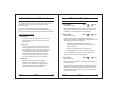
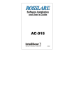
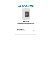
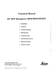
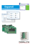
Mounting the AC-Q41SP Controller
Case Screw
Door LED
3 x 4 Matrix Keypad
Installation
1) Before starting, select the location to mount the AC-Q41SP
controller.
2) Drill holes into the back of the metal according to how you want
to mount the AC-Q41SP. (See explanation and diagram below).
US Gang Box
There are two hole indicators on the back of the metal cover
specifically for the US Gang Box. (Shown marked as A)
#
A
B
B
0
8
7
9
5
4
6
2
1
3
4 Screw Custom
There are four indicators on the back. (Shown marked as B)
CAUTION!
DO NOT DRILL
This is the Tamper Lens
C
B
B
(With BL-D40)
Bell Button
Mode LED
A
3) Screw the AC-Q41SP back cover to its mounting location.
4) Wire the controller according to the wiring instructions on the
following page.
AC-Q41SP
Page 9
03/04
5) Mount the AC-Q41SP to the back cover.
3) Trim and cover all conductors that are not used.
6) Secure the AC-Q41SP by using the supplied security screw in
the controllers accessories kit. An L-Shaped tool is provided for
use when tightening the security screw.
A few of the typical wiring diagrams are shown on the next three
pages; for other wiring diagram examples refer to the support
section of the Rosslare Web Site.
www.rosslaresecurity.com
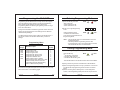
Wiring the AC-Q41SP
The controller is supplied with a 40” (1 m) pigtail, having a 10
conductor cable. To wire the AC-Q41SP, perform the following
steps.
1) Prepare the controller cable to the required length.
2) Splice the controller pigtail wires to the corresponding devices
and cover each connection. Refer to the wire color guide
provided below and to the wiring diagrams provided on the
following pages.
Wire Color Guide
COLOR
RED
BLACK
GREEN
WHITE
PURPLE
GRAY
BROWN
BLUE
YELLOW
ORANGE
AC-Q41SP
DESCRIPTION
V INPUT
GROUND
REX / BL
IN / MONITOR
LOCK: COM
N.O.
N.C.
AUX: COM
N.O.
N.C.
Page 10
03/04
AC-Q41SP
Page 11
03/04
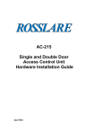
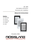
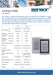
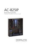
Wiring Diagrams
Wiring the Auxiliary Input and Output
Wiring the Lock Strike Relay and REX
AC-Q41SP
AC-Q41SP
{
N.O.
N.C.
COM
AUX.
GRAY
BROWN
PURPLE
GROUND
V IN
(+)
REX
(+)
(-)
(-)
WHITE
YELLOW
ORANGE
BLUE
BLACK
RED
COMMON
POWER SUPPLY
ELECTRIC LOCK
STRIKE
FAIL SAFE
or
FAIL SECURE
{
N.O.
N.C.
COM
IN / MONITOR
LOCK
IN / MONITOR
GREEN
AUX. IN
REX / BL
BLACK
RED
REX / BL
GROUND
V IN
12V - 24V DC
or
12V - 24V AC
COMMON
POWER SUPPLY
FROM TRANSFORMER
(-)
(+)
AUXILIARY INPUT
(MONITOR)
(-)
12V - 24V DC
or
(-)
12V - 24V AC
FROM TRANSFORMER
Auxiliary
Relay
N.C.
COM
N.O.
AC-Q41SP
Page 12
03/04
AC-Q41SP
Page 13
03/04
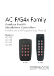
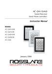
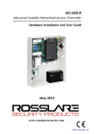
Wiring the BL-D40 External Sounder
THIS PAGE IS INTENTIONALLY BLANK
AC-Q41SP
GROUND
V IN
REX / BL
COMMON
POWER SUPPLY
BLACK
RED
GREEN
(-)
or
(+)
12V - 24V AC
(+)
(-)
FROM TRANSFORMER
REX / BL
12V - 24V DC
BL-D40
AC-Q41SP
Page 14
03/04
AC-Q41SP
Page 15
03/04
Modes of Operation
Normal, Secure, & Master Users
The AC-Q41SP accepts up to 500 users and provides entry via the
use of PIN codes. Each user is provided with two code memory
slots, Memory Slot 1 (Primary Code) and Memory Slot 2
(Secondary Code).
The way in which the two memory slots are programmed
determines a users access level and also determines the way in
which the AC-Q41SP grants access in its three Modes of Operation.
The AC-Q41SP has 3 Modes of Operation:
Mode
1) Normal Mode.
= Mode LED is green
Normal Mode is the default mode. In Normal Mode the door is
locked until a Primary Code is presented to the controller. The
controller can only be programmed in Normal Mode.
2) Bypass Mode.
l Mode LED is orange
There are three user levels:
Door
GREEN
Mode
Door
ORANGE
Normal User
In Bypass Mode, access to the premises is dependent on
whether the controller's Lock Strike Relay is programmed for Fail
Safe Operation or Fail Secure Operation.
A Normal User only has a Primary Code and is only
granted access when the AC-Q41SP is in Normal or
Bypass Mode.
When the Lock Strike Relay is programmed for
Fail Secure Operation, the door is locked until the star
button is pressed.
Secure User
A Secure User must have a Primary and Secondary
Code programmed, the two codes must not be the
same. The Secure User can gain access when the
AC-Q41SP is in any of its three Modes of Operation.
In Normal Mode the Secure User must use their
Primary Code to gain entry. In Secure Mode the
Secure User must first present their Primary and
then their Secondary Code in order to gain entry.
When the Lock Strike Relay is programmed for
Fail Safe Operation, the door is constantly unlocked.
In case of power failure, for security reasons when power is
restored the controller will be in Normal Mode.
3) Secure Mode.
l Mode LED is red
Master User
A Master User must have both Primary and
Secondary Codes programmed with the same
Proximity Card or PIN code. The Master User can
gain access during any Mode of Operation by
entering their PIN code to the controller.
AC-Q41SP
Page 16
Mode
Door
RED
Only Secure and Master Users can access the premises during
the Secured Mode.
A Secure User must enter their Primary and Secondary Codes to
gain entry. After entering their Primary code the Door LED will
flash green for 10 seconds, during which the Secondary Code
must be entered. A Master User only needs to enter their PIN
code once to gain entry.
03/04
AC-Q41SP
Page 17
03/04
Changing from Normal Mode to Bypass Mode:
Changing the Modes of Operation
By default there is no Normal / Bypass code. The Normal / Bypass
code must first be programmed to use this function. Refer to page
26 to create / modify the Normal / Bypass Code
Changing from Normal Mode to Secure Mode:
The default factory setting for the Normal / Secure Code is 3838
1) Enter the 4-digit Normal / Secure
Code
l
Mode
Door
Mode
Door
GREEN
GREEN
Mode
Mode LED will flash red
1) Enter the 4 digit Normal / Bypass
Code.
Door
l
Mode LED will flash orange
Mode
Door
ORANGE
RED
2) Press the "#" key to confirm
the Mode change.
l Mode LED is red
Mode
Door
RED
2) Press the "#" key to confirm
the Mode change.
l Mode LED will turn orange
Mode
Door
ORANGE
Changing from Bypass Mode to Normal Mode:
Changing from Secure Mode to Normal Mode:
1) Enter the 4 digit Normal / Bypass
Code.
Mode
Door
ORANGE
The default factory setting for the Normal / Secure Code 3838
l
1) Enter the 4-digit Normal / Secure
Code.
l
Mode LED will flash green.
Mode
Mode
Door
GREEN
RED
Mode
Door
GREEN
2) Press the "#" key to confirm
the Mode change.
l Mode LED will turn green.
Mode LED will flash green
Door
Mode
2) Press the "#" key to confirm
the Mode change.
l Mode LED will turn green
Mode
Door
GREEN
Door
Auxiliary Input and Output
GREEN
The Auxiliary Input of the AC-Q41SP can also be used to switch
the mode of operation from Secure to Normal Mode and vice
versa. Refer to "Setting the Auxiliary Mode" on Page 29.
The AC-Q41SP auxiliary input and output can be configured in ten
different modes of operation, for optimum usability in different
applications.
For more information, refer to “Setting the Auxiliary Mode" on
Page 29.
AC-Q41SP
Page 18
03/04
AC-Q41SP
Page 19
03/04
BL-D40 External Sounder
Request to Exit (REX) Button
The REX button must be located inside the premises to be secured
and is used to open the door without the use of a proximity card or
PIN code, it is usually located in a convenient location, e.g. beside
the door or at a receptionist's desk. The function of the REX button
depends on whether the Lock Strike Relay is programmed for Fail
Safe Operation or Fail Secure Operation. The door chime in the BLD40 does not sound when the REX button is used to open the door.
The BL-D40 External Sounder is designed to operate indoors and
installed within the premises to be secured. The Sounder can be
powered by 12 to 24V DC power supply or by 12 to 24V AC from a
transformer.
1) Fail Secure Operation: From the moment the REX button is
pressed, the door will be unlocked until the "Lock Strike Release
Time" has passed. After this time, the door will be locked even if
the REX button has not been released.
1) The Bell always sounds when the controller's door bell button
is pressed.
2) Fail Safe Operation: From the moment the REX button is
pressed, the door will be unlocked until the REX button is
released, plus the "Lock Strike Release Time". In this case the
"Lock Strike Relay" only begins its count down once the REX
button has been released. This feature is designed to keep the
door open when used in conjunction with fire systems.
The BL-D40 is capable of emitting four different types of alerts both
audible and visual; Bell, Door Chime, Siren, and Strobe Light.
2) The Door Chime can be programmed to sound whenever a valid
code is entered.
3) The Siren can be programmed to sound when the case of the
controller is tempered i.e. opened or when the controller is
removed from the wall. The controller can also program the
length of the Siren time in the BL-D40.
The Controller communicates with the BL-D40 using a coded
proprietary Rosslare communications protocol. This provides a
secure link between the Controller and the BL-D40.
Case and Back Tamper
If the case of the controller is opened or the controller is removed
from the wall, a tamper event is triggered. A coded tamper signal is
then sent to the BL-D40 or other compatible device.
If the BL-D40 receives any unrecognized codes on its
communication line or communication between the controller and
the BL-D40 are severed, the Strobe will flash repeatedly until the
communication problem has been resolved.
If the BL-D40 External Sounder receives a Tamper Event Signal, it
will activate a Siren and a Strobe Light. The Siren time can be easily
programmed in the AC-Q41SP from 0 to 9 minutes.
The tamper event can activate the Auxiliary Output if the controller
is in Auxiliary Mode 3. Refer to “Setting the Auxiliary Mode” on
page 29.
Clearing a tamper event is done by entering a valid User Code.
AC-Q41SP
Page 20
03/04
AC-Q41SP
Page 21
03/04
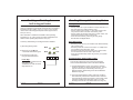
Programming the AC-Q41SP
Entering Programming Mode
Programming the AC-Q41SP is done solely via the unit's keypad
driven Programming Menu System. To reach the Programming
Menu System the AC-Q41SP must first be placed into
Programming Mode. See "Entering Programming Mode" on Page
23 for more information.
During the AC-Q41SP's manufacturing process certain codes and
settings are pre-programmed. These settings are the called the
"Default Factory Settings".
The table below shows the names of all the AC-Q41SP menus. It
also shows of all the AC-Q41SP’s default factory codes and
settings.
2580
0852
1234
3838
0004
2004
Menu Description
Change Open Code
Change Auxiliary Code
Change Program Code
Change Normal / Secure Code
Change Normal / Bypass Code
Change Door Release Time
Define Auxiliary Inputs / Outputs
Enroll Proximity Cards, PIN Code or both.
Delete Proximity Cards or PIN Code
Code Assignment with Strike/Auxiliary
Return to Default Factory Setting
2) Enter your 4-digit Programming
Code.
If the Programming Code
is valid the door LED will turn
green and the AC-Q41SP will be in
Programming Mode.
Mode
Door
RED
1
2
3
4
Mode
Door
GREEN
Note: - The AC-Q41SP must be in Normal Mode to enter the
Programming Mode.
- The factory default Programming Code is 1234
- If a Programming Code is not entered within 5 seconds,
The AC-Q41SP will return to Normal Mode.
Programming Menu
Factory
Settings
1) Press the "#" key two times
within 2 seconds.
l Mode LED will turn off
l Door LED will turn red
Menu
Number
1
2
3
4
5
6
6
7
8
9
0
Exiting Programming Mode
1) To exit the Programming Mode at any time:
Press the "#" key.
l You will hear 1 long beep
l The Door LED will be off
l The Mode LED will turn green
Mode
Door
GREEN
This indicates that the AC-Q41SP has returned to Normal Mode.
2) Wrong entries may reset the controller back to Normal Mode.
You will find a complete description and instructions for each of the
above menu items on the following pages.
3) While in Programming Mode if no key is pressed for 1 minute the
AC-Q41SP will exit programming mode and return to Normal
Mode.
4) While in enrolling users, deleting users, or code assignment
modes, to exit Programming Mode press the “#” key three times.
AC-Q41SP
AC-Q41SP
Page 22
03/04
Page 23
03/04
1) Enter Programming Mode
Changing the Open Code
Mode
The Open Code is mainly used as a method to quickly test the
Lock Strike Relay during installation.
2) Press "2" to enter Menu 2
l The Mode LED will turn orange
The Default Factory Setting for the Open Code is 2580.
When the first user is added to the controller, the default Open
Code will automatically be deleted, ready for a new Open Code
to be re-entered.
3) Enter the new 4-digit code you
wish to set as Auxiliary Code.
Mode
1) Enter Programming Mode
Door
GREEN
2) Press "1" to enter Menu 1
l The Mode LED will turn red
3) Enter the new 4-digit code you
wish to set as Open Code.
4) System returns to Normal Mode
l You will hear three beeps
l The Door LED will turn off
l The Mode LED will turn green
Mode
Door
RED
?
?
GREEN
?
Mode
?
4) System returns to Normal Mode
l You will hear three beeps
l The Door LED will turn off
l The Mode LED will turn green
Door
ORANGE GREEN
?
?
?
Mode
?
Door
GREEN
Note: - Auxiliary Code does not work in Secure Mode.
- Auxiliary Code only works when the Auxiliary Mode is
0, 1, 8 or 9.
- Code 0000 will erase and deactivate the Auxiliary
Code.
Changing the Programming Code
Mode
1) Enter Programming Mode
The Auxiliary Code is mainly used as a method to quickly test the
Auxiliary Relay during installation. The Default Factory Setting for
the Auxiliary Code is 0852.
For security reasons when the first user is added to the controller
or the open code is changed, the default Auxiliary Code will
automatically be deleted, ready for an Auxiliary Code to be
assigned.
03/04
Door
GREEN
2) Press "3" to enter Menu 3
l The Mode LED will turn green.
3) Enter the new 4-digit code you
wish to set as Programming Code
Changing the Auxiliary Code
Page 24
Mode
Door
GREEN
Note: - Open Code does not function in Secure Mode.
- Wrong entries: you will hear a long beep and the
controller will return to Normal Mode.
- Code 0000 will erase and deactivate the Open Code.
AC-Q41SP
Door
GREEN
4) System returns to Normal Mode
= You will hear three beeps
= The Door LED will turn off
= The Mode LED will turn green
Mode
Door
GREEN GREEN
?
?
Mode
?
?
Door
GREEN
Note: - Programming Code can not be erased, i.e. the code
0000 is not valid and will not erase the Programming
Code.
AC-Q41SP
Page 25
03/04
Changing the Normal / Secure Code
1) Enter Programming Mode
Mode
Door
GREEN
2) Press "4" to enter Menu 4
l The Mode LED will flash red
3) Enter the new 4-digit code you
wish to set as Normal / Secure Code
4) System returns to Normal Mode
l You will hear three beeps
l The Door LED will turn off
l The Mode LED will turn green
Mode
?
?
0
Enter the 4-digit code 0000
0
Enter the 4-digit code 0001
GREEN
?
0
0
0
0
1
?
0
?
0
c) Enable Bypass Code - Disable Door Chime
?
Enter any 4-digit code ending with 0
Mode
0
b) Disable Bypass Code - Enable Door Chime
Door
RED
a) Disable Bypass Code - Disable Door Chime
Door
GREEN
Changing the Normal / Bypass Code
and Door Chime Settings
?
d) Enable Bypass Code - Enable Door Chime
Enter any 4-digit code not ending with 0
Note: - When the Auxiliary Mode is 1, 2, 3, or 4 the Auxiliary
Input takes priority over the Normal / Secure Code.
?
4) System returns to Normal Mode
l You will hear three beeps
l The Door LED will turn off
l The Mode LED will turn green
?
Mode
?
Door
GREEN
Note: - The chime is only generated when the Lock
Strike Relay is activated due to a valid code entry.
The Normal / Bypass Code is also used to turn the Door Chime off
and on. Chime only functions with BL-D40 External Sounder.
1) Enter Programming Mode
Mode
Door
GREEN
2) Press "5" to enter Menu 5
l The Mode LED will flash orange.
Mode
Door
ORANGE GREEN
3) Below is a list of the four different ways that the Normal / Bypass
Code and Door Chime can be programmed.
a) Disable Bypass Mode - Disable Door Chime
b) Disable Bypass Mode - Enable Door Chime
c) Enable Bypass Mode - Disable Door Chime
d) Enable Bypass Mode - Enable Door Chime
AC-Q41SP
Page 26
03/04
AC-Q41SP
Page 27
03/04
Setting Fail Safe/Secure Operation
Setting Tamper Siren Time
Setting the Lock Strike Release Time
Setting the Auxiliary Mode
The default auxiliary setting is 2004.
Mode
1) Enter Programming Mode
Door
GREEN
The Tamper Siren feature requires the BL-D40 External Sounder.
Mode
1) Enter Programming Mode
Door
GREEN
2) Press "6" to enter Menu 6
l The Mode LED will flash green
3) Construct the 4-digit code
using the instructions below:
Mode
Door
GREEN
?
?
GREEN
?
Door
GREEN
2
?
GREEN
?
?
Auxiliary Setting
Auxiliary Mode
In addition to the Lock Strike Relay and Lock Strike REX, the
AC-Q41SP features an Auxiliary Output Relay and an Auxiliary
Input. The Auxiliary Mode defines the function of the Auxiliary
Input and Output.
The Auxiliary Mode also determines if the Auxiliary Output Relay
is set for Fail Safe or Fail Secure Operation.
Auxiliary Settings
Each of the Auxiliary Modes has a two digit setting that affects
how the Auxiliary Mode functions.
Third and Fourth Digit
Enter the number of seconds from
(1 to 99 seconds) that you want
the Lock Strike to be released.
For example 0 5 1 2 means Fail Secure Operation, with a 5
minute Tamper Siren Time, and a 12 second Lock Strike release
time.
Page 28
Mode
Auxiliary Mode
Second Digit
Tamper Siren Time, enter any
number from 0 to 9 minutes.
AC-Q41SP
3) Construct the 4-digit code
using the instructions below:
?
First Digit
For Fail Secure Operation the first
digit should be "0"
For Fail Safe Operation the first
digit should be "1"
4) System returns to Normal Mode
l You will hear three beeps
l The Door LED will turn off.
l The Mode LED will turn green
2) Press "6" to enter Menu 6
l The Mode LED will flash green
Mode
Door
GREEN
03/04
4) System returns to Normal Mode
l You will hear three beeps
l The Door LED will turn off.
l The Mode LED will turn green
Mode
Door
GREEN
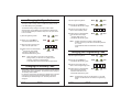
The Auxiliary Mode Quick Reference Table can be found on the
next page. For a more detailed explanation on each auxiliary mode
refer to the “Auxiliary Mode Reference Guide” on page 31.
AC-Q41SP
Page 29
03/04
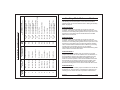
00 to 99 Shunt Time
00 to 99 Maximum Shunt Time
00 to 99 Forced Delay
00 to 99 Ajar Delay
01 to 99 Aux. Relay Release Time
00
Aux. Relay Toggles
01 to 99 Aux. Relay Release Time
00
Aux. Relay Toggles
N.O.
N.C.
N.C.
N.C.
N.O.
N.O.
Direct Shunt
Shunt
Forced Door
Door Ajar
Valid Code
Valid Code
Normal / Secure
Door Monitor
Door Monitor
Door Monitor
LED Ctrl - Red
LED Ctrl - Green
4
5
6
7
8
9
01 to 99 Aux. Relay Release Time
00
Aux. Relay activated by Tamper
N.C.
Tamper Event
Normal / Secure
3
01 to 99 Aux. Relay Release Time
00
Aux. Relay Toggles
N.O.
Star Button
Normal / Secure
2
01 to 99 Aux. Relay Release Time
00
Aux. Relay Toggles
N.O.
Valid Code
Normal / Secure
1
01 to 99 Aux. Relay Release Time
00
Aux. Relay Toggles
N.O.
Valid Code or REX-2
REX-2
0
Auxiliary Settings
(All times and delays are in seconds)
Aux.
Relay
Auxiliary Output
Activated On
Auxiliary Input
Function
Auxiliary
Mode
Auxiliary Mode Quick Reference Table
Auxiliary Mode Reference Guide
The following are brief descriptions of each of the AC-Q41SP's
auxiliary modes. To use these features refer to “Setting the Auxiliary
Mode” on page 29.
AUXILIARY MODE 0
In auxiliary mode 0 the AC-Q41SP can function as a two door
controller. The auxiliary relay should be attached to the lock on the
second door. The auxiliary setting defines the door open time for the
second door. The auxiliary input should be attached to the REX
button for the second door.
AUXILIARY MODE 1
In auxiliary mode 1 the AC-Q41SP can function as a two door
controller. The auxiliary relay should be attached to the lock on the
second door. The auxiliary setting defines the door open time for the
second door. The auxiliary input can switch the mode of operation
of the controller between Normal and Secure Mode. By connecting
a switch timer to the auxiliary input you can for example
automatically switch the AC-Q41SP from Normal Mode during office
hours to Secure mode after office hours.
AUXILIARY MODE 2
In auxiliary mode 2 the auxiliary relay can function as a general
purpose timed switch that can be activated when the star button on
the AC-Q41SP is pressed. The auxiliary setting defines how long
the auxiliary relay should be activated. The auxiliary input can
switch the mode of operation of the controller between Normal and
Secure Mode. By connecting a switch timer to the auxiliary input
you can for example automatically switch the AC-Q41SP from
Normal Mode during office hours to Secure mode after office hours.
AUXILIARY MODE 3
In auxiliary mode 3 the auxiliary output is activated if the AC-Q41SP
is tampered, i.e. the case tamper or back tamper is triggered. The
auxiliary input can switch the mode of operation of the controller
AC-Q41SP
Page 31
03/04
between Normal and Secure Mode. By connecting a switch timer to
the auxiliary input you can for example automatically switch the ACQ41SP from Normal Mode during office hours to secure mode after
office hours.
AUXILIARY MODE 4
In auxiliary mode 4 the AC-Q41SP is capable of shunting an alarm
system's door sensor. The auxiliary output should be wired in
parallel to the door sensor. When in use the auxiliary output is
normally open and the door sensor functions normally. When a
valid code is entered the auxiliary relay will shunt the door sensor
for the duration of the shunt time as defined by the auxiliary setting.
If the door is left open longer than the shunt time the alarm will be
triggered.
AUXILIARY MODE 5
In auxiliary mode 5 the AC-Q41SP is capable of shunting an alarm
system. In this mode the auxiliary input should be wired to the
magnetic contact switch on the door. The auxiliary relay should be
wired to the alarm system. Without a valid code entered the
auxiliary relay will match the condition of the magnetic contact
switch, if the door opens the auxiliary relay will open, if the door
closes the auxiliary relay will close. When a valid code is entered a
count down for maximum shunt time as defined in the auxiliary
setting begins, if the door is not closed before the maximum shunt
time, the alarm will be triggered.
AUXILIARY MODE 7
In auxiliary mode 7 the AC-Q41SP can trigger the auxiliary relay if it
detects that the door has been ajar too long. In this mode the
auxiliary input should be wired to the magnetic contact switch on the
door. The auxiliary relay should be wired to the alarm system. If the
door is opened the controller will wait for the door ajar delay time, if
the door does not close before the ajar delay time the controller will
activate the auxiliary relay. The auxiliary setting defines the door
ajar time.
If the BL-D40 is connected and an ajar event occurs the BL-D40 will
chime every few seconds for 1 minute or till the door is closed.
AUXILIARY MODE 8
In auxiliary mode 8 the AC-Q41SP can function as a two door
controller and also provide LED Control functionality. The auxiliary
relay should be attached to the lock on the second door. The
auxiliary setting defines the door open time for the second door. The
auxiliary input is used to control the LED. If the auxiliary input is
open the Door LED will flash red, if the auxiliary input is closed the
Door LED will flash green.
Note: This mode takes control of the Door LED. The Door LED will
no longer activate when a valid code is entered or when in
Secure Mode waiting for a Secondary Code to be entered.
AUXILIARY MODE 9
AUXILIARY MODE 6
In auxiliary mode 6 the AC-Q41SP can trigger the auxiliary relay if it
detects that the door has been forced. In this mode the auxiliary
input should be wired to the magnetic contact switch on the door.
The auxiliary relay should be wired to the alarm system. If the door
is forced open the controller will wait for the forced door delay time
and then activate the auxiliary relay. The auxiliary setting defines
the forced door delay.
In auxiliary mode 9 the AC-Q41SP can function as a two door
controller and also provide LED Control functionality. The auxiliary
relay should be attached to the lock on the second door. The
auxiliary setting defines the door open time for the second door. The
auxiliary input is used to control the LED. If the auxiliary input is
open the Door LED will flash green, if the auxiliary input is closed
the Door LED will flash red.
Note: This mode takes control of the Door LED. The Door LED will
no longer activate when a valid code is entered or when in
Secure Mode waiting for a Secondary Code to be entered.
AC-Q41SP
Page 32
03/04
AC-Q41SP
Page 33
03/04
Enabling or Disabling the
built in keypad heater
Enrolling Primary & Secondary Codes
Primary Codes
The AC-Q41SP contains a built-in keypad heater. When the keypad
heater is enabled the keypad heater will activate when the ambient
temperature drops to approx. 37°F to 41°F (3°C to 5°C) and will
remain active until the keypad temperate rises to approx 43°F to
48°F (6°C to 9°C).
When the heater is enabled the AC-Q42H’s lowest operating
temperature is -4°F (-20°C). When the heater is disabled the ACQ42H’s lowest operating temperature is 32°F (0°C).
Secondary Codes
The factory default setting for the keypad heater is disabled.
1) Enter Programming Mode
Mode
Door
GREEN
2) Press "6" to enter Menu 6
The Mode LED will flash green
Mode
Door
GREEN
3) Construct the 4-digit code
using the instructions below:
3
0
GREEN
0
- Primary Codes can only be enrolled to an empty User Slot, i.e a
slot where there is no existing Primary Code.
- Primary Codes must be unique, i.e. one users Primary Code
may not be the same as another users Primary Code.
- Primary Codes cannot be the same as any system codes, such
as the Normal / Secure Code or Open Code.
- Users who hold a Primary Code can gain entry during
Normal Mode and Bypass Mode.
?
- Secondary Codes can only be enrolled to User Slot that already
has a Primary Code.
- Secondary Codes do not have to be unique, i.e. multiple users
can all hold the same Secondary Code.
- Secondary Codes cannot be the same as any system codes,
such as the Normal / Secure Code or Open Code.
- Users who hold Secondary Codes can gain entry in any Mode
of Operation.
Enrolling Primary and Secondary Codes
Fourth Digit
To DISABLE the heater the fourth
digit should be "0"
To ENABLE the heater the fourth
digit should be "1”
There are two methods to enroll Primary and Secondary
codes, the Standard Method and the Code Search Method.
A. The Standard Method is mainly used when the User Slot
number for the user you wish to program is known. You can
program both Primary and Secondary Codes using the
Standard method. (See Enrolling Users with the Standard
Method on Page 36)
B. The Code Search Method is mainly used when enrolling a
users Secondary Code and the User Slot Code is unknown.
The Code Search method only works if a users Primary Code
is already enrolled but the Secondary Code is not. (See
Enrolling Users with the Code Search Method on Page 37)
AC-Q41SP
Page 34
03/04
AC-Q41SP
Page 35
03/04
Enrolling Secondary Codes using the Code Search
Method
Enrolling Primary and Secondary Codes using the
Standard Method
Mode
1) Enter Programming Mode
Door
GREEN
2) Press "7" to enter Menu 7
l The Door LED will turn orange
Mode
The Code Search feature enables you to quickly enroll a Secondary
Code to a user who’s slot number is unknown but who’s primary
code is known. .
Door
1) Enter Programming Mode
ORANGE
Mode
Door
GREEN
3) Enter the 3-digit User Slot number
? ?
between 001 to 500 that you wish to
enroll a Primary or Secondary code to.
For example, the User Slot 003 represents User #3.
?
2) Press "7" to enter Menu 7
l The Door LED will turn orange
Mode
3) Enter the 3-digit User Slot number 000
Mode
Door
4) a. If the selected slot has no
Primary Code, the Mode LED
GREEN GREEN
will flash green, indicating that
the controller is ready to accept a Primary Code.
Mode
Door
b. If the selected slot already has
a Primary Code but no
RED
GREEN
Secondary Code, the Mode LED
will flash red, indicating that the controller is ready to
accept a Secondary Code.
c. If the selected slot already has a Primary and Secondary
Code, you will hear a long beep and the controller will return
to Normal Mode.
5) Enter the 4-digit PIN that you want to assign as the Primary or
Secondary Code for this slot number.
If the PIN that is entered is valid the Mode LED will stop flashing
and then the controller is ready for you to enter the next 3 Digit
slot number (refer to step 3) that you want to assign a code to, or
press the "#" key to move to the next slot number (refer to step
4). If you do not wish to continue enrolling codes, press the "#"
key twice and the controller will return to Normal Mode.
AC-Q41SP
Page 36
03/04
l
The Door LED will flash orange
Door
ORANGE
0
Mode
0
0
Door
ORANGE
The controller is now waiting for the Primary Code of the User
you want to add a Secondary Code to.
.
4) Enter the 4 Digit PIN Code of the Primary Code belonging to the
user you want to add a Secondary Code to.
l
The Mode LED will flash red
Mode
Door
RED
ORANGE
If the Primary Code entered is not valid, you will hear a long beep
and the AC-Q41SP will continue to wait for a valid Primary Code.
5) Enter the 4-digit PIN Code to be used as the Secondary Code.
If the Secondary Code is valid the controller will beep three times
and return to Normal Mode.
If the Secondary Code is invalid the controller will make a long
beep and then the AC-Q41SP will continue to wait for a valid
Secondary code to be entered.
AC-Q41SP
Page 37
03/04
Deleting Primary & Secondary Codes
Deleting Primary and Secondary Codes using the Code Search
Method
There are two methods to delete Primary and Secondary codes, the
Standard Method and the Code Search Method.
1) Enter Programming Mode
When deleting a User Slot, both the Primary Code and the
Secondary code are erased.
2) Press "8" to enter Menu 8
l The Mode LED will turn red
Deleting Primary and Secondary Codes using the Standard
Method
3) Enter the 3-digit User Slot 000
Mode
1) Enter Programming Mode
Door
Mode
l
The Door LED will flash orange
Mode
Mode
0
l
?
The Mode LED will flash red
Indicating the controller is
waiting for the Programming
Code to confirm the deletion.
ORANGE
Mode
Door
ORANGE
The controller is now waiting for the Primary Code of the User
you want to delete.
?
?
Mode
Door
RED
4) Enter the 4-digit PIN Code of the
Primary Code belonging to the
user you want to delete.
?
?
The Mode LED will flash red
Mode
?
Door
RED
?
?
ORANGE
l
?
0
0
RED
If the User Slot is empty you will hear a long beep and the
AC-Q41SP will return to Normal Mode
4) Enter your Programming Code to
confirm the deletion.
ORANGE
Door
RED
3) Enter the 3-digit User Slot
codes you wish to delete.
Door
RED
GREEN
2) Press "8" to enter Menu 8
l The Mode LED will turn red
Door
GREEN
?
5) Enter your Programming Code to
confirm the deletion.
?
?
?
ORANGE
?
?
If the Programming Code is valid, you will hear three beeps
and the AC-Q41SP will return to Normal Mode.
If the Programming Code is valid, you will hear three beeps
and the AC-Q41SP will return to Normal Mode.
If the Programming Code is invalid, you will hear a long beep and
the AC-Q41SP will return to Normal Mode.
If the Programming Code is invalid, you will hear a long beep and
the AC-Q41SP will return to Normal Mode.
Note: - It is recommended that a record be kept of added and
deleted users so that it will be easier to keep track of
which user slots are empty and which user slots are not.
Note: - It is recommended that a record be kept of added and
deleted users so that it will be easier to keep track of
which user slots are empty and which user slots are not.
AC-Q41SP
Page 38
03/04
AC-Q41SP
Page 39
03/04
Lock Strike Relay and Auxiliary Relay
Code Assignment
When a Primary Code is enrolled for any user, that user is assigned
rights to activate the Lock Strike Relay when they present a valid
code to the controller. The Code Assignment Menu allows you to
assign whether the Lock Strike Relay and/or the Auxiliary Relay is
activated when a user enters a valid code
There are two methods to Assign Codes, Standard Method and the
Code Search Method.
Lock Strike and Auxiliary Relay Code Assignment using the
Code Search Method
Mode
1) Enter Programming Mode
2) Press "9" to enter Menu 9
l The Mode LED will turn red
Mode
Mode
Door
GREEN
2) Press "9" to enter Menu 9
l The Mode LED will turn green
Mode
Door
GREEN ORANGE
3) Enter the 3-digit User Slot that
you want to assign a code to.
?
?
?
Door
GREEN ORANGE
3) Enter the 3-digit User Slot 000
l
The Door LED will flash orange
0
0
0
Mode
Door
GREEN ORANGE
Lock Strike Relay and Auxiliary Relay Code Assignment using
the Standard Method
1) Enter Programming Mode
Door
GREEN
The controller is now waiting for the Primary Code of the user
you want to Code Assign
4) Enter the 4-digit PIN Code of the
Primary Code belonging to the user
you want to assign a code to.
l
The Mode LED will flash green
?
?
Mode
?
?
Door
GREEN ORANGE
l
The Door LED will flash green
Mode
Door
GREEN ORANGE
5) Enter the assignment digit for the current User Slot:
4) Enter the assignment digit for the current User Slot:
"1" assigns the Lock Strike Relay only
"2" assigns the Auxiliary Relay only
"3" assigns the Lock Strike and Auxiliary Relay
"1" assigns the Lock Strike Relay only
"2" assigns the Auxiliary Relay only
"3" assigns the Lock Strike and Auxiliary Relay
l
If the assignment code is valid
the Mode LED will stop flashing.
Mode
Door
GREEN ORANGE
The controller is now waiting for another slot number. Press the
"#" key to go to the next slot or enter a new slot number, or if
you do not wish to continue press the "#" key twice and the
controller will return to Normal Mode.
AC-Q41SP
Page 40
03/04
If the assignment digit is valid, you will hear three beeps and
then the controller will return to Normal Mode.
If the assignment digit is invalid, you will hear a long beep and
the controller will wait for another assignment digit to be entered.
AC-Q41SP
Page 41
03/04
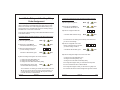
Return To Factory Default Settings
Warning:
You must be very careful before using this command!
Doing so will erase the entire memory which includes
all User and Special Codes, and return all codes to
their factory defaut settings.
Mode
1) Enter Programming Mode
Door
3) Enter your 4-digit Programming
Code.
Mode
Door
RED
?
?
RED
?
Note: The AC-Q41SP must be in Normal Mode otherwise this
will not work. Make sure that the Mode LED is green
before proceeding.
1) Remove power from the AC-Q41SP
2) Press the REX button
3) Apply power to the unit with REX button pressed
4) Release the REX button
GREEN
2) Press "0" to enter Menu 0
l The Mode LED will flash red
l The Door LED will flash red
Replacing a lost Programming Code
5) You now have 15 seconds to program a new Programming Code
into the unit using the initial default code 1234, before the
controller reverts to the existing code.
?
l
If the Programming Code is valid, all memory will be erased,
you will hear three beeps and the controller will return to
Normal Mode
l
If the Programming Code is invalid you will hear a long beep
and the controller will return to Normal Mode without erasing
the memory of the controller.
Replacing a lost Normal / Secure Code
Note: The AC-Q41SP must be in Secure Mode otherwise this
will not work. Make sure that the Mode LED is red before
proceeding.
1) Remove power from the AC-Q41SP
2) Press the REX Button
3) Apply power to the unit with REX button pressed.
4) Release the REX Button
5) You now have 15 seconds to use the default Normal / Secure
code 3838 in order to return to normal mode, where you may
enter programming mode to program a new Normal / Secure
Code.
AC-Q41SP
Page 42
03/04
AC-Q41SP
Page 43
03/04
F
Glossary
A
Access Control: Primarily refers to
a device or set of devices controlling
the entry of people traveling through
a door or set of doors.
Ajar Delay: The time allowed for a
door to be left open before sounding
an alert and / or activating the
Auxiliary Relay.
Amplitude Shift Keying (ASK): The
type of data communications
between the Proximity Card and the
Proximity Reader.
ASK: An abbreviation of "Amplitude
Shift Keying".
Auxiliary Input: The term used for
the programmable input electrical
signal from an external device such
a Door Monitor switch or Auxiliary
REX button.
Auxiliary Code: The four digit code
used to activate the Auxiliary Output
for testing purposes during
installation.
Auxiliary Output: The term used for
the Relay Output in the AC-Q41SP
that may be programmed to activate
upon different system events such as
Tamper, Forced Door Event, Door
Ajar, etc.
B
Back Tamper: The electronic
tamper signal advising the controller
that the controller has been removed
from the wall.
Bypass Code: The four digit code
used to change the Mode of
Operation of the AC-Q41SP from
Normal to Bypass Mode or vice
versa.
Bypass Mode: A Mode of Operation
where door access is not restricted to
AC-Q41SP
valid users. In this mode the door
may be released by anyone pressing
the star button.
C
Case Tamper: The electronic
tamper signal advising the controller
that the case has been opened.
Code Assignment: The process of
assigning which Output(s) (Lock
Strike Relay and / or Auxiliary Relay)
are to be activated when a valid code
is entered.
D
Direct Shunt: The arrangement in
which an external input (such as a
door monitor) is connected directly to
the Auxiliary Relay allowing the
Auxiliary Output to be activated after
the direct shunt delay elapses. This
leaves the Auxiliary Input available
for Normal / Secure mode toggle.
Default Factory Setting: The
settings that the controller is
preprogrammed with when the
controller is manufactured.
Direct Shunt Delay: The delay time
(user programmed) used in Direct
Shunt (See Direct Shunt).
Door Bell: The alert sound activated
when the door star button on the ACQ41SP is pressed. (Requires the BLD40 External Sounder)
Door Chime: The alert sound
activated when the lock strike
unlocks the door after a valid code
has been presented. (Requires the
BL-D40 External Sounder)
Page 44
03/04
Fail Safe: The system setting in
which a total power loss leaves the
connected door unlocked.
Fail Secure: The system setting in
which a total power loss leaves the
connected door locked.
Forced Door: A door which has been
physically opened without the access
control device having released the
lock.
Forced Door Time: The amount of
time (user programmed) the
controller waits in the event of a
Forced Door before the Auxiliary
Output is activated.
L
Lock Strike: Term used for the
electronic or electromagnetic door
lock used for locking or unlocking the
door.
Lock Strike Release Time: The
amount of time (user programmed)
that the Lock Strike remains
unlocked when a valid code is
entered.
M
Master User: A user which has a
Primary and Secondary Code which
are the same, and can gain access in
any Mode of Operation.
Mode of Operation: The state of
operation of the controller. There are
three "Modes": Normal Mode,
Bypass Mode, and Secure Mode.
N
versa.
Normal / Secure Code: The four
digit code used to change the
controllers Mode of Operation from
Normal to Secure Mode or vice
versa.
Normal User: A user who only has a
Primary Code and can only gain
access in Normal Mode.
Normally Closed: A relay output
from the controller that is activated
(closed circuit) under normal
conditions.
Normally Open: A relay output from
the controller that is de-activated
(open circuit) under normal
conditions.
O
Open Code: The four digit code used
to activate the Lock Strike Relay for
testing purposes during installation.
P
Primary Code: The unique code
issued to enable access in Normal
Mode. Users with only primary codes
are Normal Users.
Programming Code: The four digit
code required when entering
programming mode, deleting users,
and resetting the AC-Q41SP to its
factory default settings.
Programming Mode: The mode
used when programming the ACQ41SP’s system settings.
Proximity Cards: A contactless
(RFID) identification card each with
unique code.
Normal Mode: The system setting
(Mode of Operation) in which all valid
users have access upon presenting a
valid PIN Code (Primary Code).
Normal / Bypass Code: The four
digit code used to change the
controllers Mode of Operation from
Normal to Bypass Mode or vice
AC-Q41SP
Page 45
03/04
R
T
Relay: An electronically controlled
switch used for providing an Open
Circuit or Closed Circuit output to
external devices.
REX: An abbreviation of "Request
To Exit".
Request To Exit (REX): Refers to a
button which can release the door
from inside. Commonly located at the
reception desk, or near a door as an
emergency door release.
Tamper Siren: The alert sound
activated when a Back Tamper or
C a s e Ta m p e r e v e n t o c c u r s .
(Requires the BL-D40 External
Sounder)
Tamper Siren Time: The time (user
programmed) that the Tamper Siren
will sound when activated.
Warranty of Rosslare's products extends to the original purchaser of
the Rosslare product and is not transferable.
Secondary Code: An additional
code issued to enable access in
Secured Mode. Users with nonidentical Primary and Secondary
Codes are Secure Users. Users with
identical Primary and Secondary
Codes are Master Users.
Secure Mode: The system setting
(Mode of Operation) in which only
valid Secure and Master Users have
access upon presenting a valid code.
Secure User: A user which has a
Primary Code and Secondary Code
that are non-identical, and can gain
access in any Mode of Operation.
Shunt: The arrangement in which an
external input (such as a door
monitor) is connected to the Auxiliary
Input, allowing the auxiliary output to
be activated after the Shunt Delay
elapses.
Shunt Delay: Is the delay time (user
programmed) used in Shunt (See
Shunt).
Strike: See Lock Strike
Page 46
,,
ROSSLARE ENTERPRISES LIMITED S (Rosslare) LIMITED
LIFETIME WARRANTY is applicable worldwide. This warranty
supersedes any other warranty. Rosslare's LIMITED LIFETIME
WARRANTY is subject to the following conditions:
WARRANTY
S
AC-Q41SP
Limited Lifetime Warranty
WARRANTY DURATION
Rosslare warrants this product against defects in material and/or
workmanship for the life of the product from the date of original
purchase to the original purchaser.
WARRANTY COVERAGE
Rosslare will repair or replace, at its option, any product which
under normal conditions of use and service proves to be defective
in material or workmanship. No charge will be made for labor or
parts with respect to defects covered by this warranty, provided that
the work is done by Rosslare or a Rosslare authorized service
center. This warranty does not cover expenses incurred in the
transportation, removal or reinstallation of the product, whether or
not proven defective. Replacement or repairs furnished under this
warranty are subject to the same terms and conditions of the
original warranty.
EXCLUSIONS AND LIMITATIONS
Specifically excluded from this warranty are failures caused by
abuse, neglect, misuse, improper operation, normal wear, accident,
improper maintenance or modification. This warranty does not cover
repair or replacement where normal use has exhausted the life of a
part or instrument. Service life of the product is dependent upon the
care it receives and the conditions under which it has to operate. In
no event shall Rosslare be liable for incidental or consequential
damages.
03/04
AC-Q41SP
Page 47
03/04
LIMITED LIFETIME WARRANTY TERMS
The terms of this warranty may not be varied by any person,
whether or not purporting to represent or act on behalf of Rosslare.
This warranty represents the full extent of Rosslare's
responsibility. Repair, replacement, or refund of the original
purchase price, of the product is the exclusive remedy. This
limited lifetime warranty is provided in lieu of all other
warranties. All other warranties expressed or implied,
including without limitation, implied warranties of
merchantability and fitness for a particular purpose, are
specifically excluded. In no event shall Rosslare be liable for
damages in excess of the purchase price of the product, or for
any other incidental, consequential or special damages,
including but not limited to loss of use, loss of time,
commercial loss, inconvenience, and loss of profits, arising
out of the installation, use, or inability to use such product, to
the fullest extent that any such loss or damage may be
disclaimed by law. This warranty shall become null and void in the
event of a violation of the provisions of this limited warranty.
Technical Support
International:
Rosslare Enterprises Ltd.
905-912 Wing Fat Industrial Bldg.,
12 Wang Tai Road, Kowloon Bay,
Hong Kong.
www.rosslare.com.hk/support
Tel:
Fax:
E-mail:
(852) 2795 5630
(852) 2795 1508
[email protected]
United States and Canada:
Rosslare NAPDC
Suite 238, 200 East Howard Street,
Des Plaines, IL 60018
USA
www.rosslaresecurity.com
Tel:
Tel:
Fax:
E-mail:
AC-Q41SP
Page 48
03/04
AC-Q41SP
(866) 262 8633 (Toll-Free)
(847) 827 6330 (Direct)
(847) 827 6433
[email protected]
Page 49
03/04