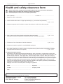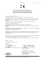
1
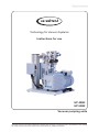
page 1 of 20 Technology for Vacuum Systems Instructions for use HP 40B2 HP 63B2 Vacuum pumping units Documents are only to be used and distributed completely and unchanged. It is strictly the users´ responsibility to check carefully the validity of this document with respect to his product. Manual-no.: 999069 / 24/09/2014 page 2 of 20 Dear customer, Your VACUUBRAND pumping unit is designed to provide you with many years of trouble-free service with optimal performance. Our many years of practical experience allow us to provide a wealth of application and safety information. Please read these instructions for use before the initial operation of your pumping unit. VACUUBRAND vacuum pumps combine our many years of experience in design, construction and practical operation, with the latest developments in material and manufacturing technology. Our quality maxim is the ”zero defect” principle: Every vacuum pumping unit, before leaving our factory, is tested intensively, including an endurance run of 24 hours. Any faults, even those which occur rarely, are identified and can be eliminated immediately. After completion of the endurance run, every pumping unit is tested, and must achieve specifications before shipment. We are committed to providing our customers only pumps that meet this high quality standard. While our pumps cannot eliminate all of your work, we design, manufacture and test them to ensure that they will be an effective and trouble-free tool to assist you in that work. Yours, VACUUBRAND GMBH + CO KG After sales service: Contact your local dealer or call +49 9342 808-5500. The document ”Safety information for vacuum equipment” is part of this manual! Read the ”Safety information for vacuum equipment” and observe the instructions contained therein! Trademark index: VACUU•LAN® (US-Reg.No 3,704,401), VACUU•BUS®, VACUU•CONTROL®, Peltronic®, VARIO® (USReg.No 3,833,788), VACUUBRAND® (US-Reg.No 3,733,388) and also the shown company logos are trademarks of VACUUBRAND GMBH + CO KG in Germany and/or other countries. Documents are only to be used and distributed completely and unchanged. It is strictly the users´ responsibility to check carefully the validity of this document with respect to his product. Manual-no.: 999069 / 24/09/2014 page 3 of 20 Contents Safety information!......................................................................................................4 General information.............................................................................................................................4 Intended use........................................................................................................................................4 Setting up and installing the equipment..............................................................................................5 Ambient conditions..............................................................................................................................6 Operating conditions...........................................................................................................................6 Safety during operation.......................................................................................................................7 Maintenance and repair.......................................................................................................................8 Technical data............................................................................................................10 Pump parts....................................................................................................................................... 11 Use and operation.....................................................................................................14 Setting up and installing...................................................................................................................14 Getting started..................................................................................................................................14 During operation...............................................................................................................................15 Shutdown.........................................................................................................................................16 Accessories...............................................................................................................16 Troubleshooting........................................................................................................16 Maintenance...............................................................................................................16 Notes on return to the factory..................................................................................17 Health and safety clearance form............................................................................18 EC Declaration of Conformity of the Machinery ........................................................19 ➨ DANGER indicates a hazardous situation which, if not avoided, will result in death or serious injury. + WARNING indicates a hazardous situation which, if not avoided, could result in death or serious injury. • NOTICE CAUTION indicates a hazardous situation which, if not avoided, could result in minor or moderate injury. NOTICE is used to address practices not related to personal injury. Caution! Hot surface! Disconnect equipment from AC power. Documents are only to be used and distributed completely and unchanged. It is strictly the users´ responsibility to check carefully the validity of this document with respect to his product. Manual-no.: 999069 / 24/09/2014 page 4 of 20 Safety information! General information + Read this manual carefully before installing or operating the equipment. Observe the instructions contained in this manual. ☞ Read the manuals of the rotary vane pump and of the diffusion pump before installing or operating the equipment. Observe the instructions contained in those manuals. ☞ Do not use any damaged equipment. • NOTICE Use the handles when moving the pump. Remove all packing material from the packing box. Remove the product from its packing-box and retain all packaging until the equipment is inspected and tested. Remove the protective caps from the inlet and outlet ports and retain for future use. Inspect the equipment promptly and carefully. If the equipment is damaged, notify the supplier and the carrier in writing within three days. Retain all packing material for inspection. State the item number of the product together with the order number and the supplier’s invoice number. Failure to check and give notice of damage will void any and all warranty claims for those deficiencies. Replace the protective caps, if the equipment is not used immediately. Store the equipment in dry and non-corrosive conditions. Intended use ☞ Do not use the pump or any system parts on humans or animals. ☞ Ensure that the individual components are only connected, combined and operated according to their design and as indicated in the instructions for use. Use only original manufacturer’s spare parts and accessories. Otherwise the safety and performance of the equipment, as well as the electromagnetic compatibility of the equipment might be reduced. The CE mark may be voided if not using original manufacturer’s spare parts. ☞ Comply with all notes on correct vacuum and electrical connections; see section “Use and operation“. ☞ The pumps are designed for ambient temperatures during operation between +12°C and +40°C. Periodically check maximum temperatures if installing the pump in a cabinet or a housing. Make sure ventilation is adequate to maintain recommended operating temperature. Install an external automatic ventilation system if necessary. If pumping hot process gases, make sure that the maximum permitted gas inlet temperature is not exceeded. The maximum permitted gas inlet temperature depends on several parameters like inlet pressure and ambient temperature (see ”Technical Data”). ☞ Particles and dust must not enter the pump. ☞ Do not pump liquids. NOTICE Use the equipment only as intended, that is, for generation of vacuum in vessels designed for that purpose. Any other use will automatically invalidate all warranty and liability claims. Remain aware of safety and risks. Documents are only to be used and distributed completely and unchanged. It is strictly the users´ responsibility to check carefully the validity of this document with respect to his product. Manual-no.: 999069 / 24/09/2014 page 5 of 20 Setting up and installing the equipment ➨ Equipment must be connected only to a suitable electrical supply and a suitable ground point. As such, the plug must be plugged into an outlet that is properly grounded. Failure to connect the motor to ground may result in deadly electrical shock. The supply cable may be fitted with a molded European IEC plug or a plug suitable for your local electrical supply. The cable contains wires color coded as follows: green or green and yellow: ground; blue or white: neutral; brown or black: hot. ☞ Due to the high compression ratio, the pump may generate overpressure at the outlet. Check pressure compatibility with system components (e.g., exhaust pipeline or exhaust valve) at the outlet. ☞ Do not permit any uncontrolled pressurizing. Make sure that the exhaust tubing cannot become blocked to avoid a risk of bursting! ☞ Keep the electrical power cord away from heated surfaces. • Provide a firm, level platform for the equipment. Check that the system which you are going to evacuate is mechanically stable. Check that all fittings are secure. Ensure a stable position of the pumping unit. • Comply with maximum permissible pressures at inlet and outlet and with maximum permissible pressure differences between inlet and outlet. See section “Technical data“. Do not operate the pump with overpressure at the inlet. • Avoid overpressure of more than 1.2 bar absolute in the event that inert gas is connected to the pump, to the gas ballast or to a venting valve. • • • Note: Flexible elements will shrink when evacuated. Connect hoses gas tight at inlet and outlet of the pump. Ensure that no foreign objects can be drawn into the pump. • Check the power source and the pump’s rating plate to be sure that the power source and the equipment match in voltage, phase, and frequency. • Use only oil of the recommended type. Other oils or operating fluids may cause damage of the pump or danger. Use special oils for the rotary vane pump, if, e.g., - the pump operates in the vicinity of potential ignition sources. - oxygen or other flammable gases account for a large proportion of the evacu ated gases. • Under normal operation conditions, pump oils and lubricants are not toxic and their use entails no danger. Certain hazards are, however, associated with some of these products. • Take adequate precautions when handling pump fluids, lubricants, and solvents. Use appropriate protective clothing, safety goggles and protective gloves to avoid excessive contact with the skin and possible skin irritations (including dermatitis). Do not inhale or swallow. Maintain adequate levels of hygiene and cleanliness. Ensure that the pump location is well ventilated and that possible toxic effects of certain vapors are avoided. • Comply with all relevant statutory requirements and regulations concerning the handling, storage and disposal of oil. Attention! Do not allow oils to be poured into or enter the drainage system or other bodies of water. Spillage can cause accidents, use suitable means of removing spilled oil. Documents are only to be used and distributed completely and unchanged. It is strictly the users´ responsibility to check carefully the validity of this document with respect to his product. Manual-no.: 999069 / 24/09/2014 page 6 of 20 NOTICE Make sure ventilation is adequate to maintain recommended operating temperature. Keep a minimum distance of 5 cm between the cooling fans and surrounding items (e.g., housing, walls, etc.), or else install an external automatic ventilation system. Check fans regularly for dust/dirt. Clean fan guard grills if necessary to avoid a reduction of ventilation. Use only hoses at the inlet and outlet of the pump with an inner diameter at least as large as the diameter of the pump’s tubing (to avoid overpressure at the outlet, and reduction of pumping speed at the inlet). Allow the equipment to equilibrate to ambient temperature if you bring it from cold environment into a room prior to operation. Notice if there is water condensation on cold surfaces. The ON/OFF-switches are located at the terminal box. At first, switch on the rotary vane pump (backing pump), then switch on the diffusion pump. The diffusion pump can be switched on only if the backing pump has been switched on. Comply with all applicable and relevant safety requirements (regulations and guidelines). Implement the required actions and adopt suitable safety measures. Ambient conditions NOTICE • Adopt suitable measures in case of differences from recommended conditions, e.g., using the equipment outdoors, installation in higher altitudes, conductive pollution or external condensation on the pump. • Do not operate this product near flames. To the best of our knowledge the equipment is in compliance with the requirements of the applicable EC-directives and harmonized standards (see ”Declaration of Conformity”) with regard to design, type and model. Directive EN 61010-1 gives in detail the conditions under which the equipment can be operated safely (see also IP degree of protection). Operating conditions ➨ These pumps are not approved for operation in potentially explosive atmospheres. Do not operate the pumps in potentially explosive atmospheres. ➨ These pumps are not approved for the pumping of potentially explosive atmospheres. Do not pump potentially explosive atmospheres. ➨ The pumps are not suitable to pump any of the substances listed below. Do not pump: - unstable substances - substances which react explosively under impact (mechanical stress) without air - substances which react explosively when being exposed to elevated temperatures without air, - substances subject to auto-ignition, - substances which are inflammable without air - explosive substances. ➨ The pumps are not approved for operation below ground. Do not operate the pump below ground. Documents are only to be used and distributed completely and unchanged. It is strictly the users´ responsibility to check carefully the validity of this document with respect to his product. Manual-no.: 999069 / 24/09/2014 page 7 of 20 • • • Do not pump substances which may form deposits inside the pump. The pumps are not suitable for pumping substances which may form deposits inside the pump. Deposits and con�������������������������������������������������� densate in the pump may lead to increased temperatures even to the point of exceeding the maximum permitted temperatures. Deposits may cause seizing of the pump unit. Check the inlet and outlet of the pump and its oil condition, if there is a danger of forming deposits or corrosion inside the pump, e.g., in the pump unit. Inspect the pump regularly and clean if necessary. In case, replace corroded parts or change pump oil. Consider interactions and chemical reactions of the pumped media. Ensure that the materials of the pump’s wetted parts are compatible with the pumped substances, see section ”Technical data”. When changing the substances pumped, we recommend purging the pump with air or inert gas prior to changing the pumped media. Purging the pump will pump out residues and it will reduce the possibility of reactions of the pumped substances with each other and with the pump’s materials or with the pump oil. If necessary change oil before changing the pumped media. Safety during operation ➨ Adopt suitable measures to prevent the release of dangerous, toxic, explosive, corrosive, noxious or polluting fluids, vapors and gases. To prevent any emission of such substances from the pump outlet, install an appropriate collecting and disposal system and take protective action for pump and environment. ➨ You must take suitable precautions to prevent any formation of explosive mixtures inside the pump, in the oil reservoir, or at the outlet of the pump. In such circumstances, mechanically generated sparks, hot surfaces or static electricity may ignite these mixtures. Use inert gas for gas ballast or venting, if necessary. ➨ Drain appropriately or otherwise remove any potentially explosive mixtures at the outlet of the pump, or dilute them to non-explosive concentrations. ➨ Never operate this pump if it has a damaged cord or plug. ☞ Prevent any part of the human body from coming into contact with vacuum. + If there is an exhaust isolation valve, make sure that you cannot operate the equipment with the valve closed to avoid a risk of bursting! + Always provide a free and pressureless exhaust outlet to avoid damage to the pump and risk of bursting. ☞ Comply with applicable regulations when disposing of chemicals. Take into consideration that chemicals may be contaminated. Take adequate precautions to protect people from the effects of dangerous substances (chemicals, oil mist, thermal decomposition products of fluoroelastomers). Use appropriate protective clothing and safety goggles. ☞ Interruption of the pumping unit or of a pump (e.g., due to power failure), failure of connected components or of parts of the supply, or change in parameters must not be allowed to lead to dangerous conditions. In case of a leak in the manifold or at the shaft seal, pumped substances might be released into the environment or into the pump housing or motor. Comply with all notes regarding proper use of the pumps, as well as operation and maintenance guidance. Documents are only to be used and distributed completely and unchanged. It is strictly the users´ responsibility to check carefully the validity of this document with respect to his product. Manual-no.: 999069 / 24/09/2014 page 8 of 20 ☞ The residual leak rate of the equipment might render possible an exchange of gas, albeit extremely slight, between the environment and the vacuum system. Adopt suitable measures to prevent contamination of the pumped substances or the environment. • • Ensure that no parts of your clothing, hair or fingers can be caught or drawn in at the inlet of the pump. Never insert fingers or drop any other object into the inlet or outlet. Pumping at high inlet pressure may lead to overpressure at the gas ballast valve. Pumped gases or condensate might be expelled if the valve is open. If an inert gas supply is connected to the gas ballast, ensure that its inlet pipeline is not contaminated. • Pay attention to the safety symbol ”hot surfaces” on the equipment. Hot parts may cause burns if touched. Adopt suitable measures to prevent any danger arising from hot surfaces or electric sparks. During normal operation the diffusion pump becomes very hot, especially the vacuum connection. Do not touch, risk of burning! Avoid contacting or covering the pump with burnable material, or material which may be damaged due to high temperature, e.g., electrical power cord. Ensure that hot surfaces of the pump do not cause burns. Provide a suitable contact guard if necessary. NOTICE Attention: If the maximum permissible inlet pressure or the backing pressure at the diffusion pump are exceeded, pump fluid might enter other parts of the vacuum system. Provide appropriate protective measures to allow for the possibility of failure and malfunction. The protective measures must also allow for the requirements of the respective application. In case of overload, the motor of the rotary vane pump is shut down by a self-hold thermal cutout in the winding. Note: Only manual reset is possible. Switch off the pump and disconnect from the power source. Identify and eliminate the cause of failure. Allow the pump to cool down sufficiently before restart. In case of excess temperature the motor of the diffusion pump is shut down by a safety switch. • Attention: After cooling down, the heating of the diffusion pump restarts automatically. Adopt suitable measures if a restart is a potential source of danger. Maintenance and repair In order to comply with laws (occupational, health and safety regulations, safety at work law and regulations for environmental protection) vacuum pumps, components and measuring instruments can only be returned when certain procedures (see section ”Notes and return to the factory”) are followed. ➨ Ensure that the pump cannot be operated accidentally. Never operate the pump if covers or other parts of the pump are disassembled. ➨ Switch off the pump. Disconnect the electrical power cord and wait two minutes before starting maintenance to allow the capacitors to discharge. ➨ Note: The pump may be contaminated with process chemicals, which have been pumped during operation. Ensure that the pump is completely decontaminated Documents are only to be used and distributed completely and unchanged. It is strictly the users´ responsibility to check carefully the validity of this document with respect to his product. Manual-no.: 999069 / 24/09/2014 page 9 of 20 before maintenance commences. ☞ Take adequate precautions to protect people from the effects of dangerous substances if contamination has occurred. Use appropriate protective clothing, safety goggles and protective gloves. ☞ Wear parts have to be replaced regularly. ☞ Never operate a defective or damaged pump. ☞ Vent the pumping unit before starting maintenance. Isolate the pumping unit and other components from the vacuum system. Allow sufficient cooling of the pump. Drain condensate, if applicable. NOTICE Ensure that maintenance is done only by suitably trained and supervised technicians. Ensure that the maintenance technician is familiar with the safety procedures, which relate to the products processed by the pumping system. Documents are only to be used and distributed completely and unchanged. It is strictly the users´ responsibility to check carefully the validity of this document with respect to his product. Manual-no.: 999069 / 24/09/2014 page 10 of 20 Technical data ☞ See manuals of the rotary vane pump and of the diffusion pump as well. HP 40B2 / RZ 2.5 Type Backing pump HP 40B2 / RZ 6 RZ 2.5 RZ 6 Recommended oil for backing pump VACUUBRAND B-oil Diffusion pump AX 65 Recommended pump fluid for diffusion pump diffusion pump oil for VACUUBRAND oil diffusion pump Pump fluid capacity of diffusion pump ml Maximum pumping speed l/s Ultimate vacuum* HP 63B2 30 22 mbar 37 < 1 x 10⁻⁶ Maximum permissible inlet / outlet pressure (absolute) bar 1.1 Maximum pressure difference between inlet and outlet bar 1.1 Maximum permissible pressure (absolute) at gas ballast valve bar 1.2 Maximum permissible temperature of gaseous media continuous operation: 40°C, for short periods (less than 5 minutes): up to 80°C Permissible ambient temperature storage / operation °C -10 to +60 / +12 to +40 Permissible relative atmospheric moisture during operation % 30 to 85 (no condensation) Maximum permissible installation altitude above mean sea level m 2000 Maximum permissible range of supply voltage Rated input current: 230 V~ 50/60 Hz Power draw 230 V~ 50/60 Hz 230V~ ±10% 50/60Hz A VA 2.7 / 2.2 3.2 / 3.2 621 / 506 736 / 736 Degree of protection IEC 529 IP 10B Inlet small flange KF DN 40 Outlet hose nozzle DN 10 mm A-weighted emission sound pressure dB(A) level** (uncertainty KpA: 3 dB(A)) Dimensions L x W x H approx. Weight approx. clamping flange ISO-K DN 63 mm kg 42 49 445 x 385 x 435 445 x 381 x 460 25.4 30.9 * If the pumping unit is running with fresh oil (oil has been changed or topped up), a running time of up to two days might be necessary to achieve the ultimate vacuum. This effect is due to the normal outgassing of the oil. ** Measurement according to EN ISO 2151:2004 and EN ISO 3744:1995 at 230V/50Hz and at ultimate vacuum with exhaust tube at outlet. Documents are only to be used and distributed completely and unchanged. It is strictly the users´ responsibility to check carefully the validity of this document with respect to his product. Manual-no.: 999069 / 24/09/2014 page 11 of 20 Pump parts Position Component Position Component 1 Diffusion pump AX 65 9 Inlet 2 Backing pump RZ 2.5 10 Outlet 3 Backing pump RZ 6 11 Fore-vacuum valve V1 4 ON/OFF switch diffusion pump 12 By-pass valve V2 5 ON/OFF switch backing pump 13 High vacuum valve V3 6 Rating plate of pumping unit 14 Venting valve V4 7 Connection diagram 15 8 Handle Connection for vacuum gauge KF DN 10 We reserve the right for technical modification without prior notice! HP 40B2 / RZ 2.5 15 5 9 13 14 6 11 1 12 7 10 4 2 8 Documents are only to be used and distributed completely and unchanged. It is strictly the users´ responsibility to check carefully the validity of this document with respect to his product. Manual-no.: 999069 / 24/09/2014 page 12 of 20 HP 40B2 / RZ 6 15 5 9 13 14 11 6 12 1 10 7 4 3 8 ☞ An oil mist filter for installation at the outlet of the rotary vane pump RZ 6 is separately packed. Pay attention to the notes on assembling the oil mist filter in the assembly instructions „Accessories for rotary vane pumps“. Documents are only to be used and distributed completely and unchanged. It is strictly the users´ responsibility to check carefully the validity of this document with respect to his product. Manual-no.: 999069 / 24/09/2014 page 13 of 20 HP 63B2 15 5 13 9 14 6 11 12 1 10 7 4 3 8 Documents are only to be used and distributed completely and unchanged. It is strictly the users´ responsibility to check carefully the validity of this document with respect to his product. Manual-no.: 999069 / 24/09/2014 page 14 of 20 Use and operation Setting up and installing ☞ Make sure ventilation is adequate, especially if the pump is installed in an enclosure, or if the ambient temperature is elevated. Provide external ventilation, if necessary. • • • NOTICE Reduce the transmission of vibration. Prevent mechanical load due to rigid pipelines. Insert elastic hoses or flexible elements as couplings between the pump and rigid pipes. Note: Flexible elements will compress or flatten when evacuated if not designed for use under vacuum. Hose connections at the pump inlet must always be gas tight. If the pump is installed at an altitude of more than 2000 m above mean sea level, check compatibility with applicable safety requirements, and adopt suitable measures. There is a risk of the motor overheating due to insufficient cooling. Keep a minimum distance of 5 cm between cooling fans and surrounding items (e.g., housing, walls, etc.), or else install an external automatic ventilation system. Use connecting hoses with large diameter and keep them as short as possible to avoid flow losses. Locate the pump as closely as possible to the application. Always install outlet tubing descending from the pump or provide other measures to avoid backflow of condensate towards the pump. Getting started NOTICE Proceed strictly according to the given order and comply with the given time and pressure data. Switching on the pumping unit (pump and vacuum vessel at atmospheric pressure) ➨ Open fore-vacuum valve (V1). Close by-pass valve (V2), high vacuum valve (V3), and venting valve (V4). ➨ Switch on backing pump (rotary vane pump RZ 2.5 or RZ 6), switch on diffusion pump. ☞ The diffusion pump can be switched on only once the backing pump has been switched on. ➨ Close fore-vacuum valve (V1) after the heating time (approx. 15 minutes) has elapsed and the fore-vacuum (M1) is below 0.1 mbar. ➨ Open by-pass valve (V2). ➨ Close by-pass valve (V2) once the pressure inside the vacuum vessel is below 0.1 mbar. ➨ Open fore-vacuum valve (V1). ➨ Open high vacuum valve (V3). ☞ Note: If the fore-vacuum (M1) rises above 0.1 mbar, close the high vacuum valve (V3) and pump down with the backing pump to a pressure below 0.1 mbar. ☞ If the thermal cutout of the rotary vane pump has tripped, it is imperative that the high vacuum valve (V3) be closed and the diffusion pump switched off! Documents are only to be used and distributed completely and unchanged. It is strictly the users´ responsibility to check carefully the validity of this document with respect to his product. Manual-no.: 999069 / 24/09/2014 page 15 of 20 Venting the vacuum vessel ➨ Close high vacuum valve (V3). ➨ Close by-pass valve (V2) (if not closed). ➨ Open venting valve (V4). Pumping down again Close venting valve (V4). Close fore-vacuum valve (V1). Open by-pass valve (V2). Close by-pass valve (V2) once the pressure inside the vacuum vessel is below 0.1 mbar. ➨ Open fore-vacuum valve (V1). ➨ Open high vacuum valve (V3). ☞ Note: If the fore-vacuum (M1) rises above 0.1 mbar, close the high vacuum valve (V3) and pump down with the backing pump to a pressure below 0.1 mbar. ➨ ➨ ➨ ➨ ☞ If the thermal cutout of the rotary vane pump has tripped, it is imperative that the high vacuum valve (V3) be closed and the diffusion pump switched off! Vacuum connection diagram: M1 M2 V3 V4 V1 P2 V2 F0 P1 P2 V1 V2 V3 V4 M1 M2 F0 Backing pump Diffusion pump Fore-vacuum valve By-pass valve High vacuum valve Venting valve Measuring point 1 Measuring point 2 Oil mist filter P1 During operation ☞ Maximum ambient temperature: 40 °C Check the maximum temperatures, if installing the pump in a cabinet or a housing. Make sure ventilation is adequate, especially if the ambient temperature is elevated. • Check the oil level of the rotary vane pump and the pump fluid level of the diffusion pump every time before starting the pump, however at least once a week. Check the oil and pump fluid levels more frequently if high amounts of gas or vapor are pumped. Documents are only to be used and distributed completely and unchanged. It is strictly the users´ responsibility to check carefully the validity of this document with respect to his product. Manual-no.: 999069 / 24/09/2014 page 16 of 20 • A power failure may cause accidental ventilation of the pumping unit, especially if the gas ballast valve of the rotary vane pump is open. If this constitutes a potential source of danger, take appropriate safety measures. Shutdown NOTICE Proceed strictly according to the given order and comply with the given time data. Stopping the evacuation process and venting the vacuum vessel: ➨ Close high vacuum valve (V3). In case open venting valve (V4) to vent the vacuum vessel. ➨ Switch off diffusion pump. ➨ Keep the backing pump running for another 30 to 45 minutes. ➨ Close fore-vacuum valve (V1). ➨ Switch off backing pump. ☞ Attention: Never switch off the backing pump together with the diffusion pump. Proceeding in accordance with the instructions given above ensures that the diffusion pump is kept under vacuum (no condensate build-up in the pump fluid). To avoid possible formation of condensate in the pump housing it is advisable to keep the pump or the pumping system under vacuum even after shutdown. Accessories Vacuum gauge DCP 3000 with gauge head VSP 3000 (Pirani)..................................................683190 1*103 - 1*10-3 mbar, 100-230 V 50-60 Hz Gauge head MPT 200 Penning/Pirani, 1*103 - 5*10-9 mbar.........................................................683177 Troubleshooting ☞ See manuals of the rotary vane pump and of the diffusion pump. Maintenance ☞ See manuals of the rotary vane pump and of the diffusion pump. Notes on filling the pump fluid into the diffusion pump: It is also possible to fill the pump fluid through the valve into the inlet flange of the diffusion pump. ➨ Open valve plate and fill in the pump fluid between cold cap and pump housing (approx. 30 ml). Documents are only to be used and distributed completely and unchanged. It is strictly the users´ responsibility to check carefully the validity of this document with respect to his product. Manual-no.: 999069 / 24/09/2014 page 17 of 20 Notes on return to the factory Repair - return - DAkkS calibration NOTICE Safety and health of our staff, laws and regulations regarding the handling of dangerous goods, occupational health and safety regulations and regulations regarding safe disposal of waste require that for all pumps and other products the “Health and safety clearance form“ must be send to our office fully completed and signed before any equipment is shipped to the authorized service center. Fax or mail a completed copy of the health and safety clearance form to us in advance. The declaration must arrive before the equipment. Enclose a second completed copy with the product. If the equipment is contaminated, you must notify the carrier. No repair / DAkkS calibration is possible unless the correctly completed form is returned. Inevitably, there will be a delay in processing the equipment if information is missing, or if this procedure is not followed. If the product has come in contact with chemicals, radioactive substances or other substances dangerous to health or environment, the product must be decontaminated prior to sending it back to the service center. - Return the product to us disassembled and cleaned and accompanied by a certificate verifying decontamination or - Contact an industrial cleaning and decontamination service directly or - Authorize us to send the product to an industrial cleaning facility at your expense. To expedite repair and to reduce costs, please enclose a detailed description of the problem and the product’s operating conditions with every product returned for repair. We submit repair quotations only on request and always at the customer’s expense. If an order is placed, the costs incurred for problem diagnosis are offset from the costs for repair or from the purchase price, if the customer prefers to buy a new product instead of repairing the defective one. - If you do not wish a repair on the basis of our quotation, the equipment may be returned to you disassembled and at your expense. In many cases, the components must be cleaned in the factory prior to repair. For cleaning we use an environmentally friendly water based process. Unfortunately the combined attack of elevated temperature, cleaning agent, ultrasonic treatment and mechanical stress (from pressurised water) may result in damage to the paint. Please mark in the health and safety clearance form if you wish a repaint at your expense just in case such a damage should occur. We will also replace parts for cosmetic reasons at your request and at your expense. NOTICE Before returning the equipment ensure that (if applicable): - Oil sealed pumps: Oil has been drained and an adequate quantity of fresh oil has been filled in to protect against corrosion. Dispose according to regulations. - Equipment has been cleaned and/or decontaminated (inside and outside). - All inlet and outlet ports have been capped. - Equipment has been properly packed, (if necessary, please order original packaging materials at your costs), marked appropriately and notify the carrier of any possible contamination. - The completed health and safety declaration is enclosed. We thank you in advance for your understanding the necessity for these measures that protect our employees, and ensure that your device is protected in shipment. Scrapping and waste disposal: Dispose of the equipment and any components removed from it safely in accordance with all local and national safety and environmental requirements. Particular care must be taken with components and waste oil which have been contaminated with dangerous substances from your processes. Do not incinerate fluoroelastomer seals and O-rings. - You may authorize us to dispose of the equipment at your expense. Documents are only to be used and distributed completely and unchanged. It is strictly the users´ responsibility to check carefully the validity of this document with respect to his product. Manual-no.: 999069 / 24/09/2014 page 18 of 20 Health and safety clearance form Devices will not be accepted for any handling before we have received this declaration. Please read and comply with ”Notes on return to the factory”. Oil filled pumps: Drain oil prior to shipping absolutely! 1. Device (Model): ................................................................... 2. Serial no.: ......................................... 3. Reason for return / malfunction: .............................................................................................................................................................. 4. Has the device been used in a copper process step (e.g., semiconductor production). ☐ yes ☐ no 5. Substances (gases, liquids, solids) in contact with the device / which have been pumped: .............................................................................................................................................................. .............................................................................................................................................................. .............................................................................................................................................................. .............................................................................................................................................................. 6. Prior to return to the factory the device has been decontaminated. ☐ yes ☐ no Description of the decontamination method and the test / verification procedure: .............................................................................................................................................................. .............................................................................................................................................................. 7. The device is free of hazardous, harmful substances. ☐ yes ☐ no 8. Protective measures required for VACUUBRAND employees: .............................................................................................................................................................. 9. If the paint is damaged, we wish a repaint or a replacement of parts for reason of appearance (repaint and replacement at customer’s expense). ☐ yes ☐ no 10.Legally binding declaration We assure for the returned device that all substances, which have been in contact with the device are listed in section 5 and that the information is complete and that we have not withheld any information. We declare that all measures - where applicable - have been taken listed in section “Return to the factory”. By our signature below, we acknowledge that we accept liability for any damage caused by providing incomplete or incorrect information and that we shall indemnify VACUUBRAND from any claims as regards damages from third parties. We are aware that as expressed in § 823 BGB (Public Law Code of Germany) we are directly liable for injuries or damages suffered by third parties, particularly VACUUBRAND employees occupied with handling/repairing the product. Shipping of the device must take place according to regulations. Name: ....................................................................... Signature: .............................................................. Job title: .................................................................... Company’s seal: Date: ....................................................................... Release for repair grant by VACUUBRAND (date / signature): .............................................................. VACUUBRAND GMBH + CO KG Tel.: +49 9342 808-5660 Alfred-Zippe-Straße 4 Fax: +49 9342 808-5666 Documents are only to be used and distributedE-Mail: completely and unchanged. It is strictly the users´ responsibility to check carefully 97877 Wertheim, Germany [email protected] the validity of this document with respect to his product. Manual-no.: 999069 / 24/09/2014 www.vacuubrand.com page 19 of 20 EG-Konformitätserklärung für Maschinen EC Declaration of Conformity of the Machinery Déclaration CE de conformité des machines Hersteller / Manufacturer / Fabricant: VACUUBRAND GMBH + CO KG · Alfred-Zippe-Str. 4 · 97877 Wertheim · Germany Hiermit erklärt der Hersteller, dass die Maschine konform ist mit den Bestimmungen der Richtlinie 2006/42/EG. Hereby the manufacturer declares that the machinery is in conformity with the directive 2006/42/EC. Par la présente, le fabricant déclare, que la machine est conforme à directive 2006/42/CE. Pumpstand / Pumping unit / Groupe de pompage: Typ / Type / Type: HP 40B2 / HP 63B2 Artikelnummer / Order number / Numéro d‘article: 699029, 2612089 / 699037 Seriennummer / Serial number / Numéro de série: Siehe Typenschild / See rating plate / Voir plaque signalétique Die Maschine ist konform mit weiteren Richtlinien / The machinery is in conformity with other directives / La machine est conforme à d’autres directives: 2006/95/EG, 2004/108/EG, 2011/65/EU Angewandte harmonisierte Normen / Harmonized standards applied / Normes harmonisées utilisées: DIN EN 12100:2011, DIN EN 61010-1:2010 (Ed. 3), DIN EN 1012-2:2011, DIN EN 61326-1:2013, DIN EN 50581:2013 Bevollmächtigter für die Zusammenstellung der technischen Unterlagen / Person authorised to compile the technical file / Personne autorisée à constituer le dossier technique: Dr. J. Dirscherl · VACUUBRAND GMBH + CO KG · Alfred-Zippe-Str. 4 · 97877 Wertheim · Germany Wertheim, 24.09.2014 ............................ Ort, Datum / place, date / lieu, date ............................ (Dr. F. Gitmans) Geschäftsführer / Managing director / Gérant ppa. ................................. (Dr. J. Dirscherl) Technischer Leiter / Technical Director / Directeur technique VACUUBRAND GMBH + CO KG Alfred-Zippe-Str. 4 · 97877 Wertheim T +49 9342 808-0 · F +49 9342 808-5555 [email protected] www.vacuubrand.com Documents are only to be used and distributed completely and unchanged. It is strictly the users´ responsibility to check carefully the validity of this document with respect to his product. Manual-no.: 999069 / 24/09/2014 page 20 of 20 Disclaimer: Our technical literature is only intended to inform our customer. The validity of general empirical values and results obtained under test conditions for specific applications depend on a number of factors beyond our control. It is therefore strictly the users´ responsibility to very carefully check the validity of application to their specific requirements. No claims arising from the information provided in this literature will, consequently, be entertained. VACUUBRAND GMBH + CO KG -Technology for Vacuum Systems- © 2014 VACUUBRAND GMBH + CO KG Printed in Germany Alfred-Zippe-Str. 4 · 97877 Wertheim / Germany T +49 9342 808-0 · F +49 9342 808-5555 [email protected] · www.vacuubrand.com Documents are only to be used and distributed completely and unchanged. It is strictly the users´ responsibility to check carefully the validity of this document with respect to his product. Manual-no.: 999069 / 24/09/2014