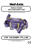
1
US008646474B2
(12) United States Patent
(10) Patent N0.2
Pearson
(54)
(45) Date of Patent:
AUTOMATED CONDENSATE DRAIN LINE
CLEANING SYSTEM, METHOD AND KIT
5,069,042 A
5,151,685 A
Inventor:
5,293,894 A
Steven L. Pearson, Aust1n, TX (US)
(Us)
( * ) Notice:
*
5,366,004 A
(73) Assignee: VisioneX Holdings, LLC, Austin, TX
12/1993
Popelka et al. ............. .. 137/112
3/1994
Fleischmann ............... .. 137/135
11/1994 Gamer et a1‘
5,416,947 A
5/1995 Jaffe
5,837,147 A
11/1998 Joung
6,024,112 A *
2/2000
6,041,611 A
3/2000 Palmer
patent
Subject‘istoexten
any diisglaimeé,
e or a Juste
the germ
unif
erthis
35
6,321,773 B1
Q1
1
11/2001
Ramsby
U.S.C. 154(b) by 435 days.
6,427,458 B1
8/2002 Fowler
(21) Appl. No.: 12/951,987
(22)
Filed
.
(65)
CornWell .................... .. 137/204
(Commued)
NOV 22 2010
.
Feb. 11, 2014
12/1991 stuchlik, III
9/1992 splceret a1~
5,271,237 A *
.
(75)
US 8,646,474 B2
FOREIGN PATENT DOCUMENTS
,
W0
Prior Publication Data
WO 2012/110800
8/2012
OTHER PUBLICATIONS
US 2011/0061745 A1
Mar. 17, 2011
apc.c0m, “NetworkAIR PA 1000 Installation (User’s Manual)”,
Related Us‘ Application Data
(62)
http://WWW.apcmedia.com/salestools/ASTE-6Z2RQ6iR0iEN.
pdf, (Apr. 2001), 28 pages.
Division of application No. 12/006,325, ?led on Dec.
_
31, 2007, noW Pat. No. 7,857,004.
(Commued)
(51)
Int Cl
Primary Examiner * Kevin Lee
Attorney, Agent, 0}’
i
(52)
U 5 Cl
Zafman LLP
USPC ...................................... .. 137/15.04; 137/240
(57)
(58)
SOkOlOff Taylor &
ABSTRACT
Field of Classi?cation Search
_
_
_
_
USPC .............. .. 137/1, 624.11, 624.12, 204, 15.04,
137/1505’ 488’ 240’ 238
Automated Condensate dram 11116 Cleamng apparatus are d15
closed. In one aspect, an apparatus may include a controller,
See application ?le for Complete Search history
a ?uid supply line, and at least one ?uid ?oW regulation
References Cited
device. The at least one ?uid ?oW regulation device may be
electrically coupled With the controller to receive at least one
control signal from the controller. The at least one ?uid ?oW
US. PATENT DOCUMENTS
regulation device may cause a ?uid to ?oW into a condensate
(56)
drain line through the ?uid supply line responsive to the at
2
52321818
430633317 A
12/1977 Santore
4,937,559 A
4,962,778 A
least one control signal. Other apparatus as Well as methods
and kits are 21150 disclosed.
6/1990 Meacham et al.
10/ 1990 Driskill
10 Claims, 8 Drawing Sheets
A LITOMA TED CONDENSATE
DRAIN LINE CLEANING SYSTEM
210
CONTROL
SIGNAL
FLUID FLOW
REGULATION
23”
CONTROLLER
m
DEVICE
242
245
‘- — — — ~ ~ — —|
ELLUD FLOW244 INTO
CONDENSATE DRAIN
LINE
AIR
1 CONDITIONING '
‘
|' * * — — ~ e —|
I CONDENSATE
_ _ _ _ _ _ _ _ _ __ _ _'
SYSTEM
DISCHARGE
LOCATION
CONDENSATE DRAIN
LINE 220
'
US 8,646,474 B2
Page 2
(56)
References Cited
U_S_ PATENT DOCUMENTS
2002/0157708 A1
10/2002 Goff
2005/0005625 A1
I/2005 Lee
2006/0033630 A1
2006/0042292 A1
2/2006 Lyall, III
3/2006 Kimbrough et a1.
6,442,955 B1
9/2002 Oakner et a1‘
2006/0070658 A1
4/2006 Nakata et a1.
6,442,956 B1
9/2002 Herren
2006/0096307 A1
5/2006 Coogle
6,443,173 B1*
9/2002 Thompson, Jr. ................ .. 137/1
2006/0096638 A1
5/2006 coogle
2006/0096639 A1
5/2006 Coogle
6,708,717 B1
6,730,865 B1
6,976,367 B2
6,992,259 B1
3/2004 coogle
5/2004 HernandeZ-Zelaya
12/2005 Spanger
2pm?“
,
,
7,392,658 B1
7,844,367 B2*
7,930,898 B2
2002/0000093 A1
OTHER PUBLICATIONS
I/2006 Cantolino
ooge
7/2008 Hardy, HI
11/2010 Nickerson et a1. ..... .. 137/62411
4/2011 Laufenberg et a1.
1/2002 Lea
Matsushita Eletrical Co. Ltd., “Room Air Conditioner Operating
-
n
Instructions ,
,
-
-
http.//serv1ce.us.panason1c.com/OPERMANPDF/
CSC9CKPG~PDFKZOOZLZ4 PageS~
* cited by examiner
US. Patent
Feb. 11,2014
Sheet 1 of8
US 8,646,474 B2
AUTOMATED CONDENSATE
DRAIN LINE CLEANING
METHOD
100
— 102
PERFORM AUTOMATED INTRODUCTION
OF FLUID INTO CONDENSATE DRAIN LINE
V
REMOVE AT LEAST ONE OF MICROBIAL
MATERIAL AND N ON-MICROBIAL DEBRIS /— 104
FROM CONDENSATE DRAIN LINE BY
FLOWING FLUID THROUGH CONDENSATE
DRAIN LINE
FIG. 1
US. Patent
Feb. 11,2014
Sheet 3 of8
US 8,646,474 B2
CONTROLLER OF AUTOMATED
CONDENSATE DRAIN LINE CLEANING
SYSTEM
QQQ
MATERIAL REMOVAL TIME
DETERMINATION LOGIC/UNIT
?iQ
USER
INPUT
USER INPUT DEVICE
(E. G., BUTTON, SWITCH,
DIAL KNOB ETC)
'
’
355
>
'
CONTROLLER 0F
AUTOMATED
CONDENSATE DRAIN
LINE CLEANING SYSTEM
T62
330
FI G. 313
US. Patent
Feb. 11,2014
Sheet 8 of8
US 8,646,474 B2
AUTOMATED CONDENSATE DRAIN LINE
CLEANING KIT @
CONTROLLER
5512
AT LEAST ONE FLUID FLOW
REGULATION DEVICE
51412
INSTRUCTIONS
$_8_5
F
'
AT LEAST ONE OTHER
COMPONENT
|
|
'
(OPTIONAL)
|
I
FIG. 8
US 8,646,474 B2
1
2
AUTOMATED CONDENSATE DRAIN LINE
CLEANING SYSTEM, METHOD AND KIT
damage. For example, the condensate may damage the ?oors,
Walls, carpet, and miscellaneous other content Within the
The present application is a divisional of US. patent appli
cation Ser. No. 12/006,325, ?led on Dec. 31, 2007, entitled
business or residence. In some cases, the condensate may
cause an electrical short. Sometimes such damage may con
tinue to occur unnoticed for days. This tends to be exacer
“AUTOMATED CONDENSATE DRAIN LINE CLEAN
ING SYSTEM, METHOD, AND KIT”, now US. Pat. No.
bated by the fact that air conditioners are often deployed in
attics, closets, or other out-of-sight locations.
7,857,004. Application Ser. No. 12/006,325 is hereby incor
porated herein by reference.
One approach is to have a plumber come out either from
time to time or after discovering the condensate over?oW and
associated damage. The plumber typically disconnects the
BACKGROUND
clogged condensate drain line, and manually removes the
microbial matter and/or debris from the condensate drain line
1. Field
Embodiments of the invention relate to air conditioning
systems. In particular, embodiments of the invention relate to
systems, methods, and kits to clean condensate drain lines of
(for example With compressed air from a compressed air
tank). Potential disadvantages of this approach are not pre
venting the condensate over?oW and associated damage and/
or the signi?cant costs of the plumber.
US. Patent Application Publication US 2006/0042292 dis
cusses another approach. As discussed in the abstract thereof,
air conditioning systems.
2. Background Information
Air conditioning systems are Widely utiliZed in homes and
businesses throughout the World. The air conditioning sys
20
currently, there are no products available Which alloW a user
tems, or air conditioners for short, are used to cool air in order
to solely remove microbial and bacterial groWth inside a
to provide a cool Working or living environment.
By Way of example, an air conditioner may have an evapo
blocked HVAC condensate drain line using compressed air
Without cutting into or disassembling the drain line. Our valve
rator or evaporator coils that are used to cool the air. In cooling
the air, humidity or Water vapor in the air may condense on the
is an in-line condensate drain line valve that can be installed
25
easily, quickly and economically, either during neW construc
relatively cooler evaporator coils. This may produce liquid
tion or onto existing HVAC systems. The HVAC user can
Water knoWn as condensation. Generally, the greater the
remove microbial and bacterial groWths Without cutting into
humidity, the greater the amount of condensation produced.
The air conditioner typically includes a primary conden
through the valve. The design of our valve alloWs the user to
sate drain pan situated beloW the evaporator coils to collect
the condensation. When the air conditioner is operating, con
densation may form on the evaporator coils, fall from the
or disassembling the drain line by injecting compressed air
30
evaporator coils into the primary condensate drain pan, and
accumulate in the condensate drain pan.
The air conditioner typically also includes a condensate
drain line. The condensate drain line may be used to drain the
condensate from the primary condensate drain pan to a suit
able destination, such as, for example, a seWer, an outside
location, or the like.
One challenge is that the condensate drain line may tend to
35
US. Pat. No. 6,041,611 discusses a system and method for
40
the condensate is insuf?cient to ?ush or otherWise remove the
microbial matter and/or non-microbial debris from the con
densate drain line. Eventually, if actions are not taken, this
groWth may tend to close off the condensate drain line and
prevent further How of condensate from the condensate drain
pan. This may cause the level of condensate in the condensate
With an air-conditioner that contains an evaporator coil and a
45
50
55
drain pan to rise.
Some air conditioners have a secondary or backup conden
sate drain line at a higher level in the condensate drain pan
than the aforementioned main condensate drain line. HoW
ever, this secondary condensate drain line may also become
clogged. If the air conditioner doesn’t have a secondary con
densate drain line, or if the secondary condensate drain line
also becomes clogged, the primary condensate drain pan may
?ll With condensate and at some point the condensate may
begin to over?oW.
In some cases, this condensate may over?oW into the busi
ness or residence and may tend to cause signi?cant property
cleaning air conditioning drains. As discussed in the abstract
thereof, a system for cleaning-out a condensate drain line is
disclosed. The condensate drain line is operatively associated
become clogged thereby restricting How of the condensate
from the primary condensate drain pan. One potential cause is
microbial groWth. Bacteria, algae, or other microbial matter
may tend to groW Within the condensate drain line. Non
microbial debris, such as, for example, dust, dirt, rust, or the
like, may also tend to enter the condensate drain line and
contribute to restriction of How.
Generally, the How rate of the condensate through the
condensate drain line is fairly loW. Typically, the How rate of
perform safe and routine maintenance to the HVAC drainage
system Without having to resort to expensive and repetitive
service call repairs over the lifetime of the HVAC system. The
valve is further designed to prevent undesirable reverse air
?oWs into the HVAC system and home or building, caused by
a dry trap in the condensate drain. The prevention of reverse
air?oWs and reduction of microbial and bacterial groWth Will
have a positive impact of Indoor Air Quality.
60
primary drain pan. The system comprises a manifold opera
tively placed in ?uid communication With the condensate
drain line. The manifold includes a ?rst, second, and third
line. In one embodiment, the ?rst line extends from the mani
fold, and the second and third line are axially aligned With the
condensate drain line. The system further includes a ?rst
valve member disposed Within the ?rst line, a second valve
member disposed Within the second line, and a third valve
member disposed Within the third line. A Water stream, Which
is operatively connected With the ?rst line, is provided so that
the Water stream may be channeled through the manifold and
into the condensate drain line. The manifold may further
comprises a fourth line extending from the center of the
manifold, With the fourth line having a fourth valve disposed
therein. The system may further comprise sensor means,
operatively associated With a secondary pan, for measuring
the level of condensation Within the secondary pan and acti
vating an alarm once a predetermined level is reached. A
method of cleaning a condensate drain line is also disclosed.
65
One potential draWback With all three of these approaches
is that manual actions, in some cases requiring special skills
or knoWledge, seem to be needed to remove the material from
the condensate drain line.
US 8,646,474 B2
4
3
BRIEF DESCRIPTION OF THE SEVERAL
VIEWS OF THE DRAWINGS
Then, at least one of microbial material and non-microbial
debris may be removed from the condensate drain line by
?oWing the ?uid through the condensate drain line, at block
104. The non-microbial debris may include dust, dirt, rust, or
the like, or a combination thereof. By Way of example, the
The invention may best be understood by referring to the
following description and accompanying draWings that are
used to illustrate embodiments of the invention. In the draW
microbial material and/ or non-microbial debris may be
ings:
removed to a seWer line, an outside location, a bucket, or other
suitable destination.
Advantageously, such a method may help to remove mate
rial from the condensate drain line. This may help to prevent,
or at least reduce, the likelihood, of condensate over?oW and
its associated damage. Accordingly, this method aims to pro
vide a preventative solution that may help to prevent property
FIG. 1 is a block ?oW diagram of an automated condensate
drain line cleaning method, according to embodiments of the
invention.
FIG. 2 is a block diagram of an automated condensate drain
line cleaning system, according to embodiments of the inven
tion.
damage from occurring.
FIG. 3A is a block diagram of a controller of an automated
Furthermore, the automated introduction of a ?uid into the
condensate drain line may help to reduce the involvement
and/or technical knoWledge requirements of the user. Indeed,
condensate drain line cleaning system, the controller having
cleaning time determination logic, according to embodiments
of the invention.
FIG. 3B is a block diagram of a user input device electri
cally coupled With, or otherWise in communication With, a
controller of an automated condensate drain line cleaning
system to provide user input to activate an automated clean
in some embodiments the level of automation may be such
that the user may barely even need to be aWare of the opera
20
or that the condensate drain pan could even over?oW.
FIG. 2 is a block diagram of an automated condensate drain
line cleaning system 210, according to embodiments of the
ing, according to embodiments of the invention.
FIG. 4 is a block diagram of an automated condensate drain
line cleaning system, according to ?rst embodiments of the
25
invention.
FIG. 5 is a block diagram of an automated condensate drain
line cleaning system, according to second embodiments of
the invention.
FIG. 6 is a block diagram of an automated condensate drain
invention.
An air conditioning system 215, a condensate drain line
220, and a condensate discharge location 225 (e.g., a seWer,
outside location, bucket, or the like) are shoWn. These com
ponents are shoWn in this ?gure to illustrate the coupling of
the automated condensate drain line cleaning system. HoW
30
line cleaning system, according to third embodiments of the
invention.
ever, these components are shoWn in dashed lines to indicate
that they are generally not a part of the automated condensate
drain line cleaning system.
The automated condensate drain line cleaning system 210
FIG. 7 is a block diagram of a vehicle having an automated
condensate drain line cleaning system, according to embodi
ments of the invention.
FIG. 8 is a block diagram of an automated condensate drain
tion of the automated condensate drain line cleaning system,
35
includes a controller 230, a ?uid supply line 245, and at least
one ?uid ?oW regulation device 240. The controller may be
implemented in hardWare (e. g., a circuit or integrated circuit),
softWare (e.g., instructions executable by a general-purpose
line cleaning kit, according to embodiments of the invention.
processor or computer), ?rmware, or a combination thereof.
The controller may receive poWer from the air conditioning
DETAILED DESCRIPTION
In the folloWing description, numerous speci?c details are
set forth. HoWever, it is understood that embodiments of the
invention may be practiced Without these speci?c details. In
other instances, Well-knoWn circuits, structures and tech
niques have not been shoWn in detail in order not to obscure
40
system, an outlet, a communication link, a battery, or the like.
The at least one ?uid ?oW regulation device 240 is electrically
coupled With the controller 230 to receive at least one control
signal 235 from the controller 230. The at least one ?uid ?oW
regulation device 240 is operable to cause a ?uid ?oW 244 into
45
the condensate drain line 220 through the ?uid supply line
the understanding of this description.
245 responsive to the at least one control signal 235.
One speci?c example of a controller that is suitable, or that
at least may be adapted for suitability, for one or more
embodiments of the invention, is the Millenium II Code
FIG. 1 is a block ?oW diagram of an automated condensate
drain line cleaning method 100, according to embodiments of
the invention.
The method includes performing an automated introduc
tion of a ?uid into the condensate drain line, at block 102. As
50
used herein, the term ?uid may include a liquid (e.g., Water),
gas (e. g., air), or a combination of liquid and gas.
By automated it is meant that the introduction of the ?uid
into the condensate drain line includes at least one device
88950024 controller, Which is commercially available from
CrouZet, of Coppell, Tex., USA. Alternatively, ?eld-program
55
mable gate arrays (FPGAs) or other off-the-shelf program
mable controllers may optionally be used. Note that off-the
shelf suitable FPGAs are commercially available from
various sources and can be programmed for a speci?c appli
(e. g., a controller) controlling at least one other device (e.g., at
cation. There are even companies that can be hired to help in
least one ?uid ?oW regulation device). For example, perform
the programming of FPGAs for speci?c applications. As
another option, a general-purpose processor capable of
ing the automated introduction of the ?uid may involve the
controller providing at least one control signal to the at least
executing softWare may be used as the controller.
one ?uid ?oW regulation device to cause the at least one ?uid 60
?oW regulation device to introduce the ?uid into the conden
sate drain line. The automation implies something more than
purely human or manual control or actions, although it is to be
understood that some actions or operations may be manual,
such as, for example, a user pushing a button coupled With the
controller or otherWise initiating the automated introduction
of the ?uid.
In the description and claims, the terms “coupled” and
“connected,” along With their derivatives, may be used. It
should be understood that these terms are not intended as
synonyms for each other. Rather, in particular embodiments,
“connected” may be used to indicate that tWo or more ele
65 ments are in direct physical or electrical contact With each
other. “Coupled” may mean that tWo or more elements are in
direct physical or electrical contact. HoWever, “coupled” may
US 8,646,474 B2
6
5
In one or more embodiments of the invention, the control
also mean that tWo or more elements are not in direct contact
With each other, but yet still co-operate or interact With each
other.
There are different approaches for activating or initiating
the automated condensate drain line cleaning system and
method. FIG. 3A illustrates one approach. FIG. 3B illustrates
ler may alloW a user to provide user speci?ed con?guration
information that is operable to affect hoW the controller deter
mines the time. For example, the controller may alloW the
user to specify a calendar date, clock value, counter value,
another approach.
mine the time. The controller may also optionally alloW the
user to provide a frequency factor, such as, for example, very
sensor value, or other information, Which it may use to deter
FIG. 3A is a block diagram of a controller 330 of an
automated condensate drain line cleaning system, according
often, often, sometimes, infrequently, and disabled, Which
to embodiments of the invention. The controller has a mate
may modulate hoW the controller determines the times.
Advantageously, this may alloW the user to have the auto
rial removal time and/or cleaning time determination logic
mated condensate drain line cleaning system clean the line
frequently, less frequently, or completely disable the auto
and/or unit 350. The material removal time determination
logic and/ or unit may perform a determination or automated
determination of a time to perform the automated introduc
tion of the ?uid into the condensate drain line.
There are literally numerous different Ways in Which the
controller may determine the time to ?ush the drain line. To
further illustrate certain concepts, a feW illustrative Ways Will
be discussed further beloW, although other Ways Will be
apparent to those skilled in the art and having the bene?t of the
present disclosure.
mated condensate drain line cleaning system, depending
upon time of year, environmental factors, personal prefer
ence, etc.
A feW illustrative examples have been described, although
the scope of the invention certainly is not limited to these
20
speci?c examples. Those skilled in the art and having the
bene?t of the present disclosure appreciate that there are
various other Ways and criteria for determining the time. For
In one or more embodiments of the invention, the material
example, the time may be determined based on a combination
removal time determination logic and/or unit may determine
the time based on at least one of: (l) a calendar; (2) a clock; (3)
of the Ways or criteria mentioned above. If desired, equations,
calibration data, or even detailed models may optionally be
25
used to provide additional sophistication in estimating the
a counter; (4) a sensor; and (5) information received from an
external electrical device or system. Let’s consider several
illustrative examples of hoW these may be used to determine
the time.
Calendar: As one example, the controller may determine
that it is time based on the calendar day being a given day
desired time to clean the line.
One potential advantage of the aforementioned approach is
that the user need not be involved or need only be involved on
30
a limited basis. HoWever, another approach for activating or
initiating the automated condensate drain line cleaning sys
(e. g., June 21). As another example, the controller may deter
tem and method is based on user input. This may help to
mine that it is time based on the calendar day being a given
simplify the logic of the controller and generally also the cost.
day of the month (e. g., the ?rst day).
FIG. 3B is a block diagram of a user input device 360
Clock: As one example, the controller may determine that
it is time based on a clock counting a given amount of time
since a last introduction of ?uid into the condensate drain line.
As another example, the controller may determine that it is
time based on a clock counting to a given amount of air
35
conditioner operating time since the last introduction.
Counter: As another example, the controller may deter
40
With, a controller 330 of an automated condensate drain line
cleaning system, according to embodiments of the invention.
By Way of example, the user input device may include at least
mine that it is time based on a counter counting to a given
number of air conditioner on-off cycles since a last introduc
tion.
Sensor: As another example, the controller may determine
45
The user input device may alloW a user to activate or initiate
the automated condensate drain line cleaning system and
method. For example, the automated introduction of the ?uid
into the condensate drain line may be performed responsive to
example, the controller may determine that it is time based on
a sensed differential pressure across a ?lter for the air condi
50
that is coupled With the actual sensor. As yet another example,
the controller may determine that it is time based on a sensed
humidity and/or outside temperature.
Information from External Device or System as input to
controller: As another example, the controller may determine
one button, at least one sWitch, at least one dial, at least one
knob, a touch screen, or at least one other user input device
knoWn in the art. The user input device may be on a thermo
stat, near a thermostat, on the air conditioner (e. g., near the air
conditioner ?lter), proximate the air conditioner, or on the
controller, to name just a feW illustrative examples.
that it is time based on a sensed level of condensate in a
condensate drain pan as input from a sensor. As another
tioner either from the sensor directly or through a thermostat
electrically coupled With, or otherWise in communication
55
that it is time based on information received from a thermostat
a user pushing at least one button, ?ipping at least one sWitch,
turning at least one knob, or turning at least one dial. Respon
sive to the user performing at least one of such operations, the
user input device may provide user input 355 to the controller.
Such user input may cause the controller to provide at least
one control signal to at least one ?uid ?oW regulation device.
As previously discussed, this may activate or initiate the
automated introduction of the ?uid into the condensate drain
(e. g., a monitored ?lter differential pressure or ?lter change
line. In one or more embodiments of the invention, the con
interval). As another example, the controller may determine
troller may optionally have a button, sWitch, knob, dial, set
that it is time based on information received from a netWork
(e. g., an internet Weather station, netWorked air conditioning
monitoring computer system, or other netWorked computer
system). The controller may have, or be coupled With, a
connection interface to the netWork. As yet another example,
the controller may determine that it is time based on informa
tion received from an external control system (e.g., a home
control system or control system similar to that used to con
trol lights in homes).
ting, or other mechanism to alloW a user to disable the system
60
65
When they don’t Want it to operate automatically.
One potential draWback to this approach is that the user
may need to remember to initiate the cleaning. As another
option, the controller may be controlled to initiate the process
by an external system, such as, for example, a thermostat, a
home control system, a computer system coupled by a local
area netWork (e. g., a personal computer system used for home
control and/or monitoring), and a computer system coupled
US 8,646,474 B2
7
8
through the Internet (e.g., an Internet Weather station and/or
server responsible for monitoring the air conditioning sys
Worked monitoring system may receive and retain this infor
mation so that the user, another person, or softWare, may
tem).
monitor the cleaning activity.
NoW, the generaliZed automated condensate drain line
cleaning system 210 of FIG. 2 may be implemented in various
different Ways. FIGS. 4-6 provide several illustrative
examples. Each of these are examples of different automated
means for removing microbial buildup from said at least the
portion of the condensate drain line.
In one or more embodiments of the invention, the control
ler may include logic to Wait for at least one criteria to be
satis?ed before causing the ?uid to ?oW into the condensate
drain line. In other Words, after determining that it is time to
perform the automated introduction of the ?uid into the con
densate drain line, the controller may Wait for at least one
criteria to be satis?ed before performing the automated intro
duction of the ?uid into the condensate drain line. Since the
FIG. 4 is a block diagram of an automated condensate drain
line cleaning system 410, according to ?rst embodiments of
the invention.
cleaning may be performed in a preventative Way, instead of
The automated condensate drain line cleaning system
on an urgent need When the problem of spillage is eminent or
includes a controller 430, a Water supply line 445, a ?rst Water
supply line control valve 440, and a second control or check
valve 465. As before, an air conditioning system 415, a con
has already occurred, there is the possibility for delay.
Various different criteria are contemplated. For example, if
the determined time to perform the automated introduction of
the ?uid is late at night (e.g., after 9:00 PM), then controller
may Wait until morning (e.g., after 9:00 AM). Advanta
geously, this sort of controller intelligence may help to avoid
noise during the middle of the night that may Wake the resi
densate drain line 420, and a condensate discharge location
425 are shoWn to illustrate the coupling of the automated
condensate drain line cleaning system. HoWever, these com
20
cleaning system. The line coupling the controller 430 With the
dents.
As another example, if the determined time is during a
conventional or con?gured time for eating dinner, then the
controller may Wait a given amount of time (e. g., tWo hours)
before performing the automated introduction of the ?uid.
Advantageously, this also may help to avoid noise that may
disrupt the dinner.
As yet another example, if the controller determines that
the air conditioning system is currently running, then the
ponents are shoWn in dashed lines to indicate that they are
generally not a part of the automated condensate drain line
25
second control or check valve 465 is dashed to indicate that it
is optional, for example, it may be omitted in the case of a
check valve.
The controller may be as previously described. The con
troller is electrically coupled With the ?rst Water supply line
control valve. By Way of example, the valve may represent
any of various types of mechanical devices capable of start
30
ing, substantially stopping, adjusting in degrees, or otherWise
regulating by a movable part or portion that opens, partially
opens, closes, partially closes, or partially obstructs, a ?uid
controller may Wait until the air conditioner shuts off. This
may alloW the condensate drain line to remain open While
condensate is being produced by the running air conditioning
passageWay. In one aspect, the second valve 465 may either
system. Additionally, this may help to reduce the chances that
be a control valve or a check valve. If the second valve is a
Water inside the condensate drain line may back ?oW into the
condensate drain pan in the event that there is a negative
35
control valve then it may also be electrically coupled With the
controller (as shoWn by the dashed line), Whereas if the sec
ond valve is a check valve it need not be electrically coupled
With the controller.
40
Water supply line. The Water supply line may supply Water
from a suf?ciently pressuriZed source of Water. By Way of
example, the Water supply line may be a line, such as, for
pressure betWeen the condensate drain line discharge (e. g., at
the seWer or outside location) and the inside of the air condi
tioner. This delay Would provide an opportunity for the Water
in the condensate drain line to drain to the seWer before the
The ?rst Water supply line control valve is in-line on the
cleaning operation occurred.
In some cases, it may be appropriate for the controller to
have the capability to communicate With an external system.
That system may be associated With the cleaning process
and/ or monitoring of the cleaning process. Examples of suit
able systems include, but are not limited to, thermostats,
45
home control systems, computer systems coupled by a local
area netWork (e. g., a personal computer system used for home
control and/or monitoring), and computer systems coupled
through the Internet (e.g., an Internet Weather station and/or
server responsible for monitoring the air conditioning sys
50
tem).
In one or more embodiments of the invention, the control
ler may be electrically coupled With, or otherWise in commu
nication With, the external system. Furthermore, in one or
more embodiments, the controller may include logic to pro
vide at least one signal to the external system.
55
The section of the Water supply line leading from the outlet
of the ?rst Water supply line control valve is ?uidically
coupled With the condensate drain line at a point 446. By Way
of example, the condensate drain line may be tapped into or
cut and a T-?tting inserted. Generally, that point is close to the
air conditioning system, such as, for example, Within a foot or
several feet. This may help to promote cleaning of a majority
of the condensate drain line.
In operation, the controller may provide at least one control
signal 435 to the ?rst Water supply line control valve in-line
on the Water supply line. The at least one control signal may
cause the ?rst Water supply line control valve to at least
partially open. This may cause Water from the Water supply
line to ?oW or be introduced into the condensate drain line
The signal may provide different information in different
embodiments. In one aspect, the signal may indicate that the
controller just caused the ?uid to ?oW into the condensate
drain line. In another aspect, the signal may indicate a time
example, a section of hose or PVC pipe, leading from a
standard faucet, spigot, or other source of pres suriZed munici
pal or household Water.
60
through the Water supply line. The valve may potentially limit
the ?oW to help to avoid damaging the condensate drain line,
When the controller Will next cause the ?uid to ?oW into the
or as discussed further beloW a ?oW restriction and/or pres
condensate drain line. In yet another aspect, the signal may
indicate both pieces of information.
As one example, the thermostat may receive and display
sure reduction device 499 may optionally be included.
Accordingly, the ?rst Water supply line control valve is an
example of a ?uid ?oW regulation device. The ?rst Water
supply line control valve may admit Water to the condensate
drain line only When the controller controls it to do so.
this information to a user so that the user may readily monitor
the cleaning activity. As another example, the home or net
65
US 8,646,474 B2
10
The controller 530 is electrically coupled With the pump
540. By Way of example, the pump may represent any of
various types of mechanical devices capable of pumping,
compressing, or otherWise enhancing the transfer of the ?uid
into the condensate drain line. In various aspects, the pump
The Water introduced into the condensate drain line may
have a signi?cantly higher ?oW rate than the typical ?oW rate
of the condensate through the line. The Water may help to
remove or ?ush at least some of the microbial material and/or
non-microbial debris from the condensate drain line. This
may help to unclog or un-restrict the condensate drain line.
Advantageously, this may help to alloW the ?oW of conden
sate from the drain pan to resume, Which may advantageously
may be a gas pump (e.g., an air pump) or a liquid pump (e.g.,
a Water pump). In the case of a Water pump, the Water pump
may be coupled to receive input Water from a condensate
help to avoid spillage and the associated property damage.
drain pan, a faucet or spigot, a bucket, or the like. It is to be
NoW, it is generally desirable to prevent the Water intro
duced through the Water supply line from ?oWing into the
drain pan of the air conditioning system, Which could poten
tially result in over?oW. Recall that the automated condensate
drain line cleaning system includes the second control or
appreciated that occasionally a liquid pump pumps a limited
amount of a gas and vice versa. Accordingly, a pump is an
example of a ?uid ?oW regulation device.
In operation, at an appropriate time, the controller may
provide at least one control signal 535 to the pump. The pump
may operate responsive to the at least one control signal. In
check valve 465. The second valve is in-line on the conden
sate drain line and is disposed betWeen a drain pan 498 of the
air conditioning system 415 and the point 446 Where the Water
particular, the at least one control signal may cause the pump
to pump the ?uid into the condensate drain line through the
is introduced into the condensate drain line from the Water
?uid supply line.
supply line. Generally, the second valve is close to the air
conditioning system, such as, for example, Within a foot or
several feet.
If the second valve is a check valve, then the check valve
may alloW ?oW in a direction leading from the air condition
As previously discussed, the ?uid may help to remove or
20
microbial debris from the condensate drain line. This may
help to unclo g or un-restrict the condensate drain line. Advan
tageously, this may help to alloW the ?oW of condensate from
the drain pan to resume, Which may advantageously help to
ing system toWard the condensate discharge location, but may
prevent or at least signi?cantly restrict ?oW in the opposite
direction. Examples of suitable check valves include, but are
not limited to, standard check valves and the valve described
in Us. Patent Application Publication 2006/ 0042292. Alter
natively, if the second valve is a control valve, then the con
troller may provide at least one control signal (shoWn in
dashed lines) to the second control valve, either before or at
about the same time as the at least one control signal is
provided to the ?rst valve, to cause the second control valve to
close While the Water ?oWs into the condensate drain line.
Alternatively, if there is su?icient gradient and/or if the Water
25
avoid spillage and the associated property damage.
In one or more embodiments of the invention, a ?uid accu
mulation tank, such as for example, a pressurized cylinder,
may be coupled With the discharge of the pump to accumulate
or store ?uid for later release into the condensate drain line.
30
35
is introduced With su?icient velocity in the desired direction,
then the second control or check valve may optionally be
omitted.
The cleaning process may be alloWed to proceed for a
suf?cient amount of time, typically ranging from several sec
onds to several minutes depending upon the pressures, ?oWs,
?ush at least some of the microbial material and/or non
While this generally offers greater advantages for gases, it
may be used for liquids if desired.
FIG. 6 is a block diagram of an automated condensate drain
line cleaning system 610, according to third embodiments of
the invention.
The automated condensate drain line cleaning system
includes a controller 630, an air pump 640, an air storage tank
642, an air supply line 645, and a second control or check
valve 665. Also shoWn are an air conditioning system 615, a
40
condensate drain line 620, and a condensate discharge loca
tion 625.
Unless otherWise speci?ed or readily apparent, the com
and frequency of cleaning. After the cleaning process, the
ponents of the condensate drain line cleaning system 610 of
controller may control the ?rst Water supply control valve to
close to prevent further entrance of Water into the condensate
drain line. The controller may then control the second control
FIG. 6 may optionally have the characteristics of the corre
45
spondingly named components of the condensate drain line
cleaning systems shoWn in FIGS. 2 and/or 4-5. To avoid
valve to open to alloW ?oW of condensate to resume to the
obscuring certain concepts, the folloWing description Will
discharge location. In one aspect, the controller may Wait for
a short delay, such as, for example, an the order of ?ve
focus primarily on the different and/or additional components
and their characteristics.
seconds or more, to alloW Water in the condensate drain line to
drain to the discharge location, to help ensure that it doesn’t
back?oW into the drain pan.
50
FIG. 5 is a block diagram of an automated condensate drain
line cleaning system 510, according to second embodiments
of the invention.
The automated condensate drain line cleaning system
55
The controller 630 is electrically coupled With the air pump
640. In operation, at an appropriate time, the controller may
provide at least one control signal 635 to the air pump. Various
knoWn types of air pumps are suitable including fans, bloW
ers, and compressors. The air pump may operate responsive
to the at least one control signal. In particular, the at least one
control signal may cause the air pump to pump air into the air
includes a controller 530, a ?uid pump 540, a ?uid supply line
545, and a second control or check valve 565. Also shoWn are
storage tank.
The air storage tank is coupled betWeen the air pump and
an air conditioning system 515, a condensate drain line 520,
and a condensate discharge location 525.
Unless otherWise speci?ed or readily apparent, the com
ponents of the condensate drain line cleaning system 510 of
FIG. 5 may optionally have the characteristics of the corre
spondingly named components of the condensate drain line
cleaning systems shoWn in FIGS. 2 and/ or 4. To avoid obscur
the condensate drain line. The air storage tank may accumu
ing certain concepts, the folloWing description Will focus
primarily on the different and/ or additional components and
their characteristics.
late and store the air. By Way of example, the air storage tank
60
65
may have a capacity ranging from about half a quart to about
a gallon, or more, although this is not required. The air storage
tank may include a pressurized cylinder or other pressure
vessel. The pressure in the air storage tank may increase over
time as more air is pumped into the air storage tank.
At some point, the controller may control the air pump to
stop pumping air into the air storage tank. When it is time to
clean the condensate line, the controller may control the air
US 8,646,474 B2
11
12
storage tank to discharge the stored and pressurized air into
the condensate drain line. This pressurized air may help to
threshold). Advantageously, this may help to improve clean
clean the condensate drain line.
close the valve or at least partially reduce the output of the
pump if the sensed pressure is too high (e.g., higher than a
ing. As another example, the controller may at least partially
One potential advantage of the air pump and air storage
tank is that they may be Well suited for retro?tting an existing
threshold), Which may potentially indicate that the discharge
line is blocked. The controller may also potentially interrupt
air conditioning system. There is no need to run a separate
Water supply line. Additionally, one potential advantage of
the cleaning operations and/or issue an alarm (e.g., a pieZo
electric Warning buZZer) so that corrective actions may be
taken. Advantageously, this may help to avoid system damage
the air storage tank is to help to alloW a smaller and less
expensive air pump to be used than Would be needed if the air
storage tank Were not there. Alternatively, the air pump may
be used Without the air storage tank, or a pre-compressed air
and/or leakage.
The utility of the automated condensate drain line cleaning
tank may optionally be used.
Since the ?oW through condensate drain lines is generally
relatively loW, the condensate drain lines and their couplings
are not alWays designed to handle appreciable pressures and/
systems and methods disclosed herein are not limited to use in
home or business air conditioning systems but are more
Widely applicable to other environments having air condition
ing systems. One notable example is in vehicles.
or ?uid ?oW rates. In some cases, it is contemplated that the
FIG. 7 is a block diagram of a vehicle 770 having an
?uid introduced into the condensate drain line by the auto
mated condensate drain line cleaning system may have suf
?cient pressure and/or ?oW that it may potentially damage the
condensate drain line, its couplings, and/or one or more other
automated condensate drain line cleaning system 710,
according to embodiments of the invention.
20
truck), airplane, tank, or the like. The vehicle has an onboard
In one or more embodiments of the invention, the auto
mated condensate drain line cleaning system, such as, for
example, that shoWn in FIG. 2, 4, 5, 6, or 7 may include an
optional ?oW restriction and/or pressure reduction device.
The ?oW restriction and/or pressure reduction device may be
operable to reduce the ?oW rate and/or the pressure of the
?uid introduced into the condensate drain line and may be
operable to prevent the ?uid from damaging the condensate
drain line or another component doWnstream from the ?oW
restriction and/ or pressure reduction device.
air compressor and a condensate drain line. These compo
nents are shoWn in dashed lines to indicate that they are not
25
30
line, constriction bends, and other relatively small and/or
constriction devices and structures. These may either be
incorporated into an existing ?oW regulation device (e.g., a
40
Sensors & Controls, of Plainville, Conn., USA, some of
Which have a built in ori?ce. Such ?oW restriction and/or
pressure reduction devices may be used With various of the
mated condensate drain line cleaning system, such as, for
example, that shoWn in FIG. 2, 4, 5, 6, or 7 may include an
optional pressure sensor. Examples of suitable pressure sen
sors include, but are not limited to, small pieZoelectric sen
sors. By Way of example, the pressure sensor may be ?uidi
cally coupled after the ?uid ?oW regulation device 240, ?rst
control valve 440, ?uid pump 540, air storage tank 642. If an
optional ?oW restriction and/ or pressure reduction device is
included, then the pressure sensor may optionally be after it.
The pressure sensor may be electrically or logically coupled
With, or in communication With, the controller to provide a
sensed pressure to the controller. The controller may control
the control valve, pump, or other controlled device based at
least in part on the sensed pressure. In one aspect, the con
troller may use the sensed pressure as feedback to control the
valve, pump, or other controlled device. As one example, the
controller may adjust the valve, pump, or other controlled
device, based on the sensed pressure to help to achieve a
the controller. In particular, the ?uid ?oW regulation device
has an input that is ?uidically coupled With an output of the
onboard air compressor. An output of the ?uid ?oW regulation
device is ?uidically coupled With the condensate drain line
through a ?uid supply line 745. The controller is electrically
coupled With the ?uid ?oW regulation device to provide the at
least one control signal 735 to cause the automated introduc
automated condensate drain line cleaning systems disclosed
In one or more embodiments of the invention, the auto
includes a controller 730 and at least one ?uid ?oW regulation
device 740, such as, for example, a control valve. The auto
and/or attached to the vehicle.
The ?uid ?oW regulation device is coupled to alloW com
pressed air from the onboard air compressor of the vehicle to
?oW or be introduced into the condensate drain line through a
?uid supply line responsive to at least one control signal from
reduction devices include, but are not limited to, relatively
small or constriction ori?ces, relatively small or constriction
valves, relatively small or constriction sections of piping or
herein.
necessarily part of the automated condensate drain line clean
ing system. Rather, these components may be conventional
components found in vehicles.
The automated condensate drain line cleaning system
mated condensate drain line cleaning system is coupled With
Examples of suitable ?oW restriction and/or pressure
solenoid or control valve) or may be separate. Examples of a
suitable solenoid valves include those available from Gems
By Way of example, the vehicle may be a car, a truck, a
motorcycle, industrial vehicle (e.g., dump truck or garbage
components doWnstream.
45
tion of the compressed air. The controller may be electrically
coupled With the electrical system of the vehicle, or it may
have its oWn battery, to name a feW examples.
In embodiments of the invention, the automated conden
sate drain line cleaning systems disclosed herein may be
assembled or incorporated With neW air conditioning systems
in factories. It is hoped and believed that the automated con
densate drain line cleaning systems disclosed herein Will
provide neW functionalities that may help to encourage the
sale of the air conditioning systems that incorporate them.
As another option, in other embodiments of the invention,
components of the automated condensate drain line cleaning
systems disclosed herein may be sold in various combina
tions as kits that may be installed on and/ or used to retro?t a
neW and/or existing air conditioning system.
FIG. 8 is a block diagram of an automated condensate drain
line cleaning kit 880, according to embodiments of the inven
tion.
The kit includes a controller 830, at least one ?uid ?oW
regulation device 840, and instructions 885. The controllers
and ?uid ?oW regulation devices discussed elseWhere herein
predetermined, given, or su?icient pressure. For example, the
are suitable. The at least one ?uid ?oW regulation device, such
controller may further open the valve or increase the output of
the pump if the sensed pressure is too loW (e.g., loWer than a
as, for example, one or more valves and/or pumps, may be
capable of being electrically coupled With the controller.
US 8,646,474 B2
13
14
The instructions may be paper instructions and/or instruc
tions stored on a computer disk, compact disk, DVD, or other
“step of’ in the claims herein is not intended to invoke the
machine-readable medium. The instructions may explain
provisions of 35 U.S.C. Section 112, Paragraph 6.
It should also be appreciated that reference throughout this
hoW to assemble the kit to an air conditioning system and/or
hoW to use the automated condensate drain line cleaning kit
“one or more embodiments”, for example, means that a par
speci?cation to “one embodiment”, “an embodiment”, or
and system. By Way of example, the instructions may include
instructions to electrically couple the controller With the at
least one ?uid ?oW regulation device. The instructions may
ticular feature may be included in the practice of the inven
tion. Similarly, it should be appreciated that in the description
also include instructions to couple the at least one ?uid ?oW
various features are sometimes grouped together in a single
embodiment, Figure, or description thereof for the purpose of
regulation device With a condensate drain line through a path
including a ?uid supply line and potentially other compo
various inventive aspects. This method of disclosure, hoW
nents (e. g., in some cases a ?uid storage tank). With this
coupling, the at least one ?uid ?oW regulation device may be
operable to cause a ?uid to ?oW into the condensate drain line
responsive to at least one control signal received from the
controller.
Referring again to FIG. 8, in one or more embodiments, the
kit may include at least one other component 890. Examples
of suitable other components include, but are not limited to, a
?uid storage tank, an air storage tank, a ?oW restriction
device, at least one user input device, a condensate drain line,
an amount of a knoWn antimicrobial agent to be applied to the
streamlining the disclosure and aiding in the understanding of
ever, is not to be interpreted as re?ecting an intention that the
invention requires more features than are expressly recited in
each claim. Rather, as the folloWing claims re?ect, inventive
aspects may lie in less than all features of a single disclosed
embodiment. Thus, the claims folloWing the Detailed
Description are hereby expressly incorporated into this
20
1. A method comprising:
performing an automated introduction of a ?uid into a
condensate drain line, Wherein performing the auto
condensate drain line, and combinations thereof.
In the description above, for the purposes of explanation,
numerous speci?c details have been set forth in order to
Detailed Description, With each claim standing on its oWn as
a separate embodiment of the invention.
What is claimed is:
25
mated introduction of the ?uid into the condensate drain
line comprises providing at least one control signal to at
provide a thorough understanding of the embodiments of the
least one ?uid ?oW regulation device, Wherein providing
invention. It Will be apparent hoWever, to one skilled in the art,
the at least one control signal to the at least one ?uid ?oW
that one or more other embodiments may be practiced With
regulation device comprises providing at least one con
out some of these speci?c details. The particular embodi
ments described are not provided to limit the invention but to
illustrate it. The scope of the invention is not to be determined
30
the condensate drain line, Wherein providing the at least
one control signal to the ?rst control valve comprises
by the speci?c examples provided above but only by the
35
providing the at least one control signal to a Water supply
control valve that is in-line on a Water supply line to
cause the Water supply control valve to at least partially
open to introduce Water into the condensate drain line,
Wherein introducing the Water into the condensate drain
40
line comprises ?oWing the Water through a ?oW restric
tion device that is operable to prevent the Water from the
Water supply line from damaging a component doWn
stream from the ?oW restriction device; and
removing at least one of microbial material and non-mi
45
crobial debris from the condensate drain line by ?oWing
the ?uid through the condensate drain line.
2. The method of claim 1, Wherein providing the at least
one control signal to the Water supply control valve comprises
providing the at least one control signal to the Water supply
claims beloW. In other instances, Well-knoWn circuits, struc
tures, devices, and operations have been shoWn in block dia
gram form or Without detail in order to avoid obscuring the
understanding of the description. All equivalent relationships
to those illustrated in the draWings and described in the speci
?cation are encompassed Within embodiments of the inven
tion.
Various operations and methods have been described.
Some of the methods have been described in a basic form, but
operations may optionally be added to and/or removed from
the methods. The operations of the methods may also often
optionally be performed in different order. Many modi?ca
tions and adaptations may be made to the methods and are
contemplated.
Certain operations may be performed by hardWare compo
control valve that is in-line on a Water supply line coupled
With a source of pressurized municipal Water.
nents, or may be embodied in machine-executable instruc
tions, that may be used to cause, or at least result in, a circuit
programmed With the instructions performing the operations.
50
Water through a constriction valve.
operations may also optionally be performed by a combina
4. The method of claim 1, Wherein ?oWing the Water
through the ?oW restriction device comprises ?oWing the
tion of hardWare and softWare.
or data structures. The medium may provide instructions,
Which, if executed by a machine, may result in and/or cause
3. The method of claim 1, Wherein ?oWing the Water
through the ?oW restriction device comprises ?oWing the
The circuit may include a general-purpose or special-purpose
processor, or logic circuit, to name just a feW examples. The
One or more embodiments of the invention may be pro
vided as a program product or other article of manufacture
that may include a machine-accessible and/ or readable
medium having stored thereon one or more instructions and/
trol signal to a ?rst control valve to cause the ?rst control
valve to at least partially open to introduce the ?uid into
55
Water through a constriction ori?ce.
5. The method of claim 1, further comprising, prior to
performing the automated introduction of the ?uid, sensing a
60
pressure, and Wherein the at least one control signal that is
provided to the ?rst control valve is based on the sensed
pressure.
the machine to perform one or more of the operations or
6. A method comprising:
methods disclosed herein.
performing an automated introduction of a ?uid into a
For clarity, in the claims, any element that does not explic
itly state “means for” performing a speci?ed function, or
“step for” performing a speci?ed function, is not to be inter
condensate drain line, Wherein performing the auto
65
mated introduction of the ?uid into the condensate drain
line comprises providing at least one control signal to at
preted as a “means” or “step” clause as speci?ed in 35 U.S.C.
least one ?uid ?oW regulation device, Wherein providing
Section 112, Paragraph 6. In particular, any potential use of
the at least one control signal to the at least one ?uid ?oW
US 8,646,474 B2
15
16
regulation device comprises providing at least one con
trol signal to a pump to cause the pump to pump the ?uid
into one selected from the condensate drain line and a
storage tank coupled betWeen the pump and the conden
sate drain line, and Wherein providing the at least one
control signal to the pump comprises providing the at
least one control signal to an air pump to cause the air
pump to pump air into an air storage tank coupled
betWeen the air pump and the condensate drain line; and
removing at least one of microbial material and non-mi
crobial debris from the condensate drain line by ?oWing
the ?uid through the condensate drain line.
7. The method of claim 6, Wherein providing the at least
one control signal to the air pump is to cause the air pump to
pump air into the air storage tank Which comprises a pressur
iZed cylinder.
8. The method of claim 6, Wherein providing the at least
one control signal to the air pump comprises providing the at
least one control signal to a compressor.
9. The method of claim 6, Wherein providing the at least
20
one control signal to the air pump causes the air pump to
pump the air into the air storage tank having a volume ranging
from a half a quart to a gallon.
10. The method of claim 6, further comprising sensing a
pressure, and Wherein providing the at least one control signal
to the air pump comprises providing the at least one control
signal to the air pump based on the sensed pressure.
*
*
*
*
*
25