1
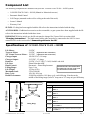
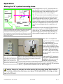
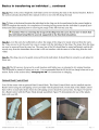
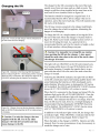
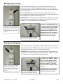
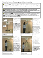
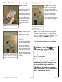
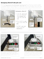
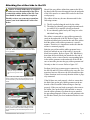
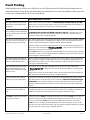
VANDER-TRACK II
600 + 800
FROM VANCARE INC.
Owner’s Manual
Table of Contents
VANDER-TRACK II 600 + 800
Introduction........................................................................................... 3
Overview ................................................................................................ 3
Components of lift system ............................................................... 4
Component List.................................................................................... 5
Specifications....................................................................................... 5
Cautions ................................................................................................. 6
Operation
Turning the lift ON/OFF............................................................... 7
Raising/Lowering the carry bar ............................................... 8
Moving the lift along the track....................................................... 8
Moving the “H” system traversing beam .............................. 9
Basics in transferring an individual ............................................10
Charging the lift .................................................................................12
Emergency Lowering .......................................................................13
Emergency Stopping ........................................................................13
Use of the transcord for emergency raising or lowering .....14
Emergency Shut-Off with Pull Cord …………….………………… 16
Attaching the airline to the lift .....................................................17
Fault finding ........................................................................................19
General inspection and maintenance.........................................20
Lift Accessories.................................................................................21
Service record history .....................................................................22
Warranty ...............................................................................................26
VANDER-TRACK II 600 + 800 - User Guide
Rev: 08/12/2005
Page: 2
CAUTION: DO NOT ATTEMPT TO USE THIS EQUIPMENT
WITHOUT FIRST UNDERSTANDING THE CONTENTS OF
THIS MANUAL.
Introduction
Before using this equipment, and to ensure the safe operation of your VANDER-TRACK II 600 + 800 lift, carefully read this entire manual, especially the section on “Cautions”. The VANDER-TRACK II 600 + 800 is designed to be used in conjunction with Vancare Inc. lift track, accessories and slings. Please refer to any user
guides supplied with these components and refer to them while reviewing this manual.
Should any questions arise from reviewing this manual contact your local authorized Vancare Inc. dealer. Failure to comply with warnings in this manual may result in injury to either the operator, or the individual being
lifted/transferred. Damage to the lift and/or related components may also occur. Be sure that the contents of
this manual are completely understood prior to using this piece of equipment.
Store this manual with the documents included with the lift system and sling (s). Contents of this manual are
subject to change without prior written notice.
Overview of VANDER-TRACK II 600 + 800 lift
The VANDER-TRACK II 600 + 800 is a lifting aid used by health care professionals and those providing care in
the home to lift, position and transfer clients or a disabled family member. The VANDER-TRACK II 600 + 800
lift is part of what is termed ceiling lift technology which takes advantage of lifting from above and not from
below or the side. Additionally the ceiling lift does not take up valuable floor space as most traditional methods do. Finally, the ceiling lift makes it possible to move mobility impaired individuals with minimal strain or
risk to the caregiver, while providing complete safety, dignity and comfort for the client or family member.
The VANDER-TRACK II 600 + 800 lift is one of three major components that make up this technology. The other
two components are the track and sling. The VANDER-TRACK II 600 + 800 lift runs on the lift track which is
securely mounted to the ceiling structure of the institution, or home with the use of ceiling brackets. The track
itself is made of specially designed aluminium and comes in many different shapes, lengths and configurations,
and is custom tailored and installed to meet your specific requirements. The third component, the sling, is a
specially designed fabric accessory that attaches to the lift by means of a carry bar and straps, and holds an individual while the lift, positioning or transfer takes place. Both the track and sling are generally supplied with
the lift at the initial time of purchase. Please refer to any user guides supplied with the VANDER-TRACK II 600
+ 800 lift and reference them while reviewing this manual.
The VANDER-TRACK II 600 + 800 is a fixed ceiling lift, that is, it always remains on the lift track. It has the
ability to lift an individual up from one location such as bed, move the individual along the track to another
location and finally lower the individual into a chair or bath. It is moved along the track in one of two ways.
The first is by manually moving the lift along the track with the aid of a caregiver. The second is by having the
lift power itself along the track. The functions of lifting up or down, or moving to the left or right, are accomplished by pressing buttons of a pneumatically (air) operated hand control. The hand control is attached to the
lift by way of a rubber airline tubing. Due to the design of the lift system, it takes very little effort to press a
button to perform the desired motion.
Please refer to figures 1A and 1B to see sample floor plans of an installed lift system. Refer to figures 2A and
2B to familiarize yourself with the components of the VANDER-TRACK II 600 + 800 lift. Figures 3A and 3B
show the underside view of the lift as it would be seen by an operator.
VANDER-TRACK II 600 + 800 - User Guide
Rev: 08/12/2005
Page: 3
Components of lift system
CHARGER
BATH
BATH
BATHROOM
LIFT
BED
CHARGER
LIFT
TRACK
BATHROOM
BED
TRACK
BEDROOM
BEDROOM
Figure 1A - Sample floor plan showing basic components of
a ceiling lift system.
Figure 1B - Alternate sample floor plan showing basic
components of a ceiling lift system.
transcord
Track
transcord
option
Lifting tape (strap)
Airline tubing
Carry bar
(Optional 3
hook carry bar
shown)
Refer to separate “H” frame manual for
details on the use of this hand control.
Figure 2B - The VANDER-TRACK II 600 + 800
ceiling lift with transcord. The VANDER-TRACK
II 600 + 800 also comes without the transcord.
Pictures in this manual may show both models.
Figure 2A - Basic components of the ceiling lift
Figure 3A—Underside view of the lift
VANDER-TRACK II 600 + 800 - User Guide
Figure 3B - Photo of underside
Rev: 08/12/2005
Page: 4
Component List
The following components are included with your new VANDER-TRACK II 600 + 800 lift system:
• VANDER-TRACK II 600 + 800 lift (Manual or Motorized traverse)
• Pneumatic Hand Control
• Lift Charger (mounted on the wall or ceiling at the end of the track)
• Owner’s Manual
• Warranty Card
SLINGS: If a sling has been supplied with the lift refer to the instructions included with the sling.
ACCESSORIES: If additional accessories such as a turntable, or gate system have been supplied with the lift
refer to the instructions included with those items.
IMPORTANT: Before initial use, the lift unit must be charged for 5 hours. Refer to section titled
"Charging Instructions". The hand control airline tube must also be connected to the lift. If it is not
connected refer to the section titled “Connecting airline to the lift”.
Specifications of VANDER-TRACK II 600 + 800 lift
Lift Motor:
Traverse Motor:
“H” Frame Traverse Motor:
Charger Input:
Charger Output:
Batteries:
Lift Case:
Hand Control:
Lifting Range:
Lift Weight:
Maximum Load:
Duty Cycle:
Rated Performance:
24 VDC
24 VDC (Optional at time of Purchase)
24 VDC (Optional at time of Purchase)
100-240 VAC, 0.9 Amps
29.5 VDC, 1.3 Amps
24 VDC (2 x 12 VDC) 7.0 AH, Sealed Lead Acid
Flame Retardant ABS
Pneumatic – Piston Displacement
Maximum load of the installed lift is
Up to 1.9m
determined by referring to the prod19.5 kg (43 lb)
uct label located on side of lift.
270 kg (600 lb)
10% use, 90% rest
50-80 lifts at 600 lbs, 10% duty cycle, each lift being 24 inches at the
middle of the lifting range (from 54” strap out to 30” strap out) per full battery
22"
74"
563mm
1872mm
96"
2435mm
Models Table for VANDER-TRACK II 600 + 800 Lift
VANDER-TRACK II 600 + 800 - User Guide
Code
Description
8-313117
VANDER-TRACK II 600 + 800 Manual Traverse without
transcord
8-313118
VANDER-TRACK II 600 + 800 Manual Traverse with
transcord
8-313127
VANDER-TRACK II 600 + 800 Power Traverse without
transcord
8-313128
VANDER-TRACK II 600 + 800 Power Traverse with
transcord
8-313137
VANDER-TRACK II 600 + 800 Power Traverse “H” System
without transcord
8-313138
VANDER-TRACK II 600 + 800 Power Traverse “H” System
with transcord
Lifting Range
Rev: 08/12/2005
Page: 5
Cautions
●
The VANDER-TRACK II 600 + 800 must be installed prior to use. Contact your local authorized
dealer to ensure that it is properly installed. The VANDER-TRACK II 600 + 800 must be installed only
by persons authorized by Vancare Inc.
●
Under no circumstance should the VANDER-TRACK II 600 + 800 track, lift and sling (s) or entire sys
tem be put in control of a person who has not been properly trained in the use and care of this
equipment. Failure to adhere to this warning may result in serious injury to the operator, and/or the
individual being lifted/transferred.
●
The VANDER-TRACK II 600 + 800 lift, and associated track and sling (s) are not toys. Do not use it
for unsafe practices. Do not allow children to play with the lift or any of its’ components.
●
The manufacturer's warranty is void if persons unauthorized by Vancare Inc. perform work on
the VANDER-TRACK II 600 + 800 lift system.
●
There are no user serviceable parts inside the cover. Do not remove cover screws, or open the lift
unit, as this will VOID THE WARRANTY.
●
In facilities where more than one operator will be responsible for using the VANDER-TRACK II 600 +
800 lift and associated track and sling (s) it is imperative that all such members be trained in its’
proper use. A training program should be established by the facility to acquaint new operators with
this equipment.
●
Never expose the VANDER-TRACK II 600 + 800 lift directly to water. Warranty does not cover any
misuse or abuse of the lift system.
●
To maintain optimum function, the VANDER-TRACK II 600 + 800 should be inspected and
maintained on a regular basis. See the section titled “General Inspection and Maintenance”.
●
Any accessories used with the VANDER-TRACK II 600 + 800 including track and sling (s), should be
checked to ensure that they are in good working order. Check for signs of wear or fraying prior to use.
Report any unusual wear, or damage immediately to your local authorized Vancare Inc. dealer.
●
The VANDER-TRACK II 600 + 800 lift and associated lift, track and sling (s) are intended only for
lifting and transferring of a person. Vancare Inc. will not be responsible for any damage caused by the
misuse, neglect or purposeful destruction of the lift, and/or its’ associated components.
●
Do not in any circumstance exceed the maximum allowable load of this lift. Refer to the
“Specifications” section of this manual, and/or the labels on the side of the lift.
●
The installation of the lift, track, accessories, and sling are certified to a maximum load. Do not
exceed the maximum rated load of any of the components,
●
There is a risk of explosion if the lift is used in the precsense of flammable anaesthetics.
●
Ensure that a clear space is maintained around the lift and track. Move all curtain material and other
obstacles out of the way before performing a transfer.
VANDER-TRACK II 600 + 800 - User Guide
Rev: 08/12/2005
Page: 6
Operation
Caution: Always, before using the VANDER-TRACK II 600 + 800 lift system, the lift,
track and sling (s) must be visually checked for any unusual wear, or damage. Refer
to the user manual with each piece of supplied equipment to determine what should be
checked. Should anything look unusual contact your local Vancare Inc. dealer prior to
use.
Failure to comply with this caution could result in serious injury to the operator, the individual being lifted and/or damage to the lift.
Turning the lift ON/OFF
Refer to figures 4A, 4B and 4C to determine the hand control that is attached to the lift.
ON/OFF
ON/OFF
Pressing one
of these
buttons will
also turn the
lift on.
Pressing
one of these
buttons will
also turn
the lift on.
Figure 4A - Manual traverse hand
control
Figure 4B - Power traverse hand
control
ON/OFF
Pressing
one of these
buttons will
also turn
the lift on.
Figure 4C - Motorized traverse “H”
system hand control
Figure 4D - Lift ON indicator
VANDER-TRACK II 600 + 800 - User Guide
To operate the lift it must first be turned ON with the
use of the hand control. This can be done in several
ways. The first method is to press the WHITE ON/OFF
button. When this is done the ON/OFF indicator light
located on the underside control panel of the lift will
turn GREEN indicating that the lift is ON. Refer to figures 4D. When the ON/OFF button is pressed again the
lift will turn OFF, and the green indicator light on the
underside of the lift will go out. Refer to figure 4E. If
the lift fails to turn ON at anytime, ensure that the
EMERGENCY OFF switch is not engaged, see page 14
for details.
To conserve battery power the lift will automatically shut
off after approximately 10 minutes on non-use. However,
it is recommended that the lift be turned off when not in
use.
If the batteries of the lift are low and require charging, the
indicator light located on the underside of the lift will turn
ORANGE, and a slow beeping audible alarm will sound.
If the batteries of the lift are completely discharged and
require charging, the indicator light located on the underside of the lift will turn RED, and a fast beeping audible
alarm will sound. When the battery is discharged the UP
function will be disabled. The DOWN and EMERGENCY
DOWN function along with X-Y TRAVERSING will continue to operate. See figure 4F.
Figure 4E - Lift OFF indicator
Rev: 08/12/2005
Figure 4F - Low battery indicator
Page: 7
Operation
Moving the “H” system traversing beam
If the installed track is an “H” system then this section should be reviewed as it describes how to move
the traversing beam. If the installed track is not an
“H” system then this section can be skipped.
TRAVERSING
BEAM
BATH
BED
BATHROOM
The “H” system involves the installation of two parallel support tracks and one traversing beam that is
mounted perpendicular to the two support tracks.
Refer to figure 7A. The benefit of this type of system
is that it provides greater movement and positioning
ability for an individual since the floor space coverage area is much higher than for a single piece of
track.
LIFT
SUPPORT
CHARGING
TRACK
LOCATION
(BOTH SIDES)
BEDROOM
CHARGER
Figure 7A - Sample of “H” system room covering layout. Note that the
lift can be moved along the traversing beam, and that the traversing
beam itself can be moved along the two parallel support tracks.
The actual direction of travel when the hand control buttons are pressed
may be different than shown, since the track and lift orientation may be
different than installed. .
Besides the previously described UP/DOWN movement of the carry bar, and LEFT/RIGHT movement
of the lift, the “H” system adds the ability to move
the traversing beam anywhere along the length of
the two parallel support tracks. Refer to figure 7A.
This can be accomplished in
one of two ways. If the installed
“H” traversing beam is
manually traversing then the
beam is moved along the support tracks by manually moving
the beam, lift, and individual in
one motion. This movement is
the same as that used for a manual traversing lift, as previously
described.
Figure 7B - Power traverse “H”
system hand control showing traversing beam movement buttons.
Button colors correspond to the
black and white directional arrows
located on the underside of the lift.
If the installed “H” system traversing beam is motorized traversing then the beam is moved
along the support tracks by
pressing either the black or white hand control button. Refer to figure 7B. This
will move the beam in the direction of travel as noted by the black [▼] and white
arrows [▲]located on the underside of the lift. Refer to figure 7C.
Figure 7C - Directional arrows on underside of power traverse
“H” system lift. Black and white arrows show traversing beam
direction of travel when the corresponding colored button is
pressed on the hand control.
Caution: Always use extreme care when moving the traversing beam. Watch out for
and avoid any obstructions that may cause injury to the individual in the sling, or damage to the lift/track.
VANDER-TRACK II 600 + 800 - User Guide
Rev: 08/12/2005
Page: 9
Basics in transferring an individual
Caution: The following steps are intended to generally illustrate the procedure involved in the lifting
and transferring of an individual from one location to another using the lift, track and sling. Track configurations will vary by installation.
The manual for the sling that was purchased with the lift should be reviewed in detail prior to attempting these steps, as the sling illustrated here may not be the same as the one that was purchased.
Contact your local authorized Vancare Inc. dealer if you have any questions or concerns.
Step 1) Move the lift away from the charging station or current location and close to the individual that is to be
transferred. Use the procedures for up and down and moving along the track as described in the sections titled,
“Raising/lowering the lift” and “Moving the lift along the track”.
Caution: Always use extreme care when moving the lift along the track. Watch out for and
avoid any obstructions that may cause injury to the individual in the sling, or damage to the
lift/track.
Step 2) Prepare the individual being transferred with the appropriate sling. Refer to the instructions supplied
with the sling that was purchased on how to properly outfit an individual with a sling.
Caution: Always make sure that the sling is correctly fitted and adjusted on each side of the
individual so that maximum comfort and safety are achieved prior to lifting.
Step 3) Once the individual has been outfitted with the sling, move the lift so that it is positioned directly over
the individual. Lower the carry bar to a height so that the straps of the sling can be easily attached to the carry
bar.
Caution: Always check to ensure that the lift is correctly positioned directly above the person to be lifted. Over time, the lift strap may fray if this is not followed.
Caution: Check to ensure that the carry bar has no cuts, dents or sharp edges that may
come in contact with the straps of the sling and cause damage to them. Report any concerns to
your local authorized dealer.
Step 4) Attach the straps of the sling to the hooks of the carry bar. The straps on each side of the sling are generally attached to the corresponding side of the carry bar. Be sure to double check to ensure that the straps are
properly attached to the carry bar, and that the individual being lifted is properly positioned in the sling prior to
lifting.
Caution: Prior to lifting an individual make sure that the straps of the sling are securely
placed on the hooks of the carry bar.
Step 5) The individual may now be raised with the use of the UP button on the hand control. While lifting is
in progress the height required in order for the transfer to be completed safely should be closely observed. Ensure that the individual being lifted will not be injured by any obstructions during the initial lifting.
Caution: Always use caution when lowering/raising an individual who is in the sling of the
lift. Watch out for and avoid any obstructions that may cause injury to the individual, or damage to the lift.
VANDER-TRACK II 600 + 800 - User Guide
Rev: 08/12/2005
Page: 10
Emergency Lowering
In the event that the DOWN arrow button on the hand control does not
function, the alternate DOWN button can be used to lower an individual.
This is achieved by pressing the WHITE DOWN arrow on the hand control.
Refer to figure 10A.
Should both DOWN arrow buttons fail, the person may be lowered by
pressing the RED emergency lowering button located on the control panel on
the underside of the lift unit. Refer to figure 10B.
IMPORTANT: The Emergency Lowering button does not provide a raising
function. The failure of any of the lowering devices should be reported to
Vancare Inc. or your authorized dealer immediately.
Caution: The RED button can
be operated using a broom handle
or walking stick to press the button upward. This eliminates the
need to mount a ladder or stool.
Figure 10A - Power traverse hand
control showing alternate DOWN
button for lift. For other lift hand
controls this button is in the same
position.
Should you have any concerns or
questions contact your local authorized Vancare Inc. dealer.
Figure 10B –RED emergency lowering
button located on underside of lift case.
Emergency Stopping
The emergency stop is operated by pressing the WHITE ON/OFF button on
the hand control or the GREEN button on the control panel on the underside
of the lift unit. Refer to figures 11A and 11B respectively.
IMPORTANT: The Emergency Lowering button does not provide a raising function. The failure of any of the lowering devices should be reported
to Vancare Inc. or your authorized dealer immediately.
Figure 11A - Power traverse hand
control showing emergency stop
button for lift. For other lift hand
controls this button is in the same
position.
VANDER-TRACK II 600 + 800 - User Guide
Caution: The GREEN button
can be operated using a broom
handle or walking stick to press
the button upward. This eliminates the need to mount a ladder
or stool.
Figure 11B - GREEN emergency stop
button located on underside of lift case.
Rev: 08/12/2005
Should you have any concerns or
questions contact your local authorized Vancare Inc. dealer.
Page: 13
Use of the transcord for emergency raising or lowering
Caution: The transcord manual emergency raising and lowering system should be used only if the
lowering procedures described in the previous section of the manual do not work, or, if the emergency
raising function is required. Should you have any concerns or questions contact your local authorized
Vancare Inc. dealer.
Caution: A proper safety ladder or stool may be required in order to remove the cover of the
transcord emergency lowering/raising device. Use extreme caution if this is required. Should you have
any concerns or questions contact your local authorized Vancare Inc. dealer.
Caution: Once the transcord has been removed from the cover of the lift, the hand control buttons
for UP/DOWN will not function. This is a built in safety feature. DO NOT use the lift after the
transcord mechanism has been used. The transcord must be reset by a qualified lift technician after use.
contact your local authorized Vancare Inc. dealer.
transcord
cover
transcord
handle
Step 1) Visually locate the transcord
located on the side of
the lift. Determine if
the transcord handle can be reached
by raising your hand
or if an small safety
ladder or stool is required in order to
access it. Refer to
figure 12A.
Figure 12B– Grab the handle of the
transcord and pull downward to disconnect it from the cover of the lift.
Figure 12A- Lift showing location of
the transcord.
Step 3) Gently lower
the transcord downward. As this is being
completed a chain
will come out from
the top of the cover
of the transcord.
Refer to figure 12C.
Figure 12C - Lower the transcord. A
chain located inside the cover will
come out as this is being completed.
VANDER-TRACK II 600 + 800 - User Guide
When the transcord
has been lowered to a
comfortable height
descend from the ladder or stool to the
floor. Use caution
when doing this.
Step 2) With one of
your hands grab the
handle of the
transcord and gently
pull downwards so that
the cover of the
transcord is disconnected from the side of
the lift. Refer to figure
12B. Use caution when
a ladder or stool be
required to reach the
lift. Ensure that the
ladder or stool is properly secured before
proceeding.
Step 4) Continue to
lower the transcord
downward until it has
reached its’ lowest
point. The chain is
now completely
removed from the
cover. Refer to figure
12D.
If a ladder or stool has
been used to access
the transcord move
it away from the immediate area.
Figure 12D - Lower the transcord
such that the chain inside the cover is
completely removed.
Rev: 08/12/2005
Page: 14
Use of the transcord for emergency raising or lowering...con’t
Step 6) Once the instructions have been read and
understood, grab hold of
the specific chain that will
either lower or raise the
carry bar of the lift. In a
repetitive motion keep
pulling the chain down.
The carry bar will begin to
move in the desired direction. Refer to figure 12F.
Step 5) Turn the
transcord cover over
and find the instructions
located on the back.
Carefully read these instruction. They will direct you to pull one of
the chains downward
that will move the carry
bar upward or downward. Refer to figure
12E.
Figure 12E - Turn the cover of the
transcord over and carefully read
the instructions on the back.
Figure 12F - Grab the chain
that will either raise or lower
the carry bar and pull it in a
downward motion.
Step 7) Continue to pull
the desired chain downward to raise or lower
the carry bar to the desired height. Refer to
figure 12G.
Figure 12G - Continue to pull the
chain downward until the desired
height is achieved. This may take
several minutes depending on the
speed at which the chain is pulled.
Once the desired height
is achieved then the individual in the sling of the
lift can be positioned
safely in the desired position. Before the straps
of the sling are removed
from the carry bar ensure
that the individual in the
sling has been positioned
securely.
Step 8) Once the transfer has been completed,
the lift must be serviced by an authorized Vancare Inc. dealer before it can be used again. This
involves resetting the transcord and remounting it onto the side of the lift.
Contact your local authorized dealer immediately after the transfer has been completed.
Caution: Once the transcord
has been used and the transfer
completed DO NOT use the lift.
Contact your local authorized Vancare Inc. dealer to have the
transcord reset.
Failure to adhere to this warning
may result in damage to the lift
and/or injury to the caregiver and/
or individual being transferred.
Should you have any concerns or
questions contact your local authorized Vancare Inc. dealer.
VANDER-TRACK II 600 + 800 - User Guide
Rev: 08/12/2005
Page: 15
Attaching the airline tube to the lift
Caution: A sturdy ladder may be required
in order to access the underside of the lift to
re-attach the rubber airline of the lift. Caution should be used when this is required.
Should the gray rubber airline that connects the lift to
the hand control become disengaged from the underside
of the lift it must be re-connected in order for the lift to
work properly.
Should you have any concerns or questions
contact your local authorized Vancare Inc.
dealer.
The rubber airline may become disconnected for the
following reasons:
1) The lift is pulled along the track by the airline.
2) The tubing accidentally gets wrapped around an object while a lift or transfer is being performed.
3) It is accidentally pulled out by the caregiver or the
individual being lifted.
The airline is connected to a gray rubber grommet located on the underside of the lift. Refer to figure 13A.
Small metal ribbed pins located at the end of the airline
hold the airline to this rubber grommet is a specific
manner. Therefore it is important to make sure that the
airline is connected properly.
Figure 13A - Gray rubber grommet located on underside of lift. Rubber airline is not connected. Note black
line on grommet.
Metal pins that get inserted into
the holes of the grommet of the
lift.
Figure 13B - Gray rubber airline being inserted into
rubber grommet of lift. The black markings on both
pieces are lined up. The metal ribbed pins are on the
airline.
Pieces connected together
Both the gray airline and the rubber grommet have a
black line marked on one of their sides. Line up the
black lines together. Refer to figure 13B. When this is
done then the metal ribbed pins attached to the end of
the airline can be re-insert into the corresponding holes
in the rubber grommet on the underside of the lift. Be
sure to insert the pins into the gray rubber grommet sufficiently so that it is secure. Refer to figure 13C.
Perform a brief test to ensure proper connectivity. Turn
the lift ON and OFF. Raise and lower the carry bar. For
motorized traverse lifts move the lift left and then right.
If these functions work correctly then the airline is properly connected.
If the lift does not work properly, check to ensure that
the black lines on the gray rubber grommet on the underside of the lift and the airline tubing are lined up
properly. If they are not lined up properly, then remove
the airline, line up the black lines and then re-insert it
into the rubber grommet. Perform the test as noted in
the preceding paragraph. If there are still problems with
the lift then contact your local authorized dealer for service.
Figure 13C - Gray rubber airline being inserted into
rubber grommet of lift. The black markings on both
pieces are lined up. The metal ribbed pins are on the
airline.
VANDER-TRACK II 600 + 800 - User Guide
Rev: 08/12/2005
Page: 17
This page left
intentionally blank
VANDER-TRACK II 600 + 800 - User Guide
Rev: 08/12/2005
Page: 18
Fault Finding
Should problems arise with the use of the lift review the following chart. Find the fault and complete the recommended solution. If the fault is not found and/or the solution does not correct the problem contact your local
Vancare Inc. authorized dealer for service immediately.
Fault
Recommended Solution
The airline tubing that connects the
hand control to the lift has become
disengaged.
Refer to the section of this manual titled “Attaching the airline tube to the lift”.
If this does not correct the problem then contact your local authorized dealer immediately so
that the lift can be checked to ensure proper continued operation.
The hand control buttons do not operate according to their designations
(e.g. the UP button initiates a traverse
movement).
The airline tubing has not been connected correctly. Refer to the section of this manual titled
“Attaching the airline and hand control to the lift”. If this does not correct
the problem then contact your local authorized dealer immediately so that the lift can be
checked to ensure proper continued operation.
The carry bar of the lift does not operate up or down even when the airline has been properly connected.
The indicator light on the control panel located on the underside of the lift should be GREEN.
Press the ON/OFF button or UP/DOWN arrow buttons or any coloured button on the hand
control. This should activate the lift and the indicator light turn GREEN.
If the lift still does not function, then the batteries may be low and require charging. Refer to
the section of this manual titled “Charging the lift”. Charge the lift for at least one hour
and then try to raise/lower the carry bar.
If the transcord has been used then the UP and DOWN functions will not operate. DO NOT
use the lift. Contact your local authorized dealer immediately so that the lift can be checked
to ensure proper continued operation.
The GREEN light on the underside
of the lift is ON and the lift does not
operate in the DOWN direction.
There is a built-in slack tape detector in the lift. This may be sensitive. Apply weight to the
carry bar while pressing the DOWN button. If this corrects the problem temporarily but not
permanently then contact your local authorized dealer so that the lift can be checked to ensure proper continued operation.
The red indicator light on the underside lift turns RED and/or a loud
alarm sound is heard when an individual is raised.
The batteries are low and require charging. Refer to the section of this manual titled
“Charging the lift”. Charge the lift for at least one hour and then try to raise/lower the
carry bar.
One side of the lift tape (strap) is
starting to fray after continued use.
Check to be sure that the lift is always directly above the individual being lifted, especially
with motorized traversing lifts. Refer to the section titled “Basics in transferring an
individual” for correct lift positioning. If fraying still continues then contact your local
authorized dealer immediately so that the lift can be checked to ensure proper continued operation.
If this does not correct the problem then contact your local authorized dealer immediately so
that the lift can be checked to ensure proper continued operation.
The lift does not pass through a track Refer to the “Owners Manual” for the specific piece of equipment in question. If the recomcomponent such as a turntable or
mended solution does not correct the problem then contact your local authorized dealer imgate.
mediately so that the lift can be checked to ensure proper continued operation.
The transcord chain will not lower
the carry bar of the lift.
Check to ensure the transcord chain has been fully let out from the transcord cover. If it
has not been fully let out then complete this task and then proceed to lower the carry bar.
Check to ensure that the transcord chain is not tangled, especially where it enters the
transcord cover. Untangle the chain and then proceed with lowering the carry bar. If this
does not correct the problem then contact your local authorized dealer immediately so that the
lift can be checked to ensure proper continued operation.
VANDER-TRACK II 600 + 800 - User Guide
Rev: 08/12/2005
Page: 19
General Inspection and Maintenance
A) Each Use - To be completed by User
Prior to each use the VANDER-TRACK II 600 + 800 lift and associated track, accessories and sling (s), must be
visually inspected. Refer to the accessory and sling user guides for specific details regarding their inspection.
Should any of the these items fail the inspection do not use the lift
Contact your local authorized dealer for service.
Visually check for the following:
The lift lifting tape shows NO signs of fraying or breaking along its entire length.
□
□
The stitching on the lift lifting tape where it connects to the carry bar shows NO signs of fraying, or
□
□
□
□
□
□
□
breaking.
The sling (s) that will be used shows NO signs of unusual wear and tear. The straps of the sling that connect
to the carry bar of the lift show NO signs of fraying or breaking. Refer to specific sling instructions.
The airline tube that connects the hand control to the lift is not kinked, twisted, knotted, cut or damaged.
All the functions on the hand control work correctly (e.g. UP/DOWN/.LEFT/RIGHT, etc..).
The brackets that hold the track in place on the ceiling are secure and do not move or appear loose.
There are not cuts, dents or sharp edges on the carry bar that may damage the straps of the sling.
The lift has no unusual sounds when the carry bar is moved UP/DOWN or the lift is moved
LEFT/RIGHT.
Ensure that there are end stops installed at each end of the track.
B) Monthly - To be completed by User
Should any of the these items fail the inspection do not use the lift.
Contact your local authorized dealer for service.
□
Complete the visual inspection as noted in the “Each Use” section above.
With no one in the sling nor attached to the lift check the following:
□
The lift moves freely along the entire length of the track.
C) Semi-Annual or Yearly - To be completed by a lift technician
Consult your local authorized dealer for advice on whether this section should be completed every 6
months or on a yearly basis. Generally, in frequent use, or in situations where heavier than normal
clients are lifted, or in multi-user environments such as in institutions the lift should be checked every 6
months
This section to be only completed by a qualified service technician as authorized by Vancare
Inc.
□
Complete the visual inspection as noted in the “Monthly” section above.
Complete the preventative maintenance procedure as outlined in technical manuals for the
VANDER-TRACK II 600 + 800 system.
□
VANDER-TRACK II 600 + 800 lift checked and passed. Any required repairs completed.
VANDER-TRACK II 600 + 800 - User Guide
Rev: 08/12/2005
Page: 20
Lift Accessories
The following is a list of available accessories for the VANDER-TRACK II 600 + 800 lift. Items such as the
track, turntables and brackets are installed at the time of purchase. Add-on pieces are available to after the initial purchase, however your local authorized dealer must be consulted as to suitability, purchase and installation.
Slings are the most common after purchase accessory. A variety of styles, sizes, and colors are available. Custom slings can also be manufactured to meet special needs. Consult your local authorized dealer for details,
pricing and a complete list of current sling models.
TRACK
1.82MTR (6FT) AND
2.5MTR (8FT) LENGTHS.
MAY BE CUT AT TIME
OF INSTALLATION
TRACK
45 DEGREE CURVE
MAY BE CUT AT TIME
OF INSTALLATION
TRACKPLUS TRACK
5.0MTR (16FT) AND
6.0MTR (19.5FT) LENGTHS.
MAY BE CUT AT TIME
OF INSTALLATION
TRACK
5.0MTR (16FT) LENGTH
MAY BE CUT AT TIME
OF INSTALLATION
TRACK
TRANSGATE SYSTEM
90 DEGREE CURVE
MAY BE CUT AT TIME
OF INSTALLATION
TRACK END STOP
"H" SYSTEM TROLLEY SET
USED ONLY WITH "H" FRAME
AREA COVERING SYSTEM
(MANUAL OR MOTORISED)
MULTI-PORT TURNTABLE
SYSTEM
WALL MOUNT
BRACKET
3" TRACK
BRACKET
QUICK FIT TURNTABLE
SYSTEM
6" CONNECTOR
BRACKET
ACCESSORIES NOT TO SCALE.
FOR ILLUSTRATIVE PURPOSES ONLY.
VARIOUS STYLES AND SIZES OF SLINGS.
CUSTOM SLINGS AVAILABLE.
NOTICE: ACCESSORY SIZE, STYLE, SHAPE, LENGTH,
CONFIGURATIONS, OPTIONS, COLORS AND
SPECIFICATIONS
MAY CHANGE WITHOUT PRIOR WRITTEN NOTICE.
CONTACT YOUR LOCAL AUTHORIZED DEALER FOR DETAILS.
CAUTION: ONLY SLINGS AUTHORIZED BY VANCARE INC.
ARE TO BE USED WITH THIS LIFT. CONTACT YOUR LOCAL
AUTHORIZED DEALER FOR DETAILS.
VANDER-TRACK II 600 + 800 - User Guide
Rev: 08/12/2005
Page: 21
Service Record History - Initial Information
•
•
•
•
Complete the following section on Purchase and Service Information as soon as this
equipment is installed.
Use the service record history to record to any completed service and repairs.
Ensure that the service record is signed and dated each time it is used.
Be sure to have this piece of equipment serviced on a regular basis as described in the
General Inspection and Maintenance Section.
PURCHASE INFORMATION:
Product Name: VANDER-TRACK II 600 + 800 lift
Model: ____________________________
Serial#:________________________
Date of Purchase: _____________________
Date Installed: _________________
Purchased From: ___________________________________________________________
(local authorized Vancare Inc. dealer)
Address:
_______________________________________
City:
__________________________
Telephone No:
__________________________
Postal Code: ________________
Comments:
SERVICE INFORMATION:
Contact the following company for service:
Company:
___________________________________________________________
(local authorized Vancare Inc. dealer)
Address:
_______________________________________
City:
__________________________
Telephone No:
__________________________
Postal Code: ________________
Comments:
VANDER-TRACK II 600 + 800 - User Guide
Rev: 08/12/2005
Page: 22
Service Record History
Date: _______________________
Service Type: □ Periodic Inspection
Complete this section after each service, repair inspection and/
or maintenance. Photocopy additional pages as required.
Time: ________________________
□ Monthly Inspection
Completed By: _________________________
□ 6 Month Inspection □ Repair □ Yearly Inspection □ Other:_________
_____________________________
Printed Name
Signature
Company: _____________________________________________________________
Remarks & Action Taken:
Date: _______________________
Service Type: □ Periodic Inspection
Time: ________________________
□ Monthly Inspection
Completed By: _________________________
□ 6 Month Inspection □ Repair □ Yearly Inspection □ Other:_________
_____________________________
Printed Name
Signature
Company: _____________________________________________________________
Remarks & Action Taken:
VANDER-TRACK II 600 + 800 - User Guide
Rev: 08/12/2005
Page: 23
Service Record History
Date: _______________________
Service Type: □ Periodic Inspection
Complete this section after each service, repair inspection and/
or maintenance. Photocopy additional pages as required.
Time: ________________________
□ Monthly Inspection
Completed By: _________________________
□ 6 Month Inspection □ Repair □ Yearly Inspection □ Other:_________
_____________________________
Printed Name
Signature
Company: _____________________________________________________________
Remarks & Action Taken:
Date: _______________________
Service Type: □ Periodic Inspection
Time: ________________________
□ Monthly Inspection
Completed By: _________________________
□ 6 Month Inspection □ Repair □ Yearly Inspection □ Other:_________
_____________________________
Printed Name
Signature
Company: _____________________________________________________________
Remarks & Action Taken:
Date: _______________________
Service Type: □ Periodic Inspection
Time: ________________________
□ Monthly Inspection
Completed By: _________________________
□ 6 Month Inspection □ Repair □ Yearly Inspection □ Other:_________
_____________________________
Printed Name
Signature
Company: _____________________________________________________________
Remarks & Action Taken:
Date: _______________________
Service Type: □ Periodic Inspection
Time: ________________________
□ Monthly Inspection
Completed By: _________________________
□ 6 Month Inspection □ Repair □ Yearly Inspection □ Other:_________
_____________________________
Printed Name
Signature
Company: _____________________________________________________________
Remarks & Action Taken:
Date: _______________________
Service Type: □ Periodic Inspection
Time: ________________________
□ Monthly Inspection
Completed By: _________________________
□ 6 Month Inspection □ Repair □ Yearly Inspection □ Other:_________
_____________________________
Printed Name
Signature
Company: _____________________________________________________________
Remarks & Action Taken:
Date: _______________________
Service Type: □ Periodic Inspection
Time: ________________________
□ Monthly Inspection
Completed By: _________________________
□ 6 Month Inspection □ Repair □ Yearly Inspection □ Other:_________
_____________________________
Printed Name
Signature
Company: _____________________________________________________________
Remarks & Action Taken:
VANDER-TRACK II 600 + 800 - User Guide
Rev: 08/12/2005
Page: 24
Service Record History
Date: _______________________
Service Type: □ Periodic Inspection
Complete this section after each service, repair inspection and/
or maintenance. Photocopy additional pages as required.
Time: ________________________
□ Monthly Inspection
Completed By: _________________________
□ 6 Month Inspection □ Repair □ Yearly Inspection □ Other:_________
_____________________________
Printed Name
Signature
Company: _____________________________________________________________
Remarks & Action Taken:
Date: _______________________
Service Type: □ Periodic Inspection
Time: ________________________
□ Monthly Inspection
Completed By: _________________________
□ 6 Month Inspection □ Repair □ Yearly Inspection □ Other:_________
_____________________________
Printed Name
Signature
Company: _____________________________________________________________
Remarks & Action Taken:
Date: _______________________
Service Type: □ Periodic Inspection
Time: ________________________
□ Monthly Inspection
Completed By: _________________________
□ 6 Month Inspection □ Repair □ Yearly Inspection □ Other:_________
_____________________________
Printed Name
Signature
Company: _____________________________________________________________
Remarks & Action Taken:
Date: _______________________
Service Type: □ Periodic Inspection
Time: ________________________
□ Monthly Inspection
Completed By: _________________________
□ 6 Month Inspection □ Repair □ Yearly Inspection □ Other:_________
_____________________________
Printed Name
Signature
Company: _____________________________________________________________
Remarks & Action Taken:
Date: _______________________
Service Type: □ Periodic Inspection
Time: ________________________
□ Monthly Inspection
Completed By: _________________________
□ 6 Month Inspection □ Repair □ Yearly Inspection □ Other:_________
_____________________________
Printed Name
Signature
Company: _____________________________________________________________
Remarks & Action Taken:
Date: _______________________
Service Type: □ Periodic Inspection
Time: ________________________
□ Monthly Inspection
Completed By: _________________________
□ 6 Month Inspection □ Repair □ Yearly Inspection □ Other:_________
_____________________________
Printed Name
Signature
Company: _____________________________________________________________
Remarks & Action Taken:
VANDER-TRACK II 600 + 800 - User Guide
Rev: 08/12/2005
Page: 25
Warranty
This Warranty does not affect or in any way limit your Statutory Rights
1) Subject to the exclusions set out in Clause 2, the conditions set out in Clause 3 and the limitations set out in
Clause 4, Vancare Inc., as sole licensed representative of Corven Healthcare Inc., guarantees all equipment
supplied as new against failure within the period of 2 years from date of purchase by virtue of defects in
material or workmanship.
2) This guarantee does not apply to failure attributable to normal wear and tear, damage by natural forces,
user neglect or misuse or to deliberate destruction, or to batteries more than 90 days after original purchase.
3) This guarantee shall be void if the equipment is not serviced by Vancare Inc. or its authorized service
agents in accordance with the manufacturer’s recommendations or if any unauthorized person carries out
works on the equipment.
4) The liability of Vancare Inc. under the terms of this guarantee shall be limited to the replacement of
defective parts and in no event shall Vancare Inc. incur liability for any consequential or unforeseeable
losses.
VANDER-TRACK II 600 + 800 - User Guide
Rev: 08/12/2005
Page: 26