1
Introduction
Thank you for selecting the Mitsubishi numerical control unit. This instruction manual describes the handling and
caution points for using this AC servo/spindle.Incorrect handling may lead to unforeseen accidents, so always read
this instruction manual thoroughly to ensure correct usage.
Make sure that this instruction manual is delivered to the end user. Always store this manual in a safe place.
In order to confirm if all function specifications described in this manual are applicable, refer to the specifications for
each CNC.
Notes on Reading This Manual
(1) Since the description of this specification manual deals with NC in general, for the specifications of individual
machine tools, refer to the manuals issued by the respective machine manufacturers. The "restrictions" and
"available functions" described in the manuals issued by the machine manufacturers have precedence to
those in this manual.
(2) This manual describes as many special operations as possible, but it should be kept in mind that items not
mentioned in this manual cannot be performed.
Precautions for Safety
Please read this manual and auxiliary documents before starting installation, operation, maintenance or inspection
to ensure correct usage. Thoroughly understand the device, safety information and precautions before starting
operation.
The safety precautions in this instruction manual are ranked as "WARNING" and "CAUTION".
DANGER
When there is a potential risk of fatal or serious injuries if handling is mistaken.
WARNING
When a dangerous situation, or fatal or serious injuries may occur if handling is mistaken.
CAUTION
When a dangerous situation may occur if handling is mistaken leading to medium or minor injuries, or physical
damage.
Note that some items described as "
CAUTION" may lead to major results depending on the situation. In any
case, important information that must be observed is described.
The signs indicating prohibited and mandatory matters are explained below.
Indicates a prohibited matter. For example, "Fire Prohibited" is indicated as
Indicates a mandatory matter. For example, grounding is indicated as
.
.
The meaning of each pictorial sign is as follows.
CAUTION
CAUTION rotated
object
CAUTION HOT
Danger Electric shock
risk
Danger explosive
Prohibited
Disassembly is
prohibited
KEEP FIRE AWAY
General instruction
Earth ground
After reading this specifications and instructions manual, store it where the user can access it easily for reference.
The numeric control unit is configured of the control unit, operation board, servo drive unit, spindle drive unit, power
supply, servo motor and spindle motor, etc.
In this section "Precautions for safety", the following items are generically called the "motor".
• Servo motor
• Linear servo motor
• Spindle motor
• Direct-drive motor
In this section "Precautions for safety", the following items are generically called the "unit".
• Servo drive unit
• Spindle drive unit
• Power supply unit
• Scale interface unit
• Magnetic pole detection unit
POINT
Important matters that should be understood for operation of this machine are indicated as a POINT in this
manual.
For Safe Use
Mitsubishi CNC is designed and manufactured solely for applications to machine tools to be used for industrial
purposes.
Do not use this product in any applications other than those specified above, especially those which are
substantially influential on the public interest or which are expected to have significant influence on human lives or
properties.
WARNING
1. Electric shock prevention
Do not open the front cover while the power is ON or during operation. Failure to observe this could lead to
electric shocks.
Do not operate the unit with the front cover removed. The high voltage terminals and charged sections will
be exposed, and can cause electric shocks.
Do not remove the front cover and connector even when the power is OFF unless carrying out wiring work
or periodic inspections. The inside of the units is charged, and can cause electric shocks.
Since the high voltage is supplied to the main circuit connector while the power is ON or during operation,
do not touch the main circuit connector with an adjustment screwdriver or the pen tip. Failure to observe
this could lead to electric shocks.
Wait at least 15 minutes after turning the power OFF, confirm that the CHARGE lamp has gone out, and
check the voltage between P and N terminals with a tester, etc., before starting wiring, maintenance or
inspections. Failure to observe this could lead to electric shocks.
Ground the unit and motor. For the motor, ground it via the drive unit.
Wiring, maintenance and inspection work must be done by a qualified technician.
Wire the servo drive unit and servo motor after installation. Failure to observe this could lead to electric
shocks.
Do not touch the switches with wet hands. Failure to observe this could lead to electric shocks.
Do not damage, apply forcible stress, place heavy items on the cables or get them caught. Failure to
observe this could lead to electric shocks.
After assembling the built-in IPM spindle motor, if the rotor is rotated by hand etc., voltage occurs between
the terminals of lead. Take care not to get electric shocks.
WARNING
2. Injury prevention
When handling a motor, perform operations in safe clothing.
In the system where the optical communication with CNC is executed, do not see directly the light
generated from CN1A/CN1B connector of drive unit or the end of cable. When the light gets into eye, you
may feel something is wrong for eye.
(The light source of optical communication corresponds to class1 defined in JISC6802 or IEC60825-1.)
The linear servo motor, direct-drive motor and built-in IPM spindle motor uses permanent magnets in the
rotor, so observe the following precautions.
(1)Handling
• The linear servo motor, direct-drive motor and built-in IPM spindle motor could adversely affect medical
electronics such as pacemakers, etc., therefore, do not approach the rotor.
• Do not place magnetic materials as iron.
• When a magnetic material as iron is placed, take safety measure not to pinch fingers or hands due to the
magnetic attraction force.
• Remove metal items such as watch, piercing jewelry, necklace, etc.
• Do not place portable items that could malfunction or fail due to the influence of the magnetic force.
• When the rotor is not securely fixed to the machine or device, do not leave it unattended but store it in the
package properly.
(2)Transportation and storage
• Correctly store the rotor in the package to transport and store.
• During transportation and storage, draw people's attention by applying a notice saying "Strong magnetHandle with care" to the package or storage shelf.
• Do not use a damaged package.
(3)Installation
• Take special care not to pinch fingers, etc., when installing (and unpacking) the linear servo motor.
CAUTION
1. Fire prevention
Install the units, motors and regenerative resistor on non-combustible material. Direct installation on
combustible material or near combustible materials could lead to fires.
Always install a circuit protector and contactor on the servo drive unit power input as explained in this
manual. Refer to this manual and select the correct circuit protector and contactor. An incorrect selection
could result in fire.
Shut off the power on the unit side if a fault occurs in the units. Fires could be caused if a large current
continues to flow.
When using a regenerative resistor, provide a sequence that shuts off the power with the regenerative
resistor's error signal. The regenerative resistor could abnormally overheat and cause a fire due to a fault
in the regenerative transistor, etc.
The battery unit could heat up, ignite or rupture if submerged in water, or if the poles are incorrectly wired.
Cut off the main circuit power with the contactor when an alarm or emergency stop occurs.
2. Injury prevention
Do not apply a voltage other than that specified in this manual, on each terminal. Failure to observe this
item could lead to ruptures or damage, etc.
Do not mistake the terminal connections. Failure to observe this item could lead to ruptures or damage,
etc.
Do not mistake the polarity (+,- ). Failure to observe this item could lead to ruptures or damage, etc.
Do not touch the radiation fin on unit back face, regenerative resistor or motor, etc., or place parts (cables,
etc.) while the power is turned ON or immediately after turning the power OFF. These parts may reach high
temperatures, and can cause burns or part damage.
Structure the cooling fan on the unit back face, etc., etc so that it cannot be touched after installation.
Touching the cooling fan during operation could lead to injuries.
Take care not to suck hair, clothes, etc. into the cooling fan.
CAUTION
3. Various precautions
Observe the following precautions. Incorrect handling of the unit could lead to faults, injuries and electric shocks, etc.
(1) Transportation and installation
Correctly transport the product according to its weight.
Use the motor's hanging bolts only when transporting the motor. Do not transport the machine when the
motor is installed on the machine.
Do not stack the products above the tolerable number.
Follow this manual and install the unit or motor in a place where the weight can be borne.
Do not get on top of or place heavy objects on the unit.
Do not hold the cables, axis or encoder when transporting the motor.
Do not hold the connected wires or cables when transporting the units.
Do not hold the front cover when transporting the unit. The unit could drop.
Always observe the installation directions of the units or motors.
Secure the specified distance between the units and control panel, or between the servo drive unit and
other devices.
Do not install or run a unit or motor that is damaged or missing parts.
Do not block the intake or exhaust ports of the motor provided with a cooling fan.
Do not let foreign objects enter the units or motors. In particular, if conductive objects such as screws or
metal chips, etc., or combustible materials such as oil enter, rupture or breakage could occur.
Provide adequate protection using a material such as connector for conduit to prevent screws, metallic
detritus, water and other conductive matter or oil and other combustible matter from entering the motor
through the power line lead-out port.
The units, motors and encoders are precision devices, so do not drop them or apply strong impacts to
them.
CAUTION
Store and use the units under the following environment conditions.
Environment
Ambient temperature
Ambient humidity
Atmosphere
Altitude
Unit
Operation: 0 to 55°C (with no freezing),
Storage / Transportation: -15°C to 70°C
(with no freezing)
Motor
Operation: 0 to 40°C (with no freezing),
Storage: -15°C to 70°C (Note2) (with no freezing)
Operation: 90%RH or less
(with no dew condensation)
Storage / Transportation: 90%RH or less
(with no dew condensation)
Operation: 80%RH or less
(with no dew condensation),
Storage: 90%RH or less
(with no dew condensation)
Indoors (no direct sunlight)
With no corrosive gas, inflammable gas, oil mist, dust or conductive fine particles
Operation/Storage:
1000 meters or less above sea level,
Transportation:
13000 meters or less above sea level
Vibration/impact
Operation:
1000 meters or less above sea level,
Storage:
10000 meters or less above sea level
According to each unit or motor specification
(Note 1) For details, confirm each unit or motor specifications in addition.
(Note 2) -15°C to 55°C for linear servo motor.
When disinfectants or insecticides must be used to treat wood packaging materials, always use methods
other than fumigation (for example, apply heat treatment at the minimum wood core temperature of 56 °C
for a minimum duration of 30 minutes (ISPM No. 15 (2009))).
If products such as units are directly fumigated or packed with fumigated wooden materials, halogen
substances (including fluorine, chlorine, bromine and iodine) contained in fumes may contribute to the
erosion of the capacitors.
When exporting the products, make sure to comply with the laws and regulations of each country.
Do not use the products in conjunction with any components that contain halogenated flame retardants
(bromine, etc). Failure to observe this may cause the erosion of the capacitors.
Securely fix the servo motor to the machine. Insufficient fixing could lead to the servo motor slipping off
during operation.
Always install the servo motor with reduction gear in the designated direction. Failure to do so could lead
to oil leaks.
Structure the rotary sections of the motor so that it can never be touched during operation. Install a cover,
etc., on the shaft.
When installing a coupling to a servo motor shaft end, do not apply an impact by hammering, etc. The
encoder could be damaged.
Do not apply a load exceeding the tolerable load onto the servo motor shaft. The shaft could break.
Store the motor in the package box.
When inserting the shaft into the built-in IPM spindle motor, do not heat the rotor higher than 130°C. The
magnet could be demagnetized, and the specifications characteristics will not be ensured.
Always use a nonmagnetic tool (explosion-proof beryllium copper alloy safety tool: NGK Insulators, etc.)
when installing the built-in IPM spindle motor, direct-drive motor and linear servo motor.
Always provide a mechanical stopper on the end of the linear servo motor's travel path.
If the unit has been stored for a long time, always check the operation before starting actual operation.
Please contact the Service Center, Service Station, Sales Office or delayer.
CAUTION
(2) Wiring
Correctly and securely perform the wiring. Failure to do so could lead to abnormal operation of the motor.
Do not install a condensing capacitor, surge absorber or radio noise filter on the output side of the drive
unit.
Correctly connect the output side of the drive unit (terminals U, V, W). Failure to do so could lead to
abnormal operation of the motor.
When using a power regenerative power supply unit, always install an AC reactor for each power supply
unit.
In the main circuit power supply side of the unit, always install an appropriate circuit protector or contactor
for each unit. Circuit protector or contactor cannot be shared by several units.
Always connect the motor to the drive unit's output terminals (U, V, W).
Do not directly connect a commercial power supply to the servo motor. Failure to observe this could result
in a fault.
When using an inductive load such as a relay, always connect a diode as a noise measure parallel to the
load.
When using a capacitance load such as a lamp, always connect a protective resistor as a noise measure
serial to the load.
Servo drive unit
Do not reverse the direction of a diode which
COM
connect to a DC relay for the control output
(24VDC)
signals such as contractor and motor brake
output, etc. to suppress a surge. Connecting it
Control output
backwards could cause the drive unit to
signal
malfunction so that signals are not output, and
emergency stop and other safety circuits are inoperable.
Servo drive unit
COM
(24VDC)
RA
Control output
signal
RA
Do not connect/disconnect the cables connected between the units while the power is ON.
Securely tighten the cable connector fixing screw or fixing mechanism. An insecure fixing could cause the
cable to fall off while the power is ON.
When using a shielded cable instructed in the instruction manual, always ground the cable with a cable
clamp, etc.
Always separate the signals wires from the drive wire and power line.
Use wires and cables that have a wire diameter, heat resistance and flexibility that conforms to the system.
(3) Trial operation and adjustment
Check and adjust each program and parameter before starting operation. Failure to do so could lead to
unforeseen operation of the machine.
Do not make remarkable adjustments and changes of parameter as the operation could become unstable.
The usable motor and unit combination is predetermined. Always check the combinations and parameters
before starting trial operation.
The direct-drive motor and linear servo motor do not have a stopping device such as magnetic brakes.
Install a stopping device on the machine side.
When using the linear servo motor for an unbalance axis, adjust the unbalance weight to 0 by installing an
air cylinder, etc. on the machine side. The unbalance weight disables the initial magnetic pole adjustment.
CAUTION
(4)
Usage methods
In abnormal state, install an external emergency stop circuit so that the operation can be stopped and
power shut off immediately.
Turn the power OFF immediately if smoke, abnormal noise or odors are generated from the unit or motor.
Do not disassemble or repair this product.
Never make modifications.
When an alarm occurs, the machine will start suddenly if an alarm reset (RST) is carried out while an
operation start signal (ST) is being input. Always confirm that the operation signal is OFF before carrying
out an alarm reset. Failure to do so could lead to accidents or injuries.
Reduce magnetic damage by installing a noise filter. The electronic devices used near the unit could be
affected by magnetic noise. Install a line noise filter, etc., if there is a risk of magnetic noise.
Use the unit, motor and regenerative resistor with the designated combination. Failure to do so could lead
to fires or trouble.
The brake (magnetic brake) of the servo motor are for holding, and must not be used for normal braking.
There may be cases when holding is not possible due to the magnetic brake's life, the machine
construction (when ball screw and servo motor are coupled via a timing belt, etc.) or the magnetic brake's
failure. Install a stop device to ensure safety on the machine side.
After changing the programs/parameters or after maintenance and inspection, always test the operation
before starting actual operation.
Do not enter the movable range of the machine during automatic operation. Never place body parts near or
touch the spindle during rotation.
Follow the power supply specification conditions given in each specification for the power (input voltage,
input frequency, tolerable sudden power failure time, etc.).
Set all bits to "0" if they are indicated as not used or empty in the explanation on the bits.
Do not use the dynamic brakes except during the emergency stop. Continued use of the dynamic brakes
could result in brake damage.
If a circuit protector for the main circuit power supply is shared by several units, the circuit protector may
not activate when a short-circuit fault occurs in a small capacity unit. This is dangerous, so never share the
circuit protector.
Mitsubishi spindle motor is dedicated to machine tools. Do not use for other purposes.
(5)
Troubleshooting
If a hazardous situation is predicted during power failure or product trouble, use a servo motor with
magnetic brakes or install an external brake mechanism.
Use a double circuit configuration that allows the
operation circuit for the magnetic brakes to be operated
even by the external emergency stop signal.
Shut off with the servo motor
brake control output.
EMG
Servo motor
MBR
Always turn the main circuit power of the motor OFF
when an alarm occurs.
If an alarm occurs, remove the cause, and secure the
safety before resetting the alarm.
Shut off with NC brake
control PLC output.
Magnetic
brake
24VDC
CAUTION
(6) Maintenance, inspection and part replacement
Always backup the programs and parameters before starting maintenance or inspections.
The capacity of the electrolytic capacitor will drop over time due to self-discharging, etc. To prevent
secondary disasters due to failures, replacing this part every five years when used under a normal
environment is recommended. Contact the Service Center, Service Station, Sales Office or delayer for
repairs or part replacement.
Do not perform a megger test (insulation resistance measurement) during inspections.
If the battery low warning is issued, immediately replace the battery. Replace the batteries while applying
the drive unit's control power.
Do not short circuit, charge, overheat, incinerate or disassemble the battery.
For after-purchase servicing of the built-in motor, only the servicing parts for MITSUBISHI encoder can be
supplied. For the motor body, prepare the spare parts at the machine manufacturers.
For maintenance, part replacement, and services in case of failures in the built-in motor (including the
encoder), take necessary actions at the machine manufacturers. For drive unit, Mitsubishi can offer the
after-purchase servicing as with the general drive unit.
(7) Disposal
Take the batteries and backlights for LCD, etc., off from the controller, drive unit and motor, and dispose of
them as general industrial wastes.
Do not disassemble the unit or motor.
Dispose of the battery according to local laws.
Always return the secondary side (magnet side) of the linear servo motor to the Service Center or Service
Station.
When incinerating optical communication cable, hydrogen fluoride gas or hydrogen chloride gas which is
corrosive and harmful may be generated. For disposal of optical communication cable, request for
specialized industrial waste disposal services that has incineration facility for disposing hydrogen fluoride
gas or hydrogen chloride gas.
(8) Transportation
The unit and motor are precision parts and must be handled carefully.
According to a United Nations Advisory, the battery unit and battery must be transported according to the
rules set forth by the International Civil Aviation Organization (ICAO), International Air Transportation
Association (IATA), International Maritime Organization (IMO), and United States Department of
Transportation (DOT), etc.
(9) General precautions
The drawings given in this manual show the covers and safety partitions, etc., removed to provide a clearer
explanation. Always return the covers or partitions to their respective places before starting operation, and
always follow the instructions given in this manual.
Treatment of waste
The following two laws will apply when disposing of this product. Considerations must be made to each law.
The following laws are in effect in Japan. Thus, when using this product overseas, the local laws will have a
priority. If necessary, indicate or notify these laws to the final user of the product.
(1) Requirements for "Law for Promotion of Effective Utilization of Resources"
(a) Recycle as much of this product as possible when finished with use.
(b) When recycling, often parts are sorted into steel scraps and electric parts, etc., and sold to scrap
contractors. Mitsubishi recommends sorting the product and selling the members to appropriate
contractors.
(2) Requirements for "Law for Treatment of Waste and Cleaning"
(a) Mitsubishi recommends recycling and selling the product when no longer needed according to item
(1) above. The user should make an effort to reduce waste in this manner.
(b) When disposing a product that cannot be resold, it shall be treated as a waste product.
(c) The treatment of industrial waste must be commissioned to a licensed industrial waste treatment
contractor, and appropriate measures, including a manifest control, must be taken.
(d) Batteries correspond to "primary batteries", and must be disposed of according to local disposal
laws.
Disposal
(Note)
This symbol mark is for EU countries only.
This symbol mark is according to the directive 2006/66/EC Article 20 Information for endusers and Annex II.
Your MITSUBISHI ELECTRIC product is designed and manufactured with high quality materials and
components which can be recycled and/or reused.
This symbol means that batteries and accumulators, at their end-of-life, should be disposed of
separately from your household waste.
If a chemical symbol is printed beneath the symbol shown above, this chemical symbol means that the
battery or accumulator contains a heavy metal at a certain concentration. This will be indicated as
follows:
Hg: mercury (0,0005%), Cd: cadmium (0,002%), Pb: lead (0,004%)
In the European Union there are separate collection systems for used batteries and accumulators.
Please, dispose of batteries and accumulators correctly at your local community waste collection/
recycling centre.
Please, help us to conserve the environment we live in!
Trademarks
MELDAS, MELSEC, EZSocket, EZMotion, iQ Platform, MELSOFT, GOT, CC-Link, CC-Link/LT and CC-Link
IE are either trademarks or registered trademarks of Mitsubishi Electric Corporation in Japan and/or other
countries.
Other company and product names that appear in this manual are trademarks or registered trademarks of the
respective companies.
本製品の取扱いについて
( 日本語 /Japanese)
本製品は工業用 ( クラス A) 電磁環境適合機器です。販売者あるいは使用者はこの点に注意し、住商業環境以外で
の使用をお願いいたします。
Handling of our product
(English)
This is a class A product. In a domestic environment this product may cause radio interference in which case the
user may be required to take adequate measures.
본 제품의 취급에 대해서
( 한국어 /Korean)
이 기기는 업무용 (A 급 ) 전자파적합기기로서 판매자 또는 사용자는 이 점을 주의하시기 바라며 가정외의 지역에
서 사용하는 것을 목적으로 합니다 .
WARRANTY
Please confirm the following product warranty details before using MITSUBISHI CNC.
1. Warranty Period and Coverage
Should any fault or defect (hereafter called "failure") for which we are liable occur in this product during the warranty period,
we shall provide repair services at no cost through the distributor from which the product was purchased or through a
Mitsubishi Electric service provider. Note, however that this shall not apply if the customer was informed prior to purchase of
the product that the product is not covered under warranty. Also note that we are not responsible for any on-site readjustment
and/or trial run that may be required after a defective unit is replaced.
[Warranty Term]
The term of warranty for this product shall be twenty-four (24) months from the date of delivery of product to the end user,
provided the product purchased from us in Japan is installed in Japan (but in no event longer than thirty (30) months,
Including the distribution time after shipment from Mitsubishi Electric or its distributor).
Note that, for the case where the product purchased from us in or outside Japan is exported and installed in any country
other than where it was purchased; please refer to "2. Service in overseas countries" as will be explained.
[Limitations]
(1) The customer is requested to conduct an initial failure diagnosis by him/herself, as a general rule. It can also be carried
out by us or our service provider upon the customer’s request and the actual cost will be charged.
(2) This warranty applies only when the conditions, method, environment, etc., of use are in compliance with the terms and
conditions and instructions that are set forth in the instruction manual, user’s manual, and the caution label affixed to the
product, etc.
(3) Even during the term of warranty, repair costs shall be charged to the customer in the following cases:
(a) a failure caused by improper storage or handling, carelessness or negligence, etc., or a failure caused by the
customer’s hardware or software problem
(b) a failure caused by any alteration, etc., to the product made by the customer without Mitsubishi Electric’s approval
(c) a failure which may be regarded as avoidable, if the customer’s equipment in which this product is incorporated is
equipped with a safety device required by applicable laws or has any function or structure considered to be
indispensable in the light of common sense in the industry
(d) a failure which may be regarded as avoidable if consumable parts designated in the instruction manual, etc. are duly
maintained and replaced
(e) any replacement of consumable parts (including a battery, relay and fuse)
(f) a failure caused by external factors such as inevitable accidents, including without limitation fire and abnormal
fluctuation of voltage, and acts of God, including without limitation earthquake, lightning, and natural disasters
(g) a failure which is unforeseeable under technologies available at the time of shipment of this product from our company
(h) any other failures which we are not responsible for or which the customer acknowledges we are not responsible for
2. Service in Overseas Countries
If the customer installs the product purchased from us in his/her machine or equipment, and export it to any country other
than where he/she bought it, the customer may sign a paid warranty contract with our local FA center.
This falls under the case where the product purchased from us in or outside Japan is exported and installed in any country
other than where it was purchased.
For details please contact the distributor from which the customer purchased the product.
3. Exclusion of Responsibility for Compensation against Loss of Opportunity, Secondary Loss, etc.
Whether during or after the term of warranty, we assume no responsibility for any damages arising from causes for which we
are not responsible, any losses of opportunity and/or profit incurred by the customer due to a failure of this product, any
damages, secondary damages or compensation for accidents arising under specific circumstances that either foreseen or
unforeseen by Mitsubishi Electric, any damages to products other than this product, or compensation for any replacement
work, readjustment and startup test run of on-site machines or any other operations conducted by the customer.
4. Changes in Product Specifications
Specifications shown in our catalogs, manuals or technical documents are subject to change without notice.
5. Product Application
(1) For the use of this product, its applications should be those that may not result in a serious damage even if any failure or
malfunction occurs in the product, and a backup or fail-safe function should operate on an external system to the product
when any failure or malfunction occurs.
(2) Mitsubishi CNC is designed and manufactured solely for applications to machine tools to be used for industrial purposes.
Do not use this product in any applications other than those specified above, especially those which are substantially
influential on the public interest or which are expected to have significant influence on human lives or properties.
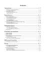
Contents
1 Introduction ............................................................................................1 - 1
1.1 Spindle Drive System Configuration ................................................................................................. 1 - 2
1.1.1 System Configuration................................................................................................................ 1 - 2
1.2 Explanation of Type .......................................................................................................................... 1 - 3
1.2.1 Built-in Spindle Motor Type....................................................................................................... 1 - 3
1.2.2 Encoder Type............................................................................................................................ 1 - 4
2 Specifications.........................................................................................2 - 1
2.1 Built-in Spindle Motor........................................................................................................................ 2 - 2
2.1.1 Environmental Conditions ......................................................................................................... 2 - 2
2.1.2 Precautions for Storage ............................................................................................................ 2 - 2
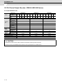
2.1.3 Specifications List ..................................................................................................................... 2 - 3
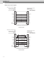
2.1.4 Characteristics ........................................................................................................................ 2 - 19
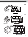
2.1.5 Outline Dimension Drawings................................................................................................... 2 - 27
2.2 PLG Serial Output Encoder (TS5690, MU1606 Series).................................................................. 2 - 32
2.2.1 Specifications List ................................................................................................................... 2 - 32
2.2.2 Outline Dimension Drawings................................................................................................... 2 - 33
3 Dedicated Options .................................................................................3 - 1
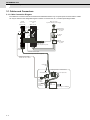
3.1 Cables and Connectors .................................................................................................................... 3 - 2
3.1.1 Cable Connection Diagram....................................................................................................... 3 - 2
3.1.2 List of Cables and Connectors.................................................................................................. 3 - 3
3.2 AC Reactor ....................................................................................................................................... 3 - 5
4 Assembly and Installation.....................................................................4 - 1
4.1 Stator Assembly................................................................................................................................ 4 - 2
4.2 Rotor Assembly................................................................................................................................. 4 - 6
4.3 Motor Assembly ................................................................................................................................ 4 - 9
4.4 Precautions for Handling IPM Spindle Motor .................................................................................. 4 - 12
4.4.1 Precautions ............................................................................................................................. 4 - 12
4.5 Installation of Motor Encoder .......................................................................................................... 4 - 14
4.5.1 Accuracy Encoder (TS5690 Series)........................................................................................ 4 - 14
5 Wiring and Connection..........................................................................5 - 1
5.1 Part System Connection Diagram..................................................................................................... 5 - 3
6 Setup .......................................................................................................6 - 1
6.1 Initial Setup for IPM Spindle Motor ................................................................................................... 6 - 2
6.1.1 Adjustment Procedure .............................................................................................................. 6 - 2
6.1.2 Related Parameters .................................................................................................................. 6 - 5
6.2 Protective Functions List of Units...................................................................................................... 6 - 7
6.2.1 Drive Unit Alarm........................................................................................................................ 6 - 7
6.2.2 Drive Unit Warning.................................................................................................................... 6 - 7
6.2.3 Parameter Numbers during Initial Parameter Error .................................................................. 6 - 8
1
Introduction
1-1
MITSUBISHI CNC
1 Introduction
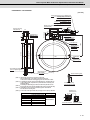
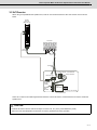
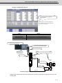
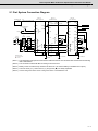
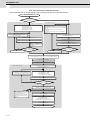
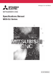
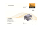
1.1 Spindle Drive System Configuration
1.1.1 System Configuration
Power supply
unit
Spindle
drive unit
(MDS-D2-SP)
MDS-D2 Series:
3-phase 200VAC power supply
(MDS-D2-CV)
Power supply
communication
cable
Circuit protector
(Note) Prepared
by user.
CN24
CN4
CN2
For external
emergency
stop
AC reactor
(D-AL)
CN23
Contactor
(Note) Prepared
by user.
Circuit protector or
protection fuse
(Note) Prepared by user.
Power
connector
Contactor control output
Power cable (Only connector is supplied.)
Spindle encoder cable
< Motor side PLG cable >
Grounding
wire
Crimping terminal + Terminal block
Power cable wire
Thermistor wire
Detection
sensor
TS5690
Detection
gear
MU1606
Built-in
spindle motor
*The wiring is an example.
In the spindle head
1. For coil changeover specification, refer to the section "Spindle coil changeover" in "MDS-D2/DH2 Series
Instruction Manual" (IB-1501127(ENG)).
2. For details on the drive units, refer to "MDS-D2/DH2 Series Specifications Manual" (IB-1501124(ENG)).
CAUTION
1. Keep the detection sensor cable away from the power cable.
2. Connect the ground to the spindle head.
1-2
Built-in Spindle Motor SJ-B Series Specifications and Instruction Manual
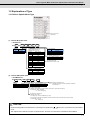
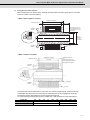
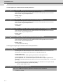
1.2 Explanation of Type
1.2 Explanation of Type
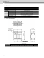
1.2.1 Built-in Spindle Motor Type
QR
code
Date of manufacture
(Year-Month)
Rating nameplate
(1)
Built-in IM spindle motor
< SJ-B Series >
SJ- (1)
(1) Voltage
Symbol
2
4
B
(2)
(3)
(4)
(5)
(6)
(3) Motor size
Stator outline (frame No.) is
indicated with 0 to 9, A, B.
Symbol
Stator outline
0
φ 110
1
φ 128
2
φ 160
3
φ 180
4
φ 210
5
φ 230
6
φ 255
7
φ 300
9
φ 370
A
φ 90
B
φ 115
Voltage
200V
400V
*400V is available by special order.
(6) Coil changeover
Symbol
Coil changeover
None
Unavailable
D
Available (∆-2//∆)
K
Available ( -∆)
(5) Overheat protection sensor
Symbol Overheat protection sensor
T
Thermistor
(4) Specification code
Specification code (01 to 99)
(2) Number of poles
Symbol
Number of poles
2
2 poles
4
4 poles
6
6 poles
(2)
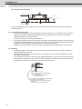
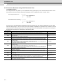
Built-in IPM spindle motor
< SJ-PMB Series >
SJ- (1)
(1) Voltage
Symbol
None
4
PMB
(2)
Voltage
200V
400V
*400V is available by special order.
(3)
(4)
-
(5)
(4) Overheat protection sensor
Symbol Overheat protection sensor
T
Thermistor
(5) Design management No.
Indicates with 2 digits number or alphabetic characters
Example) 00, A1
(3) Base rotation speed
Indicates the thousands and the hundreds places (the ten places are rounded off.)
Example) 03 : 250 to 349 [r/min]
15 : 1450 to 1549 [r/min]
(2) Continuous rated torque
Indicates with 3 digits.
For 1000 [N・ m] or more (for 9999 [N・ m] or less),
the upper digit is indicated by alphabetic character and the others are indicated by the carried number.
Example) 020 : 20 [N・m]
A55 : 1550 [N・ m]
CAUTION
1. Check the rating table to see whether the coil changeover specification (
-
connection, ∆-2//∆connection) is included
or not.
2. This explains the model name system of spindle motors, but does not mean all the combinations are available.
1-3
MITSUBISHI CNC
1 Introduction
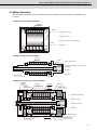
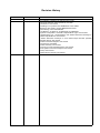
1.2.2 Encoder Type
(1) Spindle side PLG serial output encoder (TS5690, MU1606 Series)
< Sensor type >
TS5690N (1) (2)
(1)
(2)
Symbol
The number of compatible
detection gear teeth
64
12
25
64
128
256
Symbol
10
20
30
40
60
Length of the cable
400mm
800mm
1200mm
1600mm
2000mm
< Detection gear type >
MU1606N (1) (2)
(1)
(2) Each specification number
Symbol
6
7
8
1-4
The number of
detection gear teeth
64
128
256
2
Specifications
2-1
MITSUBISHI CNC
2 Specifications
2.1 Built-in Spindle Motor
2.1.1 Environmental Conditions
Environment
Ambient temperature
Ambient humidity
Storage temperature
Storage humidity
Conditions
0°C to +40°C (with no freezing)
90% RH or less (with no dew condensation)
-20°C to +65°C (with no freezing)
90% RH or less (with no dew condensation)
Atmosphere
Indoors (no direct sunlight);
no corrosive gas, inflammable gas, oil mist or dust
Altitude
Operation/storage: 1000m or less above sea level
Transportation: 10000m or less above sea level
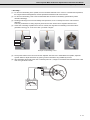
2.1.2 Precautions for Storage
(1) If water, dust or foreign matters, etc., adhere or enter the parts, problems such as rust or decrease in the insulation
resistivity may occur. This will prevent maintenance of satisfying quality and functions.
Always store the motor indoors, and protect the motor by covering it with a sheet, etc.
(2) To prevent the coils from absorbing water and to prevent the steel center and other metallic parts from rusting due
to water entering and internal sweating, place the entire product in a polyethylene bag, etc., insert 0.5kg/m3 of
dehumidifier (silica gel), and seal the bag when storing for six months or longer. Use a dehumidifier that shows the
degree of absorption, and when 50% (changes from blue to pink) is reached, replace the agent, or dry it to use
again.
Remove all dehumidifiers before using the motor again.
(3) Measure the insulation resistivity of the coils before using a stator that has been stored. Confirm that it is 10M
more at room temperature (use a 500V insulation resistance tester). If the insulation resistance is less than 10M
dry the stator in a dryer that does not exceed 90°C until the insulation resistance is restored.
2-2
or
,
Built-in Spindle Motor SJ-B Series Specifications and Instruction Manual
2.1 Built-in Spindle Motor
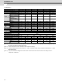
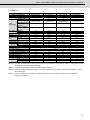
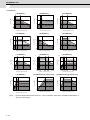
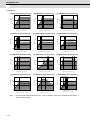
2.1.3 Specifications List
< SJ-B Series >
Built-in spindle motor type (Note 1)
Compatible spindle drive unit
AC reactor for spindle motor
Coil changeover
Continuous rating
Short time rating
Standard output during
acceleration/
deceleration
Actual acceleration/
deceleration output
(Note 4)
Base rotation Continuous
speed [r/min] Short time
Maximum rotation speed
Frame No. - Core width
Torque (Base Continuous
rotation speed)
Short time
[N•m]
Output
capacity [kW]
Rotor
GD2
[kg•m2]
Rotor inertia [kg•m2]
Stator
Mass [kg]
Rotor
Overload capacity (for one minute)
Ambient temperature [°C]
Heat-resistant class
Tolerable vibration
Required cooling capacity (Note 2) [W]
Cooling fluid volume [l/min (20°C)]
Motor total length [mm]
Stator outer diameter [mm]
Rotor inner diameter [mm]
Motor wire size
[mm2]
AWG
SJ-2B4A01T
SJ-2B4002T
SJ-2B4004T
SJ-2B4003T
SJ-2B4B01T
SJ-2B4112T
MDS-D2-SP-80
MDS-D2-SP-20
MDS-D2-SP-40
MDS-D2-SP-40 MDS-D2-SP-160 MDS-D2-SP-40
1.0
0.4
0.75
1.5
2.2
1.5
1.5
0.75
1.5
2.2
3.7
2.2
(15-minute rating) (15-minute rating) (15-minute rating) (15-minute rating) (15-minute rating) (15-minute rating)
2.2
0.75
1.5
2.2
7.5
2.2
2.64
0.9
1.8
2.64
9
2.64
5000
5000
10000
50-55
1.91
3000
3000
10000
63-50
1.27
3000
3000
15000
63-50
2.39
3000
3000
12000
63-90
4.77
5500
5500
10000
70-70
3.82
2500
2500
10000
71-66
5.73
2.86
2.39
4.77
7.00
6.42
8.40
0.00081
0.0031
0.0031
0.0055
0.0065
0.0067
0.00020
0.00078
0.00078
0.00138
0.00163
0.00168
1.9
0.5
2.2
0.9
3.0
1.5
4.1
1.7
2.2
3.9
0.9
1.7
120% of short-time rated output
0 to 40
155(F)
Maximum stationary tolerable value 9.8m/s2(1G), Momentary stationary tolerable value 29.4m/s2(3G)
540
240
530
570
720
570
5
5
5
5
5
5
110
120
120
160
136
146
Φ109.5 (Note 3) Φ109.5 (Note 3) Φ109.5 (Note 3) Φ114.5 (Note 3) Φ127.5 (Note 3)
Φ89.5 (Note 3)
Φ28 (Note 3)
Φ42 (Note 3)
Φ42 (Note 3)
Φ42 (Note 3)
Φ52 (Note 3)
Φ45
1.25
0.75
0.75
0.75
3.5
0.75
16
18
18
18
12
18
(Note 1) Please contact your Mitsubishi Electric dealer for the special products not listed above.
(Note 2) The value for the short-time rated output is shown for the required cooling capacity. Install a cooling jacket around
the stator and use fluid cooling (oil cooling).
(Note 3) These dimensions are the dimensions after machine machining.
(Note 4) Actual acceleration/deceleration output is 1.2-fold of "Standard output during acceleration/deceleration" or "Short
time rated output".
(Note 5) Only the combination designated in this manual can be used for the motor and drive unit. Always use the
designated combination.
2-3
MITSUBISHI CNC
2 Specifications
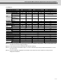
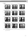
< SJ-B Series >
Built-in spindle motor type (Note 1)
Compatible spindle drive unit
AC reactor for spindle motor
Coil changeover
Continuous rating
Short time rating
Standard output during
acceleration/
deceleration
Actual acceleration/
deceleration output
(Note 4)
Base rotation Continuous
speed [r/min] Short time
Maximum rotation speed
Frame No. - Core width
Torque (Base Continuous
rotation speed)
Short time
[N•m]
Output
capacity [kW]
SJ-2B4111T
SJ-2B4105T
SJ-2B4102T
SJ-2B4201T
SJ-2B4218T
SJ-2B4202T
MDS-D2-SP-80
MDS-D2-SP-80
MDS-D2-SP-80
MDS-D2-SP-40
MDS-D2-SP-80
MDS-D2-SP-80
BKO-NC6783H31
3.7
2.2
1.1
1.5
1.5
2.2
5.5
3.7
3.7
2.2
3.7
3.7
(15-minute rating) (15-minute rating) (10-minute rating) (15-minute rating) (15-minute rating) (15-minute rating)
5.5
3.7
3.7
2.2
3.7
3.7
6.6
4.44
4.44
2.64
4.44
4.44
6000
6000
10000
71-66
5.89
3000
3000
15000
71-120
7.00
1500
1500
15000
71-170
7.00
1500
1500
15000
100-75
9.55
1500
2500
10000
100-75
9.55
1500
1500
15000
100-105
14.0
23.6
14.0
14.1
23.6
8.75
11.8
2
Rotor GD [kg•m ]
0.0067
0.0012
0.0017
0.020
0.020
0.027
Rotor inertia [kg•m2]
Stator
Mass [kg]
Rotor
Overload capacity (for one minute)
Ambient temperature [°C]
Heat-resistant class
0.00168
0.003
0.00425
0.005
0.005
0.0068
4.1
1.7
7.4
3.0
7.1
2.9
10
4.1
2
Tolerable vibration
Required cooling capacity (Note 2) [W]
Cooling fluid volume [l/min (20°C)]
Motor total length [mm]
Stator outer diameter [mm]
Rotor inner diameter [mm]
Motor wire size
[mm2]
AWG
10
7.1
4.3
2.9
120% of short-time rated output
0 to 40
155(F)
Maximum stationary tolerable value 9.8m/s2(1G), Momentary stationary tolerable value 29.4m/s2(3G)
870
700
1530
510
650
830
5
5
5
5
5
5
146
200
250
165
165
195
Φ127.5 (Note 3) Φ127.5 (Note 3) Φ127.5 (Note 3) Φ159.5 (Note 3) Φ159.5 (Note 3) Φ159.5 (Note 3)
Φ45
Φ45
Φ45
Φ60
Φ60
Φ60
3.5
1.25
1.25
0.75
1.25
1.25
12
16
16
18
16
16
(Note 1) Please contact your Mitsubishi Electric dealer for the special products not listed above.
(Note 2) The value for the short-time rated output is shown for the required cooling capacity. Install a cooling jacket around
the stator and use fluid cooling (oil cooling).
(Note 3) These dimensions are the dimensions after machine machining.
(Note 4) Actual acceleration/deceleration output is 1.2-fold of "Standard output during acceleration/deceleration" or "Short
time rated output".
(Note 5) Only the combination designated in this manual can be used for the motor and drive unit. Always use the
designated combination.
2-4
Built-in Spindle Motor SJ-B Series Specifications and Instruction Manual
2.1 Built-in Spindle Motor
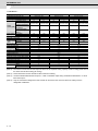
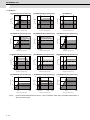
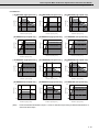
< SJ-B Series >
Built-in spindle motor type (Note 1)
Compatible spindle drive unit
AC reactor for spindle motor
Coil changeover
Continuous rating
Short time rating
Standard output during
acceleration/
deceleration
Actual acceleration/
deceleration output
(Note 4)
Base rotation Continuous
speed [r/min] Short time
Maximum rotation speed [r/min]
Frame No. - Core width
Torque (Base Continuous
rotation speed)
Short time
[N•m]
Output
capacity [kW]
2
SJ-2B4215T
MDS-D2-SP-200
3.7
5.5
(15-minute rating)
SJ-2B4203T
MDS-D2-SP-80
3.7
5.5
(15-minute rating)
SJ-2B4219T
MDS-D2-SP-160
3.7
7.5
(15-minute rating)
SJ-2B4310T
MDS-D2-SP-80
3.7
5.5
(30-minute rating)
11
5.5
7.5
5.5
13.2
6.6
9
6.6
1500
1500
15000
100-135
23.6
1500
1500
15000
100-135
23.6
1500
2000
15000
100-135
23.6
1750
1750
8000
112-125
20.2
35.0
35.0
35.8
30.0
2
Rotor GD [kg•m ]
0.034
0.035
0.035
0.051
Rotor inertia [kg•m2]
Stator
Mass [kg]
Rotor
Overload capacity (for one minute)
Ambient temperature [°C]
Heat-resistant class
0.0085
0.0088
0.0088
0.0128
Tolerable vibration
Required cooling capacity (Note 2) [W]
Cooling fluid volume [l/min (20°C)]
Motor total length [mm]
Stator outer diameter [mm]
Rotor inner diameter [mm]
Motor wire size
[mm2]
AWG
13
5.1
13
13
5.2
5.2
120% of short-time rated output
0 to 40
155(F)
15
5.6
Maximum stationary tolerable value 9.8m/s2(1G), Momentary stationary tolerable value 29.4m/s2(3G)
1240
1180
1340
910
5
5
5
5
230
225
225
230
Φ159.5 (Note 3)
Φ159.5 (Note 3)
Φ159.5 (Note 3)
Φ179.5 (Note 3)
Φ60
Φ60
Φ60
Φ75
8
3.5
3.5
3.5
8
12
12
12
(Note 1) Please contact your Mitsubishi Electric dealer for the special products not listed above.
(Note 2) The value for the short-time rated output is shown for the required cooling capacity. Install a cooling jacket around
the stator and use fluid cooling (oil cooling).
(Note 3) These dimensions are the dimensions after machine machining.
(Note 4) Actual acceleration/deceleration output is 1.2-fold of "Standard output during acceleration/deceleration" or "Short
time rated output".
(Note 5) Only the combination designated in this manual can be used for the motor and drive unit. Always use the
designated combination.
2-5
MITSUBISHI CNC
2 Specifications
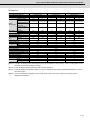
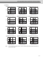
< SJ-B Series >
Built-in spindle motor type (Note 1)
Compatible spindle drive unit
AC reactor for spindle motor
Coil changeover
Continuous rating
Short time rating
Standard output during
acceleration/
deceleration
Actual acceleration/
deceleration output
(Note 4)
Base rotation Continuous
speed [r/min] Short time
Maximum rotation speed [r/min]
Frame No. - Core width
Torque (Base Continuous
rotation speed)
Short time
[N•m]
Output
capacity [kW]
2
SJ-2B4301T
MDS-D2-SP-160
3.7
5.5
(30-minute rating)
SJ-2B4327T
MDS-D2-SP-160
5.5
7.5
(30-minute rating)
SJ-2B4340T
MDS-D2-SP-200
7.5
11
(30-minute rating)
7.5
11
11
9
13.2
13.2
1100
1100
12000
112-125
32.1
1700
1700
8000
112-170
30.9
1500
1500
8000
112-170
47.7
47.7
42.1
70.0
2
Rotor GD [kg•m ]
0.051
0.070
0.070
Rotor inertia [kg•m2]
Stator
Mass [kg]
Rotor
Overload capacity (for one minute)
Ambient temperature [°C]
Heat-resistant class
0.0128
0.0175
0.0175
15
5.6
20
7.6
120% of short-time rated output
0 to 40
155(F)
20
7.6
Tolerable vibration
Required cooling capacity (Note 2) [W]
Cooling fluid volume [l/min (20°C)]
Motor total length [mm]
Stator outer diameter [mm]
Rotor inner diameter [mm]
Motor wire size
[mm2]
AWG
Maximum stationary tolerable value 9.8m/s2(1G), Momentary stationary tolerable value 29.4m/s2(3G)
1510
1140
2500
5
5
10
230
275
270
Φ179.5 (Note 3)
Φ179.5 (Note 3)
Φ179.5 (Note 3)
Φ75
Φ75
Φ80
3.5
5.5
5.5
12
10
10
(Note 1) Please contact your Mitsubishi Electric dealer for the special products not listed above.
(Note 2) The value for the short-time rated output is shown for the required cooling capacity. Install a cooling jacket around
the stator and use fluid cooling (oil cooling).
(Note 3) These dimensions are the dimensions after machine machining.
(Note 4) Actual acceleration/deceleration output is 1.2-fold of "Standard output during acceleration/deceleration" or "Short
time rated output".
(Note 5) Only the combination designated in this manual can be used for the motor and drive unit. Always use the
designated combination.
2-6
Built-in Spindle Motor SJ-B Series Specifications and Instruction Manual
2.1 Built-in Spindle Motor
< SJ-B Series >
Built-in spindle motor type (Note 1)
Compatible spindle drive unit
AC reactor for spindle motor
Coil changeover
Continuous rating
Short time rating
Standard output during
acceleration/
deceleration
Actual acceleration/
deceleration output
(Note 4)
Base rotation Continuous
speed [r/min] Short time
Maximum rotation speed [r/min]
Frame No. - Core width
Torque (Base Continuous
rotation speed)
Short time
[N•m]
Output
capacity [kW]
2
SJ-2B4313TK
SJ-2B4323TK
SJ-2B4325TK
MDS-D2-SP-160
MDS-D2-SP-200
MDS-D2-SP-240
Low-speed coil
High-speed coil
Low-speed coil
High-speed coil
Low-speed coil
High-speed coil
5.5
5.5
5.5
5.5
11
15
7.5
7.5
7.5
7.5
15
22
(30-minute rating) (30-minute rating) (30-minute rating) (30-minute rating) (15-minute rating) (15-minute rating)
7.5
7.5
11
11
15
22
9
9
13.2
13.2
18
26.4
1000
1000
2100
2100
2100
12000
1000
1000
2000
2000
2000
12000
2000
2000
5200
4700
4700
12000
52.5
25.0
52.5
26.3
52.5
30.5
71.6
34.1
71.6
35.8
71.6
44.7
112-170
112-170
112-170
2
Rotor GD [kg•m ]
0.070
0.070
0.070
Rotor inertia [kg•m2]
Stator
Mass [kg]
Rotor
Overload capacity (for one minute)
Ambient temperature [°C]
Heat-resistant class
0.0175
0.0175
0.0175
20
7.6
20
7.6
120% of short-time rated output
0 to 40
155(F)
20
7.6
Tolerable vibration
Required cooling capacity (Note 2) [W]
Cooling fluid volume [l/min (20°C)]
Motor total length [mm]
Stator outer diameter [mm]
Rotor inner diameter [mm]
Motor wire size
[mm2]
AWG
Maximum stationary tolerable value 9.8m/s2(1G), Momentary stationary tolerable value 29.4m/s2(3G)
2200
4400
2640
10
10
10
280
285
295
Φ179.5 (Note 3)
Φ179.5 (Note 3)
Φ179.5 (Note 3)
Φ75
Φ75
Φ75
3.5
8
14
12
8
6
(Note 1) Please contact your Mitsubishi Electric dealer for the special products not listed above.
(Note 2) The value for the short-time rated output is shown for the required cooling capacity. Install a cooling jacket around
the stator and use fluid cooling (oil cooling).
(Note 3) These dimensions are the dimensions after machine machining.
(Note 4) Actual acceleration/deceleration output is 1.2-fold of "Standard output during acceleration/deceleration" or "Short
time rated output".
(Note 5) Only the combination designated in this manual can be used for the motor and drive unit. Always use the
designated combination.
2-7
MITSUBISHI CNC
2 Specifications
< SJ-B Series >
Built-in spindle motor type (Note 1)
Compatible spindle drive unit
AC reactor for spindle motor
Coil changeover
Continuous rating
Short time rating
Standard output during
acceleration/
deceleration
Actual acceleration/
deceleration output
(Note 4)
Base rotation Continuous
speed [r/min] Short time
Maximum rotation speed [r/min]
Frame No. - Core width
Torque (Base Continuous
rotation speed)
Short time
[N•m]
Output
capacity [kW]
2
SJ-2B4303TK
SJ-2B4326TK
SJ-2B4311TK
MDS-D2-SP-200
MDS-D2-SP-240
MDS-D2-SP-320
Low-speed coil
High-speed coil
Low-speed coil
High-speed coil
Low-speed coil
High-speed coil
5.5
5.5
7.5
7.5
15
18.5
7.5
7.5
11
11
18.5
22
(30-minute rating) (30-minute rating) (30-minute rating) (30-minute rating) (15-minute rating) (15-minute rating)
11
15
15
18.5
22
30
13.2
18
18
22.2
26.4
36
680
680
3000
1250
1250
12000
1000
1000
2500
1600
1600
12000
1500
1500
3500
2570
2570
12000
77.2
42.0
71.6
44.8
95.5
68.7
105
57.3
105
65.7
118
81.7
112-220
112-220
112-220
2
Rotor GD [kg•m ]
0.090
0.090
0.090
Rotor inertia [kg•m2]
Stator
Mass [kg]
Rotor
Overload capacity (for one minute)
Ambient temperature [°C]
Heat-resistant class
0.0225
0.0225
0.0225
26
9.8
26
9.8
120% of short-time rated output
0 to 40
155(F)
26
9.8
Tolerable vibration
Required cooling capacity (Note 2) [W]
Cooling fluid volume [l/min (20°C)]
Motor total length [mm]
Stator outer diameter [mm]
Rotor inner diameter [mm]
Motor wire size
[mm2]
AWG
Maximum stationary tolerable value 9.8m/s2(1G), Momentary stationary tolerable value 29.4m/s2(3G)
3200
3330
4120
10
10
10
335
335
345
Φ179.5 (Note 3)
Φ179.5 (Note 3)
Φ179.5 (Note 3)
Φ75
Φ75
Φ75
8
14
14
8
6
6
(Note 1) Please contact your Mitsubishi Electric dealer for the special products not listed above.
(Note 2) The value for the short-time rated output is shown for the required cooling capacity. Install a cooling jacket around
the stator and use fluid cooling (oil cooling).
(Note 3) These dimensions are the dimensions after machine machining.
(Note 4) Actual acceleration/deceleration output is 1.2-fold of "Standard output during acceleration/deceleration" or "Short
time rated output".
(Note 5) Only the combination designated in this manual can be used for the motor and drive unit. Always use the
designated combination.
2-8
Built-in Spindle Motor SJ-B Series Specifications and Instruction Manual
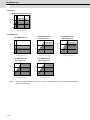
2.1 Built-in Spindle Motor
< SJ-B Series >
Built-in spindle motor type (Note 1)
Compatible spindle drive unit
AC reactor for spindle motor
Coil changeover
Continuous rating
Short time rating
Standard output during
acceleration/
deceleration
Actual acceleration/
deceleration output
(Note 4)
Base rotation Continuous
speed [r/min] Short time
Maximum rotation speed [r/min]
Frame No. - Core width
Torque (Base Continuous
rotation speed)
Short time
[N•m]
Output
capacity [kW]
2
SJ-2B4304TK
SJ-2B4318TK
MDS-D2-SP-320
MDS-D2-SP-320
Low-speed coil
High-speed coil
Low-speed coil
High-speed coil
5.5
5.5
15
18.5
7.5
7.5
18.5
22
(30-minute rating) (30-minute rating) (15-minute rating) (15-minute rating)
SJ-2B4412T
MDS-D2-SP-160
3.7
5.5
(30-minute rating)
15
15
18.5
22
5.5
18
18
22.2
26.4
6.6
450
520
1500
750
750
12000
1200
1200
3000
2500
2500
12000
117
70.0
119
70.7
1500
1500
10000
132-95
23.6
138
95.5
147
84.0
35.0
112-280
112-280
2
Rotor GD [kg•m ]
0.11
0.11
0.077
Rotor inertia [kg•m2]
Stator
Mass [kg]
Rotor
Overload capacity (for one minute)
Ambient temperature [°C]
Heat-resistant class
0.028
0.028
0.0193
33
12
33
12
120% of short-time rated output
0 to 40
155(F)
15
6.2
Tolerable vibration
Required cooling capacity (Note 2) [W]
Cooling fluid volume [l/min (20°C)]
Motor total length [mm]
Stator outer diameter [mm]
Rotor inner diameter [mm]
Motor wire size
[mm2]
AWG
Maximum stationary tolerable value 9.8m/s2(1G), Momentary stationary tolerable value 29.4m/s2(3G)
3870
4950
920
10
10
5
405
405
205
Φ179.5 (Note 3)
Φ179.5 (Note 3)
Φ209.5
Φ75
Φ75
Φ85
14
14
3.5
6
6
12
(Note 1) Please contact your Mitsubishi Electric dealer for the special products not listed above.
(Note 2) The value for the short-time rated output is shown for the required cooling capacity. Install a cooling jacket around
the stator and use fluid cooling (oil cooling).
(Note 3) These dimensions are the dimensions after machine machining.
(Note 4) Actual acceleration/deceleration output is 1.2-fold of "Standard output during acceleration/deceleration" or "Short
time rated output".
(Note 5) Only the combination designated in this manual can be used for the motor and drive unit. Always use the
designated combination.
2-9
MITSUBISHI CNC
2 Specifications
< SJ-B Series >
Built-in spindle motor type (Note 1)
Compatible spindle drive unit
AC reactor for spindle motor
Coil changeover
Continuous rating
Short time rating
Standard output during
acceleration/
deceleration
Actual acceleration/
deceleration output
(Note 4)
Base rotation Continuous
speed [r/min] Short time
Maximum rotation speed [r/min]
Frame No. - Core width
Torque (Base Continuous
rotation speed)
Short time
[N•m]
Output
capacity [kW]
2
SJ-2B4501TK
SJ-2B6611TK
SJ-2B4502TK
MDS-D2-SP-200
MDS-D2-SP-200
MDS-D2-SP-320
Low-speed coil
High-speed coil
Low-speed coil
High-speed coil
Low-speed coil
High-speed coil
7.5
7.5
7.5
7.5
7.5
7.5
11
11
11
11
11
11
(30-minute rating) (30-minute rating) (30-minute rating (30-minute rating) (30-minute rating) (30-minute rating)
15
15
11
15
22
22
18
18
13.2
18
26.4
26.4
700
700
2250
1320
1320
10000
500
500
1500
1030
1030
6000
525
525
3000
1050
1050
10000
102
54.3
143
69.5
136
68.2
150
79.6
210
102
200
100
160-175
160-175
160-230
2
Rotor GD [kg•m ]
0.32
0.41
0.42
Rotor inertia [kg•m2]
Stator
Mass [kg]
Rotor
Overload capacity (for one minute)
Ambient temperature [°C]
Heat-resistant class
0.08
0.102
0.105
29
18
37
19
120% of short-time rated output
0 to 40
155(F)
37
24
Tolerable vibration
Required cooling capacity (Note 2) [W]
Cooling fluid volume [l/min (20°C)]
Motor total length [mm]
Stator outer diameter [mm]
Rotor inner diameter [mm]
Motor wire size
[mm2]
AWG
Maximum stationary tolerable value 9.8m/s2(1G), Momentary stationary tolerable value 29.4m/s2(3G)
3850
3520
4730
10
10
10
320
320
380
Φ229.5 (Note3 )
Φ254.5 (Note 3)
Φ229.5 (Note 3)
Φ95
Φ110
Φ95
8
8
14
8
8
6
(Note 1) Please contact your Mitsubishi Electric dealer for the special products not listed above.
(Note 2) The value for the short-time rated output is shown for the required cooling capacity. Install a cooling jacket around
the stator and use fluid cooling (oil cooling).
(Note 3) These dimensions are the dimensions after machine machining.
(Note 4) Actual acceleration/deceleration output is 1.2-fold of "Standard output during acceleration/deceleration" or "Short
time rated output".
(Note 5) Only the combination designated in this manual can be used for the motor and drive unit. Always use the
designated combination.
2 - 10
Built-in Spindle Motor SJ-B Series Specifications and Instruction Manual
2.1 Built-in Spindle Motor
< SJ-B Series >
Built-in spindle motor type (Note 1)
Compatible spindle drive unit
AC reactor for spindle motor
Coil changeover
Continuous rating
Short time rating
Standard output during
acceleration/
deceleration
Actual acceleration/
deceleration output
(Note 4)
Base rotation Continuous
speed [r/min] Short time
Maximum rotation speed [r/min]
Frame No. - Core width
Torque (Base Continuous
rotation speed)
Short time
[N•m]
Output
capacity [kW]
SJ-2B6602TK
SJ-2B4601TK
SJ-2B6605TK
MDS-D2-SP-320
MDS-D2-SP-320
MDS-D2-SP-240
Low-speed coil
High-speed coil
Low-speed coil
High-speed coil
Low-speed coil
High-speed coil
11
11
22
22
11
11
15
15
26
26
15
15
(30-minute rating) (30-minute rating) (30-minute rating) (30-minute rating) (30-minute rating) (30-minute rating)
15
22
26
26
15
15
18
26.4
31.2
31.2
18
18
550
550
2000
1193
1193
8000
1250
1250
3500
3000
3000
10000
440
440
1500
1000
1000
6000
191
88.0
168
70.0
239
105
260
120
199
82.8
326
143
160-230
160-230
160-295
2
Rotor GD [kg•m ]
0.53
0.42
0.69
Rotor inertia [kg•m2]
Stator
Mass [kg]
Rotor
Overload capacity (for one minute)
Ambient temperature [°C]
Heat-resistant class
0.133
0.105
0.173
49
25
55
24
120% of short-time rated output
0 to 40
155(F)
63
33
2
Tolerable vibration
Required cooling capacity (Note 2) [W]
Cooling fluid volume [l/min (20°C)]
Motor total length [mm]
Stator outer diameter [mm]
Rotor inner diameter [mm]
Motor wire size
[mm2]
AWG
Maximum stationary tolerable value 9.8m/s2(1G), Momentary stationary tolerable value 29.4m/s2(3G)
3810
3270
4450
10
10
10
380
380
440
Φ254.5 (Note 3)
Φ254.5 (Note 3)
Φ254.5 (Note 3)
Φ110
Φ95
Φ110
14
14
8
6
6
8
(Note 1) Please contact your Mitsubishi Electric dealer for the special products not listed above.
(Note 2) The value for the short-time rated output is shown for the required cooling capacity. Install a cooling jacket around
the stator and use fluid cooling (oil cooling).
(Note 3) These dimensions are the dimensions after machine machining.
(Note 4) Actual acceleration/deceleration output is 1.2-fold of "Standard output during acceleration/deceleration" or "Short
time rated output".
(Note 5) Only the combination designated in this manual can be used for the motor and drive unit. Always use the
designated combination.
2 - 11
MITSUBISHI CNC
2 Specifications
< SJ-B Series >
Built-in spindle motor type (Note 1)
Compatible spindle drive unit
AC reactor for spindle motor
Coil changeover
Continuous rating
Short time rating
Standard output during
acceleration/
deceleration
Actual acceleration/
deceleration output
(Note 4)
Base rotation Continuous
speed [r/min] Short time
Maximum rotation speed [r/min]
Frame No. - Core width
Torque (Base Continuous
rotation speed)
Short time
[N•m]
Output
capacity [kW]
2
SJ-2B4503TK
SJ-2B6603TK
SJ-2B4602TK
MDS-D2-SP-320
MDS-D2-SP-320
MDS-D2-SP-320
Low-speed coil
High-speed coil
Low-speed coil
High-speed coil
Low-speed coil
High-speed coil
11
15
15
15
18.5
18.5
15
22
22
22
22
22
(30-minute rating) (30-minute rating) (30-minute rating) (30-minute rating) (30-minute rating) (30-minute rating)
15
22
22
22
22
22
18
26.4
26.4
26.4
26.4
26.4
475
475
2000
1250
1250
10000
600
600
1500
1200
1200
6000
720
720
2000
1500
1500
10000
221
115
239
119
245
118
302
168
350
175
292
140
160-295
160-295
160-295
2
Rotor GD [kg•m ]
0.54
0.69
0.54
Rotor inertia [kg•m2]
Stator
Mass [kg]
Rotor
Overload capacity (for one minute)
Ambient temperature [°C]
Heat-resistant class
0.135
0.173
0.135
48
31
63
33
120% of short-time rated output
0 to 40
155(F)
71
31
Tolerable vibration
Required cooling capacity (Note 2) [W]
Cooling fluid volume [l/min (20°C)]
Motor total length [mm]
Stator outer diameter [mm]
Rotor inner diameter [mm]
Motor wire size
[mm2]
AWG
Maximum stationary tolerable value 9.8m/s2(1G), Momentary stationary tolerable value 29.4m/s2(3G)
7220
5160
4500
10
15
10
445
445
440
Φ229.5 (Note 3)
Φ254.5 (Note 3)
Φ254.5 (Note 3)
Φ95
Φ110
Φ95
14
14
14
6
6
6
(Note 1) Please contact your Mitsubishi Electric dealer for the special products not listed above.
(Note 2) The value for the short-time rated output is shown for the required cooling capacity. Install a cooling jacket around
the stator and use fluid cooling (oil cooling).
(Note 3) These dimensions are the dimensions after machine machining.
(Note 4) Actual acceleration/deceleration output is 1.2-fold of "Standard output during acceleration/deceleration" or "Short
time rated output".
(Note 5) Only the combination designated in this manual can be used for the motor and drive unit. Always use the
designated combination.
2 - 12
Built-in Spindle Motor SJ-B Series Specifications and Instruction Manual
2.1 Built-in Spindle Motor
< SJ-B Series >
Built-in spindle motor type (Note 1)
Compatible spindle drive unit
AC reactor for spindle motor
Coil changeover
Continuous rating
Short time rating
Standard output during
acceleration/
deceleration
Actual acceleration/
deceleration output
(Note 4)
Base rotation Continuous
speed [r/min] Short time
Maximum rotation speed [r/min]
Frame No. - Core width
Torque (Base Continuous
rotation speed)
Short time
[N•m]
Output
capacity [kW]
2
SJ-2B4511TK
SJ-2B6720TK
SJ-2B6705TK
MDS-D2-SP-320
MDS-D2-SP-320
MDS-D2-SP-200
Low-speed coil
High-speed coil
Low-speed coil
High-speed coil
Low-speed coil
High-speed coil
15
22
15
22
7.5
7.5
22
30
22
26
11
11
(10-minute rating) (30-minute rating) (30-minute rating) (30-minute rating) (30-minute rating) (30-minute rating)
22
30
22
26
11
11
26.4
36
26.4
31.2
13.2
13.2
600
600
2000
1600
1600
10000
700
700
1500
1550
1550
4500
270
270
750
540
540
4500
239
131
205
136
265
133
350
179
300
160
389
195
160-330
180-160
180-230
2
Rotor GD [kg•m ]
0.60
0.80
1.15
Rotor inertia [kg•m2]
Stator
Mass [kg]
Rotor
Overload capacity (for one minute)
Ambient temperature [°C]
Heat-resistant class
0.15
0.20
0.288
54
34
45
26
120% of short-time rated output
0 to 40
155(F)
65
38
Tolerable vibration
Required cooling capacity (Note 2) [W]
Cooling fluid volume [l/min (20°C)]
Motor total length [mm]
Stator outer diameter [mm]
Rotor inner diameter [mm]
Motor wire size
[mm2]
AWG
Maximum stationary tolerable value 9.8m/s2(1G), Momentary stationary tolerable value 29.4m/s2(3G)
8160
5200
4440
15
15
10
480
300
400
Φ229.5 (Note 3)
Φ299.5 (Note 3)
Φ299.5 (Note 3)
Φ95
Φ130
Φ130
14
14
14
6
6
6
(Note 1) Please contact your Mitsubishi Electric dealer for the special products not listed above.
(Note 2) The value for the short-time rated output is shown for the required cooling capacity. Install a cooling jacket around
the stator and use fluid cooling (oil cooling).
(Note 3) These dimensions are the dimensions after machine machining.
(Note 4) Actual acceleration/deceleration output is 1.2-fold of "Standard output during acceleration/deceleration" or "Short
time rated output".
(Note 5) Only the combination designated in this manual can be used for the motor and drive unit. Always use the
designated combination.
2 - 13
MITSUBISHI CNC
2 Specifications
< SJ-B Series >
Built-in spindle motor type (Note 1)
Compatible spindle drive unit
AC reactor for spindle motor
Coil changeover
Continuous rating
Short time rating
Standard output during
acceleration/
deceleration
Actual acceleration/
deceleration output
(Note 4)
Base rotation Continuous
speed [r/min] Short time
Maximum rotation speed [r/min]
Frame No. - Core width
Torque (Base Continuous
rotation speed)
Short time
[N•m]
Output
capacity [kW]
2
SJ-2B6711TK
SJ-2B6706TK
SJ-2B6716TK
MDS-D2-SP-320
MDS-D2-SP-400
MDS-D2-SP-400
Low-speed coil
High-speed coil
Low-speed coil
High-speed coil
Low-speed coil
High-speed coil
11
11
15
15
15
22
15
15
18.5
18.5
22
26
(30-minute rating) (30-minute rating) (30-minute rating) (30-minute rating) (30-minute rating) (30-minute rating)
22
22
26
30
26
30
26.4
26.4
31.2
36
31.2
36
400
500
1700
920
920
5000
450
450
2000
1080
1080
6000
350
420
600
600
600
4000
263
114
318
133
409
350
286
156
393
164
500
414
180-230
180-230
180-250
2
Rotor GD [kg•m ]
1.12
1.15
1.13
Rotor inertia [kg•m2]
Stator
Mass [kg]
Rotor
Overload capacity (for one minute)
Ambient temperature [°C]
Heat-resistant class
0.280
0.288
0.283
65
37
65
38
120% of short-time rated output
0 to 40
155(F)
70
35
Tolerable vibration
Required cooling capacity (Note 2) [W]
Cooling fluid volume [l/min (20°C)]
Motor total length [mm]
Stator outer diameter [mm]
Rotor inner diameter [mm]
Motor wire size
[mm2]
AWG
Maximum stationary tolerable value 9.8m/s2(1G), Momentary stationary tolerable value 29.4m/s2(3G)
3270
4620
7560
10
10
15
405
405
390
Φ299.5 (Note 3)
Φ299.5 (Note 3)
Φ299.5 (Note 3)
Φ130
Φ130
Φ145
22
22
22
4
4
4
(Note 1) Please contact your Mitsubishi Electric dealer for the special products not listed above.
(Note 2) The value for the short-time rated output is shown for the required cooling capacity. Install a cooling jacket around
the stator and use fluid cooling (oil cooling).
(Note 3) These dimensions are the dimensions after machine machining.
(Note 4) Actual acceleration/deceleration output is 1.2-fold of "Standard output during acceleration/deceleration" or "Short
time rated output".
(Note 5) Only the combination designated in this manual can be used for the motor and drive unit. Always use the
designated combination.
2 - 14
Built-in Spindle Motor SJ-B Series Specifications and Instruction Manual
2.1 Built-in Spindle Motor
< SJ-B Series >
Built-in spindle motor type (Note 1)
Compatible spindle drive unit
AC reactor for spindle motor
Coil changeover
Continuous rating
Short time rating
Standard output during
acceleration/
deceleration
Actual acceleration/
deceleration output
(Note 4)
Base rotation Continuous
speed [r/min] Short time
Maximum rotation speed [r/min]
Frame No. - Core width
Torque (Base Continuous
rotation speed)
Short time
[N•m]
Output
capacity [kW]
2
SJ-2B6721TK
SJ-2B6704TK
SJ-2B6709TK
MDS-D2-SP-320
MDS-D2-SP-320
MDS-D2-SP-400
Low-speed coil
High-speed coil
Low-speed coil
High-speed coil
Low-speed coil
High-speed coil
18.5
22
15
22
15
22
22
30
22
30
22
30
(30-minute rating) (30-minute rating) (30-minute rating) (30-minute rating) (30-minute rating) (30-minute rating)
22
30
22
30
22
30
26.4
36
26.4
36
26.4
36
500
500
1500
1500
1500
6000
475
475
1150
1200
1200
6000
350
420
1500
1000
1000
6000
353
140
302
175
409
210
420
191
442
239
500
286
180-250
180-295
180-295
2
Rotor GD [kg•m ]
1.13
1.48
1.48
Rotor inertia [kg•m2]
Stator
Mass [kg]
Rotor
Overload capacity (for one minute)
Ambient temperature [°C]
Heat-resistant class
0.283
0.37
0.37
70
35
83
49
120% of short-time rated output
0 to 40
155(F)
83
49
Tolerable vibration
Required cooling capacity (Note 2) [W]
Cooling fluid volume [l/min (20°C)]
Motor total length [mm]
Stator outer diameter [mm]
Rotor inner diameter [mm]
Motor wire size
[mm2]
AWG
Maximum stationary tolerable value 9.8m/s2(1G), Momentary stationary tolerable value 29.4m/s2(3G)
5230
5210
6180
15
15
15
390
470
450
Φ299.5 (Note 3)
Φ299.5 (Note 3)
Φ299.5 (Note 3)
Φ145
Φ130
Φ130
22
22
22
4
4
4
(Note 1) Please contact your Mitsubishi Electric dealer for the special products not listed above.
(Note 2) The value for the short-time rated output is shown for the required cooling capacity. Install a cooling jacket around
the stator and use fluid cooling (oil cooling).
(Note 3) These dimensions are the dimensions after machine machining.
(Note 4) Actual acceleration/deceleration output is 1.2-fold of "Standard output during acceleration/deceleration" or "Short
time rated output".
(Note 5) Only the combination designated in this manual can be used for the motor and drive unit. Always use the
designated combination.
2 - 15
MITSUBISHI CNC
2 Specifications
< SJ-B Series >
Built-in spindle motor type (Note 1)
Compatible spindle drive unit
AC reactor for spindle motor
Coil changeover
Continuous rating
Short time rating
Standard output during
acceleration/
deceleration
Actual acceleration/
deceleration output
(Note 4)
Base rotation Continuous
speed [r/min] Short time
Maximum rotation speed [r/min]
Frame No. - Core width
Torque (Base Continuous
rotation speed)
Short time
[N•m]
Output
capacity [kW]
2
SJ-2B6802TK
SJ-2B6905TK
MDS-D2-SP-640
MDS-D2-SP-320
Low-speed coil
High-speed coil
Low-speed coil
High-speed coil
30
30
22
22
37
37
26
26
(30-minute rating) (30-minute rating) (30-minute rating) (30-minute rating)
SJ-2B6908TK
MDS-D2-SP-320
Low-speed coil
High-speed coil
15
22
22
30
(50%ED rating)
(50%ED rating)
37
37
26
26
22
30
44.4
44.4
31.2
31.2
26.4
36
400
400
1000
650
650
3200
420
420
1500
1000
1000
4000
175
175
1000
450
450
3300
716
441
500
210
819
467
883
544
591
248
1200
637
200-350
225-270
225-350
2
Rotor GD [kg•m ]
2.70
3.41
4.42
Rotor inertia [kg•m2]
Stator
Mass [kg]
Rotor
Overload capacity (for one minute)
Ambient temperature [°C]
Heat-resistant class
0.675
0.853
1.105
116
72
110
70
120% of short-time rated output
0 to 40
155(F)
143
91
Tolerable vibration
Required cooling capacity (Note 2) [W]
Cooling fluid volume [l/min (20°C)]
Motor total length [mm]
Stator outer diameter [mm]
Rotor inner diameter [mm]
Motor wire size
[mm2]
AWG
Maximum stationary tolerable value 9.8m/s2(1G), Momentary stationary tolerable value 29.4m/s2(3G)
8450
4040
9920
15
10
15
550
465
545
Φ329.5 (Note 3)
Φ369.5 (Note 3)
Φ369.5 (Note 3)
Φ145
Φ165
Φ165
38
22
22
2
4
4
(Note 1) Please contact your Mitsubishi Electric dealer for the special products not listed above.
(Note 2) The value for the short-time rated output is shown for the required cooling capacity. Install a cooling jacket around
the stator and use fluid cooling (oil cooling).
(Note 3) These dimensions are the dimensions after machine machining.
(Note 4) Actual acceleration/deceleration output is 1.2-fold of "Standard output during acceleration/deceleration" or "Short
time rated output".
(Note 5) Only the combination designated in this manual can be used for the motor and drive unit. Always use the
designated combination.
2 - 16
Built-in Spindle Motor SJ-B Series Specifications and Instruction Manual
2.1 Built-in Spindle Motor
< SJ-B Series >
Built-in spindle motor type (Note 1)
Compatible spindle drive unit
AC reactor for spindle motor
Coil changeover
Continuous rating
Short time rating
Standard output during
acceleration/
deceleration
Actual acceleration/
deceleration output
(Note 4)
Base rotation Continuous
speed [r/min] Short time
Maximum rotation speed [r/min]
Frame No. - Core width
Torque (Base Continuous
rotation speed)
Short time
[N•m]
Output
capacity [kW]
2
SJ-2B6906TK
MDS-D2-SP-400
Low-speed coil
High-speed coil
15
30
22
37
(30-minute rating)
(30-minute rating)
SJ-2B6914TK
MDS-D2-SP-640
Low-speed coil
High-speed coil
25
25
30
30
(30-minute rating)
(30-minute rating)
22
37
30
30
26.4
44.4
36
36
175
175
1000
600
600
3300
240
240
1000
470
470
3300
819
477
995
508
1200
589
1194
610
225-350
225-350
2
Rotor GD [kg•m ]
4.42
4.42
Rotor inertia [kg•m2]
Stator
Mass [kg]
Rotor
Overload capacity (for one minute)
Ambient temperature [°C]
Heat-resistant class
1.105
1.105
143
91
143
91
120% of short-time rated output
0 to 40
155(F)
Maximum stationary tolerable value 9.8m/s2(1G),
Tolerable vibration
Momentary stationary tolerable value 29.4m/s2(3G)
Required cooling capacity (Note 2) [W]
Cooling fluid volume [l/min (20°C)]
Motor total length [mm]
Stator outer diameter [mm]
Rotor inner diameter [mm]
9820
15
555
Φ369.5 (Note 3)
Φ165
9480
15
520
Φ369.5 (Note 3)
Φ165
[mm2]
AWG
38
38
2
2
Motor wire size
(Note 1) Please contact your Mitsubishi Electric dealer for the special products not listed above.
(Note 2) The value for the short-time rated output is shown for the required cooling capacity. Install a cooling jacket around
the stator and use fluid cooling (oil cooling).
(Note 3) These dimensions are the dimensions after machine machining.
(Note 4) Actual acceleration/deceleration output is 1.2-fold of "Standard output during acceleration/deceleration" or "Short
time rated output".
(Note 5) Only the combination designated in this manual can be used for the motor and drive unit. Always use the
designated combination.
2 - 17
MITSUBISHI CNC
2 Specifications
< SJ-PMB Series>
Built-in spindle motor type (Note 1)
Compatible spindle drive unit
AC reactor for spindle motor
Coil changeover
Continuous rating
Short time rating
Standard output during
acceleration/
deceleration
Actual acceleration/
deceleration output
(Note 4)
Base rotation Continuous
speed [r/min] Short time
Maximum rotation speed [r/min]
Frame No. - Core width
Torque (Base Continuous
rotation speed)
Short time
[N•m]
Output
capacity [kW]
2
SJ-PMB02215T-02
MDS-D2-SP-240
3.5
5.5
(50%ED rating)
SJ-PMB04412T-B0
MDS-D2-SP-200
Low-speed coil
High-speed coil
5.5
5.5
7.5
7.5
(25%ED rating)
(25%ED rating)
SJ-PMB14007T-01
MDS-D2-SP-320
Low-speed coil
High-speed coil
11
11
15
15
(15%ED rating)
(15%ED rating)
5.5
7.5
7.5
15
15
6.6
9
9
18
18
1500
1500
10000
80
22.3
1200
1200
3000
3000
3000
8000
750
750
1800
1800
1800
6000
43.8
17.5
140
58.4
35.0
59.7
23.9
191(15%ED rating)
79.6(15%ED rating)
112
160
2
Rotor GD [kg•m ]
0.024
0.0649
0.253
Rotor inertia [kg•m2]
Stator
Mass [kg]
Rotor
Overload capacity (for one minute)
Ambient temperature [°C]
Heat-resistant class
0.006
0.0162
0.0633
Tolerable vibration
Required cooling capacity (Note 2) [W]
Cooling fluid volume [l/min (20°C)]
Motor total length [mm]
Stator outer diameter [mm]
Rotor inner diameter [mm]
Motor wire size
[mm2]
AWG
4.4
3.7
14.0
8.0
120% of short-time rated output
0 to 40
155(F)
30
15
Maximum stationary tolerable value 9.8m/s2(1G), Momentary stationary tolerable value 29.4m/s2(3G)
1400
1200
1500
5
5
5
150
225
250
Φ139.5
Φ179.5
Φ254.5
Φ60
Φ70.6
Φ95
8
14
14
8
6
6
(Note 1) Please contact your Mitsubishi Electric dealer for the special products not listed above.
(Note 2) The value for the short-time rated output is shown for the required cooling capacity. Install a cooling jacket around
the stator and use fluid cooling (oil cooling).
(Note 3) Only the combination designated in this manual can be used for the motor and drive unit. Always use the
designated combination.
(Note 4) Actual acceleration/deceleration output is 1.2-fold of "Standard output during acceleration/deceleration" or "Short
time rated output".
2 - 18
Built-in Spindle Motor SJ-B Series Specifications and Instruction Manual
2.1 Built-in Spindle Motor
2.1.4 Characteristics
< SJ-B Series >
[ SJ-2B4A01T ]
[ SJ-2B4002T ]
[ SJ-2B4004T ]
3
0.9
3
1
15-minute rating
0.6
0.4
Continuous rating
0.3
Output [kW]
2
Output [kW]
Output [kW]
0.75
2.2
Standard output during
5-minute acceleration/deceleration
1.5
rating
15-minute rating
1.0
2
1.5
15-minute rating
1
0.75
Continuous rating
Continuous rating
0
0
0
3400
5000
10000
3000
10000
3000
Rotation speed [r/ min]
Rotation speed [r/ min]
[ SJ-2B4003T ]
[ SJ-2B4B01T ]
[ SJ-2B4112T ]
9
3
15000
Rotation speed [r/ min]
3
7.5
1.5
15-minute rating
Continuous rating
1
Standard output during
acceleration/deceleration
6
3-minute
rating
3.7
15-minute rating
2.2
3
2.2
Output [kW]
2
Output [kW]
Output [kW]
2.2
2
1.5
15-minute rating
Continuous rating
1
Continuous rating
0
0
3000
[ SJ-2B4111T ]
2500
[ SJ-2B4102T ]
4
6
3.7
15-minute rating
2.2
2
Output [kW]
5.5
10-minute rating
3.7
Continuous
rating
10000
Rotation speed [r/ min]
[ SJ-2B4105T ]
Output [kW]
Output [kW]
10000
6
9
3
5000 5500
Rotation speed [r/ min]
Rotation speed [r/ min]
6
0
2500
12000
4
3.7
10-minute rating
2
1.1
Continuous rating
Continuous rating
0
0
6000
Rotation speed [r/ min]
(Note)
10000
0
3000
12000 15000
Rotation speed [r/ min]
1500
6000
15000
Rotation speed [r/ min]
Actual acceleration/deceleration output is 1.2-fold of "Standard output during acceleration/deceleration" or
"Short time rated output".
2 - 19
MITSUBISHI CNC
2 Specifications
< SJ-B Series >
[ SJ-2B4201T ]
[ SJ-2B4218T ]
[ SJ-2B4202T ]
6
3
6
15-minute rating
1.5
Continuous rating
4
3.7
15-minute rating
2
1.5
Output [kW]
1
Output [kW]
Output [kW]
2.2
2
4
2.2
2
Continuous rating
Continuous rating
0
0
1500
6000
15000
0
1500 2500
10000
1500
Rotation speed [r/ min]
Rotation speed [r/ min]
[ SJ-2B4215T ]
15000
6000
Rotation speed [r/ min]
[ SJ-2B4203T ]
15
3.7
15-minute rating
[ SJ-2B4219T ]
9
9
7.5
Standard output during
acceleration/deceleration
5.5
5
15-minute rating
3.7
6
Output [kW]
10
15-minute rating
Output [kW]
Output [kW]
11
5.5
15-minute rating
3.7
3
6
3.7
3
Continuous rating
Continuous rating
Continuous rating
0
15000
7500
1500
Rotation speed [r/ min]
[ SJ-2B4310T ]
[ SJ-2B4301T ]
30-minute rating
3.7
3
15000
[ SJ-2B4327T ]
15
7.5
Standard output during
acceleration/deceleration
5.5
30-minute rating
3.7
6
3
Output [kW]
Output [kW]
5.5
6000
Rotation speed [r/ min]
9
15-minute
rating
Output [kW]
15000
4500
Rotation speed [r/ min]
9
6
0
1500 2000
0
1500 3000
Continuous rating
10
15-minute 11
rating
Standard output during
acceleration/deceleration
7.5
5.5
5
30-minute rating
Continuous rating
Continuous rating
0
0
1500 1750
4500
8000
0
1100 1500
Continuous rating
5
0
6
7.5
30-minute rating
5.5
Continuous rating
3
0
1350 1500
7500 8000
Rotation speed [r/ min]
Output [kW]
7.5
30-minute rating
Output [kW]
Output [kW]
10
9
7.5
11
2 - 20
[ SJ-2B4313TK (high-speed coil) ]
9
15-minute rating
6600 8000
Rotation speed [r/ min]
[ SJ-2B4313TK (low-speed coil) ]
15
(Note)
1500 1700 2200
12000
Rotation speed [r/ min]
Rotation speed [r/ min]
[ SJ-2B4340T ]
6000 8180
6
30-minute rating
5.5
Continuous rating
3
0
1000
Rotation speed [r/ min]
2100
2100
8000
Rotation speed [r/ min]
12000
Actual acceleration/deceleration output is 1.2-fold of "Standard output during acceleration/deceleration" or
"Short time rated output".
Built-in Spindle Motor SJ-B Series Specifications and Instruction Manual
2.1 Built-in Spindle Motor
< SJ-B Series >
[ SJ-2B4323TK (low-speed coil) ]
[ SJ-2B4323TK (high-speed coil) ]
30
11
10-minute rating
7.5
30-minute rating
5.5
5
25%ED rating
Output [kW]
10
Output [kW]
11
Output [kW]
[ SJ-2B4325TK (low-speed coil) ]
15
15
10
7.5
10-minute rating
5.5
30-minute rating
5
Continuous rating
11
0
2000
8000
Rotation speed [r/ min]
Rotation speed [r/ min]
1450 2000
12000
4500 5200
Rotation speed [r/ min]
[ SJ-2B4303TK (low-speed coil) ]
[ SJ-2B4303TK (high-speed coil) ]
18
30
15-minute rating
10
Continuous rating
0
2100
[ SJ-2B4325TK (high-speed coil) ]
15
Continuous rating
0
1000
20
18
15
15
15-minute rating
Continuous rating
10
12
11
Standard output during
7.5 acceleration/deceleration
30-minute rating
5.5
6
Output [kW]
Output [kW]
20
Output [kW]
40%ED rating
22
12
Standard output during
acceleration/deceleration
7.5
30-minute rating
5.5
Continuous rating
6
Continuous rating
4700
Rotation speed [r/ min]
530 680 780
12000
1250 2500
30
30-minute rating
7.5
Continuous rating
7
15%ED
rating
14
Standard output during
acceleration/deceleration
Output [kW]
11
during acceleration/
deceleration
11
7.5
30-minute rating
7
2500
1600 2700
15 15-minute rating
Continuous rating
10
8000
1060 1260 1500
12000
Rotation speed [r/ min]
Rotation speed [r/ min]
[ SJ-2B4311TK (high-speed coil) ]
[ SJ-2B4304TK (high-speed coil) ]
18
18
15
Standard output
during acceleration/
deceleration
25%ED
rating
12
7.5
6
5.5
30-minute rating
15
Output [kW]
Output [kW]
Continuous rating
12
0
2570 3500
9000
Rotation speed [r/ min]
(Note)
12000
Standard output during
acceleration/deceleration
7.5
6
Continuous rating
0
3150 3500
Rotation speed [r/ min]
[ SJ-2B4304TK(low-speed coil) ]
36
30
Standard output during
acceleration/deceleration
22
18.5 15-minute rating
18.5
0
0
12
20
Standard output
during acceleration/
22 deceleration
Continuous rating
0
770 1000 1050
12000
[ SJ-2B4311TK(low-speed coil) ]
18.5
Output [kW]
14
8000
Rotation speed [r/ min]
21
40%ED rating
15 Standard output
Output [kW]
3000
[ SJ-2B4326TK (high-speed coil) ]
21
Output [kW]
2300
Rotation speed [r/ min]
[ SJ-2B4326TK (low-speed coil) ]
24
0
0
0
5.5 30-minute rating
Continuous rating
0
350 450 520 700
Rotation speed [r/ min]
1500
750 1500
6000
12000
Rotation speed [r/ min]
Actual acceleration/deceleration output is 1.2-fold of "Standard output during acceleration/deceleration" or
"Short time rated output".
2 - 21
MITSUBISHI CNC
2 Specifications
< SJ-B Series >
[ SJ-2B4318TK (low-speed coil) ]
[ SJ-2B4318TK (high-speed coil) ]
30
[ SJ-2B4412T ]
9
30
25%ED rating
Continuous rating
10
Continuous rating
10
0
2500 3000
2500
[ SJ-2B4501TK (low-speed coil) ]
30-minute rating
7.5
Continuous rating
0
12
Continuous rating
15-minute rating
30-minute rating
6
[ SJ-2B4502TK (high-speed coil) ]
30
22
20
Standard output during
acceleration/deceleration
11
10
7.5
30-minute rating
Output [kW]
Output [kW]
22
Continuous rating
20
Standard output during
acceleration/deceleration
11
10
7.5
0
0
1030 1400
525
4200 5730 6000
Rotation speed [r/ min]
1050 2100
3000
1050
[ SJ-2B6602TK (high-speed coil) ]
30
10000
Rotation speed [r/ min]
Rotation speed [r/ min]
[ SJ-2B6602TK (low-speed coil) ]
30-minute rating
Continuous rating
Continuous rating
0
1500
Rotation speed [r/ min]
30
15
Standard output during
acceleration/deceleration
11
30-minute rating
7.5
Continuous rating
460 500
10000
[ SJ-2B4502TK (low-speed coil) ]
18
11
7.5
Rotation speed [r/ min]
[ SJ-2B6611TK (high-speed coil) ]
6
12
0
1320 1800
Rotation speed [r/ min]
Output [kW]
18
15
Standard output during
acceleration/deceleration
11
30-minute rating
7.5
6
2250
8180 10000
[ SJ-2B6611TK (low-speed coil) ]
0
700 950
Continuous rating
Rotation speed [r/ min]
Output [kW]
Standard output
during acceleration/
11 deceleration
Output [kW]
Output [kW]
15
30-minute rating
1500
18
6
3
10000 12000
[ SJ-2B4501TK (high-speed coil) ]
18
5.5
3.7
Rotation speed [r/ min]
Rotation speed [r/ min]
12
6
0
0
900 1200
12
18.5 15-minute rating
20
Output [kW]
18.5
15 15-minute rating
Output [kW]
Output [kW]
22
20
[ SJ-2B4601TK (low-speed coil) ]
30
30
15
11
30-minute rating
10
20
11
10
30-minute rating
Continuous rating
22
Output [kW]
20
Output [kW]
Output [kW]
26
22
Standard output during
acceleration/deceleration
15
30-minute rating
20
Continuous rating
10
Continuous rating
0
Rotation speed [r/ min]
(Note)
2 - 22
0
0
550
2000
1193 1750
5500
Rotation speed [r/ min]
8000
1250
3500
Rotation speed [r/ min]
Actual acceleration/deceleration output is 1.2-fold of "Standard output during acceleration/deceleration" or
"Short time rated output".
Built-in Spindle Motor SJ-B Series Specifications and Instruction Manual
2.1 Built-in Spindle Motor
< SJ-B Series >
[ SJ-2B4601TK (high-speed coil) ]
[ SJ-2B6605TK (low-speed coil) ]
30
18
26
15
30-minute rating
Continuous rating
10
0
15
30-minute rating
11
12
Output [kW]
20
Output [kW]
22
Output [kW]
[ SJ-2B6605TK (high-speed coil) ]
18
Continuous rating
6
0
3000
Continuous rating
6
1000
440
1500
1000
Rotation speed [r/ min]
[ SJ-2B4503TK (low-speed coil) ]
30
15
11 30-minute rating
10
10
Output [kW]
Output [kW]
Output [kW]
22
20
6000
[ SJ-2B6603TK (low-speed coil) ]
30
20
4000
Rotation speed [r/ min]
[ SJ-2B4503TK (high-speed coil) ]
30
30-minute rating
11
0
10000
Rotation speed [r/ min]
12
30-minute rating
15
Continuous rating
20
22
30-minute
rating
15
10
Continuous rating
Continuous rating
0
0
475
[ SJ-2B6603TK (high-speed coil) ]
Continuous rating
20
18.5
30-minute rating
Continuous rating
10
0
4200
20
Continuous rating
10
2000
1500
Rotation speed [r/ min]
Rotation speed [r/ min]
[ SJ-2B4511TK (low-speed coil) ]
36
Output [kW]
25%ED rating
22
10-minute rating
15
12
24
12
7000
10000
Rotation speed [r/ min]
[ SJ-2B4511TK (high-speed coil) ]
36
22
30-minute rating
18.5
0
600 720
6000
[ SJ-2B6720TK (low-speed coil) ]
30
25%ED rating
30
15%ED rating
22
30-minute rating
22
Output [kW]
1200
1500
30
Output [kW]
Output [kW]
Output [kW]
30-minute rating
15
1000
[ SJ-2B4602TK (high-speed coil) ]
40%ED rating
22
0
Output [kW]
600
Rotation speed [r/ min]
30
22
24
10000
[ SJ-2B4602TK (low-speed coil) ]
30
10
5000
Rotation speed [r/ min]
Rotation speed [r/ min]
20
0
1250
2000
Continuous rating
20
30-minute rating
15
10
Continuous rating
Continuous rating
0
0
500 600
1200
Rotation speed [r/ min]
(Note)
2000
0
1200 1600
4500
Rotation speed [r/ min]
10000
500 700
1500
Rotation speed [r/ min]
Actual acceleration/deceleration output is 1.2-fold of "Standard output during acceleration/deceleration" or
"Short time rated output".
2 - 23
MITSUBISHI CNC
2 Specifications
< SJ-B Series >
[ SJ-2B6720TK (high-speed coil) ]
[ SJ-2B6705TK (low-speed coil) ]
15
15-minute rating
26
30-minute rating
Continuous rating
10
11
11
10
30-minute rating
7.5
5
Continuous rating
Output [kW]
20
Output [kW]
22
Output [kW]
[ SJ-2B6705TK (high-speed coil) ]
15
30
10
30-minute rating
7.5
5
Continuous rating
0
0
1550
0
250 270
4500
Rotation speed [r/ min]
750
540
Rotation speed [r/ min]
[ SJ-2B6711TK (low-speed coil) ]
[ SJ-2B6711TK (high-speed coil) ]
30
3500 4500
Rotation speed [r/ min]
[ SJ-2B6706TK( low-speed coil) ]
30
36
10
20
22
Standard output during
acceleration/deceleration
15
30-minute rating
11
10
0
0
355 400 500 520
1700
450 630
36
Output [kW]
10-minute rating
12
24
15
12
30
Standard output during
26
22
30-minute
rating
Continuous rating
Continuous rating
0
24
Continuous rating
12
350 420
600 700
600
[ SJ-2B6721TK (high-speed coil) ]
36
[ SJ-2B6704TK (low-speed coil) ]
36
36
Continuous rating
12
0
Rotation speed [r/ min]
2 - 24
12
Continuous rating
1500
24
22
15
12
30-minute rating
Continuous rating
0
0
500
(Note)
24
25%ED rating
40%ED rating
30-minute rating
22
Output [kW]
22
18.5 30-minute rating
Output [kW]
Output [kW]
30
24
2800 3230 4000
Rotation speed [r/ min]
Rotation speed [r/ min]
[ SJ-2B6721TK (low-speed coil) ]
26 acceleration/deceleration
22 30-minute rating
0
0
6000
Rotation speed [r/ min]
2000
[ SJ-2B6716TK (high-speed coil) ]
36
Standard output during
acceleration/deceleration
18.5
15 30-minute rating
Continuous rating
Rotation speed [r/ min]
[ SJ-2B6716TK (low-speed coil) ]
30
Output [kW]
5000
Rotation speed [r/ min]
36
1080 1750
12
0
920 1350
Rotation speed [r/ min]
[ SJ-2B6706TK (high-speed coil) ]
Standard output
during acceleration/
18.5 deceleration
30-minute rating
15
24
Continuous rating
Continuous rating
24
26
Output [kW]
22
Standard output during
acceleration/deceleration
15
30-minute rating
11
Output [kW]
20
Output [kW]
Output [kW]
25%ED rating
1500
3000
Rotation speed [r/ min]
6000
350 420 475
1150
Rotation speed [r/ min]
Actual acceleration/deceleration output is 1.2-fold of "Standard output during acceleration/deceleration" or
"Short time rated output".
Built-in Spindle Motor SJ-B Series Specifications and Instruction Manual
2.1 Built-in Spindle Motor
< SJ-B Series >
[ SJ-2B6704TK (high-speed coil) ]
[ SJ-2B6709TK (low-speed coil) ]
30
30-minute
rating
22
24
Output [kW]
Continuous rating
12
22
30-minute rating
15
12
Continuous rating
0
1200
3000
6000
1150
1000
1500
30
26
37
Continuous rating
15
Output [kW]
37
30-minute rating
0
30
30
22
30-minute rating
Continuous rating
15
650
1000
20
Continuous rating
10
420
3200
[ SJ-2B6905TK (high-speed coil) ]
[ SJ-2B6908TK (low-speed coil) ]
[ SJ-2B6908TK (high-speed coil) ]
36
36
30
26
30
20
Continuous rating
10
24
Output [kW]
30-minute rating
Output [kW]
Output [kW]
1500
Rotation speed [r/ min]
Rotation speed [r/ min]
Rotation speed [r/ min]
30-minute rating
0
0
340 400
6000
[ SJ-2B6905TK (low-speed coil) ]
45
22
3000
Rotation speed [r/ min]
[ SJ-2B6802TK (high-speed coil) ]
45
30
Continuous rating
12
Rotation speed [r/ min]
[ SJ-2B6802TK (low-speed coil) ]
30
24
0
350 420
Rotation speed [r/ min]
25%ED rating
30
30-minute
rating
22
25%ED rating
0
Output [kW]
36
Output [kW]
24
[ SJ-2B6709TK (high-speed coil) ]
36
Output [kW]
Output [kW]
36
22
50%ED rating
15
12
24
50%ED rating
22
Continuous rating
12
Continuous rating
0
0
0
1000
4000
175
Rotation speed [r/ min]
500
450
1000
[ SJ-2B6906TK (low-speed coil) ]
[ SJ-2B6906TK (high-speed coil) ]
45
36
30
22
15
15
30-minute rating
30-minute
30 rating
Output [kW]
Output [kW]
Output [kW]
37
30
3300
[ SJ-2B6914TK (low-speed coil) ]
45
30
1500
Rotation speed [r/ min]
Rotation speed [r/ min]
Continuous rating
15
25
30-minute rating
24
Continuous rating
12
Continuous rating
0
0
175
680
Rotation speed [r/ min]
(Note)
1000
0
600
1800
Rotation speed [r/ min]
3300
240
1000
Rotation speed [r/ min]
Actual acceleration/deceleration output is 1.2-fold of "Standard output during acceleration/deceleration" or
"Short time rated output".
2 - 25
MITSUBISHI CNC
2 Specifications
< SJ-B Series >
[ SJ-2B6914TK (high-speed coil) ]
Output [kW]
60
45
Standard output during
acceleration/deceleration
30
25 30-minute rating
40
20
Continuous rating
0
470 700
2100 3150 3300
Rotation speed [r/ min]
< SJ-PMB Series >
[ SJ-PMB04412T-B0
(low-speed coil) ]
[ SJ-PMB02215T-02 ]
9
[ SJ-PMB04412T-B0
(high-speed coil) ]
9
9
7.5
5.5
3.5
50%ED rating
3
6
25%ED rating
5.5
Continuous rating
3
Output [kW]
6
Output [kW]
Output [kW]
7.5
6
25%ED rating
5.5
Continuous rating
3
Continuous rating
0
10000
1200
Rotation speed [r/ min]
[ SJ-PMB14007T-01
(low-speed coil) ]
[ SJ-PMB14007T-01
(high-speed coil) ]
11
Continuous rating
6
Output [kW]
Output [kW]
8000
15
15%ED rating
0
12
15%ED rating
11
Continuous rating
6
0
750
Rotation speed [r/ min]
2 - 26
3000
Rotation speed [r/ min]
18
15
(Note)
3000
Rotation speed [r/ min]
18
12
0
0
1500
1800
1800
6000
Rotation speed [r/ min]
Actual acceleration/deceleration output is 1.2-fold of "Standard output during acceleration/deceleration" or
"Short time rated output".
Built-in Spindle Motor SJ-B Series Specifications and Instruction Manual
2.1 Built-in Spindle Motor
2.1.5 Outline Dimension Drawings
< SJ-B Series>
After machining the
rotor's outer diameter
H
N
ǾE
M
Ǿd1
ǾB
L
ǾC
ǾA
K
J
ǾD2
G
Gap Q
F
Thermistor wire
Length 500mm
Size 0.75mm2
18AWG
ǾD1
Ǿd2
Motor wire
Length 500mm
[Unit:mm]
Motor type ΦA ΦB ΦC
Φd1
SJ-2B4A01T
85
47
36
+0.021
(*1)
28H7
0
SJ-2B4002T
100
67
45
42H7
SJ-2B4004T
SJ-2B4003T
SJ-2B4B01T
100
100
67
67
45
45
+0.025
(*1)
0
+0.025
42H7
(*1)
0
+0.025
42H7
(*1)
0
+0.030
112 76.4 58.4 52H7
(*1)
0
ΦD1
48.5
+0.1
0
Φd2 ΦE
(*1)
(*2)
+0.0125
(*3)
48.2js7
-0.0125
69.35
+0.1
0
+0.02
69.24
-0.02
(*1)
(*2)
+0.1
0
(*1)
(*2)
69.24
+0.02
-0.02
(*3)
69.35
+0.1
0
(*1)
(*2)
69.24
+0.02
-0.02
(*3)
78.5
+0.1
0
(*1)
(*2)
F
G
H
J
K
L
M
N
Q
(*3)
49
85
89.5h7
0
(*1) 110 30
-0.035
55
25
-
5
55
+4
0
5
0.4
70
100 109.5h7
0
(*1) 120 40
-0.035
50
30
-
5
50
+4
0
5
0.38
70
100 109.5h7
0
(*1) 120 40
-0.035
50
30
-
5
50
+4
0
5
0.38
70
100 109.5h7
0
(*1) 160 40
-0.035
90
30
-
5
90
+4
0
5
0.38
79
108 114.5h7
0
(*1) 136 38
-0.035
70
28
-
10
70
+4
10
0
0.4
75
(*3)
69.35
+0.02
78.2
-0.02
ΦD2
(*3)
SJ-2B4218T
150
97
70
60H7
+0.030
0
99.4
+0.020
-0.020
(*2)
(*3)
100 150 159.5h7
0
(*1) 165 50
-0.040
40
-
10
75
+4
10
0
0.3
SJ-2B4215T
150
97
70
60H7
+0.030
0
98.8
+0.020
-0.020
(*3)
100 150 159.5h7
0
(*1) 230 55 135 40
-0.040
-
10 135
+4
10
0
0.6
SJ-2B4310T
170 112
86
75H7
+0.030
0
113.3
+0.020
-0.020
(*2)
(*3)
114 170 179.5h7
0
+4
(*1) 230 55 125 50 2.5 15 125
15 0.35
-0.040
0
SJ-2B4301T
170 112
86
75H7
+0.030
0
113.3
+0.020
-0.020
(*2)
(*3)
114 170 179.5h7
0
+4
(*1) 230 55 125 50 2.5 15 125
15 0.35
-0.040
0
SJ-2B4327T
170 112
86
75H7
+0.030
0
113.3
+0.020
-0.020
(*2)
(*3)
114 170 179.5h7
0
+4
(*1) 275 55 170 50 2.5 15 170
15 0.35
-0.040
0
SJ-2B4340T
170 112
90
80H7
+0.030
0
113.3
+0.020
-0.020
(*2)
(*3)
114 170 179.5h7
+4
0
15 0.35
(*1) 270 55 170 45 2.5 15 170
0
-0.040
SJ-2B4313TK 170 112
86
75H7
+0.030
0
113.3
+0.020
-0.020
(*2)
(*3)
114 170 179.5h7
+4
0
15 0.35
(*1) 280 60 170 50 2.5 15 170
0
-0.040
SJ-2B4323TK 170 112
86
75H7
+0.030
0
113.3
+0.020
-0.020
(*2)
(*3)
114 170 179.5h7
+4
0
15 0.35
(*1) 285 65 170 50 2.5 15 170
0
-0.040
SJ-2B4325TK 170 112
86
75H7
+0.030
0
113.3
+0.020
-0.020
(*2)
(*3)
114 170 179.5h7
+4
0
15 0.35
(*1) 295 75 170 50 2.5 15 170
0
-0.040
(*1)
(*2)
(*3)
These dimensions are the dimensions after machine machining.
Apply finishing machining after carrying out shrink-fitting to the applicable shaft to realize these dimensions.
These are reference values.
2 - 27
MITSUBISHI CNC
2 Specifications
[Unit:mm]
Motor type ΦA ΦB ΦC
Φd1
ΦD1
Φd2 ΦE
ΦD2
F
G
H
J
K
L
M
N
Q
(*3)
SJ-2B6611TK 245 171
130
110
+0.035
-0.020
173.2
+0.020
-0.020
(*2)
(*3)
174 245 254.5h7
0
(*1) 320 80 175 65
-0.052
-
15 175
+4
15
0
0.4
SJ-2B6602TK 245 171
130
110
+0.035
-0.020
173.2
+0.020
-0.020
(*2)
(*3)
174 245 254.5h7
0
(*1) 380 85 230 65
-0.052
-
15 230
+4
15
0
0.4
SJ-2B6605TK 245 171
130
110
+0.035
-0.020
173.2
+0.020
-0.020
(*2)
(*3)
174 245 254.5h7
0
(*1) 440 80 295 65
-0.052
-
15 295
+4
15
0
0.4
SJ-2B6603TK 245 171
130
110
+0.035
-0.020
173.2
+0.020
-0.020
(*2)
(*3)
174 245 254.5h7
0
(*1) 445 85 295 65
-0.052
-
15 295
+4
15
0
0.4
150
+0.040
130
-0.060
+0.020
208
-0.020
(*2)
(*3)
0
(*1) 405 100 230 75
210 285 299.5h7
-0.052
-
+4
15
15 230
0
1.0
SJ-2B6716TK 290 207
160
+0.040
145
-0.020
+0.020
209
-0.020
(*2)
(*3)
0
(*1) 390 80 250 60
210 285 299.5h7
-0.052
-
+4
15
15 250
0
0.5
SJ-2B6721TK 290 207
160
145
+0.040
-0.020
209
+0.020
-0.020
(*2)
(*3)
210 285 299.5h7
0
(*1) 390 80 250 60
-0.052
-
15 250
+4
15
0
0.5
SJ-2B6914TK 360 262
192
165
+0.040
-0.020
263.7h7
0
-0.052
(*2)
(*3)
265 360 369.5h7
0
(*1) 520 95 350 75
-0.057
-
15 350
+4
15 0.65
0
SJ-2B6711TK 285 207
(*1)
(*2)
(*3)
2 - 28
These dimensions are the dimensions after machine machining.
Apply finishing machining after carrying out shrink-fitting to the applicable shaft to realize these dimensions.
These are reference values.
Built-in Spindle Motor SJ-B Series Specifications and Instruction Manual
2.1 Built-in Spindle Motor
< SJ-B Series >
G
Thermistor wire
Length 500mm
Size 0.75mm2
18AWG
J
M
N P
ǾA
ǾB
ǾC
Ǿd1
ǾD1
Ǿd2
ǾE
ǾD2
K L
F
H
Gap Q
After machining the
rotor's outer diameter
Motor wire
Length 500mm
[Unit:mm]
Motor type ΦA ΦB ΦC
Φd1
+0.025
0
ΦD1
78.12
+0.020 (*2)
-0.020 (*3)
SJ-2B4112T
116 76.4 56.4 45H7
SJ-2B4111T
+0.025
116 76.4 56.4 45H7
0
+0.020 (*2)
78.12
-0.020 (*3)
SJ-2B4105T
+0.025
116 76.4 56.4 45H7
0
+0.020 (*2)
78.12
-0.020 (*3)
SJ-2B4102T
116 76.4 56.4 45H7
+0.025
0
78.12
SJ-2B4201T
150
97
70
60H7
+0.03
0
SJ-2B4202T
150
97
70
60H7
SJ-2B4203T
150
97
70
SJ-2B4219T
150
97
Φd2 ΦE
ΦD2
F
N
P
Q
(*3)
+4
0
10
-
0.44
+4
66
0
10
-
0.44
+4
10 120
0
10
-
0.44
G
H
J
K
L
0
(*1) 146 45
-0.040
66
35 10
10
66
10
79
115 127.5h7
79
0
(*1) 146 45
115 127.5h7
-0.040
79
0
115 127.5h7
(*1) 200 45 120 35 10
-0.040
+0.020 (*2)
-0.020 (*3)
79
115 127.5h7
99.4
+0.020 (*2)
-0.020 (*3)
+0.03
0
99.4
60H7
+0.03
0
70
60H7
SJ-2B4303TK 170 112
86
SJ-2B4326TK 170 112
66
35 10
M
0
(*1) 250 45 170 35 10
-0.040
10 170
+4
0
10
-
0.44
100 150 159.5h7
0
(*1) 165 50
-0.040
40
4
10
75
+4
0
10
-
0.3
+0.020 (*2)
-0.020 (*3)
100 150 159.5h7
0
(*1) 195 50 105 40
-0.040
4
10 105
+4
0
10
-
0.3
99.4
+0.020 (*2)
-0.020 (*3)
100 150 159.5h7
0
(*1) 225 50 135 40
-0.040
4
10 135
+4
0
10
-
0.3
+0.03
0
99.4
+0.020 (*2)
-0.020 (*3)
100 150 159.5h7
0
(*1) 225 50 135 40
-0.040
4
10 135
+4
0
10
-
0.3
75H7
+0.030
0
113.3
+0.020 (*2)
-0.020 (*3)
114 170 179.5h7
0
(*1) 335 65 220 50
-0.040
5
15 220
+4
0
15
-
0.35
86
75H7
+0.030
0
113.3
+0.020 (*2)
-0.020 (*3)
114 170 179.5h7
0
(*1) 335 65 220 50
-0.040
5
15 220
+4
0
15
-
0.35
86
+0.030
75H7
0
+0.020 (*2)
113.3
-0.020 (*3)
0
(*1) 345 75 220 50
114 170 179.5h7
-0.040
5
+4
15 220
0
15
-
0.35
SJ-2B4304TK 170 112
86
+0.030
75H7
0
+0.020 (*2)
113.3
-0.020 (*3)
0
114 170 179.5h7
(*1) 405 75 280 50
-0.040
5
+4
15 280
0
15
-
0.35
SJ-2B4318TK 170 112
86
75H7
+0.030
0
113.3
+0.020 (*2)
-0.020 (*3)
114 170 179.5h7
0
(*1) 405 75 280 50
-0.040
5
15 280
+4
0
15
-
0.35
SJ-2B4412T
98
85
+0.050
-0.020
133.2
+0.020 (*2)
-0.020 (*3)
134 200 209.5h7
0
-0.046
15
95
+4
0
15
-
0.4
SJ-2B4501TK 224 159 115
95H7
+0.035
0
161.02
+0.020 (*2)
-0.020 (*3)
162 224 229.5h7
0
(*1) 320 80 175 65
-0.046
8
22 175
+4
0
22
-
0.49
SJ-2B4502TK 224 159 115
95H7
+0.035
0
161.02
+0.020 (*2)
-0.020 (*3)
162 224 229.5h7
0
(*1) 380 85 230 65
-0.046
8
22 230
+4
0
22
-
0.49
SJ-2B4601TK 245 159 115
95H7
+0.035
0
161.02
+0.020 (*2)
-0.020 (*3)
162 245 254.5h7
0
(*1) 380 85 230 65
-0.052
8
22 230
+4
0
22
-
0.49
SJ-2B4503TK 224 159 115
95H7
+0.035
0
161.02
+0.020 (*2)
-0.020 (*3)
162 224 229.5h7
0
(*1) 445 85 295 65
-0.046
8
22 295
+4
0
22
-
0.49
SJ-2B4311TK 170 112
(*1)
(*2)
(*3)
200 132
205 60
75
95
50 12
These dimensions are the dimensions after machine machining.
Apply finishing machining after carrying out shrink-fitting to the applicable shaft to realize these dimensions.
These are reference values.
2 - 29
MITSUBISHI CNC
2 Specifications
[Unit:mm]
Motor type ΦA ΦB ΦC
Φd1
ΦD1
Φd2 ΦE
ΦD2
F
G
H
J
K
L
M
N
P
Q
(*3)
SJ-2B4602TK 245 159 115 95H7
+0.035
0
161.02
+0.020 (*2)
-0.020 (*3)
162 245 254.5h7
0
(*1) 440 85 295 60
-0.052
8
22 295
+4
0
22
-
0.49
SJ-2B4511TK 224 159 115 95H7
+0.035
0
161.02
+0.020 (*2)
-0.020 (*3)
162 224 229.5h7
0
(*1) 480 85 330 65
-0.046
8
22 330
+4
0
22
-
0.49
SJ-2B6720TK 290 207 150
130
+0.040
-0.020
209
+0.020 (*2)
-0.020 (*3)
210 285 299.5h7
0
(*1) 300 80 160 60
-0.052
10 15 160
+4
0
15 10
0.5
SJ-2B6705TK 285 207 150
130
+0.040
-0.060
209
+0.020 (*2)
-0.020 (*3)
210 285 299.5h7
0
(*1) 400 95 230 75
-0.052
10 15 230
+4
0
15 10
0.5
SJ-2B6706TK 285 207 150
+0.040
130
-0.060
+0.020 (*2)
209
-0.020 (*3)
0
(*1) 405 100 230 75
210 285 299.5h7
-0.052
+4
10 15 230
0
15 10
0.5
SJ-2B6704TK 285 207 150
+0.040
130
-0.060
+0.020 (*2)
209
-0.020 (*3)
0
(*1) 470 100 295 75
210 285 299.5h7
-0.052
+4
10 15 295
0
15 10
0.5
SJ-2B6709TK 290 207 150
130
+0.040
-0.060
209
+0.020 (*2)
-0.020 (*3)
210 285 299.5h7
0
(*1) 450 85 295 70
-0.052
10 15 295
+4
0
15 10
0.5
SJ-2B6802TK 325 231 167
145
+0.040
-0.060
232.9
+0.020 (*2)
-0.020 (*3)
234 320 329.5h7
0
(*1) 550 115 350 85
-0.057
10 15 350
+4
0
15 10
0.55
SJ-2B6905TK 355 262 192
165
+0.040
0
263.7h7
-0.060
-0.052
(*2)
(*3)
265 355 369.5h7
0
(*1) 465 110 270 85
-0.057
10 15 270
+4
0
15 10
0.65
SJ-2B6908TK 355 262 192
165
0
+0.040
263.7h7
-0.052
-0.020
(*2)
(*3)
265 355 369.5h7
0
(*1) 545 110 350 85
-0.057
10 15 350
+4
0
15 10
0.65
SJ-2B6906TK 355 262 192
165
+0.040
0
263.7h7
-0.020
-0.052
(*2)
(*3)
265 355 369.5h7
0
(*1) 555 120 350 85
-0.057
10 15 350
+4
0
15 10
0.65
(*1)
(*2)
(*3)
2 - 30
These dimensions are the dimensions after machine machining.
Apply finishing machining after carrying out shrink-fitting to the applicable shaft to realize these dimensions.
These are reference values.
Built-in Spindle Motor SJ-B Series Specifications and Instruction Manual
2.1 Built-in Spindle Motor
< SJ-PMB Series >
[SJ-PMB02215T-02]
[Unit:mm]
Motor wire
Length 1000mm
150
5
5
21
42
75
5
Ǿ99
Gap 0.5
5
Ǿ138
0
Ǿ139.5h7 -0.040
42
+0.010
Ǿ61
Ǿ98
34
75
Ǿ69.6
+0.010
Ǿ59.8 0
Ǿ138
41
Ǿ60 0
Ǿ61
Ǿ84
Thermistor wire
Length 1000mm
Size 0.75mm2
18AWG
20
110
[SJ-PMB04412T-B0]
[Unit:mm]
Gap 0.5
Motor wire
Length 1000mm
225
Thermistor wire
Length 1000mm
60
120
45
30
5
120
0
Ǿ179.5h7-0.040
Ǿ72
Ǿ170
5
Ǿ115
35
Ǿ84.6
95
Ǿ70.6 -0.010
35
+0.005
Ǿ72
+0.005
Ǿ70.2 -0.010
Ǿ94
Ǿ113
Ǿ175
Size 0.75mm2
18AWG
5 10
170
[SJ-PMB14007T-01]
[Unit:mm]
Motor wire
Length 1000mm
75
Thermistor wire
Length 1000mm
120
Gap 0.5
250
55
20 10
120
0
254.5 h7 -0.052
Ǿ245
Ǿ160
5
Ǿ96
50
Ǿ109.6
65
Ǿ95 +0.005
-0.010
50
Ǿ98
Ǿ94.7 +0.005
-0.010
Ǿ118
Ǿ103
Ǿ245
Ǿ158
Size 0.9mm2
17AWG
10 10
170
2 - 31
MITSUBISHI CNC
2 Specifications
2.2 PLG Serial Output Encoder (TS5690, MU1606 Series)
2.2.1 Specifications List
Sensor
Detection
gear
Notched
fitting
section
Series type
xx (The end of the
type name)
Length of lead
[mm]
Type
The number of
teeth
Outer diameter
[mm]
Inner diameter
[mm]
Thickness [mm]
Shrink fitting
[mm]
Outer diameter
[mm]
Outer diameter
tolerance [mm]
A/B phase
The number
of output
Z phase
pulse
Detection resolution [p/rev]
Absolute accuracy at stop
Tolerable speed [r/min]
Signal output
TS5690N64xx
10
20
30
40
400
±10
800
1200 1600
±20
±20
±30
MU1606N601
TS5690N12xx
60
10
20
30
2000
±30
400
±10
800
1200 1600
±20
±20
±30
MU1606N709
TS5690N25xx
40
60
10
20
2000
±30
400
±10
800
1200 1600
±20
±20
±30
MU1606N805
40
64
128
256
Φ52.8
Φ104.0
Φ206.4
Φ40H5
Φ80H5
Φ140H5
12
12
14
0.020 to 0.040
0.030 to 0.055
0.050 to 0.085
Φ72.0
Φ122.0
Φ223.6
+0.010 to +0.060
-0.025 to +0.025
-0.025 to +0.025
64
128
256
1
1
1
2 million
150"
40,000
4 million
100"
20,000
Mitsubishi high-speed serial
8 million
95"
10,000
CAUTION
1. Selected encoders must be able to tolerate the maximum rotation speed of the motor.
2. Please contact your Mitsubishi Electric dealer for the special products not listed above.
2 - 32
30
60
2000
±30
Built-in Spindle Motor SJ-B Series Specifications and Instruction Manual
2.2 PLG Serial Output Encoder (TS5690, MU1606 Series)
2.2.2 Outline Dimension Drawings
CAUTION
Always apply the notched fitting section machining with the specified dimensions to the sensor installation surface.
<TS5690N64xx + MU1606N601>
[Unit:mm]
Round crimp contact for thermistor 0.5-4
(For M4 screw)
100±10
Sensor mounting
face (Note 4)
A
Ǿ7
Output connector (by Tyco Electronics)
Housing (Cap)
#172161-1
Contact (Socket) #170365-4
Accessories (Note 5)
Housing (Plug) #172169-1 Qty : 1
Contact (Pin) #170363-4 Qty : 9
23.7
A
Name plate
Sensor model and
Serial No. written
50
29
16.5
38
14.5
2-Ǿ5.8
5
Ground
+0.011
0
Ǿ40H5
C0
.5
.5
C0
8
4
12
31.1
18.7
51.4
3.3
R1
Detection gear outer DIA Ǿ52.8
10.3
Central line of
detection gear
(Note 4)
Gap 0.3±0.05
5.5
C part
(Note 2)
D part (Note 3)
Ǿ2 hole for identification
Detection gear
One notch (For Z
phase signal)
Projection for
connector lock
22
14
The number of teeth 64
(For A, B phase signals)
3
2
1
6
5
4
16
RQ MT1 MT2
Parts name
Sensor
Lead wire length A [mm]
TS5690N6410
TS5690N6420
TS5690N6430
TS5690N6440
TS5690N6460
400±10
800±20
1200±20
1600±30
2000±30
Detection gear
Parts name
SD* SD
RQ*
9
7
FG
Seen from Arrow A
8
5G +5V
Pin layout of output
connector
3
Sensor mounting face
Ǿ72 +0.060
+0.010
(Note 1) Handle with care as this is a precision component.
Pay special attention not to apply excessive external force
on the sensor’s detection face. Applying such force will cause a fault.
+ 0.060
(Note 2) In installing the sensor, keep the protruding fitting of Ǿ72 + 0.010 mm
on the machine side, and push the C part of the sensor mounting seat
against the fitting.
(Note 3) In installing the detection gear, make sure that the D part side comes
the opposite side of the sensor installation side (sensor’s lead wire side).
(Note 4) The diviation of the center of the detection gear is 16.5±0.25mm from
the sensor mounting face.
(Note 5) A connector of the signal cable side (one plug and nine pins) is attached.
MU1606N601
Encoder mounting face of machine side
2 - 33
MITSUBISHI CNC
2 Specifications
<TS5690N12xx + MU1606N709>
[Unit:mm]
Round crimp contact for thermistor 0.5-4
(For M4 screw)
Output connector (by Tyco Electronics)
100±10
Sensor mounting
face (Note 4)
A
23.7
50
38
14.5
16.5
5.5
10.3
Central line of
detection gear
(Note 4)
Gap 0.3±0.05
2-Ǿ5.8
Ground
5
R1
Name plate
Sensor model and
Serial No. written
3.3
31.1
A
29
18.7
Ǿ7
Housing (Cap) #172161-1
Contact (Socket) #170365-4
Accessories (Note 5)
Housing (Plug) #172169-1 Qty: 1
Contact (Pin) #170363-4 Qty: 9
C0
77
C part (Note 2)
C0
.5
.5
D part (Note 3)
Ǿ80H5
Detection gear outer DIA Ǿ104
Ǿ2 hole for
identification
90
2-M5 screw
Detection
gear
3
Sensor mounting face
4
One notch (For Z
phase signal)
12
Ǿ122±0.025
8
The number of teeth 128
(For A, B phase signals)
(Note 1) Handle with care as this is a precision component.
Pay special attention not to apply excessive external force
on the sensor’s detection face. Applying such force will cause a fault.
(Note 2) In installing the sensor, keep the protruding fitting of Ǿ122±0.025 mm
on the machine side, and push the C part of the sensor mounting seat
against the fitting.
(Note 3) In installing the detection gear, make sure that the D part side comes
the opposite side of the sensor installation side (sensor’s lead wire side).
(Note 4) The diviation of the center of the detection gear is 16.5±0.25mm
from the sensor mounting face.
(Note 5) A connector of the signal cable side (one plug and nine pins) is attached.
Sensor
2 - 34
Projection for
connector lock
22
14
Detection gear
Lead wire length A [mm]
400±10
800±20
1200±20
1600±30
2000±30
Parts name
3
2 1
6
5 4
RQ MT1 MT2
16
Parts name
TS5690N1210
TS5690N1220
TS5690N1230
TS5690N1240
TS5690N1260
Encoder mounting face
of machine side
SD* SD
9
FG
MU1606N709
Seen from Arrow A
RQ*
8 7
5G +5V
Pin layout of output
connector
Built-in Spindle Motor SJ-B Series Specifications and Instruction Manual
2.2 PLG Serial Output Encoder (TS5690, MU1606 Series)
<TS5690N25xx + MU1606N805>
[Unit:mm]
Output connector (by Tyco Electronics)
Housing (Cap) #172161-1
Contact (Socket) #170365-4
Accessories (Note 5)
Contact (Pin) #170363-4 Qty: 9
Housing (Plug) #172169-1 Qty: 1
Round crimp contact for thermistor 0.5-4
(For M4 screw)
5.5
10.3
Central line of
detection gear
(Note 4)
A
14.5
2-Ǿ5.8
Ground
A
R1
23.7
Name plate
Sensor model and
Serial No. written
18.7
31.1
29
16.5
5
100±10
Ǿ7
50
38
Gap 0.3±0.05
Sensor mounting
face (Note 4)
3.3
5
C0
.5
C0.
D part (Note 3)
128.2
C part (Note 2)
Ǿ140H5 0
Ǿ160
Detection gear outer DIA Ǿ206.4
Ǿ2 hole for
Ǿ160
+0.018
identification
2-M8 screw
180
Detection gear
The number of teeth 256
(For A, B phase signals)
8
12
14
One notch (For Z
phase signal)
4
1
3
(Note 1) Handle with care as this is a precision component.
Pay special attention not to apply excessive external force
on the sensor’s detection face. Applying such force will cause a fault.
(Note 2) In installing the sensor, keep the protruding fitting of Ǿ223.6±0.025 mm
on the machine side, and push the C part of the sensor mounting seat
against the fitting.
(Note 3) In installing the detection gear, make sure that the D part side comes
the opposite side of the sensor installation side (sensor’s lead wire side).
(Note 4) The diviation of the center of the detection gear is 16.5±0.25mm
from the sensor mounting face.
(Note 5) A connector of the signal cable side (one plug and nine pins) is attached.
Projection for
connector lock
Lead wire length A [mm]
400±10
800±20
1200±20
1600±30
2000±30
22
14
Parts name
3
2 1
RQ MT1 MT2
16
TS5690N2510
TS5690N2520
TS5690N2530
TS5690N2540
TS5690N2560
Encoder mounting
face of machine side
Detection gear
Sensor
Parts name
Sensor mounting face
Ǿ223.6±0.025
1
6
5 4
9
8 7
SD* SD
FG
MU1606N805
Seen from Arrow A
RQ*
5G +5V
Pin layout of
output connector
2 - 35
MITSUBISHI CNC
2 Specifications
2 - 36
3
Dedicated Options
3-1
MITSUBISHI CNC
3 Dedicated Options
3.1 Cables and Connectors
3.1.1 Cable Connection Diagram
The cables and connectors that can be ordered from Mitsubishi Electric Corp. as option parts are shown below. Cables
can only be ordered in the designated lengths. Purchase a connector set, etc., to create special length cables.
Spindle
drive unit
Power supply
unit
(MDS-D2-SP)
(MDS-D2-CV)
MDS-D2 Series:
3-phase 200VAC power supply
Power supply
communication
cable
Circuit protector
(Note) Prepared
by user.
CN24
CN4
CN2
For external
emergency
stop
AC reactor
(D-AL)
CN23
Contactor
(Note) Prepared
by user.
Circuit protector or
protection fuse
(Note) Prepared by user.
Power
connector
Contactor control output
Power cable (Only connector is supplied.)
Spindle encoder cable
< Motor side PLG cable >
Grounding
wire
Crimping terminal + Terminal block
Power cable wire
Thermistor wire
Detection
sensor
TS5690
Detection
gear
MU1606
Built-in
spindle motor
*The wiring is an example.
In the spindle head
3-2
Built-in Spindle Motor SJ-B Series Specifications and Instruction Manual
3.1 Cables and Connectors
3.1.2 List of Cables and Connectors
<Spindle encoder cable and connector>
Item
Model
CNP2E-1- □ M
For CN2
For spindle
motor
For CN2
Motor side PLG cable
Spindle side accuracy
encoder TS5690 cable
Motor side PLG
connector
Spindle side accuracy
encoder TS5690
connector
Spindle encoder drive
unit side connector
□ : Length
2, 3, 4, 5,
7, 10, 15, 20,
25, 30m
Contents
Spindle motor side connector
Spindle drive unit side connector (3M)
(Tyco Electronics AMP)
Receptacle : 36210-0100PL
Connector : 172169-1
Shell kit
: 36310-3200-008 (MOLEX)
Contact :170363-1(AWG26-22)
Connector set : 54599-1019
170364-1(AWG22-18)
Spindle motor side connector
(Tyco Electronics AMP)
Connector : 172169-1
Contact :170363-1(AWG26-22)
170364-1(AWG22-18)
CNEPGS
CNU2S(AWG18)
Spindle drive unit side connector (3M)
Receptacle : 36210-0100PL
Shell kit
: 36310-3200-008 (MOLEX)
Connector set : 54599-1019
3-3
MITSUBISHI CNC
3 Dedicated Options
<CNP2E-1 cable connection diagram>
Spindle drive unit side connector
(3M)
Receptacle: 36210-0100PL
Shell kit: 36310-3200-008
(MOLEX)
Connector set: 54599-1019
Spindle motor side connector
(Tyco Electronics)
Connector: 172169-1
Contact: 170363-1(AWG26-22)
170364-1(AWG22-18)
(Note)
P5(+5V)
LG
1
2
2
0.5mm
7
8
P5(+5V)
LG
MT1
MT2
5
6
0.2mm2
2
1
MT1
MT2
SD
SD*
RQ
RQ*
7
8
3
4
5
6
3
4
SD
SD*
RQ
RQ*
Case
grounding
PE
9
SHD
0.2mm2
0.2mm2
(Note) For the pin "7" or "8", use the contact "170364-1".
For the other pins, use the contact "170363-1".
<For 15m or less>
Spindle drive unit side connector
(3M)
Receptacle: 36210-0100PL
Shell kit: 36310-3200-008
(MOLEX)
Connector set: 54599-1019
Spindle motor side connector
(Tyco Electronics)
Connector: 172169-1
Contact: 170363-1(AWG26-22)
170364-1(AWG22-18)
0.5mm2
(Note)
P5(+5V)
LG
1
2
2
0.5mm
7
8
P5(+5V)
LG
MT1
MT2
5
6
0.2mm2
2
1
MT1
MT2
SD
SD*
RQ
RQ*
7
8
3
4
5
6
3
4
SD
SD*
RQ
RQ*
Case
grounding
PE
9
SHD
0.2mm2
0.2mm2
(Note) For the pin "7" or "8", use the contact "170364-1".
For the other pins, use the contact "170363-1".
<For 15m to 30m>
3-4
Built-in Spindle Motor SJ-B Series Specifications and Instruction Manual
3.2 AC Reactor
3.2 AC Reactor
When using a compatible built-in spindle motor, insert an AC reactor between the drive unit and the motor as shown
below.
Spindle
drive unit
(MDS-D2-SP)
CN2
AC reactor
Power
connector
Grounding
wire
Crimping terminal + Terminal block
Power cable wire
Thermistor wire
Detection
sensor
TS5690
Detection
gear
MU1606
Built-in
spindle motor
*The wiring is an example.
In the spindle head
There are no limits to the cable length between the drive unit and AC reactor, and between the AC reactor and built-in
spindle motor.
CAUTION
1. Install the AC reactor where it will not be subject to water or oil, etc. (in the power distribution panel)
2. Take care of the heat dissipation because the AC reactor generates heat during operation.
3-5
MITSUBISHI CNC
3 Dedicated Options
(1) Specifications
AC reactor model
Compatible built-in spindle motor type
Rated voltage [V]
Rated current [[A]
Inductance [mH]
Terminal block
Ambient temperature
Ambient humidity
Atmosphere
Environment
Altitude
BKO-NC6783H31
SJ-2B4111T
200V
36
0.25
TE-K14-3S (screw: M5)
Operation: -10°C to 60°C (with no freezing), Storage: -10°C to 60°C (with no freezing)
Operation: 80%RH or less (with no dew condensation),
Storage: 80%RH or less (with no dew condensation)
Indoors (no direct sunlight)
With no corrosive gas, inflammable gas, oil mist or dust
Operation/Storage: 1000 meters or less above sea level,
Transportation: 10000 meters or less above sea level
9.8m/s2(1G) / 98m/s2(10G)
12
Vibration / impact
Mass [kg]
(2) Outline dimension drawing
D or less
Terminal block
C or less
Name plate
Groove hole
Type
BKO-NC6783H31
3-6
A
B
215
190
Dimensions [mm]
C
D
230
140
E
dΦ
110
7(Groove hole)
4
Assembly and Installation
4-1
MITSUBISHI CNC
4 Assembly and Installation
4.1 Stator Assembly
(1) Shrink fitting interference within the housing
Shrink fitting is recommended for the matching of the stator and housing (cooling jacket, external sleeve, etc.). The
recommended values for the shrink fitting interference are given below. If the interference amount is near the upper
limit, the housing outer diameter may expand after shrink fitting. Thus, machining the housing outer diameter after
shrink fitting is recommended. If expansion at the housing outer diameter after shrink fitting is not permissible,
match the size the housing inner diameter according to the stator outer diameter so that the shrink fitting
interference is within the reference values given below.
Stator outer diameter
[mm]
Φ109.5
Φ127.5, Φ159.5, Φ179.5
Φ209.5, Φ229.5
Φ254.5
Φ299.5
Φ369.5
Recommended interference
Reference interference [mm]
[mm]
(when machining housing inner diameter)
0.01 to 0.07
0.01 to 0.015
0.01 to 0.075
0.01 to 0.015
0.01 to 0.085
0.01 to 0.02
0.01 to 0.095
0.01 to 0.025
0.02 to 0.095
0.02 to 0.035
0.02 to 0.105
0.02 to 0.04
< When recommended interference cannot be ensured >
When recommended interference cannot be ensured for the matching of the stator and housing, a stopper must be
created with the set pins. The recommended set pin dimensions and machinable depth of the set holes are shown
below. The stator coils may be damaged if the set holes are deeper than the dimensions given below. If pins that
are too long are used or if excessive force is applied when inserting the pins, an excessive force will be applied onto
the layered steel plates inside the set pin section causing them to project into the stator or may damage the coils.
Set pin outer diameter
× Qty
ΦA [mm]
Φ109.5
Φ8 ×1
Φ127.5, Φ159.5, Φ179.5
Φ8 × 1
Stator outer diameter
[mm]
Machineable depth
of set holes
B [mm]
3
5.5
Drilling depth
(reference)
C [mm]
2.3
2.3
Φ179.5
Φ8 × 2
5.5
2.3
Φ209.5, Φ229.5, Φ254.5
Φ299.5, Φ369.5
Φ10 × 1
Φ10 × 2
8
10
2.9
2.9
Set pin
ΦA
Housing
Stator
B
C
Set pin (When using two pins)
4-2
Remarks
Applicable to
SJ-2B4304K
Built-in Spindle Motor SJ-B Series Specifications and Instruction Manual
4.1 Stator Assembly
< Installation of the set pin >
Avoid inserting the set pin into the welded section on the circumference of the stator core, the clamp section or
notched section. Insert the set pin near the center of the core width. Fill the top of the pin with epoxy resin after
inserting the pins so that the cooling fluid will not leak out.
Cooling fluid path
Epoxy resin
Housing
Set pin
Stator core
Set pin
Long set pin
Housing
Machineable
set hold depth
Stator core
Leave a space so that
the core is not pressed
by the set pin.
Protrudes
Poor example
(2)
Good example
Machining accuracy of the housing inner diameter
Use the values given below as a guideline for the machining precision of the housing inner diameter. It is
recommended that a push-in guide section that is 0.5-1mm larger than the housing diameter be created.
10 ∼
20mm
(3)
Guide section
45
Housing
inner diameter
Guideline
0.02 or less
0.02 or less
+0.5 ∼ 1
Item
Circularity
Cylindricity
Housing
inner diameter
Push-in direction
°
Handling the stator
Take care not to apply an external force to the coil ends of the stator
or allow foreign matters to stick to it. An insulation defect may occur if chemicals or metallic dust stick to the coil
end, or if there are bumps or scratches on the coil end. Do not place the stator directly onto a table or the floor, but
use jigs as shown below. Place the stator sideways when possible, and do not stack more than three layers.
Stator core
Jig
Coil end
Jig
Not okay
Okay
When standing
When laying sideways
4-3
MITSUBISHI CNC
4 Assembly and Installation
CAUTION
1. Prepare a cylindrical jig when pressing the stator into the housing. Press the stator core end, and never press the coil
end.
2. If the stator and housing are shrink fit assembled, it may be difficult to pull the stator out of the housing. Confirm the
position of the lead wire inlets before assembly.
3. The layered steel of the stator with an outer diameter of Φ229.5 or more is caulked with clamp plates. The clamp plates
will protrude 2.5-5mm from the state core end, so take care when making a step for positioning on the inner diameter of
the housing or when preparing a jig. An example of the clamp plate positions is shown below.
Eight clamp plates
2.5~5mm
4. The stator core is layered steel that is fixed by welding or caulking, so the end may be wavy.
5. Re-machining the stator outer diameter is not recommended. When inevitable, completely cover the coil end with tape,
etc., so that the cutting powder does not adhere on the coil end, and use dry machining when possible.
(4) Installation to the housing
An example of shrink fitting the housing to the stator is shown below. Hold the stator with a jig so that the coil end is
not damaged. Evenly heat the housing with an electric furnace, and when using an oil vat, use insulating oil. The
housing has a small heat capacity and easily cools down, so carry out the operation swiftly. When using the
interference shown in section (1), the housing heating temperature should be between 120 - 150°C for the
recommended interference in item (1).
Between 120-150°C
for the recommended
interference
Housing
(heat and
drop over)
Stator
Jig
CAUTION
1. A 0.1mm curve may occur to the outer diameter as the stator is made of layered steel. However, after assembling, the
stator will fit to the housing diameter, so reference value of the stator outer diameter is that shown in the diameter
dimension diagram.
2. Do not apply excessive shocks to the stator that is not assembled into the housing.
4-4
Built-in Spindle Motor SJ-B Series Specifications and Instruction Manual
4.1 Stator Assembly
(5)
Checking for the stator and housing insulation and the stator coil resistance
Check the following items between the stator terminal and the housing after assembling the stator into the housing.
(a)Insulation resistivity 10M or higher at room temperature (use a 500V insulation resistance tester)
(b)Dielectric strength
AC1500V/min.
When measuring the stator coil resistivity, use a resistance tester that has a low resistance measurement range.
The coil resistivity is low at 1 or less, so the measurement error will be large if there is a contact resistivity, etc., in
the measurement circuit when a general-purpose tester is used. If a solderless terminal is installed on the lead wire,
a contact resistance may occur due to the oxidized film on the solderless terminal surface. Hold the terminal with a
clip, and move the clip two to three times before measuring.
4-5
MITSUBISHI CNC
4 Assembly and Installation
4.2 Rotor Assembly
(1) Rotor installation to the shaft
•
Shrink fitting is recommended for fixing the rotor to the shaft or sleeve. The shrink fit interference will differ
according to the type, so refer to the motor outline diagram. If the recommended interference width is small,
match and machine the shaft or sleeve outer diameter.
•
When shrink fitting the shaft or sleeve onto the rotor, heat the rotor in an electrical furnace so that the
temperature of each part is even. The recommended heating temperature is 300-350°C for IM rotor and 130°C
or less for IPM rotor. If the heating is improper or if uneven, trouble may occur. The upper limit of the rotor
temperature is 400°C or less on the rotor surface.
•
The inside surface of the rotor is not machined unless a special note is made on the outline diagram.
Remember that the rotor is weak as the rotor core is composed of layered steel when selecting the machining
conditions for finish machining. Machining with difficult conditions may cause the steel plates to deform or peel.
CAUTION
1. The rotor before shrink fitting is weak, so take care not to apply strong impacts to it. Take care not to let foreign matters
(metallic powder, etc.) enter the rotor before assembling.
2. The inner diameter and outer diameter may have an approximately 0.1mm curve as the rotor core is composed of
layered steel. However, when the rotor is shrink fit, it will be resolved, so the dimensions noted in the outline diagram can
be used for the reference value of the rotor inner diameter.
3. Use a magnetic material for the shaft.
4. Some rotor types have a groove to be used as a guide when layering the steel plates, however, do not use this to fix the
rotor.
Rotor
Stator
Lead
Coil end
Groove
Lead side outline diagram
5. If the heating is improper or if uneven, trouble may occur. Be careful that the recommended heating temperature differs
between IM and IPM.
6. The material of the end ring for the high-speed series rotor differs from the standard series rotor, so strict temperature
control is necessary when the rotor is heated.
7. The oils on the rotor may evaporate and generate a gas when the rotor is heated, so ventilate the area well.
8. Natural cooling is recommended after shrink fitting the rotor.
9. A slight strain may occur on the shaft from the rotor shrink fitting, so finish machine the parts that require precision after
shrink fitting.
4-6
Built-in Spindle Motor SJ-B Series Specifications and Instruction Manual
4.2 Rotor Assembly
[1]
Fixing the rotor without sleeve
When installing the rotor without sleeve, assembly becomes easier if a push-in guide section or chamfer
section is created on the shaft (sleeve).
< When a push-in guide is created >
Engagement length (B)
Relief dimension (A)
Core width
Push-in guide
section
Installation
direction
The length must be 0.1 to
0.3mm smaller than the
outer diameter of the rotor
joint section.
Rotor core
*1
Shaft (sleeve)
Outer
diameter of
the rotor
joint section
Clearance
End ring
Installation
direction
< When a chamfer is created >
Chamfering dimension
Engagement length (B)
Relief dimension(A)
Core width
Installation
direction
Ensure the length that the
chamfering dimension besides
the engagement length (B).
Rotor core
Shaft (sleeve)
*1
Clearance
Chamfering
Installation
direction
End ring
The inside of the rotor is swollen like *1 as the rotor core is made of layered steel. Therefore, take into
consideration the swell in the rotor and ensure the relief dimension (A) and engagement length (B).
The following are the relief dimension (A) and engagement length (B).
To contact and stop the shaft (sleeve) on the swollen part, create a clearance on the shaft (sleeve).
Frame No.
Relief dimension A [mm]
Engagement length B [mm]
50
63
70
71
100
0.5
Core width + 4 or more
112
132
160
180
225
1
Core width + 6 or more
4-7
MITSUBISHI CNC
4 Assembly and Installation
[2]
Fixing the rotor with sleeve
Guide section
Rotor core
Sleeve
Shaft
Shaft diameter
Shaft diameter -0.1mm
-0.3mm
It is recommended that a push-in guide 0.1 to 0.3mm smaller than the outer diameter of the rotor fixing part be
created on the shaft.
(2) Finish machining of the rotor
•
The rotor outer diameter is not finish machined, so finish machine the rotor outer diameter to the dimensions
specified on the outline diameter after shrink fitting. The finish amount will be more than 0.15mm unless
otherwise specified in the outline drawings.
(Note) Never carry out a machining on the IPM rotor.
•
Dry machining should be used on the machining of the rotor's outer diameter to prevent corrosion of the steel
or aluminum. If dielectric fluid must be used, use noncorrosive, and dry the part completely after machining. If
dielectric fluid remains between the layered steel, the rotor balance may be lost.
•
Applying an anti-corrosive agent onto the rotor after machining the rotor's outer diameter is recommended.
(3) Balancing
•
The dynamic balance of the rotor unit has not been adjusted. Adjust the balance by opening a hole in the
balance ring installed by the user.
•
Install balance rings in front and back of the rotor. The unbalance of the rotor will cause vibration and noise
during high speed operation.
•
Do not machine the rotor core and end ring when adjusting the balance. If the rotor end ring has a protrusion
as shown below, the protrusion may be cut off to adjust the balance, but this must be used as a measure for
fine adjustment. Take care not to scratch the ring-shaped part at this time.
Rotor core
This part (shadowed with slanted lines)
is a ring section.
This part cannot be machined as a
current flows through.
This section has eight blades and eight protrusions.
Only this part can be machined.
Some models may not have either the blades or
protrusions.
In this case, there is no machinable area.
4-8
Built-in Spindle Motor SJ-B Series Specifications and Instruction Manual
4.3 Motor Assembly
4.3 Motor Assembly
After assembling the stator and the rotor, assemble the motor. The basis of the built-in motor is completed in this
procedure.
< Example of finished stator assembly >
Set pin
Jacket
Shrink fitting the stator
↓
Installing the set pin
↓
Checking insulation and coil resistance
↓
Stator
Completed
< Example of finished rotor assembly >
Rotor
Shaft
Shrink fitting the rotor
↓
Adjusting (machining) the outer diameter
of the rotor
↓
Balancing
↓
Balance ring
Completed
Balance ring
< Example of finished built-in motor assembly >
Encoder
sensor
Coil end
O side
bearing case
Balance ring
Stator
Rotor
End ring
Balance ring
Shrink fitting the bearing
↓
Installing the case
↓
Installing the encoder
↓
Completed
P side bearing case
O side bearing
Detection gear
Sleeve
Cooling jacket
P side bearing
4-9
MITSUBISHI CNC
4 Assembly and Installation
(1) Ensuring the space for the stator coil end
•
The coil end dimensions are as shown in the outline diagram but the minimum value of the coil end inner
diameter must take the stator inner diameter into consideration. The coil end is made of a congregation of coil
ends, so there may be an inconsistency in the shape and dimensions. Leave at least 5mm between the
structure and the coil end assuming that the coil end might exist in the areas indicated with cross-lines in the
diagram below.
Stator inner
diameter
Coil end
outer diameter
Coil end length
Coil end length
5mm or more
(2) Cautions for assembling
•
Install a cooling jacket around the stator and use fluid cooling (oil cooling).
•
Take care so that water, cutting fluid or conductive oils do not contact the stator coil ends. Also, make sure to
prevent non-conductive oils from contacting the structure.
•
Leave a space of 5mm or more between the stator coil ends and the structure.
•
Create a grounding terminal on the machine side structure (stator housing, etc.), and connect with the
controller grounding terminal.
•
Chamfer or round the corners so that the lead wires from the stator are not damaged by the inlet edges.
•
The deviation in the stator and rotor shaft direction must be ±2mm or less. If the core width is smaller than
100mm, the deviation must be ±2% or less of the core width.
•
The unbalance between the stator and rotor must be less than ±5% of the specified gap shown in the outline
diagram.
•
Create a structure that will prevent foreign matter from entering the encoder balance section and encoder
gears. Make sure that the structure allows repairs and replacement.
•
Unless otherwise noted in the outline drawing, there are no limits to the installation direction of the stator and
motor. The stator and motor combination can be changed without problems if the same motor specifications
are used.
•
When machining the housing outer diameter after assembling the stator onto the housing, cover the coil ends
with tape, etc., so that the cutting chips do not adhere onto the coil. Any chips on the coil will cause defective
insulation.
4 - 10
Built-in Spindle Motor SJ-B Series Specifications and Instruction Manual
4.3 Motor Assembly
The installation direction of the stator and encoder is the "standard installation direction" if the lead wires are
both protruding in the same direction as shown in the figure below. If the both lead wires are protruding away
from each other, this will be the "reverse installation direction". Reverse the order of the phases of the stator
lead wire when using the "reverse installation direction".
•
Encoder
gears
Encoder
gears
Lead wires
Encoder sensor
Lead wires
Encoder sensor
Standard installation
(The encoder and lead wires of stator are at the same side.)
Reverse installation
(The encoder and lead wires of stator are at the opposite side
< The wiring between the drive unit and motor (When not using coil changeover) >
Motor
terminal
U
V
W
U
V
W
U
V
W
U
V
W
Motor
terminal
Cross wiring
Spindle
drive unit
Spindle
drive unit
Reverse installation
Standard installation
< The wiring between the drive unit and motor (When using coil changeover) >
(low-speed) - Δ(high-speed) changeover
(a)
(star) - Δ(delta) changeover circuit
Motor
terminal
U
V
W
U
V
W
Inside of
the motor
U
V
W
U
V
W
Spindle
drive unit
MC1
MC1
X
Y
Z
MC1: Contactor to connect low-speed coil ( -connection)
MC2: Contactor to connect high-speed coil (Δ-connection)
Reverse installation
(low-speed) - (high-speed) changeover
(star) - (star) changeover circuit
Motor
terminal
Spindle
drive unit
X
Y
Z
MC1: Contactor to connect low-speed coil ( -connection)
MC2: Contactor to connect high-speed coil (Δ-connection)
Standard installation
U
V
W
Inside of
the motor
MC2
MC2
Spindle
drive unit
(b)
Motor
terminal
Cross wiring
MC1
U1
V1
W1
MC2
U2
V2
W2
Inside of
the motor
MC1: Contactor to connect low-speed coil (1st -connection)
MC2: Contactor to connect high-speed coil (2nd -connection)
Standard installation
Motor
terminal
Cross wiring
U
V
W
Spindle
drive unit
MC1
U1
V1
W1
MC2
U2
V2
W2
Inside of
the motor
MC1: Contactor to connect low-speed coil (1st -connection)
MC2: Contactor to connect high-speed coil (2nd -connection)
Reverse installation
4 - 11
MITSUBISHI CNC
4 Assembly and Installation
4.4 Precautions for Handling IPM Spindle Motor
4.4.1 Precautions
The built-in IPM spindle motor rotor has a core in which permanent magnets are arranged. Very strong magnetic attraction
force is generated between magnetic material as iron. The magnetic attraction force is generated mainly on the core surface
side (rotor outside). (Almost no attraction force is generated on the sleeve inside.)
Therefore, when handling the single rotor unit, take safety measure to avoid accidents as fingers or hands may be caught due
to the magnetic attraction force.
In addition, the magnetic force is released into the air, so it is highly dangerous to approach the rotor before assembling
because medical electronics such as pacemaker may not operate normally.
Please note that if watch, magnetic tape, floppy disk, cash card, prepaid card, ticket etc., are approached, their magnetic
memories may be destroyed or magnetized and may not be able to use due to the magnetic force.
< General precautions>
(1) Do not put magnetic materials as iron close to the single rotor unit.
Permanent
magnet
Rotor
Permanent magnets are embedded.
Core section
(2) Before handling, remove metal items such as watch, piercing jewelry, necklace, etc.
(3) Do not leave the rotor unattended.
-> When the rotor is not securely fixed to the machine or device, make sure to store it in the package properly.
(4) Do not modify the product, or do not give a shock.
(5) Do not get on top of or place heavy objects on the product.
< Transportation and storage >
(1) Correctly store the rotor in the package to transport and store.
(2) During transportation and storage, draw people's attention by applying a notice saying "Strong magnet-Handle with
care" to the package or storage shelf.
(3) Do not use a damaged package.
4 - 12
Built-in Spindle Motor SJ-B Series Specifications and Instruction Manual
4.4 Precautions for Handling IPM Spindle Motor
< Assembly >
(1) For the rotor shrink fitting to the spindle, the rotor should be heated at 130°C or less. If it exceeds the temperature,
the magnet could be demagnetized, and the specified characteristics will not be ensured.
(2) For the rotor shrink fitting, refer to the recommended value as shown in the delivery specifications (outline
dimension drawings).
(3) Finishing machining for the rotor has already been performed, so do not modify such as the outer and inner
diameters.
Tools may be attracted or cutting chips may stick onto the rotor surface due to magnetic attraction force.
(4) At the start of inserting a spindle with a rotor into a stator, the magnetic force attracting to the stator side is
generated. Use a jig, etc. so as not to catch your hand or fingers.
Rotor
Jig
Stator
Example of assembling a rotor
(5)
The dynamic balance of the rotor has not been adjusted. After the rotor is assembled to the spindle, adjust the
dynamic balance. Adjust the balance by opening a hole in the balance ring installed by the user.
(6) After assembling the spindle, if the rotor is rotated by hand etc., voltage occurs between the terminals of lead. Take
care not to get electric shocks.
4 - 13
MITSUBISHI CNC
4 Assembly and Installation
4.5 Installation of Motor Encoder
4.5.1 Accuracy Encoder (TS5690 Series)
(1) Part configuration
The encoder is configured of a sensor and detection gear. The sensor and detection gear must be used in the
designated combination.
These are precision parts, and require care when handling. Do not apply an excessive force on the sensor's
detection surface, as this could result in faults. Do not pull and apply a load on the lead wires. Make sure that
foreign matters (iron chips, etc.) do not get on the sensor's detection surface or detection gears. If any foreign
matter should get on these parts, carefully remove while taking care not to damage the parts. When handling the
detection gears, take care not to damage or deform the teeth.
※Thermal sensor
terminals
Output connector
Sensor section
Detection
gears
Accuracy encoder TS5690 Series
(2) Installing the detection gears
[1] Install the detection gears so that the first gear's teeth side (Z phase) face the sensor's lead side.
[2] The detection gears and shaft or sleeve should be fixed with shrink fitting. Refer to the following table for the
shrink fitting values. The detection gears should be heated evenly between 120 and 150°C using an electric
furnace, etc.
Guideline for detection gear shrink fitting values
Inner diameter
Inner diameter
Shrink fitting (mm)
Shrink fitting (mm)
(mm)
(mm)
Φ40
0.020 to 0.040
Φ140
0.050 to 0.085
Φ70
0.030 to 0.055
Φ160
0.060 to 0.090
Φ80
0.030 to 0.055
Φ215
0.080 to 0.110
Φ125
0.050 to 0.085
[3]
[4]
[5]
4 - 14
Keep the deflection of the outer diameter, when the detection gears are installed on the shaft, to 0.02mm or
less.
To remove a detection gear fixed with shrink fitting, use the screw holes opened in the axial direction for pulling
(two M5 screw holes or two M8 screw holes), or push the end with a jig. Carry out this work carefully. Applying
excessive force when pulling out the gears could cause the inner diameter of the detection gears to deform.
Before reusing detection gears which have been removed, always measure the inner diameter dimensions,
and carefully check that the inner diameter is not deformed, and that the sufficient tightening amount can be
secured. Do not reuse the detection gears if the inner diameter is deformed, or if any abnormality such as
damage to the teeth is found.
Built-in Spindle Motor SJ-B Series Specifications and Instruction Manual
4.5 Installation of Motor Encoder
Installing the sensor section
[1] Prepare the notched fitting section at the machine side's installation
position to be of the specified dimensions in advance.
[2] With the sensor installation seat's R section butted against the
notched fitting section, fix the sensor installation seat with a
mounting screw (M5 x 0.8 screws). A locking agent should be
applied on the mounting screw before it is tightened.
[3] Fix the sensor with its R section butted against the notched fitting
section so that the position relation between the detection gear and
sensor is kept constant. This ensures favorable accuracy of the
sensor installation.
[4] Keep the deviation of the sensor center and outer diameter center of
the detection gear to ±0.25mm or less. If the center deviation cannot
be directly measured, set so that the dimension from the sensor
installing surface to the outer diameter edge of the detection gears is
22.5±0.25mm. (Some detection gears have thickness at the inner
diameter section.)
[5] Make sure that force is not constantly applied on the sensor's lead
wires.
[6] Check the gap between the encoder sensor and the gear (0.3±0.05mm).
Sensor installation surface
Lead wire
Sensor installation seat
R section
16.5mm
22.5mm ± 0.25mm
To the end of the outer diameter
Z phase
side
Run-out of the outer
diameter 0.02mm or less
(3)
Installing the detector
POINT
To install the sensor section, the notched fitting section on the machine side must have the specified dimensions.
The sensor's installation accuracy is assured by adjusting the outside dimensions of the notched fitting section.
3.0mm
Butt the back side of the sensor installation seat
against here
38mm
2-M5×0.8 screw
Butt the R section of the sensor installation seat
against here
Notched section's
outer diameter
Screw holes' height
from the rotation center
Notched section's
outer diameter
Shape of notched fitting section
Installing dimension of the sensor section
Screw holes’ height from the Notched fitting section's outer
Sensor series type
rotation center (mm)
diameter (mm)
TS5690N6400
51.4
Φ72.0
TS5690N1200
77.0
Φ122.0
TS5690N2500
128.2
Φ223.6
+0.060
-0.010
+0.025
-0.025
+0.025
-0.025
4 - 15
MITSUBISHI CNC
4 Assembly and Installation
(4) Installation accuracy diagnosis for spindle side PLG encoder
CAUTION
Do not operate the spindle before performing this installation accuracy diagnosis.
If operated with an improperly installed spindle side PLG encoder, the spindle motor may rotate at high speed. Always
perform this diagnosis before normal operation.
[1] Outline
In this section, check if the installation polarity of spindle side PLG encoder corresponds to the parameter setting,
and the gap between the gear and the sensor is appropriate. In a full-closed loop control where the encoder is also
installed on the spindle side, it is controlled based on the feedback of the spindle side encoder during the speed
command operation (S command). Do not command a normal spindle operation before confirming the installation
accuracy of the spindle side encoder.Spindle side PLG encoders (TS5690 Series) have the specified gap from the
gear by installing the sensor section on the machine-notched fitting section. Whether a signal is detected correctly
or not can be confirmed using the servo diagnosis screen on NC while rotating the spindle motor in an open loop
control.
[2] Confirmation of encoder installation polarity
Open the drive monitor/spindle unit on the NC Diagnosis screen, and display "Machine position", "Motor end FB"
and "FB error".Confirm that "Machine position" and "Motor end FB" are counted on the same polarity, and that "FB
error" is not cumulated while rotating the spindle by hand. When the polarity of "Machine position" and "Motor end
FB" is different and "FB error" is cumulated, change the setting of #13017/bit4(SP017/bit4).Set the spindle
parameter so that the spindle system is in a full-closed loop control during this confirmation.
- #13019(SP019) Set the encoder resolution of spindle side PLG encoder correctly
- #13031(SP031) Set to full closed loop control (6200)
[3] Confirmation of encoder installation accuracy
Whether the gap between the sensor section and the gear is ensured correctly or not can be confirmed using the
servo diagnosis screen, [PLG diagn] on NC while rotating the spindle motor in an open loop control. Confirm it
according to the following procedures.
1)
2)
3)
4)
5)
6)
Power ON the spindle drive unit and the NC.
Set the spindle parameter #13018/bit1 (SP018/bit1) to 1, and set to an open loop control.
Turn the NC power OFF and then ON again.
Rotate the spindle by inputting 100r/min command. Although this is the same as normal S command
operation, neither the spindle side encoder feed back or the motor side encoder feed back is used for the
motor control on the spindle drive unit since the open loop control is set with the spindle parameter.
Switch to the [Servo diagn] menu on the NC maintenance screen and change from [Spindle unit] to [PLG
diagn].When all the diagnosis signal bits are constantly at "0", the installation of PLG encoder is normal.
When the diagnosis signal bit is "1", the result of diagnosis is abnormal. Perform troubleshooting following
"(4) Diagnosis and remedy" by reference to the error details and main cause.
Set the spindle parameter #13018/bit1 (SP018/bit1) to 0 again and finish the open loop control.
CAUTION
The spindle PLG diagnosis is only performed during the open loop control operation.Diagnosis screen is displayed even
during the normal operation, however, the error detection ("1" display) will not be performed.
4 - 16
Built-in Spindle Motor SJ-B Series Specifications and Instruction Manual
4.5 Installation of Motor Encoder
<Display of spindle PLG diagnosis>
When an error is detected with spindle PLG diagnosis
→ "1" is displayed on the corresponding
diagnosis signal bit
Information for spindle PLG diagnosis
(For details of each diagnosis signal bit,
refer to the next page.)
Item
Encoder Diagn L
Encoder Diagn H
Sub Encoder Diagn L
Sub Encoder Diagn H
Details
Display the motor end PLG diagnosis signal bit 7 to 0.
Display the motor end PLG diagnosis signal bit F to 8.
Display the machine end PLG diagnosis signal bit 7 to 0.
Display the machine end PLG diagnosis signal bit F to 8.
5) Judgment with the diagnosis signal bit
by the PLG diagnosis display
2) Open loop control parameter setting
3) NC power ON again
1) Power ON
4) Spindle rotation with 100r/min command
1) Power ON
To CN2
To CN3
Spindle
gear
TS5690 (Sensor)
Spindle
MU1606 (Gear)
TS5690 (Sensor)
MU1606 (Gear)
Open loop
Spindle
motor
Motor gear
Installation diagnosis for spindle side PLG encoder
Details of each diagnosis signal bit which is displayed as information for spindle PLG diagnosis are shown in the
following table.
4 - 17
MITSUBISHI CNC
4 Assembly and Installation
Diagnosis
signal bit
0
1
A-phase amplitude excessive
A-phase amplitude too small
2
A-phase offset excessive +
The A-phase offset is larger than the specified value to + side.
3
A-phase offset excessive -
The A-phase offset is larger than the specified value to - side.
4
5
B-phase amplitude excessive
B-phase amplitude too small
6
B-phase offset excessive +
7
B-phase offset excessive -
8
9
Z-phase width excessive
Z-phase width too small
A
Z-phase error incorrect output
B
Z-phase error sliver waveform
C
D
E
F
Z-phase error no signal
Z-phase error logic reversed
-
Error details
Description
The A-phase amplitude is larger than the specified value.
The A-phase amplitude is smaller than the specified value.
The B-phase amplitude is larger than the specified value.
The B-phase amplitude is smaller than the specified value.
The B-phase offset is larger than the specified value to + side.
The B-phase offset is larger than the specified value to - side.
The Z-phase width is larger than the specified value. [AL2C factor]
The Z-phase width is smaller than the specified value.
The relation of the phases between AB and Z is abnormal.
[AL2C factor]
The relation of the phases between AB and Z is abnormal.
[AL2C factor]
The Z-phase signal is not detected. [AL2C factor]
The Z-phase logic (normally positive) is reversed. [AL2C factor]
-
Main factor
Too small gap
Excessive gap
The deviation between the sensor
and the center of the gear
The deviation between the sensor
and the center of the gear
Too small gap
Excessive gap
The deviation between the sensor
and the center of the gear
The deviation between the sensor
and the center of the gear
Too small gap
Excessive gap
The deviation between the sensor
and the center of the gear
The deviation between the sensor
and the center of the gear
Excessive gap, detection gear error
Detection gear error
-
[4] Diagnosis and remedy
When the diagnosis signal bit on [PLG diagn] is "1", check the installation of the PLG encoder again.
<When the waveform of spindle end PLG installation gap diagnosis is abnormal>
The gap between the sensor section and the gear may deviate from the specified value. Confirm that the
sensor section is installed on the notched fitting section properly. Also confirm that the notched fitting section is
machined properly based on the specified dimensions for each PLG encoder.
<When the waveform of spindle end PLG installation all errors diagnosis is abnormal>
The sensor section may deviate from the center of the gear. Confirm the installation of the sensor section and
the gear.
CAUTION
1. When finely adjusting the sensor installation position, adjust after turning the power of the drive unit OFF.
2. "00000000" is also displayed in the following cases.
(1) When the spindle parameter #13018/bit1(SP018/bit1) is 0 (open loop disabled)
(2) When the spindle side PLG encoder (TS5690 Series) is not connected
4 - 18
Built-in Spindle Motor SJ-B Series Specifications and Instruction Manual
4.5 Installation of Motor Encoder
【#13017(PR)】 SP017 SPEC1 Spindle specification 1
bit 4 : fdir Position feedback
Set the machine side encoder's installation polarity.
0: Forward polarity 1: Reverse polarity
【#13018(PR)】 SP018 SPEC2 Spindle specification 2
bit 1 : oplp Open loop control
This allows the operation in which no encoder feedback signals are used.
It is used when adjusting the encoder, etc.
0: Disable 1: Enable
【#13113】 SP113 OPLP Current command value for open loop
Set the current command value for when the open loop control is enabled.
When "0" is set, the state will be the same as when "50" is set.
When not using, set to "0".
The open loop control is enabled when "SP018/bit1" is set to "1".
---Setting range--0 to 999 (Short-time rated %)
4 - 19
MITSUBISHI CNC
4 Assembly and Installation
4 - 20
5
Wiring and Connection
5-1
MITSUBISHI CNC
5 Wiring and Connection
DANGER
1. Wiring work must be done by a qualified technician.
2. Wait at least 15 minutes after turning the power OFF and check the voltage with a tester, etc., before starting wiring.
Failure to observe this could lead to electric shocks.
3. Securely ground the drive units and spindle motor.
4. Wire the drive units and spindle motor after installation. Failure to observe this could lead to electric shocks.
5. Do not damage, apply forcible stress, place heavy items on the cables or get them caught. Failure to observe this could
lead to electric shocks.
6. Always insulate the power terminal connection section. Failure to observe this could lead to electric shocks.
CAUTION
1. Correctly and securely perform the wiring. Failure to do so could result in runaway of the spindle motor or injury.
2. Do not mistake the terminal connections.
3. Do not mistake the polarity ( + , - ). Failure to observe this item could lead to ruptures or damage, etc.
4. Electronic devices used near the drive units may receive magnetic obstruction. Reduce the effect of magnetic obstacles
by installing a noise filter, etc.
5. Do not install a phase advancing capacitor, surge absorber or radio noise filter on the power line (U, V, W) of the spindle
motor.
6. Do not modify this unit.
7. If the connectors are connected incorrectly, faults could occur. Make sure that the connecting position and the
connection are correct.
8. When grounding the motor, connect to the protective grounding terminal on the drive units, and ground from the other
protective grounding terminal.(Use one-point grounding)
Do not separately ground the connected motor and drive unit as noise could be generated.
5-2
Built-in Spindle Motor SJ-B Series Specifications and Instruction Manual
5.1 Part System Connection Diagram
5.1 Part System Connection Diagram
Mitsubishi CNC
OPT1,2
(PE)
Optical communication cable
MDS-D2
MDS-D2
MDS-D2
Power supply unit
Spindle drive unit
Servo drive unit
CN4
CN41
CN1A
CN1B
Optical communication cable
CN1A
CN1B
CN4
CN4
CN3L
CN9
CN9
CN3M
CN8
CN8
CN2L
CN20
CN2M
CN3
SH21
cable
External emergency
stop input
CN9
Machine side
encoder
EMG2
CN24
24VDC
EMG1
CN2
Circuit
protector
AC
reactor
Contactor
U
CN5
R
L1
S
L2
T
L3
TE1
W
TE1
Ground
TE2
MC1
MC2
CN23
۔: Main circuit
ۑ: Control circuit
ە: Ground
L21
MV
PLG
MW
TE2
TE3
Servo
motor
Motor side
encoder
L+
TE2
L-
L-
L-
L11 TE3
L11
L21
L21
LU
LV
L11
Circuit
protector
MU
CN5
Spindle
motor
TE1
L+
MC
V
Machine side
encoder
Ground (PE)
TE3
Ground (PE)
Servo
motor
Motor side
encoder
LW
Ground (PE)
(Note 1) The total length of the optical communication cable from the NC must be within 30m and the minimum-bending
radius within 80mm.
(Note 2) The connection method will differ according to the used motor.
(Note 3) Battery for the encoder back up is built-in the drive unit. (An external battery is available as an option.)
(Note 4) The main circuit ( ◎ ), control circuit ( ○ ) and ground ( ● ) are safely separated.
(Note 5) Connect the ground of the motor to the ground of the connected drive unit.
5-3
MITSUBISHI CNC
5 Wiring and Connection
5-4
6
Setup
6-1
MITSUBISHI CNC
6 Setup
6.1 Initial Setup for IPM Spindle Motor
This section explains the initial setup procedures for IPM spindle motor system.
CAUTION
1. Perform the initial setup after the operation is enabled for NC system.
2. The initial setup is required for each IPM spindle motor.
3. Perform the initial setup again after replacing the encoder.
6.1.1 Adjustment Procedure
In the IPM spindle motor drive system, create the initial magnetic pole by the method listed below after the power ON.
The DC excitation function detects the magnetic pole shift amount on the Z-phase basis when using an IPM spindle
motor, so the IPM spindle motor will be driven with the initial magnetic pole and perform the DC excitation function
(decision of the magnetic pole shift amount) after the Z-phase has been passed.
Creation method of the
initial magnetic pole
[1] Detection by the initial
magnetic pole estimate function
[2] Detection by pulse-applied
method
Creation timing of the
initial magnetic pole
Related parameters
At the initial servo ON
SP121(Kpp), SP122(Kvp),
SP123(Kvi)
At the initial servo ON
-
Compatible system
IPM spindle motor +
Relative position encoder
IPM spindle motor +
Relative position encoder
The IPM spindle motor will be driven according to the magnetic pole shift amount set in the spindle parameter
#13118(SP118), which you determined through the DC excitation function, after turning the NC power ON next and the
Z-phase has been passed. (The IPM spindle motor will be driven with the initial magnetic pole in the above table until the
Z-phase has been passed even after the magnetic pole shift amount is set.)
With the DC excitation function, once the spindle parameter #13118(SP118) is set, resetting is not required unless the
encoder is replaced.
< Confirmation of the initial magnetic polar detection >
(1) Turn ON the spindle drive unit and NC. Confirm that there is no error such as Initial parameter error (37).
(2) Release the emergency stop and then start the spindle with S command.
-> When pulse-applied method is not used, the parameters related to the initial magnetic pole estimate function
are required to be set.
(#13121(SP121) to 6, #13122(SP122) to 1500, and #13123(SP123) to 2000)
(3) The LED on the drive unit changes to "Cx" and the IPM spindle motor moves by little and little for about five seconds
(start initial magnetic pole estimate).
(4) Confirm that the LED on the drive unit changes to "dx" and the motor stops (terminate initial magnetic pole
estimate).
[Check] Spindle monitor Control output 1/bit1(In servo ON) changes from "0" to "1"
Control output 4/bit7(Magnetic pole position not set) changes from "1" to "0"
(5) The IPM spindle motor will be driven after the operation (4). Drive the motor until the Z-phase has been detected.
-> Switch to the [Servo diagn] menu on the NC maintenance screen, select [Servo unit] and confirm [Control
output 2/bit0(Z-phase passed)] is "1".
6-2
Built-in Spindle Motor SJ-B Series Specifications and Instruction Manual
6.1 Initial Setup for IPM Spindle Motor
< DC excitation function >
(6) Turn ON the emergency stop.
(7) Set the parameters related to the DC excitation (#13125(SP125) to 10, #13126(SP126) to 10, and #13127(SP127)
to 1000).
(8) Set the spindle parameter #13225/bit4(SP225/bit4) to "1" to enable the DC excitation mode.
(9) Release the emergency stop.
(10) Confirm that the IPM spindle motor carries out a reciprocation operation between about ±10° and 20° once (start
DC excitation).
(11) Confirm that the IPM spindle motor stops after the reciprocation operation.
(12) Switch to the [Diagn] menu on the NC maintenance screen, select [Spindle unit] and monitor [AFLT gain].
(13) Turn ON the emergency stop (terminate DC excitation).
(14) Repeat (9) to (13) 5 times, and monitor the ALFT gain value (magnetic pole shift amount) each time.
If difference of the magnetic pole shift amounts is 1000 data or bigger, reset the related parameter settings
(#13125(SP125)=+10, #13126(SP126)=+10) and perform (9) to (13) again.
(15) Calculate the average of the magnetic pole shift amounts, and set it to #13118(SP118).
(16) Return the spindle parameter #13225/bit4(SP225/bit4) back to the original setting, "0".
(17) Turn the NC power ON again.
CAUTION
1. Never operate the IPM spindle motor before DC excitation function is enabled.
2. The motor carries out a reciprocation operation at about the magnetic pole pitch while DC excitation function is enabled.
3. The magnetic pole shift amount cannot be calculated correctly with incorrect wiring in the motor power line or encoder
cable.
6-3
MITSUBISHI CNC
6 Setup
Initial setup procedures for IPM spindle motor
Perform the initial setup for the IPM spindle motor by following the steps in the flow diagram below.
Start the initial setup
[1] Use the initial
magnetic pole estimate
function?
No
Yes
< Initial magnetic pole estimate method >
< Pulse-applied method >
[2] Set the parameters related to the initial magnetic pole estimate
- SP121(MP Kpp) = 6
- SP122(MP Kvp) = 1500
- SP123(MP Kvi) = 2000
- SP124(ILMTsp) = 100[%]
Alarm 4C :
Check whether the setting such as the pulse application
time (SP142) is correct.
Reset NC (release the alarm 4C) after the confirmation.
Alarm 16 :
Check whether the motor is not mechanically
constrained.
NC power ON again (release the alarm 16) after the
confirmation.
Increase the parameter setting value for SP122
(Kvp) by "300" and NC power ON again
(Alarm 16 is released).
[2] Set pulse-applied magnetic pole estimate method mode
- SP226(SFNC6)/bit4 = 1
[3] Release the emergency stop
[3] Release the emergency stop
[4] Spindle forward run (S60) (start initial magnetic pole estimate)
[4] Spindle forward run (S60)
(start pulse-applied magnetic pole estimate)
Drive LED displays "Cx"
during initial magnetic pole
estimate.
No
[5] Drive LED
displays "dx"? (terminate initial
magnetic pole estimate)
No
Alarm 16 is detected.
Alarm 16 and 4C are detected.
Yes
[6] Drive the IPM spindle motor and check that the Z-phase has been passed
- "Control output2/bit0" changes from "0" to "1" on NC monitor display
[7] Stop the IPM spindle motor
[8] Turn ON the emergency stop
< DC excitation method >
[9] Set the magnetic pole adjustment (DC excitation) mode
- SP225(SFNC5)/bit4(dcd) = 1
[10] Set the DC excitation-related parameters
- SP125(DA1NO) = 10[%]
- SP126(DA2NO) = 10[%]
- SP127(DA1MPY) = 10000[ms]
Change the parameter setting value of
SP125(DA1NO) and SP126(DA2NO) by
"+10%" after the emergency stop
[11] Release the emergency stop (start DC excitation mode)
No
[12] The IPM spindle motor
reciprocates one time?
Yes
[13] Check the AFLT gain (magnetic pole shift
amount) on the drive monitor screen
The parameter error warning
"E4" and error No."13225" are
displayed when the DC
excitation function is executed
before the Z-phase has been
passed.
[14] Turn ON the emergency stop (terminate DC excitation)
[15] Set the average of magnetic pole shift amounts
to SP118(MSFT)
[16] Release the magnetic pole adjustment
(DC excitation) mode
- SP225(SFNC5)/bit4(dcd) = 0
- SP125(DA1NO) to SP127(DA1MPY) = 0
[17] NC power ON again
Initial setup completed
6-4
[5] Drive LED
displays "dx"? (terminate pulse-applied
magnetic pole estimate)
Yes
Built-in Spindle Motor SJ-B Series Specifications and Instruction Manual
6.1 Initial Setup for IPM Spindle Motor
6.1.2 Related Parameters
As DC excitation is a function used for initial setup for the IPM spindle motor, use the spindle parameters
#13125(SP125), #13126(SP126), and #13127(SP127) that have another function (D/A output) used for adjustment.
Note, however, that these parameters are enabled as the DC excitation function parameters when the spindle
parameter #13225/bit4(SP225/bit4) is set to "1".
< DC excitation function related parameters >
【 #13118(PR)】 SP118 MSFT Magnetic pole shift amount
Set the magnetic pole shift amount of IPM spindle motor.
During DC excitation of the initial setup: Set the same value displayed in the "AFLT gain" on the NC
monitor screen in SP225(SFNC5)/bit4(dcd)=1.
---Setting range---18000 to 18000 (electrical angle 0.01°)
【 #13125】 SP125 DA1NO Initial DC excitation level
[When driving an IPM spindle motor (MDS-D2/DH2 Series)]
Use in the DC excitation function.
DC excitation: Set the initial excitation level when SP225(SFNC5)/bit4(dcd)=1.
When "0" is set, the state will be the same as when "20" is set.
---Setting range---32768 to 32767
【#13126】 SP126 DA2NO Final DC excitation level
[When driving an IPM spindle motor (MDS-D2/DH2 Series)]
Use in the DC excitation function.
DC excitation: Set the final excitation level when SP225(SFNC5)/bit4(dcd)=1.
When "0" is set, the state will be the same as when "50" is set.
---Setting range---32768 to 32767
【#13127】 SP127 DA1MPY Initial DC excitation time
[When driving an IPM spindle motor (MDS-D2/DH2 Series)]
Use in the DC excitation function.
DC excitation: Set the initial excitation time when SP225(SFNC5)/bit4(dcd)=1.
When "0" is set, the state will be the same as when "10000" is set.
---Setting range---32768 to 32767 (1/100-fold)
【#13225】 SP225 SFNC5 Spindle function 5
bit 4 : dcd DC excitation mode
0: Normal 1: Start
CAUTION
The parameters SP125 to 128 act as the adjustment parameters while IPM magnetic pole is being estimated, and thus
normal D/A output is disabled.
6-5
MITSUBISHI CNC
6 Setup
< Initial magnetic pole estimate function related parameters >
【#13121】 SP121 MP Kpp Magnetic pole detection position loop gain
Set the position loop gain in the magnetic polar detection loop.
This is used in the initial magnetic polar detection when the IPM spindle motor is turned ON.
Set to "0" when using an IM spindle motor.
---Setting range--0 to 32767
【#13122】 SP122 MP Kvp Magnetic pole detection speed loop gain
Set the speed loop gain in the magnetic polar detection loop.
This is used in the initial magnetic polar detection when the IPM spindle motor is turned ON.
Set to "0" when using an IM spindle motor.
---Setting range--0 to 32767
【#13123】 SP123 MP Kvi Magnetic pole detection speed loop lead compensation
Set the speed loop lead compensation in the magnetic polar detection loop.
This is used in the initial magnetic polar detection when the IPM spindle motor is turned ON.
Set to "0" when using an IM spindle motor.
---Setting range--0 to 32767
【#13124】 SP124 ILMTsp Magnetic pole detection current limit value
Set the current limit value for the magnetic polar detection loop.
This is used in the initial magnetic polar detection when the IPM spindle motor is turned ON.
Set to "0" when using an IM spindle motor.
---Setting range--0 to 999 (Short-time rated %)
< Pulse-applied magnetic pole estimate function related parameters >
【#13142(PR)】 SP142
Set the unique constants for the spindle motor. (High-speed coil)
The setting value is determined by the motor's mechanical and electrical characteristics and
specifications, so normally set the value given in the spindle parameter list.
For IPM spindle motor
This parameter is used in initial magnetic pole detection of IPM spindle motor.
(1) Pulse application time: Set it in [μs] unit.(0 < application time < 350)
(2) Pulse application coil: To select a low-speed coil, add 1000 to the pulse application time.
(3) Polarity of estimated magnetic pole: When it is set to the reverse polarity, add "-" to the total of
(1) and (2).
E.g.: When performing 333μs pulse-applied magnetic pole estimation in a low-speed coil and
selecting the reverse polarity for the estimated polarity
SP142 = -(333+1000) = -1333
【#13226】 SP226 SFNC6 Spindle function 6
bit 5 : pon IPM spindle pulse application magnetic pole estimation
0: Normal 1: Enable
6-6
Built-in Spindle Motor SJ-B Series Specifications and Instruction Manual
6.2 Protective Functions List of Units
6.2 Protective Functions List of Units
The following are the alarms and warnings specific to the IPM spindle motor system. Refer to the Instruction Manual of
the drive unit currently used for other alarms and warnings.
6.2.1 Drive Unit Alarm
No.
Name
16
Initial magnetic pole position
detection error
37
Initial parameter error
3E
Magnetic pole position
detection error
46
Motor overheat /
Thermal error
4C
Current error at magnetic
pole estimate
51
Overload 2
52
Excessive error 1
(Note 1)
Details
Reset
method
Stop method
PR
Coast to a stop
PR
Initial error
AR
Coast to a stop
NR
Deceleration stop
NR
Coast to a stop
NR
Deceleration stop
NR
Deceleration stop
- In the IPM spindle motor system, the magnetic pole position is not correctly
detected during the initial magnetic pole position detection function. It can occur
when the motor is mechanically constrained at servo ON or when an excessive
force is applied to the motor during magnetic pole estimation.
- An incorrect set value was detected among the parameters send from the NC
at the power ON.
- The magnetic pole position, detected in the magnetic pole position detection
control, is not correctly detected. The setting of magnetic pole shift amount
(SP118) is not reliable.
- The encoder installation polarity may be reverse.
- An overheat is detected on the motor.
- The thermistor signal receiving circuit of the motor was disconnected.
- The thermistor signal receiving circuit was short-circuited.
Current detection failed during the pulse-applied magnetic pole estimation for
IPM spindle motor.
- Current command of 95% or more of the unit's max. current was given
continuously for 1 second or longer.
- The encoder installation polarity may be reverse.
- A position tracking error during servo ON was excessive.
- The encoder installation polarity may be reverse.
Resetting methods
NR : Reset with the NC RESET button. This alarm can also be reset with the PR and AR resetting conditions.
PR : Reset by turning the NC power ON again. This alarm can also be reset with the AR resetting conditions.
When the control axis is removed, this alarm can be reset with the NC RESET button. (Excluding alarms 32 and 37.)
AR : Reset by turning the servo drive unit power ON again.
Encoder alarm (Spindle drive unit)
Alarm number when the encoder
is connected toCN2 side
Alarm number when the encoder
is connected to CN3 side
TS5690
TS5691
(Note)
Mitsubishi
Electric
2B
2C
2D
2E
48
49
4A
1B
1C
1D
1E
27
28
29
2A
-
Relative
position data
error
Memory
error
Waveform
error
-
-
-
Overspeed
4B
A drive unit processes all reset types of alarms as "PR". However, "AR" will be applied according to the encoder.
6.2.2 Drive Unit Warning
No.
E4
(Note 1)
(Note 2)
(Note 3)
(Note 4)
Name
Parameter warning
Details
Reset
method
Stop method
An incorrect set value was detected among the parameters send from the NC in
the normal operation.
*
-
A drive unit processes all reset types of alarms as "PR". However, "AR" will be applied according to the encoder.
Resetting methods
* : Automatically reset once the cause of the warning is removed.
NR: Reset with the NC RESET button. This warning can also be reset with the PR and AR resetting conditions.
PR: Reset by turning the NC power ON again. This warning can also be reset with the AR resetting conditions.
AR: Reset by turning the spindle drive unit power ON again.
IPM spindle motor does not stop when the warning occurs.
When an emergency stop is input, IPM spindle motor decelerates to a stop. (When SP055 or SP056 is set.)
6-7
MITSUBISHI CNC
6 Setup
6.2.3 Parameter Numbers during Initial Parameter Error
< Parameter error No. >
If an initial parameter error (alarm 37) or set parameter warning (warning E4) occurs, the axis name and the No. of the
error parameter that exceeds the setting range will appear on the NC Diagnosis screen as shown below:
S02 Initial parameter error
○○○○□
○○○○ : Error parameter No.
□
: Axis name
S52 Parameter error warning ○○○○□
○○○○ : Error parameter No.
□
: Axis name
If an error No. in the following table is displayed as the error parameter No. even when the parameter is set to a value
within the setting range, an error is occurring due to the hardware compatibility or specifications or in relation to several
other parameters. Check the specifications and initial setup method of the IPM spindle motor system, and correctly set
the parameters according to the descriptions in the following table.
Error parameter
No.
13017
13019
13032
13097
13098
13125
13126
13127
13142
13225
6-8
Details
The motor selected is of a motor series different from the drive unit's input voltage (200V/400V).
Or a motor of an incompatible motor series is selected.
- In a semi-closed loop control system, the setting value of SP019 is different from that of SP020. Set them
to the same value.
- SP019 is set to a value outside the setting range.
The power supply type (SP032) is set, but a power supply unit is not connected.
Always set the power supply type for the drive unit connected last on the NC optical communication cable.
-The expansion sub side encoder resolution (SP097) is set to "0" for a encoder that requires the resolution
expansion setting.
If the upper 16 bits for the encoder resolution are "0", this should be set to "-1".
-The expansion sub side encoder resolution (SP097) is set to a value other than "0" for a encoder that does
not support the resolution expansion setting.
-The expansion main side encoder resolution (SP098) is set to "0" for a encoder that requires the resolution
expansion setting.
If the upper 16 bits for the encoder resolution are 0, this should be set to "-1".
-The expansion main side encoder resolution (SP098) is set to a value other than "0" for a encoder that does
not support the resolution expansion setting.
When the DC excitation mode (SP225/bit4) is set, the initial DC excitation level (SP125) is set to a value
outside the setting range.
When the DC excitation mode (SP225/bit4) is set, the final DC excitation level (SP126) is set to a value
outside the setting range.
When the DC excitation mode (SP225/bit4) is set, the initial DC time (SP127) is set to a value outside the
setting range.
-The pulse application time for an IPM spindle motor is excessive. Set the pulse application time (SP142) to
a value lower than 350μs.
-The coil switch function is disabled and the pulse application coil for an IPM spindle motor is set to the lowspeed coil. Set the pulse application coil to the high-speed coil, or enable the coil switch function.
The DC excitation mode (SP225/bit4) has been set before the axis passes the Z phase. Set the DC excitation
mode after the axis passes the Z phase.
Related parameters
SP017
SP019
SP032
SP019,SP097
SP020,SP098
SP225, SP125
SP225, SP126
SP225, SP127
SP017,SP018,SP142,
SP226
SP225
Revision History
Date of revision
Mar. 2011
Jul. 2014
Manual No.
IB(NA)1501011-A
IB(NA)1501011-B
Revision details
First edition created.
- "SJ-B Series" is added to the manual name (cover).
- The words "detector" were replaced by "encoder".
- "Introduction" was revised.
- "Handling of our product" and "WARRANTY" were added.
- Revisions were made to support MDS-D2/DH2 Series.
- The following motors were deleted.
SJ-2B4207T, SJ-2B4211T, SJ-2B6702TK, SJ-2B6904TK
- "System Configuration" and "Built-in Spindle Motor Type" were revised.
- "Specifications List", "Characteristics" and "Outline Dimension Drawings" in
"Built-in Spindle Motor" were revised.
- "Outline Dimension Drawings" in "PLG Serial Output Encoder (TS5690,
MU1606 Series)" was revised.
- "Cable Connection Diagram" was revised.
- "AC Reactor" was added.
- "Stator Assembly" was revised.
- "Accuracy Encoder (TS5690 Series)" was revised.
- "Part System Connection Diagram" was revised.
- "Setup" was revised.
- "Global service network" was revised.
Global Service Network
AMERICA
MITSUBISHI ELECTRIC AUTOMATION INC. (AMERICA FA CENTER)
Central Region Service Center
500 CORPORATE WOODS PARKWAY, VERNON HILLS, ILLINOIS 60061, U.S.A.
TEL: +1-847-478-2500 / FAX: +1-847-478-2650
Michigan Service Satellite
ALLEGAN, MICHIGAN 49010, U.S.A.
TEL: +1-847-478-2500 / FAX: +1-847-478-2650
Ohio Service Satellite
LIMA, OHIO 45801, U.S.A.
TEL: +1-847-478-2500 / FAX: +1-847-478-2650
CINCINATTI, OHIO 45201, U.S.A.
TEL: +1-847-478-2500 / FAX: +1-847-478-2650
Minnesota Service Satellite
ROGERS, MINNESOTA 55374, U.S.A.
TEL: +1-847-478-2500 / FAX: +1-847-478-2650
West Region Service Center
16900 VALLEY VIEW AVE., LAMIRADA, CALIFORNIA 90638, U.S.A.
TEL: +1-714-699-2625 / FAX: +1-847-478-2650
Northern CA Satellite
SARATOGA, CALIFORNIA 95070, U.S.A.
TEL: +1-714-699-2625 / FAX: +1-847-478-2650
Pennsylvania Service Satellite
PITTSBURG, PENNSYLVANIA 15644, U.S.A.
TEL: +1-732-560-4500 / FAX: +1-732-560-4531
Connecticut Service Satellite
TORRINGTON, CONNECTICUT 06790, U.S.A.
TEL: +1-732-560-4500 / FAX: +1-732-560-4531
South Region Service Center
1845 SATTELITE BOULEVARD STE. 450, DULUTH, GEORGIA 30097, U.S.A.
TEL +1-678-258-4529 / FAX +1-678-258-4519
Texas Service Satellites
GRAPEVINE, TEXAS 76051, U.S.A.
TEL: +1-678-258-4529 / FAX: +1-678-258-4519
HOUSTON, TEXAS 77001, U.S.A.
TEL: +1-678-258-4529 / FAX: +1-678-258-4519
Tennessee Service Satellite
Nashville, Tennessee, 37201, U.S.A.
TEL: +1-678-258-4529 / FAX: +1-678-258-4519
Florida Service Satellite
WEST MELBOURNE, FLORIDA 32904, U.S.A.
TEL: +1-678-258-4529 / FAX: +1-678-258-4519
EUROPE
MITSUBISHI ELECTRIC EUROPE B.V.
GOTHAER STRASSE 10, 40880 RATINGEN, GERMANY
TEL: +49-2102-486-0 / FAX: +49-2102-486-5910
Germany Service Center
KURZE STRASSE. 40, 70794 FILDERSTADT-BONLANDEN, GERMANY
TEL: + 49-711-770598-123 / FAX: +49-711-770598-141
France Service Center DEPARTEMENT CONTROLE NUMERIQUE
25, BOULEVARD DES BOUVETS, 92741 NANTERRE CEDEX FRANCE
TEL: +33-1-41-02-83-13 / FAX: +33-1-49-01-07-25
France (Lyon) Service Satellite DEPARTEMENT CONTROLE NUMERIQUE
120, ALLEE JACQUES MONOD 69800 SAINT PRIEST FRANCE
TEL: +33-1-41-02-83-13 / FAX: +33-1-49-01-07-25
Italy Service Center
VIALE COLLEONI, 7 - CENTRO DIREZIONALE COLLEONI PALAZZO SIRIO INGRESSO 1
20864 AGRATE BRIANZA (MB), ITALY
TEL: +39-039-6053-342 / FAX: +39-039-6053-206
Italy (Padova) Service Satellite
VIA G. SAVELLI, 24 - 35129 PADOVA, ITALY
TEL: +39-039-6053-342 / FAX: +39-039-6053-206
U.K. Branch
TRAVELLERS LANE, HATFIELD, HERTFORDSHIRE, AL10 8XB, U.K.
TEL: +49-2102-486-0 / FAX: +49-2102-486-5910
Spain Service Center
CTRA. DE RUBI, 76-80-APDO. 420
08173 SAINT CUGAT DEL VALLES, BARCELONA SPAIN
TEL: +34-935-65-2236 / FAX: +34-935-89-1579
Poland Service Center
UL.KRAKOWSKA 50, 32-083 BALICE, POLAND
TEL: +48-12-630-4700 / FAX: +48-12-630-4701
Mitsubishi Electric Turkey A.Ş Ümraniye Şubesi
Turkey Service Center
ŞERIFALI MAH. NUTUK SOK. NO.5 34775
ÜMRANIYE, ISTANBUL, TURKEY
TEL: +90-216-526-3990 / FAX: +90-216-526-3995
Czech Republic Service Center
KAFKOVA 1853/3, 702 00 OSTRAVA 2, CZECH REPUBLIC
TEL: +420-59-5691-185 / FAX: +420-59-5691-199
Russia Service Center
213, B.NOVODMITROVSKAYA STR., 14/2, 127015 MOSCOW, RUSSIA
TEL: +7-495-748-0191 / FAX: +7-495-748-0192
Canada Region Service Center
4299 14TH AVENUE MARKHAM, ONTARIO L3R OJ2, CANADA
TEL: +1-905-475-7728 / FAX: +1-905-475-7935
MITSUBISHI ELECTRIC EUROPE B.V. (SCANDINAVIA)
Sweden Service Center
HAMMARBACKEN 14 191 49 SOLLENTUNA, SWEDEN
TEL: +46-8-6251000 / FAX: +46-8-966877
Canada Service Satellite
EDMONTON, ALBERTA T5A 0A1, CANADA
TEL: +1-905-475-7728 FAX: +1-905-475-7935
Bulgaria Service Center
4 A.LYAPCHEV BOUL., POB 21, BG-1756 SOFIA, BULGARIA
TEL: +359-2-8176009 / FAX: +359-2-9744061
Mexico Region Service Center
MARIANO ESCOBEDO 69 TLALNEPANTLA, 54030 EDO. DE MEXICO
TEL: +52-55-3067-7500 / FAX: +52-55-9171-7649
Ukraine (Kharkov) Service Center
APTEKARSKIY LANE 9-A, OFFICE 3, 61001 KHARKOV, UKRAINE
TEL: +380-57-732-7774 / FAX: +380-57-731-8721
Monterrey Service Satellite
MONTERREY, N.L., 64720, MEXICO
TEL: +52-81-8365-4171
Ukraine (Kiev) Service Center
4-B, M. RASKOVOYI STR., 02660 KIEV, UKRAINE
TEL: +380-44-494-3355 / FAX: +380-44-494-3366
BRAZIL
Belarus Service Center
OFFICE 9, NEZAVISIMOSTI PR.177, 220125 MINSK, BELARUS
TEL: +375-17-393-1177 / FAX: +375-17-393-0081
MELCO CNC do Brasil Comércio e Serviços S.A
Brazil Region Service Center
ACESSO JOSE SARTORELLI, KM 2.1 CEP 18550-000, BOITUVA-SP, BRAZIL
TEL: +55-15-3363-9900 / FAX: +55-15-3363-9911
South Africa Service Center
5 ALBATROSS STREET, RHODESFIELD, KEMPTON PARK 1619, GAUTENG, SOUTH AFRICA
TEL: +27-11-394-8512 / FAX: +27-11-394-8513
ASEAN
CHINA
MITSUBISHI ELECTRIC ASIA PTE. LTD. (ASEAN FA CENTER)
MITSUBISHI ELECTRIC AUTOMATION (CHINA) LTD. (CHINA FA CENTER)
Singapore Service Center
307 ALEXANDRA ROAD #05-01/02 MITSUBISHI ELECTRIC BUILDING SINGAPORE 159943
TEL: +65-6473-2308 / FAX: +65-6476-7439
China (Shanghai) Service Center
1-3,5-10,18-23/F, NO.1386 HONG QIAO ROAD, CHANG NING QU,
SHANGHAI 200336, CHINA
TEL: +86-21-2322-3030 / FAX: +86-21-2308-3000
China (Ningbo) Service Dealer
China (Wuxi) Service Dealer
China (Jinan) Service Dealer
China (Hangzhou) Service Dealer
China (Wuhan) Service Satellite
Malaysia (KL) Service Center
60, JALAN USJ 10 /1B 47620 UEP SUBANG JAYA SELANGOR DARUL EHSAN, MALAYSIA
TEL: +60-3-5631-7605 / FAX: +60-3-5631-7636
Malaysia (Johor Baru) Service Center
17 & 17A, JALAN IMPIAN EMAS 5/5, TAMAN IMPIAN EMAS, 81300 SKUDAI, JOHOR MALAYSIA.
TEL: +60-7-557-8218 / FAX: +60-7-557-3404
Philippines Service Center
UNIT NO.411, ALABAMG CORPORATE CENTER KM 25. WEST SERVICE ROAD
SOUTH SUPERHIGHWAY, ALABAMG MUNTINLUPA METRO MANILA, PHILIPPINES 1771
TEL: +63-2-807-2416 / FAX: +63-2-807-2417
VIETNAM
MITSUBISHI ELECTRIC VIETNAM CO.,LTD
Vietnam (Ho Chi Minh) Service Center
UNIT 01-04, 10TH FLOOR, VINCOM CENTER 72 LE THANH TON STREET, DISTRICT 1,
HO CHI MINH CITY, VIETNAM
TEL: +84-8-3910 5945 / FAX: +84-8-3910 5946
Vietnam (Hanoi) Service Satellite
SUITE 9-05, 9TH FLOOR, HANOI CENTRAL OFFICE BUILDING, 44B LY THUONG KIET STREET,
HOAN KIEM DISTRICT, HANOI CITY, VIETNAM
TEL: +84-4-3937-8075 / FAX: +84-4-3937-8076
INDONESIA
China (Beijing) Service Center
9/F, OFFICE TOWER 1, HENDERSON CENTER, 18 JIANGUOMENNEI DAJIE,
DONGCHENG DISTRICT, BEIJING 100005, CHINA
TEL: +86-10-6518-8830 / FAX: +86-10-6518-8030
China (Beijing) Service Dealer
China (Tianjin) Service Center
UNIT 2003, TIANJIN CITY TOWER, NO 35 YOUYI ROAD, HEXI DISTRICT,
TIANJIN 300061, CHINA
TEL: +86-22-2813-1015 / FAX: +86-22-2813-1017
China (Shenyang) Service Satellite
China (Changchun) Service Satellite
China (Chengdu) Service Center
ROOM 407-408, OFFICE TOWER AT SHANGRI-LA CENTER, NO. 9 BINJIANG DONG ROAD,
JINJIANG DISTRICT, CHENGDU, SICHUAN 610021, CHINA
TEL: +86-28-8446-8030 / FAX: +86-28-8446-8630
China (Shenzhen) Service Center
ROOM 2512-2516, 25/F., GREAT CHINA INTERNATIONAL EXCHANGE SQUARE, JINTIAN RD.S.,
FUTIAN DISTRICT, SHENZHEN 518034, CHINA
TEL: +86-755-2399-8272 / FAX: +86-755-8218-4776
China (Xiamen) Service Dealer
China (Dongguan) Service Dealer
PT. MITSUBISHI ELECTRIC INDONESIA
Indonesia Service Center ( Cikarang Office )
JL.Kenari Raya Blok G2-07A Delta Silicon 5, Lippo Cikarang-Bekasi 17550, INDONESIA
TEL: +62-21-2961-7797 / FAX: +62-21-2961-7794
KOREA
MITSUBISHI ELECTRIC AUTOMATION KOREA CO., LTD. (KOREA FA CENTER)
THAILAND
Korea Service Center
8F, Gangseo Hangang Xi-tower, 401 Yangcheon-ro, Gangseo-gu, Seoul 157-801, KOREA
TEL: +82-2-3660-9602 / FAX: +82-2-3664-8668
MITSUBISHI ELECTRIC FACTORY AUTOMATION (THAILAND) CO.,LTD
Thailand Service Center
12TH FLOOR, SV.CITY BUILDING, OFFICE TOWER 1, NO. 896/19 AND 20 RAMA 3 ROAD,
KWAENG BANGPONGPANG, KHET YANNAWA, BANGKOK 10120,THAILAND
TEL: +66-2-682-6522-31 / FAX: +66-2-682-6020
Korea Taegu Service Satellite
4F KT BUILDING, 1630 SANGYEOK-DONG, BUK-KU, DAEGU 702-835, KOREA
TEL: +82-53-382-7400 / FAX: +82-53-382-7411
TAIWAN
INDIA
MITSUBISHI ELECTRIC INDIA PVT. LTD.
India Service Center
2nd FLOOR, TOWER A & B, DLF CYBER GREENS, DLF CYBER CITY,
DLF PHASE-III, GURGAON 122 002, HARYANA, INDIA
TEL: +91-124-4630 300 / FAX: +91-124-4630 399
Ludhiana satellite office
Jamshedpur satellite office
India (Pune) Service Center
EMERALD HOUSE, EL-3, J-BLOCK, MIDC BHOSARI. PUNE – 411 026, MAHARASHTRA, INDIA
TEL: +91-20-2710 2000 / FAX: +91-20-2710 2100
Baroda satellite office
Mumbai satellite office
India (Bangalore) Service Center
PRESTIGE EMERALD, 6TH FLOOR, MUNICIPAL NO. 2,
LAVELLE ROAD, BANGALORE - 560 043, KAMATAKA, INDIA
TEL: +91-80-4020-1600 / FAX: +91-80-4020-1699
Chennai satellite office
Coimbatore satellite office
OCEANIA
MITSUBISHI ELECTRIC AUSTRALIA LTD.
Australia Service Center
348 VICTORIA ROAD, RYDALMERE, N.S.W. 2116 AUSTRALIA
TEL: +61-2-9684-7269 / FAX: +61-2-9684-7245
MITSUBISHI ELECTRIC TAIWAN CO., LTD. (TAIWAN FA CENTER)
Taiwan (Taichung) Service Center (Central Area)
NO.8-1, INDUSTRIAL 16TH RD., TAICHUNG INDUSTRIAL PARK, SITUN DIST.,
TAICHUNG CITY 40768, TAIWAN R.O.C.
TEL: +886-4-2359-0688 / FAX: +886-4-2359-0689
Taiwan (Taipei) Service Center (North Area)
10F, NO.88, SEC.6, CHUNG-SHAN N. RD., SHI LIN DIST., TAIPEI CITY 11155, TAIWAN R.O.C.
TEL: +886-2-2833-5430 / FAX: +886-2-2833-5433
Taiwan (Tainan) Service Center (South Area)
11F-1., NO.30, ZHONGZHENG S. ROAD, YONGKANG DISTRICT, TAINAN CITY 71067, TAIWAN, R.O.C.
TEL: +886-6-252-5030 / FAX: +886-6-252-5031
Notice
Every effort has been made to keep up with software and hardware revisions in the
contents described in this manual. However, please understand that in some
unavoidable cases simultaneous revision is not possible.
Please contact your Mitsubishi Electric dealer with any questions or comments
regarding the use of this product.
Duplication Prohibited
This manual may not be reproduced in any form, in part or in whole, without written
permission from Mitsubishi Electric Corporation.
© 2011-2014 Mitsubishi Electric Corporation
ALL RIGHTS RESERVED