1
Introduction
Thank you for selecting the Mitsubishi numerical control unit. This instruction manual describes the handling and
caution points for using this AC servo/spindle.Incorrect handling may lead to unforeseen accidents, so always read
this instruction manual thoroughly to ensure correct usage.
Make sure that this instruction manual is delivered to the end user. Always store this manual in a safe place.
In order to confirm if all function specifications described in this manual are applicable, refer to the specifications for
each CNC.
Notes on Reading This Manual
(1) Since the description of this specification manual deals with NC in general, for the specifications of individual
machine tools, refer to the manuals issued by the respective machine manufacturers. The "restrictions" and
"available functions" described in the manuals issued by the machine manufacturers have precedence to
those in this manual.
(2) This manual describes as many special operations as possible, but it should be kept in mind that items not
mentioned in this manual cannot be performed.
Precautions for Safety
Please read this manual and auxiliary documents before starting installation, operation, maintenance or inspection
to ensure correct usage. Thoroughly understand the device, safety information and precautions before starting
operation.
The safety precautions in this instruction manual are ranked as "WARNING" and "CAUTION".
DANGER
When there is a potential risk of fatal or serious injuries if handling is mistaken.
WARNING
When a dangerous situation, or fatal or serious injuries may occur if handling is mistaken.
CAUTION
When a dangerous situation may occur if handling is mistaken leading to medium or minor injuries, or physical
damage.
Note that some items described as "
CAUTION" may lead to major results depending on the situation. In any
case, important information that must be observed is described.
The signs indicating prohibited and mandatory matters are explained below.
Indicates a prohibited matter. For example, "Fire Prohibited" is indicated as
Indicates a mandatory matter. For example, grounding is indicated as
.
.
The meaning of each pictorial sign is as follows.
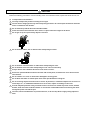
CAUTION
CAUTION rotated
object
CAUTION HOT
Danger Electric shock
risk
Danger explosive
Prohibited
Disassembly is
prohibited
KEEP FIRE AWAY
General instruction
Earth ground
After reading this specifications and instructions manual, store it where the user can access it easily for reference.
The numeric control unit is configured of the control unit, operation board, servo drive unit, spindle drive unit, power
supply, servo motor and spindle motor, etc.
In this section "Precautions for safety", the following items are generically called the "motor".
• Servo motor
• Linear servo motor
• Spindle motor
• Direct-drive motor
In this section "Precautions for safety", the following items are generically called the "unit".
• Servo drive unit
• Spindle drive unit
• Power supply unit
• Scale interface unit
• Magnetic pole detection unit
POINT
Important matters that should be understood for operation of this machine are indicated as a POINT in this
manual.
WARNING
1. Electric shock prevention
Do not open the front cover while the power is ON or during operation. Failure to observe this could lead to
electric shocks.
Do not operate the unit with the front cover removed. The high voltage terminals and charged sections will
be exposed, and can cause electric shocks.
Do not remove the front cover and connector even when the power is OFF unless carrying out wiring work
or periodic inspections. The inside of the units is charged, and can cause electric shocks.
Since the high voltage is supplied to the main circuit connector while the power is ON or during operation,
do not touch the main circuit connector with an adjustment screwdriver or the pen tip. Failure to observe
this could lead to electric shocks.
Wait at least 15 minutes after turning the power OFF, confirm that the CHARGE lamp has gone out, and
check the voltage between P and N terminals with a tester, etc., before starting wiring, maintenance or
inspections. Failure to observe this could lead to electric shocks.
Ground the unit and motor. For the motor, ground it via the drive unit.
Wiring, maintenance and inspection work must be done by a qualified technician.
Wire the servo drive unit and servo motor after installation. Failure to observe this could lead to electric
shocks.
Do not touch the switches with wet hands. Failure to observe this could lead to electric shocks.
Do not damage, apply forcible stress, place heavy items on the cables or get them caught. Failure to
observe this could lead to electric shocks.
After assembling the built-in IPM spindle motor, if the rotor is rotated by hand etc., voltage occurs between
the terminals of lead. Take care not to get electric shocks.
WARNING
2. Injury prevention
When handling a motor, perform operations in safe clothing.
In the system where the optical communication with CNC is executed, do not see directly the light
generated from CN1A/CN1B connector of drive unit or the end of cable. When the light gets into eye, you
may feel something is wrong for eye.
(The light source of optical communication corresponds to class1 defined in JISC6802 or IEC60825-1.)
The linear servo motor, direct-drive motor and built-in IPM spindle motor uses permanent magnets in the
rotor, so observe the following precautions.
(1)Handling
• The linear servo motor, direct-drive motor and built-in IPM spindle motor could adversely affect medical
electronics such as pacemakers, etc., therefore, do not approach the rotor.
• Do not place magnetic materials as iron.
• When a magnetic material as iron is placed, take safety measure not to pinch fingers or hands due to the
magnetic attraction force.
• Remove metal items such as watch, piercing jewelry, necklace, etc.
• Do not place portable items that could malfunction or fail due to the influence of the magnetic force.
• When the rotor is not securely fixed to the machine or device, do not leave it unattended but store it in the
package properly.
(2)Transportation and storage
• Correctly store the rotor in the package to transport and store.
• During transportation and storage, draw people's attention by applying a notice saying "Strong magnetHandle with care" to the package or storage shelf.
• Do not use a damaged package.
(3)Installation
• Take special care not to pinch fingers, etc., when installing (and unpacking) the linear servo motor.
CAUTION
1. Fire prevention
Install the units, motors and regenerative resistor on non-combustible material. Direct installation on
combustible material or near combustible materials could lead to fires.
Always install a circuit protector and contactor on the servo drive unit power input as explained in this
manual. Refer to this manual and select the correct circuit protector and contactor. An incorrect selection
could result in fire.
Shut off the power on the unit side if a fault occurs in the units. Fires could be caused if a large current
continues to flow.
When using a regenerative resistor, provide a sequence that shuts off the power with the regenerative
resistor's error signal. The regenerative resistor could abnormally overheat and cause a fire due to a fault
in the regenerative transistor, etc.
The battery unit could heat up, ignite or rupture if submerged in water, or if the poles are incorrectly wired.
Cut off the main circuit power with the contactor when an alarm or emergency stop occurs.
2. Injury prevention
Do not apply a voltage other than that specified in this manual, on each terminal. Failure to observe this
item could lead to ruptures or damage, etc.
Do not mistake the terminal connections. Failure to observe this item could lead to ruptures or damage,
etc.
Do not mistake the polarity (+,- ). Failure to observe this item could lead to ruptures or damage, etc.
Do not touch the radiation fin on unit back face, regenerative resistor or motor, etc., or place parts (cables,
etc.) while the power is turned ON or immediately after turning the power OFF. These parts may reach high
temperatures, and can cause burns or part damage.
Structure the cooling fan on the unit back face, etc., etc so that it cannot be touched after installation.
Touching the cooling fan during operation could lead to injuries.
Take care not to suck hair, clothes, etc. into the cooling fan.
CAUTION
3. Various precautions
Observe the following precautions. Incorrect handling of the unit could lead to faults, injuries and electric shocks, etc.
(1) Transportation and installation
Correctly transport the product according to its weight.
Use the motor's hanging bolts only when transporting the motor. Do not transport the machine when the
motor is installed on the machine.
Do not stack the products above the tolerable number.
Follow this manual and install the unit or motor in a place where the weight can be borne.
Do not get on top of or place heavy objects on the unit.
Do not hold the cables, axis or detector when transporting the motor.
Do not hold the connected wires or cables when transporting the units.
Do not hold the front cover when transporting the unit. The unit could drop.
Always observe the installation directions of the units or motors.
Secure the specified distance between the units and control panel, or between the servo drive unit and
other devices.
Do not install or run a unit or motor that is damaged or missing parts.
Do not block the intake or exhaust ports of the motor provided with a cooling fan.
Do not let foreign objects enter the units or motors. In particular, if conductive objects such as screws or
metal chips, etc., or combustible materials such as oil enter, rupture or breakage could occur.
Provide adequate protection using a material such as connector for conduit to prevent screws, metallic
detritus, water and other conductive matter or oil and other combustible matter from entering the motor
through the power line lead-out port.
The units, motors and detectors are precision devices, so do not drop them or apply strong impacts to
them.
CAUTION
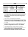
Store and use the units under the following environment conditions.
Environment
Unit
Motor
Ambient temperature
Operation: 0 to 55°C (with no freezing),
Storage / Transportation: -15°C to 70°C
(with no freezing)
Operation: 0 to 40°C (with no freezing),
Storage: -15°C to 70°C (Note2) (with no
freezing)
Ambient humidity
Operation: 90%RH or less
(with no dew condensation)
Storage / Transportation: 90%RH or less
(with no dew condensation)
Operation: 80%RH or less
(with no dew condensation),
Storage: 90%RH or less
(with no dew condensation)
Atmosphere
Altitude
Indoors (no direct sunlight)
With no corrosive gas, inflammable gas, oil mist, dust or conductive fine particles
Operation/Storage:
1000 meters or less above sea level,
Transportation:
13000 meters or less above sea level
Vibration/impact
Operation:
1000 meters or less above sea level,
Storage:
10000 meters or less above sea level
According to each unit or motor specification
(Note 1) For details, confirm each unit or motor specifications in addition.
(Note 2) -15°C to 55°C for linear servo motor.
When disinfectants or insecticides must be used to treat wood packaging materials, always use methods
other than fumigation (for example, apply heat treatment at the minimum wood core temperature of 56 °C
for a minimum duration of 30 minutes (ISPM No. 15 (2009))).
If products such as units are directly fumigated or packed with fumigated wooden materials, halogen
substances (including fluorine, chlorine, bromine and iodine) contained in fumes may contribute to the
erosion of the capacitors.
When exporting the products, make sure to comply with the laws and regulations of each country.
Do not use the products in conjunction with any components that contain halogenated flame retardants
(bromine, etc). Failure to observe this may cause the erosion of the capacitors.
Securely fix the servo motor to the machine. Insufficient fixing could lead to the servo motor slipping off
during operation.
Always install the servo motor with reduction gear in the designated direction. Failure to do so could lead
to oil leaks.
Structure the rotary sections of the motor so that it can never be touched during operation. Install a cover,
etc., on the shaft.
When installing a coupling to a servo motor shaft end, do not apply an impact by hammering, etc. The
detector could be damaged.
Do not apply a load exceeding the tolerable load onto the servo motor shaft. The shaft could break.
Store the motor in the package box.
When inserting the shaft into the built-in IPM spindle motor, do not heat the rotor higher than 130°C. The
magnet could be demagnetized, and the specifications characteristics will not be ensured.
Always use a nonmagnetic tool (explosion-proof beryllium copper alloy safety tool: NGK Insulators, etc.)
when installing the built-in IPM spindle motor, direct-drive motor and linear servo motor.
Always provide a mechanical stopper on the end of the linear servo motor's travel path.
If the unit has been stored for a long time, always check the operation before starting actual operation.
Please contact the Service Center, Service Station, Sales Office or delayer.
CAUTION
(2) Wiring
Correctly and securely perform the wiring. Failure to do so could lead to abnormal operation of the motor.
Do not install a condensing capacitor, surge absorber or radio noise filter on the output side of the drive
unit.
Correctly connect the output side of the drive unit (terminals U, V, W). Failure to do so could lead to
abnormal operation of the motor.
When using a power regenerative power supply unit, always install an AC reactor for each power supply
unit.
In the main circuit power supply side of the unit, always install an appropriate circuit protector or contactor
for each unit. Circuit protector or contactor cannot be shared by several units.
Always connect the motor to the drive unit's output terminals (U, V, W).
Do not directly connect a commercial power supply to the servo motor. Failure to observe this could result
in a fault.
When using an inductive load such as a relay, always connect a diode as a noise measure parallel to the
load.
When using a capacitance load such as a lamp, always connect a protective resistor as a noise measure
serial to the load.
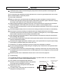
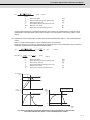
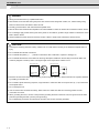
Servo drive unit
Do not reverse the direction of a diode which
COM
connect to a DC relay for the control output
(24VDC)
signals such as contractor and motor brake
output, etc. to suppress a surge. Connecting it
Control output
backwards could cause the drive unit to
signal
malfunction so that signals are not output, and
emergency stop and other safety circuits are inoperable.
Servo drive unit
COM
(24VDC)
RA
Control output
signal
RA
Do not connect/disconnect the cables connected between the units while the power is ON.
Securely tighten the cable connector fixing screw or fixing mechanism. An insecure fixing could cause the
cable to fall off while the power is ON.
When using a shielded cable instructed in the instruction manual, always ground the cable with a cable
clamp, etc.
Always separate the signals wires from the drive wire and power line.
Use wires and cables that have a wire diameter, heat resistance and flexibility that conforms to the system.
(3) Trial operation and adjustment
Check and adjust each program and parameter before starting operation. Failure to do so could lead to
unforeseen operation of the machine.
Do not make remarkable adjustments and changes of parameter as the operation could become unstable.
The usable motor and unit combination is predetermined. Always check the combinations and parameters
before starting trial operation.
The direct-drive motor and linear servo motor do not have a stopping device such as magnetic brakes.
Install a stopping device on the machine side.
When using the linear servo motor for an unbalance axis, adjust the unbalance weight to 0 by installing an
air cylinder, etc. on the machine side. The unbalance weight disables the initial magnetic pole adjustment.
CAUTION
(4)
Usage methods
In abnormal state, install an external emergency stop circuit so that the operation can be stopped and
power shut off immediately.
Turn the power OFF immediately if smoke, abnormal noise or odors are generated from the unit or motor.
Do not disassemble or repair this product.
Never make modifications.
When an alarm occurs, the machine will start suddenly if an alarm reset (RST) is carried out while an
operation start signal (ST) is being input. Always confirm that the operation signal is OFF before carrying
out an alarm reset. Failure to do so could lead to accidents or injuries.
Reduce magnetic damage by installing a noise filter. The electronic devices used near the unit could be
affected by magnetic noise. Install a line noise filter, etc., if there is a risk of magnetic noise.
Use the unit, motor and regenerative resistor with the designated combination. Failure to do so could lead
to fires or trouble.
The brake (magnetic brake) of the servo motor are for holding, and must not be used for normal braking.
There may be cases when holding is not possible due to the magnetic brake's life, the machine
construction (when ball screw and servo motor are coupled via a timing belt, etc.) or the magnetic brake's
failure. Install a stop device to ensure safety on the machine side.
After changing the programs/parameters or after maintenance and inspection, always test the operation
before starting actual operation.
Do not enter the movable range of the machine during automatic operation. Never place body parts near or
touch the spindle during rotation.
Follow the power supply specification conditions given in each specification for the power (input voltage,
input frequency, tolerable sudden power failure time, etc.).
Set all bits to "0" if they are indicated as not used or empty in the explanation on the bits.
Do not use the dynamic brakes except during the emergency stop. Continued use of the dynamic brakes
could result in brake damage.
If a circuit protector for the main circuit power supply is shared by several units, the circuit protector may
not activate when a short-circuit fault occurs in a small capacity unit. This is dangerous, so never share the
circuit protector.
Mitsubishi spindle motor is dedicated to machine tools. Do not use for other purposes.
(5)
Troubleshooting
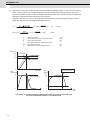
If a hazardous situation is predicted during power failure or product trouble, use a servo motor with
magnetic brakes or install an external brake mechanism.
Use a double circuit configuration that allows the
operation circuit for the magnetic brakes to be operated
even by the external emergency stop signal.
Shut off with the servo motor
brake control output.
EMG
Servo motor
MBR
Always turn the main circuit power of the motor OFF
when an alarm occurs.
If an alarm occurs, remove the cause, and secure the
safety before resetting the alarm.
Shut off with NC brake
control PLC output.
Magnetic
brake
24VDC
CAUTION
(6) Maintenance, inspection and part replacement
Always backup the programs and parameters before starting maintenance or inspections.
The capacity of the electrolytic capacitor will drop over time due to self-discharging, etc. To prevent
secondary disasters due to failures, replacing this part every five years when used under a normal
environment is recommended. Contact the Service Center, Service Station, Sales Office or delayer for
repairs or part replacement.
Do not perform a megger test (insulation resistance measurement) during inspections.
If the battery low warning is issued, immediately replace the battery. Replace the batteries while applying
the drive unit's control power.
Do not short circuit, charge, overheat, incinerate or disassemble the battery.
For after-purchase servicing of the built-in motor, only the servicing parts for MITSUBISHI detector can be
supplied. For the motor body, prepare the spare parts at the machine manufacturers.
For maintenance, part replacement, and services in case of failures in the built-in motor (including the
detector), take necessary actions at the machine manufacturers. For drive unit, Mitsubishi can offer the
after-purchase servicing as with the general drive unit.
(7) Disposal
Take the batteries and backlights for LCD, etc., off from the controller, drive unit and motor, and dispose of
them as general industrial wastes.
Do not disassemble the unit or motor.
Dispose of the battery according to local laws.
Always return the secondary side (magnet side) of the linear servo motor to the Service Center or Service
Station.
When incinerating optical communication cable, hydrogen fluoride gas or hydrogen chloride gas which is
corrosive and harmful may be generated. For disposal of optical communication cable, request for
specialized industrial waste disposal services that has incineration facility for disposing hydrogen fluoride
gas or hydrogen chloride gas.
(8) Transportation
The unit and motor are precision parts and must be handled carefully.
According to a United Nations Advisory, the battery unit and battery must be transported according to the
rules set forth by the International Civil Aviation Organization (ICAO), International Air Transportation
Association (IATA), International Maritime Organization (IMO), and United States Department of
Transportation (DOT), etc.
(9) General precautions
The drawings given in this manual show the covers and safety partitions, etc., removed to provide a clearer
explanation. Always return the covers or partitions to their respective places before starting operation, and
always follow the instructions given in this manual.
Treatment of waste
The following two laws will apply when disposing of this product. Considerations must be made to each law.
The following laws are in effect in Japan. Thus, when using this product overseas, the local laws will have a
priority. If necessary, indicate or notify these laws to the final user of the product.
(1) Requirements for "Law for Promotion of Effective Utilization of Resources"
(a) Recycle as much of this product as possible when finished with use.
(b) When recycling, often parts are sorted into steel scraps and electric parts, etc., and sold to scrap
contractors. Mitsubishi recommends sorting the product and selling the members to appropriate
contractors.
(2) Requirements for "Law for Treatment of Waste and Cleaning"
(a) Mitsubishi recommends recycling and selling the product when no longer needed according to item
(1) above. The user should make an effort to reduce waste in this manner.
(b) When disposing a product that cannot be resold, it shall be treated as a waste product.
(c) The treatment of industrial waste must be commissioned to a licensed industrial waste treatment
contractor, and appropriate measures, including a manifest control, must be taken.
(d) Batteries correspond to "primary batteries", and must be disposed of according to local disposal
laws.
Disposal
(Note)
This symbol mark is for EU countries only.
This symbol mark is according to the directive 2006/66/EC Article 20 Information for endusers and Annex II.
Your MITSUBISHI ELECTRIC product is designed and manufactured with high quality materials and
components which can be recycled and/or reused.
This symbol means that batteries and accumulators, at their end-of-life, should be disposed of
separately from your household waste.
If a chemical symbol is printed beneath the symbol shown above, this chemical symbol means that the
battery or accumulator contains a heavy metal at a certain concentration. This will be indicated as
follows:
Hg: mercury (0,0005%), Cd: cadmium (0,002%), Pb: lead (0,004%)
In the European Union there are separate collection systems for used batteries and accumulators.
Please, dispose of batteries and accumulators correctly at your local community waste collection/
recycling centre.
Please, help us to conserve the environment we live in!
Trademarks
MELDAS, MELSEC, EZSocket, EZMotion, iQ Platform, MELSOFT, GOT, CC-Link, CC-Link/LT and CC-Link
IE are either trademarks or registered trademarks of Mitsubishi Electric Corporation in Japan and/or other
countries.
Other company and product names that appear in this manual are trademarks or registered trademarks of the
respective companies.
本製品の取扱いについて
( 日本語 /Japanese)
本製品は工業用 ( クラス A) 電磁環境適合機器です。販売者あるいは使用者はこの点に注意し、住商業環境以外で
の使用をお願いいたします。
Handling of our product
(English)
This is a class A product. In a domestic environment this product may cause radio interference in which case the
user may be required to take adequate measures.
본 제품의 취급에 대해서
( 한국어 /Korean)
이 기기는 업무용 (A 급 ) 전자파적합기기로서 판매자 또는 사용자는 이 점을 주의하시기 바라며 가정외의 지역에
서 사용하는 것을 목적으로 합니다 .
WARRANTY
Please confirm the following product warranty details before using MITSUBISHI CNC.
1. Warranty Period and Coverage
Should any fault or defect (hereafter called "failure") for which we are liable occur in this product during the warranty period,
we shall provide repair services at no cost through the distributor from which the product was purchased or through a
Mitsubishi Electric service provider. Note, however that this shall not apply if the customer was informed prior to purchase of
the product that the product is not covered under warranty. Also note that we are not responsible for any on-site readjustment
and/or trial run that may be required after a defective unit is replaced.
[Warranty Term]
The term of warranty for this product shall be twenty-four (24) months from the date of delivery of product to the end user,
provided the product purchased from us in Japan is installed in Japan (but in no event longer than thirty (30) months,
Including the distribution time after shipment from Mitsubishi Electric or its distributor).
Note that, for the case where the product purchased from us in or outside Japan is exported and installed in any country
other than where it was purchased; please refer to "2. Service in overseas countries" as will be explained.
[Limitations]
(1) The customer is requested to conduct an initial failure diagnosis by him/herself, as a general rule. It can also be carried
out by us or our service provider upon the customer’s request and the actual cost will be charged.
(2) This warranty applies only when the conditions, method, environment, etc., of use are in compliance with the terms and
conditions and instructions that are set forth in the instruction manual, user’s manual, and the caution label affixed to the
product, etc.
(3) Even during the term of warranty, repair costs shall be charged to the customer in the following cases:
(a) a failure caused by improper storage or handling, carelessness or negligence, etc., or a failure caused by the
customer’s hardware or software problem
(b) a failure caused by any alteration, etc., to the product made by the customer without Mitsubishi Electric’s approval
(c) a failure which may be regarded as avoidable, if the customer’s equipment in which this product is incorporated is
equipped with a safety device required by applicable laws or has any function or structure considered to be
indispensable in the light of common sense in the industry
(d) a failure which may be regarded as avoidable if consumable parts designated in the instruction manual, etc. are duly
maintained and replaced
(e) any replacement of consumable parts (including a battery, relay and fuse)
(f) a failure caused by external factors such as inevitable accidents, including without limitation fire and abnormal
fluctuation of voltage, and acts of God, including without limitation earthquake, lightning, and natural disasters
(g) a failure which is unforeseeable under technologies available at the time of shipment of this product from our company
(h) any other failures which we are not responsible for or which the customer acknowledges we are not responsible for
2. Service in Overseas Countries
If the customer installs the product purchased from us in his/her machine or equipment, and export it to any country other
than where he/she bought it, the customer may sign a paid warranty contract with our local FA center.
This falls under the case where the product purchased from us in or outside Japan is exported and installed in any country
other than where it was purchased.
For details please contact the distributor from which the customer purchased the product.
3. Exclusion of Responsibility for Compensation against Loss of Opportunity, Secondary Loss, etc.
Whether during or after the term of warranty, we assume no responsibility for any damages arising from causes for which we
are not responsible, any losses of opportunity and/or profit incurred by the customer due to a failure of this product, any
damages, secondary damages or compensation for accidents arising under specific circumstances that either foreseen or
unforeseen by Mitsubishi Electric, any damages to products other than this product, or compensation for any replacement
work, readjustment and startup test run of on-site machines or any other operations conducted by the customer.
4. Changes in Product Specifications
Specifications shown in our catalogs, manuals or technical documents are subject to change without notice.
5. Product Application
(1) For the use of this product, its applications should be those that may not result in a serious damage even if any failure or
malfunction occurs in the product, and a backup or fail-safe function should operate on an external system to the product
when any failure or malfunction occurs.
(2) Mitsubishi CNC is designed and manufactured solely for applications to machine tools to be used for industrial purposes.
Do not use this product in any applications other than those specified above, especially those which are substantially
influential on the public interest or which are expected to have significant influence on human lives or properties.
Precautions of how to Handle Linear Motors
This section is on storage, installation, maintenance and disposal. Incorrect handling may lead to unforeseen accidents,
so ensure correct usage according to the description in this section.
Even if not mentioned in this section, there may be a situation that may be dangerous. In such a situation, please take a
measure to prevent the danger.
WARNING
1. All the processes as storage, installation, maintenance and disposal must be done by a qualified technician.
2. As the product has permanent magnets, not only motor operators but also machine or device operators must take
special care in handling. Pay attention so that a person with a medical device such as pacemaker won't approach the
product.
3. Do not place magnetic material such as iron close to the product.
4. Before handling, remove metal items such as watch, piercing jewelry, necklace, etc.
5. In installing the product and peripheral structures, make sure to use nonmagnetic tools (Explosion-proof beryllium copper
alloy safety tool: Nihon Gaishi, etc).
6.Do not leave the product (primary and secondary side) unattended.
→When they are not fixed to the machine or device, make sure to store them in the package.
7. Immediately stop using the product if any abnormality is found about the product.
CAUTION
1. Do not arrange the product, or do not give a shock.
2. Do not get on top of or place heavy objects on the product.
3. Correctly and securely perform the wiring.
→Especially, fix the terminals or connectors of the power cables firmly enough.
4. Perform the wiring after installing the product to the machine and device.
5. Environment in transportation, storage and usage must follow the specified conditions.
Precautions of how to Handle Linear Motors
1 Production Outline
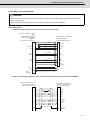
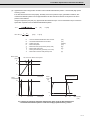
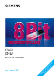
1.1 Structure of Liner Servo Motor
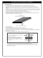
Our linear servo motor consists mainly of the primary side (LM-FP) with cores and coils, and the secondary side (LM-FS)
with yoke and permanent magnets.
As the secondary side has permanent magnets, take special care in handling.
Cooling pipe
Metal cover
Laminated core
Molded resin
Motor coil
Permanent
magnet
Mounting plate (yoke)
Fig. 1 Structure of linear servo motor
1.2 Primary Side
The primary side has motor cores to which windings are applied. The cores are protected by mold.
Compared with metal parts, the mold is susceptible to breaking or cracking due to shock or stress, which may deteriorate
the product's quality.
Therefore, pay special attention in carrying and installing not to damage the mold.
Precautions of how to Handle Linear Motors
1.3 Secondary Side
The secondary side has a yoke with permanent magnets on. The mold is applied to the surface of it.
As it has permanent magnets, magnetic attraction force is generated between it and magnetic material as iron.
The magnetic attraction force is generated mainly on the magnet side. (Almost no attraction force is generated on the
yoke side.)
The linear servo motor uses an extremely powerful magnet, so if the motor is attracted on the metal surface or magnets
are attracted to each other, an attraction force of maximum t is generated, and possibly resulting in serious bodily injury.
Once attached, they cannot be separated without destruction of the product.
Therefore, take safety measure in handling to avoid accidents due to the attraction force.
In addition, the magnetic force is released into the air, so do not make devices that are affected by the magnetic force
such as pacemaker, watch, etc. approach to the product.
Magnet side
(Magnetic attraction force generated)
Yoke side
(Almost no attraction force generated)
<Permanent magnet>
Permanent magnet releases the magnetic force into the air all the time.
So the magnetic attraction force is generated if magnetic material is placed close to the magnet.
In addition, as the magnetic force is released into the air, devices susceptible to the magnetic force may be damaged if
they are placed near the product.
As our linear servo motor has high quality magnets, take special care in handling.
Magnetic force
The size of the magnetic attraction force is about 4 [kgf/
cm2] between a magnet and iron.
↓
However, when an iron plate completely attaches to
LM-FS50-480, the attraction force size is about
20cm × 48cm × 4kgf/cm2 = 3840kgf, so they cannot be
separated easily.
N
S
Especially if two secondary sides are placed close to each other, it is highly dangerous as the magnetic attraction
force will be greatly strong. For the secondary side, take the sufficient safety measure.
If more than one secondary side are used together, or when you exchange secondary sides, never leave the
secondary sides unattended.
Precautions of how to Handle Linear Motors
2 Transportation/Storage
WARNING
1. Correctly store the linear servo motor in the package to transport and store.
→As the secondary side has permanent magnets in it, and the magnetic attraction force is generated between magnetic
material as iron, unexpected accidents or failures may occur if the secondary side is left unattended.
2. During transportation and storage, draw people's attention by applying a notice saying "Strong magnet-Handle with care"
to the package or storage shelf.
CAUTION
1. Follow the conditions below in transportation and storage.
Storage temperature : -15°C to +50°C (with no freezing)
Storage humidity : 90%RH or less (with no dew condensation)
Atmosphere :
- Indoors (where the product is not subject to direct sunlight)
- No corrosive gas, combustible gas or dust
- No oil or water splash
Vibration : 5G or less
2. Do not arrange the product, or do not give a shock.
3. Do not get on top of or place heavy objects on the product.
4. When suspending the product with lifting sling, etc, do not give a shock or stress to the mold.
5. If the product has been stored for a long time, please contact your local service center or service station.
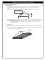
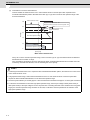
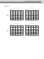
POINT
The secondary side's package structure is as in the figure below. The structure avoids dangers caused by the magnetic
attraction force released outside the package.
Product
Cushioning
Package
Precautions of how to Handle Linear Motors
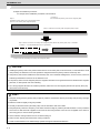
2.1 How to Suspend the Product
(1)
Primary side (coil)
Before you suspend the primary side (coil) alone, attach eye bolts, etc. to the fixing screw holes for a slider.
Please ensure that the wires put no stress on the lead wire, connector or cooling vent when suspending the
product.
When suspending the product, support it at the both ends in the lengthwise direction (two or more points).
Attach eye bolts to the fixing
screw holes.
We recommend that you attach the primary side (coil) to the slider and then attach the hanging tools to the slider
before suspending the primary side.
(Note)
General sliders have larger dimensions than the primary side (coil), therefore the sliders can protect itself
mechanically. But they may obscure the product's peripheral area from view, therefore you have to
prepare wider working area.
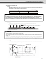
(2)
Secondary side
Before you suspend the secondary side, attach the hanging tools such as eye bolts to the screw holes for hanging
tool.
In order to avoid any risks posed by the magnetic attraction force, always place the secondary side with its magnet
side up. Support it at four points to keep this posture.
Magnet side
(Always set this side up)
Precautions of how to Handle Linear Motors
3 Installation
WARNING
1. Installation must be done by a qualified technician.
2. Pay attention so that a person with a medical device such as pacemaker won't approach the product. The device may be
affected by the permanent magnets.
3. Do not place magnetic material such as iron close to the product.
4. Before installing, remove metal items such as watch, piercing jewelry, necklace, etc.
5. In installing the product and peripheral structures, make sure to use nonmagnetic tools (Explosion-proof beryllium copper
alloy safety tool: Nihon Gaishi, etc).
6. Do not leave the permanent magnet of secondary side unattended after taking it out from the package. Pay special
attention not to approach the permanent magnet except a worker during installation.
7. Immediately stop using the product if any abnormality is found about the product.
8. Perform the installation correctly following the example in this manual.
9. When multiple operators are engaged in the operation, confirm that no operator is within the range of motion before
energizing the product. If any operator remains in the range of motion, take measures to prevent the motion with
interlock system, etc.
10. When using the linear servo motor for an unbalance axis, adjust the unbalance weight to 0 by installing an air cylinder,
etc. on the machine side. The unbalance weight disables the initial magnetic pole adjustment.
CAUTION
1. Do not arrange the product, or do not give a shock.
2. Do not get on top of or place heavy objects on the product.
3. Correctly and securely perform the wiring.
→ Especially, fix the terminals or connectors of the power cables firmly enough.
4. Perform the wiring after installing the product to the machine and device.
5. If iron chips, etc. adhere to the product during installation, completely remove them.
6. Do not install with wet hands.
7. Perform the installation following the conditions below.
Ambient temperature : 0°C to +40°C (With no freezing)
Ambient humidity : 80%RH or less (With no dew condensation)
Atmosphere :
- Indoors (where the product is not subject to direct sunlight)
- No corrosive gas, combustible gas or dust
- No oil or water splash
Vibration : 5G or less
Altitude : 1000m or less
Precautions of how to Handle Linear Motors
4 Maintenance/Inspection
WARNING
1. Maintenance, inspection or parts replacement must be done by a qualified technician.
2. Pay attention so that a person with a medical device such as pacemaker won't approach the product. The device may
be affected by the permanent magnets.
3. Make sure to turn OFF the power before starting maintenance, inspection and parts replacement.
4. Do not place magnetic material such as iron close to the product.
5. Before starting maintenance, inspection or parts replacement, remove metal items such as watch, piercing jewelry,
necklace, etc.
6. In installing the product and peripheral structures, make sure to use nonmagnetic tools (Explosion-proof beryllium
copper alloy safety tool: Nihon Gaishi, etc).
7. Do not leave the product (primary and secondary side) unattended.
→Particularly when you replace the secondary sides, observe the following sequence strictly:
first, store the detached product in the package, take the secondary side to be replaced, and then attach it.
If there are any magnetic substances around, take safety measures in order to avoid any risks posed by the magnetic
attraction force of the secondary side.
8. When multiple operators are engaged in the operation, confirm that no operator is within the range of motion before
energizing the product. If any operator remains in the range of motion, take measures to prevent the motion with
interlock system, etc
Precautions of how to Handle Linear Motors
CAUTION
1. Do not arrange the product, or do not give a shock.
2. Do not get on top of or place heavy objects on the product.
3. Correctly and securely perform the wiring.
→Particularly, fix the terminals or connectors of the power cables firmly enough.
4. The accessory cables (both power cable and thermal cable) have a hard-wired specification. Therefore fix them firmly
enough to a motor or equipment.
5. Perform the wiring after installing the product to the machine and device.
6. If iron chips, etc. adhere to the product during installation, completely remove them.
7. Do not work with wet hands.
8. Perform the operation following the conditions below.
Ambient temperature : 0°C to +40°C (with no freezing)
Ambient humidity : 80%RH or less (with no dew condensation)
Atmosphere :
- Indoor (where the product is not subject to direct sunlight.)
- No corrosive gas, flammable gas or dust.
- No oil or water splash
Vibration : 5G or less
Altitude : 1000m or less
Precautions of how to Handle Linear Motors
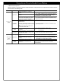
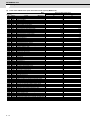
< Maintenance/Inspection >
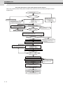
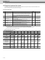
Periodic inspection is required so that the unexpected failures can be prevented. The inspection items and the remedies
are described in the following table.
Location
Item
Appearance
Primary side
(Coil)
Insulation
resistance
Loosened
screw
Lead wire
Connector
Secondary
side
(Magnet)
Appearance
Detail
- Confirm that there are no cracks or
breaks.
- Confirm that there are no traces of
rubbing.
- Confirm that no water or oil remains.
→ Continuous wet condition may cause
considerable insulation degradation.
- Measure the insulation resistance with a
megger tester.
<Specified value>
Room temp. (about 20°C) : 100MΩ or more
High temp. (just after operation) : 10MΩ or
more
These are the values of Coil-GND, CoilThermal and Thermal-GND.
- Confirm that no fixing screws are
loosened.
- Confirm that there is no abnormality such
as discoloration, cracks or breaks of the
lead wire or connector.
- Confirm that there are no cracks or
breaks.
- Confirm that there are no traces of
rubbing.
- Confirm that no water or oil remains.
Loosened
screw
- Confirm that no fixing screws are
loosened.
Remedy for errors
- If any cracks or breaks are found, replace the product.
- If any traces of rubbing are found, remove the causes of
rubbing. Replace the product in case that rubbing is
considerable, or it causes cracks or breaks.
- If it is severely wet, enhance the water and oil resistance.
- If the insulation resistance is below the specified value,
replace the product.
- If the insulation resistance is below the specified value,
replace the product.
- If any screws are loosening, tighten them.
(Note) Replacing bolts at the time of inspection is
recommended.
- If there is any abnormality, replace the product.
- If any cracks or breaks are found, replace the product.
- If any traces of rubbing are found, remove the causes of
rubbing. Replace the product in case that rubbing is
considerable, or it causes cracks or breaks.
- If it is severely wet, enhance the water and oil resistance.
- If any screws are loosening, tighten them.
(Note) Replacing bolts at the time of inspection is
recommended.
Precautions of how to Handle Linear Motors
5 Disposal
WARNING
1. Disposal work must be done by a qualified technician.
2. Do not place the devices such as pacemakers and watches near the product. The magnetic force of the permanent
magnet may cause damage or malfunction of those devices.
3. Do not place the magnetic substance (e.g. iron) near the product.
4. Put off the metal products such as watch, pierce and necklace before disposing of the product.
5. Use nonmagnetic tools (Explosion-proof beryllium copper alloy safety tool: Nihon Gaishi, etc) when disposing of the
product.
6. Do not leave the product (primary side or secondary side) alone.
7. Dispose of the motor primary side as general industrial waste.
8. After demagnetizing the motor secondary side with the heat of over 300°C, dispose of it as general industrial waste.
9. If demagnetization is not possible, please return the product to Mitsubishi Electric.
→In such a case, return the motor after storing it in the package.
Contents
1 Introduction ............................................................................................................................................ 1 - 1
1.1 Drive System Configuration .............................................................................................................. 1 - 2
1.1.1 System Configuration................................................................................................................ 1 - 2
1.2 Explanation of Type .......................................................................................................................... 1 - 4
1.2.1 Linear Servo Motor Type .......................................................................................................... 1 - 4
2 Specifications......................................................................................................................................... 2 - 1
2.1 Linear Servo Motor ........................................................................................................................... 2 - 2
2.1.1 Specifications List ..................................................................................................................... 2 - 2
2.1.2 Thrust Characteristics ............................................................................................................... 2 - 4
2.1.3 Liquid Cooling Specification...................................................................................................... 2 - 5
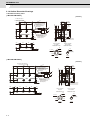
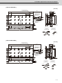
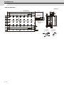
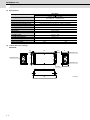
2.1.4 Outline Dimension Drawings..................................................................................................... 2 - 6
3 Characteristics ....................................................................................................................................... 3 - 1
3.1 Linear Servo Motor ........................................................................................................................... 3 - 2
3.1.1 Overload Protection Characteristics ......................................................................................... 3 - 2
3.1.2 Dynamic Brake Characteristics ................................................................................................ 3 - 6
4 Dedicated Options ................................................................................................................................. 4 - 1
4.1 Linear Servo Detectors ..................................................................................................................... 4 - 2
4.1.1 Absolute Position Detector........................................................................................................ 4 - 2
4.1.2 Relative Position Detector......................................................................................................... 4 - 3
4.2 Detector Interface Unit ...................................................................................................................... 4 - 5
4.2.1 Serial Output Interface Unit for ABZ Analog Detector MDS-B-HR............................................ 4 - 5
4.2.2 Serial Output Interface Unit for ABZ Analog Detector EIB192M
(Other Manufacturer's Product) ................................................................................................ 4 - 8
4.2.3 Serial Output Interface Unit for ABZ Analog Detector EIB392M
(Other Manufacturer's Product) ................................................................................................ 4 - 9
4.3 Pole Detection Unit (MDS-B-MD) ................................................................................................... 4 - 10
4.4 Cables and Connectors .................................................................................................................. 4 - 12
4.4.1 Cable Connection Diagram..................................................................................................... 4 - 12
4.4.2 Example of the Detector Conversion Unit Connection............................................................ 4 - 14
4.4.3 List of Cables and Connectors................................................................................................ 4 - 15
4.4.4 Cable Connection Diagram..................................................................................................... 4 - 17
4.4.5 Connector Outline Dimension Drawings ................................................................................. 4 - 19
5 Selection ................................................................................................................................................. 5 - 1
5.1 Selection of the Linear Servo Motor.................................................................................................. 5 - 2
5.1.1 Max. Feedrate........................................................................................................................... 5 - 2
5.1.2 Selection of Linear Servo Motor Capacity................................................................................. 5 - 2
5.1.3 Continuous Thrust..................................................................................................................... 5 - 7
5.2 Selection of the Power Supply Unit (Only MDS-D2/DH2) ................................................................. 5 - 8
5.2.1 Calculation of Linear Motor ....................................................................................................... 5 - 8
5.3 Selection of the Regenerative Resistor (Only MDS-DJ) ................................................................. 5 - 10
5.3.1 Calculation of the Regenerative Energy ................................................................................. 5 - 10
5.3.2 Calculation of the Positioning Frequency................................................................................ 5 - 11
6 Installation .............................................................................................................................................. 6 - 1
6.1 Installation of the Linear Servo Motor ............................................................................................... 6 - 3
6.1.1 Environmental Conditions ......................................................................................................... 6 - 4
6.1.2 Quakeproof Level...................................................................................................................... 6 - 4
6.1.3 Installing the Linear Servo Motor .............................................................................................. 6 - 5
6.1.4 Cooling of Linear Servo Motor .................................................................................................. 6 - 8
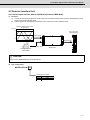
7 Wiring and Connection.......................................................................................................................... 7 - 1
7.1 Part System Connection Diagram..................................................................................................... 7 - 3
7.2 Motor and Detector Connection ........................................................................................................ 7 - 5
7.2.1 Linear Motor Connection........................................................................................................... 7 - 5
8 Setup ....................................................................................................................................................... 8 - 1
8.1 Setting the Initial Parameters for the Linear Motor ........................................................................... 8 - 2
8.1.1 Setting of Detector Related Parameters ................................................................................... 8 - 2
8.1.2 List of Standard Parameters for Each Linear Motor.................................................................. 8 - 4
8.2 Initial Setup for the Absolute Position Detection System ................................................................ 8 - 12
8.2.1 Adjustment Procedure ............................................................................................................ 8 - 12
8.2.2 Related parameters ................................................................................................................ 8 - 15
8.3 Initial Setup for Relative Position Detection System ....................................................................... 8 - 16
8.3.1 Adjustment procedure............................................................................................................. 8 - 16
8.3.2 Related parameters ................................................................................................................ 8 - 19
8.4 Protective functions list of units....................................................................................................... 8 - 20
8.4.1 Drive unit alarm....................................................................................................................... 8 - 20
8.4.2 Drive unit warning ................................................................................................................... 8 - 21
8.4.3 Parameter numbers during initial parameter error .................................................................. 8 - 22
9 Servo Adjustment .................................................................................................................................. 9 - 1
9.1 Gain Adjustment................................................................................................................................ 9 - 2
9.1.1 Speed Loop Gain ...................................................................................................................... 9 - 2
1
Introduction
1-1
MITSUBISHI CNC
1 Introduction
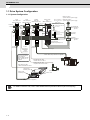
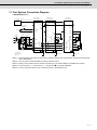
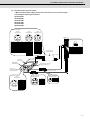
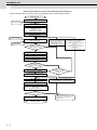
1.1 Drive System Configuration
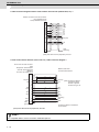
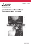
1.1.1 System Configuration
1-axis
servo drive unit
(MDS-D2/DH2-V1)
Spindle
2-axis
drive unit
servo drive unit
(MDS-D2/DH2-V2) (MDS-D2/DH2-SP)
Power supply
unit
(MDS-D2/DH2-CV)
< Built in cell battery >
Battery cable
From NC
Power supply
communication
cable
CN2
Optical
communication
cable
Optical
communication
cable
Cell battery built in drive unit
(ER6V-C119B)
CN4
CN24
CN2
CN2L
CN3L
For external
emergency
stop
CN2M
CN3M
Built in cell battery
for servo drive unit
or
option battery
MDS-D2 Series:
3-phase 200VAC power supply
MDS-DH2 Series:
3-phase 400VAC power supply
<Option battery>
Battery case
(MDS-BTCASE+A6BAT)
CN3
CN23
Battery unit
(MDS-BTBOX-36)
L+
L-
Circuit protector or
protection fuse
(Note) Prepared by user.
Power
connector
To 2nd
axis servo
Circuit protector
(Note) Prepared
by user.
AC reactor
(D/DH-AL)
Contactor
(Note) Prepared
by user.
Power
connector
Contactor control output
To 3rd
axis servo
The circuit of external
power supply or
dynamic brake unit (for
large capacity), etc is
required.
Servo detector cable
< Motor side detector cable >
Power cable (Only connector is supplied.)
Spindle detector cable
< Motor side PLG cable >
Spindle detector cable
< Spindle side detector cable >
Linear motor
Praimary side
Linear motor
Secondary side
Spindle motor
Spindle side detector
Linear scale
Power cable (Only connector is supplied.)
For details on the drive units, refer to “MDS-D2/DH2 Series Specifications Manual” (IB-1501124(ENG)).
1-2
Linear Motor Specifications and Instruction Manual
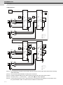
1.1 Drive System Configuration
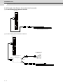
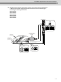
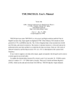
< MDS-DJ Series >
3-phase
200 to 230VAC
L1
L2
L3
Circuit
protector
or
fuse
Circuit protector
(Note)
Prepared by user
Circuit
protector
or
fuse
Circuit protector
(Note)
Prepared by user
Circuit
protector
or
fuse
Circuit protector
(Note)
Prepared by user
Circuit
protector
or
fuse
Circuit protector
(Note)
Prepared by user
(Note)
Prepared
by user
Contactor
(Note)
Prepared by user
(Note)
Prepared
by user
Contactor
(Note)
Prepared by user
(Note)
Prepared
by user
Contactor
(Note)
Prepared by user
(Note)
Prepared
by user
Contactor
(Note)
Prepared by user
Servo
drive unit
(MDS-DJ-V1)
Option
Option
Spindle
drive unit
(MDS-DJ-SP)
Servo
drive unit
(MDS-DJ-V2)
L1 L2 L3
Spindle
drive unit
(MDS-DJ-SP2)
L1 L2 L3
㪚
㪥
㪌
L21
From NC
L21
CN1B
U V W
CN2
㪚
㪥
㪏
㪬
㪭
㪬
㪭
CN1B
㪚
㪥
㪈
㪙
㪚
㪥
㪋
L11
C
L21
㪚
㪥
㪉
㪘
㪚
㪥
㪉
㪙
CN2L
To 2nd
axis servo
CN1A
L21
CN1B
U V W
CN2
CN2M
㪚
㪥
㪊
㪣㪊
㪚
㪥
㪏
CN1A
㪚
㪥
㪈
㪘
㪬
㪭
㪬
㪭
㪚
㪥
㪈
㪙
CN2L
㪚
㪥
㪉
㪘
㪚
㪥
㪉
㪙
㪚
㪥
㪋
CN2M
CN3
To 3rd
axis servo
To 5th
axis spindle
To servo detector
To 6th
axis spindle
To spindle detector
(Note) As for 2-axis drive unit, machine side
detector connection is not available.
Servo detector cable
< Motor side detector cable >
㪣㪈
㪣㪉
U V W
U V W
BAT
BAT
L11
P
CN1A
㪚
㪥
㪈
㪘
CNP1
Regenerative
resistor
CNP1
㪣㪊
U V W
U V W
Regenerative
resistor
㪚
㪥
㪊
CNP3M CNP3L CNP2
C
CN1A
CNP3 CNP2
L11
CNP1
L11
P
㪚
㪥
㪌
L1 L2 L3
㪣㪈
㪣㪉
CNP3M CNP3L CNP2
CNP1
Regenerative
resistor
CNP3 CNP2
L1 L2 L3
Regenerative
resistor
(Note) As for 2-axis drive unit, machine side
detector connection is not available.
Linear motor
Praimary side
Linear motor
Secondary side
Linear scale
Power cable (Only connector is supplied.)
Spindle motor
Spindle side detector
For details on the drive units, refer to "MDS-DJ Series Specifications Manual" (IB-1501130(ENG)).
1-3
MITSUBISHI CNC
1 Introduction
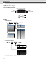
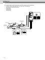
1.2 Explanation of Type
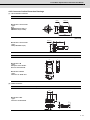
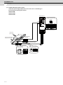
1.2.1 Linear Servo Motor Type
㧨Linear servo motor (Primary side)㧪
LINEAR MOTOR
Type
Rated thrust
Rated current
Serial No.
LM-FP2B-06M-1WW0
600
N
7.8
A
SERIAL xxxxxxxxx
Voltage
Maximum speed
Heat-resistant class
Date of manufacture
200
V
2.0
m/s
F
class
DATE xxxx-xx
MITSUBISHI ELECTRIC CORPORATION, JAPAN
㧨Linear servo motor (Secondary side)㧪
TYPE
LM-FS20-480-1WW0
Type
21204-01
SERIAL NO.
B12345678
21204-01
Nameplate
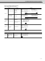
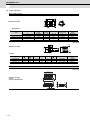
LM-F Series
< Primary side: Coil >
LM - FP (1)
(2)
-
(2) Length
Symbol
Length
A
170mm
B
290mm
D
530mm
(3)
M - 1WW0
Maximum speed
Symbol Maximum speed
M
2.0m/s
(3) Rated thrust
F
770mm
Symbol
Rated thrust
H
1010mm
03
300N
06
600N
(1) Width
12
1200N
Symbol
Width
18
1800N
2
120mm
24
2400N
4
200mm
36
3600N
5
240mm
48
4800N
60
6000N
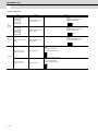
< Secondary side: Magnet >
LM - FS
(1) 0 - (2)
- 1WW0
(2) Length
Symbol
384
480
576
Length
384mm
480mm
576mm
(1) Width
Symbol
Width
2
120mm
4
200mm
5
240mm
(Note) The linear dimension of 384mm is available for LM-FS20 only.
1-4
Serial No.
2
Specifications
2-1
MITSUBISHI CNC
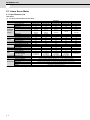
2 Specifications
2.1 Linear Servo Motor
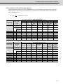
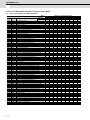
2.1.1 Specifications List
LM-F Series
(1) For drive with standard unit and motor
Type
Linear servo motor type
Primary side type
Secondary side type
MDS-D2-V1MDS-DH2-V1-
Compatible
servo drive
unit type
MDS-D2-V2-
MDS-D2-V3MDS-DJ-V1Power facility capacity [kVA]
Rated (natural-cooling) [Arms]
Current
Rated (liquid-cooling) [Arms]
Maximum [Arms]
Cooling method
Rated (natural-cooling) [N]
Thrust
Rated (liquid-cooling) [N]
Maximum [N]
Maximum speed [m/s] (Note)
Magnetic attraction force [N]
Primary side [kg]
Mass
Secondary side [kg]
Recommended load mass ratio
Structure
Ambient temperature
Environment
Ambient humidity
Atmosphere
Vibration
Altitude
(Note)
2-2
LM-FP2A-03M
LM-FP2A-03M
LM-FP2B-06M
LM-FP2B-06M
LM-FS20- □
40
4020 (L)
4040
8040 (M)
404040
40
2.0
3.5
6.9
26.1
LM-FS20- □
40
4020 (L)
4040
8040 (M)
404040
40
3.5
3.9
7.8
28.1
150
300
900
2500
5
5.8 (384mm)
7.1 (480mm)
9.0 (576mm)
LM-F Series
LM-FP2D-12M
LM-FP2D-12M
LM-FP2F-18M
LM-FP2F-18M
LM-FS20- □
LM-FS20- □
80
160
8040 (L)
16080 (L)
8080
160160
16080 (M)
80
5.5
10
7.7
11.9
15.3
23.2
57.8
84.7
Natural-cooling, liquid-cooling
300
600
900
600
1200
1800
1800
3600
5400
2.0
4500
9000
13500
9
18
27
5.8 (384mm)
5.8 (384mm)
5.8 (384mm)
7.1 (480mm)
7.1 (480mm)
7.1 (480mm)
9.0 (576mm)
9.0 (576mm)
9.0 (576mm)
15 times linear servo motor primary side mass maximum
Open (Degree of protection IP00)
LM-FP4B-12M
LM-FP4B-12M
LM-FS40- □
80
8040 (L)
8080
16080 (M)
80
7.5
7.5
15.7
55.7
600
1200
3600
9000
14
13.5 (480mm)
16.0 (576mm)
0 to 40°C (with no freezing), Storage: -15°C to 55°C (with no freezing)
80%RH or less (with no dew condensation), Storage: 90%RH or less (with no dew condensation)
Indoors (no direct sunlight); no corrosive gas, inflammable gas, oil mist, or dust
49m/s 2 or less
1000 meters or less above sea level
The above value may be limited by the maximum speed of the linear scale.
Linear Motor Specifications and Instruction Manual
2.1 Linear Servo Motor
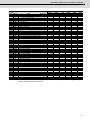
Type
Linear servo motor type
Primary side type
LM-FS40- □
160
16080 (L)
160160
18
14.1
28.6
101.9
Secondary side type
Compatible
servo drive
unit type
MDS-D2-V1MDS-DH2-V1MDS-D2-V2-
Power facility capacity [kVA]
Rated (natural-cooling) [Arms]
Current
Rated (liquid-cooling) [Arms]
Maximum [Arms]
Cooling method
Rated (natural-cooling) [N]
Thrust
Rated (liquid-cooling) [N]
Maximum [N]
Maximum speed [m/s] (Note 1)
Magnetic attraction force [N]
Primary side [kg]
Mass
Secondary side [kg]
1200
2400
7200
18000
28
13.5 (480mm)
16.0 (576mm)
Recommended load mass ratio
Structure
Ambient temperature
Environment
LM-F Series
LM-FP4F-36M
LM-FP4H-48M
LM-FP4F-36M
LM-FP4H-48M
LM-FP4D-24M
LM-FP4D-24M
LM-FP5H-60M
LM-FP5H-60M
LM-FS40- □
320
-
LM-FS40- □
320
-
LM-FS50- □
200 (Note 2)
-
-
-
18
18
24.7
33.6
49.2
65.8
174.9
237.4
Natural-cooling, liquid-cooling
1800
2400
3600
4800
10800
14400
2.0
27000
36000
42
56
13.5 (480mm)
13.5 (480mm)
16.0 (576mm)
16.0 (576mm)
15 times linear servo motor primary side mass maximum
Open (Degree of protection IP00)
22
21.1
42.2
142.0
3000
6000
18000
45000
67
20.0 (480mm)
26.0 (576mm)
0 to 40°C (with no freezing), Storage: -15°C to 55°C (with no freezing)
80%RH or less (with no dew condensation), Storage: 90%RH or less (with no dew condensation)
Indoors (no direct sunlight); no corrosive gas, inflammable gas, oil mist, or dust
Ambient humidity
Atmosphere
49m/s 2 or less
1000 meters or less above sea level
Vibration
Altitude
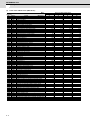
(2) For drive with one unit and two motor
Type
Linear servo motor type
Primary side type
Compatible
servo drive
unit type
Secondary side type
MDS-D2-V1MDS-D2-V2-
MDS-DJ-V1Power facility capacity [kVA]
Rated (natural-cooling) [Arms]
Current
Rated (liquid-cooling) [Arms]
Maximum [Arms]
Cooling method
Rated (natural-cooling) [N]
Thrust
Rated (liquid-cooling) [N]
Maximum [N]
Maximum speed [m/s] (Note 1)
Magnetic attraction force (per one motor) [N]
Primary side [kg]
Mass
Secondary side [kg]
Recommended load mass ratio
Structure
Ambient
temperature
Ambient
Environment humidity
Atmosphere
Vibration
Altitude
LM-FP2A-03M
LM-FP2A-03M
LM-F Series (driving with one unit and two motors )
LM-FP2B-06M LM-FP2D-12M LM-FP2F-18M LM-FP4B-12M
LM-FP2B-06M LM-FP2D-12M LM-FP2F-18M LM-FP4B-12M
LM-FS20- □
80
8040 (L)
8080
16080 (M)
80
4.0
6.9
13.8
52.2
LM-FS20- □
80
8040 (L)
8080
16080 (M)
80
7.0
7.8
15.6
56.2
300
600
1800
600
1200
3600
2500
4500
5×2
5.8 (384mm)
7.1 (480mm )
9.0 (576mm)
LM-FP4D-24M
LM-FP4D-24M
LM-FS20- □
160
LM-FS20- □
320
LM-FS40- □
160
LM-FS40- □
320
16080 (L)
160160
-
16080 (L)
160160
-
15.0
15.1
31.4
111.4
36.0
28.3
57.3
203.9
1200
2400
7200
2400
4800
14400
11.0
20.0
15.3
23.8
30.5
46.4
115.7
169.4
Natural-cooling, liquid-cooling
1200
1800
2400
3600
7200
10800
2.0
9000
13500
9000
9×2
18 × 2
27 × 2
14 × 2
5.8 (384mm)
5.8 (384mm)
5.8 (384mm)
13.5 (480mm)
7.1 (480mm)
7.1 (480mm)
7.1 (480mm)
16.0 (576mm)
9.0 (576mm)
9.0 (576mm)
9.0 (576mm)
15 times linear servo motor primary side mass maximum
Open (Degree of protection IP00)
18000
28 × 2
13.5 (480mm)
16.0 (576mm)
0 to 40°C (with no freezing), Storage: -15°C to 55°C (with no freezing)
80%RH or less (with no dew condensation), Storage: 90%RH or less (with no dew condensation)
Indoors (no direct sunlight); no corrosive gas, inflammable gas, oil mist, or dust
49m/s 2or less
1000 meters or less above sea level
(Note 1) The above value may be limited by the maximum speed of the linear scale.
(Note 2) 400V specification is applied.
2-3
MITSUBISHI CNC
2 Specifications
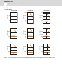
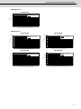
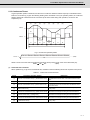
2.1.2 Thrust Characteristics
(1) LM-F Series
LM-FP2A-03M
LM-FP2B-06M
1800
Short time operation
range
0
Short time operation
range
600
300
Continuous operation range
(natural-cooling)
0
1
2
Speed (m/s)
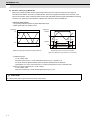
LM-FP2F-18M
900
0
Thrust (N)
Thrust (N)
Short time operation
range
Continuous operation range
(liquid-cooling)
2400
1200
600
Continuous operation range
(natural-cooling)
0
1
2
Speed (m/s)
LM-FP4F-36M
Short time operation
range
3600
1800
0
(Note)
2-4
Continuous operation range
(liquid-cooling)
Short time operation
range
Continuous operation range
(liquid-cooling)
Continuous operation range
(natural-cooling)
1
2
Speed (m/s)
0
1
2
Speed (m/s)
4800
Short time operation
range
2400
1200
Continuous operation range
(natural-cooling)
0
1
2
Speed (m/s)
Continuous operation range
(liquid-cooling)
Continuous operation range
(natural-cooling)
1
2
Speed (m/s)
LM-FP5H-60M
18000
Short time operation
range
2400
Continuous operation range
(natural-cooling)
7200
9600
4800
Continuous operation range
(liquid-cooling)
LM-FP4D-24M
LM-FP4H-48M
Thrust (N)
Thrust (N)
7200
1200
0
1
2
Speed (m/s)
14400
10800
Short time operation
range
600
Continuous operation range
(natural-cooling)
3600
3600
2400
LM-FP4B-12M
5400
1800
Continuous operation range
(liquid-cooling)
Thrust (N)
150
Continuous operation range
(liquid-cooling)
1200
Continuous operation range
(liquid-cooling)
Continuous operation range
(natural-cooling)
1
2
Speed (m/s)
Thrust (N)
300
3600
Thrust (N)
600
Thrust (N)
Thrust (N)
900
LM-FP2D-12M
12000
Short time operation
range
6000
3000
0
Continuous operation range
(liquid-cooling)
Continuous operation range
(natural-cooling)
1
2
Speed (m/s)
The above graphs show the data when applied the input voltage of 200VAC(400VAC for FP5H). When the input
voltage is 200VAC(400VAC for FP5H) or less, the short time operation range is limited.
Linear Motor Specifications and Instruction Manual
2.1 Linear Servo Motor
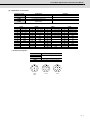
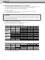
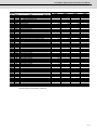
2.1.3 Liquid Cooling Specification
Type
Required cooling ability (W)
LM-FP2A-03M
100
LM-FP2B-06M
100
LM-FP2D-12M
400
LM-FP2F-18M
700
LM-FP4B-12M
400
LM-FP4D-24M
700
LM-FP4F-36M
1000
LM-FP4H-48M
1300
LM-FP5H-60M
2000
Cooling liquid amount
(L/min at 20°C)
5L/min
CAUTION
1. The required cooling capability (W) is not a specified value, but a reference value.
2. Customer is responsible for designing the cooling system, including piping to the coolant pipe embedded in the primary
(coil) side, installing the pipes, and selecting parts, cooling device (chiller) and coolants.
3. Make sure to add an equipment, such as a filter, to the flow path to avoid foreign matters from flowing in the coolant pipe.
4. Customer should select appropriate liquid-cooling pipes and joints so that no leakage will occur. For the liquid-cooling
pipes, select the ones that have enough bending tolerance.
5. We recommend that the liquid poured into the coolant pipe be at room temperature (around 20 degree C) or below.
When the temperature is lower, the cooling effect will be enhanced, but dew condensation may be caused.
6. The coolant pipes are made of copper, so select a rust-preventive agent that won't cause copper corrosion, and add it to
the coolant.
2-5
MITSUBISHI CNC
2 Specifications
2.1.4 Outline Dimension Drawings
< LM-F Series Primary side >
[ LM-FP2A-03M-1WW0 ]
[Unit:mm]
2x2-M8 screw depth 10
1000
170
75
70±0.1
Cabtyre cable for thermistor
(2PNCT-2 cores,
Standard finished outer
diameter: φ9)
31
80
60
12
4 or less
20
(2PNCT-4 cores,
Standard finished outer
diameter: φ12.5)
(100)
21
120
84
(86.5)
Cabtyre cable for thermistor
(18)
(27) 66±0.3
A
(15)
Secondary
side
14
35.5
(27)
B
(10)
(0.5)
(19.5)
50
4 or less
80±0.5
(18)
12.5
(15)
+100
0
(120)
㧔for primary side mounting㧕
2-M5×0.8 screw depth 6
Rc1/4
29.5
12
15
Canon connector
for power
D/MS3106A18-10P
Cannon connector
for thermistor
D/MS3106A14S-9P
35.8
Key
Key
U phase
E㧔Earth㧕
D
A
C
B
G1,G2
(No polarity)
A
B
V phase
W phase
View A
View B
[ LM-FP2B-06M-1WW0 ]
[Unit:mm]
+100
0
70±0.1
(2PNCT-2 cores,
Standard finished outer
diameter:φ9)
120
84
(86.5)
A
4 or less
35.8
40
80
80
60
Secondary
side
14
12
20
(2PNCT-4 cores,
Standard finished outer
diameter:φ12.5)
(18)
(27)
Cabtyre cable for thermistor
(15)
31
21
66±0.3 (27)
B
(10)
(0.5)
(19.5)
50
Cabtyre cable for thermistor
(120)
1000
75
35.5
80±0.5
(18)
12.5
80±0.5
4 or less
(55)
(100)
3×2-M8 screw depth 10
(for primary side mounting)
290
Rc1/4
2-M5×0.8 screw depth 6
29.5
12
15
Canon connector
for power
D/MS3106A18-10P
Cannon connector
for thermistor
D/MS3106A14S-9P
Key
Key
U phase
E㧔Earth㧕
G1,G2
D
C
A
B
B
V phase
W phase
View A
2-6
(No polarity)
A
View B
Linear Motor Specifications and Instruction Manual
2.1 Linear Servo Motor
[ LM-FP2D-12M-1WW0 ]
[Unit:mm]
6×2-M8 screw depth 10
㧔for primary side mounting㧕
+100
0
70±0.1
4 or less
(2PNCT-2 cores,
Standard finished outer
diameter: φ9)
4 or less
20
(2PNCT-4 cores,
Standard finished outer
diameter: φ12.5)
40
5×80(=400)
60
(18)
(27)
Cabtyre cable for thermistor
(15)
12
120
84
(86.5)
A
(10)
Secondary
side
14
21
66±0.3 (27)
B
31
(120)
80±0.5
(0.5)
(19.5)
50
Cabtyre cable for thermistor
35.5
75
(18)
12.5
5×80(=400 Accumulated pitch error±0.5)
(100)
1000
530
(55)
Rc1/4
2-M5×0.8 screw depth 6
29.5
12
15
Canon connector
for power
D/MS3106A18-10P
80
Cannon connector
for thermistor
D/MS3106A14S-9P
35.8
Key
Key
U phase
E㧔Earth㧕
G1,G2
D
A
C
B
(No polarity)
A
B
V phase
W phase
View A
View B
LM-FP2F-18M-1WW0
[Unit:mm]
+100
0
70±0.1
(2PNCT-2 cores,
Standard finished outer
diameter: φ9)
4 or less
20
(2PNCT-4 cores,
Standard finished outer
diameter: φ12.5)
40
8×80(=640)
60
Rc1/4
2-M5×0.8 screw depth 6
29.5
12
15
Canon connector
for power
D/MS3106A18-10P
35.8
80
(18)
(27)
Cabtyre cable for thermistor
(15)
12
120
84
(86.5)
A
(10)
Secondary
side
14
21
66±0.3 (27)
B
31
35.5
80±0.5
(0.5)
(19.5)
50
Cabtyre cable for thermistor
4 or less
75
(18)
12.5
8×80(=640 Accumulated pitch error±0.5)
(120)
1000
770
(55)
(100)
92-M8 screw depth 10
for primary side mounting
Cannon connector
for thermistor
D/MS3106A14S-9P
Key
Key
U phase
E㧔Earth㧕
G1,G2
D
A
C
B
W phase
(No polarity)
B
A
V phase
View A
View B
2-7
MITSUBISHI CNC
2 Specifications
[ LM-FP4B-12M-1WW0 ]
[Unit:mm]
3×3-M8 screw depth 10
for primary side mounting
1000
290
80±0.5
70±0.1
(0.5)
(19.5)
Cabtyre cable for thermistor
Secondary
side
31
25
45
(27)
(2PNCT-4 cores,
Standard finished outer
diameter: φ17)
4 or less
50
(18)
75
200
80±0.5
164
(55)
+100
0
(200)
30
(27)
(2PNCT-2 cores,
Standard finished outer
diameter: φ9)
35.5
Cabtyre cable for thermistor
80
60
15
2-M5×0.8 screw depth 6
Rc1/4
(18)
80
4 or less
(10)
40
35.8
(15)
(125)
73±0.3
B
(180)
30
73±0.3
A
29.5
12
Canon connector
for power
Cannon connector
for thermistor
D/MS3106A24-22P
D/MS3106A14S-9P
Key
Key
U phase
E㧔Earth㧕
D
G1,G2
A
C
(No polarity)
A
B
B
V phase
W phase
View A
View B
[ LM-FP4D-24M-1WW0 ]
[Unit:mm]
63-M8 screw depth 10
㧔for primary side mounting㧕
1000
530
+100
0
80±0.5
Cabtyre cable for thermistor
(0.5)
50
31
25
ί19.5ὸ
Secondary
side
5×80(=400)
60
30
4 or less
40
15
80
2-M5×0.8 screw depth 6
Rc1/4
ί18ὸ
ί27ὸ
(2PNCT-2 cores,
Standard finished outer
diameter: φ9)
35.5
Cabtyre cable for thermistor
ί200ὸ
200
164
ί105ὸ
73±0.3
ί180ὸ
40
A
(10)
35.8
70±0.1
55
73±0.3
ί27ὸ
(2PNCT-4 cores,
Standard finished outer
diameter: φ17)
B
ί15ὸ
ί18ὸ
75
4 or less
ί55ὸ
5×80(=400 Accumulated pitch error±0.5)
29.5
12
Canon connector
for power
Cannon connector
for thermistor
D/MS3106A24-22P
D/MS3106A14S-9P
Key
Key
U phase
E㧔Earth㧕
G1,G2
W phase
D
A
C
B
View A
2-8
(No polarity)
B
A
V phase
View B
Linear Motor Specifications and Instruction Manual
2.1 Linear Servo Motor
[ LM-FP4F-36M-1WW0 ]
[Unit:mm]
93-M8 screw depth 10
for primary side mounting
1000
770
8×80(=640 Accumulated pitch error±0.5)
70±0.1
Secondary
side
(2PNCT-2 cores,
Standard finished outer
diameter: φ9)
(200)
30
35.5
(125)
73±0.3
Cabtyre cable for thermistor
(27)
(180)
30
73±0.3
A
B
60
15
35.8
80
Rc1/4
(18)
(10)
8×80(=640)
40
4 or less
(15)
(0.5)
(19.5)
50
31
25
45
(27)
(2PNCT-4 cores,
Standard finished outer
diameter: φ18.5)
(18)
Cabtyre cable for thermistor
4 or less
80±0.5
200
75
164
(55)
+100
0
2-M5×0.8 screw depth 6
29.5
12
Canon connector
for power
Cannon connector
for thermistor
D/MS3106A24-22P
D/MS3106A14S-9P
Key
Key
U phase
E㧔Earth㧕
G1,G2
D
A
C
B
A
B
(No polarity)
V phase
W phase
View A
View B
[ LM-FP4H-48M-1WW0 ]
[Unit:mm]
123-M8 screw depth 10
㧔for primary side mounting㧕
1000
1010
+100
0
70±0.1
(0.5)
(19.5)
50
31
25
Secondary
side
45
(27)
(2PNCT-4 cores,
Standard finished outer
diameter: φ18.5)
(18)
Cabtyre cable for thermistor
4 or less
80±0.5
200
75
164
(55)
11×80(=880 Accumulated pitch error±0.5)
(2PNCT-2 cores,
Standard finished outer
diameter: φ9)
(200)
30
60
15
Rc1/4
(18)
11×80(=880)
4 or less
(10)
40
80
35.8
35.5
Cabtyre cable for thermistor
(27)
(15)
(125)
73±0.3
B
(180)
30
73±0.3
A
2-M5×0.8 screw depth 6
29.5
12
Canon connector
for power
Cannon connector
for thermistor
D/MS3106A24-22P
D/MS3106A14S-9P
Key
Key
U phase
E㧔Earth㧕
G1,G2
D
A
C
B
W phase
View A
(No polarity)
B
A
V phase
View B
2-9
MITSUBISHI CNC
2 Specifications
[ LM-FP5H-60M-1WW0 ]
[Unit:mm]
124-M8 screw depth 10
for primay side mounting
1000
1010
+100
0
75.5±0.1
80±0.5
Cabtyre cable for thermistor
(240)
30
35.5
(2PNCT-2 cores,
Standard finished outer
diameter: φ9)
(30) 60±0.3
(220)
(145)
240
60±0.3
204
40
A
Cabtyre cable for thermistor
60
15
2-M5×0.8 screw depth 6
Rc1/4
(18)
11×80(=880)
4 or less
(10)
40
80
35.8
Secondary
side
55
60±0.3 (30)
(2PNCT-4 cores,
Standard finished outer
diameter: φ18.5)
B
(15)
(0.5)
(25)
50
31
25
(18)
75
4 or less
(55)
11×80(=880 Accumulated pitch error±0.5)
29.5
12
Canon connector
for power
D/MS3106A24-22P
Cannon connector
for thermistor
D/MS3106A14S-9P
Key
Key
U phase
E㧔Earth㧕
D
C
B
W phase
View A
2 - 10
G1,G2
A
B
A
V phase
View B
(No polarity)
Linear Motor Specifications and Instruction Manual
2.1 Linear Servo Motor
< LM-F Series Secondary side >
[ LM-FS20-384-1WW0, LM-FS20-480-1WW0, LM-FS20-576-1WW0 ]
[Unit:mm]
B-9 drill through
(for secondary side mounting)
0
L -0.2
19.5
48±0.2
M (Accumulated pitch error±0.2)
Stamp "N"
96±0.2
Top
19
9
N
82
(19)
C
1
24
2-
K
(10)
100±0.3
Bottom
(24)
(10.5)
10
Name plate
120
(48)
2×2-M8 screw
(for hanging)
Mold (epoxy)
Variable dimensions
Model
L
M
3X96(=288)
K
336
B
4×2
LM-FS20-384-1WW0
384
LM-FS20-480-1WW0
480
4X96(=384)
432
5×2
LM-FS20-576-1WW0
576
5X96(=480)
528
6×2
[ LM-FS40-480-1WW0, LM-FS40-576-1WW0 ]
[Unit:mm]
B-9 drill through
(for secondary side mounting)
0
L -0.2
(48)
M (Accumulated pitch error±0.2)
48±0.2
19.5
Stamp "N"
(10.5)
96±0.2
Top
180±0.3
162
(19)
1
(10)
C
24
2-
K
200
N
Bottom
(24)
9
19
10
Name plate
2×2-M8 screw
(for hanging)
Mold (epoxy)
Model
Variable dimensions
L
LM-FS40-480-1WW0
480
M
4X96(=384)
K
432
B
5×2
LM-FS40-576-1WW0
576
5X96(=480)
528
6×2
2 - 11
MITSUBISHI CNC
2 Specifications
[ LM-FS50-480-1WW0, LM-FS50-576-1WW0 ]
[Unit:mm]
B-9 drill through
(for secondary side mounting)
0
L -0.2
(48)
M (Accumulated pitch error±0.2)
48±0.2
25
Stamp "N"
(11)
96±0.2
Top
202
(19)
220±0.3
(10)
1
2×2-M8 screw
(for hanging)
Mold (epoxy)
Model
2 - 12
C
24
2-
K
240
N
Bottom
(24)
14
19
10
Name plate
Variable dimensions
L
LM-FS50-480-1WW0
480
M
4X96(=384)
K
432
B
5×2
LM-FS50-576-1WW0
576
5X96(=480)
528
6×2
3
Characteristics
3-1
MITSUBISHI CNC
3 Characteristics
3.1 Linear Servo Motor
3.1.1 Overload Protection Characteristics
The servo drive unit has an electronic thermal relay to protect the servo motor and servo drive unit from overloads. The
operation characteristics of the electronic thermal relay are shown below when standard parameters (SV021=60,
SV022=150) are set. If overload operation over the electronic thermal relay protection curve shown below is carried out,
overload 1 (alarm 50) will occur. If the maximum torque is commanded continuously for one second or more due to a
machine collision, etc., overload 2 (alarm 51) will occur.
(1) Linear motor overload protection characteristics (For natural-cooling)
< MDS-D2 Series >
LM-FP2A-03M
LM-FP2B-06M
10000.0
10000.0
Speed < 60mm/min
Speed < 60mm/min
Speed ≥ 60mm/min
Speed ≥ 60mm/min
1000.0
Time 䋨s䋩
Time 䋨s䋩
1000.0
100.0
100.0
10.0
10.0
1.0
1.0
0.1
0.1
0
100
200
300
400
500
600
700
800
0
900
100
200
300
400
500
LM-FP2D-12M
Speed < 60mm/min
Speed ≥ 60mm/min
1000.0
Time 䋨s䋩
Time 䋨s䋩
Speed < 60mm/min
Speed ≥ 60mm/min
100.0
10.0
1.0
100.0
10.0
1.0
0.1
0.1
0
100
200
300
400
500
600
700
0
800
100
Motor current value (rated current value ratio %)
200
300
400
500
600
700
800
Motor current value (rated current value ratio %)
LM-FP4B-12M
LM-FP4D-24M
10000.0
10000.0
Speed < 60mm/min
Speed < 60mm/min
Speed ≥ 60mm/min
Speed ≥ 60mm/min
1000.0
Time 䋨s䋩
1000.0
Time 䋨s䋩
800
10000.0
1000.0
100.0
10.0
1.0
100.0
10.0
1.0
0.1
0.1
0
100
200
300
400
500
600
700
800
0
100
Motor current value (rated current value ratio %)
200
300
400
500
600
700
800
Motor current value (rated current value ratio %)
LM-FP4F-36M
LM-FP4H-48M
10000.0
10000.0
Speed < 60mm/min
Speed < 60mm/min
Speed ≥ 60mm/min
Speed ≥ 60mm/min
1000.0
Time 䋨s䋩
1000.0
Time 䋨s䋩
700
LM-FP2F-18M
10000.0
100.0
10.0
1.0
100.0
10.0
1.0
0.1
0.1
0
100
200
300
400
500
600
Motor current value (rated current value ratio %)
3-2
600
Motor current value (rated current value ratio %)
Motor current value (rated current value ratio %)
700
800
0
100
200
300
400
500
600
Motor current value (rated current value ratio %)
700
800
Linear Motor Specifications and Instruction Manual
3.1 Linear Servo Motor
< MDS-DH2 Series >
LM-FP5H-60M
10000.0
Speed < 60mm/min
Speed ≥ 60mm/min
Time 䋨s䋩
1000.0
100.0
10.0
1.0
0.1
0
100
200
300
400
500
600
700
800
Motor current value (rated current value ratio %)
< MDS-DJ Series >
LM-FP2A-03M
LM-FP2B-06M
10000.0
10000.0
Speed < 60mm/min
Speed ≥ 60mm/min
1000.0
Time 䋨s䋩
Time 䋨s䋩
Speed < 60mm/min
Speed ≥ 60mm/min
1000.0
100.0
10.0
1.0
100.0
10.0
1.0
0.1
0.1
0
100
200
300
400
500
600
700
800
0
900
100
Motor current value (rated current value ratio %)
200
300
400
500
LM-FP2D-12M
700
800
LM-FP4B-12M
10000.0
10000.0
Speed < 60mm/min
Speed < 60mm/min
Speed ≥ 60mm/min
Speed ≥ 60mm/min
1000.0
Time 䋨s䋩
1000.0
Time 䋨s䋩
600
Motor current value (rated current value ratio %)
100.0
100.0
10.0
10.0
1.0
1.0
0.1
0.1
0
100
200
300
400
500
600
Motor current value (rated current value ratio %)
700
800
0
100
200
300
400
500
600
700
800
Motor current value (rated current value ratio %)
3-3
MITSUBISHI CNC
3 Characteristics
(2) Linear motor overload protection characteristics (For liquid-cooling)
< MDS-D2 Series >
LM-FP2A-03M
LM-FP2B-06M
10000.0
10000.0
Speed < 60mm/min
Speed ≥ 60mm/min
1000.0
Time 䋨s䋩
Time 䋨s䋩
Speed < 60mm/min
Speed ≥ 60mm/min
1000.0
100.0
100.0
10.0
10.0
1.0
1.0
0.1
0.1
0
100
200
300
400
0
500
100
200
300
LM-FP2D-12M
10000.0
Speed < 60mm/min
Speed ≥ 60mm/min
1000.0
Time 䋨s䋩
Time 䋨s䋩
Speed < 60mm/min
Speed ≥ 60mm/min
1000.0
100.0
10.0
1.0
100.0
10.0
1.0
0.1
0.1
0
100
200
300
400
500
0
Motor current value (rated current value ratio %)
100
200
300
LM-FP4B-12M
500
LM-FP4D-24M
10000.0
Speed < 60mm/min
Speed < 60mm/min
Speed ≥ 60mm/min
Speed ≥ 60mm/min
1000.0
Time 䋨s䋩
1000.0
Time 䋨s䋩
400
Motor current value (rated current value ratio %)
10000.0
100.0
100.0
10.0
10.0
1.0
1.0
0.1
0.1
0
100
200
300
400
0
500
100
200
300
400
500
Motor current value (rated current value ratio %)
Motor current value (rated current value ratio %)
LM-FP4F-36M
LM-FP4H-48M
10000.0
10000.0
Speed < 60mm/min
Speed < 60mm/min
Speed ≥ 60mm/min
Speed ≥ 60mm/min
1000.0
Time 䋨s䋩
1000.0
Time 䋨s䋩
500
LM-FP2F-18M
10000.0
100.0
100.0
10.0
10.0
1.0
1.0
0.1
0.1
0
100
200
300
400
Motor current value (rated current value ratio %)
3-4
400
Motor current value (rated current value ratio %)
Motor current value (rated current value ratio %)
500
0
100
200
300
400
Motor current value (rated current value ratio %)
500
Linear Motor Specifications and Instruction Manual
3.1 Linear Servo Motor
< MDS-DH2 Series >
LM-FP5H-60M
10000.0
Speed < 60mm/min
Speed ≥ 60mm/min
Time 䋨s䋩
1000.0
100.0
10.0
1.0
0.1
0
100
200
300
400
500
Motor current value (rated current value ratio %)
< MDS-DJ Series >
LM-FP2A-03M
LM-FP2B-06M
10000.0
10000.0
Speed < 60mm/min
Speed < 60mm/min
Speed ≥ 60mm/min
Time 䋨s䋩
Time 䋨s䋩
1000.0
Speed ≥ 60mm/min
1000.0
100.0
100.0
10.0
10.0
1.0
1.0
0.1
0.1
0
100
200
300
400
0
500
100
200
300
LM-FP2D-12M
500
LM-FP4B-12M
10000.0
10000.0
Speed < 60mm/min
Speed < 60mm/min
Speed ≥ 60mm/min
Speed ≥ 60mm/min
1000.0
Time 䋨s䋩
1000.0
Time 䋨s䋩
400
Motor current value (rated current value ratio %)
Motor current value (rated current value ratio %)
100.0
100.0
10.0
10.0
1.0
1.0
0.1
0.1
0
100
200
300
400
Motor current value (rated current value ratio %)
500
0
100
200
300
400
500
Motor current value (rated current value ratio %)
3-5
MITSUBISHI CNC
3 Characteristics
3.1.2 Dynamic Brake Characteristics
If a servo alarm that cannot control the motor occurs, the dynamic brakes will function to stop the servo motor regardless of
the parameter settings.
Coasting rotation distance during emergency stop
The distance that the motor coasts when stopping with the dynamic brakes can be approximated with the following
expression.
When in position command synchronization system, calculate using one-half of the moving section’s total weight (M).
(
./#:]VG/
#(
$_
LMAX
F0
M
te
A
B
: Coasting distance of machine
: Speed during brake operation
: Moving section’s total weight
: Brake drive relay delay time
: Coefficient A (Refer to the table below)
: Coefficient B (Refer to the table below)
Emergency stop (EMG)
Dynamic brake control output
Actual dynamic brake operation
[m]
[m/min]
[kg]
[s](Normally 0.03s)
OFF
ON
OFF
ON
OFF
ON
Motor speed
N
Coasting distance
Time
te
Dynamic brake braking diagram
< MDS-D2/DH2 Series >
Coasting amount calculation coefficients table
Standard combination
A
B
LM-FP2A-03M
10.02 × 10⁻⁸
30.76 × 10⁻⁴
LM-FP2A-03M
13.22 × 10⁻⁸
93.22 × 10⁻⁴
LM-FP2B-06M
6.68 ×
10-8
10-4
LM-FP2B-06M
9.66 ×
10-8
30.68 × 10⁻⁴
LM-FP2D-12M
2.41 × 10⁻⁸
8.20 × 10⁻⁴
LM-FP2D-12M
4.83 × 10⁻⁸
16.41 × 10⁻⁴
LM-FP2F-18M
1.70 × 10
-8
-4
LM-FP2F-18M
1.40 × 10
-8
22.96 × 10⁻⁴
LM-FP4B-12M
2.09 × 10⁻⁸
7.44 × 10⁻⁴
LM-FP4B-12M
4.19 × 10⁻⁸
14.88 × 10⁻⁴
LM-FP4D-24M
1.07 × 10⁻⁸
3.54 × 10⁻⁴
LM-FP4D-24M
0.78 × 10⁻⁸
19.53 × 10⁻⁴
LM-FP4F-36M
0.32 ×
10-8
-4
LM-FP4H-48M
0.19 × 10⁻⁸
5.26 × 10⁻⁴
LM-FP5H-60M
10-8
1.29 × 10⁻⁴
Motor type
0.42 ×
11.10 ×
Combination with one unit and two motor
Motor type
A
B
4.72 × 10
5.45 × 10
< MDS-DJ Series >
Coasting amount calculation coefficients table
Standard combination
Motor type
A
3-6
B
Combination with one unit and two motor
Motor type
A
B
LM-FP2A-03M
8.75 × 10⁻⁸
35.19 × 10⁻⁴
LM-FP2A-03M
11.10 × 10⁻⁸
110.97 × 10⁻⁴
LM-FP2B-06M
6.03 × 10⁻⁸
12.29 × 10⁻⁴
LM-FP2B-06M
8.37 × 10⁻⁸
35.42 × 10⁻⁴
LM-FP4B-12M
1.79 × 10⁻⁸
8.69 × 10⁻⁴
LM-FP2D-12M
-8
9.48 × 10⁻⁴
2.09 × 10
4
Dedicated Options
4-1
MITSUBISHI CNC
4 Dedicated Options
4.1 Linear Servo Detectors
4.1.1 Absolute Position Detector
The linear scales available in absolute position detection system are listed below.
All the feedback signals are output via Mitsubishi-protocol serial communication (digital signal).
Manufacturer
Detector type
Interface unit type
Minimum detection
resolution
SR77
SR87
Not required
0.05μm
Tolerable maximum
speed
0.1μm
Magnescale Co., Ltd
200m/min
0.01μm
HEIDENHAIN
CORPORATION
Mitutoyo Corporation
FAGOR Automation
Renishaw plc.
LC193M
LC493M
Not required
LC195M
LC495M
Not required
LC215M
AT343
0.05μm
0.01μm
180m/min
0.01μm
0.001μm
180m/min
Not required
0.01μm
180m/mim
Not required
0.05μm
120m/min
AT543
Not required
0.05μm
150m/min
AT545
Not required
0.00488
(20/4096)μm
150m/min
ST748
Not required
0.1μm
300m/s
SAM Series
Not required
0.05μm
120m/min
SVAM Series
Not required
0.05μm
120m/min
GAM Series
Not required
0.05μm
120m/min
LAM Series
Not required
0.1μm
120m/min
RL40N Series
Not required
0.05μm
0.001μm
6,000m/min
< Contact information about detector by other manufacturer >
- Magnescale Co., Ltd.: http://www.mgscale.com/mgs/language/english/
- HEIDENHAIN CORPORATION: http://www.heidenhain.com/
- Mitutoyo Corporation: http://www.mitutoyo.co.jp/eng/
- FAGOR Automation : http://www.fagorautomation.com/
- Renishaw plc.: http://www.renishaw.com/
(Note)
The application may vary due to the specification changes or production discontinuance by the detector
manufacturer. Thus, be sure to carefully check each manufacturer's specifications before use.
CAUTION
1. The above value does not guarantee the accuracy of the system.
2. The user shall prepare the above-mentioned detector after inquiring of each manufacturer about the specifications and
confirm them.
4-2
Linear Motor Specifications and Instruction Manual
4.1 Linear Servo Detectors
4.1.2 Relative Position Detector
Depending on the output signal specifications, select a relative position detector with which the following (a) or (b) is
applied to use with a linear motor.
(a)
Serial signal type (serial conversion unit made by each manufacture)
The following serial conversion unit converts the detector output signal and transmits the signal to the drive unit in
serial communication.
For details on the specifications of each conversion unit scale and for purchase, contact each corresponding
manufacture directly.
Manufacturer
Detector type
Interface unit type
Minimum detection
resolution
SR75
SR85
Not required
0.05μm
Tolerable
maximum speed
0.1μm
Magnescale Co., Ltd
200m/min
0.01μm
HEIDENHAIN CORPORATION
LS187
LS487
EIB192M A4 20μm
EIB392M A4 20μm
0.0012μm
120m/min
< Contact information about detector by other manufacture >
- Magnescale Co., Ltd.: http://www.mgscale.com/mgs/language/english/
- HEIDENHAIN CORPORATION: http://www.heidenhain.com/
CAUTION
The above value does not guarantee the accuracy of the system.
4-3
MITSUBISHI CNC
4 Dedicated Options
(b) SIN wave output (using MDS-B-HR)
When using a relative position detector that the signal is the SIN wave output, the detector output signal is
converted in the detector conversion unit (MDS-B-HR), and then the signal is transmitted to the drive unit in the
serial communication. Select a relative position detector with A/B phase SIN wave signal that satisfies the following
conditions. For details on the specifications of MDS-B-HR, refer to the section "MDS-B-HR".
< Detector output signal >
- 1Vp-p analog A-phase, B-phase, Z-phase differential output
- Output signal frequency 200kHz or less
Voltage [V]
Voltage [V]
A phase
A phase B phase
0.5
360°
0
0
-45° +45°
-45° +45°
Z phase
- 0.5
2.5
Zero crossover
Time
Angle [° ]
A/B phase output signal waveform during forward run
Relationship between A phase and Z phase
(When the differential output waveform is measured)
- Combination speed
In use of linear scale:
Maximum speed (m/min) = Scale analog signal frequency (m) × 200,000 × 60
An actual maximum speed is limited by the mechanical specifications and electrical
specifications, etc. of the connected scale, so contact the manufacture of the purchased scale.
- Division number 512 divisions per 1 cycle of signal
In use of linear scale:
Minimum resolution (m) = Scale analog signal frequency (m) / 512
CAUTION
The above value does not guarantee the accuracy of the system.
4-4
Linear Motor Specifications and Instruction Manual
4.2 Detector Interface Unit
4.2 Detector Interface Unit
4.2.1 Serial Output Interface Unit for ABZ Analog Detector MDS-B-HR
(1)
Functions
[1] Convert the analog waves (Phase A and B) output from the relative position linear scale into the Mitsubishi-protocol
serial communication (digital) signal.
[2] Add the signal from the magnetic polar detection unit to the linear scale's feedback signal.
Relative position linear scale
output signal
Voltage [V]
0.5
A phase ޓB phase
Servo drive unit
㧔MDS-D2/DH2㧕
0
Analog signal
- 0.5
Digital signal
Time
Pole position data
Detector interface unit
㧔MDS-B-HR㧕
Pole detection unit
㧔MDS-B-MD㧕
CAUTION
Always connect MDS-B-MD when using MDS-B-HR.
(2)
Type configuration
MDS-B-HR-11M (1)
(1) Degree of protection
Symbol Degree of protection
None
IP65
P
IP67
4-5
MITSUBISHI CNC
4 Dedicated Options
(3) Specifications
MDS-B-HR-
Unit Type
11M
11MP
A-phase, B-phase, Z-phase
2.5V reference Amplitude 1VP-P
Analog input specifications
Compatible frequency
Analog raw waveform max.200kHz
Scale resolution
Analog raw waveform/512 division
Input/output communication style
High-speed serial communication I/F, RS485 or equivalent
Availability of pole detector
Available
Working ambient temperature
0 to 55°C
Operation ambient relative humidity
90%RH or less (with no dew condensation)
Atmosphere
No toxic gases
Tolerable vibration
98 m/s2 (10G)
Tolerable impact
294 m/s2 (30G)
DC5V ± 5%
Tolerable power voltage
Maximum heating value
2W
Mass
0.5kg or less
Degree of protection
IP65
IP67
(4) Outline dimension drawings
MDS-B-HR
152
5ޓ
6.5
46
CON4
70
CON1
CON3
RM15WTR-10S
CON2
RM15WTR-12S
5ޓ
RM15WTR-8Px2
6.5
40
4-5 DIA.
165
4-6
[Unit:mm]
Linear Motor Specifications and Instruction Manual
4.2 Detector Interface Unit
(5)
Explanation of connectors
Connector name
CON1
Application
For connection with servo drive unit (2nd system)
CON2
For connection with servo drive unit
CON3
For connection with scale
CON4
For connection with pole detection unit
(MDS-B-MD)
Pin No.
1
2
3
4
5
6
7
8
CON1
Function
RQ+ signal
RQ- signal
SD+ signal
SD- signal
P5
P5
GND
GND
Pin No.
1
2
3
4
5
6
7
8
CON2
Function
RQ+ signal
RQ- signal
SD+ signal
SD- signal
P5
P5
GND
GND
Pin No.
1
2
3
4
5
6
7
8
9
10
11
12
Remarks
Not provided for 1-part system specifications
CON3
Function
A+ phase signal
A- phase signal
B+ phase signal
B- phase signal
Z+ phase signal
Z- phase signal
P5
GND
Pin No.
1
2
3
4
5
6
7
8
9
10
CON4
Function
A phase signal
REF signal
B phase signal
REF signal
P24
MOH signal
P5
P5
TH signal
GND
< Connector pin layout >
Connector
CON1
CON2
CON3
RM15WTR-12S (Hirose Electric)
CON4
RM15WTR-10S (Hirose Electric)
4
CON1
CON2
9 1
8
6
8
3
RM15WTR- 8P (Hirose Electric)
7
1
2
Type
5
7
6
11
5
10
4
CON3
1
8
7
2
12
3
9
2
10
6
5
3
4
CON4
4-7
MITSUBISHI CNC
4 Dedicated Options
4.2.2 Serial Output Interface Unit for ABZ Analog Detector EIB192M
(Other Manufacturer's Product)
(1) Appearance
(2) Specifications
Type
EIB192M A4 20μm
Manufacturer
EIB192M C4 1200
EIB192M C4 2048
HEIDENHAIN CORPORATION
Input signal
A-phase, B-phase: SIN wave 1Vpp, Z-phase
Maximum input frequency
400kHz
Output signal
Mitsubishi high-speed serial signal (MITSU02-4)
Interpolation division number
Compatible detector
Minimum detection resolution
Maximum 16384 divisions
LS187, LS487
ERM280 1200
ERM280 2048
0.0012μm
0.0000183°
(19,660,800p/rev)
0.0000107°
(33,554,432p/rev)
Working temperature
0°C to 70°C
Degree of protection
IP65
Mass
300g
(3) Outline dimension drawings
98
38.5±1
21.5
64
36±0.2
86±0.2
M4
㧔Note㧕
Ǿ4.5
14.5
7±1
Ǿ7.5
㧔Note㧕Two fixing screws㧔M4×16 DIN 912/ISO 4762㧕
[Unit : mm]
CAUTION
These are other manufacturer's products. When purchasing these products, refer to the manufacturer's information
materials for the product specifications.
4-8
Linear Motor Specifications and Instruction Manual
4.2 Detector Interface Unit
4.2.3 Serial Output Interface Unit for ABZ Analog Detector EIB392M
(Other Manufacturer's Product)
(1)
Appearance
(2) Specifications
Type
EIB392M A4 20μm
Manufacturer
Input signal
400kHz
Mitsubishi high-speed serial signal (MITSU02-4)
Interpolation division number
Compatible detector
Minimum detection resolution
Maximum 16384 divisions
LS187, LS487
ERM280 1200
ERM280 2048
0.0012μm
0.0000183°
(19,660,800p/rev)
0.0000107°
(33,554,432p/rev)
Working temperature
(3)
EIB392M C4 2048
A-phase, B-phase: SIN wave 1Vpp, Z-phase
Maximum input frequency
Output signal
EIB392M C4 1200
HEIDENHAIN CORPORATION
0°C to 70°C
Degree of protection
IP40
Mass
140g
Outline dimension drawings
UNC 4/40
43
Φ4.5
33.3
16.6
76.5
[Unit : mm]
CAUTION
These are other manufacturer's products. When purchasing these products, refer to the manufacturer's information
materials for the product specifications.
4-9
MITSUBISHI CNC
4 Dedicated Options
4.3 Pole Detection Unit (MDS-B-MD)
(1) Functions
Detect the magnetic pole of the linear motor's secondary side magnet, and output it as an analog signal.
When you use a relative position specification scale in combination with MDS-B-HR, you don't have to adjust the
magnetic pole when the power is turned ON. Thus, attach this unit instead.
(2) Type configuration
MDS-B-MD-480 (1)
(1) Degree of protection
Symbol Degree of protection
None
IP65
P
IP67
(3) Specifications
Unit type
MDS-B-MD
480
Working ambient temperature
Operation ambient relative humidity
90%RH or less (with no dew condensation)
Atmosphere
No toxic gases
Tolerable vibration
98m/s2
Tolerable impact
294m/s2
DC5V ± 5%
Tolerable power voltage
Maximum heating
1W or less
0.1 ㎏ or less
Mass
Degree of protection
4 - 10
480P
0 to 55°C
IP65
IP67
Linear Motor Specifications and Instruction Manual
4.3 Pole Detection Unit (MDS-B-MD)
(4)
Outline dimension drawings
[Unit:mm]
(5)
Explanation of connector
Connector name
CON1
Application
Detect the magnetic pole of the linear servo
motor's secondary side magnet, and output
it as an analog signal.
Remarks
Connect to the scale interface unit (MDS-B-HR).
CON1
Function
A-phase signal
REF signal
B-phase signal
REFsignal
TH signal
P5(5Vdc)
P5(5Vdc)
GND
Pin No.
1
2
3
4
5
6
7
8
7
1
6
8
2
3
5
4
Connector to be used
RM15WTR-8P(Hirose Electric)
4 - 11
MITSUBISHI CNC
4 Dedicated Options
4.4 Cables and Connectors
4.4.1 Cable Connection Diagram
The cables and connectors that can be ordered from Mitsubishi Electric Corp. are shown below. Cables can only be
ordered in the designated lengths. Purchase a connector set, etc., to create special length cables.
< MDS-D2/DH2 Series >
1-axis
servo drive unit
(MDS-D2/DH2-V1)
Spindle
2-axis
drive unit
servo drive unit
(MDS-D2/DH2-V2) (MDS-D2/DH2-SP)
Power supply
unit
(MDS-D2/DH2-CV)
< Built in cell battery >
Battery cable
From NC
Power supply
communication
cable
CN2
Optical
communication
cable
Optical
communication
cable
Cell battery built in drive unit
(ER6V-C119B)
CN4
CN24
CN2
CN2L
CN3L
For external
emergency
stop
CN2M
CN3M
Built in cell battery
for servo drive unit
or
option battery
MDS-D2 Series:
3-phase 200VAC power supply
MDS-DH2 Series:
3-phase 400VAC power supply
<Option battery>
Battery case
(MDS-BTCASE+A6BAT)
CN3
CN23
Battery unit
(MDS-BTBOX-36)
L+
L-
Circuit protector or
protection fuse
(Note) Prepared by user.
Power
connector
To 2nd
axis servo
Circuit protector
(Note) Prepared
by user.
AC reactor
(D/DH-AL)
Contactor
(Note) Prepared
by user.
Power
connector
Contactor control output
To 3rd
axis servo
The circuit of external
power supply or
dynamic brake unit (for
large capacity), etc is
required.
Servo detector cable
< Motor side detector cable >
Power cable (Only connector is supplied.)
Spindle detector cable
< Motor side PLG cable >
Spindle detector cable
< Spindle side detector cable >
Linear motor
Praimary side
Linear motor
Secondary side
Power cable (Only connector is supplied.)
4 - 12
Spindle motor
Spindle side detector
Linear scale
Linear Motor Specifications and Instruction Manual
4.4 Cables and Connectors
< MDS-DJ Series >
3-phase
200 to 230VAC
L1
L2
L3
Circuit
protector
or
fuse
Circuit protector
(Note)
Prepared by user
Circuit
protector
or
fuse
Circuit protector
(Note)
Prepared by user
Circuit
protector
or
fuse
Circuit protector
(Note)
Prepared by user
Circuit
protector
or
fuse
Circuit protector
(Note)
Prepared by user
(Note)
Prepared
by user
Contactor
(Note)
Prepared by user
(Note)
Prepared
by user
Contactor
(Note)
Prepared by user
(Note)
Prepared
by user
Contactor
(Note)
Prepared by user
(Note)
Prepared
by user
Contactor
(Note)
Prepared by user
Servo
drive unit
(MDS-DJ-V1)
Option
Option
Spindle
drive unit
(MDS-DJ-SP)
Servo
drive unit
(MDS-DJ-V2)
L1 L2 L3
Spindle
drive unit
(MDS-DJ-SP2)
L1 L2 L3
㪚
㪥
㪌
From NC
L21
CN1B
U V W
CN2
㪚
㪥
㪏
㪬
㪭
CN1B
㪚
㪥
㪈
㪙
㪚
㪥
㪋
L11
C
L21
㪚
㪥
㪉
㪘
㪚
㪥
㪉
㪙
CN2L
To 2nd
axis servo
CN1A
L21
CN1B
U V W
CN2
CN2M
㪚
㪥
㪊
㪣㪊
㪚
㪥
㪏
CN1A
㪚
㪥
㪈
㪘
㪬
㪭
㪬
㪭
㪚
㪥
㪈
㪙
CN2L
㪚
㪥
㪉
㪘
㪚
㪥
㪉
㪙
㪚
㪥
㪋
CN2M
CN3
To 3rd
axis servo
To 5th
axis spindle
To servo detector
To 6th
axis spindle
To spindle detector
(Note) As for 2-axis drive unit, machine side
detector connection is not available.
Servo detector cable
< Motor side detector cable >
㪣㪈
㪣㪉
U V W
U V W
BAT
BAT
L11
P
CN1A
㪚
㪥
㪈
㪘
㪬
㪭
CNP1
Regenerative
resistor
CNP1
㪣㪊
U V W
U V W
Regenerative
resistor
㪚
㪥
㪊
CNP3M CNP3L CNP2
L21
CN1A
CNP3 CNP2
C
CNP1
L11
P
L11
㪚
㪥
㪌
L1 L2 L3
㪣㪈
㪣㪉
CNP3M CNP3L CNP2
CNP1
Regenerative
resistor
CNP3 CNP2
L1 L2 L3
Regenerative
resistor
(Note) As for 2-axis drive unit, machine side
detector connection is not available.
Linear motor
Praimary side
Linear motor
Secondary side
Linear scale
Power cable (Only connector is supplied.)
Spindle motor
Spindle side detector
4 - 13
MITSUBISHI CNC
4 Dedicated Options
4.4.2 Example of the Detector Conversion Unit Connection
(1) For the absolute position detector connection
MDS-D2-Vx
CN2L
Absolute position linear scale
(2) For the relative position detector connection
MDS-D2-Vx
CN2L
Pole detection unit
MDS-B-MD
Scale interface unit
MDS-B-HR
CON2
CON4
CON3
Relative position linear scale
4 - 14
Linear Motor Specifications and Instruction Manual
4.4 Cables and Connectors
4.4.3 List of Cables and Connectors
< Servo detector cable and connector >
Item
MDS-B-HR unit cable
Model
CNV2E-HP- □ M
□ : Length
2, 3, 4, 5,
7, 10, 15, 20,
25, 30m
Contents
Servo drive unit side connector
MDS-B-HR unit side connector
(3M)
(Hirose Electric)
Receptacle : 36210-0100PL
Plug : RM15WTP-8S
Shell kit
: 36310-3200-008 (MOLEX)
Clamp : RM15WTP-CP (10)
Connector set: 54599-1019
For CN2
Pole detection unit
connection cable
CNLH4MD
CNEHRS(10)
For MDS-BHR unit
For CN2
MDS-B-HR connector
Applicable cable outline
ø8.5 to 11mm
Servo detector
connector
CNU2S(AWG18)
MDS-B-HR unit side connector
(Hirose Electric)
Connector: RM15WTP-10P
Clamp: RM15WTP-CP(10)
MDS-B-MD unit side connector
(Hirose Electric)
Connector: RM15WTP-8S
Clamp: RM15WTP-CP(10)
MDS-B-HR unit side connector
(Hirose Electric)
Plug : RM15WTP-8S (for CON1, 2)
RM15WTP-10P(for CON4)
RM15WTP-12P (for CON3)
Clamp : RM15WTP-CP (10)
Servo drive unit side connector
(3M)
Receptacle : 36210-0100PL
Shell kit
: 36310-3200-008
(MOLEX)
Connector set: 54599-1019
< Brake connector >
Item
For CN20
Brake connector for
motor brake control
output
Model
CNU20S(AWG14)
Contents
Servo drive unit side connector
(DDK)
Connector : DK-3200S-03R
Contact: DK-3REC2LLP1-100
4 - 15
MITSUBISHI CNC
4 Dedicated Options
< Power connector >
Item
For
motor
power
For
thermist
or
Power connector for
LM-FP2A-03M
LM-FP2B-06M
LM-FP2D-12M
LM-FP2F-18M
Power connector for
LM-FP4B-12M
LM-FP4D-24M
LM-FP4F-36M
LM-FP4H-48M
LM-FP5H-60M
Thermistor connector for
LM-FP
Power connector for
MDS-D2-V1-20 to 80
Model
Applicable cable outline
ø10.5 to 14mm
4 - 16
Linear motor side power connector
(DDK)
Receptacle: D/MS3101A24-22P
Clamp: D/MS3057-16A
Applicable cable outline
ø12.5 to 16mm
Linear motor side power connector
(DDK)
Receptacle:D/MS3101A14S-9P
Receptacle:D/MS3057-6A
Applicable cable outline
ø6.8 to 10mm
CNU1S(AWG14)
For TE1
Power connector for
MDS-D2-V1-160
Contents
Linear motor side power connector
(DDK)
Receptacle: D/MS3101A18-10P
Clamp: D/MS3057-10A
CNU1S(AWG10)
Drive unit side power connector
(DDK)
Housing: DK-5200S-04R
Contact: DK-5RECSLP1-100
Drive unit side power connector
(DDK)
Housing: DK-5200S-04R
Contact: DK-5RECMLP1-100
Linear Motor Specifications and Instruction Manual
4.4 Cables and Connectors
4.4.4 Cable Connection Diagram
CAUTION
1. Take care not to mistake the connection when manufacturing the detector cable. Failure to observe this could lead to
faults, runaway or fire.
2. When manufacturing the cable, do not connect anything to pins which have no description.
Servo detector cable
< Connection diagram between servo drive unit and scale interface unit >
Servo drive unit side connector
(3M)
Receptacle: 36210-0100PL
Shell kit: 36310-3200-008
(MOLEX)
Connector set: 54599-1019
MDS-B-HR unit side connector
Plug: RM15WTP-8S
Clamp: RM15WTP-CP (10)
0.5mm2
P5(+5V)
LG
1
2
RQ
RQ*
10
3
4
SD
SD*
7
8
0.5mm2
0.2mm2
0.2mm2
5
7
6
8
P5(+5V)
LG
P5(+5V)
LG
1
2
RQ
RQ*
3
4
SD
SD*
PE Case
grounding
MT1
MT2
Case
grounding
5
6
PE
0.2mm2
MT1
MT2
< Cable connection diagram between scale interface unit and magnetic pole detection unit (CNLH4MD) >
MDS-B-HR unit side connector
Connector㧦RM15WTP-10P
Clamp㧦MR15WTP-CP(10)
MDS-B-MD unit side connector
Connector:RM15WTP-8S
Clamp:MR15WTP-CP(10)
1
1
1MA+
2
2
MA-
3
3
MB+
4
4
MB-
9
5
TH
7
6
P5(+5V)
8
7
P5(+5V)
10
8
LG
FG
FG
Case
grounding
4 - 17
MITSUBISHI CNC
4 Dedicated Options
< Cable connection diagram between scale interface unit and scale (CNLH3 cable, etc.) >
Detector conversion unit side connector
Plug: RM15WTP-12P
Clamp: RM15WTP-CP (10)
9
10
7
8
1
2
3
4
5
6
SD
SD㧖
RQ
RQ㧖
A+
AB+
BR+
R-
11
P5(+5V)
12
LG
PE
Case
grounding
(Note) This cable must be prepared by the user.
< Serial communication detector (linear scale, etc.) cable connection diagram >
Servo drive unit side connector
(3M)
Receptacle: 36210-0100PL
Shell kit: 36310-3200-008
(MOLEX)
Connector set: 54599-1019
Machine side serial
communication detector
0.5mm2
P5(+5V)
LG
RQ
RQ*
SD
SD*
1
2
9
10
3
4
7
8
5
MT1
MT2
6
PE
Case
grounding
0.5mm2
0.2mm2
0.2mm2
0.2mm2
(Note) This cable must be prepared by the user.
POINT
For compatible detector, refer to the section "Dedicated Options".
4 - 18
P5(+5V) (Note) Contact the detector
manufacture about
LG
whether to perform
the P5V wiring or not.
RQ
RQ*
SD
SD*
Case
grounding
MT1
MT2
Contact the detector manufacture
for the details.
Linear Motor Specifications and Instruction Manual
4.4 Cables and Connectors
4.4.5 Connector Outline Dimension Drawings
(1) Servo detector connector
MDS-B-HR connector
[Unit: mm]
M16×0.75
23
Manufacturer: Hirose Electric
<Type>
Plug:
RM15WTP-8S (for CON1, 2)
RM15WTP-12P (for CON3)
15.2
M19×1
36.8
[Unit: mm]
M16×0.75
20
10.5
8.5
19
Manufacturer: Hirose Electric
<Type>
Clamp: RM15WTP-CP(10)
Servo drive unit connector for CN2/3
[Unit: mm]
Manufacturer: 3M
<Type>
Receptacle: 36210-0100PL
Shell kit: 36310-3200-008
11
33.9
22.7
Manufacturer: MOLEX
<Type>
Connector set: 54599-1019
8
22.4
10
Brake connector
Brake connector for motor brake control output
[Unit: mm]
19.24
22.8
Manufacturer: DDK
<Type>
Connector: DK-3200S-03R
29.70
㧝
㧞
㧟
6.55
㧝 㧞㧟
7.15
(2)
㧭
5.08
4 - 19
MITSUBISHI CNC
4 Dedicated Options
(3) Power connector
Motor power connector
[Unit: mm]
L
W
B
N
Manufacturer: DDK
V
A
Receptacle:
Type
D/MS3101A14S-9P
D/MS3101A18-10P
D/MS3101A24-22P
Overall screw
Avail. screw
length
Total
length
Outer dia.
A
B or more
7/8-20UNEF
1 1/8-18UNEF
1 1/2-18UNEF
9.53
15.88
15.88
L ± 1.5
37.5
51.1
57.2
ΦN ± 0.5
22.29
28.64
38.17
Cable clamp
fitting screw
Avail. screw
length
V
W or more
3/4-20UNEF
1-20UNEF
1 7/16-18UNEF
9.53
9.53
9.53
[Unit: mm]
A
ΦE
C
Manufacturer: DDK
B
G
V screw
ΦD
Clamp:
Type
A ± 0.7
B ± 0.7
C
D
E
G ± 0.7
V screw
D/MS3057-6A
D/MS3057-10A
D/MS3057-16A
22.2
23.8
23.8
24.6
30.1
35.0
10.3
10.3
10.3
11.2
15.9
19.0
7.9
14.3
15.9
27.0
31.7
37.3
3/4-20UNEF
1-20UNEF
1 3/16-18UNEF
Provided bushing
type
AN3420-6
AN3420-10
AN3420-12
Power connector for drive unit TE1
[Unit: mm]
㧝 㧞 㧟 㧠
56.08
10.5
48.48
10.16
4 - 20
9.1
Manufacturer: DDK
<Type>
Housing: DK-5200S-04R
30.5
44.08
付録
55
章
Selection
5-1
MITSUBISHI CNC
5 Selection
5.1 Selection of the Linear Servo Motor
It is important to select a linear servo motor matched to the purpose of the machine that will be installed. If the linear
servo motor and machine to be installed do not match, the motor performance cannot be fully realized, and it will also be
difficult to adjust the parameters. Be sure to understand the linear servo motor characteristics in this chapter to select the
correct motor.
5.1.1 Max. Feedrate
The max. feedrate for the LM-F Series linear servo motor is 120m/min. However, there are systems that cannot reach
the max. speed 120m/min depending on the linear scale being used.
5.1.2 Selection of Linear Servo Motor Capacity
The following three elements are used to determine the linear motor capacity.
1. Load weight ratio
2. Short time characteristics (acceleration/deceleration torque)
3. Continuous thrust
Carry out appropriate measures, such as increasing the motor capacity, if any of the above conditions is not fulfilled.
(1) Load weight ratio
Each linear motor has an appropriate load weight ratio. The control becomes unstable when the load weight ratio is too
large, and the servo parameter adjustment becomes difficult. It becomes difficult to improve the surface precision in the
feed axis, and the positioning time cannot be shortened in the positioning axis because the settling time is longer.
If the load weight ratio exceeds the recommended value in the section "2.1 Linear Servo Motor", increase the motor
capacity, and select so that the load inertia ratio is within the recommended range.
Note that the recommended value for the load inertia ratio is strictly one guideline. This does not mean that controlling of
the load weight exceeding the recommended value is impossible.
POINT
When selecting feed axis servo motors for NC unit machine tools, place importance on the surface precision during
machining. To do this, always select a servo motor with a load weight ratio within the recommended value. Select the
lowest value possible within that range.
(2) Short time characteristics
In addition to the continuous operation range, the linear motor has the short time operation range that can be used only
in a short time such as acceleration/deceleration. If the motor is a natural-cooling type, a thrust that is approx. 6-fold can
be output. For an oil-type motor, a thrust that is approx. 3-fold can be output. This range is expressed by the maximum
thrust and the thrust characteristics. The maximum thrust or the thrust characteristics differ according to each motor, so
confirm the specifications in section "2.1 Linear Servo Motor".
The thrust required for the linear motor’s acceleration/deceleration differs according to the CNC’s command pattern or
the servo’s position control method.
Determine the required maximum motor thrust from the following expression, and select the linear motor capacity.
(a) Selection with the maximum thrust characteristics
In a low-speed operation range (approximately less than half of the linear motor maximum speed), the linear
acceleration/deceleration time constant "ta" that can be driven depends on the motor maximum thrust. That can be
approximated from the machine specifications using the expression (5-1).
5-2
Linear Motor Specifications and Instruction Manual
5.1 Selection of the Linear Servo Motor
ta =
( TMAX
+TL)
(ms)
••• (5-1)
N
JL
: Motor reach speed
: Motor load mass (except motor primary side)
(m/s)
(kg)
JM
: Motor primary side mass
: Drive system efficiency (Normally 0.8 to 0.95)
: Maximum motor thrust
(kg)
η
TMAX
(N)
TL
: Motor shaft conversion load (friction) force
(N)
Using the approximate linear acceleration/deceleration time constant "ta" calculated above, confirm the thrust
characteristics of the high-speed rotation range in the CNC’s command pattern or the servo’s position control
method.
(b)
Approximation when using the NC command linear acceleration/deceleration pattern + servo standard position
control
This is a normal command pattern or servo standard position control method.
Using the expression (5-2) and (5-3), approximate the maximum torque "Ta1" and maximum torque occurrence
speed "Nm" required for this acceleration/deceleration pattern.
Ta1 =
-Kpta
1000
(1- e
ta
Nm =N{1-
Motor speed
(m/s)
1000 (1- e-Kpta
1000 )}
Kpta
(m/s)
)+TL
(N)
••• (5-2)
•••(5-3)
N
JL
: Motor reach speed
: Motor load mass (except motor primary side)
(m/s)
(kg)
JM
: Motor primary side mass
: Drive system efficiency (Normally 0.8 to 0.95)
: Maximum motor thrust
(kg)
η
TMAX
TL
: Motor shaft conversion load (friction) force
(N)
(N)
NC command
N
Nm
Motor actual speed
0
Motor
acceleration
ta
Time (ms)
Ac
Motor acceleration
Motor
thrust
(N)
Speed most required
for the motor thrust
Ta 1
TL
0
ta
0
Time (ms)
Nm
N
Motor speed
(m/s)
Fig.1 Speed, acceleration and thrust characteristics when using the NC command linear
acceleration/deceleration pattern + servo standard position control
5-3
MITSUBISHI CNC
5 Selection
(c)
Approximation when using the NC command linear acceleration/deceleration pattern + servo SHG control (option)
This is a servo’s position control method to achieve a normal command pattern and high precision. SHG control
improves the position loop gain by stably controlling a delay of the position loop in the servo system. This allows the
settling time to be reduced and a high precision to be achieved.
Using the expression (5-4) and (5-5), approximate the maximum torque "Ta1" and maximum torque occurrence
speed "Nm" required for this acceleration/deceleration pattern.
Ta1 =
ta
Nm =N{1-
Motor speed
(m/s)
-2Kpta
1000
(1- 0.58 e
-2Kpta
1000
(1-1.5e 1000 )}
1.3Kpta
(N)
)+TL
(m/s)
••• (5-4)
••• (5-5)
N
JL
: Motor reach speed
: Motor load mass (except motor primary side)
(m/s)
(kg)
JM
: Motor primary side mass
: Drive system efficiency (Normally 0.8 to 0.95)
: Maximum motor thrust
(kg)
η
TMAX
(N)
TL
: Motor shaft conversion load (friction) force
(N)
NC command
N
Nm
Motor actual speed
0
ta
Motor
acceleration
Time (ms)
Ac
Motor
thrust
(N)
Speed most required
for the motor thrust
Ta 1
Motor acceleration
TL
0
ta
0
Time (ms)
Nm
N
Motor speed
(m/s)
Fig.2 Speed, acceleration and thrust characteristics when using the NC command linear
acceleration/deceleration pattern + servo SHG control
5-4
Linear Motor Specifications and Instruction Manual
5.1 Selection of the Linear Servo Motor
(d)
Approximation when using the NC command soft acceleration/deceleration pattern + feed forward (high-speed
accuracy) control
If the feed forward amount is set properly, the delay of the servo position loop is guaranteed. Therefore, this
command acceleration pattern can be approximated to the NC command and does not depend on the servo
position control method.
Using the expression (5-6) and (5-7), approximate the maximum torque "Ta1" and maximum torque occurrence
speed "Nm" required for this acceleration/deceleration pattern.
Ta1 =
+TL
ta
Nm =N(1-
tb
1
2
ta
••• (5-6)
••• (5-7)
ta
tb
Kp
N
JL
: Linear acceleration/deceleration time constant
: Acceleration/deceleration time constant
: Position loop gain
: Motor reach speed
: Motor load mass (except motor primary side)
(ms)
(ms)
(rad/sec)
(m/s)
(kg)
JM
: Motor primary side mass
: Drive system efficiency (Normally 0.8 to 0.95)
: Motor shaft conversion load (friction) force
(kg)
η
TL
Motor speed
(m/s)
(m/s)
(N)
(N)
NC commandѳMotor actual speed
N
Nm
0
ta
ta+tb
Motor
acceleration
Time (ms)
Ac
Motor
thrust
(N)
Ta 1
Speed most required
for the motor thrust
TL
0
tb
ta ta+ tb
0
Time (ms)
Nm
N
Motor speed
(m/s)
Fig 3. Speed, acceleration and thrust characteristic when using the NC command soft
acceleration/deceleration pattern + feed forward (high-speed accuracy) control
5-5
MITSUBISHI CNC
5 Selection
(e) Confirmation in the thrust characteristics
Confirm whether the maximum thrust "Ta1" and maximum thrust occurrence speed "Nm" required for this
acceleration/deceleration pattern calculated in the item "(b)" to "(d)" are in the short time operation range of the
thrust characteristics.
Motor maximum thrust
100
Required maximum thrust : Ta 1
Required maximum thrust occurrence speed : Nm
80
Thrust [N]
High-speed operation range
thrust characteristic
60
Short time operation range
40
20
Continuous operation range
0
0
2000
4000
Speed [m/s]
Motor thrust characteristics
If they are not in the short time operation range, return to the item "(b)" to "(d)" and make the linear acceleration/
deceleration time constant "ta" large.
If the acceleration specification cannot be changed (the linear acceleration/deceleration time constant cannot be
increased), reconsider the selection, such as increasing the motor capacity.
POINT
1. In selecting the maximum thrust "Ta1" required for this acceleration/deceleration pattern, the measure of it is 80% of the
motor maximum thrust "TMAX "
2. In high-speed rotation range, confirm that the maximum thrust "Ta1" and maximum thrust occurrence speed "Nm"
required for this acceleration/deceleration is in the short time operation range.
3. The drive system efficiency is normally approx. 0.95 in the ball screw mechanism and approx. 0.8 in the gear mechanism
4. For the thrust characteristics in the motor high-speed operation range, the AC input voltage is 200V (200V series) or
380V (400V series). If the input voltage is low or if the power wire connecting the linear motor and drive unit is long (20m
length), the short time operation range is limited. In this case, an allowance must be provided for the selection of the
high-speed operation range.
5-6
Linear Motor Specifications and Instruction Manual
5.1 Selection of the Linear Servo Motor
5.1.3 Continuous Thrust
A typical operation pattern is assumed, and the motor's continuous effective load thrust (Frms) is calculated from the
load force. If numbers (1) to (8) in the following drawing were considered a one cycle operation pattern, the continuous
effective load thrust is obtained from the root mean square of the thrust during each operation, as shown in the
expression (5-8).
(1)
Motor
(2)
(3)
(4)
(5)
(6)
(7)
(8)
0
F1
F7
F4
F2
Motor
0
F3
F8
F6
Time
F5
t1
t2
t3
t4
t5
t6
t7
t8
t0
Fig. 5-1Continuous operation pattern
F r ms 㧩
F 12㨯t 1㧗F 22㨯t 2㧗F 32㨯t 3㧗F 42㨯t 4㧗F 52㨯t 5㧗F 62㨯t 6㧗F 72㨯t 7㧗F 82㨯t 8
㨯㨯㨯㧔5-8㧕
t0
Select a motor so that the continuous effective load thrust (Frms) is 80% or less of the motor rated thrust (Fs).
Frms ≦ 0.8 × Fs
…(5-9)
(1)
Horizontal axis load thrust
When operations (1) to (8) are for a horizontal axis, calculate so that the following thrusts are required in each period.
Table 5-1 Load thrusts of horizontal axes
Period
Load thrust calculation method
(1)
(Amount of acceleration thrust) + (Kinetic friction force)
(2)
(Kinetic friction force) + (Cutting force)
(3)
(Amount of deceleration thrust) +(Kinetic friction force)
(4)
(5)
(6)
(7)
(8)
Explanation
Normally the acceleration/deceleration time constant is
calculated so this thrust is 80% of the maximum thrust of the
motor.
The signs for the amount of acceleration thrust and amount
of deceleration thrust are reversed when the absolute value
is the same value.
Calculate so that the static friction force is always required
(Static friction force)
during a stop.
The signs are reversed with period (1) when the kinetic
- (Amount of acceleration thrust) - (Kinetic friction force)
friction does not change according to movement direction.
The signs are reversed with period (2) when the kinetic
- (Kinetic friction force) - (Cutting force)
friction does not change according to movement direction.
The signs are reversed with period (3) when the kinetic
- (Amount of deceleration thrust) - (Kinetic friction force)
friction does not change according to movement direction.
Calculate so that the static friction force is always required
- (Static friction force)
during a stop.
5-7
MITSUBISHI CNC
5 Selection
(2) Max. cutting thrust and max. cutting duty
If the max. cutting force and max. cutting duty (%/min) are known, the following expression can be used for the selection
conditions.
(U҈(E
&
…(5-10)
Fs : Motor continuous thrust (N)
Fc : Max. cutting force during operation (N)
D : Max. cutting duty (%/min)
(3) Unbalance axis
CAUTION
When using the linear servo motor for an unbalance axis, adjust the unbalance weight to 0 by installing an air cylinder, etc.
on the machine side. The unbalance weight disables the initial magnetic pole adjustment.
5.2 Selection of the Power Supply Unit (Only MDS-D2/DH2)
Compared to the normal rotary motor, when using the linear servo system, the instantaneous output, such as the
acceleration/deceleration, is large in respect to the continuous operation. Furthermore, this system is used in
applications where acceleration/deceleration is carried out frequently, so the selection differs from the methods for
selecting the conventional power supply unit.
Power supply unit capacity > Σ (Spindle motor output)
+ Σ (Capacity of servo drive unit driving linear motor)
+ 0.7 × Σ (Rotary servo motor output)
…(5-11)
* When using two or more axes with the rotation motor
Select a power supply unit capacity having the minimum lineup capacity that satisfies expression (5-11).
(Caution) With the linear servo axis, this is used for an axis with a high acceleration/deceleration frequency compared to
that multiplied by 0.7 when using two or more axes with the rotation motor, so the value does not need to be
multiplied by 0.7.
CAUTION
With the linear servo axis, this is used for an axis with a high acceleration/deceleration frequency compared to that
multiplied by 0.7 when using two or more axes with the rotation motor, so the value does not need to be multiplied by 0.7.
For details on the calculation method of motor output and selecting method for motors other than a linear motor, refer to
"MDS-D2/DH2 Series Specifications Manual" (IB-1501124(ENG)).
5.2.1 Calculation of Linear Motor
(1) Selection with rated output
(2) Selection with maximum momentary output
For the rated output and maximum momentary output at the maximum speed of the linear motor, calculate from the
output characteristics of each motor.
5-8
Linear Motor Specifications and Instruction Manual
5.2 Selection of the Power Supply Unit (Only MDS-D2/DH2)
< Output characteristics >
LM-FP2A-03M
LM-FP2B-06M
2
2.5
Maximum momentary output
Maximum momentary output
2
Output(Kw)
Output(Kw)
1.6
1.2
0.8
1.5
Liquid-cooling rated output
1
Liquid-cooling rated output
0.4
0.5
Natural-cooling rated output
Natural-cooling rated output
0
0.00
0.50
1.00
1.50
0
0.00
2.00
0.50
Speed(m/s)
1.00
1.50
2.00
Speed(m/s)
LM-FP2D-12M
LM-FP2F-18M
7
5
Maximum momentary output
Maximum momentary output
6
4
Output(Kw)
Output(Kw)
5
3
Liquid-cooling rated output
2
4
Liquid-cooling rated output
3
2
1
1
Natural-cooling rated output
0
0.00
0.50
1.00
1.50
Natural-cooling rated output
0
0.00
2.00
0.50
1.00
1.50
2.00
Speed(m/s)
Speed(m/s)
LM-FP4B-12M
LM-FP4D-24M
9
5
Maximum momentary output
Maximum momentary output
7.5
4
Output(Kw)
Output(Kw)
6
3
Liquid-cooling rated output
2
Liquid-cooling rated output
4.5
3
1
1.5
Natural-cooling rated output
Natural-cooling rated output
0
0.00
0.50
1.00
1.50
0
0.00
2.00
0.50
1.00
1.50
2.00
Speed(m/s)
Speed(m/s)
LM-FP4F-36M
LM-FP4H-48M
14
18
Maximum momentary output
Maximum momentary output
16
12
14
10
Output(Kw)
Output(Kw)
12
8
Liquid-cooling rated output
6
Liquid-cooling rated output
10
8
6
4
4
2
2
Natural-cooling rated output
0
0.00
0.50
1.00
1.50
2.00
Speed(m/s)
0
0.00
Natural-cooling rated output
0.50
1.00
1.50
2.00
Speed(m/s)
LM-FP5H-60M
25
Maximum momentary output
Output(Kw)
20
15
Liquid-cooling rated output
10
5
Natural-cooling rated output
0
0.00
0.50
1.00
1.50
2.00
Speed(m/s)
5-9
MITSUBISHI CNC
5 Selection
5.3 Selection of the Regenerative Resistor (Only MDS-DJ)
5.3.1 Calculation of the Regenerative Energy
Calculate the regenerative energy for stopping from each axis' rapid traverse rate, and select a regenerative resistor
having a capacity that satisfies the positioning frequency determined from the machine specifications.
(1) For linear servo axis
The regenerative energy ER consumed by the regenerative resistor can be calculated from expression (5-12). If the ER
value is negative, all of the regenerative energy is absorbed by the capacitor in the drive unit (capacitor regeneration),
and the energy consumed by the regenerative resistor is zero (ER= 0).
E R 䋽 0.5 ×
× M × N 2䋭Ec
η
M
N
Ec
(J) •••(5-12)
:Motor reverse efficiency
:Weight load
:Motor speed
:Unit charging energy
(kg)
(m/s)
(J)
(Example)
When a load weight of 10 times the motor primary side is connected to the LM-FP2D-12M, determine the regenerative
energy to stop from the maximum speed. Note that the drive unit is MDS-DJ-V1-40 in this case.
According to expression (5-12), the regenerative energy ER is:
ER = 0.5 × 0.9 × 180 × 2.02 - 36 = 288 (J)
Drive unit charging energy
Drive unit
MDS-DJ-V1-40
Charging energy Ec (J)
36
Drive unit
MDS-DJ-V1-80
Charging energy Ec (J)
36
Motor reverse efficiency
Motor
LM-FP2A-03M
LM-FP2B-06M
Motor reverse
efficiency η
0.85
0.85
Motor
LM-FP2D-12M
LM-FP4B-12M
Motor reverse
efficiency η
0.90
0.90
POINT
The charging energy values apply when the unit input power voltage is 220V. If the input voltage is higher, the charging
energy decreases, and the regenerative energy increases.
5 - 10
Linear Motor Specifications and Instruction Manual
5.3 Selection of the Regenerative Resistor (Only MDS-DJ)
5.3.2 Calculation of the Positioning Frequency
Select the regenerative resistor so that the positioning frequency DP (times/minute) calculated from the regenerative
resistor capacity PR (W) and regenerative energy ER (J) consumed by the regenerative resistor is within the range
shown in expression (5-13).
PR
ER
DP 㧨 48
(times/minute)
•••(5-13)
List of servo regenerative resistor correspondence
External option regenerative resistor
Corresponding
servo drive unit
Standard built-in
regenerative
resistor
MR-RB032
MR-RB12
MR-RB32
MR-RB30
MR-RB50
MR-RB31
MR-RB51
GZG200W39
OHMK
GZG200W120
OHMK
× 3 units
GZG200W39
OHMK
× 3 units
GZG300W39
OHMK
× 3 units
GZG200W20
OHMK
× 3 unit
GZG300W20
OHMK
× 3 unit
Parameter
setting value
1200h
1300h
1400h
1500h
1600h
1700h
1800h
Regenerative
capacity
30W
100W
300W
300W
500W
300W
500W
Resistance
value
40Ω
40Ω
40Ω
13Ω
13Ω
6.7Ω
6.7Ω
◯
◯
◯
MDS-DJ-V1-10
10W
100Ω
◯
MDS-DJ-V1-15
10W
100Ω
◯
◯
MDS-DJ-V1-30
20W
40Ω
◯
◯
MDS-DJ-V1-40
100W
13Ω
MDS-DJ-V1-80
100W
9Ω
◯
◯
MDS-DJ-V1-100
100W
9Ω
◯
◯
MDS-DJ-V2-3030
100W
9Ω
◯
◯
◯
External option regenerative resistor
Corresponding
servo drive unit
Standard built-in
regenerative
resistor
R-UNIT2
FCUA-RB55
2 units
connected in
parallel
FCUA-RB75/2
2 units
connected in
parallel
FCUA-RB22
FCUA-RB37
FCUA-RB55
FCUA-RB75/2
(1 unit)
Parameter
setting value
2400h
2500h
2600h
2700h
2900h
2E00h
2D00h
Regenerative
capacity
155W
185W
340W
340W
700W
680W
680W
40Ω
25Ω
20Ω
30Ω
15Ω
10Ω
15Ω
◯
◯
◯
◯
◯
Resistance
value
MDS-DJ-V1-10
10W
100Ω
MDS-DJ-V1-15
10W
100Ω
MDS-DJ-V1-30
20W
40Ω
MDS-DJ-V1-40
100W
13Ω
MDS-DJ-V1-80
100W
9Ω
MDS-DJ-V1-100
100W
9Ω
MDS-DJ-V2-3030
100W
9Ω
◯
◯
◯
◯
◯
◯
◯
5 - 11
MITSUBISHI CNC
5 Selection
5 - 12
6
Installation
6-1
MITSUBISHI CNC
6 Installation
CAUTION
1. The linear servo system uses a powerful magnet on the secondary side. Thus, caution must be taken not only by the
person installing the linear motor, but also the machine operators. For example, persons wearing a pacemaker, etc.,
must not approach the machine.
2. The person installing the linear motor and the machine operator must not have any items (watch or calculator, etc.) which
could malfunction or break due to the magnetic force on their body.
3. Always use nonmagnetic tools for installing the linear motor or during work in the vicinity of the linear motor.
(Example of nonmagnetic tool)
Explosion-proof beryllium copper alloy safety tool: Nihon Gaishi
4. Install the servo drive unit or motor on noncombustible material. Direct installation on combustible material or near
combustible materials could lead to fires.
5. Follow this Instruction Manual and install the unit in a place where the weight can be borne.
6. Do not get on top of or place heavy objects on the unit.
Failure to observe this could lead to injuries.
7. Always use the unit within the designated environment conditions.
8. The servo drive unit and linear servo motor are precision devices, so do not drop them or apply strong impacts to them.
9. Do not install or run a servo drive unit or linear servo motor that is damaged or missing parts.
10. When storing for a long time, please contact your dealer.
6-2
Linear Motor Specifications and Instruction Manual
6.1 Installation of the Linear Servo Motor
6.1 Installation of the Linear Servo Motor
CAUTION
1. Securely fix the linear servo motor onto the machine. insufficient fixing could cause the servo motor to come off during
operation, and lead to injuries.
2. The motor must be replaced when damaged. (The connectors and cooling ports cannot be repaired or replaced.)
3. Use nonmagnetic tools during installation.
4. An attraction force is generated in the magnetic body by the secondary side permanent magnet. Take care not to catch
hands.
Take special care when installing the primary side after the secondary side.
5. Install the counterbalance and holding brakes for the vertical axis on the machine side.
The balance weight cannot track at 9.8m/s2 or more, so use a pneumatic counterbalance, etc., having high trackability.
6. Always install an electrical and mechanical stopper at the stroke end.
7. Take measure to prevent iron-based cutting chips from being attracted to the secondary side permanent magnet.
8. Oil-proofing and dust-proofing measures higher than for the motor must be taken for the linear scale.
9. The cable enclosed with the motor is not a movable cable, so fix the cable to the machine to prevent it from moving.
For the moving sections, select a cable that matches the operation speed and bending radius, etc.
10. Use hexagon socket bolts (material SCM435, lower yield point 900[N/mm2] or more) for the installation of the motor.
11. Fix the hexagonal part of the coolant pipe with a wrench when piping to the coolant pipe.
The tightening torque should be 3.0 to 3.5[N•m].
12. The electroless nickel plating (kanigen plating) is processed on the metal surface.
13. When dust etc. are adhered to the secondary side mold surface, wipe them off with wastes soaked with acetone.
POINT
1. Make the machine's rigidity as high as possible.
2. Keep the moving sections as light as possible, and the base section as heavy and rigid as possible.
3. Securely fix the base section onto the foundation with anchor bolts.
4. Keep the primary resonance frequency of the entire machine as high as possible.
(Should be 200Hz or more.)
5. Install the motor so that the thrust is applied on the center of the moving sections. If the force is not applied on the center
of the moving parts, a moment will be generated.
6. Use an effective cooling method such as circulated cooling oil.
7. In consideration of the cooling properties, select a motor capacity that matches the working conditions.
8. Create a mechanism that can withstand high speeds and high acceleration/deceleration.
6-3
MITSUBISHI CNC
6 Installation
6.1.1 Environmental Conditions
Environment
Conditions
Ambient temperature
0°C to +40°C (with no freezing),
Storage: -15°C to 55°C (with no freezing)
Ambient humidity
Atmosphere
80% RH or less (with no dew condensation),
Storage: 90% RH or less (with no dew condensation)
Indoors (no direct sunlight), No corrosive gas, inflammable gas, oil mist or dust
Altitude
1000m or less above sea level
6.1.2 Quakeproof Level
Motor type
LM-FP2A-03M
LM-FP2B-06M
LM-FP2D-12M
LM-FP2F-18M
LM-FP4B-12M
LM-FP4D-24M
LM-FP4F-36M
LM-FP4H-48M
LM-FP5H-60M
6-4
Vibration
49 m/s2 or less
Linear Motor Specifications and Instruction Manual
6.1 Installation of the Linear Servo Motor
6.1.3 Installing the Linear Servo Motor
CAUTION
1. Securely fix the linear servo motor onto the machine. Incomplete fixing could cause the servo motor to come off during
operation, and lead to injuries.
2. The connectors and cooling ports cannot be repaired or replaced. The entire servo motor must be replaced, so take
special care when handling.
3. Use nonmagnetic tools during installation.
4. An attraction force is generated in the magnetic body by the secondary side permanent magnet. Take care not to catch
fingers or hands. Take special care when installing the primary side after the secondary side.
5. Install the counterbalance for the vertical axis and the holding brakes on the machine side. The balance weight cannot
track at 9.8m/s2 or more, so use a pneumatic counterbalance, etc., having high trackability.
6. Always install an electrical and mechanical stopper at the stroke end.
7. Take measure to prevent metal cutting chips from being attracted to the secondary side permanent magnet.
8. Oil-proofing and dust-proofing measures must be provided for the linear scale.
(1) Installing the primary side
Dimensions for tie-in with secondary side
0.5mm or less
H±0.1mm (Note 3)
Center of primary side (Note 1)
0.1
0.1
A
A
0.1
Center of secondary side (Note 2)
(Note 1) The center of the primary side (coil) comes to the middle of the distance between the installation
screws.
(Note 2) The center of the secondary side (magnetic plate) comes to the middle of the distance between the
installation screws.
(Note 3) The installation interval accuracy is the accuracy necessary for the whole movable part.
(Note 4) The H dimension = (primary side height dimensions) + (secondary side height dimensions) +
(clearance length: 0.5[mm]).
6-5
MITSUBISHI CNC
6 Installation
Example of installation procedures
An example of the installation procedures is shown below.
< Caution >
Do not install the primary side on the magnetic plate.
Step 2.
Install the primary side (coil) on the position where
there is no secondary side (magnetic plate).
Step 1. Install the secondary side (magnetic plate) (1 part)
Step 3. Move over to the secondary side (magnetic plate) where the primary side (coil) is installed.
< Caution > A powerful attraction force is generated.
Step4. Install the remaining secondary side (magnetic plate).
CAUTION
1. Installing the primary side on the position where there is no secondary side, as shown above, is recommended to avoid
risks posed by the attraction force of the permanent magnet between the primary side and secondary side.
2. If the primary side must be installed over the secondary side, use a material handling device, such as a crane, which can
sufficiently withstand the load such as the attraction force.
3. If the primary side is over the magnetic plate, the magnetic attraction force is generated and it is attracted to the magnetic
plate side, so take special care when installing.
4. As a strong magnetic attraction force will be produced, make sure to fix the magnetic plate and the primary side (coil)
with all the screws securely.
POINT
1. Keep the moving sections (primary side) as light as possible, and the base section (secondary side) as heavy and rigid
as possible.
2. Make the machine's rigidity as high as possible.
3. Securely fix the base section (secondary side) onto the foundation with anchor bolts.
4. Keep the primary resonance frequency of the entire machine as high as possible. (Should be 200Hz or more.) Install the
servo motor so that the thrust is applied on the center of the moving sections. If the force is not applied on the center of
the moving parts, a moment will be generated.
5. Use an effective cooling method such as circulated cooling oil.
6. Select a motor capacity that matches the working conditions.
7. Create a mechanism that can withstand high speeds and high acceleration/deceleration.
6-6
Linear Motor Specifications and Instruction Manual
6.1 Installation of the Linear Servo Motor
(2)
Installing the secondary side
Direction
When using multiple secondary sides, lay the units out so that the N pole stamps on the products all face the
same direction in order to maintain the pole arrangement.
N pole stamp
N
N
N
CAUTION
When installing the secondary side (magnetic plate), take it out from the package one by one, and install it to the device.
It is very dangerous to leave the secondary side (magnetic plate) unattended after taking it out from the package.
Furthermore, it is highly dangerous to leave the secondary sides (magnetic plates) unattended together, therefore never do
so.
Procedures
Install with the following procedure to eliminate clearances between the secondary sides.
Step 1. Temporarily fix with bolts.
Step 2. Press against
Secondary side (magnetic plate) used as installation reference.
Step 3. Securely fix with the bolts.
CAUTION
1. Use nonmagnetic tools when installing the secondary side.
2. When placing the secondary side onto the installation surface, use the screw holes for hanging tool, and suspend with
eye bolts, etc.
3. To install two or more secondary sides (magnetic plates), install the additional secondary side after completely fixing the
one already installed with bolts. Never install two or more secondary sides at once because it is highly dangerous.
(3)
Installing the pole detection unit
Procedures
Install the pole detection unit with the fixing screw attached next to the linear motor side power connector on
the linear motor primary side.
Fix with screws (two places).
Screw size: M5.0 × 6
Tightening torque : 2.0Nm
Linear motor side
power connector
Linear motor primary side
Pole detection unit
(MDS-B-MD-480)
6-7
MITSUBISHI CNC
6 Installation
6.1.4 Cooling of Linear Servo Motor
Type
Required cooling ability (W)
LM-FP2A-03M
100
LM-FP2B-06M
100
LM-FP2D-12M
400
LM-FP2F-18M
700
LM-FP4B-12M
400
LM-FP4D-24M
700
LM-FP4F-36M
1000
LM-FP4H-48M
1300
LM-FP5H-60M
2000
Cooling liquid amount
(L/min at 20°C)
5L/min
CAUTION
1. The required cooling ability (W) is not a specified value, but a reference value.
2. Customer is responsible for designing the cooling system, including piping to the coolant pipe embedded in the primary
(coil) side, installing the pipes, and selecting parts, cooling device (chiller) and coolants.
3. Make sure to add an equipment, such as a filter, to the flow path to avoid foreign matters from flowing in the coolant pipe.
4. Customer should select appropriate liquid-cooling pipes and joints so that no leakage will occur. For the liquid-cooling
pipes, select the ones that have enough bending tolerance.
5. We recommend that the liquid poured into the coolant pipe be at room temperature (around 20 degree C) or below.
When the temperature is lower, the cooling effect will be enhanced, but dew condensation may be caused.
6. The coolant pipes are made of copper, so select a rust-preventive agent that won't cause copper corrosion, and add it to
the coolant.
6-8
7
Wiring and Connection
7-1
MITSUBISHI CNC
7 Wiring and Connection
DANGER
1. Wiring work must be done by a qualified technician.
2. Wait at least 15 minutes after turning the power OFF and check the voltage with a tester, etc., before starting wiring.
Failure to observe this could lead to electric shocks.
3. Securely ground the drive units and linear/servo/spindle motor.
4. Wire the drive units and linear/servo/spindle motor after installation. Failure to observe this could lead to electric shocks.
5. Do not damage, apply forcible stress, place heavy items on the cables or get them caught. Failure to observe this could
lead to electric shocks.
6. Always insulate the power terminal connection section. Failure to observe this could lead to electric shocks.
CAUTION
1. Correctly and securely perform the wiring. Failure to do so could result in runaway of the linear/servo/spindle motor or
injury.
2. Do not mistake the terminal connections.
3. Do not mistake the polarity ( + , - ). Failure to observe this item could lead to ruptures or damage, etc.
4. Do not mistake the direction of the diodes for the surge absorption installed on the DC relay for the motor brake and
contactor (magnetic contactor) control. The signal might not be output when a failure occurs.
Servo drive unit
Servo drive unit
COM
(24VDC)
COM
(24VDC)
Control output
signal
RA
Control output
signal
RA
5. Electronic devices used near the drive units may receive magnetic obstruction. Reduce the effect of magnetic obstacles
by installing a noise filter, etc.
6. Do not install a phase advancing capacitor, surge absorber or radio noise filter on the power line (U, V, W) of the linear/
servo/spindle motor.
7. Do not modify this unit.
8. If the connectors are connected incorrectly, faults could occur. Make sure that the connecting position and the
connection are correct.
9. When grounding the motor, connect to the protective grounding terminal on the drive units, and ground from the other
protective grounding terminal. (Use one-point grounding)
Do not separately ground the connected motor and drive unit as noise could be generated.
7-2
Linear Motor Specifications and Instruction Manual
7.1 Part System Connection Diagram
7.1 Part System Connection Diagram
< MDS-D2/DH2 Series >
MDS-D2/DH2
Mitsubishi CNC
OPT1,2
(PE)
Optical communication cable
Power supply unit
CN4
CN41
MDS-D2/DH2
MDS-D2/DH2
Spindle drive unit
Servo drive unit
CN1A
CN1B
Optical communication cable
CN1A
CN1B
CN4
CN4
CN3L
CN9
CN9
CN3M
CN8
CN8
CN2L
CN20
CN2M
CN3
SH21
cable
External emergency
stop input
CN9
EMG2
CN24
24VDC
EMG1
CN2
Circuit
protector
AC
reactor
Contactor
U
CN5
R
L1
S
L2
T
L3
TE1
W
TE1
MC
TE2
MC1
MC2
CN23
٧: Main circuit
٤: Control circuit
٨: Ground
L21
MV
PLG
TE2
Motor
side
detector
L+
TE2
L-
TE3
L-
L-
L11 TE3
L11
L21
L21
Ground (PE)
Linear
servo
motor
MW
LU
LV
L11
Circuit
protector
MU
CN5
Spindle
motor
TE1
L+
Ground
V
TE3
Linear
servo
motor
LW
Ground (PE)
Motor
side
detector
Ground (PE)
(Note 1) The total length of the optical communication cable from the NC must be within 30m and the minimum-bending
radius within 80mm.
(Note 2) The connection method will differ according to the used motor.
(Note 3) Battery for the detector back up is built-in the drive unit. (An external battery is available as an option.)
(Note 4) The main circuit ( ◎ ), control circuit ( ○ ) and ground ( ● ) are safely separated.
(Note 5) Connect the ground of the motor to the ground of the connected drive unit.
7-3
MITSUBISHI CNC
7 Wiring and Connection
< MDS-DJ Series >
Mitsubishi CNC
MDS-DJ-V1 Series
MDS-DJ-SP Series
CN1A
CN1A
Optical communication cable
OPT1,2
CN1B
CN1B
Optical communication
cable
CN3
CN3
CN9
Spindle side
detector
CN9
Regenerative
resistor unit
Regenerative
resistor unit
P
P
CNP2
CNP2
C
Circuit
protector
Contactor
When using a built-in
regenerative resistor,
use a shorted wire.
C
CN2
CN2
D
U
CNP3
R
L1
S
L2 CNP1
T
L3
V
W
U
Linear
servo
motor
CNP3 V
L1
Spindle
motor
W
L2 CNP1
Motor side
detector
PLG
L3
Circuit
protector
L11
L11
CNP2
CNP2
L21
Circuit
protector
L21
Ground
Ground
Contactor
R
S
T
:Main circuit
Circuit
protector
:Control circuit
:Ground
MDS-DJ-V2 Series
MDS-DJ-SP2 Series
Optical communication cable
CN1A
CN1B
CN1B
CN1A
Optical communication
cable
CN2L
U
CN9
Regenerative
resistor unit
CNP3L
P
C
Circuit
protector
Contactor
When using a built-in
regenerative resistor,
use a shorted wire.
V
W
CNP2
CN2L
Linear
servo
motor
Motor side
detector
V
CNP3L
P
Spindle
motor
PLG
W
CNP2
C
D
CN2M
U
R
L1
S
L2 CNP1
V
T
L3
W
CNP3M
CN2M
Linear
servo
motor
CNP3M
Motor side
detector
U
L1
V
L2 CNP1
W
Spindle
motor
PLG
L3
Circuit
protector
L11
L11
CNP2
CNP2
L21
Circuit
protector
U
CN9
Regenerative
resistor unit
Contactor
L21
Ground
Ground
R
S
T
:Main circuit
Circuit
protector
:Control circuit
:Ground
(Note 1) The total length of the optical communication cable from the NC must be within 30m and the minimum-bending
radius within 80mm.
(Note 2) The connection method will differ according to the used motor.
(Note 3) Install the dedicated battery for the detector back up outside of the drive unit's bottom surface.
(Note 4) The main circuit ( ◎ ), control circuit ( ○ ) and ground ( ● ) are safely separated.
(Note 5) Connect the ground of the motor to the ground of the connected drive unit for MDS-DJ-V1/SP Series, and to
the ground terminal of CN3L or CN3M connector for MDS-DJ-V2/SP2 Series.
7-4
Linear Motor Specifications and Instruction Manual
7.2 Motor and Detector Connection
7.2 Motor and Detector Connection
7.2.1 Linear Motor Connection
(1) Standard absolute position system
< When the motor power supply output of the servo drive unit is a connector type >
Connecting the following linear motors
LM-FP2A-03M
LM-FP2B-06M
LM-FP2D-12M
LM-FP2F-18M
LM-FP4B-12M
LM-FP4D-24M
MDS-D2-V1
Detector connector: CN2L
Pin No.
No.9
No.1
No.10
No.2
CN2L
Pin
Name
Pin
Name
1
3
5
7
9
P5(+5V)
RQ
MT1
SD
2
4
6
8
10
LG
RQ*
MT2
SD*
Linear servo
primary side
Absolute position
linear scale
Linear servo secondary
side permanent magnet
Motor thermistor signal
UVW
Power connector
D/M3106A18-10P
D
A
C
B
Thermistor connector
D/M3106A14S-9P
Pin
A
B
C
D
Name
U
V
W
1
2
Pin
1
2
Name
G1
G2
With no polarity
Ground
7-5
MITSUBISHI CNC
7 Wiring and Connection
(2) Standard absolute position system
< When the power supply output of the servo drive unit is a terminal type >
Connecting the following linear motors
LM-FP4F-36M
LM-FP4H-48M
LM-FP5H-60M
MDS-D2/DH2-V1
Detector connectior: CN2L
Pin No.
No.9
No.1
No.10
No.2
CN2L
Linear servo
primary side
Absolute position
linear scale
Linear servo secondary
side permanent magnet
Motor thermistor signal
㪬㪭㪮
Power connector
D/M3106A24-22P
7-6
D
A
C
B
Thermistor connector
D/M3106A14S-9P
Pin
A
B
C
D
Name
U
V
W
Ground
1
2
Pin
1
2
Name
G1
G2
With no polarity
Pin
Name
Pin
Name
1
3
5
7
9
P5(+5V)
RQ
MT1
SD
2
4
6
8
10
LG
RQ*
MT2
SD*
Linear Motor Specifications and Instruction Manual
7.2 Motor and Detector Connection
(3)
Standard relative position system
< When the motor power supply output of the servo drive unit is a connector type >
Connecting the following linear motors
LM-FP2A-03M
LM-FP2B-06M
LM-FP2D-12M
LM-FP2F-18M
LM-FP4B-12M
LM-FP4D-24M
Detector connectior
CON1,2
RM15WTR-8P
1
7
2
3
Pin
1
2
3
4
5
6
7
8
4
CON1
Name
RQ+
RQSD+
SDP5(+5V)
P5(+5V)
GND
GND
RM15WTR-10S
8 9 1
7
6
8
CON4
CON3
RM15WTR-12S
8
2
6
5
11
5
Pin
1
2
3
4
5
6
7
8
CON2
Name
RQ+
RQSD+
SDP5(+5V)
P5(+5V)
GND
GND
Pin
1
2
3
4
5
6
7
8
9
10
11
12
3
10
1
9
2
7
12
6
4
CON3
Name
A+
AB+
BZ+
Z
RQ+
RQSD+
SDP5(+5V)
GND
10
5
MDS-D2-V*
3
4
Detector connectior: CN2L
Pin No.
CO N4
Pin
Name
1
A
2
REF
3
4
REF
5
P24(+24V)
6
MOH
7
P5(+5V)
8
P5(+5V)
9
TH
10
GND
No.1
No.10
No.2
CN2L
Scale interface
MDS-B-HR-11M
Linear servo
primary side
Pin
Name
Pin
Name
1
3
5
7
9
P5(+5V)
RQ
MT1
SD
2
4
6
8
10
LG
RQ*
MT2
SD*
CON1㧦Unused
CON3
CON2
CON4
Pole detector
MDS-B-MD-480
No.9
Analog voltage output type
relative position scale
Linear servo
secondary side
permanent magnet
Motor thermistor signal
UVW
Detector connectior
CON1
RM15WTR-8P
1
2
7
6
8
3
4
5
Pin
1
2
3
4
5
6
7
8
Power connector
D/M3106A18-10P
CON1
Name
A-phase
REF
B-phase
REF
TH
P5(+5V)
P5(+5V)
GND
D
A
C
B
Thermistor connector
D/M3106A14S-9P
Pin
A
B
C
D
Name
U
V
W
1
2
Pin
1
2
Name
G1
G2
With no polarity
Ground
7-7
MITSUBISHI CNC
7 Wiring and Connection
(4) Standard relative position system
< When the power supply output of the servo drive unit is a terminal type >
Connecting the following linear motors
LM-FP4F-36M
LM-FP4H-48M
LM-FP5H-60M
Detector connectior
CON1,2
RM15WTR-8P
1
7
2
3
Pin
1
2
3
4
5
6
7
8
4
CON1
Name
RQ+
RQSD+
SDP5(+5V)
P5(+5V)
GND
GND
RM15WTR-10S
8 9 1
7
6
8
CON4
CON3
RM15WTR-12S
8
2
6
5
11
5
Pin
1
2
3
4
5
6
7
8
CON2
Name
RQ+
RQSD+
SDP5(+5V)
P5(+5V)
GND
GND
Pin
1
2
3
4
5
6
7
8
9
10
11
12
3
10
1
9
2
7
12
6
4
CON3
Name
A+
AB+
BZ+
Z
RQ+
RQSD+
SDP5(+5V)
GND
Pin
1
2
3
4
5
6
7
8
9
10
10
5
3
MDS-D2/DH2-V*
4
Detector connectior: CN2L
Pin No.
CO N4
Name
A
REF
Scale interface
MDS-B-HR-11M
CON1㧦Unused
CON3
Linear servo
primary side
CON2
CON4
Analog voltage output type
relative position scale
Linear servo
secondary side
permanent magnet
Motor thermistor signal
UVW
Detector connectior
1
2
3
7-8
7
6
8
4
5
Pin
1
2
3
4
5
6
7
8
Power connector
D/M3106A24-22P
CON1
RM15WTR-8P
CON1
Name
A-phase
REF
B-phase
REF
TH
P5(+5V)
P5(+5V)
GND
D
A
C
B
Thermistor connector
D/M3106A14S-9P
Pin
A
B
C
D
No.1
No.10
No.2
CN2L
REF
P24(+24V)
MOH
P5(+5V)
P5(+5V)
TH
GND
Pole detector
MDS-B-MD-480
No.9
Name
U
V
W
Ground
1
2
Pin
1
2
Name
G1
G2
With no polarity
Pin
Name
Pin
Name
1
3
5
7
9
P5(+5V)
RQ
MT1
SD
2
4
6
8
10
LG
RQ*
MT2
SD*
Linear Motor Specifications and Instruction Manual
7.2 Motor and Detector Connection
(5)
Standard relative position system (when using an I/F converter by other manufacturer)
< When the motor power supply output of the servo drive unit is a connector type >
Connecting the following linear motors
LM-FP2A-03M
LM-FP2B-06M
LM-FP2D-12M
LM-FP2F-18M
LM-FP4B-12M
LM-FP4D-24M
MDS-D2/DH2-V1
Detector connectior: CN2L
Pin No.
No.9
No.1
No.10
No.2
CN2L
Pin
Name
Pin
Name
1
3
5
7
9
P5(+5V)
RQ
MT1
SD
2
4
6
8
10
LG
RQ*
MT2
SD*
Scale I/F by other
manufacturer (example)
EIB192M
Linear servo
primary side
Relative
position scale
Linear servo
secondary side
permanent magnet
Motor thermistor signal
UVW
Power connector
D/M3106A18-10P
D
A
C
B
Thermistor connector
D/M3106A14S-9P
Pin
A
B
C
D
Name
U
V
W
1
2
Pin
1
2
Name
G1
G2
With no polarity
Ground
7-9
MITSUBISHI CNC
7 Wiring and Connection
(6) Standard relative position system (when using an I/F converter by other manufacturer)
< When the power supply output of the servo drive unit is a terminal type >
Connecting the following linear motors
LM-FP4F-36M
LM-FP4H-48M
LM-FP5H-60M
MDS-D2/DH2-V1
Detector connectior: CN2L
Pin No.
No.9
No.1
No.10
No.2
CN2L
Scale I/F by other
manufacturer (example)
EIB192M
Linear servo
primary side
Relative
position scale
Linear servo
secondary side
permanent magnet
Motor thermistor signal
UVW
Power connector
D/M3106A24-22P
D
C
7 - 10
A
B
Thermistor connector
D/M3106A14S-9P
Pin
A
B
C
D
Name
U
V
W
Ground
1
2
Pin
1
2
Name
G1
G2
With no polarity
Pin
Name
Pin
Name
1
3
5
7
9
P5(+5V)
RQ
MT1
SD
2
4
6
8
10
LG
RQ*
MT2
SD*
8
Setup
8-1
MITSUBISHI CNC
8 Setup
8.1 Setting the Initial Parameters for the Linear Motor
The servo parameters must be set before the linear motor can be started up. The servo parameters are input from the
NC. The input method differs according to the NC being used, so refer to each NC Instruction Manual.
When setting the initial setting parameters, perform the following settings.
<For linear motor system>
(1) Set the standard parameters in the section "8.1.2 List of Standard Parameters for Each Linear Motor".
(2) "8.1.1 Setting of Detector Related Parameter"
CAUTION
Do not release the emergency stop even after setting the above initial parameters. The initial setup (refer to the section "8.2
Initial Setup for the Absolute Position Detection System") is always required to enable the test operation for the linear motor
(Ex. manual pulse feed, low-speed JOG feed).
8.1.1 Setting of Detector Related Parameters
Set the detector related parameters below depending on the detector connected.
#2219(SV019), #2220(SV020), #2317(SV117), #2318(SV118)
Mitsubishi serial signal output detector (Absolute position)
Manufacturer
Detector type
Interface unit type
Magnescale Co., Ltd.
SR77
SR87
Not required
LC193M
LC493M
Not required
HEIDENHAIN
CORPORATION
Mitsutoyo
Corporation
FAGOR
Renishaw plc.
(Note)
LC195M
LC495M
LC215M
AT343
AT543
AT545
ST748
SAM Series
SVAM Series
GAM Series
LAM Series
RL40N Series
Not required
Not required
Not required
Not required
Not required
Not required
Not required
Not required
Not required
Not required
Not required
Control resolution
0.1μm
0.05μm
0.01μm
0.05μm
0.01μm
0.01μm
0.001μm
0.01μm
0.05μm
0.05μm
0.05μm
0.1μm
0.05μm
0.05μm
0.05μm
0.1μm
0.05μm
0.001μm
#2219
(SV019)
#2220
(SV020)
480
960
4800
960
4800
4800
27648
4800
960
960
960
480
960
960
960
480
960
27648
#2317
(SV117)
#2318
(SV118)
0
0
0
0
0
0
732
0
0
0
0
0
0
0
0
0
0
732
The communication specification of LC195M/LC495M/LC215M is “MITSU03-4”.
Mitsubishi serial signal output detector (Relative position)
Manufacturer
Detector type
Interface unit type
Magnescale Co., Ltd.
SR75
SR85
Not required
HEIDENHAIN
CORPORATION
LS187
LS487
SIN wave output
Other manufacturers
linear scale
(Note)
8-2
Control resolution
EIB192M A4 20μm
EIB392M A4 20μm
0.1μm
0.05μm
0.01μm
0.0012μm
(Signal cycle:20μm/16384)
MDS-B-HR
Signal cycle μm/512
#2219
(SV019)
#2220
(SV020)
7
14
73
#2317
#2318
(SV117)
(SV118)
21248
42496
15872
0
600
{48 × 1000 / (Signal cycle/ 512)} / 65536
remainder
quotient
If the NC is C70 and SV019 is greater than 32767, enter the (negative) value obtained by subtracting 65536
from the above remainder in SV019.
Linear Motor Specifications and Instruction Manual
8.1 Setting the Initial Parameters for the Linear Motor
【#2219(PR)】 SV019 RNG1 Sub side detector resolution
Set the number of pulses per magnetic pole pitch in one "kp" increments.
Note that the value must be input in increments of 10K pulses (the 1st digit of the setting value is
"0").
If any restriction is imposed due to the above condition, also set SV117 in one pulse increments.
【#2220(PR)】 SV020 RNG2 Main side detector resolution
Set the same value as SV019.
【#2317(PR)】 SV117 RNG1ex Expansion sub side detector resolution
To set the resolution of the motor side detector in one pulse increments, set the number of pulses of
the detector by 4-byte data in total to SV117 (high-order 16bit) and SV019 (low-order 16bit).
SV117= Quotient of the number of pulses divided by 65536 (If the quotient is 0, set SV117 to -1).
SV019= Remainder of the number of pulses divided by 65536
(SV019 can be set in one pulse increments).
If the NC is C70 and SV019 is greater than 32767, enter the (negative) value obtained by subtracting
65536 from the above remainder in SV019.
【#2318(PR)】 SV118 RNG2ex Expansion main side detector resolution
Set the same value as SV117.
8-3
MITSUBISHI CNC
8 Setup
8.1.2 List of Standard Parameters for Each Linear Motor
(1) Linear motor LM-FP Series (MDS-D2/DH2-V1)
Motor
200/400V linear motor LM-FP Series
2A03M 2B06M 2D12M 2F18M 4B12M 4D24M 4F36M 4H48M 5H60M
MDS-D2-V140
40
80
160
80
160
320
320
Abbrev.
Details
MDS-DH2-V1200
PC1
Motor side gear ratio
1
1
1
1
1
1
1
1
1
PC2
Machine side gear ratio
1
1
1
1
1
1
1
1
1
PGN1 Position loop gain 1
33
33
33
33
33
33
33
33
33
PGN2 Position loop gain 2
0
0
0
0
0
0
0
0
0
VGN1 Speed loop gain 1
100
100
100
100
100
100
100
100
100
VGN2 Speed loop gain 2
0
0
0
0
0
0
0
0
0
VIL
Speed loop delay compensation
0
0
0
0
0
0
0
0
0
VIA
Speed loop lead compensation
1364
1364
1364
1364
1364
1364
1364
1364
1364
IQA
Current loop q axis lead compensation
10240 20480 20480 20480 20480 20480 20480 20480 20480
IDA
Current loop d axis lead compensation
10240 20480 20480 20480 20480 20480 20480 20480 20480
IQG
Current loop q axis gain
2048
4096
4096
6144
4096
4096
6144
4096
3072
IDG
Current loop d axis gain
2048
4096
4096
6144
4096
4096
6144
4096
3072
ILMT Current limit value
800
800
800
800
800
800
800
800
800
ILMTsp Current limit value in special control
800
800
800
800
800
800
800
800
800
FFC
Acceleration rate feed forward gain
0
0
0
0
0
0
0
0
0
LMC1 Lost motion compensation 1
0
0
0
0
0
0
0
0
0
SPEC1 Servo specification 1
6000
6000
6000
6000
6000
6000
6000
6000
8000
PIT
Ball screw pitch/Magnetic pole pitch
48
48
48
48
48
48
48
48
48
RNG1 Sub side detector resolution
RNG2 Main side detector resolution
OLT
Overload detection time constant
60
60
60
60
60
60
60
60
60
OLL
Overload detection level
150
150
150
150
150
150
150
150
150
OD1
Excessive error detection width during servo ON
6
6
6
6
6
6
6
6
6
INP
In-position detection width
50
50
50
50
50
50
50
50
50
MTYP Motor/Detector type
AAFF AAB0 AAB1 AAB2 AAB3 AAB4 AAB5 AAB6 AAFF
OD2
Excessive error detection width during servo OFF
6
6
6
6
6
6
6
6
6
SSF1 Servo function 1
4000
4000
4000
4000
4000
4000
4000
4000
4000
MSFT Magnetic pole shift amount
0
0
0
0
0
0
0
0
0
VCS
Speed at the change of speed loop gain
0
0
0
0
0
0
0
0
0
IVC
Voltage non-sensitive band compensation
0
0
0
0
0
0
0
0
0
OVS1 Overshooting compensation 1
0
0
0
0
0
0
0
0
0
TOF
Torque offset
0
0
0
0
0
0
0
0
0
SSF2 Servo function 2
0000
0000
0000
0000
0000
0000
0000
0000
0000
SSF3 Servo function 3
0000
0000
0000
0000
0000
0000
0000
0000
0000
SSF4 Servo function 4
0000
0000
0000
0000
0000
0000
0000
0000
0000
PTYP Power supply type/ Regenerative resistor type
0000
0000
0000
0000
0000
0000
0000
0000
0000
JL
Load inertia scale
0
0
0
0
0
0
0
0
0
FHz1 Notch filter frequency 1
0
0
0
0
0
0
0
0
0
LMCD Lost motion compensation timing
0
0
0
0
0
0
0
0
0
LMCT Lost motion compensation non-sensitive band
0
0
0
0
0
0
0
0
0
LMC2 Lost motion compensation 2
0
0
0
0
0
0
0
0
0
OVS2 Overshooting compensation 2
0
0
0
0
0
0
0
0
0
OBS1 Disturbance observer filter frequency
0
0
0
0
0
0
0
0
0
OBS2 Disturbance observer gain
0
0
0
0
0
0
0
0
0
TRUB Friction torque
0
0
0
0
0
0
0
0
0
FHz2 Notch filter frequency 2
0
0
0
0
0
0
0
0
0
EC
Inductive voltage compensation gain
100
100
100
100
100
100
100
100
100
EMGrt Vertical axis drop prevention time
0
0
0
0
0
0
0
0
0
PGN1sp Position loop gain 1 in spindle synchronous control
15
15
15
15
15
15
15
15
15
PGN2sp Position loop gain 2 in spindle synchronous control
0
0
0
0
0
0
0
0
0
DFBT Dual feedback control time constant
0
0
0
0
0
0
0
0
0
DFBN Dual feedback control non-sensitive band
0
0
0
0
0
0
0
0
0
OD3
Excessive error detection width in special control
0
0
0
0
0
0
0
0
0
ORE
Overrun detection width in closed loop control
0
0
0
0
0
0
0
0
0
EMGx Max. gate off delay time after emergency stop
0
0
0
0
0
0
0
0
0
EMGt Deceleration time constant at emergency stop
0
0
0
0
0
0
0
0
0
SHGC SHG control gain
0
0
0
0
0
0
0
0
0
SHGCsp SHG control gain in spindle synchronous control
0
0
0
0
0
0
0
0
0
TCNV Collision detection torque estimated gain
0
0
0
0
0
0
0
0
0
TLMT Collision detection level
0
0
0
0
0
0
0
0
0
DA1NO D/A output ch1 data No. for initial DC excitation level
0
0
0
0
0
0
0
0
0
DA2NO D/A output ch2 data No. for final DC excitation level
0
0
0
0
0
0
0
0
0
DA1MPY D/A output ch1 output scale for initial DC excitation time
0
0
0
0
0
0
0
0
0
DA2MPY D/A output ch2 output scale
0
0
0
0
0
0
0
0
0
TLC
Machine end compensation gain
0
0
0
0
0
0
0
0
0
Parameter
No.
SV001
SV002
SV003
SV004
SV005
SV006
SV007
SV008
SV009
SV010
SV011
SV012
SV013
SV014
SV015
SV016
SV017
SV018
SV019
SV020
SV021
SV022
SV023
SV024
SV025
SV026
SV027
SV028
SV029
SV030
SV031
SV032
SV033
SV034
SV035
SV036
SV037
SV038
SV039
SV040
SV041
SV042
SV043
SV044
SV045
SV046
SV047
SV048
SV049
SV050
SV051
SV052
SV053
SV054
SV055
SV056
SV057
SV058
SV059
SV060
SV061
SV062
SV063
SV064
SV065
8-4
Linear Motor Specifications and Instruction Manual
8.1 Setting the Initial Parameters for the Linear Motor
Motor
Parameter
No.
Abbrev.
Details
200/400V linear motor LM-FP Series
2A03M 2B06M 2D12M 2F18M 4B12M 4D24M 4F36M 4H48M 5H60M
MDS-D2-V140
40
80
160
80
160
320
320
MDS-DH2-V1200
(System parameter area)
SV073 FEEDout Specified speed output speed
(System parameter area)
SV081 SPEC2 Servo specification 2
SV082
SSF5 Servo function 5
SV083
SSF6 Servo function 6
SV084
SSF7 Servo function 7
SV085
LMCk Lost motion compensation 3 spring constant
SV086
LMCc Lost motion compensation 3 viscous coefficient
SV087
FHz4 Notch filter frequency 4
SV088
FHz5 Notch filter frequency 5
SV089
SV090
SV091 LMC4G Lost motion compensation 4 gain
SV092
SV093
SV094
MPV
Magnetic pole position error detection speed
SV095
ZUPD Vertical axis pull up distance
SV096
SV097
SV098
SV099
SV100
SV101
:
SV160
SV161
POLE Motor unique constants
SV162
IS
Motor unique constants
SV163
IP
Motor unique constants
SV164
NR
Motor unique constants
SV165
JM
Motor unique constants
SV166
RDQ Motor unique constants
SV167
LQ
Motor unique constants
SV168
LD
Motor unique constants
SV169
KE
Motor unique constants
SV170
KT
Motor unique constants
SV171
OLT3 Motor unique constants
SV172
:
SV176
SV177
ATYP Motor unique constants
SV178
SV179
SV180
SV181
SV182
SV183
SV184
:
SV256
(Note)
0
0
0
0
0
0
0
0
0
0200
0000
0000
0000
0
0
0
0
0
0
0
0
0
1005
0
0
0
0
0
0
0
:
0
2
-6902
-2611
1200
-4802
-9403
-8795
0
-1451
-4401
1500
0
:
0
400
0
0
0
0
0
0
0
:
0
0200
0000
0000
0000
0
0
0
0
0
0
0
0
0
1005
0
0
0
0
0
0
0
:
0
0
0
0
0
0
0
0
0
0
0
0
0
:
0
0
0
0
0
0
0
0
0
:
0
0200
0000
0000
0000
0
0
0
0
0
0
0
0
0
1005
0
0
0
0
0
0
0
:
0
0
0
0
0
0
0
0
0
0
0
0
0
:
0
0
0
0
0
0
0
0
0
:
0
0200
0000
0000
0000
0
0
0
0
0
0
0
0
0
1005
0
0
0
0
0
0
0
:
0
0
0
0
0
0
0
0
0
0
0
0
0
:
0
0
0
0
0
0
0
0
0
:
0
0200
0000
0000
0000
0
0
0
0
0
0
0
0
0
1005
0
0
0
0
0
0
0
:
0
0
0
0
0
0
0
0
0
0
0
0
0
:
0
0
0
0
0
0
0
0
0
:
0
0200
0000
0000
0000
0
0
0
0
0
0
0
0
0
1005
0
0
0
0
0
0
0
:
0
0
0
0
0
0
0
0
0
0
0
0
0
:
0
0
0
0
0
0
0
0
0
:
0
0200
0000
0000
0000
0
0
0
0
0
0
0
0
0
1005
0
0
0
0
0
0
0
:
0
0
0
0
0
0
0
0
0
0
0
0
0
:
0
0
0
0
0
0
0
0
0
:
0
0200
0000
0000
0000
0
0
0
0
0
0
0
0
0
1005
0
0
0
0
0
0
0
:
0
0
0
0
0
0
0
0
0
0
0
0
0
:
0
0
0
0
0
0
0
0
0
:
0
0200
0000
0000
0000
0
0
0
0
0
0
0
0
0
1005
0
2
-4221
1420
1200
-6701
-4903
-4465
0
-5051
1430
1500
0
:
0
2000
0
0
0
0
0
0
0
:
0
When using a motor for which SV025 is set to AAFF, the motor name displayed by selecting [Servo unit] on
the drive monitor screen will be "LINmotor".
8-5
MITSUBISHI CNC
8 Setup
(2) Linear motor LM-FP Series (One unit and two motor system) (MDS-D2/DH2-V1)
Motor
Parameter
No.
Abbrev.
SV001
PC1
SV002
PC2
SV003
PGN1
SV004
PGN2
SV005
VGN1
SV006
VGN2
SV007
VIL
SV008
VIA
SV009
IQA
SV010
IDA
SV011
IQG
SV012
IDG
SV013
ILMT
SV014 ILMTsp
SV015
FFC
SV016
LMC1
SV017 SPEC1
SV018
PIT
SV019
RNG1
SV020
RNG2
SV021
OLT
SV022
OLL
SV023
OD1
SV024
INP
SV025
MTYP
SV026
OD2
SV027
SSF1
SV028
MSFT
SV029
VCS
SV030
IVC
SV031
OVS1
SV032
TOF
SV033
SSF2
SV034
SSF3
SV035
SSF4
SV036
PTYP
SV037
JL
SV038
FHz1
SV039
LMCD
SV040
LMCT
SV041
LMC2
SV042
OVS2
SV043
OBS1
SV044
OBS2
SV045
TRUB
SV046
FHz2
SV047
EC
SV048 EMGrt
SV049 PGN1sp
SV050 PGN2sp
SV051
DFBT
SV052
DFBN
SV053
OD3
SV054
ORE
SV055
EMGx
SV056
EMGt
SV057
SHGC
SV058 SHGCsp
SV059
TCNV
SV060
TLMT
SV061 DA1NO
SV062 DA2NO
SV063 DA1MPY
SV064 DA2MPY
SV065
TLC
8-6
Details
MDS-D2-V1Motor side gear ratio
Machine side gear ratio
Position loop gain 1
Position loop gain 2
Speed loop gain 1
Speed loop gain 2
Speed loop delay compensation
Speed loop lead compensation
Current loop q axis lead compensation
Current loop d axis lead compensation
Current loop q axis gain
Current loop d axis gain
Current limit value
Current limit value in special control
Acceleration rate feed forward gain
Lost motion compensation 1
Servo specification 1
Ball screw pitch/Magnetic pole pitch
Sub side detector resolution
Main side detector resolution
Overload detection time constant
Overload detection level
Excessive error detection width during servo ON
In-position detection width
Motor/Detector type
Excessive error detection width during servo OFF
Servo function 1
Magnetic pole shift amount
Speed at the change of speed loop gain
Voltage non-sensitive band compensation
Overshooting compensation 1
Torque offset
Servo function 2
Servo function 3
Servo function 4
Power supply type/ Regenerative resistor type
Load inertia scale
Notch filter frequency 1
Lost motion compensation timing
Lost motion compensation non-sensitive band
Lost motion compensation 2
Overshooting compensation 2
Disturbance observer filter frequency
Disturbance observer gain
Friction torque
Notch filter frequency 2
Inductive voltage compensation gain
Vertical axis drop prevention time
Position loop gain 1 in spindle synchronous control
Position loop gain 2 in spindle synchronous control
Dual feedback control time constant
Dual feedback control non-sensitive band
Excessive error detection width in special control
Overrun detection width in closed loop control
Max. gate off delay time after emergency stop
Deceleration time constant at emergency stop
SHG control gain
SHG control gain in spindle synchronous control
Collision detection torque estimated gain
Collision detection level
D/A output ch1 data No. for initial DC excitation level
D/A output ch2 data No. for final DC excitation level
D/A output ch1 output scale for initial DC excitation time
D/A output ch2 output scale
Machine end compensation gain
2A03M
80
1
1
33
0
100
0
0
1364
10240
10240
2048
2048
800
800
0
0
6000
48
60
150
6
50
AAFF
6
4000
0
0
0
0
0
0000
0200
0000
0000
0
0
0
0
0
0
0
0
0
0
100
0
15
0
0
0
0
0
0
0
0
0
0
0
0
0
0
0
0
200/400V linear motor LM-FP Series
2B06M
2D12M
2F18M
4B12M
80
160
320
160
1
1
1
1
1
1
1
1
33
33
33
33
0
0
0
0
100
100
100
100
0
0
0
0
0
0
0
0
1364
1364
1364
1364
20480
20480
20480
20480
20480
20480
20480
20480
4096
4096
6144
4096
4096
4096
6144
4096
800
800
800
800
800
800
800
800
0
0
0
0
0
0
0
0
6000
6000
6000
6000
48
48
48
48
60
60
60
60
150
150
150
150
6
6
6
6
50
50
50
50
AAB0
AAB1
AAB2
AAB3
6
6
6
6
4000
4000
4000
4000
0
0
0
0
0
0
0
0
0
0
0
0
0
0
0
0
0
0
0
0
0000
0000
0000
0000
0200
0200
0200
0200
0000
0000
0000
0000
0000
0000
0000
0000
0
0
0
0
0
0
0
0
0
0
0
0
0
0
0
0
0
0
0
0
0
0
0
0
0
0
0
0
0
0
0
0
0
0
0
0
0
0
0
0
100
100
100
100
0
0
0
0
15
15
15
15
0
0
0
0
0
0
0
0
0
0
0
0
0
0
0
0
0
0
0
0
0
0
0
0
0
0
0
0
0
0
0
0
0
0
0
0
0
0
0
0
0
0
0
0
0
0
0
0
0
0
0
0
0
0
0
0
0
0
0
0
0
0
0
0
4D24M
320
1
1
33
0
100
0
0
1364
20480
20480
4096
4096
800
800
0
0
6000
48
60
150
6
50
AAB4
6
4000
0
0
0
0
0
0000
0200
0000
0000
0
0
0
0
0
0
0
0
0
0
100
0
15
0
0
0
0
0
0
0
0
0
0
0
0
0
0
0
0
Linear Motor Specifications and Instruction Manual
8.1 Setting the Initial Parameters for the Linear Motor
Motor
Parameter
No.
Abbrev.
Details
MDS-D2-V1(System parameter area)
SV073 FEEDout Specified speed output speed
(System parameter area)
SV081 SPEC2 Servo specification 2
SV082
SSF5 Servo function 5
SV083
SSF6 Servo function 6
SV084
SSF7 Servo function 7
SV085
LMCk Lost motion compensation 3 spring constant
SV086
LMCc Lost motion compensation 3 viscous coefficient
SV087
FHz4 Notch filter frequency 4
SV088
FHz5 Notch filter frequency 5
SV089
SV090
SV091 LMC4G Lost motion compensation 4 gain
SV092
SV093
SV094
MPV
Magnetic pole position error detection speed
SV095
ZUPD Vertical axis pull up distance
SV096
SV097
SV098
SV099
SV100
SV101
:
SV160
SV161
POLE Motor unique constants
SV162
IS
Motor unique constants
SV163
IP
Motor unique constants
SV164
NR
Motor unique constants
SV165
JM
Motor unique constants
SV166
RDQ Motor unique constants
SV167
LQ
Motor unique constants
SV168
LD
Motor unique constants
SV169
KE
Motor unique constants
SV170
KT
Motor unique constants
SV171
OLT3 Motor unique constants
SV172
:
SV176
SV177
ATYP Motor unique constants
SV178
SV179
SV180
SV181
SV182
SV183
SV184
:
SV256
(Note)
200/400V linear motor LM-FP Series
2B06M
2D12M
2F18M
4B12M
80
160
320
160
2A03M
80
4D24M
320
0
0
0
0
0
0
0200
0000
0000
0000
0
0
0
0
0
0
0
0
0
1005
0
0
0
0
0
0
0
:
0
2
-6902
-2611
1200
-4802
-9403
-8795
0
-1451
-4401
1500
0
:
0
400
0
0
0
0
0
0
0
:
0
0200
0000
0000
0000
0
0
0
0
0
0
0
0
0
1005
0
0
0
0
0
0
0
:
0
0
0
0
0
0
0
0
0
0
0
0
0
:
0
0
0
0
0
0
0
0
0
:
0
0200
0000
0000
0000
0
0
0
0
0
0
0
0
0
1005
0
0
0
0
0
0
0
:
0
0
0
0
0
0
0
0
0
0
0
0
0
:
0
0
0
0
0
0
0
0
0
:
0
0200
0000
0000
0000
0
0
0
0
0
0
0
0
0
1005
0
0
0
0
0
0
0
:
0
0
0
0
0
0
0
0
0
0
0
0
0
:
0
0
0
0
0
0
0
0
0
:
0
0200
0000
0000
0000
0
0
0
0
0
0
0
0
0
1005
0
0
0
0
0
0
0
:
0
0
0
0
0
0
0
0
0
0
0
0
0
:
0
0
0
0
0
0
0
0
0
:
0
0200
0000
0000
0000
0
0
0
0
0
0
0
0
0
1005
0
0
0
0
0
0
0
:
0
0
0
0
0
0
0
0
0
0
0
0
0
:
0
0
0
0
0
0
0
0
0
:
0
When using a motor for which SV025 is set to AAFF, the motor name displayed by selecting [Servo unit] on
the drive monitor screen will be "LINmotor".
8-7
MITSUBISHI CNC
8 Setup
(3) Linear motor LM-FP Series (MDS-DJ-V1)
Motor
Parameter
No.
Abbrev.
SV001
PC1
SV002
PC2
SV003
PGN1
SV004
PGN2
SV005
VGN1
SV006
VGN2
SV007
VIL
SV008
VIA
SV009
IQA
SV010
IDA
SV011
IQG
SV012
IDG
SV013
ILMT
SV014 ILMTsp
SV015
FFC
SV016
LMC1
SV017 SPEC1
SV018
PIT
SV019
RNG1
SV020
RNG2
SV021
OLT
SV022
OLL
SV023
OD1
SV024
INP
SV025
MTYP
SV026
OD2
SV027
SSF1
SV028
MSFT
SV029
VCS
SV030
IVC
SV031
OVS1
SV032
TOF
SV033
SSF2
SV034
SSF3
SV035
SSF4
SV036
PTYP
SV037
JL
SV038
FHz1
SV039
LMCD
SV040
LMCT
SV041
LMC2
SV042
OVS2
SV043
OBS1
SV044
OBS2
SV045
TRUB
SV046
FHz2
SV047
EC
SV048 EMGrt
SV049 PGN1sp
SV050 PGN2sp
SV051
DFBT
SV052
DFBN
SV053
OD3
SV054
ORE
SV055
EMGx
SV056
EMGt
SV057
SHGC
SV058 SHGCsp
SV059
TCNV
SV060
TLMT
SV061 DA1NO
SV062 DA2NO
SV063 DA1MPY
SV064 DA2MPY
SV065
TLC
8-8
Details
MDS-DJ-V1Motor side gear ratio
Machine side gear ratio
Position loop gain 1
Position loop gain 2
Speed loop gain 1
Speed loop gain 2
Speed loop delay compensation
Speed loop lead compensation
Current loop q axis lead compensation
Current loop d axis lead compensation
Current loop q axis gain
Current loop d axis gain
Current limit value
Current limit value in special control
Acceleration rate feed forward gain
Lost motion compensation 1
Servo specification 1
Ball screw pitch/Magnetic pole pitch
Sub side detector resolution
Main side detector resolution
Overload detection time constant
Overload detection level
Excessive error detection width during servo ON
In-position detection width
Motor/Detector type
Excessive error detection width during servo OFF
Servo function 1
Magnetic pole shift amount
Speed at the change of speed loop gain
Voltage non-sensitive band compensation
Overshooting compensation 1
Torque offset
Servo function 2
Servo function 3
Servo function 4
Power supply type/ Regenerative resistor type
Load inertia scale
Notch filter frequency 1
Lost motion compensation timing
Lost motion compensation non-sensitive band
Lost motion compensation 2
Overshooting compensation 2
Disturbance observer filter frequency
Disturbance observer gain
Friction torque
Notch filter frequency 2
Inductive voltage compensation gain
Vertical axis drop prevention time
Position loop gain 1 in spindle synchronous control
Position loop gain 2 in spindle synchronous control
Dual feedback control time constant
Dual feedback control non-sensitive band
Excessive error detection width in special control
Overrun detection width in closed loop control
Max. gate off delay time after emergency stop
Deceleration time constant at emergency stop
SHG control gain
SHG control gain in spindle synchronous control
Collision detection torque estimated gain
Collision detection level
D/A output ch1 data No. for initial DC excitation level
D/A output ch2 data No. for final DC excitation level
D/A output ch1 output scale for initial DC excitation time
D/A output ch2 output scale
Machine end compensation gain
2A03M
40
1
1
33
0
100
0
0
1364
20480
20480
4096
4096
800
800
0
0
6000
48
60
150
6
50
AAFF
6
4000
0
0
0
0
0
0000
0000
0000
0000
0
0
0
0
0
0
0
0
0
0
100
0
15
0
0
0
0
0
0
0
0
0
0
0
0
0
0
0
0
200V linear motor LM-FP Series
2B06M
2D12M
40
80
1
1
1
1
33
33
0
0
100
100
0
0
0
0
1364
1364
20480
20480
20480
20480
8192
6144
8192
6144
800
800
800
800
0
0
0
0
6000
6000
48
48
60
60
150
150
6
6
50
50
AAB0
AAB1
6
6
4000
4000
0
0
0
0
0
0
0
0
0
0
0000
0000
0000
0000
0000
0000
0000
0000
0
0
0
0
0
0
0
0
0
0
0
0
0
0
0
0
0
0
0
0
100
100
0
0
15
15
0
0
0
0
0
0
0
0
0
0
0
0
0
0
0
0
0
0
0
0
0
0
0
0
0
0
0
0
0
0
0
0
4B12M
80
1
1
33
0
100
0
0
1364
20480
20480
6144
6144
800
800
0
0
6000
48
60
150
6
50
AAB3
6
4000
0
0
0
0
0
0000
0000
0000
0000
0
0
0
0
0
0
0
0
0
0
100
0
15
0
0
0
0
0
0
0
0
0
0
0
0
0
0
0
0
Linear Motor Specifications and Instruction Manual
8.1 Setting the Initial Parameters for the Linear Motor
Motor
Parameter
No.
Abbrev.
Details
MDS-DJ-V1(System parameter area)
SV073 FEEDout Specified speed output speed
(System parameter area)
SV081 SPEC2 Servo specification 2
SV082
SSF5 Servo function 5
SV083
SSF6 Servo function 6
SV084
SSF7 Servo function 7
SV085
LMCk Lost motion compensation 3 spring constant
SV086
LMCc Lost motion compensation 3 viscous coefficient
SV087
FHz4 Notch filter frequency 4
SV088
FHz5 Notch filter frequency 5
SV089
SV090
SV091 LMC4G Lost motion compensation 4 gain
SV092
SV093
SV094
MPV
Magnetic pole position error detection speed
SV095
ZUPD Vertical axis pull up distance
SV096
SV097
SV098
SV099
SV100
SV101
:
SV160
SV161
POLE Motor unique constants
SV162
IS
Motor unique constants
SV163
IP
Motor unique constants
SV164
NR
Motor unique constants
SV165
JM
Motor unique constants
SV166
RDQ Motor unique constants
SV167
LQ
Motor unique constants
SV168
LD
Motor unique constants
SV169
KE
Motor unique constants
SV170
KT
Motor unique constants
SV171
OLT3 Motor unique constants
SV172
:
SV176
SV177
ATYP Motor unique constants
SV178
SV179
SV180
SV181
SV182
SV183
SV184
:
SV256
(Note)
200V linear motor LM-FP Series
2B06M
2D12M
40
80
2A03M
40
4B12M
80
0
0
0
0
0000
0000
0000
0000
0
0
0
0
0
0
0
0
0
1005
0
0
0
0
0
0
0
:
0
2
-6902
-2611
1200
-4802
-9403
-8795
0
-1451
-4401
1500
0
:
0
400
0
0
0
0
0
0
0
:
0
0000
0000
0000
0000
0
0
0
0
0
0
0
0
0
1005
0
0
0
0
0
0
0
:
0
0
0
0
0
0
0
0
0
0
0
0
0
:
0
0
0
0
0
0
0
0
0
:
0
0000
0000
0000
0000
0
0
0
0
0
0
0
0
0
1005
0
0
0
0
0
0
0
:
0
0
0
0
0
0
0
0
0
0
0
0
0
:
0
0
0
0
0
0
0
0
0
:
0
0000
0000
0000
0000
0
0
0
0
0
0
0
0
0
1005
0
0
0
0
0
0
0
:
0
0
0
0
0
0
0
0
0
0
0
0
0
:
0
0
0
0
0
0
0
0
0
:
0
When using a motor for which SV025 is set to AAFF, the motor name displayed by selecting [Servo unit] on
the drive monitor screen will be "LINmotor".
8-9
MITSUBISHI CNC
8 Setup
(4) Linear motor LM-FP Series (One unit and two motor system) (MDS-DJ-V1)
Motor
Parameter
No.
Abbrev.
SV001
PC1
SV002
PC2
SV003
PGN1
SV004
PGN2
SV005
VGN1
SV006
VGN2
SV007
VIL
SV008
VIA
SV009
IQA
SV010
IDA
SV011
IQG
SV012
IDG
SV013
ILMT
SV014 ILMTsp
SV015
FFC
SV016
LMC1
SV017 SPEC1
SV018
PIT
SV019
RNG1
SV020
RNG2
SV021
OLT
SV022
OLL
SV023
OD1
SV024
INP
SV025
MTYP
SV026
OD2
SV027
SSF1
SV028
MSFT
SV029
VCS
SV030
IVC
SV031
OVS1
SV032
TOF
SV033
SSF2
SV034
SSF3
SV035
SSF4
SV036
PTYP
SV037
JL
SV038
FHz1
SV039
LMCD
SV040
LMCT
SV041
LMC2
SV042
OVS2
SV043
OBS1
SV044
OBS2
SV045
TRUB
SV046
FHz2
SV047
EC
SV048 EMGrt
SV049 PGN1sp
SV050 PGN2sp
SV051
DFBT
SV052
DFBN
SV053
OD3
SV054
ORE
SV055
EMGx
SV056
EMGt
SV057
SHGC
SV058 SHGCsp
SV059
TCNV
SV060
TLMT
SV061 DA1NO
SV062 DA2NO
SV063 DA1MPY
SV064 DA2MPY
SV065
TLC
8 - 10
Details
MDS-DJ-V1Motor side gear ratio
Machine side gear ratio
Position loop gain 1
Position loop gain 2
Speed loop gain 1
Speed loop gain 2
Speed loop delay compensation
Speed loop lead compensation
Current loop q axis lead compensation
Current loop d axis lead compensation
Current loop q axis gain
Current loop d axis gain
Current limit value
Current limit value in special control
Acceleration rate feed forward gain
Lost motion compensation 1
Servo specification 1
Ball screw pitch/Magnetic pole pitch
Sub side detector resolution
Main side detector resolution
Overload detection time constant
Overload detection level
Excessive error detection width during servo ON
In-position detection width
Motor/Detector type
Excessive error detection width during servo OFF
Servo function 1
Magnetic pole shift amount
Speed at the change of speed loop gain
Voltage non-sensitive band compensation
Overshooting compensation 1
Torque offset
Servo function 2
Servo function 3
Servo function 4
Power supply type/ Regenerative resistor type
Load inertia scale
Notch filter frequency 1
Lost motion compensation timing
Lost motion compensation non-sensitive band
Lost motion compensation 2
Overshooting compensation 2
Disturbance observer filter frequency
Disturbance observer gain
Friction torque
Notch filter frequency 2
Inductive voltage compensation gain
Vertical axis drop prevention time
Position loop gain 1 in spindle synchronous control
Position loop gain 2 in spindle synchronous control
Dual feedback control time constant
Dual feedback control non-sensitive band
Excessive error detection width in special control
Overrun detection width in closed loop control
Max. gate off delay time after emergency stop
Deceleration time constant at emergency stop
SHG control gain
SHG control gain in spindle synchronous control
Collision detection torque estimated gain
Collision detection level
D/A output ch1 data No. for initial DC excitation level
D/A output ch2 data No. for final DC excitation level
D/A output ch1 output scale for initial DC excitation time
D/A output ch2 output scale
Machine end compensation gain
200V linear motor LM-FP Series
2A03M
2B06M
80
80
1
1
33
0
100
0
0
1364
20480
20480
4096
4096
800
800
0
0
6000
48
60
150
6
50
AAFF
6
4000
0
0
0
0
0
0000
0200
0000
0000
0
0
0
0
0
0
0
0
0
0
100
0
15
0
0
0
0
0
0
0
0
0
0
0
0
0
0
0
0
1
1
33
0
100
0
0
1364
20480
20480
8192
8192
800
800
0
0
6000
48
60
150
6
50
AAB0
6
4000
0
0
0
0
0
0000
0200
0000
0000
0
0
0
0
0
0
0
0
0
0
100
0
15
0
0
0
0
0
0
0
0
0
0
0
0
0
0
0
0
Linear Motor Specifications and Instruction Manual
8.1 Setting the Initial Parameters for the Linear Motor
Motor
Parameter
No.
Abbrev.
Details
MDS-DJ-V1(System parameter area)
SV073 FEEDout Specified speed output speed
(System parameter area)
SV081 SPEC2 Servo specification 2
SV082
SSF5 Servo function 5
SV083
SSF6 Servo function 6
SV084
SSF7 Servo function 7
SV085
LMCk Lost motion compensation 3 spring constant
SV086
LMCc Lost motion compensation 3 viscous coefficient
SV087
FHz4 Notch filter frequency 4
SV088
FHz5 Notch filter frequency 5
SV089
SV090
SV091 LMC4G Lost motion compensation 4 gain
SV092
SV093
SV094
MPV
Magnetic pole position error detection speed
SV095
ZUPD Vertical axis pull up distance
SV096
SV097
SV098
SV099
SV100
SV101
:
SV160
SV161
POLE Motor unique constants
SV162
IS
Motor unique constants
SV163
IP
Motor unique constants
SV164
NR
Motor unique constants
SV165
JM
Motor unique constants
SV166
RDQ Motor unique constants
SV167
LQ
Motor unique constants
SV168
LD
Motor unique constants
SV169
KE
Motor unique constants
SV170
KT
Motor unique constants
SV171
OLT3 Motor unique constants
SV172
:
SV176
SV177
ATYP Motor unique constants
SV178
SV179
SV180
SV181
SV182
SV183
SV184
:
SV256
(Note)
200V linear motor LM-FP Series
2A03M
2B06M
80
80
0
0
0000
0000
0000
0000
0
0
0
0
0
0
0
0
0
1005
0
0
0
0
0
0
0
:
0
2
-6902
-2611
1200
-4802
-9403
-8795
0
-1451
-4401
1500
0
:
0
400
0
0
0
0
0
0
0
:
0
0000
0000
0000
0000
0
0
0
0
0
0
0
0
0
1005
0
0
0
0
0
0
0
:
0
0
0
0
0
0
0
0
0
0
0
0
0
:
0
0
0
0
0
0
0
0
0
:
0
When using a motor for which SV025 is set to AAFF, the motor name displayed by selecting [Servo unit] on
the drive monitor screen will be "LINmotor".
8 - 11
MITSUBISHI CNC
8 Setup
8.2 Initial Setup for the Absolute Position Detection System
This section explains the initial setup procedures for the absolute position detection system.
CAUTION
1. Perform the initial setup after the operation is enabled for NC system.
2. The initial setup is required for each linear motor.
3. Perform the initial setup again after replacing the detector.
4. For a system with multiple linear motor axes, the initial setup (DC excitation function) must be performed for each axis.
Set #2213(SV013) to 0 and #2228(SV028) to 1 for the linear motor axis for which the DC excitation function is not
enabled. If the emergency stop is released in the state of #2228(SV028) is 0, magnetic pole position detection error (16)
will occur.
5. The axis moves right and left by about the magnetic pole pitch at the initial setup (DC excitation function). Perform the
initial setup after manually moving the axis to or near the machine's center so that no problem should occur even if the
axis moves.
6. As for the vertical (inclined) axis, always perform the initial magnetic pole adjustment providing a counter balance
(balancer), etc. to avoid the axis from dropping.
7. The initial setup method differs when using a relative position detector. Refer to "8.3 Initial Setup for the Relative Position
Detection System".
8.2.1 Adjustment Procedure
For the linear motor system, the initial setup must be performed for each machine because the position relation between
the motor coil and detector differs among machines. Be sure to set up according to the following procedures. The motor
may not work properly unless the initial setup for the magnetic pole (DC excitation function) is performed correctly.
DC excitation function detects the position relation (magnetic pole shift amount) between the motor coil and detector.
The magnetic pole shift amount can be seen at [AFLT gain] on the NC's servo diagnosis screen by moving the linear
motor with DC excitation function. The motor will be driven according to the magnetic pole shift amount from next time
the NC power is turned ON.
With the DC excitation function, once the servo parameter #2228(SV028) is set, resetting is not required unless the
detector is replaced.
< DC excitation function >
(1) Turn ON the servo drive unit and NC. Confirm that there is no error such as Initial parameter error (37).
(2) Set the servo parameter #2213(SV013) to 100.
(3) Set the parameters related to the DC excitation function (#2261(SV061) to 10, #2262(SV062) to 10, and
#2263(SV063) to 1000).
(4) Set the servo parameter #2234/bit4(SV034/bit4) to "1" to enable the DC excitation mode.
(5) Release the emergency stop.
(6) Confirm that the linear motor carries out a reciprocation operation between about ±40mm and 50mm once (start DC
excitation).
(7) Confirm that the linear motor stops after the reciprocation operation.
(8) Switch to the [Servo diagn] menu on the NC maintenance screen, select [Servo unit] and monitor [AFLT gain].
(9) Turn ON the emergency stop (terminate DC excitation).
(10) Repeat (5) to (9) 5 times, and monitor the ALFT gain value (magnetic pole shift amount) each time.
If difference of the magnetic pole shift amounts is 1000 data or bigger, reset the related parameter settings
(#2261(SV061)=+10, #2262(SV062)=+10) and perform (5) to (9) again.
(11) Calculate the average of the magnetic pole shift amounts, and set it to #2228(SV028).
(12) Return the servo parameter #2234/bit4(SV034/bit4) back to the original setting, "0".
(13) Turn the NC power ON again.
8 - 12
Linear Motor Specifications and Instruction Manual
8.2 Initial Setup for the Absolute Position Detection System
< Confirmation of detector installation polarity >
(14) Release the emergency stop.
(15) Drive the linear motor about ±50mm with handle feed (select the minimum pulse magnification).
(16) Switch to the [Servo diagn] menu on the NC maintenance screen, select [Servo unit] and check [Load current]. Also
check if any alarm is occurring.
-> The detector installation polarity may be reverse if the current value reaches to the current limit or any alarm
occurs. Set the servo parameter #2217/bit0(SV017/bit0) to "1" and perform (14) to (16) again after turning the
NC power ON again.
(17) Turn ON the emergency stop.
(18) Return the servo parameter #2213(SV013) back to the original setting after confirming the initial setup.
CAUTION
1. Never operate the linear motor before DC excitation function is enabled.
2. The motor carries out a reciprocation operation at about the magnetic pole pitch while DC excitation function is enabled.
3. The magnetic pole shift amount cannot be calculated correctly with incorrect wiring in the motor power line or detector
cable.
8 - 13
MITSUBISHI CNC
8 Setup
Initial setup procedures for linear motor (Absolute position detector)
Perform the initial setup for the linear motor by following the steps in the flow diagram below.
Start the initial setup
[1] NC power ON
Perform under an
emergency stop state.
[2] Set the current limit
- SV013(ILMT) =100
[3] Set the DC excitation-related parameters
- SV061(DA1NO) =10[%]
- SV062(DA2NO) = 10[%]
- SV063(DA1MPY) = 10000[ms]
[4] Set DC excitation mode
- SV034(SSF3)/bit4(dcd) = 1
Do not leave the emergency
stop state for a long time.
[5] Release the emergency stop
(start DC excitation mode)
Change the parameters
SV061(DA1NO) and SV062(DA2NO)
after the emergency stop
- SV061(DA1NO) = +10[%]
- SV062(DA2NO) = +10[%]
Drive LED displays "Cx"
during DC excitation.
[6] The axis (linear motor)
reciprocates one time?
(about ±40mm and 50mm)
No
Change the parameters
SV061(DA1NO) and SV062(DA2NO)
after the emergency stop
<If overshooting occurs during the first axis
movement>
- SV061(DA1NO) = -5[%]
<If overshooting occurs during the last axis
movement>
- SV062(DA2NO) = -5[%]
Yes
[7] Note down the AFLT gain (magnetic pole shift
amount) on the drive monitor screen
[8] Emergency stop (terminate DC excitation mode)
[9] Repeat [5] to [8] 5 times
[10] The variation in the
AFLT gain (magnetic pole shift
amount) is "1000" or less?
No
Yes
[11] Set the average value of magnetic
pole shift amounts to SV028(MSFT).
Overshooting occurs during
the axis (linear motor)
movement?
[12] Release the DC excitation mode
- SV034(SSF3)/bit4(dcd) = 0
No
Yes
Change the setting for detector installation polarity
- SV017(SPEC)/bit0(mdir)
= 0 (Forward polarity) ⇔ 1 (Reverse polarity)
[13] NC power ON again
[14] Release the emergency stop
[15] Drive the axis (linear motor) with handle
feed for ±50mm
Magnification: minimum pulse
[16] Any alarm occurs?
No
Yes
[17] Release the current limit
- SV013(ILMT) = Current limit value for each motor
Initial setup completed
8 - 14
The installation polarity between the
linear motor and detector may be reverse
if the alarm 3E, 51, or 52 occurs at
operation check.
Linear Motor Specifications and Instruction Manual
8.2 Initial Setup for the Absolute Position Detection System
8.2.2 Related parameters
As DC excitation is a function used for initial setup for the linear motor, use the servo parameters #2261(SV061)
and #2262(SV062) that have another function (D/A output) used for adjustment.
Note, however, that these parameters are enabled as the DC excitation function parameters when the servo
parameter #2234/bit4(SV034/bit4) is set to "1".
【#2217(PR)】 SV017 SPEC1 Servo specification 1
bit 0 : mdir Main side detector feedback (for linear motor)
Set the detector installation polarity in the linear motor control.
0: Forward polarity
1: Reverse polarity
【#2228(PR)】 SV028 MSFT Magnetic pole shift amount (for linear motor)
Set this parameter to adjust the motor magnetic pole position and detector's installation phase when
using linear motors.
During the DC excitation of the initial setup (SV034/bit4=1), set the same value displayed in "AFLT
gain" on the NC monitor screen.
Related parameters: SV034/bit4, SV061, SV062, SV063
---Setting range---18000 to 18000 (Mechanical angle 0.01°)
【#2234】 SV034 SSF3 Servo function 3
bit 4 : dcd (linear motor)
0: Normal setting
1: DC excitation mode
Related parameters: SV061, SV062, SV063
【#2261】 SV061 DA1NO Initial DC excitation level
When the DC excitation is running (SV034/bit4=1):
Use this when the DC excitation is running (SV034/bit4=1) to adjust the initial setup (when
measuring the magnetic pole shift amount) for linear motor.
Set the initial excitation level in DC excitation control.
Set 10% as standard.
Related parameters: SV034/bit4,SV062, SV063
---Setting range--When the DC excitation is running (SV034/bit4=1): 0 to 100 (Stall current %)
【#2262】 SV062 DA2NO Final DC excitation level
When the DC excitation is running (SV034/bit4=1):
Use this when the DC excitation is running (SV034/bit4=1) to adjust the initial setup (when
measuring the magnetic pole shift amount) for linear motor.
Set the final excitation level in DC excitation control.
Set 10% as standard.
Related parameters: SV034/bit4,SV061, SV063
---Setting range--When the DC excitation is running (SV034/bit4=1): 0 to 100 (Stall current %)
8 - 15
MITSUBISHI CNC
8 Setup
【#2263】 SV063 DA1MPY Initial DC excitation time
When the DC excitation is running (SV034/bit4=1):
Use this when the DC excitation is running (SV034/bit4=1) to adjust the initial setup (when
measuring the magnetic pole shift amount) for linear motor.
Set the initial excitation time in DC excitation control.
Set 1000ms as standard.
Related parameters: SV034/bit4,SV061, SV062
---Setting range--When the DC excitation is running (SV034/bit4=1): 0 to 10000 (ms)
8.3 Initial Setup for Relative Position Detection System
This section explains the initial setup procedures for relative position system.
CAUTION
1. Perform the initial setup after the operation is enabled for NC system.
2. The initial setup is required for each linear motor.
3. Perform the initial setup again after replacing the detector.
4. A relative position detector is required to be used with a detector interface unit (such as MDS-B-HR).
8.3.1 Adjustment procedure
In the linear motor drive system with a relative position detector, create the initial magnetic pole by the method listed
below after the power ON. The DC excitation function detects the magnetic pole shift amount on the Z-phase basis when
using a relative position detector, so the linear motor will be driven with the initial magnetic pole and perform the DC
excitation function (decision of the magnetic pole shift amount) after the Z-phase has been passed.
Creation method of the
initial magnetic pole
[1] Detection by the initial
magnetic pole estimate function
[2] Detection by MDS-B-MD
Creation timing of the
initial magnetic pole
Related parameters
Compatible system
At the initial servo ON
SV121(Kpp), SV122(Kvp),
SV123(Kvi)
Relative position detector
During the initial
communication
-
Relative position detector +
MDS-B-HR + MDS-B-MD
The linear motor will be driven according to the magnetic pole shift amount set in the servo parameter #2228(SV028),
which you determined through the DC excitation function, after turning the NC power ON next and the Z-phase has been
passed. (The linear motor will be driven with the initial magnetic pole in the above table until the Z-phase has been
passed even after the magnetic pole shift amount is set.)
With the DC excitation function, once the servo parameter #2228(SV028) is set, resetting is not required unless the
detector is replaced.
< Confirmation of the initial magnetic polar detection >
(1) Turn ON the servo drive unit and NC. Confirm that there is no error such as Initial parameter error (37).
(2) Set the servo parameter #2213(SV013) to 100.
(3) Release the emergency stop.
-> When MDS-B-MD is not used, the parameters related to the initial magnetic pole estimate function are
required to be set.
(#2321(SV121) to 33, #2322(SV122) to Standard VGN1, and #2323(SV123) to 1364)
(Note)
Standard VGN1 is set depending on the load inertia scale for #2322(SV122).
(Refer to "9.1.1 Speed loop gain".)
(4) The LED on the drive unit changes to "Cx" and the linear motor moves by little and little for about five seconds (start
initial magnetic pole estimate).
(5) Confirm that the LED on the drive unit changes to "dx" and the motor stops (terminate initial magnetic pole
estimate).
8 - 16
Linear Motor Specifications and Instruction Manual
8.3 Initial Setup for Relative Position Detection System
< Confirmation of detector installation polarity >
(6) Drive the linear motor until the Z-phase has been detected with handle feed (select the minimum pulse
magnification).
-> Switch to the [Servo diagn] menu on the NC maintenance screen, select [Servo unit] and confirm [Control
output 2/bit0(ZCN) *Z-phase passed] is "1".
(7) Switch to the [Servo diagn] menu on the NC maintenance screen, select [Servo unit] and check [Load current]. Also
check if any alarm is occurring.
-> The detector installation polarity may be reverse if the current value reaches to the current limit or any alarm
occurs. Set the servo parameter #2217/bit0(SV017/bit0) to "1" and perform (3) to (7) again after turning the NC
power ON again.
(8) Turn ON the emergency stop.
< DC excitation function >
(9) Set the parameters related to the DC excitation (#2261(SV061) to 10, #2262(SV062) to 10, and #2263(SV063) to
1000).
(10) Set the servo parameter #2234/bit4(SV034/bit4) to "1" to enable the DC excitation mode.
(11) Release the emergency stop.
(12) Confirm that the linear motor carries out a reciprocation operation between about ±40mm and 50mm once (start
DC excitation).
(13) Confirm that the linear motor stops after the reciprocation operation.
(14) Switch to the [Servo diagn] menu on the NC maintenance screen, select [Servo unit] and monitor [AFLT gain].
(15) Turn ON the emergency stop (terminate DC excitation).
(16) Repeat (11) to (15) 5 times, and monitor the ALFT gain value (magnetic pole shift amount) each time.
If difference of the magnetic pole shift amounts is 1000 data or bigger, reset the related parameter settings
(#2261(SV061)=+10, #2262(SV062)=+10) and perform (11) to (15) again.
(17) Calculate the average of the magnetic pole shift amounts, and set it to #2228(SV028).
(18) Return the servo parameter #2234/bit4(SV034/bit4) back to the original setting, "0".
(19) Turn the NC power ON again.
CAUTION
AFLT gain displays "-1" when the DC excitation function is executed before the Z-phase has been passed.
8 - 17
MITSUBISHI CNC
8 Setup
Initial setup procedures for linear motor (Relative position detector)
When using a relative position scale, perform the initial setup for the linear motor by following the steps in the flow
diagram below.
Start the initial setup
Yes
[1] The system with MDS-B-MD?
Change the setting for detector
installation polarity
-SV017(SPEC)/bit0(mdir)
= 0(Forward polarity) ⇔
1(Reverse polarity)
No
[2] Set the parameters related to the initial magnetic pole estimate
- SV121(Kpp) = 33
- SV122(Kvp) = Standard VGN1
- SV123(Kvi) = 1364
- SV 124(ILMTmp) = 100[%]
[2] Release the emergency stop
Set the standard VGN1 in SV122(Kvp)
depending on the load inertia scale.
- Refer to “9.1.1 Speed loop gain"
[3] Release the emergency stop
(start initial magnetic pole estimate)
Change the parameter setting value for
SV122(Kvp) to "+300" and NC power ON
again (Alarm 16 is released).
No
[4] Drive LED
displays "dx"? (terminate initial
magnetic pole estimate)
Drive LED displays "Cx" during initial
magnetic pole estimate.
Alarm 16 is detected.
Yes
[5] Drive the direct-drive motor with handle feed, etc.
→Check that the Z-phase has been passed
- "Control output2/bit0" changes from "0" to "1" on NC monitor display
[6] Any alarm occurs?
Yes
No
[7] Emergency stop
[8] Set the magnetic pole adjustment (DC excitation) mode
- SV034(SSF3)/bit4(dcd) = 1
Change the parameter setting value of
SV061(DA1NO) and SV062(DA2NO) by
"+10%" after the emergency stop
The installation polarity between the
linear motor and detector may be reverse
if the alarm 3E, 51, or 52 occurs at
operation check.
[9] Set the DC excitation-related parameters
- SV061(DA1NO) =10[%]
- SV062(DA2NO) = 10[%]
- SV063(DA1MPY) = 10000[ms]
[10] Release the emergency stop (start DC excitation mode)
No
[11] The axis (linear motor)
reciprocates one time?
(about ±40mm and 50mm)
Yes
[12] Check the AFLT gain (magnetic pole shift
amount) on the drive monitor screen
[13] Turn ON the emergency stop (terminate DC excitation)
[14] Set the average of magnetic pole shift amounts
to SV028(MSFT)
[15] Release the magnetic pole adjustment
(DC excitation) mode
- SV034(SSF3)/bit4(dcd) = 0
- SV061(DA1NO) to SV063(DA1MPY) = 0
[16] NC power ON again
[17] Release the current limit
- SV013(ILMT) = Current limit value for each motor
Initial setup completed
8 - 18
AFLT gain displays "-1" when the
DC excitation function is executed
before the Z-phase has been
passed.
Linear Motor Specifications and Instruction Manual
8.3 Initial Setup for Relative Position Detection System
8.3.2 Related parameters
For the initial setup when connecting a relative position scale and serial output interface unit by other manufacturer, the
following parameters are required to be set in addition to those related to the DC excitation function. If the initial setup is
performed before setting these parameters, an alarm for Initial parameter error (37) occurs.
【#2321】SV121 Kpp Magnetic pole detection position loop gain
Set this parameter to adjust the motor magnetic pole position and detector's installation phase at
using a relative position scale.
Set the position loop gain in the magnetic polar detection loop at the initial magnetic polar detection.
The initial magnetic polar detection is performed for the linear motor which uses the relative position
scale and serial output interface unit by other manufacturer as the motor side detector.
Related parameters : SV122,SV123,SV124
--- Setting range--0 to 32767
【#2322】 SV122 Kvp Magnetic pole detection speed loop gain
Set this parameter to adjust the motor magnetic pole position and detector's installation phase at
initial setup when using a relative position scale.
Set the speed loop gain in the magnetic polar detection loop at the initial magnetic polar detection.
The initial magnetic polar detection is performed for the linear motor which uses the relative position
scale and serial output interface unit by other manufacturer as the motor side detector.
Related parameters : SV121,SV123,SV124
--- Setting range--0 to 32767
【#2323】 SV123 Kvi Magnetic pole detection speed loop lead compensation
Set this parameter to adjust the motor magnetic pole position and detector's installation phase at
initial setup when using a relative position scale.
Set the speed loop lead compensation in the magnetic polar detection loop at the initial magnetic
polar detection.
The initial magnetic polar detection is performed for the linear motor which uses the relative position
scale and serial output interface unit by other manufacturer as the motor side detector.
Related parameters : SV121,SV122,SV124
--- Setting range--0 to 32767
【#2324】 SV124 ILMTmp Initial magnetic polar estimate/current limit value
Set this parameter to adjust the motor magnetic pole position and detector's installation phase at
initial setup when using a relative position scale.
Set the current (torque) limit value in the magnetic polar detection loop at the initial magnetic polar
detection.
The initial magnetic polar detection is performed for the linear motor which uses the relative position
scale and serial output interface unit by other manufacturer as the motor side detector.
When set to "0", use SV014(ILMTsp) for the current limit at the initial magnetic polar estimate.
Related parameters : SV121,SV122,SV123
--- Setting range--0 to 200
(Stall current %)
8 - 19
MITSUBISHI CNC
8 Setup
8.4 Protective functions list of units
The following are the alarms and warnings specific to the linear motor system. Refer to the Instruction Manual of the
drive unit currently used for other alarms and warnings.
8.4.1 Drive unit alarm
No.
Name
16
Initial magnetic pole position
detection error
37
Initial parameter error
3E
Magnetic pole position
detection error
46
Motor overheat /
Thermal error
51
Overload 2
52
Excessive error 1
(Note 1)
Details
Reset
method
Stop method
PR
Dynamic stop
PR
Initial error
AR
Dynamic stop
NR
Deceleration stop
NR
Deceleration stop
NR
Deceleration stop
- In the linear motor which uses the absolute position detector, the
servo ON has been set before the magnetic pole shift amount (SV028) is set.
- In the linear motor which uses the relative position detector, the magnetic pole
position is not correctly detected during the initial magnetic pole position
detection by the initial magnetic pole estimate function or MDS-B-MD.
- An incorrect set value was detected among the parameters send from the NC
at the power ON.
- The magnetic pole position, detected in the magnetic pole position detection
control, is not correctly detected. The setting of magnetic pole shift amount
(SV028) is not reliable.
- The detector installation polarity (SV17/bit0) may be reverse.
- An overheat is detected on the motor.
- The thermistor signal receiving circuit of the linear motor was disconnected.
- The thermistor signal receiving circuit was short-circuited.
- Current command of 95% or more of the unit's max. current was given
continuously for 1 second or longer.
- The detector installation polarity (SV17/bit0) may be reverse.
- A position tracking error during servo ON was excessive.
- The detector installation polarity (SV17/bit0) may be reverse.
Resetting methods
NR : Reset with the NC RESET button. This alarm can also be reset with the PR and AR resetting conditions.
PR : Reset by turning the NC power ON again. This alarm can also be reset with the AR resetting conditions.
When the control axis is removed, this alarm can be reset with the NC RESET button. (Excluding alarms 32 and 37.)
AR : Reset by turning the servo drive unit power ON again.
Detector alarm (Servo drive unit)
Alarm number when the detector is
connected to CN2 side
Mitsubishi
MDS-B-HR
Electric
2B
2C
2D
2E
48
49
4A
4B
Memory
error
-
Data error
-
Scale not
connected
-
-
-
Encoder
mismatch
error
Relative/
absolute
position
data
mismatch
Photoelectr
ic type,
static
capacity
type data
mismatch
Absolute
value
detection
error
Absolute
position
data error
-
-
Over speed
Absolute
position
data error
Relative
position
data error
ROM/RAM
error
CPU error
Over speed
Absolute
position
data error
Relative
position
data error
ROM/RAM
error
CPU error
Photoelectric type
overspeed
Static
capacity
type error
Photoelectric type
error
H/W error
CPU error
-
-
-
-
-
Over speed
-
-
SR77
SR87
Magnescale
Laser
diode
error
System
memory
error
LC193M, LC493M
LC195M, LC495M
LC291M
EIB192M, EIB392M
HEIDENHAIN
Initialization
error
EEPROM
error
AT343, AT543
ST748, AT545
Mitutoyo
Initialization
error
EEPROM
error
SAM, SVAM, GAM, LAM
Series
FAGOR
-
-
RL40N Series
Renishaw
Initialization
error
-
(Note)
8 - 20
A drive unit processes all reset types of alarms as "PR". However, "AR" will be applied according to the detector.
Linear Motor Specifications and Instruction Manual
8.4 Protective functions list of units
8.4.2 Drive unit warning
No.
Name
9B
Relative position detector/
magnetic pole shift warning
E4
Parameter warning
(Note 1)
(Note 2)
(Note 3)
(Note 4)
Details
The difference between the initial magnetic pole position which is detected by the
initial magnetic pole estimate function or MDS-B-MD and the magnetic pole
position which is set for magnetic pole shift amount(SV028) is excessive in the
linear motor with a relative position detector. It is controlled by the initial magnetic
pole position while warning 9B is detected.
An incorrect set value was detected among the parameters send from the NC in
the normal operation.
Reset
method
Stop method
PR
-
*
-
A drive unit processes all reset types of alarms as "PR". However, "AR" will be applied according to the detector.
Resetting methods
* : Automatically reset once the cause of the warning is removed.
NR : Reset with the NC RESET button. This warning can also be reset with the PR and AR resetting conditions.
PR : Reset by turning the NC power ON again. This warning can also be reset with the AR resetting conditions.
AR : Reset by turning the servo drive unit power ON again.
Linear motor does not stop when the warning occurs.
When an emergency stop is input, linear motor decelerates to a stop. (When SV048, SV055 or SV056 is set.)
8 - 21
MITSUBISHI CNC
8 Setup
8.4.3 Parameter numbers during initial parameter error
<Parameter error No.>
f an initial parameter error (alarm 37) or set parameter warning (warning E4) occurs, the axis name and the No. of the
error parameter that exceeds the setting range will appear on the NC Diagnosis screen as shown below:
S02 Initial parameter error
○○○○□
○○○○ : Error parameter No.
□
: Axis name
S52 Parameter error warning ○○○○□
○○○○ : Error parameter No.
□
: Axis name
If an error No. in the following table is displayed as the error parameter No. even when the parameter is set to a value
within the setting range, an error is occurring due to the hardware compatibility or specifications or in relation to several
other parameters. Check the specifications and initial setup method of the linear motor system, and correctly set the
parameters according to the descriptions in the following table.
Error parameter
No.
2217
2219
2220
2225
2228
2234
2261
2262
2263
2317
2318
2321
2322
2323
2454
8 - 22
Details
The motor selected is of a motor series different from the drive unit’s input voltage (200V/400V).
Or a motor of an incompatible motor series is selected.
- In a semi-closed loop control system, the setting value of SV019 is different from that of SV020. Set them
to the same value.
- SV019 is set to a value outside the setting range.
- The resolution of the motor side detector actually connected is not consistent with the setting value for
SV020.
-SV020 is set to a value outside the setting range.
Incompatible motor type is selected. The machine side detector type or the motor side detector type is
incorrectly set.
The magnetic pole shift amount (SV028) is set for a general servo motor (not a built-in motor).
The DC excitation mode (SV034/bit4) is set in the following conditions:
- When the NC is powered ON
- When a general servo motor (not a built-in motor) is used.
- Before creating an initial magnetic pole(when a relative position detector is used)
When the DC excitation mode (SV034/bit4) is set, the initial DC excitation level (SV061) is set to a value
outside the setting range.
When the DC excitation mode (SV034/bit4) is set, the final DC excitation level (SV062) is set to a value
outside the setting range.
When the DC excitation mode (SV034/bit4) is set, the initial DC excitation time (SV063) is set to a value
outside the setting range.
- The expansion sub side detector resolution (SV117) is set to "0" for a detector that requires the resolution
expansion setting. If the upper 16 bits for the detector resolution are 0, this should be set to "-1".
- The expansion sub side detector resolution (SV117) is set to a value other than "0" for a detector that does
not support the resolution expansion setting.
- The expansion main side detector resolution (SV118) is set to "0" for a detector that requires the resolution
expansion setting. If the upper 16 bits for the detector resolution are 0, this should be set to "-1".
- The expansion main side detector resolution (SV118) is set to a value other than "0" for a detector that does
not support the resolution expansion setting.
Magnetic pole detection position loop gain (SV121) is not set at initial setup when a relative position detector
(except MDS-B-HR+MDS-B-MD system) is connected.
Magnetic pole detection speed loop gain (SV122) is not set at initial setup when a relative position detector
(except MDS-B-HR+MDS-B-MD system) is connected.
Magnetic pole detection speed loop lead compensation (SV123) is not set at initial setup when a relative
position detector (except MDS-B-HR+MDS-B-MD system) is connected.
The parameter for enabling the absolute position control (#2049 type) is set before the initial setup is
completed when a relative position detector is used.
Related parameters
SV017
SV019
SV020
SV017, SV025
SV028
SV034
SV034, SV061
SV034, SV062
SV034, SV063
SV019,SV025,SV117
SV020,SV025,SV118
SV121
SV122
SV123
#2049
9
Servo Adjustment
9-1
MITSUBISHI CNC
9 Servo Adjustment
9.1 Gain Adjustment
9.1.1 Speed Loop Gain
(1) Setting the speed loop gain
The speed loop gain 1 (SV005: VGN1) is an important parameter for determining the responsiveness of the servo
control. During servo adjustment, the highest extent that this value can be set to becomes important. The setting
value has a large influence on the machine cutting precision and cycle time.
[1] Refer to the following standard VGN1 graphs and set the standard VGN1 according to the size of the entire
load inertia (motor and machine load inertia).
[2] If the standard VGN1 setting value is exceeded, the current command fluctuation will increase even if the
speed feedback fluctuates by one pulse. This can cause the machine to vibrate easily, so set a lower value to
increase the machine stability.
< When machine resonance does not occur at the standard VGN1 >
Set the standard VGN1. Use the standard value if no problem (such as machine resonance) occurs. If
sufficient cutting precision cannot be obtained at the standard VGN1, VGN1 can be raised above the standard
value as long as a 70 percent margin in respect to the machine resonance occurrence limit is maintained. The
cutting accuracy can also be improved by adjusting with the disturbance observer.
< When machine resonance occurs at the standard VGN1 >
Machine resonance is occurring if the shaft makes abnormal sounds when operating or stopping, and a fine
vibration can be felt when the machine is touched while stopped. Machine resonance occurs because the
servo control responsiveness includes the machine resonance points. (Speed control resonance points occur,
for example, at parts close to the motor such as ball screws.) Machine resonance can be suppressed by
lowering VGN1 and the servo control responsiveness, but the cutting precision and cycle time are sacrificed.
Thus, set a vibration suppression filter and suppress the machine resonance (Refer to section "Vibration
suppression measures" in Instruction Manual of each drive unit), and set a value as close as possible to the
standard VGN1. If the machine resonance cannot be sufficiently eliminated even by using a vibration
suppression filter, then lower the VGN1.
【#2205】 SV005 VGN1 Speed loop gain 1
Set the speed loop gain.
The higher the setting value is, the more accurate the control will be, however, vibration tends to
occur.
If vibration occurs, adjust by lowering by 20 to 30%.
The value should be determined to the 70 to 80% of the value at which the vibration stops.
---Setting range--1 to 30000
POINT
Suppressing the resonance with the vibration suppression function and increasing the VGN1 setting is effective for
adjusting the servo later.
9-2
Linear Motor Specifications and Instruction Manual
9.1 Gain Adjustment
Standard VGN1 graph (Linear motor LM-F Series)
< MDS-D2/DH2 Series >
[ LM-FP2A-03M ]
[ LM-FP2B-06M ]
Isolated motor
Standard
VGN1
Isolated motor
600
600
500
500
400
400
300
300
200
200
100
100
0
0
100
200
300
400
500
600
100
300
400
500
Load weight magnification (%)
[ LM-FP2D-12M ]
[ LM-FP2F-18M ]
Isolated motor
Standard
VGN1
200
Load weight magnification (%)
600
Isolated motor
600
600
500
500
400
400
300
300
200
200
100
100
0
0
100
200
300
400
500
600
100
200
300
400
500
Load weight magnification (%)
Load weight magnification (%)
[ LM-FP4B-12M ]
[ LM-FP4D-24M ]
Isolated motor
600
Isolated motor
60
120
50
100
40
80
30
60
20
40
10
20
0
0
100
200
300
400
500
Load weight magnification (%)
600
100
200
300
400
500
600
Load weight magnification (%)
9-3
MITSUBISHI CNC
9 Servo Adjustment
[ LM-FP4F-36M ]
[ LM-FP4H-48M ]
Isolated motor
Standard
VGN1
Isolated motor
600
600
500
500
400
400
300
300
200
200
100
100
0
0
100
200
300
400
500
600
Load weight magnification (%)
Isolated motor
600
500
400
300
200
100
0
100
200
300
400
500
Load weight magnification (%)
9-4
200
300
400
500
Load weight magnification (%)
[ LM-FP5H-60M ]
Standard
VGN1
100
600
600
Linear Motor Specifications and Instruction Manual
9.1 Gain Adjustment
< MDS-DJ Series >
[ LM-FP2A-03M ]
[ LM-FP2B-06M ]
Isolated motor
Standard
VGN1
Isolated motor
600
600
500
500
400
400
300
300
200
200
100
100
0
0
100
200
300
400
500
600
100
Load weight magnification (%)
200
[ LM-FP2D-12M ]
400
500
600
[ LM-FP4B-12M ]
Isolated motor
Standard
VGN1
300
Load weight magnification (%)
Isolated motor
600
600
500
500
400
400
300
300
200
200
100
100
0
0
100
200
300
400
500
Load weight magnification (%)
600
100
200
300
400
500
600
Load weight magnification (%)
9-5
MITSUBISHI CNC
9 Servo Adjustment
9-6
Revision History
Date of revision
Jan. 2014
Manual No.
IB(NA)1501213-A
Revision details
First edition created.
MDS-D Series Linear Servo System Specifications Manual (IB-1500895(ENG))
and MDS-D Series Linear Servo System Instruction Manual (IB-1500900
(ENG)) were integrated.
Global Service Network
AMERICA
MITSUBISHI ELECTRIC AUTOMATION INC. (AMERICA FA CENTER)
Central Region Service Center
500 CORPORATE WOODS PARKWAY, VERNON HILLS, ILLINOIS 60061, U.S.A.
TEL: +1-847-478-2500 / FAX: +1-847-478-2650
Michigan Service Satellite
ALLEGAN, MICHIGAN 49010, U.S.A.
TEL: +1-847-478-2500 / FAX: +1-847-478-2650
Ohio Service Satellite
LIMA, OHIO 45801, U.S.A.
TEL: +1-847-478-2500 / FAX: +1-847-478-2650
CINCINATTI, OHIO 45201, U.S.A.
TEL: +1-847-478-2500 / FAX: +1-847-478-2650
Minnesota Service Satellite
ROGERS, MINNESOTA 55374, U.S.A.
TEL: +1-847-478-2500 / FAX: +1-847-478-2650
West Region Service Center
16900 VALLEY VIEW AVE., LAMIRADA, CALIFORNIA 90638, U.S.A.
TEL: +1-714-699-2625 / FAX: +1-847-478-2650
Northern CA Satellite
SARATOGA, CALIFORNIA 95070, U.S.A.
TEL: +1-714-699-2625 / FAX: +1-847-478-2650
Pennsylvania Service Satellite
PITTSBURG, PENNSYLVANIA 15644, U.S.A.
TEL: +1-732-560-4500 / FAX: +1-732-560-4531
Connecticut Service Satellite
TORRINGTON, CONNECTICUT 06790, U.S.A.
TEL: +1-732-560-4500 / FAX: +1-732-560-4531
South Region Service Center
1845 SATTELITE BOULEVARD STE. 450, DULUTH, GEORGIA 30097, U.S.A.
TEL +1-678-258-4529 / FAX +1-678-258-4519
Texas Service Satellites
GRAPEVINE, TEXAS 76051, U.S.A.
TEL: +1-678-258-4529 / FAX: +1-678-258-4519
HOUSTON, TEXAS 77001, U.S.A.
TEL: +1-678-258-4529 / FAX: +1-678-258-4519
Tennessee Service Satellite
Nashville, Tennessee, 37201, U.S.A.
TEL: +1-678-258-4529 / FAX: +1-678-258-4519
Florida Service Satellite
WEST MELBOURNE, FLORIDA 32904, U.S.A.
TEL: +1-678-258-4529 / FAX: +1-678-258-4519
EUROPE
MITSUBISHI ELECTRIC EUROPE B.V.
GOTHAER STRASSE 10, 40880 RATINGEN, GERMANY
TEL: +49-2102-486-0 / FAX: +49-2102-486-5910
Germany Service Center
KURZE STRASSE. 40, 70794 FILDERSTADT-BONLANDEN, GERMANY
TEL: + 49-711-770598-123 / FAX: +49-711-770598-141
France Service Center DEPARTEMENT CONTROLE NUMERIQUE
25, BOULEVARD DES BOUVETS, 92741 NANTERRE CEDEX FRANCE
TEL: +33-1-41-02-83-13 / FAX: +33-1-49-01-07-25
France (Lyon) Service Satellite DEPARTEMENT CONTROLE NUMERIQUE
120, ALLEE JACQUES MONOD 69800 SAINT PRIEST FRANCE
TEL: +33-1-41-02-83-13 / FAX: +33-1-49-01-07-25
Italy Service Center
VIALE COLLEONI, 7 - CENTRO DIREZIONALE COLLEONI PALAZZO SIRIO INGRESSO 1
20864 AGRATE BRIANZA (MB), ITALY
TEL: +39-039-6053-342 / FAX: +39-039-6053-206
Italy (Padova) Service Satellite
VIA G. SAVELLI, 24 - 35129 PADOVA, ITALY
TEL: +39-039-6053-342 / FAX: +39-039-6053-206
U.K. Branch
TRAVELLERS LANE, HATFIELD, HERTFORDSHIRE, AL10 8XB, U.K.
TEL: +49-2102-486-0 / FAX: +49-2102-486-5910
Spain Service Center
CTRA. DE RUBI, 76-80-APDO. 420
08173 SAINT CUGAT DEL VALLES, BARCELONA SPAIN
TEL: +34-935-65-2236 / FAX: +34-935-89-1579
Poland Service Center
UL.KRAKOWSKA 50, 32-083 BALICE, POLAND
TEL: +48-12-630-4700 / FAX: +48-12-630-4701
Mitsubishi Electric Turkey A.Ş Ümraniye Şubesi
Turkey Service Center
ŞERIFALI MAH. NUTUK SOK. NO.5 34775
ÜMRANIYE, ISTANBUL, TURKEY
TEL: +90-216-526-3990 / FAX: +90-216-526-3995
Czech Republic Service Center
KAFKOVA 1853/3, 702 00 OSTRAVA 2, CZECH REPUBLIC
TEL: +420-59-5691-185 / FAX: +420-59-5691-199
Russia Service Center
213, B.NOVODMITROVSKAYA STR., 14/2, 127015 MOSCOW, RUSSIA
TEL: +7-495-748-0191 / FAX: +7-495-748-0192
Canada Region Service Center
4299 14TH AVENUE MARKHAM, ONTARIO L3R OJ2, CANADA
TEL: +1-905-475-7728 / FAX: +1-905-475-7935
MITSUBISHI ELECTRIC EUROPE B.V. (SCANDINAVIA)
Sweden Service Center
HAMMARBACKEN 14 191 49 SOLLENTUNA, SWEDEN
TEL: +46-8-6251000 / FAX: +46-8-966877
Canada Service Satellite
EDMONTON, ALBERTA T5A 0A1, CANADA
TEL: +1-905-475-7728 FAX: +1-905-475-7935
Bulgaria Service Center
4 A.LYAPCHEV BOUL., POB 21, BG-1756 SOFIA, BULGARIA
TEL: +359-2-8176009 / FAX: +359-2-9744061
Mexico Region Service Center
MARIANO ESCOBEDO 69 TLALNEPANTLA, 54030 EDO. DE MEXICO
TEL: +52-55-3067-7500 / FAX: +52-55-9171-7649
Ukraine (Kharkov) Service Center
APTEKARSKIY LANE 9-A, OFFICE 3, 61001 KHARKOV, UKRAINE
TEL: +380-57-732-7774 / FAX: +380-57-731-8721
Monterrey Service Satellite
MONTERREY, N.L., 64720, MEXICO
TEL: +52-81-8365-4171
Ukraine (Kiev) Service Center
4-B, M. RASKOVOYI STR., 02660 KIEV, UKRAINE
TEL: +380-44-494-3355 / FAX: +380-44-494-3366
BRAZIL
Belarus Service Center
OFFICE 9, NEZAVISIMOSTI PR.177, 220125 MINSK, BELARUS
TEL: +375-17-393-1177 / FAX: +375-17-393-0081
MELCO CNC do Brasil Comércio e Serviços S.A
Brazil Region Service Center
ACESSO JOSE SARTORELLI, KM 2.1 CEP 18550-000, BOITUVA-SP, BRAZIL
TEL: +55-15-3363-9900 / FAX: +55-15-3363-9911
South Africa Service Center
5 ALBATROSS STREET, RHODESFIELD, KEMPTON PARK 1619, GAUTENG, SOUTH AFRICA
TEL: +27-11-394-8512 / FAX: +27-11-394-8513
ASEAN
CHINA
MITSUBISHI ELECTRIC ASIA PTE. LTD. (ASEAN FA CENTER)
MITSUBISHI ELECTRIC AUTOMATION (CHINA) LTD. (CHINA FA CENTER)
Singapore Service Center
307 ALEXANDRA ROAD #05-01/02 MITSUBISHI ELECTRIC BUILDING SINGAPORE 159943
TEL: +65-6473-2308 / FAX: +65-6476-7439
China (Shanghai) Service Center
1-3,5-10,18-23/F, NO.1386 HONG QIAO ROAD, CHANG NING QU,
SHANGHAI 200336, CHINA
TEL: +86-21-2322-3030 / FAX: +86-21-2308-3000
China (Ningbo) Service Dealer
China (Wuxi) Service Dealer
China (Jinan) Service Dealer
China (Hangzhou) Service Dealer
China (Wuhan) Service Satellite
Malaysia (KL) Service Center
60, JALAN USJ 10 /1B 47620 UEP SUBANG JAYA SELANGOR DARUL EHSAN, MALAYSIA
TEL: +60-3-5631-7605 / FAX: +60-3-5631-7636
Malaysia (Johor Baru) Service Center
17 & 17A, JALAN IMPIAN EMAS 5/5, TAMAN IMPIAN EMAS, 81300 SKUDAI, JOHOR MALAYSIA.
TEL: +60-7-557-8218 / FAX: +60-7-557-3404
Philippines Service Center
UNIT NO.411, ALABAMG CORPORATE CENTER KM 25. WEST SERVICE ROAD
SOUTH SUPERHIGHWAY, ALABAMG MUNTINLUPA METRO MANILA, PHILIPPINES 1771
TEL: +63-2-807-2416 / FAX: +63-2-807-2417
VIETNAM
MITSUBISHI ELECTRIC VIETNAM CO.,LTD
Vietnam (Ho Chi Minh) Service Center
UNIT 01-04, 10TH FLOOR, VINCOM CENTER 72 LE THANH TON STREET, DISTRICT 1,
HO CHI MINH CITY, VIETNAM
TEL: +84-8-3910 5945 / FAX: +84-8-3910 5946
Vietnam (Hanoi) Service Satellite
SUITE 9-05, 9TH FLOOR, HANOI CENTRAL OFFICE BUILDING, 44B LY THUONG KIET STREET,
HOAN KIEM DISTRICT, HANOI CITY, VIETNAM
TEL: +84-4-3937-8075 / FAX: +84-4-3937-8076
INDONESIA
China (Beijing) Service Center
9/F, OFFICE TOWER 1, HENDERSON CENTER, 18 JIANGUOMENNEI DAJIE,
DONGCHENG DISTRICT, BEIJING 100005, CHINA
TEL: +86-10-6518-8830 / FAX: +86-10-6518-8030
China (Beijing) Service Dealer
China (Tianjin) Service Center
UNIT 2003, TIANJIN CITY TOWER, NO 35 YOUYI ROAD, HEXI DISTRICT,
TIANJIN 300061, CHINA
TEL: +86-22-2813-1015 / FAX: +86-22-2813-1017
China (Shenyang) Service Satellite
China (Changchun) Service Satellite
China (Chengdu) Service Center
ROOM 407-408, OFFICE TOWER AT SHANGRI-LA CENTER, NO. 9 BINJIANG DONG ROAD,
JINJIANG DISTRICT, CHENGDU, SICHUAN 610021, CHINA
TEL: +86-28-8446-8030 / FAX: +86-28-8446-8630
China (Shenzhen) Service Center
ROOM 2512-2516, 25/F., GREAT CHINA INTERNATIONAL EXCHANGE SQUARE, JINTIAN RD.S.,
FUTIAN DISTRICT, SHENZHEN 518034, CHINA
TEL: +86-755-2399-8272 / FAX: +86-755-8218-4776
China (Xiamen) Service Dealer
China (Dongguan) Service Dealer
PT. MITSUBISHI ELECTRIC INDONESIA
Indonesia Service Center
GEDUNG JAYA 11TH FLOOR, JL. MH. THAMRIN NO.12, JAKARTA PUSAT 10340, INDONESIA
TEL: +62-21-3192-6461 / FAX: +62-21-3192-3942
KOREA
MITSUBISHI ELECTRIC AUTOMATION KOREA CO., LTD. (KOREA FA CENTER)
THAILAND
Korea Service Center
1480-6, GAYANG-DONG, GANGSEO-GU, SEOUL 157-200, KOREA
TEL: +82-2-3660-9602 / FAX: +82-2-3664-8668
MITSUBISHI ELECTRIC FACTORY AUTOMATION (THAILAND) CO.,LTD
Thailand Service Center
12TH FLOOR, SV.CITY BUILDING, OFFICE TOWER 1, NO. 896/19 AND 20 RAMA 3 ROAD,
KWAENG BANGPONGPANG, KHET YANNAWA, BANGKOK 10120,THAILAND
TEL: +66-2-682-6522-31 / FAX: +66-2-682-6020
Korea Taegu Service Satellite
4F KT BUILDING, 1630 SANGYEOK-DONG, BUK-KU, DAEGU 702-835, KOREA
TEL: +82-53-382-7400 / FAX: +82-53-382-7411
TAIWAN
INDIA
MITSUBISHI ELECTRIC INDIA PVT. LTD.
India Service Center
2nd FLOOR, TOWER A & B, DLF CYBER GREENS, DLF CYBER CITY,
DLF PHASE-III, GURGAON 122 002, HARYANA, INDIA
TEL: +91-124-4630 300 / FAX: +91-124-4630 399
Ludhiana satellite office
Jamshedpur satellite office
India (Pune) Service Center
EMERALD HOUSE, EL-3, J-BLOCK, MIDC BHOSARI. PUNE – 411 026, MAHARASHTRA, INDIA
TEL: +91-20-2710 2000 / FAX: +91-20-2710 2100
Baroda satellite office
Mumbai satellite office
India (Bangalore) Service Center
PRESTIGE EMERALD, 6TH FLOOR, MUNICIPAL NO. 2,
LAVELLE ROAD, BANGALORE - 560 043, KAMATAKA, INDIA
TEL: +91-80-4020-1600 / FAX: +91-80-4020-1699
Chennai satellite office
Coimbatore satellite office
OCEANIA
MITSUBISHI ELECTRIC AUSTRALIA LTD.
Australia Service Center
348 VICTORIA ROAD, RYDALMERE, N.S.W. 2116 AUSTRALIA
TEL: +61-2-9684-7269 / FAX: +61-2-9684-7245
MITSUBISHI ELECTRIC TAIWAN CO., LTD. (TAIWAN FA CENTER)
Taiwan (Taichung) Service Center (Central Area)
NO.8-1, INDUSTRIAL 16TH RD., TAICHUNG INDUSTRIAL PARK, SITUN DIST.,
TAICHUNG CITY 40768, TAIWAN R.O.C.
TEL: +886-4-2359-0688 / FAX: +886-4-2359-0689
Taiwan (Taipei) Service Center (North Area)
10F, NO.88, SEC.6, CHUNG-SHAN N. RD., SHI LIN DIST., TAIPEI CITY 11155, TAIWAN R.O.C.
TEL: +886-2-2833-5430 / FAX: +886-2-2833-5433
Taiwan (Tainan) Service Center (South Area)
11F-1., NO.30, ZHONGZHENG S. ROAD, YONGKANG DISTRICT, TAINAN CITY 71067, TAIWAN, R.O.C
TEL: +886-6-252-5030 / FAX: +886-6-252-5031
Notice
Every effort has been made to keep up with software and hardware revisions in the
contents described in this manual. However, please understand that in some
unavoidable cases simultaneous revision is not possible.
Please contact your Mitsubishi Electric dealer with any questions or comments
regarding the use of this product.
Duplication Prohibited
This manual may not be reproduced in any form, in part or in whole, without written
permission from Mitsubishi Electric Corporation.
© 2014 Mitsubishi Electric Corporation
ALL RIGHTS RESERVED