1
The following document contains information on Cypress products. Although the document is marked with
the name “Spansion”, the company that originally developed the specification, Cypress will continue to
offer these products to new and existing customers.
Continuity of Specifications
There is no change to this document as a result of offering the device as a Cypress product. Any changes
that have been made are the result of normal document improvements and are noted in the document
history page, where supported. Future revisions will occur when appropriate, and changes will be noted in
a document history page.
Continuity of Ordering Part Numbers
Cypress continues to support existing part numbers. To order these products, please use only the
Ordering Part Numbers listed in this document.
For More Information
Please contact your local sales office for additional information about Cypress products and solutions.
About Cypress
Cypress (NASDAQ: CY) delivers high-performance, high-quality solutions at the heart of today’s most
advanced embedded systems, from automotive, industrial and networking platforms to highly interactive
consumer and mobile devices. With a broad, differentiated product portfolio that includes NOR flash
®
memories, F-RAM™ and SRAM, Traveo™ microcontrollers, the industry’s only PSoC programmable
®
system-on-chip solutions, analog and PMIC Power Management ICs, CapSense capacitive touch®
sensing controllers, and Wireless BLE Bluetooth Low-Energy and USB connectivity solutions, Cypress is
committed to providing its customers worldwide with consistent innovation, best-in-class support and
exceptional system value.
F2MC-16 Family
SOFTUNETM Workbench
Operation Manual
Software Support Manual
Publication Number CM41-00312
MB90880ÉVÉäÅ[ÉY Cover Sheet
Revision 9.0
Issue Date July 31, 2015
F2MC-16 Family
SOFTUNETM Workbench
Operation Manual
Software Support Manual
MB90880ÉVÉäÅ[ÉY Cover Sheet
Soft ware
Support
Ma nual
PREFACE
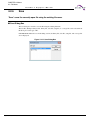
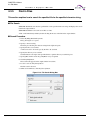
■ What is the SOFTUNE Workbench?
SOFTUNE Workbench is support software for developing programs for the F2MC-16 families of
microprocessors / microcontrollers.
It is a combination of a development manager, simulator debugger, emulator debugger, monitor debugger,
and an integrated development environment for efficient development.
■ Purpose of this Manual and Target Readers
This manual explains how to operate the SOFTUNE Workbench and design the product.
This manual is intended for engineers designing several kinds of products using SOFTUNE Workbench.
■ Trademarks
REALOS, SOFTUNE are trademark of Spansion LLC.
Microsoft and Windows are registered trademarks in the United States and other countries of United States
Microsoft Corporation.
Other company names and products names are trademarks or registered trademarks of their respective
companies.
■ Organization of Manual
This manual consists of five chapters.
CHAPTER 1 Outline of SOFTUNE Workbench
SOFUTUNE Workbench integrates language tools and debuggers into one to provide the integrated
development environment that totally supports processing from programming and debugging to creation
of data to be written to ROM. Language tools include a C compiler, assembler, and linkage tool, etc.
Debuggers are a simulator debugger, emulator debugger, and monitor debugger.
CHAPTER 2 Operation
This chapter explains the basic operation of SOFTUNE Workbench for each of the following items:
CHAPTER 3 Windows
This chapter explains SOFTUNE Workbench windows.
CHAPTER 4 Menus
This chapter explains the SOFTUNE Workbench menu configuration and the dialog boxes to be started
from each menu.
CHAPTER 5 Addin Module
This chapter explains SOFTUNE Workbench Addin module.
July 31, 2015, CM41-00312-9E
i
Soft ware
Support
Ma nual
APPENDIX
The Appendixes describes the register name, downloading monitor program, setting LAN interface,
setting USB interface, creating ROM on monitor debugger target, display on emulator, external I/F
DLL for simulator.
ii
CM41-00312-9E, July 31, 2015
Soft ware
Support
Ma nual
Reading This Manual
■ Configuration of Page
In each section of this manual, the summary about the section is described certainly, so you can grasp an
outline of this manual if only you read these summaries.
And the title of upper section is described in lower section, so you can grasp the position where you are
reading now.
July 31, 2015, CM41-00312-9E
iii
Soft ware
iv
Support
Ma nual
CM41-00312-9E, July 31, 2015
Soft ware
Support
Ma nual
CONTENTS
CHAPTER 1
1.1
1.2
1.3
Outline of SOFTUNE Workbench .............................................................. 1
Outline ................................................................................................................................................ 2
What is SOFTUNE Workbench? ........................................................................................................ 3
Procedure for Developing Programs with SOFTUNE Workbench ...................................................... 4
CHAPTER 2
Operation ..................................................................................................... 5
2.1
Parameters to be Entered from Dialog Boxes .................................................................................... 6
2.1.1
Data and Address Formulas (Numerical Constant) ....................................................................... 7
2.1.2
Data and Address Formulas (Symbols, Line Numbers, Character Constants) ............................. 9
2.1.3
Data and Address Formulas (Register Name, Flag Name) ......................................................... 11
2.1.4
Operators Usable in Data and Address Formulas ....................................................................... 12
2.1.5
Address Formula Specification .................................................................................................... 14
2.1.6
File Name Specification ............................................................................................................... 15
2.2
Starting and Terminating SOFTUNE Workbench ............................................................................. 16
2.3
Creating Project ................................................................................................................................ 17
2.4
Creating Workspace ......................................................................................................................... 20
2.5
Setting Project .................................................................................................................................. 22
2.6
Creating Files and Setting to Project ................................................................................................ 24
2.7
Definition of Subproject ..................................................................................................................... 25
2.8
Creation of Project Configuration ...................................................................................................... 26
2.9
Setting Tools ..................................................................................................................................... 28
2.10 Setting Linker Options ...................................................................................................................... 29
2.11 Make/Build ........................................................................................................................................ 31
2.11.1 Making or Building of Project ....................................................................................................... 32
2.12 Debugging ........................................................................................................................................ 33
2.13 Executing Debugging Only ............................................................................................................... 34
2.14 Reading SOFTUNE Project Files of Old Versions ............................................................................ 35
2.15 Moving Project Files ......................................................................................................................... 37
2.16 Useful Functions ............................................................................................................................... 38
CHAPTER 3
3.1
3.2
3.3
3.4
3.4.1
3.4.2
3.5
3.6
3.6.1
3.7
3.8
3.9
Windows .................................................................................................... 39
Window Configuration .......................................................................................................................
Tool Bar ............................................................................................................................................
Status Bar .........................................................................................................................................
Project Window .................................................................................................................................
SRC Tab ......................................................................................................................................
ABS Tab ......................................................................................................................................
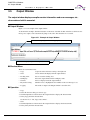
Output Window .................................................................................................................................
Edit Window (Standard Editor) .........................................................................................................
Setting Standard Editor ...............................................................................................................
Source Window .................................................................................................................................
Symbol Window ................................................................................................................................
Disassemble Window .......................................................................................................................
July 31, 2015, CM41-00312-9E
40
41
44
46
47
58
63
65
68
72
77
79
v
Soft ware
Support
Ma nual
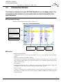
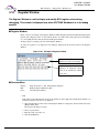
3.10 Register Window ............................................................................................................................... 82
3.10.1 Setting Register Display .............................................................................................................. 83
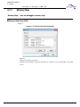
3.11 Memory Window ............................................................................................................................... 85
3.12 Local Variable Window ..................................................................................................................... 87
3.13 Watch Window .................................................................................................................................. 88
3.14 Trace Window ................................................................................................................................... 90
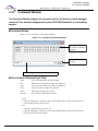
3.15 Command Window ........................................................................................................................... 92
3.15.1 Setting Character String Replacement ........................................................................................ 94
3.15.2 Logging ........................................................................................................................................ 97
3.16 Object Window .................................................................................................................................. 98
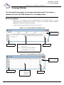
3.17 Coverage Window .......................................................................................................................... 100
3.18 Performance Window ..................................................................................................................... 102
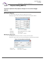
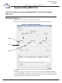
3.19 Sequence Window .......................................................................................................................... 109
3.19.1 Sequence Window (MB2141) .................................................................................................... 110
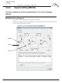
3.19.2 Sequence Window (MB2198) .................................................................................................... 112
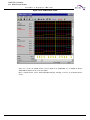
3.20 Real-time Memory Window ............................................................................................................. 118
3.21 RAM Checker Window .................................................................................................................... 120
3.21.1 Setup of the RAM Checker ........................................................................................................ 122
3.21.2 Start the RAM Checker Viewer .................................................................................................. 126
3.22 Terminal Window ............................................................................................................................ 128
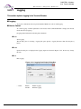
3.22.1 Logging ...................................................................................................................................... 130
CHAPTER 4
Menus ....................................................................................................... 131
4.1
Menu Configuration (Tree) ..............................................................................................................
4.2
File Menu ........................................................................................................................................
4.2.1
New ...........................................................................................................................................
4.2.2
Open ..........................................................................................................................................
4.2.3
Close .........................................................................................................................................
4.2.4
Open Workspace .......................................................................................................................
4.2.5
Close Workspace ......................................................................................................................
4.2.6
Save ..........................................................................................................................................
4.2.7
Save As .....................................................................................................................................
4.2.8
Save All .....................................................................................................................................
4.2.9
Print ...........................................................................................................................................
4.2.10 Recent Text File/Recent Workspace File ..................................................................................
4.2.11 Exit .............................................................................................................................................
4.3
Edit Menu ........................................................................................................................................
4.3.1
Undo, Redo ...............................................................................................................................
4.3.2
Cut, Copy, Paste, Delete ...........................................................................................................
4.3.3
Select All ....................................................................................................................................
4.3.4
Find/Replace .............................................................................................................................
4.3.5
Find in Files ...............................................................................................................................
4.3.6
Jump ..........................................................................................................................................
4.3.7
Bookmark ..................................................................................................................................
4.3.7.1 Bookmark - Source Window ...................................................................................................
4.3.7.2 Bookmark - Memory Window .................................................................................................
4.3.7.3 Bookmark - Edit Window ........................................................................................................
vi
132
135
136
145
148
149
150
151
152
154
155
156
157
158
159
160
162
163
165
166
167
168
171
173
CM41-00312-9E, July 31, 2015
Soft ware
Support
Ma nual
4.3.8
Previous Error, Next Error, Top of Error, Bottom of Error ..........................................................
4.3.9
Property .....................................................................................................................................
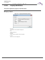
4.3.9.1 Property-Project Window ........................................................................................................
4.3.9.2 Property-Edit Window .............................................................................................................
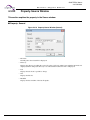
4.3.9.3 Property-Source Window ........................................................................................................
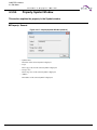
4.3.9.4 Property-Symbol Window .......................................................................................................
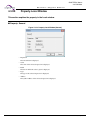
4.3.9.5 Property-Local Window ..........................................................................................................
4.3.9.6 Property-Watch Window .........................................................................................................
4.4
View Menu ......................................................................................................................................
4.4.1
Project/Output ............................................................................................................................
4.4.2
Symbol .......................................................................................................................................
4.4.3
Assembly ...................................................................................................................................
4.4.4
Register .....................................................................................................................................
4.4.5
Memory ......................................................................................................................................
4.4.6
Local ..........................................................................................................................................
4.4.7
Watch ........................................................................................................................................
4.4.8
Trace .........................................................................................................................................
4.4.8.1 Trace (Simulator Debugger) ...................................................................................................
4.4.8.2 Trace (Emulator Debugger [MB2141]) ...................................................................................
4.4.8.3 Trace (Emulator Debugger [MB2147-01]) ..............................................................................
4.4.8.4 Trace (Emulator Debugger [MB2147-05]) ..............................................................................
4.4.8.5 Trace (Emulator Debugger [MB2198]) ...................................................................................
4.4.8.6 Trace (Emulator Debugger [MB2100-01]) ..............................................................................
4.4.9
Command ..................................................................................................................................
4.4.10 Tool Bar, Status Bar, Tab ..........................................................................................................
4.4.11 Object ........................................................................................................................................
4.4.12 Coverage ...................................................................................................................................
4.4.13 Performance ..............................................................................................................................
4.4.13.1 Performance (Emulator Debugger [MB2141]) ........................................................................
4.4.13.2 Performance (Emulator Debugger [MB2147-01]) ...................................................................
4.4.13.3 Performance (Emulator Debugger [MB2198]) ........................................................................
4.4.13.4 Performance (Emulator Debugger [MB2100-01]) ...................................................................
4.4.14 Fonts ..........................................................................................................................................
4.4.15 Real-time Memory .....................................................................................................................
4.4.16 RAM Checker ............................................................................................................................
4.5
Project .............................................................................................................................................
4.5.1
Active Project .............................................................................................................................
4.5.2
Add Project ................................................................................................................................
4.5.2.1 Add Project - Create ...............................................................................................................
4.5.2.2 Add Project - Existing Project .................................................................................................
4.5.3
Add Member ..............................................................................................................................
4.5.3.1 Add Member - File ..................................................................................................................
4.5.3.2 Add Member - Directory .........................................................................................................
4.5.4
Setup Workspace ......................................................................................................................
4.5.5
Setup Project .............................................................................................................................
4.5.5.1 General ...................................................................................................................................
4.5.5.2 MCU .......................................................................................................................................
July 31, 2015, CM41-00312-9E
175
176
177
181
182
183
184
185
186
187
188
189
191
193
201
202
205
212
213
214
230
233
239
240
241
242
248
250
252
253
256
258
261
263
265
266
267
268
269
271
272
273
274
275
276
279
281
vii
Soft ware
Support
Ma nual
4.5.5.3 Setting C Compiler Options ....................................................................................................
4.5.5.4 Setting Assembler Options .....................................................................................................
4.5.5.5 Setting Linker Options ............................................................................................................
4.5.5.6 Section Disposition/Connection Specifying ............................................................................
4.5.5.7 Setting Librarian Options ........................................................................................................
4.5.5.8 Setting Converter Options ......................................................................................................
4.5.5.9 Setting Debug Options ...........................................................................................................
4.5.6
Setting Customize Build ............................................................................................................
4.5.7
Project Dependencies ...............................................................................................................
4.5.8
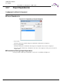
Project Configuration .................................................................................................................
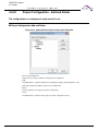
4.5.8.1 Project Configuration - Add and Delete ..................................................................................
4.5.8.2 Project Configuration - Configuration at Build ........................................................................
4.5.9
Include Dependencies ...............................................................................................................
4.5.10 Compile, Make, Build, and Stop ................................................................................................
4.6
Debug .............................................................................................................................................
4.6.1
Run ............................................................................................................................................
4.6.1.1 Power On Debug ....................................................................................................................
4.6.2
Abort ..........................................................................................................................................
4.6.2.1 Abort (Emulator Debugger [MB2100-01]) ...............................................................................
4.6.3
Reset MCU ................................................................................................................................
4.6.4
Break Point ................................................................................................................................
4.6.4.1 Code Break .............................................................................................................................
4.6.4.2 Data Break ..............................................................................................................................
4.6.4.3 Code Break - Hardware ..........................................................................................................
4.6.4.4 Code Break - Software ...........................................................................................................
4.6.4.5 Code Break - Hardware/Count ...............................................................................................
4.6.4.6 Code Break - Hardware/Data Watch ......................................................................................
4.6.4.7 Data Break ..............................................................................................................................
4.6.5
Event .........................................................................................................................................
4.6.5.1 Event List ................................................................................................................................
4.6.6
Sequence ..................................................................................................................................
4.6.6.1 Sequence Setting (MB2141) ..................................................................................................
4.6.6.2 Sequence Setting (MB2147-01) .............................................................................................
4.6.6.3 Sequence Setting (MB2198) ..................................................................................................
4.6.6.4 Sequence Setting (MB2100-01) .............................................................................................
4.6.7
Stack ..........................................................................................................................................
4.6.8
Time Measurement ....................................................................................................................
4.6.8.1 Measurement Unit During the Execution Time Measurement ................................................
4.6.9
Call ............................................................................................................................................
4.6.10 Clear Call ...................................................................................................................................
4.6.11 Vector ........................................................................................................................................
4.6.12 Load Target File ........................................................................................................................
4.6.13 Start Debug/End Debug ............................................................................................................
4.7
Setup ..............................................................................................................................................
4.7.1
Development .............................................................................................................................
4.7.2
Debug Environment ...................................................................................................................
4.7.2.1 I/O Port ...................................................................................................................................
viii
291
298
303
309
314
316
319
323
327
328
329
331
332
333
334
335
336
338
339
340
341
345
347
349
353
356
358
361
366
370
373
374
376
379
383
386
387
391
392
394
395
396
397
398
399
403
404
CM41-00312-9E, July 31, 2015
Soft ware
Support
Ma nual
4.7.2.2 Interrupt ..................................................................................................................................
4.7.2.3 Setting Debug Environment ....................................................................................................
4.7.2.4 Selection Debug Function ......................................................................................................
4.7.2.5 Setup Wizard ..........................................................................................................................
4.7.3
Memory Map ..............................................................................................................................
4.7.4
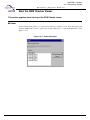
FLASH Memory Area Operation ................................................................................................
4.7.5
Tool ............................................................................................................................................
4.7.6
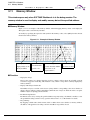
Keyboard ...................................................................................................................................
4.7.7
Editor .........................................................................................................................................
4.7.8
Error ...........................................................................................................................................
4.7.9
Tool Startup ...............................................................................................................................
4.8
Window ...........................................................................................................................................
4.8.1
Cascade, Vertical, Horizon ........................................................................................................
4.8.2
Split ............................................................................................................................................
4.8.3
Arrange Icons ............................................................................................................................
4.8.4
Refresh Window ........................................................................................................................
4.8.5
Refresh All Windows .................................................................................................................
4.8.6
Close All Windows .....................................................................................................................
4.9
Help ................................................................................................................................................
4.9.1
Help Topics ................................................................................................................................
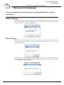
4.9.2
Support Information ...................................................................................................................
4.9.3
Version Information ...................................................................................................................
CHAPTER 5
408
409
438
439
449
457
459
462
464
466
468
469
470
471
472
473
474
475
476
477
478
479
Addin Module .......................................................................................... 483
5.1
Customize Bar ................................................................................................................................
5.1.1
What is Customize Bar? ............................................................................................................
5.1.2
Customize Bar Menu .................................................................................................................
5.1.3
Registering in the Customize Bar ..............................................................................................
5.1.3.1 Registering Batch File ............................................................................................................
5.1.3.2 Registering Workbench Menu ................................................................................................
5.1.3.3 Registering External Tool .......................................................................................................
5.1.4
Warning and Error Messages ....................................................................................................
5.1.5
Note ...........................................................................................................................................
484
485
487
488
492
494
496
498
500
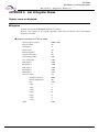
APPENDIX ......................................................................................................................... 501
APPENDIX A List of Register Names .........................................................................................................
APPENDIX B Downloading Monitor Program ............................................................................................
APPENDIX C Setting LAN Interface ...........................................................................................................
APPENDIX D Creating ROM on Monitor Debugger Target ........................................................................
APPENDIX E Display on Emulator .............................................................................................................
APPENDIX F Guide to Changing Function-call Interface ...........................................................................
APPENDIX G External I/F DLL for Simulator ..............................................................................................
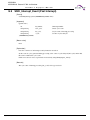
G.1 SSDI_Entry (Start) .........................................................................................................................
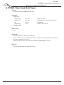
G.2 SSDI_Init (Initialize) ........................................................................................................................
G.3 SSDI_Ready (Ready) .....................................................................................................................
G.4 SSDI_End (End) .............................................................................................................................
G.5 SSDI_Reset_Event (Post Reset) ...................................................................................................
July 31, 2015, CM41-00312-9E
502
504
506
508
512
514
523
525
526
527
528
529
ix
Soft ware
Support
Ma nual
G.6 SSDI_Read_Event (Post Read) .....................................................................................................
G.7 SSDI_Write_Event (Post Write) .....................................................................................................
G.8 SSDI_Execute_Event (Post Execute Instruction) ..........................................................................
G.9 SSDI_Interrupt_Event (Post Interrupt) ...........................................................................................
G.10 SSDI_Timer_Event (Post Timer) ....................................................................................................
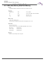
G.11 SSDI_Read_Memroy (Read from Memory) ...................................................................................
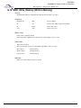
G.12 SSDI_Write_Memroy (Write to Memory) ........................................................................................
G.13 SSDI_Read_Register (Read from Register) ..................................................................................
G.14 SSDI_Write_Register (Write to Register) .......................................................................................
G.15 SSDI_Set_Interrupt (Set Interrupt Source) ....................................................................................
G.16 SSDI_Set_Timer (Set Timer) .........................................................................................................
G.17 SSDI_Request_Abort (Request Abort) ..........................................................................................
G.18 SSDI_Set_Area (Set Area) ............................................................................................................
G.19 SSDI_Clear_Cycle (Clear Cycle Count) .........................................................................................
G.20 SSDI_Execute_MCU (Execute Target Program) ...........................................................................
G.21 SSDI_GetCurrentExecuteAddr (Get the Address in Execution) ....................................................
APPENDIX H Sample Project for the Semihosting Function ......................................................................
APPENDIX I Major Changes .....................................................................................................................
530
531
532
533
534
535
536
537
538
539
540
541
542
543
544
545
546
550
INDEX................................................................................................................................... 551
x
CM41-00312-9E, July 31, 2015
Soft ware
Support
Ma nual
CHAPTER 1
Outline of SOFTUNE
Workbench
SOFUTUNE Workbench integrates language tools and
debuggers into one to provide the integrated
development environment that totally supports
processing from programming and debugging to
creation of data to be written to ROM. Language tools
include a C compiler, assembler, and linkage tool, etc.
Debuggers are a simulator debugger, emulator
debugger, and monitor debugger.
1.1 Outline
1.2 What is SOFTUNE Workbench?
1.3 Procedure for Developing Programs with SOFTUNE Workbench
July 31, 2015, CM41-00312-9E
1
CHAPTER 1 Outline of SOFTUNE Workbench
1.1 Outline
Soft ware
1.1
Support
Ma nual
Outline
This section gives an outline of the development tools integrated by SOFTUNE
Workbench.
■ Language Tools
In the past, language tools (e.g., C compiler, assembler, and linkage kit) were started and used from
command lines.
However, SOFTUNE Workbench can use these tools as they area. An option setting dialog box for each
tool opens, thereby enabling the easy use of the tools.
■ Debuggers
SOFTUNE Workbench has integrated the simulator debugger, emulator debugger, and monitor debugger
into one. The optimum debugger can be selected and used as required.
■ Others
Installing an REALOS configurator (option) enables cooperative operation without complicated setting.
2
CM41-00312-9E, July 31, 2015
CHAPTER 1 Outline of SOFTUNE Workbench
1.2 What is SOFTUNE Workbench?
Soft ware
1.2
Support
Ma nual
What is SOFTUNE Workbench?
This section explains the basic configuration of SOFTUNE Workbench.
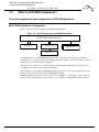
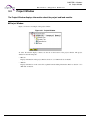
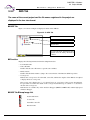
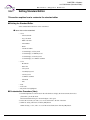
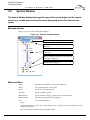
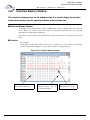
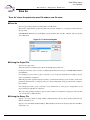
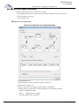
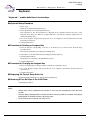
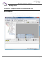
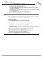
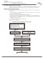
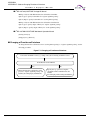
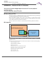
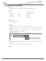
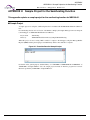
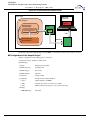
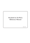
■ SOFTUNE Workbench Configuration
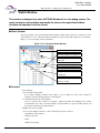
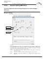
Figure 1.2-1 shows the basic configuration of SOFTUNE Workbench.
Figure 1.2-1 Basic Configuration of SOFTUNE Workbench
SOFTUNE Workbench body
Debugger part
Manager part
Configurator, etc
Language tool
As shown in Figure 1.2-1 SOFTUNE Workbench consists of three parts: body, debugger, and manager.
The debugger part contains the simulator debugger, emulator debugger, and monitor debugger. These
debuggers can be switched and used as required.
The manager part enables users to code and make programs without full knowledge of language tool (e.g.,
C compiler and assembler) start and option specification.
The configurator is not built into SOFTUNE Workbench because it is an option. Installing this option,
however, enables cooperative operation on SOFTUNE Workbench.
SOFTUNE Workbench manages all processing from programming to debugging in units of projects.
Projects contain all program files, options of tools (e.g., C compiler), and debugger environment setup, etc.
July 31, 2015, CM41-00312-9E
3
CHAPTER 1 Outline of SOFTUNE Workbench
1.3 Procedure for Developing Programs with SOFTUNE Workbench
Soft ware
1.3
Support
Ma nual
Procedure for Developing Programs with SOFTUNE
Workbench
The procedure for developing programs with SOFTUNE Workbench consists of the
followings:
1. Setting SOFTUNE Workbench operating conditions
2. Creating a project
3. Creating a program source and executing make/build
4. Using the debugger
■ Setting SOFTUNE Workbench Operating Conditions
When developing a program with SOFTUNE Workbench, first open the development environment setup
dialog box from the [Setup] - [Development] Menu and set environment variables and projects. For details
about how to set environment variables and projects, see Section "4.7.1 Development".
The environment variables set from this dialog box are referenced by language tools such as the C
compiler.
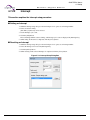
■ Creating a Project
Set information for the program to be developed in a project.
When developing a new project, open the new creation dialog box from the [File] - [New] Menu and select
[Workspace/Project File] from the dialog box. The new project creation dialog box opens.
When the project has already existed, the existing project file can be opened from the [File] - [Open
Workspace] Menu. When using the SOFTUNE V01 or V02 project file, see Section "2.14 Reading
SOFTUNE Project Files of Old Versions".
■ Creating a Program Source and Executing Make/Build
Open the new creation dialog box from the [File] - [New] Menu and select [Text File]. When the editor is
started, write the source program and save it to the file with the [File] - [Save As] Menu.
When a necessary source file is created, register it in the project with the [Project] - [Add Member] Menu.
When registering the source file in the project is completed, execute "make" with the [Project] - [Make]
Menu or execute "build" with the [Project] - [Build] Menu.
If a syntax error occurs during compilation or assembling, double-click the error display location in the
Output Window with the left button of the mouse. The program jumps to the line where the error occurred.
Correct the source file, and then reexecute the [Project] - [Make] Menu.
■ Using the Debugger
When a load module file is created, debugging can be begin.
4
CM41-00312-9E, July 31, 2015
Soft ware
Support
Ma nual
CHAPTER 2
Operation
This chapter explains the basic operation of SOFTUNE
Workbench for each of the following items:
2.1 Parameters to be Entered from Dialog Boxes
2.2 Starting and Terminating SOFTUNE Workbench
2.3 Creating Project
2.4 Creating Workspace
2.5 Setting Project
2.6 Creating Files and Setting to Project
2.7 Definition of Subproject
2.8 Creation of Project Configuration
2.9 Setting Tools
2.10 Setting Linker Options
2.11 Make/Build
2.12 Debugging
2.13 Executing Debugging Only
2.14 Reading SOFTUNE Project Files of Old Versions
2.15 Moving Project Files
2.16 Useful Functions
July 31, 2015, CM41-00312-9E
5
CHAPTER 2 Operation
2.1 Parameters to be Entered from Dialog Boxes
Soft ware
2.1
Support
Ma nual
Parameters to be Entered from Dialog Boxes
When key entry is requested from a dialog box, the following four elements can be
written as parameters:
• Data formula
• Address formula
• Identifier
• File name specification
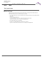
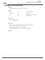
■ Data Formula
A data formula consists of a term and an operator. Data formulas comply with C language formulas.
Almost C language formulas are recognized. Some points (e.g, line number and register specification) are
extended. Operations involving floating-point numbers and character strings are not supported. The
overflows that occur during the operation are ignored. Zero division results in an error.
■ Address Formula
An address formula is an extension of the data formula; it represents a memory location. Like the data
formula, the address formula consists of a term and an operator. The terms and operators usable in address
formulas are the same as those in data formulas
■ Identifier
Alphabetic characters, numbers, and "_" can be used as identifiers. Each identifier must begin with a
character other than numbers. Uppercase characters are distinguished from lowercase characters or vice
versa.
■ File Name Specification
File name specification complies with Windows rules.
6
CM41-00312-9E, July 31, 2015
CHAPTER 2 Operation
2.1 Parameters to be Entered from Dialog Boxes
Soft ware
2.1.1
Support
Ma nual
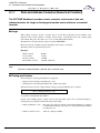
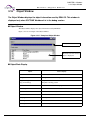
Data and Address Formulas (Numerical Constant)
The SOFTUNE Workbench provides numeric constants as the terms of data and
address formulas. An integer or floating-point number can be written as a numerical
constant.
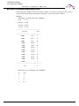
■ Integer
When writing an integer, specify a specifier (B', Q', D', H', 0x) representing the base number of the
numerical value. If the specifier is omitted, follow setting of the [Radix] tab in the "Setting debug
environment" dialog box. For details, see "4.7.2.3 Setting Debug Environment".
The numerical value representation range is from 0 to H'FFFFFFFF.
However, this range is further restricted, depending on the values to be entered.
The minus values are represented such as D'1.
(Example)
Binary constant:
B'1010
Octal constant:
Q'1267
Decimal constant:
D'1800
Hexadecimal constant:
H'12AF or 0x12AF
Note:
No blank is allowed between a specifier and a numerical value.
■ Floating-point Number
The following two floating-point numbers are supported.
• Single-precision floating-point number (S)....float
• Double-precision floating-point number (D)....double, long double
The internal format and size comply with the floating-point type handled by the C compiler.
[F'][-]{.d|d[.[d]]}[{S|D}[[+| -]d]]
"d" specifies an unsigned decimal number
Nearest value rounding applies to input values. If the represented value is not a normalized number, a
warning message is displayed and the following value is input:
• When an underflow occurs.... The values that can be represented as unnormalized numbers are changed
to unnormalized numbers. The values less than unnormalized numbers
are changed to 0.
• When an overflow occurs....
July 31, 2015, CM41-00312-9E
Values are changed to infinity.
7
CHAPTER 2 Operation
2.1 Parameters to be Entered from Dialog Boxes
Soft ware
Support
Ma nual
A floating-point number can also be specified in a hexadecimal number as follows:
H' hexadecimal - number [.{S|D}]
Note:
If S and D are omitted, D is assumed.
8
CM41-00312-9E, July 31, 2015
CHAPTER 2 Operation
2.1 Parameters to be Entered from Dialog Boxes
Soft ware
2.1.2
Support
Ma nual
Data and Address Formulas (Symbols, Line Numbers,
Character Constants)
The SOFTUNE Workbench provides symbols, line numbers, and character constants as
the terms of data and address formulas.
■ Symbol
The symbols used in the source program can be referenced as addresses; they have the type information
generated by the C compiler and other accessory information. The accessory information generated by the
assembler is label information. Each symbol consists of a module name, a function name, and a symbol
name. Specify these names as follows:
[[module-name][ \function-name]\] symbol-name
When the source program is written in the assembly language, module-name is the name written in the
operand of the ".PROGRAM" statement. When it is written in the C language, module-name is the name of
the source file to be compiled. Function-name is a function name written in the C language; it is valid only
when the source program is written in the C language.
To distinguish a global symbol from others, write it as "\symbol-name".
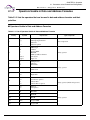
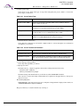
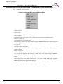
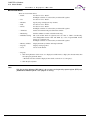
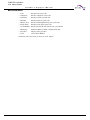
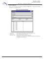
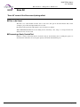
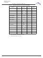
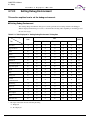
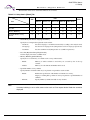
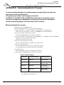
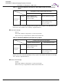
Table 2.1-1 shows symbol description.
No Japanese character strings can not be used for symbols.
Table 2.1-1 Symbol Cannot Description
Description
Contents
Symbol
Local symbol in function static symbol in module global symbol
Global symbol
\Symbol
Local symbol in the specified function in the current module
\function\symbol
Static symbol in the specified module or global symbol defined in the
specified module
Module\symbol
Local symbol in the specified function in the specified module
Module\function\symbol
Symbol in class (Valid for static)
Symbol in class function
July 31, 2015, CM41-00312-9E
9
CHAPTER 2 Operation
2.1 Parameters to be Entered from Dialog Boxes
Soft ware
Support
Ma nual
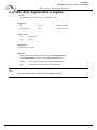
■ Line Number
The line numbers to be generated by the C compiler or assembler can be used to reference addresses. For
the C language, a line number indicates the starting address when one line is compiled.
[source file-name]$line-number
When referencing an address with a line number, prefix "$" to the line number. A line number can be
specified only in a decimal number. Specify the line number in the following format. If the extension of the
source file name is ".c", line number specification can be omitted. If the source file name is not
alphanumeric characters, enclose the line number in double quotes.
■ Character Constant
A character constant is the character value enclosed in a single quote; it cannot include a single quote and
"\". Instead of these characters (single quote and back slash), escape characters can be used as character
constants. Characters that can constitute character strings can be used as escape characters.
10
CM41-00312-9E, July 31, 2015
CHAPTER 2 Operation
2.1 Parameters to be Entered from Dialog Boxes
Soft ware
2.1.3
Support
Ma nual
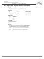
Data and Address Formulas (Register Name, Flag Name)
The SOFTUNE Workbench provides register and flag names as the terms of data and
address formulas.
■ Register Name, Flag Name
Register and flag names can be specified in data formulas; they represent the register values at that point of
time.
Specify the register name and flag name, following "%".
Usable register names differ for each MCU; see "APPENDIX A List of Register Names".
July 31, 2015, CM41-00312-9E
11
CHAPTER 2 Operation
2.1 Parameters to be Entered from Dialog Boxes
Soft ware
2.1.4
Support
Ma nual
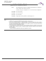
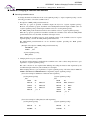
Operators Usable in Data and Address Formulas
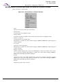
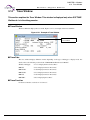
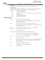
Table 2.1-2 lists the operators that can be used in data and address formulas and their
priorities.
■ Operators Usable in Data and Address Formulas
Table 2.1-2 List of Operators Usable in Data and Address Formulas
Priority
12
Symbol
Explanation
Type of operator
1
()
[]
.
->
Priority change
Subscript representation
Structure
Structure pointer
Linear expression
2
&
!
~
*
sizeof
(type)
Minus sign
Address
Logical NOT
Bit NOT
Memory indirect reference
Size (byte)
Type cast
Binary operator
3
*
/
%
Multiplication
Division
Remainder
4
+
-
Addition
Subtraction
5
<<
>>
Left shift
Right shift
6
<
<=
>
>=
Less than
Less than or equal to
Greater than
Greater than or equal to
7
==
!=
Equal to
Not equal to
8
&
Bit AND
9
^
Bit EOR
10
|
Bit OR
11
&&
Logical AND
12
||
Logical OR
Binary operator
Binary operator (Relational operator)
Binary operator
CM41-00312-9E, July 31, 2015
CHAPTER 2 Operation
2.1 Parameters to be Entered from Dialog Boxes
Soft ware
Support
Ma nual
Note:
When the comparison result is true, the relational operator becomes H'1. When false, it becomes
H'0. The SOFTUNE Workbench does not support the conditional operator (?:), comma operator (,),
increment operator (++) and decrement operator (--) of C language.
July 31, 2015, CM41-00312-9E
13
CHAPTER 2 Operation
2.1 Parameters to be Entered from Dialog Boxes
Soft ware
2.1.5
Support
Ma nual
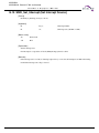
Address Formula Specification
Address formula specification is divided into the Full addressing and Address range
specification.
■ Full Addressing
The full addressing format is as follows:
32-bit-addressing
32-bit-addressing : Expression for addressing
■ Address Range Specification
Address range specification, representing a memory range, consists of two addressings; it has any of the
following two formats:
Addressing: addressing (from starting address to ending address)
Addressing: + offset (from starting address to (starting address + offset))
offset : Value relative to addressing (starting address)
■ Bit Addressing
The notation below is used to represent a bit address. Symbols for bit address attributes can be also used.
Bit addressing is valid when /BIT is specified in the command qualifier.
[addressing] : bit-offset
bit-offset: Value used to specify a bit position
When addressing is omitted, address 0 is assumed.
■ Bank Addressing
The bank addressing format is as follows:
bank-specification : offset-specification
bank-specification: Expression used to specify a bank address
offset-specification: Expression used to specify a 16-bit address
14
CM41-00312-9E, July 31, 2015
CHAPTER 2 Operation
2.1 Parameters to be Entered from Dialog Boxes
Soft ware
2.1.6
Support
Ma nual
File Name Specification
File name specification complies with Windows for host environment.
■ File Name Specification
[drive-name:] [directory-path-name] file-name [.extension]
When drive-name is omitted, the current drive is selected.
July 31, 2015, CM41-00312-9E
15
CHAPTER 2 Operation
2.2 Starting and Terminating SOFTUNE Workbench
Soft ware
2.2
Support
Ma nual
Starting and Terminating SOFTUNE Workbench
This section explains how to start and terminate SOFTUNE Workbench.
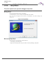
■ Starting and Terminating SOFTUNE Workbench
With SOFTUNE V3, to start SOFTUNE Workbench, double-click the [FFMC-16 Family Softune
Workbench] icon in the [Softune V3] group.
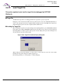
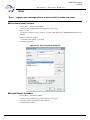
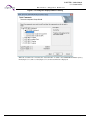
When this program is started for the first time with SOFTUNE Manager V01 or V02 installed, the dialog
box is displayed which asks whether or not to take over information for [Setting editor], [Setting tools], and
[Setting error jump] set in the previous version. To take over the information, click the [Yes] button. Not to
take over it, click the [No] button.
■ Terminating SOFTUNE Workbench
To terminate SOFTUNE Workbench, select [Exit] from the [File] Menu or click the x button above and on
the right of the window.
SOFTUNE Workbench cannot be terminated when compile/assemble, make, build, or tool is being
executed. Be sure to terminate SOFTUNE Workbench after compile/assemble, make, build, or tool has
been terminated or suspended.
16
CM41-00312-9E, July 31, 2015
CHAPTER 2 Operation
2.3 Creating Project
Soft ware
2.3
Support
Ma nual
Creating Project
This section explains how to create projects.
■ Project
A project is the unit for managing a source file used to create a target program and other information
together. A project file must be created to develop software with SOFTUNE Workbench.
■ Template Function
When you create a new project, you can create not only a brand new project but also create another project
based on an existing project. The function creating another project based on an existing project is called
template function.
The projects used for template function (called template projects) have same structure as those of existing
projects. Every existing project can be used as an template project.
● Items applied from the template project
When using template function, information of the template project and the members are fully applied.
However, the following items are not applied. Specify them again.
- Project name
- Directory for creating a project
● Location of the template project
For project template directory, see "4.7.1 Development". When the directory where the template project is
stored is specified for new project, the same source files are shared. If you do not share the same source
files, specify another directory for new project.
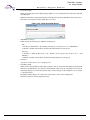
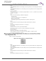
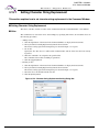
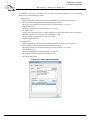
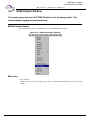
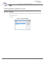
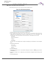
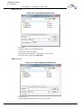
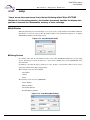
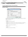
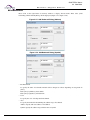
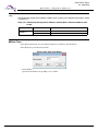
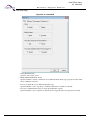
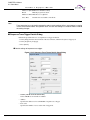
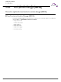
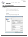
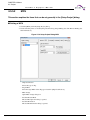
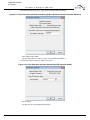
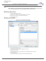
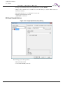
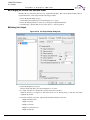
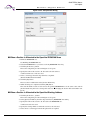
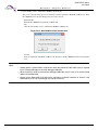
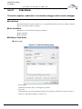
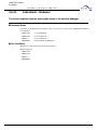
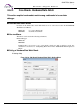
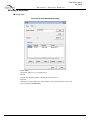
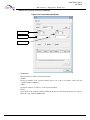
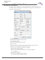
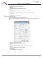
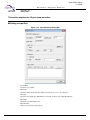
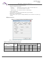
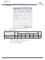
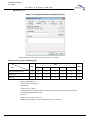
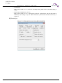
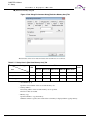
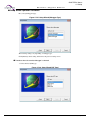
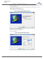
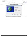
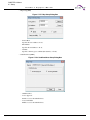
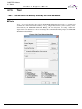
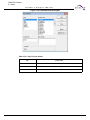
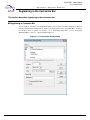
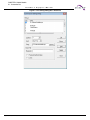
■ Creating a Project
Perform steps below to create a project. For details, see "4.2.1 New".
1. Select the [File]-[New] menu.
2. Select "Workspace/Project File" for [File type] on the creation dialog box.
3. Select the [Project] tab on the creation dialog box.
4. Select [Create New Workspace].
5. Select an option for creating project.
- When selecting [Blank project]
A new project is created without using template project.
Every option is set to default, and there is no project member.
- When selecting [Template]
A new project is created based on template project.
- When selecting [Browse for template]
Specify project template stored in other directories. After specifying template project, perform same
steps shown in "When selecting [Template]".
July 31, 2015, CM41-00312-9E
17
CHAPTER 2 Operation
2.3 Creating Project
Soft ware
Support
Ma nual
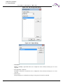
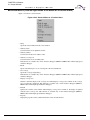
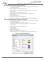
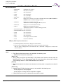
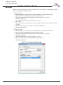
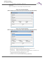
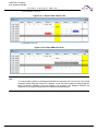
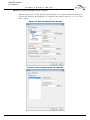
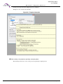
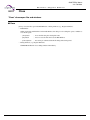
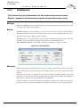
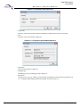
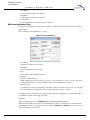
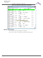
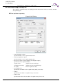
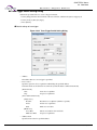
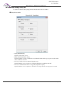
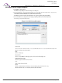
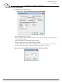
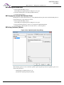
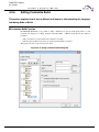
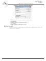
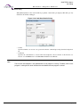
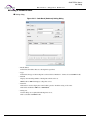
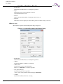
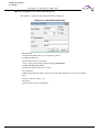
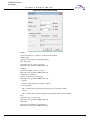
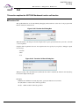
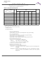
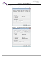
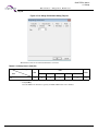
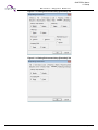
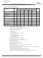
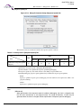
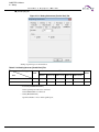
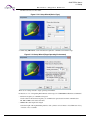
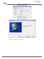
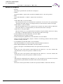
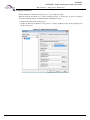
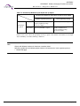
6. Select a project type.
Select [Project type], which is the type of target files managed by the project. Table 2.3-1 shows the
project types you can select.
Table 2.3-1 List of Project Type
Project type
Description
Absolute format (ABS)
Creates an executable load module which can be loaded into memory
whose address is resolved.
Relative format (REL)
Creates a load module which combines multiple object files. The address
resolution is not performed with the relative format (REL).
Library (LIB)
Creates a library file in which multiple object files are collected up (or
archived). Objects are not combined in the library (LIB).
REALOS (ABS)
Appears when REALOS is installed. Specify when using REALOS. For
details, see "SOFTUNE REALOS Configurator Manual".
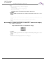
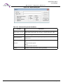
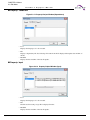
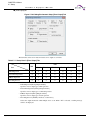
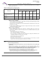
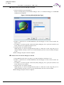
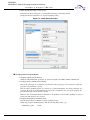
7. Select the function call interface.
Select [Function-call Interface], used with C compiler. Table 2.3-2 shows description for each function
call interface you can select.
Table 2.3-2 List of Function-call Interfaces
Function call interface
Description
Arguments by the stack
Passes function arguments by the stack. This is a default setting.
Arguments by registers
Passes selected function arguments by registers. This processing reduces
the code size and stack usage to improve the program execution speed.
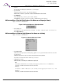
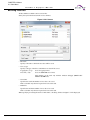
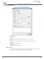
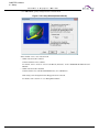
8. Select chip type and target MCU.
Select chip and target MCU you will use.
9. Input project name.
The input name (e.g. sample) is applied as shown below. Change the items if necessary.
- Target file name: sample.abs
- Directory: Default directory\sample
The initial setting of the default directory is the directory where SOFTUNE is installed.
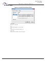
After a project is created, the setting of default directory is updated to the upper directory of the project
directory created.
10.Click the [OK] button.
When REALOS is selected as the project type, Configurator Setup Wizard is displayed. For details, see
"SOFTUNE REALOS Configurator Manual".
The project directory is created in the directory set in step 9.
18
CM41-00312-9E, July 31, 2015
CHAPTER 2 Operation
2.3 Creating Project
Soft ware
Support
Ma nual
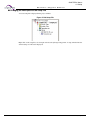
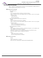
Subdirectories are also created in the project directory.
Debug :
Stores information for each project configuration. The default project configuration
name is "Debug" when creating a new project.
For details of the project configuration, see "2.8 Creation of Project Configuration".
Debug\ABS : Stores the target file.
Debug\OBJ : Stores the object file.
Debug\LST : Stores the list file.
Debug\OPT : Temporarily stores the option file to start the language tool.
Notes:
• If REALOS is not installed, REALOS project template cannot be used.
• When using a REALOS project as a template project, if the kernel header file name is same as
the name of the template project, exclude the file for copying. Create a new kernel header file by
performing make/build after project creation.
• If the teplate project of REALOS projectis used, the external reference symbol file name may be
changed. When a build error occurs, change the external reference symbol file name referred in
the user program.
* External reference symbol file name (e.g. R_project file name.h)
July 31, 2015, CM41-00312-9E
19
CHAPTER 2 Operation
2.4 Creating Workspace
Soft ware
2.4
Support
Ma nual
Creating Workspace
This section explains how to create a workspace.
■ Workspace
A workspace is the unit for managing projects together.
Workbench SOFTUNE manages created projects in the workspace. Be sure to create a workspace.
Multiple projects can be managed in a workspace.
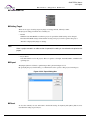
■ Creating Workspace
There are three methods to create workspaces.
● Creating workspace duing project creation
When creating a new project, you can create a workspace to store the project at the same time. In this case,
the workspace name and the directory name is set to the project name.
● Creating workspace when opening a project
When opening a project with [File]-[Open Workspace] menu, the workspace is created at the same time to
store the project. In this case, the workspace name and the directory name is set to the project name.
However, if a workspace file exists, the workspace file is opened instead of the project file.
● Creating empty workspace
An empty workspace is created without registering any project. A project must be registered separately. In
this case, the workspace can be created with the workspace name and the directory name which are not
used with any project in the workspace.
■ Creating Workspace Duing Project Creation
Same as the procedure for creating a project.
For details, see "2.3 Creating Project".
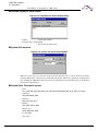
■ Creating Workspace when Opening a Project
Perform steps below to create a workspace. For details, see "4.2.2 Open".
1. Select the [File]-[Open Workspace] menu.
2. Select "Workspace/Project File" for [File type] on the open dialog box.
3. Select "Project File" for [File type] on the workspace open dialog box, and then select the project file.
The workspace is automatically created with the same name as that of the project.
20
CM41-00312-9E, July 31, 2015
CHAPTER 2 Operation
2.4 Creating Workspace
Soft ware
Support
Ma nual
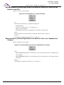
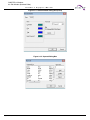
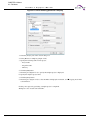
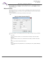
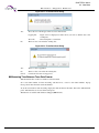
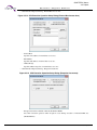
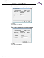
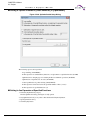
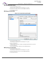
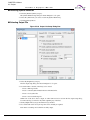
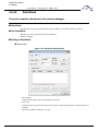
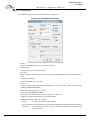
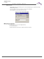
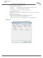
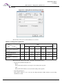
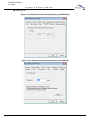
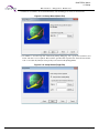
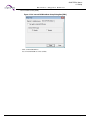
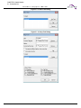
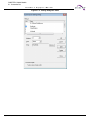
■ Creating Empty Workspace
Perform steps below to create a workspace. For details, see "4.2.1 New".
1. Select the [File]-[New] menu.
2. Select "Workspace/Project File" for [File type] on the creation dialog box.
3. Select the [Workspace] tab on the creation dialog box, and then select [Blank workspace] for workspace
type.
4. Input the workspace name. The input name is applied to the following settings.
- Workspace file name
- Workspace directory (can be changed)
5. Click the [OK] button.
An empty workspace is created in the set directory.
July 31, 2015, CM41-00312-9E
21
CHAPTER 2 Operation
2.5 Setting Project
Soft ware
2.5
Support
Ma nual
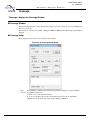
Setting Project
This section explains how to change the project in the workspace.
■ Adding Project
There are the following two methods to add a project to a workspace.
• Adding a new project to currently opened workspace
• Adding an existing project to currently opened workspace
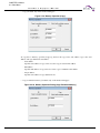
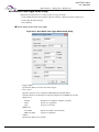
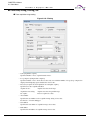
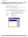
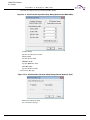
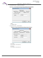
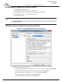
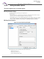
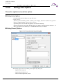
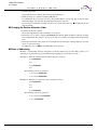
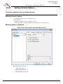
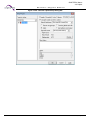
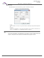
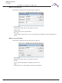
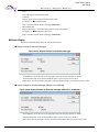
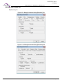
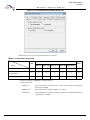
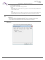
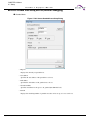
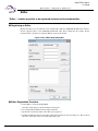
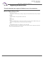
■ Adding a New Project to Currently Opened Workspace
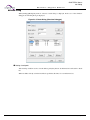
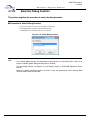
Perform steps below to add a project.
1. Select the [Project]-[Add Project]-[New] menu.
2. Place a check mark on [Add to the current workspace] on the creation dialog box.
3. Set the dependencies between projects. To set a project as a subproject of another project, place a check
mark on [Dependencies], and then select the project name in the list on the [Dependencies] dialog box.
For details of the subproject, see "2.7 Definition of Subproject".
After performing this step, see "■ Creating a Project" in "2.3 Creating Project".
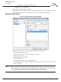
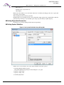
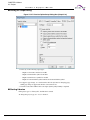
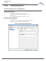
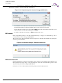
■ Adding a Currently Opened Project to Workspace
Perform steps below to add a project.
1. Select the [Project]-[Add Project]-[Project] menu.
2. Select the project to be added on the add project dialog box.
3. Set the dependencies between projects.
To set a project as a subproject of another project, place a check mark on [Dependencies], and then
select the project name in the list on the [Dependencies] dialog box. For details of the subproject, see
"2.7 Definition of Subproject".
4. Click the [Open] button.
The existing project is added to workspace.
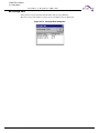
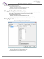
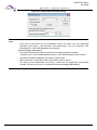
■ Setting the Active Project
When multiple projects are added to workspace, the target projects for the following operations must be
selected. The target project is called the active project.
• Make (*)
• Build (*)
• Compile/assemble (*)
• Start of debugging
• Dependency update (*)
*: The subproject of the active project is also influenced.
Set the active project as shown below.
1. Select the [Project]-[Active Project] menu.
2. Select the project for the active project.
22
CM41-00312-9E, July 31, 2015
CHAPTER 2 Operation
2.5 Setting Project
Soft ware
Support
Ma nual
The active project is set. The project added to the workspace at last is automatically set to the active
project.
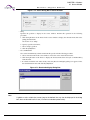
■ Deleting a Project Added to Workspace
Perform steps below to delete a project.
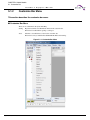
1. Specify the project to be deleted on the [SRC] tab of the project window. For details, see "3.4.1 SRC
Tab".
2. Select [Delete Project] from the shortcut menu.
The specified project is removed from the workspace; however, the project files are not deleted. If the
deleted project is a subproject of another project in the workspace, the dependencies between projects
are also deleted.
July 31, 2015, CM41-00312-9E
23
CHAPTER 2 Operation
2.6 Creating Files and Setting to Project
Soft ware
2.6
Support
Ma nual
Creating Files and Setting to Project
This section explains how to create new source files and how to set them to a project.
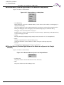
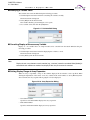
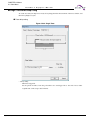
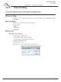
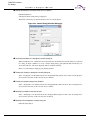
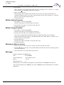
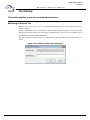
■ Creating New Source Files
1. Select the [File]-[New] menu.
- Select "Text file" for [File type] on the "New" dialog box, and then click the [OK] button.
2. Select the [File]-[Save as] menu.
- Select "Text file" for [File type] on the "Save as" dialog box, and then click the [OK] button.
A file dialog box appears to specify the directory and name for saving file. Select the directory for saving
file and specify the file name, and then click the [Save] button.
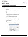
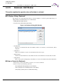
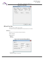
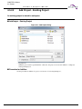
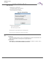
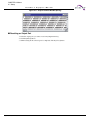
■ Adding the Created Files to the Project
Select the [File]-[Add Member to project]-[File] menu. The file dialog for selecting the file of addition is
displayed. Select the created source file, select the folder to be inserted to the SRC tab of the project
window, then click the [Open] button. The file is added to the project and the file name is displayed in the
folder specified on the SRC tab of the project window.
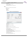
■ Adding the Created Files to the Project with Their Entire Directory
Select the [File]-[Add Member to project]-[Directory] menu. The dialog [Add Member - Directory] for
selecting the folder of addition is displayed. Select the directory where the created source file is stored,
select the folder to be inserted to the SRC tab of the project window, then click the [OK] button. The file is
added to the project, and the files and folders under the specified directory are displayed in the folder
specified on the SRC tab of the project window.
The type of files to be added can be limited with the setting of [File type] on the dialox box.
■ Deleting the Files Added to the Project
Select the file to be deleted on the SRC tab of the project window. Multiple files can be selected. Select
[Delete] from the shortcut menu.
The specified file is deleted from the project member; however, the file itself is not deleted.
Users cannot delete any file in the categories "Dependencies" and "Debug".
24
CM41-00312-9E, July 31, 2015
CHAPTER 2 Operation
2.7 Definition of Subproject
Soft ware
2.7
Support
Ma nual
Definition of Subproject
This section explains how to define a subproject.
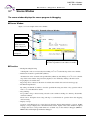
■ Definition of Subproject
The subproject is a project on which other projects depend.
SOFTUNE Workbench uses the following methods to define a subproject.
• Defining project as subproject in storing it
When created, a new project is defined as a subproject in another project. For the setting method, see
Section "2.5 Setting Project".
• Defining subproject between existing projects
A subproject is defined between projects in workspace.
Another project is defined as a subproject in the subproject in the parent project. Such a recurrent
definition that the parent project itself serves as a subproject is impossible.
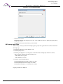
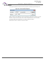
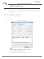
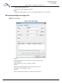
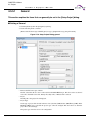
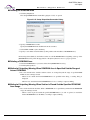
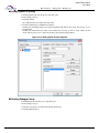
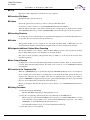
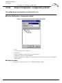
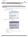
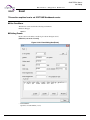
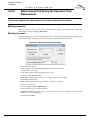
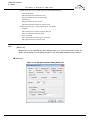
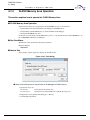
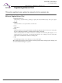
■ Defining Subproject Between Existing Projects
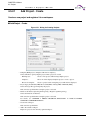
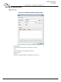
1. Select [Project]-[Project Dependence].
2. Select the parent project in which a subproject is defined.
When the [Project Dependence] dialog is opened, select the name of the parent project in which a
subproject is defined from the [Project Name] box.
3. Select the project that is defined as a subproject.
Check the project that is defined as a subproject from those in the [Dependent Project] list.
4. Click the [OK] button.
Select the [Project] - [Add Member] menu. The File dialog is opened to select the file to be added to the
member. Select the created source file, and click the [Open] button. The file is stored in the project and
its name is displayed in the source file category in the Project window.
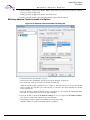
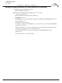
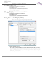
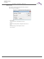
■ Deleting Subproject from Project
1. Select [Project]-[Project Dependence].
2. Select the parent project from which a subproject is deleted.
When the [Project Dependence] dialog is opened, select the name of the parent project from which a
subproject is deleted form the [Project Name] box.
3. Select the subproject to be deleted.
Deselect the subproject that is deleted from the [Dependent Project] list.
4. Click the [OK] button.
July 31, 2015, CM41-00312-9E
25
CHAPTER 2 Operation
2.8 Creation of Project Configuration
Soft ware
2.8
Support
Ma nual
Creation of Project Configuration
This section explains how to create a project configuration.
■ Creation of Project Configuration
The project configuration is a series of settings for specifying the characteristics of the target file. By
creating a new project configuration, two or more tool settings can be stored in the project.
When a new project is created, the project configuration is created under a default name of "Debug".
In SOFTUNE Workbench, the project configuration is created as follow.
• Creating project configuration on settings of existing project configuration
A new project configuration is created on the settings of the selected existing project configuration. In
the new project configuration, the same files as those in the original project configuration are always
used.
■ Creating Project Configuration on Settings of Existing Project Configuration
1. Select [Project]-[Project Configuration]-[Add and Delete].
2. Select the project to which a project configuration is added.
When the [Add and Delete Project] dialog is opened, select the project to which a project configuration
is added.
3. Click the [Add] button.
Click the [Add] button. The [Add Project Configuration] dialog is opened.
4. Enter the project configuration name.
Enter the unique name of a new project configuration. The characters that can be used to form a name
are "a to z", "A to Z", "0 to 9" and "_".
5. Select the project configuration to which settings are copied.
Select the initial settings of a project configuration to be added. The selected settings of the project
configuration (such as tool options, file configurations, and configurations of subprojects to be build)
are copied as they are.
6. Click the [OK] button.
Click the [OK] button in the [Add Project Configuration] dialog and the [OK] button in the [Add and
Delete Project Configuration] dialog.
■ Setting Active Project Configuration
The active project configuration is at default a project configuration that undergoes [Make], [Build],
[Compile/Assemble], [Start Debug], and [Include Dependence].
1. Select [Project]-[Project Configuration]-[Add and Delete].
2. Select the project configuration that is made active.
When the [Add and Delete Project] dialog is opened, select the name of the project configuration that is
made active.
3. Click the [Active] button.
Click the [Active] button. The specified configuration and its project become active.
4. Click the [OK] button.
26
CM41-00312-9E, July 31, 2015
CHAPTER 2 Operation
2.8 Creation of Project Configuration
Soft ware
Support
Ma nual
■ Deleting Specific Active Project Configuration from Project
1. Select [Project]-[Project Configuration]-[Add and Delete].
2. Select the project configuration that is deleted from the project.
When the [Add and Delete Project] dialog is opened, select the project configuration name to be deleted.
3. Click the [Delete] button.
Click the [Delete] button. The specified project configuration is deleted. When all project configurations
in a project are deleted, the project itself is also deleted.
4. Click the [OK] button.
July 31, 2015, CM41-00312-9E
27
CHAPTER 2 Operation
2.9 Setting Tools
Soft ware
2.9
Support
Ma nual
Setting Tools
When make or build is executed by SOFTUNE Workbench, appropriate options must be
set in such tools as a compiler, assembler and linker. Set these options as follows:
■ Select the [Project] [Setup Project] Menu
The [Set Project] dialog is opened. The option selected in the [Set Project] dialog box is applicable to two
or more projects. The applicable project configuration can be limited. For example, the settings of project
configurations A and B can be changed. The same setting can be also specified for all project
configurations.
Specify the project configuration in the [Setting Target] box, the project set in tree view, and select the tool
tab.
When the compiler, assembler and linker/librarian are selected, the category can be selected in the top tab
of the setting dialog box for each tool. After the drop-down list is opened, select a category. When a
category was selected, the contents in the display are changed and the options included in each category
can be set.
In most cases, compiler and assembler options need not be set except when output of list file and make or
build is executed under specific conditions. Set only linker options. For how to set linker options, see
Section "2.10 Setting Linker Options".
■ Click the [OK] Button to Complete Tool Setting
When setting all necessary tool options is completed, click the [OK] button. All the set options are
registered in the project; they become valid when make or build is executed.
Clicking the [Cancel] button cancels all the set options.
Note:
When the [Update] button is clicked during tool option setting, the previously set options cannot be
restored.
28
CM41-00312-9E, July 31, 2015
CHAPTER 2 Operation
2.10 Setting Linker Options
Soft ware
2.10
Support
Ma nual
Setting Linker Options
When creating a program with SOFTUNE Workbench, be sure to set a memory map with
a linker option.
■ Automatic Setting of Linker Options
In SOFTUNE Workbench, the following linker options are automatically set on the basis of information on
the MCU selected when a new project is created;
• Specify the internal ROM/RAM address of the MCU in the memory area option.
Internal ROM is output under an area name of "_INROMxx" and internal RAM under an area name of
"_INRAMxx" (where x is numbered consecutively starting with 01).
• Set the automatic disposition mode to mode 2 (optimum automatic disposition by linker).
When creating a program in a mode other than the single-chip mode or when customizing the
disposition of sections, set the [Disposition/Connection] option as the linker option.
■ Setting of Linker Options
In SOFTUNE Workbench, specifying memory mapping is basic to the disposition of each section in the
memory area. Therefore, set a memory area and set each section in the memory area.
■ Setting of Memory Area
Enter a ROM/RAM area name, start address and end address, select an area attribute (ROM or RAM), then
click the [Setup] button. This setting is displayed in the ROM/RAM area list. In the ROM/RAM area,
assign a unique ROM/RAM name so that it does not match other area names.
An easy program consists of a ROM area and a RAM area, but in a complicated program, several area may
be specified. The number of areas that can be set is not limited; set all the areas necessary to configure the
memory map of the program to be developed.
In Auto Disposition (Mode 2), the linker automatically allocates sections unspecified for allocation in a
ROM/RAM area.
The linker searches an available ROM/RAM area beginning at the top of the [ROM/RAM Area List]. Click
the [Up] button or the [Down] button to change the desired number.
■ Setting of the Sections
Selecting the area from the ROM/RAM area list and clicking the [Setup Section] button opens the [Setup
Section] dialog box, enabling the sections to be allocated to the selected area. When selecting an area, click
the start address of the area.
When the [Setup Section] dialog box opens, specify section names in the order the sections are allocated to
the area. Specify section names one by one. When section name specification is completed, click the
[Setup] button to register the section names in the section name list.
When execute make/built the sections are allocated to the area in the order the section names were
registered in the section name list.
When setting the sections to be allocated to one area is completed, click the [OK] button to return the linker
option setting dialog box. Also set other areas in the same way.
July 31, 2015, CM41-00312-9E
29
CHAPTER 2 Operation
2.10 Setting Linker Options
Soft ware
Support
Ma nual
Reference:
Allocating sections to several areas can be continuously set by changing ROM/RAM area name
display in the uppermost part of the [Setup Section] dialog box. The linker option setting dialog box
need not be returned each time sections are allocated to an area.
30
CM41-00312-9E, July 31, 2015
CHAPTER 2 Operation
2.11 Make/Build
Soft ware
2.11
Support
Ma nual
Make/Build
SOFTUNE Workbench can create a program in two methods: make and build.
■ Make
Compiles or assembles only the modified source file and then links all objects to the library to generate an
object program. SOFTUNE Workbench recognizes the dependency of the include files registered in the
[Dependencies] category of the SRC tab of Project Window to compile or assemble the source file.
Use the [Project]-[Make] Menu to execute make.
■ Build
Not only modified source file, but compiles or assembles all the source files registered in the project and
then links all objects to the library to generate a target file.
Use the [Project]-[Build] Menu to execute build.
■ Stop
Stop is the function that forcibly suspends processing during make, build, compilation, or assembling.
Execute stop with the [Project]-[Stop] Menu during make, build, compilation, or assembling.
July 31, 2015, CM41-00312-9E
31
CHAPTER 2 Operation
2.11 Make/Build
Soft ware
2.11.1
Support
Ma nual
Making or Building of Project
SOFTUNE Workbench enables making or building for each project configuration.
■ Making or Building of Project
[Make] or [Build] in the menu applies to the active configuration of an active project. If a subproject is
defined, priority is given to making or building of the subproject.
For details about how to change the active project and active configuration, see Section "2.5 Setting
Project" and Section "2.8 Creation of Project Configuration".
■ Making or Building Specified Project
Select the project to be made or built in the SRC tab of Project window. Select [Make] or [Build] in the
shortcut menu. The active configuration of the specified project is made or built. If a subproject is defined,
priority is given to making or building of the subproject.
■ Changing Subproject Configuration at Making or Building
1. Select [Project]-[Project Configuration]-[Configuration at Build].
2. Select the parent project and configuration.
When the [Set Configuration at Build] dialog is opened, select the project to be set from the [Project]
box. The configuration of a subproject to be made or built is displayed.
3. Select the configuration of a subproject.
Select the configuration to be made or built from [Configuration of Subproject at Make/Build].
4. Click the [OK] button.
Stop is the function that forcibly suspends processing during make, build, compilation, or assembling.
Execute stop with the [Project]-[Stop] Menu during make, build, compilation, or assembling.
32
CM41-00312-9E, July 31, 2015
CHAPTER 2 Operation
2.12 Debugging
Soft ware
2.12
Support
Ma nual
Debugging
The absolute file created as a result of normal termination of make/build can be
debugged immediately after SOFTUNE Workbench has migrated to the debug session.
■ Migrating SOFTUNE Workbench to Debug Session
To enable SOFTUNE Workbench to debug the absolute file, migrate it to the debug session.
To migrate SOFTUNE Workbench to the debug session, select [Start Debug] from the [Debug] Menu.
● First debugging after project creation
Setup Wizard for debuggers is started. Set the type of the debugger and others ("4.7.2.5 Setup Wizard").
● Second or subsequent debugging after project creation
Start SOFTUNE Workbench in the debugger mode that has been already set. To change the type of the
debugger, select the [Debug]-[End] Menu to terminate debugging once, and then change [Project]-[Project
Setup] Menu.
■ Automatic Downloading of Monitor Program
In case the following emulator is used, the debugging environment is determined from the emulator type
and version, etc., of the downloaded monitor program when proceeding to the debug session to download
the optimum monitor program automatically (APPENDIX B Downloading Monitor Program).
MB2147-01/MB2147-05/MB2198
■ Loading the Target Program
When SOFTUNE Workbench enters the debug session, select [Load target program] from the [Debug]
Menu to load the target program. The created program is loaded to the debugger and all debugging
preparations are completed now.
■ Operating the Debugger
For how to operate the debugger, see "CHAPTER 3 Windows" and "CHAPTER 4 Menus" in this manual.
For debugger commands and debugger output error messages, refer to the "SOFTUNE Workbench
Command Reference Manual".
For details of debugger functions, refer to "SOFTUNE Workbench User's Manual". Refer to "CHAPTER 1
Basic Functions" for details of MCU common functions. Refer to "CHAPTER 2 Dependence Functions"
for details of MCU chip dependence functions.
July 31, 2015, CM41-00312-9E
33
CHAPTER 2 Operation
2.13 Executing Debugging Only
Soft ware
2.13
Support
Ma nual
Executing Debugging Only
SOFTUNE Workbench can be used as the conventional debuggers.
■ Creating a Project
In SOFTUNE Workbench, projects are a basis of all work. This is not an exception also at debugging. For
this reason, executing debugging only requires the creation of a project for debugging.
First, create the project for debugging and the workspace which stores the project in the following procedure:
1. Select [New] from the [File] Menu.
2. Select [Project/Workspace File] from the file open dialog box.
- Select the absolute format (ABS) from the new creation dialog box for the project.
- Specify a project name.
- Specify a project directory.
- Select a target MCU name and chip type.
■ Setting of Workspace
Perform setting common to projects to be stored in workspace.
1. Select [Set Workspace] from the [Project] menu.
2. When the [Set Workspace] dialog is opened, perform the following settings
- Debug when workspace opened: Start debugging.
- Save setup information: Save.
■ Settings Related to the Debugger
1. Select [Project Setup] from the [Project] Menu.
2. When the setup dialog box opens, open the [Debug] tag and select [Setup] category:
3. Set a setup name.
A project name is set both in [Setup Name List] and [Valid Setup Name] as the default setup name.
Usually, setup names are identified by the type of the debugger to be used. However, if only one
debugger is used, the default name may be used as it is.
When the default name is used select the default name already set in [Setup Name List], then click the
[Change Setup] button. When another name is used, specify [Setup Name], then click the [Add Setup]
button.
■ Setup Wizard
Clicking the [Add Setup] or [Change Setup] button starts the Setup Wizard for debuggers. Once Setup
Wizard has been started, set items according to instructions from Setup Wizard. For how to set items with
Setup Wizard, see Section "4.7.2.5 Setup Wizard".
When all settings with Setup Wizard are completed, click the [Complete] button.
When the [Project Setup] dialog box is redisplayed, click the [OK] button.
When all the above steps are completed, save the project, then close it once.
■ Starting Debugging
When steps from [Creating a project] to [Setup Wizard] are complete, open the project. SOFTUNE
Workbench automatically migrates to the debug session, enabling the immediate start of debugging.
Select [Open] from the [File] menu and specify the load module file to load the target program.
34
CM41-00312-9E, July 31, 2015
CHAPTER 2 Operation
2.14 Reading SOFTUNE Project Files of Old Versions
Soft ware
2.14
Support
Ma nual
Reading SOFTUNE Project Files of Old Versions
The SOFTUNE project files of old versions can be read.
■ Procedure
● The project files created in SOFTUNE Workbench V3 version need the following setting.
1. Select [Open Workspace File] from the [File] menu.
2. Select 'Project file' from File Type and specify the project file made by the early version of SOFTUNE
Workbench. If the specified file is one made by the early version of Softune Workbench, a dialog asking
whether to convert the file to a workspace project format is opened.
[Yes] button:
The project file is converted and opened in the workspace project format.
[No] button:
The project file is not converted and is opened in the old project format. In this case,
some functions cannot be used. For details of functions that can be used in the old project
format, refer to Section "1.2 Management Function for Project" of "SOFTUNE
Workbench User's Manual".
[Cancel] button: Opening of the project file is cancelled.
● The project files created in SOFTUNE Manager V01/V02 version needs the following setting.
1. Select [Open Workspace File] from the [File] Menu.
2. Select 'Project file' from File Type and specify the project file made by SOFTUNE Manager. If the
specified file is one made by SOFTUNE Manager, a dialog asking whether to convert the file to a
workspace project format is opened.
Click the [Cancel] button to cancel opening of the project file.
3. Click the [OK] button to start conversion.
When you click the [Cancel] button, it cancels the opening of the project file.
4. When the New Project Creation Window opens, set the chip type and target MCU, then click the [OK]
button.
5. When conversion is completed, the dialog box showing the end of conversion opens. Click the [OK]
button to close the dialog box.
■ Backup File
In SOFTUNE Workbench, when a project file is converted to a workspace project format, a backup file is
made automatically. The extension of backup file varies with the type of project file. The method for
opening the backup project file is also different depending on the extension.
● SOFTUNE Workbench V3
Old project file (.prj) .p03
Old option data file (.dat) .d03
July 31, 2015, CM41-00312-9E
35
CHAPTER 2 Operation
2.14 Reading SOFTUNE Project Files of Old Versions
Soft ware
Support
Ma nual
● SOFTUNE Workbench V01/V02
Old project file (.prj) .V01
SOFTUNE Workbench V3 (.p03)
• Change the extension of the backup project file (.p03) and option data file (.d03) to '.prj' and '.dat,'
respectively.
SOFTUNE Manager V01/V02 (.v01)
• Change the extension of the backup project file (.v01) to '.prj.'
Notes:
• Tool options are not passed to projects of SOFTUNE Manager V01/V02. Reset these options
after read has terminated.
• Be sure to reset "User Include File Directory" set by "Set Environment Variable" of an old version
as the "Include Path" option of the C compiler or assembler. Also be sure to reset "Library File
Search Path" set by "Environment Variable Setup" of the old version as the "Library Search Path"
option of the linker.
• If the workspace file having the same name as that of the specified project file is in the same
directory, the workspace file is opened instead of the project file, and no project file is converted.
36
CM41-00312-9E, July 31, 2015
CHAPTER 2 Operation
2.15 Moving Project Files
Soft ware
2.15
Support
Ma nual
Moving Project Files
This section explains how to move a project file to another directory or a personal
computer.
■ Procedure
1. Set the path to the member stored in the project file to the relative path from the project file.
In SOFTUNE Workbench, files in the same drive as that of the project file are usually stored in the
relative path. To check whether the files are stored in the relative path, check File Property in the SRC
tab of Project window. For the file property, see Section "4.3.9 Property".
2. Set the path to the target file directory, object file directory and list file directory to the relative path
from the project file.
In SOFTUNE Workbench, when a new project is created, the output directory is set to the relative path
from the project file. To make a change and check, open the [Set Project] dialog. For details, see Section
"4.5.5 Setup Project".
3. Set the directories such as the include path and library path specified in the tool option to the relative
path or macro description.
For the macro description, see Section "1.11 Macro Descriptions Usable in Manager" of "SOFTUNE
Workbench User's Manual". For the tool option, see Section "4.5.5 Setup Project".
4. After the completion of the setting in steps 1 to 3, save the project.
5. Move the project file without changing the directory structure in steps 1 to 3.
July 31, 2015, CM41-00312-9E
37
CHAPTER 2 Operation
2.16 Useful Functions
Soft ware
2.16
Support
Ma nual
Useful Functions
This section explains some useful functions to use in the SOFTUNE Workbench.
■ Tab Display of the Windows
In the SOFTUNE Workbench, the displayed windows are tabbed.
This makes it easier to find the desired window quickly when multiple windows are displayed.
■ Drag & Drop Between Windows
SOFTUNE Workbench supports the drag & drop function between windows in the debugger. The
followings are the windows that currently support the drag & drop function.
Please refer to the description of each window for the operation by the drag & drop.
• Project window
• Source window
• Memory window
• Disassemble window
• Watch window
• Coverage window
• Real-time memory window
• RAM checker window
■ Confirmation of the Setting
SOFTUNE Workbench has various dialogs to set up functions. Each dialog requires you to click Set button
to take effect after you set up. If you attempt to close the dialog without clicking the [Set] button, a dialog
for confirmation will be displayed so that you won't fail to set up.
38
CM41-00312-9E, July 31, 2015
Soft ware
Support
Ma nual
CHAPTER 3
Windows
This chapter explains SOFTUNE Workbench windows.
3.1 Window Configuration
3.2 Tool Bar
3.3 Status Bar
3.4 Project Window
3.5 Output Window
3.6 Edit Window (Standard Editor)
3.7 Source Window
3.8 Symbol Window
3.9 Disassemble Window
3.10 Register Window
3.11 Memory Window
3.12 Local Variable Window
3.13 Watch Window
3.14 Trace Window
3.15 Command Window
3.16 Object Window
3.17 Coverage Window
3.18 Performance Window
3.19 Sequence Window
3.20 Real-time Memory Window
3.21 RAM Checker Window
3.22 Terminal Window
July 31, 2015, CM41-00312-9E
39
CHAPTER 3 Windows
3.1 Window Configuration
Soft ware
3.1
Support
Ma nual
Window Configuration
Each SOFTUNE Workbench window consists of a menu bar, tool bar, window screen,
and status bar. Menus are explained in "CHAPTER 4 Menus".
■ Main Window
Figure 3.1-1 shows the SOFTUNE Workbench Main Window. As shown in this figure, child windows
(e.g., project window and output window) and the tool bar can be shown with the Main Window and
displayed.
Figure 3.1-1 The SOFTUNE Workbench Main Menu
Tool Bar
Edit
Window
Project
Window
Output
Window
40
Status Bar
CM41-00312-9E, July 31, 2015
CHAPTER 3 Windows
3.2 Tool Bar
Soft ware
3.2
Support
Ma nual
Tool Bar
Command buttons to be used often are assigned to the tool bar for each group. The
groups that can be selected and the command buttons in the groups are shown below.
■ Common Bar
New
Open
Save
Cut
Copy
Paste
Undo
Redo
Jump to Next error
Jump to Previous error
Jump to Top error
Jump to Bottom error
Project window Docking
Output window Docking
Open Project window
Open Output window
■ Project Bar
The active project and its active configuration name are set and displayed.
■ Build Bar
Compile/Assembly
Make
Build
Stop Make/Build
■ Debug Bar
Go
Step In
Step Over
July 31, 2015, CM41-00312-9E
41
CHAPTER 3 Windows
3.2 Tool Bar
Soft ware
Support
Ma nual
Step Out
Run Until Cursor
Reset MCU
Abort
Breakpoint Set/Reset
Register window
Watch window
Memory window
Disassembly window
■ Flag Bar
Display and setting of MCU condition flag status
■ Trace
Display of the trace acquisition state and trace control while the user program is running
Update of the trace window
Updates the trace window. When the trace data is being acquired, the window is updated
after a forced stop.
Forced start of the trace acquisition
Forces to resume the acquisition of the trace data. It becomes valid only when the trace
acquisition has been forced to stop. It is only valid while running MCU. Forced stop of the
trace acquisition
Forced stop of the trace acquisition
Forces to stop the acquisition of the trace data. This doesn't stop any running user program,
except the trace acquisition. It is only valid while running MCU.
Trace acquisition state
Indicates the current trace acquisition state.
Tracing
: Trace data is being acquired.
Pause
: Trace acquisition is being paused.
End
: Trace acquisition has been terminated.
Trace buffer state
Indicates the current trace buffer state.
Data exist : Data exist in the trace buffer.
no data
: No data exist in the trace buffer.
Buffer full : Trace buffer is full.
42
CM41-00312-9E, July 31, 2015
CHAPTER 3 Windows
3.2 Tool Bar
Soft ware
Support
Ma nual
Note:
Trace tool bar becomes valid only when the debug function of MB2147-01 is in Trace Enhancement
mode. For more information, please refer to Section "2.3.1.6 Debug Function" in "SOFTUNE
Workbench User's Manual".
July 31, 2015, CM41-00312-9E
43
CHAPTER 3 Windows
3.3 Status Bar
Soft ware
3.3
Support
Ma nual
Status Bar
The current status of the SOFTUNE Workbench is displayed.
■ Status Bar
The status bar displays the current status of SOFTUNE Workbench.
The following information is displayed.
|----------------------------(1)----------------------------|
|--(2)--| |-----(3)-----|
|-(4)-| |--(5)--| |-(6)-| |-----(7)-----|
(1) Displays the following information.
When the cursor is placed over the menu: Description of the menu
When a user program has caused a break: Break factor (Only when the debugger is activated)
(2) Displays whether or not the debug session is being executed.
Debug session:
Displays "DEBUG"
Not debug session: Nothing is displayed
(3) Displays the MB number.
This item is displayed when the workspace (project) is opened.
Nothing is displayed, if workspace (project) is not open.
(4) Displays the current debugger type.
SIM:
Simulator debugger
EML:
Emulator debugger
MON:
Monitor debugger
(5) Displays whether or not the program is currently running.
For details about the sleep mode, stop mode, and watch mode, refer to the hardware manual of model to
be used.
Execute:
Indicates that the program is currently running.
Break:
Indicates that the program is inactive.
The following status is also displayed for the simulator debugger.
Stop:
Stop mode
Sleep:
Sleep mode
The following status is also displayed for the MB2100-01 emulator debugger.
44
Stop:
Stop mode
Timer:
Watch mode
Sleep:
Sleep mode
Halt:
CPU inactive status
Unknown:
Indicates that the CPU status cannot be detected.
For example, the system is in the power on debug mode.
CM41-00312-9E, July 31, 2015
CHAPTER 3 Windows
3.3 Status Bar
Soft ware
Support
Ma nual
(6) Displays the power on debug status.
Power on debug mode:
Displays "PON"
Not power on debug mode: Nothing is displayed
(7) Displays the current IP (instruction address).
This item is displayed when the debug session is being executed.
This item indicates the last branch PC value at the specified intervals when the program is running in
the MB2100-01 emulator debugger.
July 31, 2015, CM41-00312-9E
45
CHAPTER 3 Windows
3.4 Project Window
Soft ware
3.4
Support
Ma nual
Project Window
The Project Window displays information about the project and load module.
■ Project Window
Figure 3.4-1 shows an example of the project window.
Figure 3.4-1 Project Window
To select the window display contents, use the tab on the bottom of the project window. The project
window has the following tabs.
• SRC tab
Displays information on the project. Refer to Section "3.4.1 SRC Tab" tab for details.
• ABS tab
Displays information on the source file acquired from the debug information. Refer to Section "3.4.2
ABS Tab" for details.
46
CM41-00312-9E, July 31, 2015
CHAPTER 3 Windows
3.4 Project Window
Soft ware
3.4.1
Support
Ma nual
SRC Tab
The name of the current project and the file names registered in the project are
displayed in the tree view format.
■ SRC Tab
Figure 3.4-2 shows examples of displayed contents of the SRC tab.
Figure 3.4-2 SRC Tab
Workspace name
Target file name of project. It is followed by the project
name and active configuration name. The active project
is given in bold type.
Folder that can be deleted. When opened, the files and
folders stored are displayed. "Source Files" and "Include
Files" are created at default.
Library-file name
Source-file name
Include-file name
"Dependencies" category, the names of the files in which
dependencies are detected are displayed. The category
cannot be deleted.
File in the "Dependencies" category
"Debug" category. When opened, the setup name stored
is displayed. The category cannot be deleted.
Setup name
Subproject name
The files stored in project for making or building are
listed.
July 31, 2015, CM41-00312-9E
47
CHAPTER 3 Windows
3.4 Project Window
Soft ware
Support
Ma nual
■ Function
• Display the workspace name
• Display all projects stored in workspace
• Display the subproject
The subproject in the project is displayed below the parent project.
• Display of the project target file name
• Display of all the source file names registered in the project
When a source file name is double-clicked, the editor opens to enable the editing of the source file.
• Display of the include files that are in dependency
When an include file name is double-clicked, the editor opens to enable the editing of the include file.
• Displaying Debugger setup name
When the Debugger setup name is double-clicked, debugging is started based on the setup information.
• Drug and drop
The member in the SRC tab can be moved in the Project window and stored from the explorer.
■ SRC Tab Bitmap Image List
Workspace file name
Target file name
Subproject name
Folder
Category
C source file
C source file (not subject to making or building)
C source file in which individual options specified
C source file in which individual options specified (not subject to making or building)
Assembler source file
Assembler source file (not subject to making or building)
Assembler source file in which individual options specified
Assembler source file in which individual options specified (not subject to making or
building)
Include file
Include file (with dependence)
Library file
Library file (not subject to making or building)
Object file
Object file (not subject to making or building)
Relative format file
Relative format file (not subject to making or building)
48
CM41-00312-9E, July 31, 2015
CHAPTER 3 Windows
3.4 Project Window
Soft ware
Support
Ma nual
REALOS configuration file
Other user's registration files
Simulator Debugger setup name
Valid setup name (for Simulator Debugger)
Emulator Debugger setup name
Valid setup name (for Emulator Debugger)
Monitor Debugger setup name
Valid setup name (for Monitor Debugger)
■ Shortcut Menus (Click the Right Button of the Mouse on a Workspace Name)
Figure 3.4-3 shows a shortcut menu.
Figure 3.4-3 Shortcut Menu on a Workspace Name
• Add Project
When selected, the following two submenus are displayed.
- New
A new project is added to workspace (See Section "4.5.2 Add Project").
- Existing Project
An existing project is added to workspace (See Section "4.5.2 Add Project").
• Property
Information on the workspace file is displayed (See Section "4.3.9 Property").
■ Shortcut Menus (Click the Right Button of the Mouse on a Target Name)
Figure 3.4-4 shows a shortcut menu.
Figure 3.4-4 Shortcut Menu on a Target Name
• Set Active Project
The currently selected project is set in the active project in workspace.
July 31, 2015, CM41-00312-9E
49
CHAPTER 3 Windows
3.4 Project Window
Soft ware
Support
Ma nual
• Create New Folder
When selected, the [Create New Folder] dialog (Figure 3.4-5) is opened. Enter the folder name and click
the [OK] button.
When the folder name is entered, the folder is inserted into the hierarchy immediately below the project.
The folders are listed in the order in which they are created.
Figure 3.4-5 Create New Folder Dialog
• Add Member to Project
When selected, the following two submenus are displayed.
- File
A member is added in files to the currently selected project (See Section "4.5.3 Add Member").
At default, a member is inserted into the hierarchy immediately below the project.
- Directory
A member is added in directories to the currently selected project (See Section "4.5.3
Member").
At default, a member is inserted into the hierarchy immediately below the project.
Add
• Set Project
A project is set (See Section "4.5.5 Setup Project").
• Set Linkage Order
When selected, the [Set linkage Order] dialog (Figure 3.4-6) is opened. The files displayed in the [Link
Order] box are linked from top to down. To change the link order, select the configuration to be set from
the [Setting Target] box, followed by the file name, and use the [Up] or [Down] button to move the file
to a desired position.
The [Export] dialog (Figure 3.4-7) allows the current order to affect other configurations.
The files not subject to link are displayed in gray.
50
CM41-00312-9E, July 31, 2015
CHAPTER 3 Windows
3.4 Project Window
Soft ware
Support
Ma nual
Figure 3.4-6 Set Linkage Order Dialog
Figure 3.4-7 Export Dialog
• Make/Build
Making or building is performed in the active configuration of the currently selected project to create a
target file.
• Executing linker or librarian
The linker or librarian is started in the active configuration of the currently selected project to create a
target file.
• Delete Project
The specified project is deleted from workspace. The project file itself is not deleted.
July 31, 2015, CM41-00312-9E
51
CHAPTER 3 Windows
3.4 Project Window
Soft ware
Support
Ma nual
• Property
File information is displayed. (See Section "4.3.9 Property")
• Open List File
Select the list file you want to open, from the submenu.
If the list file you want to open is not created, no submenu item can be selected.
• Open HEX File
Select the HEX file you want to open, from the submenu.
If the HEX file you want to open is not created, no submenu item can be selected.
■ Shortcut Menu (Click the Right Button of the Mouse on a Subproject Name)
Figure 3.4-8 shows a shortcut menu.
Figure 3.4-8 Shortcut Menu on a Subproject Name
• Delete Subproject
The subproject in the specified project is deleted. To define a subproject again, see Section "4.5.7
Project Dependencies".
■ Shortcut Menus (Click the Right Button of the Mouse on a Folder)
Figure 3.4-9 shows a shortcut menu.
Figure 3.4-9 Shortcut Menu on a Folder
• Create New Folder
When selected, the [Create New Folder] dialog (Figure 3.4-5) is opened. Enter the folder name and click
the [OK] button.
When the folder name is entered, a folder is inserted into the selected folder.
The folders are listed in the order in which they are created.
• Add Member to Folder
When selected, the following two submenus are displayed:
- File
A member is added in files to the currently selected project (See Section "4.5.3 Add Member").
At default, a member is inserted into the selected folder.
- Directory
A member is added in directories to the currently selected project (See Section "4.5.3
Member").
At default, a member is inserted into the selected folder.
52
Add
CM41-00312-9E, July 31, 2015
CHAPTER 3 Windows
3.4 Project Window
Soft ware
Support
Ma nual
• Set
When selected, the following two submenus are displayed:
- Individual Setting
A project is set (See Section "4.5.5 Setup Project").
- Return to Common Setting
All individual options in the specified folder are returned to common options.
• Make/Build
Making or building is performed in the active configuration of the currently selected project to create a
target file.
• Delete
The selected folder and all files in the folder are deleted from the project. The files themselves are not
deleted.
If the files (RCF files) that cannot be deleted are included, the folder is not deleted.
• Property
Information on folders is displayed (see Section "4.3.9 Property").
■ Shortcut Menus (Click the Right Button of the Mouse on a "Dependencies" Category)
Figure 3.4-10 shows a shortcut menu.
Figure 3.4-10 Shortcut Menu on a "Dependencies" Category
• Make/Build
Making or building is performed in the active configuration of the currently selected project to create a
target file.
• Property
Information on folders is displayed (see Section "4.3.9 Property").
July 31, 2015, CM41-00312-9E
53
CHAPTER 3 Windows
3.4 Project Window
Soft ware
Support
Ma nual
■ Shortcut Menus (Click the Right Button of the Mouse on a "Debug" Category)
Figure 3.4-11 shows a shortcut menu.
Figure 3.4-11 Shortcut Menu on a "Debug" Category
• Add Setup
When selected, the following two submenus are displayed:
- New
When selected, the [Create New Setup] dialog (Figure 3.4-5) is opened. Enter the setup name and
click the [OK] button.
When the setup name is entered, the setup wizard is started. For details about the setup wizard, See
Section "4.7.2.5 Setup Wizard".
- Reference
When selected, the [Create New Setup] dialog (Figure 3.4-12) is opened. Enter the setup name and
click the [OK] button.
When the setup name is entered, the [Select File] dialog is opened. Select the file and click [Open]
button. Information is read from the specified file.
• Property
Information on folders is displayed (see Section "4.3.9 Property").
Figure 3.4-12 Create New Setup
■ Shortcut Menus (Click the Right Button of the Mouse on a Source File Name)
Figure 3.4-13 shows a shortcut menu.
Figure 3.4-13 Shortcut Menu on a Source File Name
54
CM41-00312-9E, July 31, 2015
CHAPTER 3 Windows
3.4 Project Window
Soft ware
Support
Ma nual
• Open
When SOFTUNE Workbench is in the debug session, the specified source file is displayed in the Source
Window.
When SOFTUNE Workbench is not in the debug session, the specified source file is displayed in the
edit window.
• Compile (Assemble)
The specified source file is automatically judged whether it is the C or assembler source and then
compiled or assembled.
• Set
When selected, the following two submenus are displayed:
- Individual Setting
A project is set (See Section "4.5.5 Setup Project").
- Return to Common Setting
All individual options in the specified folder are returned to common options.
• Delete
The specified file is released from the project member. The file itself is not deleted.
• Property
File information is displayed. (See Section "4.3.9 Property").
• Open List File
Select the list file you want to open, from the submenu.
If the list file you want to open is not created, no submenu item can be selected.
• Open Assemble file
This menu is opened when a C source file is selected.
Of the specified C source file, the assembler source file output by a compiler is opened.
No file can be selected when not compiled.
■ Shortcut Menus (Click the Right Button of the Mouse on an Include File and Other
User's Registration File)
Figure 3.4-14 shows a shortcut menu.
Figure 3.4-14 Shortcut Menu on a Include File Name
• Open
When SOFTUNE Workbench is in the debug session, the specified include file is displayed in the
Source Window.
When SOFTUNE Workbench is not in the debug session, the specified include file is displayed in the
edit window.
• Delete
The specified file is released from the project member. The file itself is not deleted.
• Property
File information is displayed. (See Section "4.3.9 Property").
July 31, 2015, CM41-00312-9E
55
CHAPTER 3 Windows
3.4 Project Window
Soft ware
Support
Ma nual
■ Shortcut Menus (Click the Right Button of the Mouse on Library File, Object File and
Relative Format File)
Figure 3.4-15 shows a shortcut menu.
Figure 3.4-15 Shortcut Menu on a Library File Name
• Set
When selected, the following two submenus are displayed:
- Individual Setting
A project is set (See Section "4.5.5 Setup Project").
- Return to Common Setting
All individual options in the specified folder are returned to common options.
• Delete
The specified file is released from the project member. The file itself is not deleted.
• Property
File information is displayed. (See Section "4.3.9 Property").
■ Shortcut Menus (Click the Right Button of the Mouse on a File in the "Dependencies"
Category)
Figure 3.4-16 shows a shortcut menu.
Figure 3.4-16 Shortcut Menu on a File in the "Dependencies" Category
• Open
- When SOFTUNE Workbench is in the debug session, the specified source file is displayed in the
Source Window.
- When SOFTUNE Workbench is not in the debug session, the specified source file is displayed in the
edit window.
• Property
File information is displayed. (See Section "4.3.9 Property").
56
CM41-00312-9E, July 31, 2015
CHAPTER 3 Windows
3.4 Project Window
Soft ware
Support
Ma nual
■ Shortcut Menu (Click the Right Button of the Mouse on Setup Name)
Figure 3.4-17 shows a shortcut menu.
Figure 3.4-17 Shortcut Menu on a Setup Name
• Start /End Debug
During debugging session, the confirmation dialog "Is the current session ended to start debugging?" is
displayed. Select [YES].
The current debugging is ended, and then debugging is started based on the specified setup information.
During non-debugging session, debugging is started without displaying the confirmation dialog.
Debugging can be started only in the active project.
In debug session, only the valid setup changes from [Start Debug] to [End Debug]. When [End Debug]
is selected, debugging is ended.
• Change
The setup wizard for changing the setup setting is started (see Section "4.7.2.5 Setup Wizard").
• Delete
Debugger setup information is deleted from the project.
Valid setup information cannot be deleted. To delete, change the valid setup temporarily.
• Property
Setup information is displayed (see Section "4.3.9 Property").
■ Shortcut Menus (Click the Right Button of the Mouse on a Space in the Project
Window)
Figure 3.4-18 shows a shortcut menu.
Figure 3.4-18 Shortcut Menu on Space in the Project Window
• Docking View
The project window is docked with the frame in the check status.
• Hide
The project window enters the nondisplay status.
July 31, 2015, CM41-00312-9E
57
CHAPTER 3 Windows
3.4 Project Window
Soft ware
3.4.2
Support
Ma nual
ABS Tab
The name of the current project and the file names registered in the project are
displayed in the tree view format.
■ ABS Tab
Figure 3.4-19 shows examples of displayed contents of the ABS tab.
Figure 3.4-19 ABS Tab
Load module name
Source file name
Function name
The source file name and function name
acquired from the debug information
are listed.
■ Function
Display the following information form the debug information.
• Load module name
• Source filename
Double-click the source file name to open the source window.
• Function name
Double-click the function name to jump to the source window of the function definition position.
• Coverage rate
Indicates the coverage rates of load module, source file, and function. Update of the ABS tab is required
to display the latest coverage rate.
The coverage rate is displayed as "(--%)" when all areas are out of range of the coverage measurement.
If a part of the area falls in the outside of the coverage measurement rage, an asterisk "*" is attached to
the end of the coverage rate.
This function is available only on the emulator debuggers (MB2141, MB2147-01) and the high-speed
simulator debugger.
■ ABS Tab Bitmap Image List
Load module name
C source file
Assembler source file
Function name
58
CM41-00312-9E, July 31, 2015
CHAPTER 3 Windows
3.4 Project Window
Soft ware
Support
Ma nual
■ Shortcut Menus (Click the Right Button of the Mouse on a Load Module Name)
Figure 3.4-20 shows a shortcut menu.
Figure 3.4-20 Shortcut Menu on a Load Module Name
• Open
Cannot be selected.
• Order by name
Sort items in the tree in alphabetical order.
• Order by address
Sort functions in the tree in address order, and sort other items in the tree in alphabetical order.
• Order by coverage rate
Sort items in the tree in ascending order.
This function is available only on the emulator debuggers (MB2141, MB2147-01) and the high-speed
simulator debugger.
• Set coverage
Opens the coverage setting dialog.
This function is available only on the emulator debuggers (MB2141, MB2147-01) and the high-speed
simulator debugger.
• Display coverage rate
Switches on/off the display of the coverage rate. When Display coverage rate is turned on, the coverage
rate of each item is displayed. This function is available only on the emulator debuggers (MB2141,
MB2147-01) and the high-speed simulator debugger.
• Refresh
Updates the contents of the window. When Display coverage rate is turned on, the display is updated
with the latest coverage rate. This function is available only on the emulator debuggers (MB2141,
MB2147-01) and the high-speed simulator debugger.
• Property
Information on the load module file is displayed (See Section "4.3.9 Property").
July 31, 2015, CM41-00312-9E
59
CHAPTER 3 Windows
3.4 Project Window
Soft ware
Support
Ma nual
■ Shortcut Menus (Click the Right Button of the Mouse on a Source File Name)
Figure 3.4-21 shows a shortcut menu.
Figure 3.4-21 Shortcut Menu on a Source File Name
• Open
Opens the selected source file in the source window.
• Order by name
Sort items in the tree in alphabetical order.
• Order by address
Sort functions in the tree in address order, and sort other items in the tree in alphabetical order.
• Order by coverage rate
Sort items in the tree in ascending order.
This function is available only on the emulator debuggers (MB2141, MB2147-01) and the high-speed
simulator debugger.
• Set coverage
Opens the coverage setting dialog.
This function is available only on the emulator debuggers (MB2141, MB2147-01) and the high-speed
simulator debugger.
• Display coverage rate
Switches on/off the display of the coverage rate. When Display coverage rate is turned on, the coverage
rate of each item is displayed. This function is available only on the emulator debuggers (MB2141,
MB2147-01) and the high-speed simulator debugger.
• Refresh
Updates the contents of the window. When Display coverage rate is turned on, the display is updated
with the latest coverage rate. This function is available only on the emulator debuggers (MB2141,
MB2147-01) and the high-speed simulator debugger.
• Property
Display the properties of the source file.
60
CM41-00312-9E, July 31, 2015
CHAPTER 3 Windows
3.4 Project Window
Soft ware
Support
Ma nual
■ Shortcut Menus (Click the Right Button of the Mouse on a Function Name)
Figure 3.4-22 shows a shortcut menu.
Figure 3.4-22 Shortcut Menu on a Function Name
• Jump
Opens the selected function in the source window.
• Order by name
Sort items in the tree in alphabetical order.
• Order by address
Sort functions in the tree in address order.
• Order by coverage rate
Sort items in the tree in ascending order.
This function is available only on the emulator debuggers (MB2141, MB2147-01) and the high-speed
simulator debugger.
• Break
Opens a break dialog box to set a break point at the selected function.
• Set coverage
Opens the coverage setting dialog.
This function is available only on the emulator debuggers (MB2141, MB2147-01) and the high-speed
simulator debugger.
• Display coverage rate
Switches on/off the display of the coverage rate. When Display coverage rate is turned on, the coverage
rate of each item is displayed. This function is available only on the emulator debuggers (MB2141,
MB2147-01) and the high-speed simulator debugger.
• Refresh
Updates the contents of the window. When Display coverage rate is turned on, the display is updated
with the latest coverage rate. This function is available only on the emulator debuggers (MB2141,
MB2147-01) and the high-speed simulator debugger.
• Property
Display the properties of the symbol information of the selected function.
July 31, 2015, CM41-00312-9E
61
CHAPTER 3 Windows
3.4 Project Window
Soft ware
Support
Ma nual
■ Shortcut Menu (Click the Right Button of the Mouse on Space in the Project Window)
Figure 3.4-23 shows a shortcut menu.
Figure 3.4-23 Shortcut Menu on Space in the Project Window
• Docking View
The project window is docked with the frame in the check status.
• Hide
The project window enters the nondisplay status.
62
CM41-00312-9E, July 31, 2015
CHAPTER 3 Windows
3.5 Output Window
Soft ware
3.5
Support
Ma nual
Output Window
The output window displays compiler version information and error messages, etc.,
when make or build is executed.
■ Output Window
Figure 3.5-1 is an example of the output window.
As shown in this example, when the left button of the mouse is double-clicked on the line to which an error
message was output, control automatically jumps to the source line where the error occurred.
Figure 3.5-1 Example of Output Window
Tool start message (e.g., version and copyright)
Tool error message (example of C compiler)
■ Shortcut Menu
There are seven menus below:
• Copy:
Copies the selected character string to the clipboard.
• Clear:
Clears all the items displayed in the output window.
• Docking View:
Sets or resets the docking view.
• Nondisplay:
Places the output window in the nondisplay status.
• Set Font:
Selects a display font in the output window.
• Keyword Coloring:
Whether or not to highlight the error number of the error message is set.
• Logging:
The result of output to the Output window is stored in a file.
■ Operation
• Copy
1. Select the character string you want to copy.
2. Click the right button of the mouse in the output window to display the shortcut menu.
3. Select [Copy] from the shortcut menu.
See Section "4.3.2 Cut, Copy, Paste, Delete".
• Clear
1. Click the right button of the mouse in the output window to displays the shortcut menu.
2. Select [Clear] from the shortcut menu.
July 31, 2015, CM41-00312-9E
63
CHAPTER 3 Windows
3.5 Output Window
Soft ware
Support
Ma nual
• Docking View
1. Click the right button of the mouse in the output window to display the shortcut menu.
2. Select [Docking View] from the shortcut menu.
The output window is docked with the frame in the check status.
• Display
1. Click the right button of the mouse in the output window to display the shortcut menu.
2. Select [Nondisplay] from the shortcut menu.
- The output window enters the nondisplay status.
• Set Font
1. Click the right button of the mouse in the output window to display the shortcut menu.
Select [Set Font] from the shortcut menu.
The font selection dialog box (Figure 3.5-2) opens.
2. Select [Font] and [Size], then click the [OK] button.
Figure 3.5-2 Font Setting Dialog Box
• Highlight Keyword
1. Display the shortcut menu by clicking the right button on the Output window.
2. Select [Keyword Coloring].
In the check state, the keyword (error number) of the error message is displayed in red.
• Logging
1. Display the shortcut menu by clicking the right button on the Output window.
2. Select [Logging]-[Start] and then specify the file name of the record target file.
The result of output to the Output window is recorded in the specified file.
3. To suspend logging, select [Logging]-[Record] and uncheck the checkbox.
Logging is restarted again when the checkbox is checked.
4. To stop logging, select [Logging]-[Termination].
64
CM41-00312-9E, July 31, 2015
CHAPTER 3 Windows
3.6 Edit Window (Standard Editor)
Soft ware
3.6
Support
Ma nual
Edit Window (Standard Editor)
The edit window is used to display and edit a source file and document file, etc.
■ Edit Window
An example of the edit window docked with the Main Window is given in Figure 3.6-1.
As shown in this example, the edit window docked with the Main Window can be displayed only when the
standard editor built into SOFTUNE Workbench is in use.
SOFTUNE Workbench can register and use any external editor. In this case, however, the edit window is
not treated as a SOFTUNE Workbench screen.
Figure 3.6-1 Example of Edit Window
Ruler
Line number display
Text editing area
Line selection field
When a read-only file is opened, [Protect] is displayed.
When the Caps key is locked, [CAP] is displayed.
When SOFTUNE Workbench is in the character overwrite editing
mode, [Overwrite] is displayed.
The cursor position is displayed in "line:column".
■ Shortcut Menu
• Source Window:
Opens the Source Window.
• Undo:
Undoes the last editing.
• Redo:
Redoes the canceled editing.
• Cut:
Moves the selected character string to the clipboard.
July 31, 2015, CM41-00312-9E
65
CHAPTER 3 Windows
3.6 Edit Window (Standard Editor)
Soft ware
Support
Ma nual
• Copy:
Copies the selected character string to the clipboard.
• Paste:
Pastes the character string in the clipboard to the cursor position.
• Delete:
Deletes the selected character string.
• Select All:
Selects all characters in the buffer.
• Print:
Prints the file.
• Add to Project:
Adds the file being edited to the active project.
• Find:
Opens the character string find dialog box.
• Replace:
Opens the character string replacement dialog box.
• Search File:
See Section "4.3.5 Find in Files".
• Jump to Specified Line: Opens the jump line number specification dialog box.
• Bookmark:
See Section "4.3.7 Bookmark".
• Set Standard Editor:
See Section "3.6.1 Setting Standard Editor".
• Status Bar:
Switches status bar display for each window.
• Property:
Display file information (properties).
• Source Window
Click the right button of the mouse to display the shortcut menu, then select [Source Window] from the
menu.
- When SOFTUNE Workbench is in the debug session, the Source Window is displayed. See Section
"3.7 Source Window".
When SOFTUNE Workbench is not in the debug session, this menu cannot be selected.
• Undo
Click the right button of the mouse to display the shortcut menu, then select [Undo] from the menu.
- SOFTUNE Workbench cancels the last editing and undoes the status before the editing. See Section
"4.3.1 Undo, Redo".
• Redo
Click the right button of the mouse to display the shortcut menu, then select [Redo] from the menu.
SOFTUNE Workbench cancels the cancel of the last editing.
• Cut
1. Select the character string you want to cut.
2. Click the right button of the mouse to display the shortcut menu, then select [Move] from the menu.
- SOFTUNE Workbench deletes the selected character string from the edit window and moves it to the
clipboard. See Section "4.3.2 Cut, Copy, Paste, Delete".
• Copy
1. Select the character string you want to copy.
2. Click the right button of the mouse to display the shortcut menu, then select [Copy] from the menu.
- SOFTUNE Workbench copies the selected character string to the clipboard. See Section "4.3.2 Cut,
Copy, Paste, Delete".
• Paste
1. Move the cursor to the position into which the character string is to be inserted.
2. Click the right button of the mouse to display the shortcut menu, then select [Paste] from the menu.
- SOFTUNE Workbench inserts the character string in the clipboard into the cursor position. See
Section "4.3.2 Cut, Copy, Paste, Delete".
66
CM41-00312-9E, July 31, 2015
CHAPTER 3 Windows
3.6 Edit Window (Standard Editor)
Soft ware
Support
Ma nual
• Delete
1. Select the character string you want to delete.
2. Click the right button of the mouse to display the shortcut menu, then select [Delete] from the menu.
- SOFTUNE Workbench deletes the selected character string. See Section "4.3.2 Cut, Copy, Paste,
Delete".
• Select All
Click the right button of the mouse to display the shortcut menu, then select [All select] from the menu.
- SOFTUNE Workbench selects all the texts in the edit window and displays them in reverse video.
See Section "4.3.3 Select All".
• Print
Click the right button of the mouse to display the shortcut menu, then select [Print] from the menu.
- The print dialog box opens. See Section "4.2.9 Print".
• Add to Project
Click the right button of the mouse to display the shortcut menu, then select [Add to Project] from the
menu.
- SOFTUNE Workbench adds the file being edited to the project.
• Find/Replace
Click the right button of the mouse to display the shortcut menu, then select [Find] or [Replace] from
the menu.
- SOFTUNE Workbench sets the clipboard character string in [Find What] and opens the Find or
Replace dialog box. See Section "4.3.4 Find/Replace".
• Find in Files
Click the right button of the mouse to display the shortcut menu, then select [Find in Files] from the
menu.
- SOFTUNE Workbench sets the clipboard character string in [Find what] and opens the Find in Files
dialog box. See Section "4.3.5 Find in Files".
• Jump to Specified Line
1. Click the right button of the mouse to display the shortcut menu, then select [Jump to Specified Line]
from the menu.
- The dialog box for specifying the jump destination line opens. See Section "4.3.6 Jump".
2. Set the jump destination line number.
3. Click the [OK] button.
• Status Bar
Status Bar switches status bar display and non-display for each Edit Window.
Click the right button of the mouse to display the shortcut menu, then select [Status Bar] from the menu.
- When the status bar has been already displayed, SOFTUNE Workbench switches status bar display to
nondisplay and deletes the check mark from the menu.
- When the status bar is not displayed, SOFTUNE Workbench displays the status bar and adds a check
mark to the left end of the menu.
• Property
Click the right button of the mouse to display the shortcut menu, then select [Property] from the list.
- SOFTUNE Workbench displays file information. See Section "4.3.9 Property".
July 31, 2015, CM41-00312-9E
67
CHAPTER 3 Windows
3.6 Edit Window (Standard Editor)
Soft ware
3.6.1
Support
Ma nual
Setting Standard Editor
This section explains how to customize the standard editor.
■ Setting the Standard Editor
Some standard editor functions can be customized.
● Items that can be customized
• View
- Line feed mark
- Tag code mark
- EOF code mark
- Line number
- Ruler
- Automatic indent
- Colored display of C keyword
- Colored display of ASM keyword
- Colored display of user keyword
- Colored display of comment statement
• Color
- Bookmark
- Error line
- C keyword
- Assembly keyword
- User keyword
- Comment statement
- Line Feed
- Tab
• Font
• Tab count
• Keyword to be highlighted
■ Customization Procedure (View)
1. Click the right button of the mouse in the edit window to display the shortcut menu, then select
[Customize...] from the menu.
The standard editor dialog box shown in Figure 3.6-2 opens.
2. Select the view item you want to set or reset, then click to the left of the item.
3. When not setting other items, click the [OK] button.
When selecting a color, and so on, set all the related items, then click the [OK] button.
68
CM41-00312-9E, July 31, 2015
CHAPTER 3 Windows
3.6 Edit Window (Standard Editor)
Soft ware
Support
Ma nual
■ Customization Procedure (Color)
1. Click the right button of the mouse in the edit window to display the shortcut menu, then select
[Customize...] from the menu.
The standard editor dialog box shown in Figure 3.6-2 opens.
2. Click the color button of [Bookmark], [Error], [C Language], or [ASM Language]. On the [View2] tab,
you can set "Comment", "Ret", "Tab" and "User Keyword".
The color selection dialog box opens.
3. Select a color from the dialog box, then click the [OK] button.
The color of the button changes to the selected color.
4. When not setting other items, click the [OK] button.
When selecting a font, and so on, set all the related items, then click the [OK] button.
■ Customization Procedure (Font)
1. Click the right button of the mouse in the edit window to display the shortcut menu, then select
[Customize...] from the menu.
The standard editor dialog box shown in Figure 3.6-2 opens.
2. Click the [Font] button.
The font selection dialog box opens.
3. Select a font and size, then click the [OK] button.
4. When not setting other items, click the [OK] button.
When specifying a tab count, and so on, set all the related items, then click the [OK] button.
■ Customization Procedure (Tab Count)
1. Click the right button of the mouse in the edit window to display the shortcut menu, then select
[Customize...] from the menu.
The standard editor dialog box shown in Figure 3.6-2 opens.
2. Modify the value displayed in the [Tab Count] field.
3. When not setting other items, click the [OK] button.
When selecting view items, and so on, set all the related items, then click the [OK] button.
■ Customization Procedure (Keyword Addition)
1. Click the right button of the mouse in the edit window to display the shortcut menu, then select
[Customize...] from the menu.
The standard editor dialog box shown in Figure 3.6-2 opens.
2. Click [View2] tab to choose the keyword type to be changed from the combo box.
Click [Detail...] button.
The keyword dialog box shown in Figure 3.6-4 opens.
3. Enter the keyword to be highlighted in [New Item] field. Click [Add] button.
4. Click the [OK] button.
The keyword files is changed.
5. When not setting other items, click the [OK] button.
When selecting view items, and so on, set all the related items, then click the [OK] button.
July 31, 2015, CM41-00312-9E
69
CHAPTER 3 Windows
3.6 Edit Window (Standard Editor)
Soft ware
Support
Ma nual
■ Customization Procedure (Deletion of Keyword)
1. Click the right button of the mouse in the edit window to display the shortcut menu, then select
[Customize...] from the menu.
The keyword dialog box shown in Figure 3.6-2 opens.
2. Click [View2] tab to choose the keyword type to be changed from the combo box. Click
[Detail...] button.
The keyword dialog box shown in Figure 3.6-4 opens.
3. Choose the keyword to be deleted from the [Keyword List]. Click [Delete] button.
4. Click the [OK] button.
The keyword files is changed.
5. When not setting other items, click the [OK] button.
When selecting view items, and so on, set all the related items, then click the [OK] button.
■ Customization Procedure (Initialization of Keyword)
1. Click the right button of the mouse in the edit window to display the shortcut menu, then select
[Customize...] from the menu.
The standard editor dialog box shown in Figure 3.6-2 opens.
2. Click [View2] tab to choose the keyword type to be changed from the combo box. Click
[Detail...] button.
The keyword dialog box shown in Figure 3.6-4 opens.
3. Click [Reset] button.
4. Click the [OK] button.
The keyword files is changed.
5. When not setting other items, click the [OK] button.
When selecting view items, and so on, set all the related items, then click the [OK] button.
Figure 3.6-2 Standard Editor Dialog Box
70
CM41-00312-9E, July 31, 2015
CHAPTER 3 Windows
3.6 Edit Window (Standard Editor)
Soft ware
Support
Ma nual
Figure 3.6-3 Standard Editor Dialog Box (View2)
Figure 3.6-4 Keyword Dialog Box
July 31, 2015, CM41-00312-9E
71
CHAPTER 3 Windows
3.7 Source Window
Soft ware
3.7
Support
Ma nual
Source Window
The source window displays the source program at debugging.
■ Source Window
Figure 3.7-1 is an example of the source window.
Figure 3.7-1 Example of Source Window
Bookmark
Line number
The position of the
current instruction
pointer is displayed.
The breakpoint position
is displayed.
Pop-up display of variable value.
The value in parentheses is the address of variable.
■ Function
• Breakpoint setting/releasing
A breakpoint can be set or released by left-clicking '=>❍' of '❍'at the left edge of the source window.
• Instruction execution to specified line (address)
An instruction can be executed at the specified line (address) by left-clicking of '=>❍' of '=>' at the left
edge of the source window. Step execution (step/into) is also enabled by clicking at the PC location.
• Pop-up display of variable value
By placing cursor of mouse on the name of variable, that variable value can be viewed as pop-up.
• Bookmark setup function
By setting a bookmark, it enables to view the specified line using search bar or key operation. Please
refer to "4.3.7 Bookmark" for details.
• Drag and Drop
It is possible to drag a character string selected at source window and drop it to memory, disassemble,
and watch windows.
Please refer to description about "drag and drop" at each window for operation done after dropping
character string.
• Display coverage
Coverage can be displayed on a source line basis from the shortcut menu [Display coverage]. In Mix
Display, coverage is displayed on a machine instruction basis. Update of the source window is required
to display the latest coverage. This function is available only on the emulator debuggers (MB2141,
MB2147-01) and the high-speed simulator debugger.
72
CM41-00312-9E, July 31, 2015
CHAPTER 3 Windows
3.7 Source Window
Soft ware
Support
Ma nual
■ Shortcut Menu
There are twelve menus below:
Edit:
Opens the edit window
Update:
Updates the contents of the source window.
It is used when the source program is updated after the FLASH memory is
changed by the user program for instance.
Inline Assemble:
See Section "4.4.3 Assembly".
Find:
Opens the character string search dialog box Figure 3.7-2.
Jump:
Displays jump dialog box.
Go to Current:
Displays current PC location.
Go to Defined Line:
Goes to the line defined by a function.
Breakpoint Set/Reset:
This function is to set or to cancel the breakpoint pointed by cursor.
Breakpoint Enable/Disable:
To make breakpoint in the line pointed by cursor enable or disable.
Break:
See Section "4.6.4 Break Point".
Watch:
Additionally sets watch point
Stack:
See Section "4.6.7 Stack".
Set coverage:
Please refer to Section "4.4.12 Coverage". This function is available only on
the emulator debuggers (MB2141, MB2147-01) and the high-speed simulator
debugger.
Property:
Displays source window properties.
Display coverage:
Switches on/off the display of the coverage. When Display coverage is
turned on, the executed lines are displayed in green and the unexecuted
lines are in brown. This function is available only on the emulator
debuggers (MB2141, MB2147-01) and the high-speed simulator debugger.
Mix Display:
Switches whether to display or not disassemble list.
Activate when stop:
Specifies whether to activate the window or not when the execution is
stopped.
Close:
Closes source window.
• Edit
Opens the edit window to modify the current source file.
See Section "3.6 Edit Window (Standard Editor)".
• Find
Searches the text in the current source file. Perform this operation in the following procedure:
1. Click the right button of the mouse in the source window to display the shortcut menu, then select
[Find] from the menu.
The search dialog box shown in Figure 3.7-2 opens.
2. Set the character string you want to search.
3. Set a search direction.
4. If necessary, display a check mark to [Match case].
5. Click the [Find Next] button.
The fond character string is displayed in reverse video.
6. To terminate search, click the [Cancel] button.
July 31, 2015, CM41-00312-9E
73
CHAPTER 3 Windows
3.7 Source Window
Soft ware
Support
Ma nual
Figure 3.7-2 Search Dialog Box in Source Window
• Jump
Specifies the position to display in the source window. Perform this operation in the following
procedure:
1. Click the right button of the mouse in the source window to display the shortcut menu, then select
[Jump] from the menu.
See Section "4.3.6 Jump".
2. Specify a specification format.
3. Select a display position.
4. Click the [OK] button.
• Go to Defined Line
Goes to the line defined by a function. Perform this operation in the following procedure:
1. Select a function name in the source window or move the cursor on the function name.
2. Click the right button of the mouse to display the shortcut menu, then select [Go to Defined Line]
from the menu.
3. If a function with the same name already exists, the [Resolve Ambiguity] dialog box appears. Select
the desired function name and click the [OK] button.
Figure 3.7-3 Resolve Ambiguity Dialog Box
Note:
A global or static variable that cannot jump to the defined line may also be displayed in the dialog
box, when on-demand load is in use (i.e. when an unloaded symbol exists).
74
CM41-00312-9E, July 31, 2015
CHAPTER 3 Windows
3.7 Source Window
Soft ware
Support
Ma nual
• Breakpoint Set/Reset
After moving cursor to the line where you want to set or to cancel a breakpoint, click the right button to
see shortcut menu. Then, please select [Breakpoint Set/Reset].
• Breakpoint Enable/Disable
After moving cursor to the line where breakpoint is set to be enable or disable, click right button to see
the shortcut menu. Then, please select [Breakpoint Enable/Disable]. This enables to switch the
breakpoint, which is pointed by cursor, enable or disable.
• Watch
Specifies the variable to watch and opens the watch window. Perform this operation in the following
procedure:
1. Click the right button of the mouse in the source window to display the shortcut menu, then select
[Watch] from the menu.
See Section "4.4.7 Watch".
2. Specify a variable name.
3. Select a [mode] as required.
4. Click the [OK] button.
• Property
Click the right button of the mouse to display the shortcut menu, then select [Property] from the menu.
- File information is displayed (see Section "4.3.9 Property").
• Mixed Display
1. Click the right button of the mouse in the source window to display the shortcut menu.
2. Check [Mix Display].
- When a check mark is displayed to the left of [Mix Display], mixed display is already set.
- When a check mark is not displayed to the left of [Mix Display], mixed display is not set.
3. Select [Mix Display].
- When it is already set, mixed display is reset and the check mark is deleted.
- When it is not set, mixed display is set and a check mark is displayed.
• Display coverage
1. Click the right button of the mouse in the source window to display the shortcut menu.
2. Check [Display coverage].
A check mark attached to the left side of [Display coverage] indicates that Display coverage has
already been turned on.
If a check mark isn't attached to the left side of [Display coverage], Display coverage is turned off.
3. Select [Display coverage].
- Display coverage is turned off, and the check mark is disappeared when it has already been turned
on.
- Display coverage is turned on, and a check mark is attached when it has been turned off.
Note:
The coverage display in the source window isn't automatically updated. You need to update the
display with the latest information using the shortcut menu [Update] or by selecting [Update window]
or [Update all windows] from the main menu.
July 31, 2015, CM41-00312-9E
75
CHAPTER 3 Windows
3.7 Source Window
Soft ware
Support
Ma nual
• Activate when stop
Specify whether the source window should set to active or not when the program is stopped. However,
if a source window is displayed as new, it should always be activated. Please operate with following
procedure.
1. Click a right button of source window to display shortcut menu.
2. Please make sure [Activate when stop].
If a check mark is placed on the left side of [Activate when stop], source file, which corresponds to
break address while halting program execution, should be activated. On the other hand, if the source
file is not displayed, open a source file that corresponds to break address regardless of specification.
76
CM41-00312-9E, July 31, 2015
CHAPTER 3 Windows
3.8 Symbol Window
Soft ware
3.8
Support
Ma nual
Symbol Window
The Symbol Window displays the target file name of the current project and the symbol
names (e.g., variable name and function name) being used by the file in the tree view
format.
■ Symbol Window
Figure 3.8-1 is an example of the Symbol Window.
Figure 3.8-1 Example of Symbol Window
The load module name is displayed.
The global symbol and the function name is
displayed.
The local symbol name defined in the function
is displayed.
The local symbol and function name (static) in
the module is displayed.
Module name is displayed.
■ Shortcut Menu
Jump:
Opens the Source Window of the specified function.
Watch:
Sets specified symbol as watch point.
Break:
See Section "4.6.4 Break Point".
Properties:
Displays symbol properties.
Mangled name:
Specify whether to display a symbol name as a mangled name.
Refresh window:
The latest symbol information is displayed.
Close:
Closes Symbol Window.
• Jump
Click the right button of the mouse on the function name to display the shortcut menu, then select
[Jump] from the menu.
The source window in which the function is defined opens.
July 31, 2015, CM41-00312-9E
77
CHAPTER 3 Windows
3.8 Symbol Window
Soft ware
Support
Ma nual
• Watch
Click the right button of the mouse on the variable or function name to display the shortcut menu, then
select [Watch] from the menu. The variable or function is added to the watch and the Watch Window is
displayed.
• Property
Click the right button of the mouse to display the shortcut menu, then select [Property] from the menu.
File information is displayed. See Section "4.3.9 Property".
• Mangled name
Click the mouse right button to open the shortcut menu and select [Mangled name]. Switch between
display and non-display of a symbol name as a mangled name.
• Refresh window
Click the mouse right button to open the shortcut menu and select [Refresh window]. The latest symbol
information is displayed.
78
CM41-00312-9E, July 31, 2015
CHAPTER 3 Windows
3.9 Disassemble Window
Soft ware
3.9
Support
Ma nual
Disassemble Window
This window is displayed only when SOFTUNE Workbench is in the debug session. The
disassemble window displays the result obtained by executing disassembling at the
specified address.
■ Disassemble Window
Example of the disassemble window displays at Figure 3.9-1.
Figure 3.9-1 Disassemble Window
The position of the
current instruction
pointer is displayed.
The position at which
the breakpoint is set is
displayed.
An address is displayed.
A machine code is
displayed.
A mnemonic is
displayed.
An operand is
displayed.
■ Function
• Breakpoint setting/releasing
A breakpoint can be set or released by left-clicking '=>❍' of '❍' at the left edge of the disassemble
window.
• Instruction execution at specified line (address)
An instruction can be executed at the specified line (address) by left-clicking of '=>❍' of '❍'at the left
edge of the disassemble window. Step execution (step/into) is also enabled by clicking the left mouse
button at the PC location.
• Drag and Drop
By dropping function name, label, or address from source window to disassemble window, display will
be jumped to a location where an address of dropped character string is shown.
• Display coverage
Coverage can be displayed on a machine instruction basis from the shortcut menu [Display coverage].
This function is available only on the emulator debuggers (MB2141, MB2147-01) and the high-speed
simulator debugger.
July 31, 2015, CM41-00312-9E
79
CHAPTER 3 Windows
3.9 Disassemble Window
Soft ware
Support
Ma nual
■ Shortcut Menu
There are ten menus below:
Inline Assemble:
See Section "4.4.3 Assembly".
Jump:
Displays jump dialog box.
Go to Current:
Displays current PC location.
Breakpoint Set/Reset:
This function is to set or to cancel the breakpoint pointed by cursor.
Breakpoint Enable/Disable: To make breakpoint in the instruction pointed by cursor enable or disable.
Break:
See Section "4.6.4 Break Point".
Watch:
See Section "4.4.7 Watch".
Stack:
See Section "4.6.7 Stack".
Set coverage:
Please refer to Section "4.4.12 Coverage". This function is available only on
the emulator debuggers (MB2141, MB2147-01) and the high-speed simulator
debugger.
Display coverage:
Switches on/off the display of the coverage. When Display coverage is turned
on, the executed lines are displayed in green and the unexecuted lines are in
brown. This function is available only on the emulator debuggers (MB2141,
MB2147-01) and the high-speed simulator debugger.
Activate when stop:
Specifies whether to activate the window or not when the execution is stopped.
Close:
Closes disassemble window.
• Jump
Specifies the position to display in the disassemble window. Perform this operation in the following
procedure:
1. Click the right button of the mouse in the disassemble window to display the shortcut menu, then
select [Jump] from the menu.
The jump dialog box opens. (See Section "4.3.6 Jump").
2. Select a specification format.
3. Specify a cursor display position.
4. Click the [OK] button.
• Display coverage
1. Click the right button of the mouse in the disassemble window to display the shortcut menu.
2. Check [Display coverage].
A check mark attached to the left side of [Display coverage] indicates that Display coverage has
already been turned on.
If a check mark isn't attached to the left side of [Display coverage], Display coverage is turned off.
3. Select [Display coverage].
- Display coverage is turned off, and the check mark is disappeared when it has already been turned on.
- Display coverage is turned on, and a check mark is attached when it has been turned off.
• Breakpoint Set/Reset
After moving cursor to the instruction where you want to set or to cancel a breakpoint, click the right
button to see shortcut menu. Then, please select [Breakpoint Set/Reset].
• Breakpoint Enable/Disable
After moving cursor to the instruction where breakpoint is set to be enable or disable, click right button
to see the shortcut menu. Then, please select [Breakpoint Enable/Disable]. This enables to switch the
breakpoint, which is pointed by cursor, enable or disable.
80
CM41-00312-9E, July 31, 2015
CHAPTER 3 Windows
3.9 Disassemble Window
Soft ware
Support
Ma nual
• Activate when stop
Specify whether the disassemble window should set to active or not when the program is stopped.
However, if a disassemble window is displayed as new, it should always be activated. Please operate
with following procedure.
1.Click a right button of disassemble window to display shortcut menu.
2.Please make sure [Activate when stop].
July 31, 2015, CM41-00312-9E
81
CHAPTER 3 Windows
3.10 Register Window
Soft ware
3.10
Support
Ma nual
Register Window
The Register Window is used to display and modify MCU register values during
debugging. This window is displayed only when SOFTUNE Workbench is in the debug
session.
■ Register Window
Figure 3.10-1 is an example of the Register Window. When debugging, the Register Window displayed the
register values. Register values can be rewritten directly. To rewrite values using expressions and symbols,
etc., select [Edit] from the shortcut menu for the Register Window.
Arrange registers according to the size of the Register Window.
To select the registers to be displayed, select [Display Setup] from the shortcut menu for the Register
Window.
Figure 3.10-1 Example of Register Window
Each condition flag status is
displayed; it can be also changed.
Register names and values are
displayed. A displayed register
value can be rewritten by entering
a new value.
■ Shortcut Menu
Display:
Setup See Section "3.10.1 Setting Register Display".
Edit:
Displays Register Edit Dialog Box.
Close:
Closes Register Window.
• Edit
Edits register values. Beside this operation, the numerical values displayed in the Register Window can
be directly edited. See Section "4.4.4 Register".
1. Click the right button of the mouse in the Register Window to display the shortcut menu, then select
[Edit] from the menu.
The register edit dialog box opens.
2. Select a register name.
3. Enter the value you want to set.
4. Click the [OK] button.
82
CM41-00312-9E, July 31, 2015
CHAPTER 3 Windows
3.10 Register Window
Soft ware
3.10.1
Support
Ma nual
Setting Register Display
This section explains how to set register display.
■ Setting Register Display
Set the registers to be displayed in the Register Window in the following procedure:
Figure 3.10-2 Display Register Setting Dialog Box
■ Adding Registers
Add the register you want to display in the following procedure:
1. Click the right button of the mouse in the Register Window to display the shortcut menu, then select
[Display Setup] from the menu.
The display setting dialog box shown in Figure 3.10-2 opens.
2. Select the register you want to display from [Register List] (upper part of display register setting dialog
box), then click the [Add] button.
The selected register is set in [Current Display Register] (lower part).
3. Set all the registers you want to display by repeating the above operation.
4. Click the [OK] button.
July 31, 2015, CM41-00312-9E
83
CHAPTER 3 Windows
3.10 Register Window
Soft ware
Support
Ma nual
■ Deleting Registers
Select the register you want to delete in the following procedure:
1. Click the right button of the mouse in the Register Window to display the shortcut menu, then select
[Display Setup] from the menu.
The display setting dialog box shown in Figure 3.10-2 opens.
2. Select the register you want to delete from [Register List] (lower part of display register setting dialog
box), then click the [Delete] button.
The selected register is deleted from [Current Display Register] (lower part).
3. Set all the registers you want to delete by repeating the above operation.
4. Click the [OK] button.
■ Restoring Registers to the Initial Status
Restore the registers in [Current Display Registers] to the initial status (status when SOFTUNE Workbench
was installed) in the following procedure:
1. Click the right button of the mouse in the Register Window to display the shortcut menu, then select
[Display Setup] from the menu.
The display setting dialog box shown in Figure 3.10-2 opens.
2. Click the [Reset] button.
The registers in [Current Display Registers] (lower part of display register setting dialog box) are
restored to the initial status.
3. Click the [OK] button.
84
CM41-00312-9E, July 31, 2015
CHAPTER 3 Windows
3.11 Memory Window
Soft ware
3.11
Support
Ma nual
Memory Window
This window opens only when SOFTUNE Workbench is in the debug session. The
memory window is used to display and modify memory data at the specified address.
■ Memory Window
Figure 3.11-1 is an example of the memory window. When debugging memory values can be displayed.
The register values can be directly rewritten.
To modify by specifying the expression and symbol in the memory values, select [Edit] from the shortcut
menu for the memory window.
Figure 3.11-1 Example of Memory Window
Data display section.
Displayed data can be
directly modified.
Bookmark. Can
be marked with a
specific color.
Characters (e.g., control
codes) other than ASCII
characters are all
represented in '.'.
Column title. This
line is not scrolled.
■ Function
• Display the change
The location, where was changed from the previous contents, will be shown in red while program
execution is stopped or monitoring. This function is only valid in a range where currently displayed by
memory window.
• Display with 16 bytes fixed in size
The number of bytes at one line can be chosen: [Auto] which is corresponding to the size of window or
[4byte], [8byte], [16byte], [32byte] and [64byte] which the size of bytes are fixed. In order to set up the
number of bytes, use [Setup] at shortcut menu.
• Bookmark setup function
Bookmark can be set by coloring the specified address range. By setting a bookmark, it enables to view
the specified line using search bar or key operation. Please refer to "4.3.7 Bookmark" for details.
• Drag and Drop
By dropping variable name, function name, label or address from source window to memory window,
the address of dropped character string is shown and address range will be chosen.
July 31, 2015, CM41-00312-9E
85
CHAPTER 3 Windows
3.11 Memory Window
Soft ware
Support
Ma nual
■ Shortcut Menu
There are fourteen menus below:
• Compare:
See Section "4.4.5 Memory".
• Find:
See Section "4.4.5 Memory".
• Special:
See Section "4.4.5 Memory".
• Inline Assemble:
See Section "4.4.3 Assembly".
• Jump:
See Section "4.3.6 Jump".
• Bookmark:
See Section "4.4.5 Memory".
• Edit:
See Section "4.4.5 Memory".
• Setup:
See Section "4.4.5 Memory".
• Inaccessible area:
Displays the [Inaccessible area] tab in the [Debug environment] of the [Setup]
menu.
• Break:
See Section "4.6.4 Break Point".
• Event:
See Section "4.6.5 Event".
• Watch:
See Section "4.4.7 Watch".
• Monitoring:
Switches whether to enable or disable monitoring.
• Close:
Closes the memory window.
Notes:
[Emulator debugger (MB2100-01)]
• The abort dialog is displayed while updating the flash memory. For details, refer to "2.4.5 To
access the Flash Memory" in "SOFTUNE Workbench User's Manual".
• Do not access the general-purpose register (GPR) area [0x000180 to 0x00037F] while a user
program is running.
86
CM41-00312-9E, July 31, 2015
CHAPTER 3 Windows
3.12 Local Variable Window
Soft ware
3.12
Support
Ma nual
Local Variable Window
This window is displayed only when SOFTUNE Workbench is in the debug session. The
local variable window is used to display and modify local variable values. Local
variables are displayed in the tree format (function name root).
■ Local Variable Window
Figure 3.12-1 is an example of the local variable window.
Figure 3.12-1 Example of Local Variable Window
A function name is displayed.
The local symbol names defined in
the function and the current values
are displayed.
An array variable name is displayed.
Array data is displayed.
Variables of floating point type are
displayed.
■ Shortcut Menu
There are five menus below:
Radix:
See Section "4.4.6 Local".
Edit:
See Section "4.4.6 Local".
Memory window:
Display the memory window and setup bookmark.
Property:
Displays symbol properties.
Close:
Closes local window.
• Memory window
When selected, the following two submenus are opened:
- Jump
To display memory window by using selected address of variable.
- Add bookmark
By using selected variable address, bookmark will be added to memory window. For details, see
Section "4.3.7 Bookmark".
• Property
Information for the variable is displayed. For details, see Section "4.3.9 Property".
July 31, 2015, CM41-00312-9E
87
CHAPTER 3 Windows
3.13 Watch Window
Soft ware
3.13
Support
Ma nual
Watch Window
This window is displayed only when SOFTUNE Workbench is in the debug session. The
watch window is used to display and modify the values of the specified variables.
Variables are displayed in the tree format.
■ Watch Window
The watch window can be opened independent 4-windows. When being registered a variable, user select
watch window no (1,2,3 or 4). Because the watch window can be registered the variables for each window.
Figure 3.13-1 is an example of the watch window.
Figure 3.13-1 Example of Watch Window
A normal variable is displayed.
Structure members are displayed.
The value of a pointer variable is
displayed.
An array variable is displayed.
A structure variable is displayed.
Each element of the array variable
is displayed.
State of monitoring is displayed.
(blue:on, red:off)
■ Function
• Drag and Drop
1.Sort variables in the window
If you register multiple variables in the window, you can change the order of the variables by
dragging a variable and dropping it into a desired place.
2.Cooperation between the watch windows
You can copy/move the variables by dragging a registered variable and dropping it into another
watch window. If you drag a structure member, only the member is copied to another window, and
the structure remains in the original window.
• Multiple selection of variables
You can select multiple variables at a time for the batch operation as follows:
- Copy/Move by drag and drop
- Setting of the radix
- Delete
- On/Off of monitoring
88
CM41-00312-9E, July 31, 2015
CHAPTER 3 Windows
3.13 Watch Window
Soft ware
Support
Ma nual
■ Shortcut Menu
There are eleven menus below:
• Radix:
See Section "4.4.7 Watch".
If multiple variables are selected, they are deleted all together.
• Set:
See Section "4.4.7 Watch".
• Element:
Specify range of displayed array element.
• Edit:
See Section "4.4.7 Watch".
• Delete:
See Section "4.4.7 Watch".
If multiple variables are selected, they are deleted all together.
• All Delete:
Deletes all variables being stored from the window.
• Monitoring:
Switches whether to enable or disable monitoring.
• Individual setting:
The each variable which is registered, user sets "ON" or "OFF" of monitoring.
User distinguishes between "ON" and "OFF" by a color of square ICON. A blue
means on, a red means off.
If multiple variables are selected, they are deleted all together.
• Memory window:
Display the memory window and setup bookmark.
• Property:
Displays watch properties.
• Close:
Closes watch window.
• Property
1. Click the right button of the mouse on a displayed variable name to display the shortcut menu, then
select [Property] from the menu.
- Information for the variable is displayed. For details, see Section "4.3.9 Property".
2. Click the [Close] button
Note:
With the emulator debugger (MB2100-01), do not access to the general-purpose register (GPR) area
[0x000180 to 0x00037F] while a user program is running.
July 31, 2015, CM41-00312-9E
89
CHAPTER 3 Windows
3.14 Trace Window
Soft ware
3.14
Support
Ma nual
Trace Window
This section explains the Trace Window. This window is displayed only when SOFTUNE
Workbench is in the debug session.
■ Trace Window
The Trace Window displays the trace result. Figure 3.14-1 is an example of the Trace Window.
Figure 3.14-1 Example of Trace Window
Column title. This line
is not scrolled.
■ Trace Data
The trace window displays different contents depending on the type of debugger or display mode. For
details, refer to the following sections in the "SOFTUNE Workbench User's Manual".
Simulator debugger:
"2.1.11.3 Display Format of Trace Data"
MB2141:
"2.2.8.7 Display Format of Trace Data"
MB2147-01:
"2.3.6.6 Display Format of Trace Data"
MB2147-05:
"2.4.5.4 Display Format of Trace Data"
MB2198:
"2.5.6.4 Display Format of Trace Data"
MB2100-1:
"2.6.9.1 Displaying Trace Data"
■ Trace Function
For the trace function, see Section "4.4.8 Trace".
90
CM41-00312-9E, July 31, 2015
CHAPTER 3 Windows
3.14 Trace Window
Soft ware
Support
Ma nual
■ Shortcut Menu
• Event mode:
See Section "4.4.8 Trace".
• Refresh:
Refresh Trace Window.
• Start:
See "4.4.8 Trace".
• Abort:
See "4.4.8 Trace".
• Jump:
See "4.3.6 Jump".
• Back Trace:
See "4.4.8 Trace".
• Cycle:
Displays trace result in cycle mode (Valid when the emulator (MB2141/MB214701/MB2147-05) or simulator debugger is used).
• RAW data:
Displays trace result in cycle mode.
Valid when the emulator debugger (MB2198) is used.
• Instruction:
Displays trace result in instruction mode.
• Source:
Displays trace result in source mode.
Valid when the emulator or simulator debugger is used.
• Measurement point: See "4.4.8 Trace".
• Event hit information:See "4.4.8 Trace".
• Setup:
See "4.4.8 Trace".
• Find:
See "4.4.8 Trace".
• Save:
See "4.4.8 Trace".
• Clear:
Clears display mode trace buffer.
• Close:
Closes Trace Window.
● Cycle (RAW data)/Instruction/source
1. Click the right button of the mouse to display the shortcut menu.
2. Select [Cycle] (or [RAW data]), [Instruction], or [Source] from the shortcut menu.
The trace result is displayed in the selected mode and a check mark is displayed to the left of the
selected submenu.
Notes:
• [Find], [Save] of the shortcut menu is only enabled in the following cases:
- When there is no data in the trace buffer.
[MB2147-01]
• [Start], [Abort], and [Event hit information] in the shortcut menu become valid only when the
debug function is in Trace Enhancement mode. For more information, please refer to Section
"2.3.1.6 Debug Function" in "SOFTUNE Workbench User's Manual".
[MB2198]
• [Measurement point] in the shortcut menu becomes invalid only when an expansion trace board is
used.
[MB2100-01]
• [Update], [Setup], [Find] of the shortcut menu is only enabled in the following cases:
- A user program has already stopped.
- A user program is running and trace acquisition is stopped.
• If [Start] of the shortcut menu is selected, the trace buffer is cleared.
July 31, 2015, CM41-00312-9E
91
CHAPTER 3 Windows
3.15 Command Window
Soft ware
3.15
Support
Ma nual
Command Window
The Command Window displays the execution result of the directly entered debugger
command. This window is displayed only when SOFTUNE Workbench is in the debug
session.
■ Command Window
Figure 3.15-1 is an example of the Command Window.
Figure 3.15-1 Example of Command Window
The execution result of
the entered command is
displayed.
The entered command is
executed.
Enter a debugger command from here.
■ Shortcut Menu (Command Input Field)
Undo:
Cancels the immediately preceding editing.
Cut:
Moves the selected character string to the clipboard.
Copy:
Copies the selected character string to the clipboard.
Paste:
Pastes the character string in the clipboard.
Delete:
Deletes the selected character string.
All select:
Selects all the entered character strings.
• Undo
1. Click the right button of the mouse on the command input field to display the shortcut menu.
2. Select [Undo] from the shortcut menu.
• Cut
1. Select the character string you want to cut.
2. Click the right button of the mouse on the command input field to display the shortcut menu.
3. Select [Cut] from the shortcut menu.
92
CM41-00312-9E, July 31, 2015
CHAPTER 3 Windows
3.15 Command Window
Soft ware
Support
Ma nual
• Copy
1. Select the character string you want to copy.
2. Click the right button of the mouse on the command input field to display the shortcut menu.
3. Select [Copy] from the shortcut menu.
• Paste
1. Click the right button of the mouse on the command input field to display the shortcut menu.
2. Select [Paste] from the shortcut menu.
• Delete
1. Select the character string you want to delete.
2. Click the right button of the mouse on the command input field to display the shortcut menu.
3. Select [Delete] from the shortcut menu.
• All select
1. Click the right button of the mouse on the command input field to display the shortcut menu.
2. Select [All select] from the shortcut menu.
■ Shortcut Menu (Other than the Command Input Field)
Specify Batch file:
Opens the file dialog box for specifying the batch file.
Specify Alias File:
Opens the file dialog box for specifying the alias file.
Character String Replace Setup:
Displays Command Replacement Dialog Box.
Logging:
Sets log start, log status display and log end.
Close:
Closes Command Window.
• Specify Batch File
1. Click the right button of the mouse to display the shortcut menu.
2. Select [Specify Batch File] from the shortcut menu.
The [Open File] file dialog box opens.
3. Select a batch file from the dialog box, then click the [Open] button.
• Specify Alias File
1. Click the right button of the mouse to display the shortcut menu.
2. Select [Specify Alias File] from the shortcut menu.
The [Open File] file dialog box opens.
3. Select an alias file from the dialog box, then click the [Open] button.
• Set Character String Replacement
1. Click the right button of the mouse to display the shortcut menu.
2. Select [Set Character String Replacement] from the shortcut menu.
The [Command Replacement] dialog box opens. For details, see Section "3.15.1 Setting Character
String Replacement".
• Logging
For logging, see Section "3.15.2 Logging".
• Close
1. Click the right button of the mouse to display the shortcut menu.
2. Select [Close] from the shortcut menu.
July 31, 2015, CM41-00312-9E
93
CHAPTER 3 Windows
3.15 Command Window
Soft ware
3.15.1
Support
Ma nual
Setting Character String Replacement
This section explains how to set character string replacement in the Command Window.
■ Setting Character String Replacement
The aliases, variables, and macro names of the commands used in the Command Window can be defined.
■ Alias
The commands to be used often can be started simply by specifying their names. Set and delete aliases in
the following procedures:
• Adding an alias
1. Click the right button of the mouse in the Command Window to display the shortcut menu.
2. Select [Set Character String Replacement] from the shortcut menu.
The character string replacement setting dialog box shown in Figure 3.15-2 opens.
3. Set an alias.
Specify the alias that does not conflict with command names and the aliases that has been already
registered.
4. Write the command to be assigned to the specified alias.
The command can be written, including its parameters.
5. Click the [Append] button.
• Deleting an alias
1. Click the right button of the mouse in the Command Window to display the shortcut menu.
2. Select [Set Character String Replacement] from the shortcut menu.
The character string replacement setting dialog box shown in Figure 3.15-2 opens.
3. Select the alias to be deleted from the alias list.
4. Click the [Delete] button.
Figure 3.15-2 Character String Replacement Setting Dialog Box
94
CM41-00312-9E, July 31, 2015
CHAPTER 3 Windows
3.15 Command Window
Soft ware
Support
Ma nual
■ Variable
The name assigned to the address range to be referenced often can be used for command input. Add and
delete a variable in the following procedures:
• Adding a variable
1. Click the right button of the mouse in the Command Window to display the shortcut menu.
2. Select [Set Character String Replacement] from the shortcut menu.
The character string replacement setting dialog box shown in Figure 3.15-2 opens.
3. Click the [Variable] tag.
The variable setting dialog box shown in Figure 3.15-3 opens.
4. Set a variable.
Specify the variable name that does not conflict with the variable names that have been already
registered.
5. Write the character string to be assigned to the specified variable name.
6. Click the [Append] button.
• Deleting a variable
1. Click the right button of the mouse in the Command Window to display the shortcut menu.
2. Select [Set Character String Replacement] from the shortcut menu.
The character string replacement setting dialog box shown in Figure 3.15-2 opens.
3. Click the [Variable] tag.
The variable setting dialog box shown in Figure 3.15-3 opens.
4. Select the variable name to be deleted from the debug variable list.
5. Click the [Delete] button.
Figure 3.15-3 Variable Setting Dialog Box
July 31, 2015, CM41-00312-9E
95
CHAPTER 3 Windows
3.15 Command Window
Soft ware
Support
Ma nual
■ Macro
A combination of the special commands to be used often can be named and used as a macro. Add and
delete a macro in the following procedures:
• Adding a macro
1. Click the right button of the mouse in the Command Window to display the shortcut menu.
2. Select [Set Character String Replacement] from the shortcut menu.
The character string replacement setting dialog box shown in Figure 3.15-2 opens.
3. Click the [Macro] tag.
The macro setting dialog box shown in Figure 3.15-4 opens.
4. Set a macro name.
Specify a macro name that does not conflict with the macro names that have been already registered.
5. Write the commands to be assigned to the specified macro name.
Aliases, variables, and other macros can be also written.
6. Click the [Append] button.
• Deleting a macro
1. Click the right button of the mouse in the Command Window to display the shortcut menu.
2. Select [Set Character String Replacement] from the shortcut menu.
The character string replacement setting dialog box shown in Figure 3.15-2 opens.
3. Click the [Macro] tag.
The macro setting dialog box shown in Figure 3.15-4 opens.
4. Select the macro name to be deleted from the macro list.
5. Click the [Delete] button.
Figure 3.15-4 Macro Setting Dialog Box
96
CM41-00312-9E, July 31, 2015
CHAPTER 3 Windows
3.15 Command Window
Soft ware
3.15.2
Support
Ma nual
Logging
This section explains SOFTUNE Workbench logging.
■ Logging
To record a command execution log in the Command Window in a file is called logging. To control
logging, click the right button of the mouse in the Command Window to display the shortcut menu, then
select [Logging].
Selecting [Logging] from the shortcut menu displays the following submenus:
- Start
- State
- Exit
• Start
1. Click the right button of the mouse to display the shortcut menu.
2. Select [Start] from the shortcut menu.
The file dialog box for selecting a logging file opens.
3. Specify a logging file name, then click the [Save] button.
• State
1. Click the right button of the mouse to display the shortcut menu.
2. Select [State] from the shortcut menu.
The logging state display dialog box shown in Figure 3.15-5 opens.
3. If necessary, change the state and output message control.
4. Click the [OK] button.
• Exit
1. Click the right button of the mouse to display the shortcut menu.
2. Select [Exit] from the shortcut menu.
Figure 3.15-5 Logging State Display Dialog Box
July 31, 2015, CM41-00312-9E
97
CHAPTER 3 Windows
3.16 Object Window
Soft ware
3.16
Support
Ma nual
Object Window
The Object Window displays the object information used by REALOS. This window is
displayed only when SOFTUNE Workbench is in the debug session.
■ Object Window
The Object Window displays the object information used by REALOS.
Figure 3.16-1 is an example of the Object Window.
Figure 3.16-1 Example of Object Window
An object is selected.
Information for the selected
object is displayed.
■ Object/State Display
Object
98
Status display
Task
Task ID, task state
Semaphore
Semaphore ID, count of semaphores
Flag (1-bit flag)
Flag (16-word flag)
Flag ID, SET or CLEAR
Flag ID, event flag pattern
Mail box
Mail box ID, count of message queues, count of tasks
Memory pool
Count of free blocks, count of tasks
Cyclic handler
Handler ID, active state (residual time till activation)
Alarm handler
Handler ID, set state (residual time till activation)
Ready queue
Priority, count of tasks
Alarm queue
Handler ID
Timer queue
Task ID or cyclic handler ID
CM41-00312-9E, July 31, 2015
CHAPTER 3 Windows
3.16 Object Window
Soft ware
Support
Ma nual
■ Shortcut Menu
• Task:
Executes task system calls
• Semaphore:
Executes semaphore system calls
• Event Flag:
Executes event flag system calls
• Mail Box
Executes mail box system calls
• Memory Pool:
Executes fixed-length memory pool system calls
• Ready Queue:
Executes ready queue system calls
• Cyclic Handler: Executes the system calls related to the cyclic handler.
• Monitoring:
Switches whether to enable or disable monitoring
• Properties:
Displays object properties
• Close:
Closes Object Window
For details on the above items, see Section "4.4.11 Object".
July 31, 2015, CM41-00312-9E
99
CHAPTER 3 Windows
3.17 Coverage Window
Soft ware
3.17
Support
Ma nual
Coverage Window
The Coverage Window displays the coverage measurement result. This window is
displayed only when SOFTUNE Workbench is in the debug session.
■ Coverage Window
Figure 3.17-1 is an example of the Coverage Window. The Coverage Window displays the coverage
measurement result at debugging. This window is displayed on the emulator debuggers (MB2141,
MB2147-01) and the high-speed simulator debugger.
For details on the coverage function, see Section "4.4.12 Coverage".
Figure 3.17-1 Coverage Window (16-address Unit)
Display tab. This
line is not scrolled.
Measured address
Count of access
.
Coverage rate
: Unaccessed
1 to F : Accessed count of in 16 addresses
*
: All 16 addresses were accessed.
Figure 3.17-2 Coverage Window (1-address Unit)
Display tab. This
line is not scrolled.
Measured address
100
Count of access
.
: unaccessed
-
: addressed
Coverage rate
CM41-00312-9E, July 31, 2015
CHAPTER 3 Windows
3.17 Coverage Window
Soft ware
Support
Ma nual
■ Function
• Drag and Drop
By dropping variable name, function mode, label, or address from source window to disassemble
window, display will be jumped to a location where an address of dropped character.
■ Shortcut Menu
• Update:
Updates Coverage Window display.
• Jump:
Opens the jump dialog box.
• 16 Address Unit:
Displays the coverage measurement result in the unit of 16 addresses.
• 1 Address Unit:
Displays the coverage measurement result for each address.
• Set:
See Section "4.4.12 Coverage".
• Total Coverage Rate:See Section "4.4.12 Coverage".
• Clear:
Clears the coverage measurement buffer.
• Close:
Closes the Coverage Window.
Note:
If the coverage function is enabled on MB2147-01, "0" bank monitoring cannot be performed. For
details, refer to Section "2.3.9 Real-time Memory" in "SOFTUNE Workbench User's Manual".
July 31, 2015, CM41-00312-9E
101
CHAPTER 3 Windows
3.18 Performance Window
Soft ware
3.18
Support
Ma nual
Performance Window
The Performance Window displays the performance measurement result.
■ Performance Window
The performance window is used to display the result of performance measurement at the debugging.
For the performance measurement and use conditions, see the relevant sections of "SOFTUNE Workbench
User's Manual".
MB2141:
"2.2.9 Measuring Performance"
MB2147-01: "2.3.7 Measuring Performance"
MB2198:
"2.5.7 Measuring Performance"
MB2100-01: "2.6.8.2 Measuring Executing Cycle Count between Two Points"
[MB2141]
Examples of the performance window are given in Figure 3.18-1 and Figure 3.18-2.
Figure 3.18-1 When "Measurement Count" is Selected as Display Type
102
• Display type:
"Measurement time" or "Measurement count" can be selected to display it in the
window.
• Measurement results:
Displays how many hits each set event got.
CM41-00312-9E, July 31, 2015
CHAPTER 3 Windows
3.18 Performance Window
Soft ware
Support
Ma nual
Figure 3.18-2 When "Measurement Time" is Selected as Display Type
• Display type:
Select "Measuring time" or "Measuring count" as the display type.
• Display event:
Select a measurement interval (1 to 2).
• Measuring results:
The measurement result is totalized and displayed.
The minimum measurement result, maximum measurement result, and average
measurement result are displayed.
July 31, 2015, CM41-00312-9E
103
CHAPTER 3 Windows
3.18 Performance Window
Soft ware
Support
Ma nual
[MB2147-01/MB2198]
Figure 3.18-3 is an example of the Performance Window. For MB2147-01, it is displayed only when the
event mode is set to performance mode.
Figure 3.18-3 Performance Window
104
• Display type:
Content displayed in the window. Select "Measuring time" only.
• Display event:
Select a measurement interval (1 to 4).
• Measuring results:
The measurement result is totalized and displayed.
The minimum measurement result, maximum measurement result, and average
measurement result are displayed.
CM41-00312-9E, July 31, 2015
CHAPTER 3 Windows
3.18 Performance Window
Soft ware
Support
Ma nual
[MB2100-01]
Figure 3.18-4 to Figure 3.18-5 show examples of the performance window.
Figure 3.18-4 Performance Window
(When the Display Type is the Execution Cycle for the Execution Cycle Measurement)
Figure 3.18-5 Performance Window
(When the Display Type is the Conversion Time for the Execution Cycle Measurement)
• Display type [Execution cycle/Conversion time]
Selects the contents displayed in the window. The default setting is "Execution cycle".
Execution cycle :
Displays the measurement result in Cycle unit.
Conversion time :
Displays the measurement result in s@Hz unit which is converted from cycle.
This can be selected only when the conditions below are satisfied.
- When the execution cycle conversion frequency is set
For details, see "4.4.13.4 Performance (Emulator Debugger [MB2100-01])".
July 31, 2015, CM41-00312-9E
105
CHAPTER 3 Windows
3.18 Performance Window
Soft ware
Support
Ma nual
• Event display
Displays the measurement interval. Any items other than "Interval:1" cannot be changed.
• Measurement result
The measurement results and the measurement count are calculated, and the results are displayed as
follows. he measurement unit for the results vary depending on the display type specified.
Min. :
No display with this debugger.
Max. :
No display with this debugger.
Average :
Displays the average value of the measurement results passing through the
specified interval.
Time :
No display with this debugger.
Count :
Displays the measurement count.
■ Shortcut Menus
• Update :
Updates the performance measurement result.
When using the emulator debugger (MB2100-01), the measurement count is only
updated during measurement.
• Restart :
Clears the current performance measurement data, and measures again.
When using the emulator debugger (MB2100-01), this can be specified only when
the user program is executed.
• Setting :
Displays the performance mode setting dialog. See "4.4.13 Performance".
• Indication range :
Sets the display method for the performace window.
See "4.4.13 Performance".
• Measurement unit : Displays the dialog for performance measurement unit setting.
This can be selected only when using the emulator debugger (MB2100-01).
For details, see "4.4.13.4 Performance (Emulator Debugger [MB2100-01])".
• Event :
Sets events for the performance measurement.
See "4.4.13 Performance".
• Clear :
Clears the performance buffer. When using the emulator debugger (MB2100-01),
this can be specified only when the measurement is completed while the user
program is executed.
• Copy :
Sets events for the performance measurement.
See "■ Copy of Performance Measurement Result".
• Close :
106
Closes the window.
CM41-00312-9E, July 31, 2015
CHAPTER 3 Windows
3.18 Performance Window
Soft ware
Support
Ma nual
■ Copy of Performance Measurement Result
The measurement result displayed in the performance window can be output to the clipboard. Select [Copy]
from the shortcut menu with the measurement result display state in the performance window.
[Example]
When display type is "Measuring time" in MB2198
event
= 1 -> 2
min time = 7.050
max time = 26.225
avr time = 13.763
--------------------------------------------------------time (us)
|
count
------------------------------------------+-------------0.000 -
7.999 |
1
8.000 -
8.999 |
0
9.000 -
9.999 |
0
10.000 -
10.999 |
2
11.000 -
11.999 |
0
12.000 -
12.999 |
1
13.000 -
13.999 |
1
14.000 -
14.999 |
2
15.000 -
15.999 |
0
16.000 -
16.999 |
0
17.000 -
17.999 |
0
18.000 -
|
1
------------------------------------------+-------------total
|
8
When display type is "Measuring count" in MB2198
July 31, 2015, CM41-00312-9E
no.
count
1
8
2
8
3
15
4
26
107
CHAPTER 3 Windows
3.18 Performance Window
Soft ware
Support
Ma nual
Notes:
[MB2100-01]
• When the chip set is issued, the previous measurement result is cleared.
• When simultaneously hitting to the start event and the end event set as the measurement interval,
"Abort" is displayed for the measurement result because the measurement cannot be performed.
• When the program is stopped because of a breakpoint during performance measurement, the
measurement result cannot be acquired properly. "Including invalid data" is displayed for the
measurement result.
• If the program is executed again after the program is stopped during performance measurement,
error of approximate 10 cycles will occur on every execution.
108
CM41-00312-9E, July 31, 2015
CHAPTER 3 Windows
3.19 Sequence Window
Soft ware
3.19
Support
Ma nual
Sequence Window
This window is displayed only when SOFTUNE Workbench is in the debug session. The
Sequence Window displays the sequence setting state.
■ Sequence Window
This window is used to set a sequencer that functions as a break or trace trigger, when multiple events are
hit in a specified order.
This window is displayed only on the emulator debuggers (MB2141, MB2198).
For the sequence function, see Section "4.6.6.1 Sequence Setting (MB2141)".
July 31, 2015, CM41-00312-9E
109
CHAPTER 3 Windows
3.19 Sequence Window
Soft ware
3.19.1
Support
Ma nual
Sequence Window (MB2141)
This section explains the Sequence Window of the emulator debugger (MB2141).
■ Sequence Window
An example of the sequence window is shown in Figure 3.19-1.
The sequence window is used to display the sequence setting state at debugging.
Figure 3.19-1 Sequence Window
■ Setting a Sequence in Sequence Window
The following procedure should be followed to set a sequencer in the Sequence Window.
1. Set events.
Set the events to be used in the sequence using the event dialog box, which is displayed by [Debug] [Event] menu.
2. Set jump levels.
Set a jump level for each event that has been set in Step 1, using the sequence setting dialog box, which
is displayed from the shortcut menu [Setting] in the Sequence Window. When all of the jump levels are
set including END, the sequencer setting procedure is completed.
110
CM41-00312-9E, July 31, 2015
CHAPTER 3 Windows
3.19 Sequence Window
Soft ware
Support
Ma nual
■ Shortcut Menu
The Sequence Window has the following seven shortcut menu.
• Area:
See Section "4.6.6 Sequence".
• Delete:
Deletes sequence setting.
• Delay Count:
See Section "4.6.6 Sequence".
• Set Latch:
See Section "4.6.6 Sequence".
• Display Latch:
See Section "4.6.6 Sequence".
• Event:
See Section "4.6.5 Event".
• Close:
Closes the Sequence Window.
July 31, 2015, CM41-00312-9E
111
CHAPTER 3 Windows
3.19 Sequence Window
Soft ware
3.19.2
Support
Ma nual
Sequence Window (MB2198)
This section explains the Sequence Window of the emulator debugger (MB2198).
■ Sequence Window
Figure 3.19-2 and Figure 3.19-3 show examples of the Sequence Window.
The window clearly indicates the set sequence conditions and the current shift status.
An event to which trace acquisition control is set is displayed in color, as shown in Figure 3.19-2.
Trace acquisition start: Blue
Trace acquisition stop: Red
Figure 3.19-2 Sequence Window
Current shift status
Trace acquisition stop
Trace acquisition start
Break
The window size can be changed by dragging cells.
Figure 3.19-3 Changing Cell Size
112
CM41-00312-9E, July 31, 2015
CHAPTER 3 Windows
3.19 Sequence Window
Soft ware
Support
Ma nual
■ Setting a Sequence in the Sequence Window
There are two ways to set various sequencer levels using the Sequence Window.
1. Direct input to the window
As shown in Figure 3.19-4, when you enter an address (or symbol) condition in the window cell to be
set and then press the Enter key, the destination setting dialog box appears. Select a destination level
and press OK to complete the event setting process.
When events are set in this way, conditions other than the address and destination level are set to the
default values. For the default value for each condition, see the sequence details setting dialog box in
Section "4.6.6 Sequence".
Figure 3.19-4 Event Setting by Direct Input
Figure 3.19-5 Setting Source Level
2. Setting a sequence in the sequence details setting dialog box
When you click the right button of the mouse on the window cell to be set, shortcut menus appear.
Select the [Area] menu to display the sequence details setting dialog box. Set a sequence in this dialog
box. For the dialog box, see Section "4.6.6 Sequence".
July 31, 2015, CM41-00312-9E
113
CHAPTER 3 Windows
3.19 Sequence Window
Soft ware
Support
Ma nual
■ Shortcut Menu
The Sequence Window has the following nine types of shortcut menus.
• Setup :
Displays the sequence details setting dialog box, which sets sequencer events.
For details, see Section "4.6.6 Sequence".
• Event state :
Temporarily switches a currently set event between [Enable] and [Disable].
• Delete :
Deletes a currently set event.
• All delete :
Deletes all of the currently set events.
• Jump :
Displays another window based on the address information of the currently set
event.
• Restart :
Takes the current sequencer position back to the starting point.
• 3 level sequence :
Displays the 3-level sequence setting dialog box, which sets a sequencer
limited up to 3 levels. For details, see Section "4.6.6 Sequence".
• Event list :
Displays the event list dialog box, which checks the setting status of events that
affects the number of events to be set.
• Close :
Closes the Sequence Window.
● Event state
Temporarily switches a currently set event between [Enable] and [Disable]. When disabled, the event is
displayed in gray like the event ("H’ 300") shown in Figure 3.19-6, which is set to LEVEL 6.
This menu is valid only when the menu is selected on an currently set event, which is displayed in the
Sequence Window.
Figure 3.19-6 When Event is Disabled
● Delete
Deletes a currently set event.
This menu is valid only when the menu is selected on an currently set event, which is displayed in the
Sequence Window.
114
CM41-00312-9E, July 31, 2015
CHAPTER 3 Windows
3.19 Sequence Window
Soft ware
Support
Ma nual
● Jump
Displays another window based on the address information of the currently set event.
The window to be displayed varies, depending on the event type.
Code event: Source window
Data event: Memory window
This menu is valid only when the menu is selected on an currently set event, which is displayed in the
Sequence Window.
● Restart
Takes the current sequencer position back to the starting point.
Select this shortcut menu to execute the sequencer from the beginning.
● Event list
Displays all of the currently set events. For MB2198, this is useful especially when you need to check the
event setting status due to a lack of enough events to be set, as 8 events are shared by the break, trace
trigger and sequencer functions.
A sequenced event is displayed with its source level and destination level in the [Detail] column.
Figure 3.19-7 Event List
When an event on the event list is used in a function other than the sequence function (i.e. break or trace
trigger), its entire row is displayed in gray in the Sequence Window, as shown in Figure 3.19-8. This
indicates that no event can be set in the row.
July 31, 2015, CM41-00312-9E
115
CHAPTER 3 Windows
3.19 Sequence Window
Soft ware
Support
Ma nual
Figure 3.19-8 When Event Setting is Disabled
■ Example of Sequence Shift in Sequence Window
The following section shows an example of when the sequencer shifts in the Sequence Window.
The yellow part indicates the current sequence shift status, which is updated at a break.
1. Before sequence start
Figure 3.19-9 Before Sequence Start
2. When LEVEL-3 event is hit
Figure 3.19-10 When LEVEL-3 Event is Hit
116
CM41-00312-9E, July 31, 2015
CHAPTER 3 Windows
3.19 Sequence Window
Soft ware
Support
Ma nual
3. When LEVEL-4 event is hit
Figure 3.19-11 When LEVEL-4 Event is Hit
4. When END event is hit
Figure 3.19-12 When END Event is Hit
Note:
It is also possible to display in the Sequence Window the sequencer that has been set in the 3-level
sequence setting dialog box. Make sure, however, to use the 3-level sequence setting dialog box
when changing its conditions. Once the conditions are changed in the Sequence Window, that
sequencer can no longer be displayed in the sequence setting dialog box.
July 31, 2015, CM41-00312-9E
117
CHAPTER 3 Windows
3.20 Real-time Memory Window
Soft ware
3.20
Support
Ma nual
Real-time Memory Window
This window is displayed only for the debug session. It is used to display the contents
of the mirror memory from the specified address in the real-time area.
■ Real-time Memory Window
An example of the real-time memory window for MB2147-01 is shown in Figure 3.20-1. This window is
used to display the contents of the mirror memory specified using [Real-time Area] tab of [Debug
Environment] on [Setup] menu at debugging.
The memory contents cannot be rewritten directly. To change the display area, use [Area] on the shortcut
menu.
■ Function
• Drag and Drop
By dropping variable name, function mode, label, or address from source window to disassemble
window, display will be jumped to a location where an address of dropped character.
Figure 3.20-1 Real-time Memory Window
Data display area. You cannot
change the data displayed.
118
Non-ASCII characters (Chinese
characters, control codes, etc)
are all displayed with ".".
Column title.
This line does not scroll.
CM41-00312-9E, July 31, 2015
CHAPTER 3 Windows
3.20 Real-time Memory Window
Soft ware
Support
Ma nual
■ Shortcut Menu
• Area:
Displays data from the beginning of area specified using [Debug Environment] tab
of [Real-time Area] on [Setup] menu.
• Area specification:
Calls [Real-time Area] tab of [Debug Environment] on [Setup] menu.
• Monitoring:
Switches between monitoring enabling and monitoring disabling.
• Close:
Closes Real-time memory window
Note:
To perform "0" bank monitoring, the coverage function must be disabled. For details, refer to Section
"2.3.9 Real-time Memory" in "SOFTUNE Workbench User's Manual".
July 31, 2015, CM41-00312-9E
119
CHAPTER 3 Windows
3.21 RAM Checker Window
Soft ware
3.21
Support
Ma nual
RAM Checker Window
This window opens only when SOFTUNE Workbench is in the debug session. This
window displays logging state and monitoring.
■ RAM Checker Window
Select the main menu [View] - [RAM Checker] to open the RAM Checker window.
Figure 3.21-1 RAM Checker Menu Selection
■ Function
• Drag and Drop
Register the character string dropped on the window, in the RAM Checker window as the monitoring
address.
120
CM41-00312-9E, July 31, 2015
CHAPTER 3 Windows
3.21 RAM Checker Window
Soft ware
Support
Ma nual
Figure 3.21-2 RAM Checker Window
Display logging status
Displays updated
values in red
Displays monitoring point data in bit format and in byte/word format
The RAM Checker window displays the logging status and monitoring.
- If the log status is disabled, monitoring also is disabled.
- Updates monitoring display data every 100 ms.
- Displays data in bit format and byte/word format.
- Displays data that is different from the memory in the previous update in red.
- Cannot edit memory.
Notes:
• Monitoring
When the logging status of the RAM Checker window is enabled, the monitoring display of other
windows (memory, watch, etc.) become disabled regardless of their settings.
• Debug function
The RAM Checker window is enabled only when the debug function on MB2147-01 is set to
"RAM Checker" mode. For details, refer to Section "2.3.1.6 Debug Function" in "SOFTUNE
Workbench User's Manual".
• Event Mode
When using the RAM Checker window, set an event mode to single trace mode. If an event mode
is set to performance, the RAM Checker window cannot be opened.
When an event mode is changed to performance mode, the logging state of the RAM Checker
window becomes disabled. When an event mode is set to performance while the RAM Checker
window is opened, the RAM Checker window automatically closes.
To set an event mode, open the Setup debug environment dialog box by selecting the menu
[Setup] - [Debug Environment] - [Debug Environment...], and then select the event tab.
• Event Functions
Refer to Sections "2.3.6 Real-time Trace" in "SOFTUNE Workbench User's Manual" and "4.4.8
Trace" in "SOFTUNE Workbench Operation Manual" for use of event functions.
July 31, 2015, CM41-00312-9E
121
CHAPTER 3 Windows
3.21 RAM Checker Window
Soft ware
3.21.1
Support
Ma nual
Setup of the RAM Checker
This section explains setup of the RAM Checker.
■ Setup
To set the RAM Checker, use the shortcut menu in or input command-line.
This section explains setup by using the shortcut menu. Refer to "SOFTUNE Workbench Command
Reference Manual" for setup by using the command-line.
■ Shortcut Menu
Figure 3.21-3 Shortcut Menu RAM Checker Window
■ Monitoring Address
Use the shortcut menu [Setup...] to open the setup dialog box.
Figure 3.21-4 Setup Dialog Box
The RAM Checker window displays the set monitoring addresses in the order of the check address list. It
adds setting of new monitoring addresses at the end of the list. The order of the list can be changed.
Sampling intervals (1 ms) and monitoring intervals (100 ms) cannot be changed.
122
CM41-00312-9E, July 31, 2015
CHAPTER 3 Windows
3.21 RAM Checker Window
Soft ware
Support
Ma nual
1. Setup of Monitoring Addresses
- Input monitoring addresses using symbols or addresses.
- Select either byte or word for data size of monitoring addresses.
- Press the "Append" button to register them to the list.
- Press the "OK" button to call the contents of the setup dialog box into the RAM Checker window.
2. Deleting of Monitoring Addresses
- Select monitoring addresses to be deleted from the list. (Plural choices are possible.)
- Press the "Delete" button to delete them from the list.
- Press the "OK" button to call the contents of the setup dialog box into the RAM Checker window.
3. Changing of Display Position
- Select monitoring addresses to be changed from the list. (Plural choices are possible.)
- Select a display position using the "Up" or "Down" buttons.
- Press the "OK" button to call the contents of the setup dialog box into the RAM Checker window.
■ Setup File
Use the shortcut menu [Files...] to open the file setup dialog box.
Figure 3.21-5 Setup File Dialog Box
Specify a log file and data saving format to save the sampling data.
1. File name
Specify a log filename to be saved. If extensions are omitted, they are automatically applied according
type of file format to be selected.
When the SOFTUNE format is selected, "SRL" is applied.
When the CSV format is selected, "CSV" is applied.
2. File Format
Select either SOFTUNE format or CSV format for a file format to be saved.
- SOFTUNE format: To display in the RAM Checker viewer (recommended)
- CSV format: To display in other applications than the RAM Checker viewer (*)
July 31, 2015, CM41-00312-9E
123
CHAPTER 3 Windows
3.21 RAM Checker Window
Soft ware
Support
Ma nual
Note:
The CSV format requires size of data approximately 4 times that of the SOFTUNE format.
3. Overwrite Control
This function obtains data without overwriting the created log files.
When this function is enabled, log files are automatically saved with a different name.
Check off the check box to enable this function.
- Example
If the specified log file (filename.srl) exists, the filename is saved as shown below:
filename.srl filename_001.srl
If filename_oo1.srl also exists, the filename is saved as shown below:
filename.srl filename_002.srl
If filename_002.srl§filename_003.srl also exist in the same way, the filenames are saved as shown
below:
filename.srl filename_003.srl
:
:
filename.srl filename_xxx.srl
- Press the "OK" button to call the contents of the setup dialog box into the RAM Checker window.
Notes:
• Only internal HDD is supported for the log file storage destination. Network, external HDD and
external disk (CD, DVD, and MO) are not supported for the log file storage destination.
• Storing the log file of the RAM Checker requires free disk space of 500MB or greater. When free
disk space is less than 500MB, logging stops.
■ Logging
This controls the logging status of the RAM Checker. Check off the shortcut menu to enable this. When the
logging is started in this state, the RAM Checker obtains log data and the RAM Checker window displays
monitoring.
Figure 3.21-6 Logging Enable Status
124
CM41-00312-9E, July 31, 2015
CHAPTER 3 Windows
3.21 RAM Checker Window
Soft ware
Support
Ma nual
■ CPU Stop During Logging
Power-on debug can be performed during execution of RAM Checker.
Notes:
• Set the operating lower limit voltage of your microcomputer, as the lower voltage.
• The emulator outputs undefined values during the period from return from power-on debug to
data access. During this period, the Viewer does not display data.
July 31, 2015, CM41-00312-9E
125
CHAPTER 3 Windows
3.21 RAM Checker Window
Soft ware
3.21.2
Support
Ma nual
Start the RAM Checker Viewer
This section explains about starting of the RAM Checker viewer.
■ Viewer
Use the shortcut menu [Viewer...] to open the Viewer dialog box (Figure 3.21-7). Select the using log file
when the RAM Checker viewer is opened, use the button [Execute...] to open the RAM Checker viewer
(Figure 3.21-8).
Figure 3.21-7 Viewer Dialog Box
126
CM41-00312-9E, July 31, 2015
CHAPTER 3 Windows
3.21 RAM Checker Window
Soft ware
Support
Ma nual
Figure 3.21-8 RAM Checker Viewer
Other way, execute the [RAM Checker Viewer] Menu from [SOFTUNE V3] of [FFMC-16 Family
SOFTUNE Workbench Tools] of the Start Menu.
Refer to RAM Checker Viewer Manual(FswbRViewE.pdf) and Help for details of the RAM Checker
Viewer.
July 31, 2015, CM41-00312-9E
127
CHAPTER 3 Windows
3.22 Terminal Window
Soft ware
3.22
Support
Ma nual
Terminal Window
The Terminal Window is used to display the result of an output requested to the debug I/O.
■ Terminal Window
The Terminal Window is used to display the message output by a user program.
For instance, when an output is requested to the Message Buffer Register (MBR) on the debug I/O, the
debugger displays the output content in the Terminal Window after receiving the content.
This function is called the semihosting function.
For details on the semihosting function, see Section "2.6.10 How to Display the Output Message from User
Program to the Debugger" in the "SOFTUNE Workbench User's Manual". On the other hand, for details on
the MBR, see the hardware manual for your model.
■ Use Conditions
Emulator debugger
MB2100-01
It is necessary to use a sample program. For how to use a sample program, see "APPENDIX H Sample
Project for the Semihosting Function".
■ How to Display
Use the following procedure to display the Terminal Window.
• Displaying in the menu
Select [Display] - [Terminal] menu.
■ Display Example
Figure 3.22-1 shows a display example of the Terminal Window.
Figure 3.22-1 Terminal Window
128
CM41-00312-9E, July 31, 2015
CHAPTER 3 Windows
3.22 Terminal Window
Soft ware
Support
Ma nual
■ Shortcut Menu
• Setting
: Sets the data transfer method.
This cannot be selected with this debugger.
• Clear
: Clears a displayed result.
• Logging
: See Section "3.22.1 Logging".
Notes:
• If the Terminal Window is in an icon state or inactive, its state remains the same even if an output
is requested.
• If outputs are requested continuously from a program, the Terminal Window is displayed again
immediately after it is closed.
July 31, 2015, CM41-00312-9E
129
CHAPTER 3 Windows
3.22 Terminal Window
Soft ware
3.22.1
Support
Ma nual
Logging
This section explains logging in the Terminal Window.
■ Logging
To record a command execution log in the Terminal Window in a file is called logging.
■ How to Control
To control logging, click the right button of the mouse in the Command Window to display the shortcut
menu, then select [Logging].
[Logging] menu includes the following three submenus:
● Start
Starts logging.
The file dialog box for selecting a logging file opens. Specify a logging file name, then click the [Save]
button.
● State
Opens the dialog box to display/set the logging output state shown in Figure 3.22-2. If necessary, change
the state.
● Exit
Exits logging.
Figure 3.22-2 Logging State Display Dialog Box
• Status:
130
Enable :
Disable :
Enables logging.
Disables logging.
CM41-00312-9E, July 31, 2015
Soft ware
Support
Ma nual
CHAPTER 4
Menus
This chapter explains the SOFTUNE Workbench menu
configuration and the dialog boxes to be started from
each menu.
4.1 Menu Configuration (Tree)
4.2 File Menu
4.3 Edit Menu
4.4 View Menu
4.5 Project
4.6 Debug
4.7 Setup
4.8 Window
4.9 Help
July 31, 2015, CM41-00312-9E
131
CHAPTER 4 Menus
4.1 Menu Configuration (Tree)
Soft ware
4.1
Support
Ma nual
Menu Configuration (Tree)
This section explains the SOFTUNE Workbench menu configuration.
■ Menu Configuration
The following menus are displayed in the SOFTUNE Workbench Main Window.
[File]
[Edit]
[View]
[Project]
[Debug]
[Setup]
[Window]
[Help]
The following functions are assigned to each menu item.
● File
New
Open
Close
Open Workspace
Close Workspace
Save
Save As
Save All
Print
Recent Text File
Recent Project File
Exit
● Edit
Undo
Redo
Cut
Copy
Paste
Delete
All Select
Find
Replace
Find in Files
Jump
Bookmark
Previous error
Next error
Top of error
Bottom of error
Property
132
CM41-00312-9E, July 31, 2015
CHAPTER 4 Menus
4.1 Menu Configuration (Tree)
Soft ware
Support
Ma nual
● View
Project
Output
Symbol
Assembly
Register
Memory
Local
Watch
Trace
Coverage
Performance
Command
Object
Realtime memory
RAM Checker
Sequence
Tool Bar
Status Bar
Bookmark
Fonts
● Project Menu
Active Project
Add Project
Add Member
Setup Workspace
Setup Project
Customized Build
Project Dependencies
Configuration
Include Dependencies
Compile
Make
Build
Stop
● Debug
Run
Abort
Reset of MCU
Breakpoints
Breakpoint Set/Reset
Event
July 31, 2015, CM41-00312-9E
133
CHAPTER 4 Menus
4.1 Menu Configuration (Tree)
Soft ware
Support
Ma nual
Sequence
Stack
Time Measurement
Call
Clear Call
Vector
Load target file
Start Debug/End Debug
● Setup Menu
Development
Debug environment
Memory Map
Tool
Keyboard
Editor
Error
Tool execution
● Window Menu
Cascade
Vertical
Horizon
Split
Arrange icons
Refresh window
Refresh all windows
Close all windows
● Help Menu
Help Topics
Support Information
About Fs907s
134
CM41-00312-9E, July 31, 2015
CHAPTER 4 Menus
4.2 File Menu
Soft ware
4.2
Support
Ma nual
File Menu
File Menu SOFTUNE Workbench has the following functions:
• Workspace and file accessing
• Printing
• End of SOFTUE Workbench
■ Functions Related to Project and File Accessing
The project and file accessing
- New
- Open
- Close
- Open Workspace
- Close Workspace
- Save
- Save As
- Save All
- Recent Text File
- Recent Workspace
■ Other Functions
Other functions are as follows.
- Print
- Exit
July 31, 2015, CM41-00312-9E
135
CHAPTER 4 Menus
4.2 File Menu
Soft ware
4.2.1
Support
Ma nual
New
Creates a workspace file, a project file or a text file.
■ Creation Dialog Box
Select the [File]-[New] menu to display the dialog box shown in Figure 4.2-1. Select a file in the file type
list.
• Workspace/project file
• Text file
Figure 4.2-1 Creation Dialog Box
136
CM41-00312-9E, July 31, 2015
CHAPTER 4 Menus
4.2 File Menu
Soft ware
Support
Ma nual
● When the [Workspace/project file] tab is selected
When the [Project] tab is selected, the dialog shown in Figure 4.2-2 is displayed. When the [Workspace]
tab is selected, the dialog shown in Figure 4.2-3 is displayed. For details of dialog box, see "4.5.2.1 Add
Project - Create".
Figure 4.2-2 When the [Project] Tab is Selected
Figure 4.2-3 When the [Workspace] Tab is Selected
July 31, 2015, CM41-00312-9E
137
CHAPTER 4 Menus
4.2 File Menu
Soft ware
Support
Ma nual
● When [Text file] is selected
The editor program is started with a new file.
■ Creating a Workspace or Project File
● Creating new workspace file
The following shows how to create a new workspace.
1. Select the [Workspace] tab in the New dialog.
2. Specify the workspace name and directory.
3. Click the [OK] button.
The creation of the workspace is completed. No project is registered in this workspace. Register a project.
For details, see "2.5 Setting Project". To create a project and a workspace at the same time, see "2.4
Creating Workspace".
● Creating an empty project
The following shows how to create an empty project.
1. Select the [Project] tab on the creation dialog box.
2. Select [Blank project] from [Template].
3. Specify the following items.
- Project type
- Function-call interfaces
- Chip type
- Target MCU
- Project name
- Target file name
- Directory
4. Click the [OK] button.
An empty project is created. Workspace is also created at the same time.
138
CM41-00312-9E, July 31, 2015
CHAPTER 4 Menus
4.2 File Menu
Soft ware
Support
Ma nual
● Creating a new project based on template project
The following shows how to create a new project based on template project.
Figure 4.2-4 When Selecting Template
1. Select the [Project] tab on the creation dialog box. (Figure 4.2-4)
2. Select a template project which is used as a base of new project from [Template]. Only the files in the
template directory is displayed here. For details of template directory, see "4.7.1 Development". The
following items cannot be specified because the specifications of the template project are used.
- Project type
- Function-call interfaces
- Chip type
- Target MCU
Place the cursor on the template name to display the template project information as shown in Figure
4.2-5.
3. Specify the following items.
- Project name
- Target file name
- Directory
4. Click the [OK] button.
5. The dialog box (Figure 4.2-8) to select members is displayed. For details, see "■ Copying Local Files"
as shown below.
6. The dialog box (Figure 4.2-9) to display the project information is displayed. Check the setting of the
project.
7. Click the [Finish] button.
July 31, 2015, CM41-00312-9E
139
CHAPTER 4 Menus
4.2 File Menu
Soft ware
Support
Ma nual
Creating a new project based on template project is completed.
Workspace is also created at the same time.
Figure 4.2-5 Template Information
● When creating a new project by specifying a template project
The following shows how to create a new project by specifying a template project.
140
CM41-00312-9E, July 31, 2015
CHAPTER 4 Menus
4.2 File Menu
Soft ware
Support
Ma nual
Figure 4.2-6 When Selecting [Browse for Template]
1. Select the [Project] tab on the creation dialog box.
2. Select [Browse for template]. (Figure 4.2-6)
3. Specify the following items for new project.
- Project name
- Target file name
- Directory
4. Click the [OK] button.
5. The dialog box (Figure 4.2-7) to specify the template project is displayed.
6. Specify the template project name.
7. Click the [Next] button.
8. The dialog box (Figure 4.2-8) to select members is displayed. For details, see "■ Copying Local Files"
as shown below.
Creating a new project by specifying a template project is completed.
Workspace is also created at the same time.
July 31, 2015, CM41-00312-9E
141
CHAPTER 4 Menus
4.2 File Menu
Soft ware
Support
Ma nual
Figure 4.2-7 Find Template Dialog
• Template project name
Specify the full path of the template project file. Click the Browse button to display the [Open] dialog
and specify the item.
Up to 20 items for project name history can be referred.
■ Copying Local Files
When creating a new project based on template project, specify the copy method of local files. Perform the
following steps.
1. Specify the method for copying. (Figure 4.2-8)
2. Click the [Next] button.
3. The dialog box (Figure 4.2-9) of the project creation information is displayed. Check the contents.
"File not found." is displayed for the following cases.
- Files which are not copied
- Files which does not exist
4. Click one of the following buttons.
Click the [Finish] button when the contents are correct.
Click the [Back] button when resetting the contents.
Click the [Cancel] button to cancel the project creation.
Copying local files is completed.
142
CM41-00312-9E, July 31, 2015
CHAPTER 4 Menus
4.2 File Menu
Soft ware
Support
Ma nual
Figure 4.2-8 Copying Local Files
• The method of copying [Copy everything/Specify files to be copied/Copy nothing]
Selects the copy method of local files of the template project. When copied, this is added to member of
new project.
- Copy everything :
Copies all local files of the template project.
- Specify files to be copied :
Specifies the files to be copied among local files of the
template project.
- Copy nothing:
Select this to create new local files without copying the
local files in the template project.
Although the files not selected are not added to member of new project, the member of the template
project is not deleted.
July 31, 2015, CM41-00312-9E
143
CHAPTER 4 Menus
4.2 File Menu
Soft ware
Support
Ma nual
Figure 4.2-9 Dialog of Information for Creating Projects
■ Creating Source File and Document Files, Etc.
To create a source file and document file, etc., select [Text File] from the new creation dialog box. The
editor is started in the status in which a new file is created.
144
CM41-00312-9E, July 31, 2015
CHAPTER 4 Menus
4.2 File Menu
Soft ware
4.2.2
Support
Ma nual
Open
"Open" opens existing files. Selecting "Open" from the File Menu opens the open dialog
box asking the file you want to open (Figure 4.2-10).
■ Open Dialog Box
Selecting [Open] from the File Menu opens the open dialog box.
The following file types can be selected in "File type".
- Workspace file
- Project file
- Load module file
- Source file
- Binary file (the debug session only)
- Alias file (the debug session only)
- Coverage file (the debug session only)
- Batch file (the debug session only)
- Text file
Figure 4.2-10 Open Dialog Box
July 31, 2015, CM41-00312-9E
145
CHAPTER 4 Menus
4.2 File Menu
Soft ware
Support
Ma nual
■ File Name Selection Dialog Box
If a "load module file", "binary file", or "batch file" is selected in the file type selection dialog box (Figure
4.2-11), the following items can be specified.
● For load module file
Figure 4.2-11 Open Dialog Box (Load Module File)
• Debug information only
Loads only the debug information.
• Synchronization just after loading
Synchronizes with flash memory automatically just after loading.
This item can be specified only in MB2100-01.
• Automatic map setting
Automatically configures map setting according to the area of the file to be loaded.
This item can be specified only for the simulator debugger.
146
CM41-00312-9E, July 31, 2015
CHAPTER 4 Menus
4.2 File Menu
Soft ware
Support
Ma nual
● For binary file
Figure 4.2-12 Open Dialog Box (Binary File)
• Start address
Specify the address to start reading binary data.
• Synchronization just after loading
Synchronizes with flash memory automatically just after loading.
This item can be specified only in MB2100-01.
● For batch file
Figure 4.2-13 Open Dialog Box (Procedure File)
• Execute in icon
Iconizes SOFTUNE Workbench when executing a batch file.
July 31, 2015, CM41-00312-9E
147
CHAPTER 4 Menus
4.2 File Menu
Soft ware
4.2.3
Support
Ma nual
Close
"Close" closes open files and windows.
■ Close
[Close] closes the files open in the Edit Window or debug windows (e.g., Register Window).
• Edit Window
When an unsaved modified file is in the Edit Window, the dialog box for asking the operator whether to
save the file opens.
- [Yes] button
... Saves the file using the existing file name.
- [No] button
... Does not save the file and closes the Edit Window.
- [Cancel] button
... Processing is continued with the file being edited and opened.
• Debug windows (e.g., Register Window)
SOFTUNE Workbench closes debug windows immediately.
148
CM41-00312-9E, July 31, 2015
CHAPTER 4 Menus
4.2 File Menu
Soft ware
4.2.4
Support
Ma nual
Open Workspace
"Open Workspace" opens the existing workspace file.
■ Opening the Existing Workspace File
The file dialog box for selecting the file you want to open opens.
• When the existing workspace file has been already opened and SOFTUNE Workbench is in the debug
session, the dialog box for asking the operator whether to terminate debugging opens.
- [OK] button
... Terminates the debugger and continues workspace open processing.
- [Cancel] button
... Cancels workspace open processing.
• When the existing workspace file has been already opened but SOFTUNE Workbench is not in the
debug session, the file dialog box for selecting a workspace file opens. When a workspace file name is
specified, SOFTUNE Workbench closes the currently open workspace file and then opens the specified
file. If the open registered file is not saved although it is being edited, the dialog box for asking the
operator whether to save the file opens.
- [Yes] button
... Saves the file using the existing file name and continues processing.
- [No] button
... Continues processing without saving the file.
- [Cancel] button
... Cancels workspace open processing.
• When the existing workspace file is not open, the file dialog box for selecting a project file opens. When
a workspace file name is specified, SOFTUNE Workbench opens the specified file. When a workspace
file is opened, the used window when the file was saved is redisplayed.
- [Cancel] button
... Processing is continued with the file being edited opened.
The project file can be opened instead of the workspace file. For details, see Section "2.3 Creating
Project".
July 31, 2015, CM41-00312-9E
149
CHAPTER 4 Menus
4.2 File Menu
Soft ware
4.2.5
Support
Ma nual
Close Workspace
"Close Workspace" closes the currently open workspace file.
■ When the Currently Open Workspace File is Not Edited at All
SOFTUNE Workbench tries to close the file immediately.
When the workspace file is closed, the dialog box for asking the operator whether to save the current
workspace information opens.
- [Yes] button
... Saves the current workspace information and closes the workspace file.
- [No] button
... Closes the project file without saving the current workspace information.
- [Cancel] button
... Cancels workspace file close processing.
In the following cases, however, the above dialog box does not open:
- The workspace file is not modified.
- When the workspace file is closed, inquiry for save is not set.
■ When the Currently Open Project File is Being Edited
The dialog box for asking the operator whether to save the current workspace information opens. When the
[Yes] or [No] button is clicked to continue processing, the dialog box for asking the operator whether to
save the file being edited subsequently opens.
150
- [Yes] button
... Saves the file being edited and then closes the workspace file.
- [No] button
... Closes the file being edited without saving the file being edited.
- [Cancel] button
... Workspace is closed with the file being edited opened.
CM41-00312-9E, July 31, 2015
CHAPTER 4 Menus
4.2 File Menu
Soft ware
4.2.6
Support
Ma nual
Save
"Save" saves the currently open file using the existing file name.
■ Save Dialog Box
The save dialog box is used to save the file using the existing file name.
The text file, Workspace/Project file, binary file, alias file, setup file, or coverage file can be selected from
this dialog box as the type of file.
If SOFTUNE Workbench is not in the debug session, the binary file, alias file, setup file, and coverage file
are not displayed.
Figure 4.2-14 Save Dialog Box
July 31, 2015, CM41-00312-9E
151
CHAPTER 4 Menus
4.2 File Menu
Soft ware
4.2.7
Support
Ma nual
Save As
"Save As" stores the previously saved file under a new file name.
■ Save As
[Save As] stores the previously saved file under a new file name.
The text file, output window, project file, binary file, alias file, setup file, or coverage file can be selected as
the type of file.
If SOFTUNE Workbench is not in the debug session, the binary file, alias file, setup file, and coverage file
are not displayed.
Figure 4.2-15 Save as Dialog Box
■ Saving the Project File
Save the active project file.
Select the format for saving the project file from the [File Type] combo box.
For the project formats, refer to Section "1.2 Management Function for Project" of SOFTUNE Workbench
User's Manual.
If a Workspace project format (*.prj) is selected, it saves all project information in workspace project
format (compatible to workspace).
When the project file opened in old project format is overwritten in workspace project format, conversion is
performed and restrictions on old project files are cleared. Subsequent saving is performed in workspace
project format.
If an Old project format (*.prj) is selected, it saves information on active project configurations in old
project format (incompatible to workspace).
The project file opened in workspace project format cannot be overwritten in old project format. In this
case, save the file as a different name.
■ Saving the Binary File
Specify a save start address in [Start Address]. When the binary file has been already loaded, the start
address at that time is set.
Specify a save end address in [End Address]. When the binary file has been already loaded, the end address
at that time is set.
152
CM41-00312-9E, July 31, 2015
CHAPTER 4 Menus
4.2 File Menu
Soft ware
Support
Ma nual
Note:
If the project file in a different directory from the original one is saved, the members described in a
relative path may not be referred. In this case, move the members with the original directory
configuration kept being unchanged.
July 31, 2015, CM41-00312-9E
153
CHAPTER 4 Menus
4.2 File Menu
Soft ware
4.2.8
Support
Ma nual
Save All
"Save All" saves all the files currently being edited.
■ Files to be Saved
The files to be saved include text files such as the source file open in the edit window. Data in the
workspace, project file and output window is not saved.
Even the text file open in the edit window is not saved if it is not edited.
When SOFTUNE Workbench is in the debug session, the binary, alias, setup, or coverage file that was
edited even once is to be saved.
■ Processing a Newly Created Text
If there is a newly created text that has not been saved yet, the file dialog box for asking the operator to
enter the name of the file to be saved opens. Specify a file name from this dialog box.
154
CM41-00312-9E, July 31, 2015
CHAPTER 4 Menus
4.2 File Menu
Soft ware
4.2.9
Support
Ma nual
Print
"Print" prints file data.
■ Data to be Printed
[Print] prints data in the file currently open in the edit window; it cannot print other window (file) data.
Print output window data in any of the following two procedures:
• Copy output window data to the edit window in the following procedure, then select [Print] from the
[File] menu:
1.Select all output window data.
2.Click the right button of the mouse to display the menu, then select [Copy].
3.Open the edit window, then select [Paste] from the [Edit] menu.
• Save output window data once, then print it.
For how to save output window data, see Section "4.2.7 Save As".
Open the saved file with the edit window, then select [Print] from the [File] menu.
July 31, 2015, CM41-00312-9E
155
CHAPTER 4 Menus
4.2 File Menu
Soft ware
4.2.10
Support
Ma nual
Recent Text File/Recent Workspace File
Of the source files opened in the Source Window, "Recent Text File" stores up to five
most recently opened source files. Of the used project files, "Recent Project File" stores
up to five most recently opened workspace files.
■ Recent Text File
Of the source files opened in the Source Window, [Recent Text File] stores up to five most recently opened
source files. It enables to open the desired text file immediately by selecting it.
The files in the Edit Window are not stored here.
■ Recent Workspace File
Of the used project files, [Recent Workspace File] stores up to five most recently opened project files. It
enables you to open the desired project file immediately by selecting it.
Note:
If a text or project file has been already deleted or moved to another directory, it cannot be opened
even if it is listed here.
156
CM41-00312-9E, July 31, 2015
CHAPTER 4 Menus
4.2 File Menu
Soft ware
4.2.11
Support
Ma nual
Exit
"Exit" terminates SOFTUNE Workbench.
■ When a File is Being Edited
The dialog box for asking the operator whether to save the file being edited opens.
[Yes]
... Saves the file being edited and terminates SOFTUNE Workbench.
[No]
... Terminates SOFTUNE Workbench without saving the file being edited.
[Cancel]
... Does not terminate SOFTUNE Workbench.
■ When the Workspace is Open
The dialog box for asking the operator whether to save the current workspace information opens.
[Yes]
... Saves the current workspace information in the file.
[No]
... Does not save the current workspace information in the file.
[Cancel]
... Does not terminate SOFTUNE Workbench.
If no file is being edited, SOFTUNE Workbench terminates immediately. If there is a file being edited,
processing explained in "When a file is being edited" is performed.
■ When SOFTUNE Workbench is in the Debug Session
As in processing explained in "When the workspace is open", the dialog box for asking the operator
whether to save the current workspace information opens. Clicking [Yes] or [No] from this dialog box
continues processing and automatically terminates the debug session.
If no file is being edited, SOFTUNE Workbench terminates immediately. If there is a file being edited,
processing explained in "When a file is being edited" is performed.
July 31, 2015, CM41-00312-9E
157
CHAPTER 4 Menus
4.3 Edit Menu
Soft ware
4.3
Support
Ma nual
Edit Menu
The edit menu provides such functions as file editing, find string, and error jump.
■ File Editing Function
The file editing function includes the following:
- Undo
- Redo
- Cut
- Copy
- Paste
- Delete
- All Select
■ Character String Search Function
The character string search function includes the following:
- Find
- Replace
- Find in Files
■ Jump Function
Enables to move to any place in a window quickly:
- Jump
■ Bookmark Function
Enables to setup a bookmark or to jump to the bookmark:
- Bookmark
■ Error Jump Function
The error jump function includes the following:
- Previous Error
- Next Error
- Top of Error
- Bottom of Error
■ Property Function
To display the information of activated window:
- Property
158
CM41-00312-9E, July 31, 2015
CHAPTER 4 Menus
4.3 Edit Menu
Soft ware
4.3.1
Support
Ma nual
Undo, Redo
"Undo" cancels the immediately preceding editing and undoes the status before the
editing.
■ Target
This function is available only for edits for the edit window. It can also continuously cancel or undo a
"series of actions" for successive addition or deletion of characters and lines.
Note:
This function is valid only for the edit window. Note that the value changed in the Memory or Register
Window cannot be undone when SOFTUNE Workbench is in the debug session.
[Undo], [Redo] function may not always work for a large amount of edits.
July 31, 2015, CM41-00312-9E
159
CHAPTER 4 Menus
4.3 Edit Menu
Soft ware
4.3.2
Support
Ma nual
Cut, Copy, Paste, Delete
"Cut" cuts the selected character string and "Copy" copies it to the clipboard. "Delete"
deletes the selected character string. "Paste" inserts the copied character string into
the cursor position or replaces it with the selected character string.
■ Cut
"CUT" cuts the character string selected from the edit window and moves it to the clipboard. This
command can be executed only in the edit window.
The character string cut here can be pasted later.
■ Copy
"COPY" copies the character string selected from the edit window or the Symbol Window, Assembly
Window, Register Window, Memory Window, Local Symbol Window, Watch Window, Trace Window,
Command Window or Coverage Window (valid in debug session) to the clipboard.
The character string copied here can be pasted later.
■ Paste
"PASTE" inserts the cut character string or the character string copied to the clipboard into the current
cursor position. If the selected character string is in the edit window, this command also replaces it with the
character string in the clipboard.
■ Delete
"DELETE" deletes the character string selected from the edit window. This command can be executed only
in the edit window.
The deleted character string cannot be pasted later.
160
CM41-00312-9E, July 31, 2015
CHAPTER 4 Menus
4.3 Edit Menu
Soft ware
Support
Ma nual
Table 4.3-1 Relationship Between Edit Functions and Windows
Window
Cut
Copy
Paste
Delete
Project Window
X
X
X
X
Output Window
X
X
X
Symbol Window
X
X
X
Assembly Window
X
X
X
Register Window
X
X
X
Memory Window
X
*1
X
X
Local Symbol Window
X
*2
X
X
Watch Window
X
*2
X
X
Trace Window
X
*1
X
X
Command Window
X
X
X
Coverage Window
X
X
X
Performance Window
X
X
X
Sequence Window
X
X
X
X
Object Window
X
X
X
X
Edit Window
*1
*1:
Lines other than the column title can be copied.
*2:
Only the symbol name can be copied.
July 31, 2015, CM41-00312-9E
161
CHAPTER 4 Menus
4.3 Edit Menu
Soft ware
4.3.3
Support
Ma nual
Select All
"Select All" selects all the character strings displayed in a window.
■ Select All
"Select All" selects all the character strings displayed in a window.
This function operates only in the edit and output windows.
162
CM41-00312-9E, July 31, 2015
CHAPTER 4 Menus
4.3 Edit Menu
Soft ware
4.3.4
Support
Ma nual
Find/Replace
"Find" searches the text file displayed in the edit window for any character string.
"Replace" replaces the found character string with the specified character string.
■ Target
"FIND" and "REPLACE" can be executed only for the text files displayed in the edit window; they cannot
be executed in the output window and others.
■ Find
When the find dialog box shown in Figure 4.3-1 opens, specify the character string you want to find from
this dialog box. Character string search conditions (Table 4.3-2) can also be specified from this dialog box.
The found character string is displayed in reverse display.
The find dialog box is not automatically closed irrespective of whether the character string is found. For
this reason, when search terminates, click the [Cancel] button to close the find dialog box.
When SOFTUNE Workbench is in the debug session, the Source Window can also be searched.
Figure 4.3-1 Find Dialog Box
■ Replace
When the replace dialog box shown in Figure 4.3-2 opens, specify a search character string and a replacing
character string. In this case, character string search conditions (Table 4.3-2) can be also specified from this
dialog box.
The found character string is displayed in reverse video. Clicking the [Replace] button replaces the
specified search character string with the specified replacing character string. Clicking the [All Replace]
button replaces all the character strings found before search terminates.
The replace dialog box is not automatically closed irrespective of whether the found character string was
replaced. For this reason, when search terminates, click the [Cancel] button to close the replace dialog box.
July 31, 2015, CM41-00312-9E
163
CHAPTER 4 Menus
4.3 Edit Menu
Soft ware
Support
Ma nual
Figure 4.3-2 Replace Dialog Box
Table 4.3-2 Character String Search Conditions
164
Condition
Explanation
Match whole word only
Does not search partial character strings of words. Effective in searching for
independent words that may become parts of other words such as "able".
Match case
Distinguishes uppercase characters from lowercase characters or vice versa.
Regular Expression
Specifies a search character string in regular expression. Enables use of a
wildcard, etc.
Direction
Specifies a search direction (Up or Down).
Up
searches the file upward.
Down
searches the file downward.
Position
Specifies a search start position (cursor, top, bottom).
CM41-00312-9E, July 31, 2015
CHAPTER 4 Menus
4.3 Edit Menu
Soft ware
4.3.5
Support
Ma nual
Find in Files
This section explains how to search the specified file for the specified character string.
■ File Search
SOFTUNE Workbench searches the specified file for the specified character string and displays the search
result in the output window.
SOFTUNE Workbench can search several files at a time.
A line can be immediately edited by double-clicking the mouse on the line in the output window.
■ Search Procedure
1. Select the [Edit]-[Find in Files] menu.
Dialog box Figure 4.3-3 opens.
2. Specify a character string.
The dialog box showing the character strings in the clipboard opens.
3. Specify the file to be searched.
A wild card can also be used to specify the file to be searched.
4. Specify the directory to be searched.
Click the button to the right of the specified field to open the directory search dialog box.
5. Specify [Match whole word only] and [Match case] as required.
6. Click the [Find] button.
The search result appears in the output window in real time.
7. To abort a search, click [Abort] button.
The file search is aborted.
8. When search terminates, click the [Cancel] button.
Figure 4.3-3 File Search Dialog Box
July 31, 2015, CM41-00312-9E
165
CHAPTER 4 Menus
4.3 Edit Menu
Soft ware
4.3.6
Support
Ma nual
Jump
"Jump" moves the cursor to any line in the text file being edited. When SOFTUNE
Workbench is in the debug session, this function (command) specifies the display start
position of a source line, disassemble, memory, or trace, coverage.
■ Edit Window
When the jump dialog box shown in Figure 4.3-4 opens, specify a jump destination line number. When the
edit window is active, the cursor in the edit window jumps to the specified line irrespective of whether
SOFTUNE Workbench is in the debug session.
Figure 4.3-4 Jump Dialog Box (Edit)
■ Debug Session
If a window other than the edit window becomes active when SOFTUNE Workbench is in the debug
session, the dialog box shown in Figure 4.3-5 opens. Select [TYPE], then specify [POSITION] in the
selected format.
If [Address] is specified in [Type], [window] at source, memory or disassemble window can be used to
specify the window where jump is implemented.
The following can be selected as [TYPE].
- Line number
- Address
- Frame
The following can be selected as [WINDOW].
- Source Window
- Memory Window
- Disassemble Window
- Realtime Memory Window
Figure 4.3-5 Jump Dialog Box (Debug)
166
CM41-00312-9E, July 31, 2015
CHAPTER 4 Menus
4.3 Edit Menu
Soft ware
4.3.7
Support
Ma nual
Bookmark
It is convenience in setting a bookmark for referring the location specified for source,
memory and edit windows often. Once a bookmark is set, there will be a mark on
specified location. This enables to jump to the specified location by using menu or key
operation. Bookmark will be validated until it is canceled.
■ Bookmark
Bookmark is a function to specify the location in window and enable to jump to the location by using menu
or key operation.
■ Compliant Window
Bookmark is valid in following windows.
• Source window
• Memory window
• Edit window
■ Bookmark Menu
Menu related to bookmark is located at [Edit]-[Bookmark] in a menu.
Sub menu consists of 7 types as follows. Menu becomes valid when it is in debug session or each window
is activated.
• Bookmark
• Setup/cancel bookmark
• Next bookmark
• Previous bookmark
• Next bookmark in the current window
• Previous bookmark in the current window
• Clear all bookmarks in the current window
July 31, 2015, CM41-00312-9E
167
CHAPTER 4 Menus
4.3 Edit Menu
Soft ware
4.3.7.1
Support
Ma nual
Bookmark - Source Window
This section explains the operation when source window is activated.
■ To Display a Dialog "Bookmark"
By selecting [Edit]-[Bookmark]-[Bookmark], dialog as shown in Figure 4.3-6 will be opened. This dialog
is to indicate the list of bookmark set in source window.
Figure 4.3-6 Bookmark Dialog (Source Window)
• Bookmark position
- This is a field to specify the position to set a bookmark. Entering relative path, function name or label
name into the field can specify position of bookmark.
• Bookmark list
- The list of bookmark, which is currently set in a source window, will be displayed.
Name: Name of bookmark will be displayed. Name of bookmark will be appeared as line number
or symbol name.
Position: File name, of which bookmark is set, will be displayed.
Line:
Line number, where bookmark is set, will be displayed.
Symbol: Symbol, which is allocated to bookmark name, will be displayed. If a symbol is allocated,
Bookmark position will be updated based on debug information although the line number
of symbol changes along with the change in file. Please refer to [Note] for allocatable
symbol.
168
CM41-00312-9E, July 31, 2015
CHAPTER 4 Menus
4.3 Edit Menu
Soft ware
Support
Ma nual
• [Add] button
- Set a bookmark to a location specified by [Bookmark position]
• [Delete] button
- Delete selected bookmark from a list.
• [All delete] button
- Delete all bookmarks from a bookmark list.
• [Jump] button
- Move a start position for displaying a source window to location of bookmark selected in bookmark
list.
■ Setup or Cancel of a Bookmark
1. Please put a cursor to line where you want to set or cancel a bookmark.
2. Please execute any of following operations.
- Select [Edit]-[Bookmark]-[Setup/cancel bookmark]
- Click on [Setup/cancel bookmark] at toolbar [Find]
- Add or delete bookmark to/from [Source] tab in dialog [bookmark]
■ Move the Caret to the Next Bookmark
1. Please make sure that there is a cursor in a source window.
2. Please execute any of following operations.
- Select [Edit]-[Bookmark]-[Subsequent bookmark]
- Click on [Subsequent bookmark] at toolbar [Find]
3. If no subsequent bookmark is exist on a window, proceed to the subsequent bookmark located on the
next file.
■ Move the Caret to the Previous Bookmark
1. Please make sure that there is a cursor in a source window.
2. Please execute any of following operations.
- Select [Edit]-[Bookmark]-[Previous bookmark]
- Click on [Previous bookmark] at toolbar [Find]
3. If no previous bookmark is existed on a window, proceed to previous bookmark located on the last file.
■ Move the Caret to the Next Bookmark in the Current Window
1. Please make sure that there is a cursor in a source window.
2. Please execute any of following operations.
- Select [Edit]-[Bookmark]-[Next bookmark in the current window]
- Click on [Next bookmark in the current window] at toolbar [Find]
■ Move the Caret to the Previous Bookmark in the Current Window
1. Please make sure that there is a cursor in a source window.
2. Please execute any of following operations.
- Select [Edit]-[Bookmark]-[Previous bookmark in the current window]
- Click on [Previous bookmark in the current window] at toolbar [Find]
July 31, 2015, CM41-00312-9E
169
CHAPTER 4 Menus
4.3 Edit Menu
Soft ware
Support
Ma nual
■ Clear All Bookmarks in the Current Window
1. Please make sure that there is a cursor in a source window.
2. Please execute any of following operations.
- Select [Edit]-[Bookmark]-[Clear all bookmarks in the current window]
- Click on [Clear all bookmarks in the current window] at toolbar [Find]
- Click on [All delete] at tab [Source] in a dialog [Bookmark]
Note:
Symbol, which can not be allocated to the name of bookmark, will be member of automatic variables,
structure, union, and class.
If some symbols with the same name are defined, other symbol than assumed one may be used. To
specify a symbol with the same name, please determine the name of module and function name
first, then specify a symbol.
170
CM41-00312-9E, July 31, 2015
CHAPTER 4 Menus
4.3 Edit Menu
Soft ware
4.3.7.2
Support
Ma nual
Bookmark - Memory Window
This section explains the operation when memory window is activated.
■ To Display a Dialog "Bookmark"
By selecting [Edit] -[Bookmark] - [Bookmark], dialog as shown in Figure 4.3-7 will be opened. This dialog
is to indicate the list of bookmark set in memory window.
Figure 4.3-7 Bookmark Dialog (Memory Window)
• Bookmark list
- The list of a bookmark, which is currently set in memory window, will be displayed.
Name:
Name of a bookmark and color of marking will be displayed. Address or symbol
name will be name of bookmark.
Address range: Range of an address where bookmark is set is displayed.
Symbol:
Symbol allocated to a bookmark will be displayed. If a symbol is allocated, location
of bookmark will be updated based on debug information although the line number
of symbol changes along with the change in file.
• [Add] button
- Display dialog [Add a bookmark] to add a bookmark. For details, refer to "4.4.5 Memory".
• [Change] button
- Display [Add a bookmark] dialog and change the setup of selected bookmark in a bookmark list.
• [Delete] button
- Delete a bookmark selected from the list of a bookmark.
July 31, 2015, CM41-00312-9E
171
CHAPTER 4 Menus
4.3 Edit Menu
Soft ware
Support
Ma nual
• [All Delete] button
- Delete all bookmarks from the list of a bookmark.
• [Jump] button
- Move a start position for displaying a memory window to position of bookmark selected in bookmark
list.
■ Setup or Cancel of a Bookmark
1. Please select a range of an address where you want to set or to cancel a bookmark
2. Please execute any of following operations.
- Select [Edit]-[Bookmark]-[Setup/cancel bookmark]
- Click on [Setup/cancel bookmark] mark at toolbar [Find]
- Setup a book mark with shortcut menu [Add a bookmark] (For details, refer to "4.4.5 Memory")
- Add or delete a book mark at tab [Memory] in the "Bookmark" dialog
■ Move the Caret to the Next Bookmark in the Current Window
1. Please make sure that there is a cursor in a memory window.
2. Please execute any of following operations.
- Select [Edit]-[Bookmark]-[Next bookmark in the current window]
- Click on [Next bookmark in the current window] at toolbar [Find]
■ Move the Caret to the Previous Bookmark in the Current Window
1. Please make sure that there is a cursor in a memory window.
2. Please execute any of following operations.
- Select [Edit]-[Bookmark]-[Previous bookmark in the current window]
- Click on [Previous bookmark in the current window] at toolbar [Find]
■ Clear All Bookmarks in the Current Window
1. Please make sure that there is a cursor in a memory window.
2. Please execute any of following operations.
- Select [Edit]-[Bookmark]-[Clear all bookmarks in the current window]
- Click on [Clear all bookmarks in the current window] at toolbar [Find]
- Click on [All delete] at tab [Memory] in the "Bookmark" dialog
Note:
Symbol, which can not be allocated to the name of bookmark, will be member of automatic variables,
structure, union, and class.
If some symbols with the same name are defined, other symbol than assumed one may be used. To
specify a symbol with the same name, please determine the name of module and function name
first, then specify a symbol.
172
CM41-00312-9E, July 31, 2015
CHAPTER 4 Menus
4.3 Edit Menu
Soft ware
4.3.7.3
Support
Ma nual
Bookmark - Edit Window
This section explains the operation when edit window is activated
■ To Display a Dialog "Bookmark"
By selecting one of following menus, dialog as shown in Figure 4.3-8 will be opened. This dialog is to
display the list of bookmark that is set to an edit window.
1. [Edit]-[Bookmark]-[Bookmark]
2. shortcut menu of Edit window [Bookmark]
Figure 4.3-8 Bookmark Dialog (Edit Window)
• Bookmark list
- The list of a bookmark (file name, line number), which is set currently to an edit window, will be
displayed.
• [Add] button
- Setup of a bookmark to location of an edit window where cursor is put.
• [Delete] button
- Delete selected bookmark from a list. When more than one bookmarks are selected, delete all items.
• [Jump] button
- Move a start position for displaying a edit window to location of bookmark selected in bookmark list.
■ Setup or Cancel of a Bookmark
1. Please move a cursor to line where you want to set or cancel a bookmark.
2. Please execute any of following operations.
- Select [Edit]-[Bookmark]-[Setup/cancel bookmark]
- Click on [Setup/cancel bookmark] mark at toolbar [Find]
- Click [Add] or [Delete] button at the Bookmark dialog.
July 31, 2015, CM41-00312-9E
173
CHAPTER 4 Menus
4.3 Edit Menu
Soft ware
Support
Ma nual
■ Move the Caret to the Next Bookmark in the Current Window
1. Please make sure that there is a cursor in a edit window.
2. Please execute any of following operations.
- Select [Edit]-[Bookmark]-[Next bookmark in the current window]
- Click on [Next bookmark in the current window] at toolbar [Find]
■ Move the Caret to the Previous Bookmark in the Current Window
1. Please make sure that there is a cursor in a edit window.
2. Please execute any of following operations.
- Select [Edit]-Bookmark]-[Previous bookmark in the current window]
- Click on [Previous bookmark in the current window] at toolbar [Find]
■ Clear All Bookmarks in the Current Window
1. Please make sure that there is a cursor in a edit window.
2. Please execute any of following operations.
- Select [Edit]-[Bookmark]-[Clear all bookmarks in the current window]
- Click on [Clear all bookmarks in the current window] at toolbar [Find]
174
CM41-00312-9E, July 31, 2015
CHAPTER 4 Menus
4.3 Edit Menu
Soft ware
4.3.8
Support
Ma nual
Previous Error, Next Error, Top of Error, Bottom of Error
"Previous error", " Next error", "Top of Error" and "Bottom of Error" moves the cursor in
the edit window to the source line where a make, build, compilation, or assembler error
occurred.
■ Previous Error
The cursor jumps to the error line immediately before the cursor position in the output window. If there is
no error-line before the cursor position, the cursor loops back and jumps to the bottom error line.
■ Next Error
The cursor jumps to the error line immediately after the cursor position in the output window. If there is no
error line after the cursor position, the cursor loops back and jumps to the top error line.
■ Top of Error
The cursor jumps to the top error line displayed in the output window.
■ Bottom of Error
The cursor jumps to the bottom error line displayed in the output window.
July 31, 2015, CM41-00312-9E
175
CHAPTER 4 Menus
4.3 Edit Menu
Soft ware
4.3.9
Support
Ma nual
Property
"Property" displays information for the specified file.
■ Property
Displays the file information, module information, and symbol information. The information to be
displayed depends on the currently active window.
There are six windows below.
- Project window
- Edit window
- Source window
- Symbol window
- Local window
- Watch Window
176
CM41-00312-9E, July 31, 2015
CHAPTER 4 Menus
4.3 Edit Menu
Soft ware
4.3.9.1
Support
Ma nual
Property-Project Window
This section explains the property in the Project Window.
■ Property: General
Figure 4.3-9 Property-Project Window Dialog Box (General 1)
Display the file information, module information, and symbol information. The information to be displayed
depends on the currently active window.
There are six windows below.
• File name
The full-path to the selected file is displayed.
• Directory
The directory of the selected file is displayed. If editing is enabled, the file to be referred can be
changed. If given in a relative path, the directory is described in a relative path in the project file.
• File type
The type of file managed in the project is displayed.
• Size
Displays the file size.
• Modified
Displays the date and time of the last file update.
July 31, 2015, CM41-00312-9E
177
CHAPTER 4 Menus
4.3 Edit Menu
Soft ware
Support
Ma nual
Figure 4.3-10 Property-Project (General 2)
• Folder name
The name of the selected folder is displayed. If editing is enabled, folder name can be changed.
• Place
The place of the selected folder is displayed.
Figure 4.3-11 Property-Project Window (General 3)
• Setup name
The selected setup name is displayed.
• Debugger type
The Debugger type set in Debugger setup is displayed.
• Information
The device type, host, port, baud rate, batch file before performing load, batch file after performing load,
etc., are displayed. The displayed information depends on the device type, etc.
178
CM41-00312-9E, July 31, 2015
CHAPTER 4 Menus
4.3 Edit Menu
Soft ware
Support
Ma nual
■ Property: Conditions
Figure 4.3-12 Property-Project Window (Dependence)
• Tool
Displays the language tool to be executed.
• File
Displays a dependency file list. Selecting a file name from the list displayed the update date and time of
the file.
• Modified
Displays the date and time of the last file update.
■ Property: Input
Figure 4.3-13 Property-Project Window (Input)
• Tool
Displays the language tool to be executed.
• File
The file used in creating a target file is displayed in order.
• Modified
Displays the date and time of the last file update.
July 31, 2015, CM41-00312-9E
179
CHAPTER 4 Menus
4.3 Edit Menu
Soft ware
Support
Ma nual
■ Property: Output
Figure 4.3-14 Property-Project Window (Output)
• Output name
Base name of output file
• Tool
Displays the language tool to be executed.
• File
Output file list created by the language tool.
• Update time
Displays the date and time of the last file update.
180
CM41-00312-9E, July 31, 2015
CHAPTER 4 Menus
4.3 Edit Menu
Soft ware
4.3.9.2
Support
Ma nual
Property-Edit Window
This section explains the property in the Edit window.
■ Property: General
Figure 4.3-15 Property-Edit Window (General)
• File name
The full-path to the selected file is displayed.
• Size
Displays the file size.
• Modified
Displays the date and time of the last file update.
• Tab size
The size of tab code is displayed
July 31, 2015, CM41-00312-9E
181
CHAPTER 4 Menus
4.3 Edit Menu
Soft ware
4.3.9.3
Support
Ma nual
Property-Source Window
This section explains the property in the Source window.
■ Property: General
Figure 4.3-16 Property-Source Window (General)
• File name
The full-path to the selected file is displayed.
• Directory
Displays the directory in which the source file exists (valid only when Source Window information is
displayed). When changed, the directory is searched and the found source file is redisplayed.
• Tab
Displays the tab size. It is possible to change.
• Size
Displays the file size.
• Modified
Displays the date and time of the last file update.
182
CM41-00312-9E, July 31, 2015
CHAPTER 4 Menus
4.3 Edit Menu
Soft ware
4.3.9.4
Support
Ma nual
Property-Symbol Window
This section explains the property in the Symbol window.
■ Property: General
Figure 4.3-17 Property-Symbol Window (General)
• Symbol name
The name of the selected symbol is displayed.
• Scope
The scope position of the selected symbol is displayed.
• Storage class
The storage class of the selected symbol is displayed.
• Address
The address of the selected symbol is displayed.
July 31, 2015, CM41-00312-9E
183
CHAPTER 4 Menus
4.3 Edit Menu
Soft ware
4.3.9.5
Support
Ma nual
Property-Local Window
This section explains the property in the Local window.
■ Property: General
Figure 4.3-18 Property-Local Window (General)
• Expression
The selected item is displayed.
• Value
The value of the selected expression is displayed.
• Radix
The base in which the value is given is displayed.
• Type
The type of the selected expression is displayed.
• Address
The symbol-address of the selected expression is displayed.
184
CM41-00312-9E, July 31, 2015
CHAPTER 4 Menus
4.3 Edit Menu
Soft ware
4.3.9.6
Support
Ma nual
Property-Watch Window
This section explains the property in the Watch window.
■ Property: General
Figure 4.3-19 Property-Watch Window (General)
• Expression
The selected item is displayed.
• Value
The value of the selected expression is displayed.
• Radix
The base in which the value is given is displayed.
• Type
The type of the selected expression is displayed.
• Address
The symbol-address of the selected expression is displayed.
July 31, 2015, CM41-00312-9E
185
CHAPTER 4 Menus
4.4 View Menu
Soft ware
4.4
Support
Ma nual
View Menu
The View Menu displays each window. It also sets the tool bar and status bar to view or
nonview.
■ Window View/Non-view
The View Menu can set the following windows to view or non-view.
- Project Window
- Output Window
■ Window Display (Debug Session)
The View Menu displays the following Debugger windows:
- Symbol
- Assembly
- Register
- Memory
- Local
- Watch
- Trace
- Coverage
- Performance
- Command
- Object
- Realtime memory
- RAM Checker
- Sequence
- Terminal
■ Tool Bar/Status Bar
The View Menu can set the tool bar and status bar to view or non-view. The set of tool buttons displayed in
the tool bar can be also selected using the View Menu.
- Tool Bar
- Status Bar
■ Display/Non-display the Window Switching Using the Tab
This function enables to choose whether the tab is displayed or non-displayed for switching. By using the
switching tabs, it enables to switch edit, source, memory or watch windows easily.
- Tab
■ Font-related Items
The fonts for each window can be changed.
- Fonts
186
CM41-00312-9E, July 31, 2015
CHAPTER 4 Menus
4.4 View Menu
Soft ware
4.4.1
Support
Ma nual
Project/Output
"Project" switches the Project Window to view or non-view or vice versa. "Output"
switches the Output Window to view or non-view or vice versa.
■ Project Window
When the Project Window is displayed, a check mark is set to the left of [Project] in the View Menu. Even
if the Project window is switched to non-view, the project is not closed. When it is switched to display
again, the Project Window is displayed at the previously displayed position.
■ Output Window
When the Output Window is viewed, a check mark is set to the left of [Output Window] in the View Menu.
Even if the Output Window is switched to non-view, data in the Output Window is not cleared. When it is
switched to displayed again, the Output Window is displayed at the previously displayed position.
If make, build, compile, assemble, update of dependencies or stop is executed when the Output Window is
set to non-view, the Output Window automatically enters the view status.
Even if the Output Window is set to non-view when make, build, compile, or assemble is being executed,
error messages are never lost. These messages are all displayed when the Output Window is redisplayed.
July 31, 2015, CM41-00312-9E
187
CHAPTER 4 Menus
4.4 View Menu
Soft ware
4.4.2
Support
Ma nual
Symbol
"Symbol" views the Symbol Window.
■ Symbol
When the Symbol Window is opened, all the symbols used in the target file are displayed in the tree format.
This function (command) can only be used when SOFTUNE Workbench is in the debug session.
Selecting [Symbol] when the Symbol Window has been already opened activates the Window.
188
CM41-00312-9E, July 31, 2015
CHAPTER 4 Menus
4.4 View Menu
Soft ware
4.4.3
Support
Ma nual
Assembly
"Assembly" displays the Disassemble Window.
■ Assembly
When the Assembly window is opened, the assembly is displayed, starting at the specified address. Line
assembly from the shortcut menu is also possible.
This function (command) can be used only when SOFTUNE Workbench is in the debug session.
• When the Assembly Window has been already opened
The Assembly Window is activated.
• When the Assembly Window is not opened
The dialog for specifying the display start address (Figure 4.4-1) opens. Specify the address where
display is to be started, then click the [OK] button.
Figure 4.4-1 Dialog Box for Specifying Display Start Address
• Type (Line number/Address/Frame)
Specify the type of display position.
• Position
Display disassembling from the position specified in the above type.
• Window
To specify the window where jump is implemented.
For details, see Section "4.3.6 Jump".
If it is a disassemble window, default will be shown as [Assembly].
July 31, 2015, CM41-00312-9E
189
CHAPTER 4 Menus
4.4 View Menu
Soft ware
Support
Ma nual
■ Line Assemble
Selecting [Line Assemble] from the shortcut menu opens the line assemble dialog shown in Figure 4.4-2.
Figure 4.4-2 Inline Assemble Dialog Box
Writing a mnemonic in the [Mnemonic] edit box and clicking the [Update] button assembles and sets the
mnemonic, starting from the start address. The start address subsequently advances to the next address.
To change the address where the mnemonic is to be written, change [Start Address].
When mnemonic change is completed, click the [Close] button.
190
CM41-00312-9E, July 31, 2015
CHAPTER 4 Menus
4.4 View Menu
Soft ware
4.4.4
Support
Ma nual
Register
"Register" displays the Register Window.
■ Register
When the Register Window is opened, the selected target MCU register name and each register retention
value are displayed.
This function (command) can be used only when SOFTUNE Workbench is in the debug session.
Selecting [Register] when the Register Window has been already opened activates the Window.
■ Changing Register Values
The values saved by the registers displayed in the Register Window can be changed directly by the
following procedures:
• Full change
1. Double-click a register name or display value.
- The register name or display value is reverse displayed.
2. Specify the values to set in turn using a hexadecimal number, starting from the highest-order digit
(leftmost digit).
- The register value is set automatically when the digit in the lowest-order bit (rightmost digit) is
changed.
• Partial digital (bit field) change
1. Click the digit to be changed in the register value display.
- The cursor appears at the left of the clicked digit.
2. Set the new value as a 1-digit hexadecimal number.
- The cursor automatically moves to the right digit. If the changed digit is the lowest-order digit, the
register value is updated automatically.
3. When changing of the required number of digits is completed, click another register name or register
value display.
- If the Register Window is closed without clicking another register name or register value display, the
changed value is not set in the register.
- This operation is not necessary when the change to the lowest-order bit is completed.
• Selected register name change
1. Click the right mouse button in the Register Window to display the shortcut menu, then select [Edit].
The register edit dialog shown in Figure 4.4-3 opens.
2. Select a register name.
3. Input the value to set.
4. Click the [OK] button.
July 31, 2015, CM41-00312-9E
191
CHAPTER 4 Menus
4.4 View Menu
Soft ware
Support
Ma nual
Figure 4.4-3 Register Edit Dialog Box
• Register name
Specify a register name.
• Register value
Specify the value set in a register.
192
CM41-00312-9E, July 31, 2015
CHAPTER 4 Menus
4.4 View Menu
Soft ware
4.4.5
Support
Ma nual
Memory
"Memory" displays the Memory Window.
■ Displaying Memory Data
When the Memory Window is opened, memory data dump is displayed, starting from the specified address.
Memory data can be also modified using the shortcut menu.
This function (command) can be used only when SOFTUNE Workbench is in the debug session.
• When the Memory Window has been already opened
The Memory Window is activated.
• When the Memory Window is not open, the dialog for specifying the display start address (Figure 4.4-4)
opens.
Figure 4.4-4 Dialog for Specifying Display Start Address
• Type (Line number/Address/Frame)
Specify the type of display position.
• Position
Display disassembling from the position specified in the above type.
• Window
To specify the window where jump is implemented.
For details, see Section "4.3.6 Jump".
If it is a memory window, default will be shown as [Memory].
■ Changing Memory Data
Memory data can be changed by rewriting the displayed dump value directly. When a character string is
entered from the ASCII character string display field, the ASCII code of each character is set automatically
in the corresponding address.
The address where the memory dump is to be started can be changed by changing the address field display.
July 31, 2015, CM41-00312-9E
193
CHAPTER 4 Menus
4.4 View Menu
Soft ware
Support
Ma nual
■ Add Bookmark
Please click on the right button on memory window to display shortcut menu. Then, select [Add
bookmark]. [Add bookmark] Dialog will be displayed. (Figure 4.4-5, Figure 4.4-6)
Figure 4.4-5 Add Bookmark Dialog (Address)
Figure 4.4-6 Add Bookmark Dialog (Symbol)
• Bookmark name
To specify the name of bookmark. Default will be changed as follows depending on setup made in
[Area].
If the [Area] is [Address]: Start address
If the [Area] is [Symbol]: Variable name
• Color
To specify the color of background in bookmark.
• Area
To specify the method for determining the address range of bookmark.
Address: Specify with start address or end address
Symbol: Specify the address range with the name of symbol
194
CM41-00312-9E, July 31, 2015
CHAPTER 4 Menus
4.4 View Menu
Soft ware
Support
Ma nual
• Start address
To specify the start address of bookmark.
• End address
To specify the end address of bookmark.
• Variable name
To specify the name of symbol for setting a bookmark.
■ Searching Memory Data
Click the right mouse button in the Memory Window to display the shortcut menu, then select [Search]
from the menu.
The search dialog shown in Figure 4.4-7 opens.
Figure 4.4-7 Search Dialog
• Start address
Specifies start address of search range
• End address
Specifies end address of search range
• Type
Selects data type (Byte/Word/Long/Ascii)
• Find data
Specifies matching data type.
When ASCII is selected as the data type, specify a character string. To search for several data items
continuously when the data type is not ASCII, write each item, delimited by a comma (,).
• Skip-data count
To search the search range continuously, set 1. When a value greater than or equal to 2 is set as the skip
byte count, addresses are skipped for each set count and the search range is searched.
For example, when 4 is specified as the skip byte count, addresses are skipped for each 4 bytes like address
4 and address 8 and the search range is searched.
[Example]
Suppose the data in memory is "00000000 01 02 03 01 02 01 02 03 04 01 01 02 03".
When Data Type is Byte, Search Data is 01, and Skip Byte Count is 1, all search data is found. However,
when Skip Byte Count is 2, only 01 search data at address 00000000 and 0000000A is found. 01 search
data at other addresses is not found.
July 31, 2015, CM41-00312-9E
195
CHAPTER 4 Menus
4.4 View Menu
Soft ware
Support
Ma nual
When Data Type is Byte, Search Data is 01 and 02, and Skip Byte Count is 3, only 01 and 02 search data at
address 00000000 and address 00000003 is found. 01 and 02 search data at address 00000005 and address
0000000A is not found.
■ Special Operation
To fill memory with data or to copy data to memory, start debugging, click the right mouse button in the
Memory Window to display the menu, then select [Special Operation] from the menu. The memory
operation dialog opens.
Clicking the [OK] button from this dialog starts the function of the open tab.
• Fill
Figure 4.4-8 Memory Operation Dialog (Fill)
To fill memory with data, open the [Fill] tag, then set the start address, end address, data type, and filling
data.
- Start address
Specifies start address of memory area to be filled with data. Data filling is started at this address.
- End address
Specifies end address of memory area to be filled with data. Data filling is continued to this address.
- Type
Specifies type of filled data. (Byte/Word/Long/Ascii)
- Fill data
Specifies filling data to fill specified memory area. Several filling data can be specified, delimited by
a comma (,).
196
CM41-00312-9E, July 31, 2015
CHAPTER 4 Menus
4.4 View Menu
Soft ware
Support
Ma nual
• Copy (Available only on the emulator debugger)
Figure 4.4-9 Memory Operation (Copy)
To copy data to memory, open the [Copy] tag, then set the copy source start address, copy source end
address, and copy destination start address.
- Start address
Specifies start address of copy source area. Data copy is started at this address.
- End address
Specifies end address of copy source area. Data copy is continued to this address.
- Target address
Specifies start address of copy destination area.
• Copy to emulation memory (Available only on the emulator debugger)
Figure 4.4-10 Memory Operation Dialog (Copy Emulation Memory)
July 31, 2015, CM41-00312-9E
197
CHAPTER 4 Menus
4.4 View Menu
Soft ware
Support
Ma nual
To copy data from user memory to emulation memory, open the [Copy to emulation memory] tag, then set
the transfer start address and transfer end address.
- Start Address
Specifies address at which data transfer is to be started. Copy to emulation memory is started at this
address.
- End Address
Specifies end address of transfer source area. Copy to emulation memory is continued to this address.
• Match with emulation memory (Available only on the emulator debugger)
Figure 4.4-11 Memory Operation Dialog (Match with Emulation Memory)
To collate user memory with emulation memory, open the [Match with emulation memory] tag, then set the
collocation start address and collation end address.
- Start Address
Specify the address at which collation is to be started. Collating user memory with emulation
memory is started at this address.
- End Address
Specify the end address of the collation source area. Collating user memory with emulation memory
is continued to this address.
198
CM41-00312-9E, July 31, 2015
CHAPTER 4 Menus
4.4 View Menu
Soft ware
Support
Ma nual
■ Comparing Memory Blocks
To compare memory blocks, click the right mouse button in the Memory Window to display the menu, then
select [Compare] from the menu. The comparison dialog shown in Figure 4.4-12 opens.
• Start address
Specifies start address of comparison source area. Memory block comparison is started from this
address.
• End address
Specifies end address of comparison source area. Memory block comparison is continued up to this
address.
• Target address
Specifies start address of comparison destination area.
Figure 4.4-12 Comparison Dialog
■ Edit
To edit memory data, click the right mouse button in the Memory Window to display the menu, then select
[Edit] from the menu. The edit dialog shown in Figure 4.4-13 opens.
- Address
Specifies address to edit.
- Data
Specifies memory data to rewrite.
- Type
Specifies size of data to rewrite. (Byte/Word/Long)
Figure 4.4-13 Memory Edit Dialog
July 31, 2015, CM41-00312-9E
199
CHAPTER 4 Menus
4.4 View Menu
Soft ware
Support
Ma nual
■ Display Setup
To set the display format of the Memory Window, click the right mouse button in the Memory Window,
then select [Display Setup] from the menu. The Setup display dialog shown in Figure 4.4-14 opens.
- Type
Specifies display format of Memory Window.
"Bit", "byte", "word", or "long" can be selected.
- ASCII
Selects whether to display ASCII characters at right of Memory Window.
- Columns
To specify the number of bytes display in a line.
The number of bytes can be chosen from Automatic, 4byte, 8byte, 16byte, 32byte or 64byte.
Figure 4.4-14 Display Setup Dialog Box
200
CM41-00312-9E, July 31, 2015
CHAPTER 4 Menus
4.4 View Menu
Soft ware
4.4.6
Support
Ma nual
Local
"Local" displays the Local Variable Window.
■ Local Variable Window
The Local Variable Window displays, in tree format, the local variables of the function where the current
instruction pointer exists using the function name as the root. The displayed variables cannot be added nor
can the displayed variables be canceled.
The variable values modified as a result of program execution are updated automatically. For this reason,
the user can observe how variable values change as a result of program execution.
Variable values can be also modified to continue debugging.
■ Setting a Base Number
The base number when a variable value is displayed can be set for each variable using the following
procedure:
1. Click the right mouse button in the line containing the variable of the base number to be modified.
The shortcut menu is displayed.
2. Move the mouse cursor to [Base Number].
The list showing selectable base numbers is displayed in the submenu.
3. Select the base number to modify from the list.
■ Modifying a Variable Value
The variable value can be modified by the following procedure:
1. Click the right mouse button in the line containing the variable to be modified.
The shortcut menu is displayed.
2. Select [Edit] from the shortcut menu.
The variable edit dialog shown in Figure 4.4-15 opens.
3. Set a variable value, then click the [OK] button.
Figure 4.4-15 Variable Edit Dialog
July 31, 2015, CM41-00312-9E
201
CHAPTER 4 Menus
4.4 View Menu
Soft ware
4.4.7
Support
Ma nual
Watch
"Watch" displays the Watch Window.
■ Watch Window
The Watch Window displays the values of the specified variables in tree format. The variable values
modified as a result of program execution are updated automatically. For this reason, the user can observe
how variable values change as a result of program execution. The shortcut menu can be used to modify the
displayed variable values.
Set the variables to be displayed with the following procedures.
1. Click the right mouse button in the Watch Window.
The shortcut menu is displayed.
2. Select a [Setup].
The watch setup dialog shown in Figure 4.4-16 opens.
3. Input a variable name from the dialog. Also select a [mode] as required.
4. Select a [Watch] window number.
5. Click the [OK] button.
Figure 4.4-16 Watch Setup Dialog
• Variable name
Specify the name of a variable to be displayed.
• Mode (Automatic/ C language/Assembler)
Specify the mode, C or assembler language, in which a variable is displayed. For automatic operation,
the variable is displayed in the predetermined language mode.
• Watch
Specify the Watch Window Number name.
■ Setting a Base Number
The base number when a variable value is displayed can be set for each variable using the following
procedure:
1. Click the right mouse button in the line containing the variable of the base number to modify.
The shortcut menu is displayed.
2. Move the mouse cursor to [Base Number].
The list showing selectable base numbers is displayed in the submenu.
3. Select the base number to modify from the list.
202
CM41-00312-9E, July 31, 2015
CHAPTER 4 Menus
4.4 View Menu
Soft ware
Support
Ma nual
■ Modifying a Variable Value
The variable value can be modified using the following procedure:
1. Click the right mouse button in the line containing the variable to modify.
The shortcut menu is displayed.
2. Select [Edit] from the shortcut menu.
The variable edit dialog shown in Figure 4.4-17 opens.
3. Set a variable value, then click the [OK] button.
Figure 4.4-17 Variable Edit Dialog
■ Canceling Display of Unnecessary Variable
Display of a set variable that is no longer needed can be canceled from the Watch Window using the
following procedure:
1. Click the right mouse button in the line displaying the variable to cancel.
The shortcut menu is displayed.
2. Select [Delete] from the shortcut menu.
Note:
Display of each array element or each member (e.g., structure) cannot be canceled. When [delete] is
executed in each element or member line, display of the array or structure is canceled.
■ Setting Display Range at Array Expansion
When an array is expanded, a range of the element displayed in the window can be specified. When
clicking the right button of the mouse on an array variable in the watch window to select [Element] in the
short-cut menu, the array expansion dialog (Figure 4.4-18) is displayed.
Figure 4.4-18 Array Expansion Dialog
• Start element number
Specifies start element number displayed at array expansion.
• End element number
Specifies end element number displayed at array expansion.
July 31, 2015, CM41-00312-9E
203
CHAPTER 4 Menus
4.4 View Menu
Soft ware
Support
Ma nual
Only specified range is displayed at array expansion. At default, all elements are displayed.
In the watch window, the setting value is restored when reactivating the debugger.
Note:
The value of one-dimensional array registered as the watch variable is only restored.
204
CM41-00312-9E, July 31, 2015
CHAPTER 4 Menus
4.4 View Menu
Soft ware
4.4.8
Support
Ma nual
Trace
This section explains the trace function.
■ Trace
This function retroactively displays addresses and instructions executed so far. [Enable] can be switched to
[Disable] or vice versa during debugging. The trace result is displayed in the trace window, and display per
machine instruction, display per source, display without analysis and change can be selected as trace result
display.
■ Update of Trace Data
The trace window display is not updated in realtime according as debugging progresses. Consequently, to
display the latest trace, click the right button of the mouse in the trace window to display the shortcut menu,
then select [Refresh] from the menu.
■ Trace Buffer
Trace data is buffered in the trace buffer. The trace buffer becomes full some time during debugging
progresses because its size is finite. If trace data exceeding the size of the trace buffer is obtained, older
data is overwritten.
When the trace buffer becomes full, the program being executed can be stopped. This is called buffer full
break.
■ Setting Event Mode
There are two event modes; single trace mode and multi trace mode.
The multi trace mode is available with MB2141 or MB2147-01.
For details on the multi trace function, refer to sections below in the "SOFTUNE Workbench User's
Manual".
MB2141:
"2.2.8.3 Multi trace"
MB2147-01:
"2.3.6.2 Multi trace"
To switch between single trace mode and multi trace mode, select "Event mode" from the shortcut menu of
Trace window.
July 31, 2015, CM41-00312-9E
205
CHAPTER 4 Menus
4.4 View Menu
Soft ware
Support
Ma nual
Figure 4.4-19 Event Mode
■ Search Trace Data
Trace data in the trace buffer can be searched.
To search for trace data, select [Find] from the shortcut menu of the trace window.
● Address
This function can be used in the following environment.
Simulator debugger
Emulator debugger
MB2198
MB2100-01
Figure 4.4-20 Trace Search Dialog (Address)
• Search address
Specifies start address of search range.
206
CM41-00312-9E, July 31, 2015
CHAPTER 4 Menus
4.4 View Menu
Soft ware
Support
Ma nual
• Address mask
Specifies end address of search range.
• Searching start number
Specifies number of frame where starts the search.
● Trace
This function can be used in the following environment.
Emulator debugger
MB2141
MB2147-01
MB2147-05
Figure 4.4-21 Trace Search Dialog (Trace)
• Search address
Specifies start address of search range.
• Address mask
Specifies mask value for search address.
• Search data
Specifies the starting address of the searched data.
• Data mask
Specifies the mask value of the data address where the trace search.
• Searching start number
Specifies number of frame where starts the search.
• Data size [All/Byte/Word/Long]
Specifies the searching start frame number.
• Access attribute [Code/Read/Write/Read Code/Read Write/Write Read Code]
Specifies a data access attribute for searching.
• Level change point search
Specifies sequencer level transition.
This is not displayed during multi trace search.
July 31, 2015, CM41-00312-9E
207
CHAPTER 4 Menus
4.4 View Menu
Soft ware
Support
Ma nual
Note:
The relationship among search address, address mask, and the actual address to be found is shown
in Table 4.4-1.
Table 4.4-1 Relationship Among Search Address, Address Mask, and Actual Address to be
Found
Search address
H'F0F0CA
Address mask
Actual address to be found
H'FFFFFF
H'F000F0CA
H'FF0000
Any address from H'F00000 to H'F0FFFF
■ Back Trace
Can be displayed from the trace data displayed in the trace window for Specified frames.
Select [Back Trace] from the shortcut menu.
Figure 4.4-22 Back Trace Dialog
• Frame Number
Specifies frame number corresponding to trace window.
208
CM41-00312-9E, July 31, 2015
CHAPTER 4 Menus
4.4 View Menu
Soft ware
Support
Ma nual
■ Saving Trace Data
All data within trace buffer can be saved as files.
Select [Save] from the shortcut menu of trace window.
Figure 4.4-23 Save as
• File name
Specify a file name to which the trace data will be saved.
• Save as type
Specify a file type of the file to which the trace data will be saved.
Logging file (*.log):
Saves in logging format.
Trace file (*.stb):
Saves in SOFTUNE trace format.
This function can be used only with the emulator debugger (MB2147-01/
MB2147-05/MB2198).
• Start frame
Specifies the start frame number of trace data to be saved.
This is available only when an expansion trace board is used.
• End frame
Specifies the end frame number of trace data to be saved.
This is available only when an expansion trace board is used.
When specifying an existing file name for "File name", the dialog window of Figure 4.4-24 is displayed.
July 31, 2015, CM41-00312-9E
209
CHAPTER 4 Menus
4.4 View Menu
Soft ware
Support
Ma nual
Figure 4.4-24 Trace Data Save Dialog
Yes:
No:
Trace data for each file type will be saved as shown below.
Logging file:
Figure 4.4-25 is displayed to make sure if you want to add the data to the
existing file.
Trace file:
The existing file is overwritten.
The trace data over-writes the existing data.
Figure 4.4-25 Trace Data Save Dialog
Yes:
The trace data is appended.
No:
The trace data over-writes the existing data.
Cancel:
Cancels the trace data saving process.
■ Measuring Time Between Trace Data Frames
Time between frames on the trace window can be measured.
Set a start frame number for time measuring, and then move a cursor to the frame numbers. Pop-up
message shows time from the start frame number.
To set the start frame for time measuring, display the shortcut menu at the frame, then select "Measurement
point". The frame line set for start frame turns green.
This function is available with emulator debugger (MB2147-01).
210
CM41-00312-9E, July 31, 2015
CHAPTER 4 Menus
4.4 View Menu
Soft ware
Support
Ma nual
Figure 4.4-26 Display of Time Measuring on Trace Window
■ Other Trace Functions
The trace function which can be used depends on each debugger.
How to set the trace function for each debugger is explained in the subsequent pages.
July 31, 2015, CM41-00312-9E
211
CHAPTER 4 Menus
4.4 View Menu
Soft ware
4.4.8.1
Support
Ma nual
Trace (Simulator Debugger)
This section explains the trace function for simulator debugger.
■ Trace Function for Simulator Debugger
For simulator debugger, the following trace functions can be used. For details of each function, see "2.1.10
Trace" of "SOFTUNE Workbench User's Manual".
• Setup of trace mode
- Control of trace status
- Buffer full break
■ Trace Setup Dialog [Trace] Tab
To set the trace function, select [Setup] from the shortcut menu of the trace window.
● Setup of trace mode
Figure 4.4-27 Trace Mode
• Status [Enable/Disable]
Specifies control status of trace.
• Buffer Full Break [Break/No break]
Specifies whether to enable or disable the trace buffer full break which stops program execution when
the trace buffer becomes full.
212
CM41-00312-9E, July 31, 2015
CHAPTER 4 Menus
4.4 View Menu
Soft ware
4.4.8.2
Support
Ma nual
Trace (Emulator Debugger [MB2141])
This section explains the trace function for emulator debugger (MB2141).
■ Trace Function for Emulator Debugger (MB2141)
For emulator debugger (MB2141), the following trace functions can be used. For details of each function,
see "2.2.6 Trace" of "SOFTUNE Workbench User's Manual".
• Setup of trace mode
- Control of trace status
- Buffer full break
■ Trace Setup Dialog [Trace] Tab
To set the trace function, select [Setup] from the shortcut menu of the trace window.
● Setup of trace mode
Figure 4.4-28 Trace Mode
• Status [Enable/Disable]
Specifies control status of trace.
• Buffer Full Break [Break/No break]
Specifies whether to enable or disable the trace buffer full break which stops program execution when
the trace buffer becomes full.
July 31, 2015, CM41-00312-9E
213
CHAPTER 4 Menus
4.4 View Menu
Soft ware
4.4.8.3
Support
Ma nual
Trace (Emulator Debugger [MB2147-01])
This section explains the trace function for emulator debugger (MB2147-01).
■ Trace Function for Emulator Debugger (MB2147-01)
The trace function of emulator debugger (MB2147-01) has two modes: normal mode and trace enhancement
mode.
Available trace functions vary depending on the modes.
In the trace enhancement mode, the trace function is enhanced and the following functions can be used.
• Multi trace mode
• Trace trigger enhancement
• Trace delay
• Event hit information
• Trace acquisition control while a user program is running
For details on each function, refer to Section "2.3.6 Real-time Trace" in the "SOFTUNE Workbench User's
Manual".
■ Trace Acquisition Control While a User Program is Running
While a user program is running, the following controls are available in trace enhancement mode of this
debugger.
• Forced stop/start of trace execution
• Trace acquisition range (filtering) setting
• Trace trigger setting
● Forced stop/start of trace execution
Trace execution means that trace acquisition state is "Tracing" or "Pause". Trace execution can be forcibly
stopped or started while a user program is running.
This provides the following benefits.
• Can control trace acquisition without stopping user program.
• Can acquire any desired trace data while saving trace buffer.
There are two operation procedures listed below.
• "Start" or "Abort" in the shortcut menu on the trace window
• Trace toolbar
See the section "3.2 Tool Bar" for details.
214
CM41-00312-9E, July 31, 2015
CHAPTER 4 Menus
4.4 View Menu
Soft ware
Support
Ma nual
■ Trace Setup Dialog [Trace] Tab
To set the trace function, select [Setup] from the shortcut menu of the trace window.
Available settings for each mode (normal mode/trace enhancement mode) are listed below.
Table 4.4-2 Trace Setup Dialog Setting Items
Mode
Normal mode
Trace Enhancement mode
Trace status
❍
❍
Buffer Full Break
❍
❍
Trace acquisition control during buffer full
❍
❍
Trace acquisition control before trace trigger hit
❍ (*1)
❍
-
❍
Code
❍
(*2)
Data
❍
(*2)
Data watch
✕
(*2)
Sequencer
✕
(*2)
Single trace
✕
❍
Multi trace
✕
❍
Item
Trace
Filtering
Trace trigger
delay
*1: Available only in single trace mode.
*2: Can be set while a user program is running, except while trace is executed.
* : The signs in the table show the following meaning.
: Enabled
❍ : Enabled except during the user program execution
✕ : Disabled
July 31, 2015, CM41-00312-9E
215
CHAPTER 4 Menus
4.4 View Menu
Soft ware
Support
Ma nual
● Trace setup dialog
Figure 4.4-29 Trace Mode
• Status [Enable/Disable]
Specifies control status of trace.
• Buffer Full Break [Break/No break]
Specifies whether to enable or disable the trace buffer full break which stops program execution when
the trace buffer becomes full.
• Trace stop caused due to trace buffer full [Stop/No stop]
Specifies whether or not to stop the trace acquisition when the trace buffer becomes full.
• Trace state established before the trace trigger hit [Acquire/No acquire]
Specifies whether or not to acquire trace data before trace trigger hit after a user program is executed.
216
CM41-00312-9E, July 31, 2015
CHAPTER 4 Menus
4.4 View Menu
Soft ware
Support
Ma nual
■ Trace Setup Dialog [Filtering] Tab
To set the trace acquisition range, select [Setup] from the shortcut menu of the trace window, and then
select [Filtering] tab.
● Trace acquisition range setting
Figure 4.4-30 Filtering
• Code [Acquire/No acquire]
Specifies whether or not to acquire instruction trace.
• Verbose [Acquire/No acquire]
Specifies whether or not to acquire redundant data.
• Data trace [Acquire all area/Acquisition area setting/No acquire]
Specifies trace data acquisition method.
Acquire all area:
Acquires trace data in all range.
Acquisition area setting:
Acquires trace data in specified range.
No acquire:
Does not acquire trace data.
• Area number [1/2]
Specifies the area number set for acquisition range setting of trace data.
• Address
Specifies the start address of acquisition range of trace data.
• Address mask
Specifies mask value to the start address of acquisition range of trace data.
July 31, 2015, CM41-00312-9E
217
CHAPTER 4 Menus
4.4 View Menu
Soft ware
Support
Ma nual
• Attribute [Read/Write/Write Read]
Specifies the trace data attribute for acquiring.
Note:
Trace execution has to be forcibly stopped in order to make settings while a user program is running
in trace enhancement mode. And, perform "Start" of trace after settings are made in order to validate
the setting changes.
■ Trace Setup Dialog [Trace Trigger] Tab
To set the trace trigger, select [Setup] from the shortcut menu of the trace window, and then select [Trace
trigger] tab.
● Trace Trigger
Figure 4.4-31 Trace Trigger
• Address
In this field, the address or symbol that sets a trigger point is specified.
• Type [Code/Data/Data Watch/Sequencer]
In this field, the type of the trace trigger is specified.
"Data Watch" and "Sequencer" are available only in trace enhancement mode.
218
CM41-00312-9E, July 31, 2015
CHAPTER 4 Menus
4.4 View Menu
Soft ware
Support
Ma nual
• Trace control [Resume/Pause/End/Trace End/Multi trace End]
Specifies operation of trace acquisition when hitting the specified address.
This is available only in trace enhancement mode.
Selectable items are shown below in each mode (single trace mode/multi trace mode).
[Single trace mode]
Resume:
Resumes trace acquisition (which was paused).
Pause:
Pauses trace acquisition.
End:
Stops trace execution.
[Multi trace mode]
Trace End:
Moves trace buffer to the next block.
Multi trace End:
Stops trace acquisition.
• Remain
Displays the remaining number of trace triggers which can be set.
The number varies depending on models.
• Event list
Displays event list dialog window to check the event setting status.
Note:
Trace execution has to be forcibly stopped in order to make settings while a user program is running
in trace enhancement mode. And, perform "Start" of trace after settings are made in order to validate
the setting changes.
July 31, 2015, CM41-00312-9E
219
CHAPTER 4 Menus
4.4 View Menu
Soft ware
Support
Ma nual
■ Trace Trigger Details Setting Dialog
Perform the procedure below to set trace trigger for details.
1. Select [Setup] from the shortcut menu of the trace window, and then select [Trace trigger] tab.
2. Select [Code] or [Data] for [Type].
3. Press [Detail].
● Details settings of trace trigger
Figure 4.4-32 Trace Trigger Details Setting Dialog
• Address
The address that sets a trace trigger is specified.
• Trace control
Specifies operation of trace acquisition when hitting the specified address.
Selectable items are shown below in each mode (normal mode/trace enhancement mode).
[Normal mode]
Start:
Starts trace acquisition.
Stop:
Stops trace acquisition.
[Trace enhancement mode]
[Single trace]
Resume:
Resumes trace acquisition (which was paused).
Pause:
Pauses trace acquisition.
End:
Ends trace execution.
[Multi trace]
Trace End:
Moves trace buffer to the next block.
Multi trace End:
Stops trace acquisition.
• Address mask
Specifies mask value for specified address.
220
CM41-00312-9E, July 31, 2015
CHAPTER 4 Menus
4.4 View Menu
Soft ware
Support
Ma nual
• Size [Byte/Word/Long]
Specifies access size at the time of data access.
• Attribute [Read/Write/Write Read]
Specifies attribute at the time of data access.
• Comparison condition
Specifies conditions of data comparison.
Disable:
Does not specify data for trigger condition.
Data agreement:
The case that the specified data matches is the trigger condition.
Data not:
The case that the specified data does not match is the trigger condition.
• Data
Specifies the data for comparison.
• Data mask
Specifies mask value for specified data.
Note:
Trace execution has to be forcibly stopped in order to make settings while a user program is running
in trace enhancement mode. And, perform "Start" of trace after settings are made in order to validate
the setting changes.
July 31, 2015, CM41-00312-9E
221
CHAPTER 4 Menus
4.4 View Menu
Soft ware
Support
Ma nual
■ Data Watch Trace Trigger Details Dialog
Perform the procedure below to set data watch trace trigger for details.
1. Select [Setup] from the shortcut menu of the trace window, and then select [Trace trigger] tab.
2. Select [Data Watch] for [Type].
3. Press [Detail].
● Details settings of data watch trace trigger
Figure 4.4-33 Data Watch Trace Trigger Details Setup Dialog
• Trigger address
Specifies the address set for data watch trace trigger.
• Trace control
Specifies operation of trace acquisition when hitting the specified address.
Selectable items are shown below in each mode (single trace mode/Multi trace mode).
[Single trace]
Resume:
Resumes trace acquisition (which was paused).
Pause:
Pauses trace acquisition.
Stop:
Stops trace execution.
[Multi trace]
Trace End:
Moves trace buffer to the next block.
Multi trace End:
Stops trace acquisition.
• Address
Specifies the address to be watched.
222
CM41-00312-9E, July 31, 2015
CHAPTER 4 Menus
4.4 View Menu
Soft ware
Support
Ma nual
• Address mask
Specifies mask value for specified address.
• Size [Byte/Word/Long]
Specifies access size at the time of data access.
• Attribute [Read/Write/Write Read]
Specifies attribute at the time of data access.
• Comparison condition
Specifies conditions of data comparison.
Disable:
Does not specify data for trigger condition.
Data agreement:
The case that the specified data matches is the trigger condition.
Data not:
The case that the specified data does not match is the trigger condition.
• Data
Specifies the data for comparison.
• Data mask
Specifies mask value for specified data.
Note:
Trace execution has to be forcibly stopped in order to make settings while a user program is running
in trace enhancement mode. And, perform "Start" of trace after settings are made in order to validate
the setting changes.
July 31, 2015, CM41-00312-9E
223
CHAPTER 4 Menus
4.4 View Menu
Soft ware
Support
Ma nual
■ Sequence Trace Trigger Setup Dialog
Perform the procedure below to set sequence trace trigger.
1. Select [Setup] from the shortcut menu of the trace window, and then select [Trace trigger] tab.
2. Select [Sequencer] for [Type].
3. Press [Sequence Set].
● Sequence trace trigger setting
Figure 4.4-34 Sequence Trace Trigger Setup Dialog
• Status [Enable/Disable]
Specifies whether to enable or disable the sequencer which is set.
• Function when sequence end
Specifies operation of trace acquisition when sequencer reaches END.
Selectable items are shown below in each mode (single trace mode/multi trace mode).
- Single trace [Break/Trace End]
Break:
Ends the program execution.
Trace End: Ends the trace acquisition.
224
CM41-00312-9E, July 31, 2015
CHAPTER 4 Menus
4.4 View Menu
Soft ware
Support
Ma nual
- Multi trace [Break/Multi trace End/Trace End]
Break:
Ends the program execution.
Multi trace End: Ends the trace acquisition.
Trace End:
Transfers the trace buffer to next block.
Note:
Trace execution has to be forcibly stopped in order to make settings while a user program is running
in trace enhancement mode. And, perform "Start" of trace after settings are made in order to validate
the setting changes.
■ Sequence Trace Trigger Details Dialog
Perform the procedure below to set sequence trace trigger for details.
1. Select [Setup] from the shortcut menu of the trace window, and then select [Trace trigger] tab.
2. Select [Sequencer] for [Type].
3. Press [Detail].
● Details settings of sequence trace trigger
Figure 4.4-35 Sequence Trace Trigger Details Setup Dialog
• LEVEL [LEVEL1/LEVEL2/RESTART]
Selects LEVEL set for transition condition.
• Address
Specifies the address set for each LEVEL of sequence trace trigger.
• Pass count
Specifies the number of access at the time of trigger hit.
July 31, 2015, CM41-00312-9E
225
CHAPTER 4 Menus
4.4 View Menu
Soft ware
Support
Ma nual
• Address mask
Specifies mask value for specified address.
• Size [Byte/Word/Long]
Specifies access size at the time of data access.
• Attribute [Read/Write/Write Read]
Specifies attribute at the time of data access.
• Comparison condition
Specifies conditions of data comparison.
Disable:
Does not specify data for trigger condition.
Data agreement:
The case that the specified data matches is the trigger condition.
Data not:
The case that the specified data does not match is the trigger condition.
• Data
Specifies the data for comparison.
• Data mask
Specifies mask value for specified data.
Note:
Trace execution has to be forcibly stopped in order to make settings while a user program is running
in trace enhancement mode. And, perform "Start" of trace after settings are made in order to validate
the setting changes.
226
CM41-00312-9E, July 31, 2015
CHAPTER 4 Menus
4.4 View Menu
Soft ware
Support
Ma nual
■ Single Trace Mode Setup Dialog
To set the trace delay in single trace mode, select [Setup] from the shortcut menu of the trace window, and
then select [Single trace] tab.
● Trace delay setting
Figure 4.4-36 Single Trace
• Delay setting
- When trace trigger hit
Set the period in frames, from the point where trace end trigger hits to the end of trace frame
acquisition. It can be set up to 65534 frames.
July 31, 2015, CM41-00312-9E
227
CHAPTER 4 Menus
4.4 View Menu
Soft ware
Support
Ma nual
■ Multi Trace Mode Setup Dialog
To set the block size or trace delay in multi trace mode, select [Setup] from the shortcut menu of the trace
window, and then select [Multi trace] tab.
● Trace delay setting
Figure 4.4-37 Multi Trace
• Block size [128/256/512/1024]
Selects the block size of multiple trace.
• Delay setting
- The trace end trigger
Set the period in frames, from the point where trace end trigger hits to the end of trace frame
acquisition. Setting range varies depending on the block size.
- The multi trace end trigger
Set the period in frames, from the point where multi trace end trigger hits to the end of trace frame
acquisition. Setting range varies depending on the block size.
228
CM41-00312-9E, July 31, 2015
CHAPTER 4 Menus
4.4 View Menu
Soft ware
Support
Ma nual
■ Event Hit Information
Dialog shows if data passes the event while a user program is running.
This debugger monitors the following events.
• Trace trigger
• Sequencer
• Data watch break
Figure 4.4-38 Event Hit Information
Event hit information can be checked by the procedure below.
1. Select [Event list] from the shortcut menu of the trace window.
2. Run a user program.
3. ❍ marks of events show hitting events with blinking.
July 31, 2015, CM41-00312-9E
229
CHAPTER 4 Menus
4.4 View Menu
Soft ware
4.4.8.4
Support
Ma nual
Trace (Emulator Debugger [MB2147-05])
This section explains the trace function for emulator debugger (MB2147-05).
■ Trace Function for Emulator Debugger (MB2147-05)
For emulator debugger (MB2147-05), the following trace functions can be used. For details of each
function, see "2.3.7 Trace" of "SOFTUNE Workbench User's Manual".
• Setup of trace mode
Control of trace status
Buffer full break
Trace acquisition control during buffer full
• Setup of trace area
■ Trace Setup Dialog [Trace] Tab
To set the trace function, select [Setup] from the shortcut menu of the trace window.
● Setup of trace mode
Figure 4.4-39 Trace Mode
• State [Enable/Disable]
Specifies trace control state.
230
CM41-00312-9E, July 31, 2015
CHAPTER 4 Menus
4.4 View Menu
Soft ware
Support
Ma nual
• Buffer full break [Break/No break]
Specifies whether to enable or disable the trace buffer full break which stops program execution when
the trace buffer becomes full.
• Trace stop caused due to trace buffer full [Stop/No stop]
Specifies whether or not to stop the trace acquisition when the trace buffer becomes full.
■ Trace Setup Dialog [Filtering] Tab
● Trace acquisition range setting
Figure 4.4-40 Filtering
• Code [Acquire/No acquire]
Specifies whether or not to acquire instruction trace.
• Verbose [Acquire/No acquire]
Specifies whether or not to acquire redundant data.
• Data trace [Acquire all area/Acquisition area setting/No acquire]
Specifies trace data acquisition method.
Acquire all area:
Acquires trace data in all range.
Acquisition area setting:
Acquires trace data in specified range.
No acquire:
Does not acquire trace data.
• Area number [1/2]
Specifies the area number set for acquisition range setting of trace data.
July 31, 2015, CM41-00312-9E
231
CHAPTER 4 Menus
4.4 View Menu
Soft ware
Support
Ma nual
• Address
Specifies the start address of acquisition range of trace data.
• Address mask
Specifies mask value to the start address of acquisition range of trace data.
• Attribute [Read/Write/Write Read]
Specifies the trace data attribute for acquiring.
232
CM41-00312-9E, July 31, 2015
CHAPTER 4 Menus
4.4 View Menu
Soft ware
4.4.8.5
Support
Ma nual
Trace (Emulator Debugger [MB2198])
This section explains the trace function for emulator debugger (MB2198).
■ Trace Function for Emulator Debugger (MB2198)
For emulator debugger (MB2198), the following trace functions can be used. For details of each function,
see "2.4.7 Trace" of "SOFTUNE Workbench User's Manual".
• Setup of trace mode
Control of trace status
Buffer full break
• Setup of trace area
• Setup of trace trigger
• Trace delay setting
July 31, 2015, CM41-00312-9E
233
CHAPTER 4 Menus
4.4 View Menu
Soft ware
Support
Ma nual
■ Trace Setup Dialog [Trace] Tab
To set the trace function, select [Setup] from the shortcut menu of the trace window.
● Setup of trace mode
Figure 4.4-41 Trace Mode
• Status [Enable/Disable]
Specifies control status of trace.
• Buffer Full Break [Break/No break]
Specifies whether to enable or disable the trace buffer full break which stops program execution when
the trace buffer becomes full.
• Trace stop caused due to trace buffer full [Stop/No stop]
Specifies whether or not to stop the trace acquisition when the trace buffer becomes full.
• Trace state established before the trace trigger hit [Acquire/No acquire]
Specifies whether or not to acquire trace data before trace trigger hit after a user program is executed.
234
CM41-00312-9E, July 31, 2015
CHAPTER 4 Menus
4.4 View Menu
Soft ware
Support
Ma nual
■ Trace Setup Dialog [Filtering] Tab
● Trace acquisition range setting
Figure 4.4-42 Filtering
• Code [Acquire/No acquire]
Specifies whether or not to acquire instruction trace.
• Loop compress [Compress/No compress]
Specifies whether or not to show the trace data only once with the number of loops (Loop compression
display) when displaying repeated instruction of trace data.
• Data trace [Acquire all area/Acquisition area setting/No acquire]
Specifies trace data acquisition method.
Acquire all area:
Acquires trace data in all range.
Acquisition area setting:
Acquires trace data in specified range.
No acquire:
Does not acquire trace data.
• Area number
Specifies the area number set for acquisition range setting of trace data.
It is fixed to "1" for this debugger.
• Start address
Specifies the start address of acquisition range of trace data.
• End address
Specifies the end address of acquisition range of trace data.
July 31, 2015, CM41-00312-9E
235
CHAPTER 4 Menus
4.4 View Menu
Soft ware
Support
Ma nual
• Attribute [Read/Write/Write Read]
Specifies the trace data attribute for acquiring.
• DMA
Clicking the [Acquire] button traces the access by DMA in addition to the access by CPU.
■ Trace Setup Dialog [Trace Trigger] Tab
● Setup of Trace trigger
Figure 4.4-43 Trace Trigger
• Address
In this field, the address or symbol that sets a trigger point is specified.
• Type [Code/Data]
In this field, the type of the trace trigger is specified.
• Remain
Displays the remaining number of trace triggers which can be set.
The number varies depending on models.
• Event list
Displays event list dialog window to check the event setting status.
236
CM41-00312-9E, July 31, 2015
CHAPTER 4 Menus
4.4 View Menu
Soft ware
Support
Ma nual
● Trace Trigger Details Setup Dialog [Code/Data]
Figure 4.4-44 Trace Trigger Details Dialog
• Trace control [Trace start/Trace stop]
Specifies trace operation when the trace trigger which was previously set hits.
• Address
Specifies address to set trace trigger.
• Address mask
Specifies mask value for address to set trace trigger.
• Pass count
Specifies the number of times the PC passes through the specified address to hit trace trigger.
• Size [Byte/Word/Long]
Specifies access size at the time of data access.
When not specifying size, check "Ignore".
• Attribute [Read/Write/Write Read]
Specifies attribute at the time of data access.
• Access detect [CPU/DMA]
Specifies detection method of the bus master at the time of data access.
• Comparison condition
Specifies conditions of data comparison.
Disable:
Does not specify data for trigger condition.
Data agreement:
The case that the specified data matches is the trigger condition.
Data not:
The case that the specified data does not match is the trigger condition.
July 31, 2015, CM41-00312-9E
237
CHAPTER 4 Menus
4.4 View Menu
Soft ware
Support
Ma nual
• Data
Specifies the data for comparison.
• Data mask
Specifies mask value for specified data.
238
CM41-00312-9E, July 31, 2015
CHAPTER 4 Menus
4.4 View Menu
Soft ware
4.4.8.6
Support
Ma nual
Trace (Emulator Debugger [MB2100-01])
This section explains the trace function for emulator debugger (MB2100-01).
■ Trace Function for Emulator Debugger (MB2100-01)
The following trace function can be used in the emulator debugger (MB2100-01).
• Trace acquisition control while a user program is running
For details, refer to Section "2.6.9 Viewing Program Execution History [Trace]" in the "SOFTUNE Workbench
User's Manual".
■ Trace Acquisition Control While a User Program is Running
The following controls are available in this debugger while a user program is running.
• Forced stop/start of trace execution
● Forced stop/start of trace execution
Trace execution means that trace acquisition state is "Tracing" or "Pause". Trace execution can be forcibly
stopped or started while a user program is running.
This provides the following benefits.
• Can control trace acquisition without stopping user program.
• Can acquire any desired trace data while saving trace buffer.
There are two operation procedures listed below.
• "Start" or "Abort" in the shortcut menu on the trace window
• Trace toolbar
See the section "3.2 Tool Bar" for details.
July 31, 2015, CM41-00312-9E
239
CHAPTER 4 Menus
4.4 View Menu
Soft ware
4.4.9
Support
Ma nual
Command
"Command" displays the Command Window.
■ Command
A debugger command can be entered and executed directly from the displayed Command Window. The
command execution result is also displayed in the Command Window. For the supported debugger
commands, refer to "SOFTUNE Workbench Command Reference Manual".
240
CM41-00312-9E, July 31, 2015
CHAPTER 4 Menus
4.4 View Menu
Soft ware
4.4.10
Support
Ma nual
Tool Bar, Status Bar, Tab
Tool bar sets display items. Status Bar or tab switches display to nondisplay or vice
versa.
■ Tool Bar
Any of the following tool button sets displayed in the tool bar can be selected:
- Common
- Find
- Build
- Debug
- Flag
- Project
For the buttons included in the above sets, see Section "3.2 Tool Bar".
■ Status Bar
"Status Bar" can only switch display to nondisplay or vice versa. For status bar display items, see Section
"3.3 Status Bar".
■ Tab
This function enables to choose whether the tab is displayed or non-displayed for switching. By selecting
tab function, tab will be attached to the windows. Thus, this makes easy to switch windows.
July 31, 2015, CM41-00312-9E
241
CHAPTER 4 Menus
4.4 View Menu
Soft ware
4.4.11
Support
Ma nual
Object
"Object" displays the Object Window.
■ Object Window
The Object Window displays the detailed object information used by REALOS. This window can be also
used to issue system calls.
To display detailed object information, select an ID, then select [Property] from the shortcut menu.
■ Detailed Display of Task
Figure 4.4-45 Detailed Task Display Dialog
• ID:
ID number
• Address:
Task control block address
• Priority (current):
Current task priority
• Priority (activation): Task priority at start-up
• Status:
242
Task state
TTS_RDY
Running or ready state
TTS_DMT
Dormant state
TTS_WAI
Wait state
TSS_SUS
Suspend state
Wait factor:
The wait factor is displayed when SOFTUNE Workbench is in the object wait
state.
TTW_SLP
slp_tsk/tslp_tsk wait state
TTW_DLY
dly_tsk wait state
TTW_SEM
wai_sem wait state
TTW_FLG
wai_flg wait state
TTW_MBX
rcv_msg wait state
TTW_MPL
get_blk wait state
CM41-00312-9E, July 31, 2015
CHAPTER 4 Menus
4.4 View Menu
Soft ware
• Wakeup count:
Support
Ma nual
Wakeup request count
• Suspend count:
SUSPEND request count
• Time-out control data:
Timeout management data
• Stack pointer:
Stack pointer
• Stack area:
Stack area
■ Detailed Display of Semaphore
Figure 4.4-46 Detailed Semaphore Display Dialog
• ID:
Semaphore ID number
• Address:
Address of semaphore control block
• Semaphore address:
Semaphore queue address
• Count:
Current semaphore count
• Waiting task:
number of task in queue
July 31, 2015, CM41-00312-9E
243
CHAPTER 4 Menus
4.4 View Menu
Soft ware
Support
Ma nual
■ Detailed Display of Event Flag
Figure 4.4-47 Detailed Event Flag Display Dialog
• ID:
event flag ID number
• Address:
Address of event flag control block
• Flag value:
current event flag pattern
• Flag address:
address of current event flag table
• Waiting task:
ID number of task in queue
■ Detailed Display of Mailbox
Figure 4.4-48 Detailed Mailbox Display Dialog
• ID:
Mailbox ID number
• Address:
Address of mailbox control block
• Message address:
Message address
• Waiting task:
ID number of task in queue
Waiting Task or Message State is displayed according to the wait factor.
244
CM41-00312-9E, July 31, 2015
CHAPTER 4 Menus
4.4 View Menu
Soft ware
Support
Ma nual
■ Detailed Display of Fixed-length Memory Pool
Figure 4.4-49 Detected Memory Pool Display Dialog
• ID:
ID number of fixed-length memory pool
• Address:
Address of fixed-length memory pool control block
• Memory block size:
Memory block size
• Used block count:
Count of used memory blocks
• Free block count:
Count of free memory blocks
• Waiting task or block address: Task ID in Memory pool waiting or the address of a memory block
■ Detailed Display of Cyclic Handler
Figure 4.4-50 Detailed Cyclic Handler Display Dialog
• ID:
ID number of cyclic handler
• Address:
Address of cyclic handler control block
• Operation mode:
Cyclic handler state (Enable/Disable)
• Entry address:
Cyclic handler address
• Left time:
Residual time till activation
• Activation interval:
Cyclic time interval
July 31, 2015, CM41-00312-9E
245
CHAPTER 4 Menus
4.4 View Menu
Soft ware
Support
Ma nual
■ Detailed Display of Alarm Handler
Figure 4.4-51 Detailed Alarm Handler Display Dialog
• ID:
Alarm handler number
• Address:
Address of alarm handler control block
• Entry address:
Alarm handler address
• Left time:
Residual time till activation
■ Detailed Display of Ready Queue
Figure 4.4-52 Detailed Ready Queue Display Dialog
• Priority:
Priority
• Address:
Address of ready queue header table
• Queueing task:
ID number of queued task
■ Detailed Display of Timer Queue
Figure 4.4-53 Detailed Timer Queue Display Dialog
• Address:
Timer queue address
• Queueing task or cycle handler:
Cyclic handler ID placed in the timer queue or timeout waiting task ID
246
CM41-00312-9E, July 31, 2015
CHAPTER 4 Menus
4.4 View Menu
Soft ware
Support
Ma nual
■ Detailed Display of Alarm Queue
Figure 4.4-54 Detailed Alarm Queue Display Dialog
• Address:
Alarm queue address
• Queueing task or alarm handler:
ID placed in the alarm queue
■ System Call Issuance
Figure 4.4-55 System Call Insurance Dialog Box
When the system call to be issued is selected from the drop-down list, as shown in the above figure,
parameter input for the selected system call dynamically changes. Unnecessary parameters are displayed in
gray. Clicking the [OK] button issues the system call. The function call result dialog box opens when the
issued system call terminates.
■ System Calls That can be Issued
• Task
STA_TSK, TER_TSK, CHG_PRI, SUS_TSK, RSM_TSK, FRSM_TSK, WUP_TSK, CAN_WUP
• Semaphore
SIG_SEM, PREQ_SEM
• Event flag
SET_FLG, CLR_FLG
• Mailbox
SND_MSG, PRCV_MSG
• Memory pool
PGET_BLK, REL_BLK
• Cyclic handler
ACT_CYC
July 31, 2015, CM41-00312-9E
247
CHAPTER 4 Menus
4.4 View Menu
Soft ware
4.4.12
Support
Ma nual
Coverage
"Coverage" displays the Coverage Window.
■ Coverage Window
The window displaying the coverage measurement result is opened for setting the coverage and displaying
the total coverage rate.
This function is available on the emulator debuggers (MB2141, MB2147-01) and the high-speed simulator
debugger.
■ Coverage Setup
Select [Setup] from the shortcut menu of the Coverage Window.
Figure 4.4-56 Coverage Setup Dialog
• State:
Select [Enable] or [Disable]. For the high-speed simulator debugger, it is always enabled.
• Area list: Set [Attribute] and [Area].
To delete an area, click the [Delete] button.
To set an area automatically after the load module file has been read, click [Default].
[Attribute] can be specified only on the emulator debugger (MB2141).
248
CM41-00312-9E, July 31, 2015
CHAPTER 4 Menus
4.4 View Menu
Soft ware
Support
Ma nual
■ Coverage Rate
Select [Total Coverage] from the shortcut menu of the Coverage Window.
The total coverage rate and the coverage rate for each address range are displayed.
Figure 4.4-57 Coverage Rate Dialog Box
July 31, 2015, CM41-00312-9E
249
CHAPTER 4 Menus
4.4 View Menu
Soft ware
4.4.13
Support
Ma nual
Performance
This section explains the performance function.
■ Performance Function
The performance function is used to measure the time and cycle count required for a program to execute a
specified interval. Measurement data is displayed in the Performance Window.
The performance function which can be used depends on each debugger.
How to set the performance function for each debugger is explained in the subsequent pages.
■ Update of Performance Data
Performance data displayed in the Performance Window is not updated in realtime according as debugging
progresses. Consequently, to display the latest performance measurement data, click the right button of the
mouse in the Performance Window to display the shortcut menu, then select [Refresh] from the menu.
■ Performance Buffer
Performance measurement data is buffered in the performance buffer. The performance buffer becomes full
some time during debugging progresses because its size is finite. If performance data exceeding the size or
the maximum measurement count of the performance buffer is obtained, older data is overwritten.
When the performance buffer becomes full, the program being executed can be stopped. This is called
buffer full break.
■ Performance Event Setup
To set the event of performance measurement interval, select [Event] from the shortcut menu of the
performance window.
The following dialog appears for each debugger:
250
Emulator debugger (MB2141)
: Event dialog
For details, see "4.6.5 Event".
Emulator debugger (MB2147-01)
: Performance Interval Setup dialog
For details, see "4.4.13.2 Performance (Emulator Debugger
[MB2147-01])".
Emulator debugger (MB2198)
: Performance Interval Setup dialog
For details, see "4.4.13.3 Performance (Emulator Debugger
[MB2198])".
Emulator debugger (MB2100-01)
: Performance Interval Setup dialog
For details, see "4.4.13.4 Performance (Emulator Debugger
[MB2100-01])".
CM41-00312-9E, July 31, 2015
CHAPTER 4 Menus
4.4 View Menu
Soft ware
Support
Ma nual
■ Performance Display Setup
To set the Performance Window display, select [Display Range] from the shortcut menu of the
Performance Window.
This function can be used only with the emulator debugger (MB2141/MB2147-01/MB2198).
Figure 4.4-58 Performance Display Setup Dialog
• Display Mode
Select [Automatic] or [Manual].
When [Manual] is selected, set [Lower Value] and [Interval].
• Lower Value
Specifies display start time for detailed measurement result display.
• Interval
Specifies display interval time for detailed measurement result display.
• Unit
The measurement unit is different as follows in each debugger.
MB2141:
Setting value in [Timer minimum measuring unit] of [Emulation] tab of Debug
Environment Setup Dialog Box
MB2147-01: 1ns (fixed)
MB2198:
1ns (fixed)
Notes:
[MB2141 or MB2147-01]
This function cannot be used when the event mode is the trace mode. For details, refer to Section
"2.2.9 Measuring Performance" or "2.3.7 Measuring Performance" in the "SOFTUNE Workbench
User's Manual".
[MB2100-01]
This function cannot be used when the execution time mode is the time measurement mode. For
details, refer to Section "2.4.3.2 Switching Debug Function" in the "SOFTUNE Workbench User's
Manual".
July 31, 2015, CM41-00312-9E
251
CHAPTER 4 Menus
4.4 View Menu
Soft ware
4.4.13.1
Support
Ma nual
Performance (Emulator Debugger [MB2141])
This section explains the performance function for emulator debugger (MB2141).
■ Performance Function for Emulator Debugger (MB2141)
For emulator debugger (MB2141), the following items can be set when the event mode is the performance
mode:
• Performance mode
Buffer full break
• Display mode
For details of each item, see "2.3.8 Measuring Performance" of "SOFTUNE Workbench User's Manual".
■ Performance Setup Dialog
To set the performance function, select [Setup] from the shortcut menu of the Performance Window.
● Setup of performance mode
Figure 4.4-59 Performance Mode Setup Dialog
• Buffer full break
Specifies whether to break or not when the performance buffer becomes full.
252
CM41-00312-9E, July 31, 2015
CHAPTER 4 Menus
4.4 View Menu
Soft ware
4.4.13.2
Support
Ma nual
Performance (Emulator Debugger [MB2147-01])
This section explains the performance function for emulator debugger (MB2147-01).
■ Performance Function for Emulator Debugger (MB2147-01)
For emulator debugger (MB2147-01), the following items can be set when the event mode is the
performance mode:
• Performance mode
Buffer full break
• Measurement interval
For details of each item, see "2.3.8 Measuring Performance" of "SOFTUNE Workbench User's Manual".
■ Performance Setup Dialog
To set the performance function, select [Setup] from the shortcut menu of the Performance Window.
To set the measurement interval, select [Event] from the shortcut menu of the Performance Window.
● Setup of performance mode
Figure 4.4-60 Performance Mode Setup Dialog
• Buffer full break
Specifies whether to break or not when the performance buffer becomes full.
July 31, 2015, CM41-00312-9E
253
CHAPTER 4 Menus
4.4 View Menu
Soft ware
Support
Ma nual
● Setup of performance measurement interval
Figure 4.4-61 Performance Interval Setup Dialog
START is the performance measurement start condition, while END is the performance measurement end
condition.
Always enter both START and END.
• AREA [AREA1/AREA2]
Specifies an area for measuring performance.
• START [Code/Data]
Specifies a performance measurement start event.
Enter an address after selecting an attribute, and click the [Set] button.
Clicking the [Reference] button opens a Performance Trigger Details Setup Dialog Box.
• END [Code/Data]
Specifies a performance measurement end event.
Enter an address after selecting an attribute, and click the [Set] button.
Clicking the [Reference] button opens a Performance Trigger Details Setup Dialog Box.
• Status [Enable/Disable]
Specifies whether to disable a performance measurement event temporarily or not.
254
CM41-00312-9E, July 31, 2015
CHAPTER 4 Menus
4.4 View Menu
Soft ware
Support
Ma nual
● Performance Trigger Details Setup Dialog
Figure 4.4-62 Performance Trigger Details Setup Dialog
• Address
Specifies an address to set performance trigger.
• Address mask
Specifies a mask value for the specified address.
• Size
Specifies data size at the time of data access.
(Byte/Word/Long)
• Attribute
Specifies an attribute at the time of data access.
• Size free
A trigger condition is applied when the specified address is accessed, regardless of the access data
length.
• Comparison condition
Specifies a data comparison condition.
Disable
: Does not specify data for the trigger condition.
Data agreement : The case that the specified data matches is the trigger condition.
Data not
: The case that the specified data does not match is the trigger condition.
• Data
Specifies data for the trigger condition.
This can be specified only when data is selected with an attribute.
• Data mask
Specifies a mask value for specified data.
July 31, 2015, CM41-00312-9E
255
CHAPTER 4 Menus
4.4 View Menu
Soft ware
4.4.13.3
Support
Ma nual
Performance (Emulator Debugger [MB2198])
This section explains the performance function for emulator debugger (MB2198).
■ Performance Function for Emulator Debugger (MB2198)
For emulator debugger (MB2198), the following items can be set when the event mode is the performance
mode:
• Performance mode
Buffer full break
• Measurement interval
For details of each item, see "2.3.8 Measuring Performance" of "SOFTUNE Workbench User's Manual".
■ Performance Setup Dialog
To set the performance function, select [Setup] from the shortcut menu of the Performance Window.
To set the measurement interval, select [Event] from the shortcut menu of the Performance Window.
● Setup of performance mode
Figure 4.4-63 Performance Mode Setup Dialog
• Buffer full break
Specifies whether to break or not when the performance buffer becomes full.
256
CM41-00312-9E, July 31, 2015
CHAPTER 4 Menus
4.4 View Menu
Soft ware
Support
Ma nual
● Setup of performance measurement interval
Figure 4.4-64 Performance Interval Setup Dialog
START is the performance measurement start condition, while END is the performance measurement end
condition.
Always enter both START and END.
• AREA [AREA1/AREA2]
Specifies an area for measuring performance.
• START [Code]
Specifies a performance measurement start event.
Enter an address after selecting an attribute, and click the [Set] button.
An attribute other than a code cannot be selected.
• END [Code]
Specifies a performance measurement end event.
Enter an address after selecting an attribute, and click the [Set] button.
An attribute other than a code cannot be selected.
• Status [Enable/Disable]
Specifies whether to disable a performance measurement event temporarily or not.
July 31, 2015, CM41-00312-9E
257
CHAPTER 4 Menus
4.4 View Menu
Soft ware
4.4.13.4
Support
Ma nual
Performance (Emulator Debugger [MB2100-01])
This section explains the performance function for emulator debugger (MB2100-01).
■ Performance Function for Emulator Debugger (MB2100-01)
For emulator debugger (MB2100-01), the following items can be set:
• Performance mode
Control of measurement mode
• Measurement interval
For details of each item, see "2.4.8 Measuring Executing Cycle Count between Two Points" of "SOFTUNE
Workbench User's Manual".
Note that for this debugger, the above settings are allowed even while a user program is running.
■ Performance Function Setup Dialog
To set the performance function, select [Setup] from the shortcut menu of the Performance Window.
● Setup of performance mode
Figure 4.4-65 Performance Mode Setup Dialog
• Buffer full break
This debugger does not support the buffer full break function.
• Measurement mode
Specifies a measurement content of performance as one of the followings:
Accumulate : Measures an accumulated cycle count which passes a specified interval.
One shot
258
: Measures a one-time cycle count which first passed the specified interval. A previous
measurement content is cleared each time the measurement is started.
CM41-00312-9E, July 31, 2015
CHAPTER 4 Menus
4.4 View Menu
Soft ware
Support
Ma nual
● Setup of performance measurement interval
Figure 4.4-66 Performance Interval Setup Dialog
START is the performance measurement start condition, while END is the performance measurement end
condition.
Always enter both START and END.
• AREA [AREA1]
Specifies an area for measuring performance.
Only AREA1 is available for this debugger.
• START [Code/Data]
Specifies a performance measurement start event.
Enter an address after selecting an attribute, and click the [Set] button.
Clicking the [Reference] button opens a Performance Trigger Details Setup Dialog Box.
• END [Code/Data]
Specifies a performance measurement end event.
Enter an address after selecting an attribute, and click the [Set] button.
Clicking the [Reference] button opens a Performance Trigger Details Setup Dialog Box.
• Event list
Displays a list of currently set events.
For details, see "4.6.5.1 Event List".
July 31, 2015, CM41-00312-9E
259
CHAPTER 4 Menus
4.4 View Menu
Soft ware
Support
Ma nual
● Performance Trigger Details Setup Dialog
Figure 4.4-67 Performance Trigger Details Setup Dialog
• Address
Specifies an address to set performance trigger.
• Address mask
Cannot be specified for this debugger.
• Size
Specifies data size at the time of data access.
(Byte/Word/Long)
• Attribute
Specifies an attribute at the time of data access.
• Don't care size
Cannot be specified for this debugger.
• Comparison condition
Cannot be specified for this debugger.
• Data
Cannot be specified for this debugger.
• Data mask
Cannot be specified for this debugger.
Note:
If performance is set while a user program is running, the performance measurement result is
cleared.
260
CM41-00312-9E, July 31, 2015
CHAPTER 4 Menus
4.4 View Menu
Soft ware
4.4.14
Support
Ma nual
Fonts
The Fonts for each window are changed.
■ Setting Fonts
The font information (font name and size) currently set for each window can be displayed and the setting
can be changed. Also, all font settings can be set to the defaults.
During debugging, the fonts for debug-related windows (such as Source window) can be changed.
■ Changing Fonts
Change fonts as follows:
1. Select the [Display]-[Font] menu.
- The font setting dialog is displayed (Figure 4.4-68).
2. Select the window with the font to be changed and click the [Font...] button.
- To change the font for all windows, click the [All font] button.
- The font setting dialog is displayed (Figure 4.4-69).
3. Specify the font name and size and click the [OK] button. The font type that can be selected depends on
the window.
4. When the [OK] button in the font setting dialog (Figure 4.4-68) is clicked, the window fonts are
changed.
■ Resetting Fonts
Reset fonts as follows:
1. Select the [Display]-[Font] menu.
- The font setting dialog is displayed (Figure 4.4-68).
2. Click the [All Reset] button.
3. The fonts for the window displayed in [Window] are all reset to the defaults.
4. When the [OK] button is clicked, the window fonts are returned to the defaults.
July 31, 2015, CM41-00312-9E
261
CHAPTER 4 Menus
4.4 View Menu
Soft ware
Support
Ma nual
Figure 4.4-68 Set Font Dialog
Figure 4.4-69 Set Font Dialog
262
CM41-00312-9E, July 31, 2015
CHAPTER 4 Menus
4.4 View Menu
Soft ware
4.4.15
Support
Ma nual
Real-time Memory
The real-time memory window is displayed.
■ Real-time Memory Window
The window to display the mirror memory is opened. The memory contents are dumped (displayed) from
the specified address.
This window can be only used for the debug session for the emulator debugger (MB2147-01).
The location accessed by the user program is color-coded. The value which is not accessed may be
different from that of real memory. (The value of memory accessed by the user program is only valid, but
that of memory accessed by operating debugger is not valid.)
• Invalid memory contents
The contents of the displayed mirror memory are undefined (displayed in grey).
• Valid memory contents
The contents of the displayed mirror memory are same as those of the real memory (displayed in black
or red).
Only memory contents at locations accessed at execution are valid and they are displayed in black.
Locations where memory contents are changed are displayed in red.
• When memory window has been already opened
This window is activated.
• When memory window has not been yet
The area specified using [Setup] - [Debug Environment] - [Realtime memory Area] is displayed.
■ Area
To move the display area for the real-time memory window, click the right mouse button on the real-time
memory window to display the menu, and then specify [Area] and select [Area 1] or [Area 2]. Then, the
area specified using [Setup] - [Debug Environment] - [Realtime memory Area] is displayed.
■ Display Setting
To set the display format for the real-time memory window, click the right mouse button on the real-time
memory window to display the menu, and then select [Setup] to display the setting dialog (Figure 4.4-70).
• Display format
The display format for the window is specified.
Select from Bit, Byte, Word, and Long.
Whether or not to display ASCII characters on the right side of the window is selected.
Figure 4.4-70 Display Setting Dialog
July 31, 2015, CM41-00312-9E
263
CHAPTER 4 Menus
4.4 View Menu
Soft ware
Support
Ma nual
■ Area Setting
To set the display area for the real-time memory window, click the right mouse button on the real-time
memory window to display the menu, and then select [Setup Area] to display the [Setup] - [Debug
Environment] - [Realtime memory Area] menu.
Note:
Coverage function should be disabled for "0" bank monitoring. For more information, see Section
"2.3.9 Real-time Memory" in "SOFTUNE Workbench User's Manual".
264
CM41-00312-9E, July 31, 2015
CHAPTER 4 Menus
4.4 View Menu
Soft ware
4.4.16
Support
Ma nual
RAM Checker
The RAM Checker window is displayed.
■ RAM Checker
Open the RAM Checker window to display the logging status and the monitoring of the monitoring
address. In addition, the shortcut menus can be used to set the monitoring address and turn-on/off of
logging.
July 31, 2015, CM41-00312-9E
265
CHAPTER 4 Menus
4.5 Project
Soft ware
4.5
Support
Ma nual
Project
"Project" sets project-related items and executes make/build.
■ Project-related Item Setup
• Active Project
• Add Project
• Add Member
• Setup Workspace
• Setup Project
• Setting Customize Build
• Project Dependencies
• Project Configuration
• Include Dependencies
■ Make/Build Execution
• Compile
• Make
• Build
• Stop
Note:
No selection can be made during debugger startup. Quit the debugger.
266
CM41-00312-9E, July 31, 2015
CHAPTER 4 Menus
4.5 Project
Soft ware
4.5.1
Support
Ma nual
Active Project
The active project is replaced.
■ Active Project
When the names of all projects in workspace are displayed in the submenu, click the name of the project
that is made active.
A checkmark is placed at the left side of the active project name in the menu.
July 31, 2015, CM41-00312-9E
267
CHAPTER 4 Menus
4.5 Project
Soft ware
4.5.2
Support
Ma nual
Add Project
A project is added to workspace.
■ Add Project
There are the following two menus to add a project:
• New
A new project is created and stored in workspace.
• Project
An existing project is stored in workspace.
Note:
If any project having the same name as that of the project to be stored is in workspace, it cannot be
stored in workspace.
268
CM41-00312-9E, July 31, 2015
CHAPTER 4 Menus
4.5 Project
Soft ware
4.5.2.1
Support
Ma nual
Add Project - Create
Creates a new project and registers it to a workspace.
■ Add Project - Create
Figure 4.5-1 Dialog for Creating Projects
• Template [Blank project / Template / Browse for template]
Selects whether to specify template project when a project is created.
- Blank project :
Creates a new project without using template project.
- Template :
Select one of the displayed template project to create a project.
- Browse for template :
Creates a project based on template project which is not displayed.
• Project Type [Loadmodule(ABS) / Relocatable(REL) / Library(LIB) / REALOS(ABS)]
Selects the target file type managed by the project.
This cannot be specified when a template project is selected.
• Function call interface [Stack argument passing / Register argument passing]
Selects the function call interface.
This cannot be specified when a template project is selected.
For details, see "CHAPTER 4 OBJECT PROGRAM STRUCTURE" in "F2MC-16 FAMILY
SOFTUNE C COMPILER MANUAL".
• Create new workspace
This cannot be specified here.
• Add to the current workspace
Registers a project to the currently opened workspace.
July 31, 2015, CM41-00312-9E
269
CHAPTER 4 Menus
4.5 Project
Soft ware
Support
Ma nual
• Chip type [FMC16/FMC16F/FMC16FX/FMC16H/FMC16L/FMC16LX]
Selects the chip type. This cannot be specified when a template project is selected.
• Target MCU
Selects the target MCU.
The selectable MCU varies depending on the chip type.
This cannot be specified when a template project is selected.
• Project name
Specify the project name.
• Target file name
Specify the target file name. The extension is .abs, and it is automatically set when inputting a project
name.
The default setting is the same name as the project name.
• Directory
Specifies the directory for creating a project.
The default setting is the directory where SOFTUNE is installed.
Click the Browse button to select a directory.
• Dependency
If placing a check mark, the list box to specify the project name is activated.
If the project name is specified, this is defined as a subproject of the project specified for registration.
■ Procedure for Adding a Project to Currently Opened Workspace
To add a project to the currently opened workspace, see "2.5 Setting Project".
270
CM41-00312-9E, July 31, 2015
CHAPTER 4 Menus
4.5 Project
Soft ware
4.5.2.2
Support
Ma nual
Add Project - Existing Project
An existing project is stored in workspace.
■ Add Project - Existing Project
Figure 4.5-2 Add Project Dialog
• Dependencies
When the project name is specified in the combo box, the project to be stored is defined as a subproject
in the specified project.
■ Procedure for Addition
For the procedure for addition of a project, see Section "2.4 Creating Workspace".
July 31, 2015, CM41-00312-9E
271
CHAPTER 4 Menus
4.5 Project
Soft ware
4.5.3
Support
Ma nual
Add Member
"Add Member" adds a file to the project.
■ Add Member
There are the following menus to add a member:
• File
A file is specified and stored in the project.
• Directory
A directory is specified to store its file and folder in the project.
The file dialog box for file selection is displayed. Two or more files can be selected at a time.
The selected files are added to the project and displayed in the Project Window.
272
CM41-00312-9E, July 31, 2015
CHAPTER 4 Menus
4.5 Project
Soft ware
4.5.3.1
Support
Ma nual
Add Member - File
A file is specified and stored in the project.
■ Add Member - File
The file dialog box for file selection is displayed. Two or more files can be selected at a time.
Figure 4.5-3 Add Member Dialog-File
• Mem. Type
The file to be stored is stored as the type of specified member in the project. If "Auto" is selected, the
type of member is determined by the extension.
• Insertion Folder
The project in which a file is stored and the folder into which the file is inserted are specified. The
character string enclosed between "and" is the project name.
■ Procedure for Addition
For the procedure for addition of a member, see Section "2.5 Setting Project".
July 31, 2015, CM41-00312-9E
273
CHAPTER 4 Menus
4.5 Project
Soft ware
4.5.3.2
Support
Ma nual
Add Member - Directory
A directory is specified to store its file and folder in the project.
■ Add Member - Directory
Figure 4.5-4 Add Member Dialog-Directory
• Directory
Specifies the directory having the file to be stored.
• Sub-directory also targeted
When turned on, the file in the subdirectory in the specified directory is stored. A subdirectory is
hierarchically created as a folder in the project.
• File type
Only the file having a specified extension is stored in the project.
• Mem. Type
The file is stored as the type of the specified member in the project. If "Auto" is selected, the type of
member is determined by the extension.
• Insertion Folder
Specify the project in which a file is stored and the folder into which the file is inserted. The character
string enclosed between "and" is the project name.
■ Procedure for Addition
For the procedure for addition of a member, see Section "2.5 Setting Project".
274
CM41-00312-9E, July 31, 2015
CHAPTER 4 Menus
4.5 Project
Soft ware
4.5.4
Support
Ma nual
Setup Workspace
The basic setting regarding workspace is performed.
■ Setup Workspace
Figure 4.5-5 Setup Workspace Dialog
• Debug when workspace is open
Specifies the debug action just after the workspace opens.
(Not Start Debugger/Start Debugger/Start Wizard)
• Save debug setup file (debug environment) when debug ends
Specifies whether to save setup information upon completion of debug session.
(No Save/Save/Inquiry Save)
• Auto-load the targeted file after make/build (debug session)
Specifies whether to reload target file after make/build executed in debug session.
(No Load/Load/Inquiry Load)
July 31, 2015, CM41-00312-9E
275
CHAPTER 4 Menus
4.5 Project
Soft ware
4.5.5
Support
Ma nual
Setup Project
Setting regarding the project is performed.
■ Setup Project
The Setup Project dialog has the part where the target item is set and the part where setting is performed.
The set values are enabled when the [Apply] or [OK] button is clicked.
The directory can be described in a relative path from the project.
If two or more target items are set, the values are displayed as follows:
• Edit
If the values are equal in all target items, they are displayed as they are.
If the values are not equal in at least one target item, they are blanked.
• Check button
If the values are equal in all target items, they are displayed as they are.
If the values are not equal in at least one target item, they are dimmed.
Figure 4.5-6 Setup Project Dialog
276
CM41-00312-9E, July 31, 2015
CHAPTER 4 Menus
4.5 Project
Soft ware
Support
Ma nual
■ Setup Target
The items to be set in the combo box and tree view at the left side of the dialog are specified.
• Target of setting combo box:
All the configuration names of projects in workspace are displayed.
Configuration name:
The selected configuration is set.
[All Configuration]:
All configurations are set.
[Multiple Configuration]:The Multiple Configuration dialog (Figure 4.5-7) is opened. The two or more
configurations specified in the dialog are set.
• Target of setting tree view:
All projects having the configuration names specified in the combo box are displayed. The items that
can be set vary depending on the selected items. When two or more items are selected, they can be
changed at a time. If the items of different types are selected, only overlapped items can be set.
Project:
The [General] items, [MCU] items, common options ([C Compiler],
[Assembler], [Linker], [Librarian]), and [Debug] items can be set.
C source file:
The [General] items and individual options ([C Compiler]) can be set.
Assembler source file:
The [General] items and individual options ([Assembler]) can be set.
Library file:
The [General] items can be set.
Object file:
The [General] items can be set.
Relative file:
The [General] items can be set.
Folder:
All files in the folder are set.
Figure 4.5-7 Multiple Configuration Dialog
July 31, 2015, CM41-00312-9E
277
CHAPTER 4 Menus
4.5 Project
Soft ware
Support
Ma nual
■ Setting Items
The following items can be set or changed in tab form.
• General
The project type, target name, output directory, and file building are set.
• MCU
The items regarding the MCU, such as the chip type and target MCU, are set.
• C Compiler
The C compiler options are set.
• Assembler
The assembler options are set.
• Linker
The linker options are set.
• Librarian
The librarian options are set.
• Converter
The converter start and converter options are set.
• Debug
The debug options and debug setup information are set.
278
CM41-00312-9E, July 31, 2015
CHAPTER 4 Menus
4.5 Project
Soft ware
4.5.5.1
Support
Ma nual
General
This section explains the items that can generally be set in the [Setup Project] dialog.
■ Setting of General
1. Click the [General] tab in the [Setup Project] dialog.
2. Set the following items as needed:
[Remove this file from target of Build], [Project type], [Output Directory], [Target file Name]
Figure 4.5-8 Setup Project Dialog-general
• Remove this file from target of build
The file selected in the tree view is removed from the Make/Build target. This item can be set when C
source file, Assembler source file, Library file, Object file, or Relative file is selected.
• Project
The full path to the project file is displayed.
• Project Type
Set the type of project file selected in the tree view (absolute (ABS)/relative (REL)/library (LIB)). If the
REALOS (ABS)) type is selected, the project type cannot be changed. This item can be set when the
project file is selected singly.
The project type cannot be set for each configuration.
July 31, 2015, CM41-00312-9E
279
CHAPTER 4 Menus
4.5 Project
Soft ware
Support
Ma nual
• Function-call Interface
Select the function-call interface to be used in C Compiler.
Table 4.5-1 shows selectable function-call interfaces and their descriptions.
The function-call interface cannot be set for each configuration.
• Target File Name
Set the target file name.
• Target File Directory
Set the directory of the target file. This item can be set when only Project (two or more items may be
set) is selected.
• Object File Directory
Set the output directory of the object file output in compiling or assembling. This item can be set when
only Project (two or more items may be set) is selected.
• List File Directory
Set the output directory of the list file output in compiling or assembling. This item can be set when
only Project (two or more items may be set) is selected.
Table 4.5-1 List of Function-call Interfaces
Function-call interfaces
Explanation
arguments by the stack
Passes function arguments by the stack. This is a default setting
arguments by registers
Passes selected function arguments by registers.These processings reduce
the code size and stack usage to improve the program execution speed.
Note:
For details of the function-call interface, see "APPENDIX F
Interface".
280
Guide to Changing Function-call
CM41-00312-9E, July 31, 2015
CHAPTER 4 Menus
4.5 Project
Soft ware
4.5.5.2
Support
Ma nual
MCU
This section explains the items that can be set generally in the [Setup Project] dialog.
■ Setting of MCU
1. Click the [MCU] tab in the [Setup Project] dialog.
2. Set the following items as needed: [Chip Classification], [Target MCU], [Set CPU Execute Mode], [Set
CPU information].
Figure 4.5-9 Setup Project Dialog-MCU
- Chip Classification
Selects the type of chip.
- Target MCU
Select the target MCU of the chip type selected in [Chip Classification].
- MCU change
Opens MCU change dialog box.
- Set CPU Execute Mode
The Set CPU Operation dialog is opened.
- Set CPU Information
The Set CPU Information dialog is opened.
July 31, 2015, CM41-00312-9E
281
CHAPTER 4 Menus
4.5 Project
Soft ware
Support
Ma nual
■ Setting of MCU Change Dialog Box
1. Click [MCU change] button.
The MCU change dialog box shown in Figure 4.5-10 opens.
2. From [Current file], choose the CPU information to be used. If a CPU information file to be used is not
found, add it with the [Add] button for [CPU information file list].
The MCU list for the selected CPU information file appears in [Chip] and [Target MCU].
3. Choose the MCU to be changed from the [Chip] and [Target MCU], and click [OK] button.
The change you specified takes effect.
Figure 4.5-10 MCU Change Dialog Box
- Current file
Choose the CPU information file to be used. The MCU list for the selected CPU information file
appears in [Chip] and [Target MCU].
- Chip
Choose a chip type.
- Target MCU
Choose a target MCU for the chip type that is chosen from the [Chip] area.
- CPU information file list
Lists the registered CPU information files.
- Add
Adds a CPU information file.
- Delete
Deletes a CPU information file that is chosen from the [CPU information file list].
Note that the files that are retrieved by default cannot be deleted.
282
CM41-00312-9E, July 31, 2015
CHAPTER 4 Menus
4.5 Project
Soft ware
Support
Ma nual
• CPU Execution Operation Setup - External Data Bus Width
Figure 4.5-11 CPU Execution Operation Setup Dialog (External Data BUS Width)
- Data Bus Width
Specifies external data bus width.
- I/O Bus Width
Specifies I/O bus width.
- HIGH Bus Width
Specifies HIGH bus width.
- LOW Bus Width
Specifies LOW bus width.
• External Data Bus Type
Figure 4.5-12 CPU Execution Operation Setup Dialog (External Data Bus Type)
- External Data Bus Type Setup
Sets external data bus type.
July 31, 2015, CM41-00312-9E
283
CHAPTER 4 Menus
4.5 Project
Soft ware
Support
Ma nual
• CPU Execution Operation Setup - External Bus Access Area
Figure 4.5-13 CPU Execution Operation Setup Dialog (External Bus Access Area)
- Start Address
Specifies start address of external bus access area.
- End Address
Specifies end address of external bus access area.
- Address Range
Specifies address range list of external bus access area.
• CPU Execution Operation Setup - Exception Occurrence
Figure 4.5-14 CPU Execution Operation Setup Dialog (Exception Occurrence)
- Exception Occurrence Outside of Executable Internal RAM
Sets CPU execution operation when exception occurs during execution of internal RAM area
(Enable/Disable).
284
CM41-00312-9E, July 31, 2015
CHAPTER 4 Menus
4.5 Project
Soft ware
Support
Ma nual
• CPU Execution Operation Setup - Upper mask for Internal Instruction RAM
Figure 4.5-15 CPU Execution Operation Setup Dialog (High-Order Mask Internal Instruction RAM Area)
- Write Address Upper Mask
Specifies high-order write address mask in external instruction RAM area.
• CPU Execution Operation Setup - ICE Execute Speed
Figure 4.5-16 CPU Execution Operation Setup Dialog (ICE Operation Speed)
- Execute Speed
Sets ICE operation speed (High Speed/Normal).
July 31, 2015, CM41-00312-9E
285
CHAPTER 4 Menus
4.5 Project
Soft ware
Support
Ma nual
■ Setting of CPU Information
• Setup CPU information - IRQ and ICR
Figure 4.5-17 CPU Information Setup Dialog (IPQ and ICR)
- Relationship between Vector and ICR
The correspondence between external interrupts (Vector) and the interrupt control register (ICR)
varies with the target MCU.
This correspondence is specified by the simulator debugger.
- Setting Correspondence between External Interrupts and ICRs
Set the interrupt control registers (ICRs) corresponding to vector numbers. When a vector number is
selected and the [Change] button is clicked, the dialog shown in Figure 4.5-18 opens.
Figure 4.5-18 Correspondence Between External Interrupts and ICRs
286
CM41-00312-9E, July 31, 2015
CHAPTER 4 Menus
4.5 Project
Soft ware
Support
Ma nual
• Setup CPU Information - Delayed Interrupt
Figure 4.5-19 CPU Information Setup Dialog (Delayed Interrupt)
- Vector Number
Sets vector number of delayed interrupt.
• Setup CPU Information - Internal RAM Area
Figure 4.5-20 CPU Information Setup Dialog (Internal RAM Area)
- Start Address
Sets start address of internal RAM area.
- End Address
Sets end address of internal RAM area.
July 31, 2015, CM41-00312-9E
287
CHAPTER 4 Menus
4.5 Project
Soft ware
Support
Ma nual
• Setup CPU Information - Standby Control Register
Figure 4.5-21 CPU Information Setup Dialog (Standby Control Register)
- Address
Sets STBYC address.
• Setup CPU Information - Internal I/O Area
Figure 4.5-22 CPU Information Setup Dialog (Internal I/O Area)
- Start Address
Sets start address of internal I/O area.
- End Address
Sets end address of internal I/O area.
288
CM41-00312-9E, July 31, 2015
CHAPTER 4 Menus
4.5 Project
Soft ware
Support
Ma nual
• Setup CPU Information - Intelligent I/O Service
Figure 4.5-23 CPU Information Setup Dialog (Intelligent I/O Service)
- Intelligent I/O Service Setup
Sets intelligent I/O service (Normal/Extension).
• Setup CPU Information MCU Limit check
Figure 4.5-24 CPU Information Setup Dialog (MCU Limit Check)
- MCU limit check
Specifies whether to enable or disable native check (Enable/Disable).
July 31, 2015, CM41-00312-9E
289
CHAPTER 4 Menus
4.5 Project
Soft ware
Support
Ma nual
• Setup CPU Information MCU Internal Instruction RAM Area [16H]
Figure 4.5-25 CPU Information Setup Dialog (Internal Instruction RAM Area)
- Read start address
Specifies the start address of the internal instruction RAM read area.
- Write start address
Specifies the start address of the internal instruction RAM write area.
- Size
Specifies the size of the internal instruction RAM area.
Note:
There is no function with some CPU.
290
CM41-00312-9E, July 31, 2015
CHAPTER 4 Menus
4.5 Project
Soft ware
4.5.5.3
Support
Ma nual
Setting C Compiler Options
This section explains how to set C compiler options.
■ Setting C Compiler Options
1. Click the [C Compiler] tab from the project setup dialog.
2. Select category.
[General], [Define Macro], [Include Path], [Optimize], [Language specifications] or [Target
Dependency] can be selected as category.
Specified options can be checked using [Option] at the bottom of the dialog.
If the individual option is set, the [Common Option] button can be clicked to return to the common
option.
The macro description can be used to describe options. For the macro description, refer to Section "1.11
Macro Descriptions Usable in Manager" of SOFTUNE Workbench User's Manual.
■ Setting [General] Options
Figure 4.5-26 General Option Setup Dialog
The following options can be set from the normal option setup dialog.
- Outputs start message (-V).
- Outputs debug information (-g).
July 31, 2015, CM41-00312-9E
291
CHAPTER 4 Menus
4.5 Project
Soft ware
Support
Ma nual
- Outputs warning message (or warning level) (-w).
- Outputs stack usage information list (-INF STACK).
- Creates assembly list file (-INF LIST).
- Control of default option file (-Xdoff).
Depending on CPU classification, [Output warning level] (levels 0 to 3) may be selected instead of [Output
warning message].
At Specification in [Other Option], all C compiler options can be written like start-up options from
command lines. Write the options that do not belong to any C compiler option setup categories directly at
Specification in [Other Option].
■ Setting a Macro Name
Figure 4.5-27 Macro Name Setup Dialog
If there are two or more items to be set, the macro name found in some item is grayed.
1. Select the [Define Macro] category.
The macro name setup dialog shown in Figure 4.5-27 opens.
2. Specify the macro name.
3. Specify the setting value as required.
4. Click the [Set] button.
The specified macro name is set as a define (-D) option.
5. To set the specified macro name as an undefine (-U) option, reset the check mark of the macro name
from [Macro Name List].
292
CM41-00312-9E, July 31, 2015
CHAPTER 4 Menus
4.5 Project
Soft ware
Support
Ma nual
Note:
When "undefine" is set, both the define and undefine options are output for the same macro name.
This causes no problem because the undefine option precedes the define option.
■ Resetting a Macro Name
1. Select the [Define Macro] category.
The macro name setup dialog box shown in Figure 4.5-22 opens.
2. Select the macro name to reset from [Macro Name List].
3. Click the [Delete] button.
■ Setting an Include Path
Figure 4.5-28 Include Path Setup Dialog
1. Select the [Include Path] category.
The include path setup dialog shown in Figure 4.5-28 opens.
2. Specify the include path.
Clicking the [Brows"] button to the right of the input field enables directory selection.
3. Click the [Add] button.
The specified include path is added to the end of the [Include Path List].
July 31, 2015, CM41-00312-9E
293
CHAPTER 4 Menus
4.5 Project
Soft ware
Support
Ma nual
■ Resetting an Include Path
1. Select the [Include Path] category.
The include path setup dialog shown in Figure 4.5-28 opens.
2. Select the include path to reset in the [Include Path List].
3. Click the [Delete] button.
■ Changing the Include Path Retrieval Order
Include paths are retrieved in turn from top of the [Include Path List]. The order in which include paths are
registered in the list can be changed as follows:
1. Select the [Include Path] category.
The include path setup dialog shown in Figure 4.5-28 opens.
2. Select the include path whose order is to be changed from [Include Path List].
3. Click the [Up] or [Down] button to move the cursor to a relevant position.
■ Setting [Optimize] Options
Figure 4.5-29 Optimize Option Setup Dialog
The following options can be set from the optimize option setup dialog. Select the optimize option to set
from the drop-down list.
- General-purpose optimization level. (-O)
(None/Level1-4/speed priority/size priority)
294
CM41-00312-9E, July 31, 2015
CHAPTER 4 Menus
4.5 Project
Soft ware
Support
Ma nual
■ Setting of Options Included in [Detail Definition] in [Optimization]
Figure 4.5-30 Optimize Details Setup Dialog
The following options can be specified:
- Loop unrolling (-K UNROLL)
- In-line expansion of standard library functions, or replacement to equivalent function (-K LIB)
- Optimization for changing type of evaluating method of arithmetic operations (-K EOPT)
- Optimization of argument area on stack (-K ADDSP)
- Control optimization of pointer aliasing (-K NOALIAS)
- In-line expansion of function below the specified number of lines (-x auto)
- In-line expansion of specified functions (-x)
■ Setting In-line Expansion of Specified Functions
1. Select the [Optimization] category.
The Set Optimization dialog (See Figure 4.5-30) opened.
2. Set [Optimization level] to any values other than 0 and click [Detail] button.
3. Specify [Function name].
4. Click the [Set] button.
July 31, 2015, CM41-00312-9E
295
CHAPTER 4 Menus
4.5 Project
Soft ware
Support
Ma nual
■ Canceling In-line Expansion of Specified Functions
1. Select the [Optimization] category.
The Set Optimization dialog (See Figure 4.5-30) opened.
2. Sets [Optimization level] to any values other than 0 and click [Detail] button.
3. Select the function name to be deleted from [Function list].
4. Click the [Delete] button.
Note:
If an optimization level is changed, options set in the Detail Definition Dialog are initialized according
to the optimization level.
■ Setting of Options Included in [Language Specifications]
Figure 4.5-31 Language Specification Option Setup Dialog
The following options can be specified:
- Treat floating-point numbers for which suffixes are not specified as float type (-K FCONST/DCONST).
- In-line expansion of the function which is qualified by '_interrupt' (-K NOINTLIB).
- Treat the variable which is qualified by '_io' as 'volatile' (-K NOVOLATILE).
- Treat most significant bit of char type as sign bit (-K SCHAR).
- In-line of ITRON system call development (-K REALOS).
296
CM41-00312-9E, July 31, 2015
CHAPTER 4 Menus
4.5 Project
Soft ware
Support
Ma nual
- If int type specified in bit field, treat most significant bit as sign bit (-K SBIT).
- Change order in which & static variables are stored in memory to order in which sources are
described (-verorder).
- Treat items following " // " as comments in C source (-B).
- Language specification level (-Ja|c|e)
(ANSI/ANSI + extensions)
■ [Target Depend] Options
Figure 4.5-32 Target Dependency Setup Dialog
The following options can be specified:
- Memory Model (-model)
- Const variable in RAM (-ramconst)
July 31, 2015, CM41-00312-9E
297
CHAPTER 4 Menus
4.5 Project
Soft ware
4.5.5.4
Support
Ma nual
Setting Assembler Options
This section explains how to set assembler options.
■ Setting Assembler Options
1. Click the [Assembler] tab from the project setup dialog box.
2. Select category.
[General], [Define Macro], [Include Path], [Target Depend], or [Output List] can be selected as category.
Specified options can be checked using [Option] at the bottom of the dialog.
If the individual option is set, the [Common Option] button can be clicked to return to the common
option. The macro description can be used to describe options. For the macro description, refer to
Section "1.11 Macro Descriptions Usable in Manager" of SOFTUNE Workbench User's Manual.
■ Setting [General] Options
Figure 4.5-33 General Option Setup Dialog Box
The following options can be set from the general option setup dialog box.
- Outputs start message (-V)
- Outputs debug information (-g)
- Control of default option file (-Xdof)
298
CM41-00312-9E, July 31, 2015
CHAPTER 4 Menus
4.5 Project
Soft ware
Support
Ma nual
- Warning Level (-w) (Level 0 to 3)
Select Warning Level from the drop-down list.
In [Other Option], all assembler options can be written like startup options from command lines. Write the
options that do not belong to any assembler option setup categories directly in [Other Option].
■ Setting a Macro Name
Figure 4.5-34 Macro Name Setup Dialog Box
If there are two or more items to be set, the symbol found in some item is grayed.
1. Select the [Define Macro] category.
The macro name setup dialog box shown in Figure 4.5-34 opens.
2. Specify a macro name.
3. Specify a setting value as required.
4. Click the [Set] button.
The specified macro name is set as a define (-D) option.
5. To set the specified macro name as an undefine (-U) option, reset the check mark of the macro name in
[Macro Name List].
Note:
When "undefine" is set, both the define and undefine options are output for the same macro name.
This causes no problem because the undefine option precedes the define option.
July 31, 2015, CM41-00312-9E
299
CHAPTER 4 Menus
4.5 Project
Soft ware
Support
Ma nual
■ Resetting a Macro Name
1. Select the [Define Macro] category.
The macro name setup dialog box shown in Figure 4.5-34 opens.
2. Select the macro name you want to reset from [Macro Name List]
3. Click the [Delete] button.
■ Setting an Include Path
Figure 4.5-35 Include Path Setup Dialog Box
1. Select the [Include Path] category.
The include path setup dialog box shown in Figure 4.5-35 opens.
2. Specify an include path.
Clicking the [Browser] button to the right of the input field enables directory selection.
3. Click the [Add] button.
The specified include path is added to the end of [Include Path List].
■ Resetting an Include Path
1. Select the [Include Path] category.
The include path setup dialog box shown in Figure 4.5-35 opens.
2. Select the include path you want to reset from [Include Path List]
3. Click the [Delete] button.
300
CM41-00312-9E, July 31, 2015
CHAPTER 4 Menus
4.5 Project
Soft ware
Support
Ma nual
■ Changing the Include Path Retrieval Order
Include paths are retrieved in turn from top of [Include Path List]. The order in which include paths are
registered in the list can be changed in the following procedure:
1. Select the [Include Path] category.
The include path setup dialog box shown in Figure 4.5-35 opens.
2. Select the include path whose order is to be changed from [Include Path List].
3. Click the [Up] or [Down] button to move the cursor to a relevant position.
■ Setting List Output
Figure 4.5-36 List Output Setup Dialog Box
1. Select the [Output List] category.
The list output setup dialog box shown in Figure 4.5-35 opens.
2. To output a list file, set a check mark to the left of [Creates a list file].
When the list file is not output, no other item need to be set. Execute Step (3) and after only when
outputting the list file.
3. Select the list file(s) you want to output. Items with check marks are selected.
- Outputs information list
- Outputs source list
- Outputs section list
- Outputs cross-reference list
- Outputs include list
July 31, 2015, CM41-00312-9E
301
CHAPTER 4 Menus
4.5 Project
Soft ware
Support
Ma nual
4. Specify whether to suppress page change. When a check mark is set to the left of [Control of changing
page], page change is suppressed.
When page change is suppressed, the line count cannot be set.
5. Select a [Macro Development Department List] from the drop-down list. (No output, SRC/OBJ, OBJ)
6. Set line count, column count, and tab count to the right of [Line], [Column], and [Tab] as required.
302
CM41-00312-9E, July 31, 2015
CHAPTER 4 Menus
4.5 Project
Soft ware
4.5.5.5
Support
Ma nual
Setting Linker Options
This section explains how to set linker options.
■ Setting Linker Options
1. Click the [Linker] tab from the project setup dialog box.
2. Select category.
[General], [Allocation/Link], [Define Symbol], [List Output], [Absolute Assemble List] [Control
Library], or [Register Bank] can be selected as category.
Specified options can be checked using [Option] at the bottom of the dialog.
The macro description can be used to describe options. For the macro description, refer to Section "1.11
Macro Descriptions Usable in Manager" of SOFTUNE Workbench User's Manual.
■ Setting [General] Options
Figure 4.5-37 General Option Setup Dialog Box
The following options can be set from the general option setup dialog box.
- Outputs start message (-V)
- Outputs debug information (-g)
- Control of Default Option File (-Xdof)
July 31, 2015, CM41-00312-9E
303
CHAPTER 4 Menus
4.5 Project
Soft ware
Support
Ma nual
- Entry Point (-e)
- Warning Level (-w) (Level 0 to 2)
- Other Option
Entry Point is the address to be set in the PC when data is loaded by the debugger. Be sure to specify this
option with a global symbol.
Select Warning Level from the drop-down list.
In [Other Option], all assembler options can be written like startup options from command lines. Write the
options that do not belong to any assembler option setup categories directly in [Other Option].
■ Setting Disposition/Connection
See Section "4.5.5.6 Section Disposition/Connection Specifying".
■ Setting Symbol Definition
Figure 4.5-38 Symbol Definition Setup Dialog Box
If there are two or more items to be set, the symbol found in some item is grayed.
1. Select the [Define Symbol] category
The symbol definition setup dialog box shown in Figure 4.5-38 opens.
2. Specify a symbol name.
3. Specify a setting value.
4. Click the [Set] button.
304
CM41-00312-9E, July 31, 2015
CHAPTER 4 Menus
4.5 Project
Soft ware
Support
Ma nual
■ Resetting Symbol Definition
1. Select the [Define Symbol] category.
The symbol definition setup dialog box shown in Figure 4.5-38 opens.
2. Select the symbol name you want to reset from [Symbol Name List].
3. Click the [Delete] button.
■ Selecting Output File
Figure 4.5-39 Output List Setup Dialog Box
1. Select the [Output List] category.
The list output setup dialog box shown in Figure 4.5-39 opens.
2. Set check marks to the left of the list(s) to be created.
- Creates a link map list file
- Creates a external symbol mutual reference information list
- Creates a local symbol list
- Creates a section details map list
When none of the above lists is output, no other item need to be set from the list output setup dialog
box. Execute Step (3) and after only when outputting any of the lists.
3. Check [Output memory usage information list] as needed.
4. Set a check mark to the left of [A long name is not omitted] as required.
Even names exceeding one list file line are fully output.
July 31, 2015, CM41-00312-9E
305
CHAPTER 4 Menus
4.5 Project
Soft ware
Support
Ma nual
5. Specify whether to suppress page change. When a check mark is set to the left of [Control of changing
page], page change is suppressed.
When page change is suppressed, the line count cannot be set.
6. Set line count and column count to the right of [Line] and [Column] as required.
■ Setting Absolute Format Assemble List Options
Figure 4.5-40 Absolute Format Assemble List Dialog Box
1. Select the [Absolute Assemble List] category.
The absolute format assemble list setup dialog box shown in Figure 4.5-40 opens.
2. Set a check mark to the left of [Creates an absolute assemble list].
When the absolute format assemble list is not output, no other item need to be set from the absolute
format assemble list setup dialog box. Execute Step (3) and after only when outputting the absolute
format assemble list.
3. Select the module to which the absolute format assemble list is to be output from [Output File Name
List], then set a check mark to the left of the selected module.
4. Select the module to which the ROM/RAM ARRAY list is to be output from [ROM/RAM ARRAY
List], then set a check mark to the left of the selected module.
5. Select Display Position of Symbol and Address from the drop-down list.
(In Order 'Address' to 'Symbol' / In Order 'Symbol' to 'Address')
306
CM41-00312-9E, July 31, 2015
CHAPTER 4 Menus
4.5 Project
Soft ware
Support
Ma nual
■ Setting of Options for Library Control
Figure 4.5-41 Library Control Setup Dialog Box
■ Setting When the Default Library is not Used
1. Select the [Control Library] category.
The library control setup dialog box shown in Figure 4.5-41 opens.
2. Set a check mark to the left of [Don't retrieve the default library].
■ Setting Method When Debug Information Existence Check for Library File Module is
Inhibited
1. Select the [Control Library] category.
The library control setup dialog box shown in Figure 4.5-41 opens.
2. Set a check mark to the left of [Don't check debug information existence in library].
■ Setting a Library Retrieval Path
1. Select the [Control Library] category.
The library control setup dialog box shown in Figure 4.5-41 opens.
2. Set [Search Path].
Clicking the [Browse] button to the right of the input file enables path reference.
3. Click the [Add] button.
The set library retrieval path is added to the end of [Search Path List].
July 31, 2015, CM41-00312-9E
307
CHAPTER 4 Menus
4.5 Project
Soft ware
Support
Ma nual
■ Resetting a Library Retrieval Path
1. Select the [Control Library] category.
The library control setup dialog box shown in Figure 4.5-41 opens.
2. Select the path you want to reset from [Search Path List].
3. Click the [Delete] button.
■ Changing the Library Retrieval Path Retrieval Order
Library retrieval paths are retrieved in turn from top of [Search Path List]. The order in which library
retrieval paths are registered in the list can be changed in the following procedure:
1. Select the [Control Library] category.
The library control setup dialog box shown in Figure 4.5-41 opens.
2. Select the library retrieval path whose order is to be changed from [Search Path List].
3. Click the [Up] or [Down] button to move the cursor to a relevant position.
■ Setting Register Bank
Figure 4.5-42 Register Bank Setup Dialog Box
1. Select the [Register Bank] category.
The register bank setting dialog is displayed (Figure 4.5-42).
2. Set the check mark for the register bank list to be used.
308
CM41-00312-9E, July 31, 2015
CHAPTER 4 Menus
4.5 Project
Soft ware
4.5.5.6
Support
Ma nual
Section Disposition/Connection Specifying
This section explains how to set the section allocation/link option (linker option).
■ Section Disposition/Connection Specifying
1. Click the [Linker] tab from the project setup dialog box.
2. Select the [Disposition/Connection] category.
The disposition/connection setup dialog box shown in Figure 4.5-43 opens.
3. Select [Auto Disposition] from the drop-down list (None/Mode1/Mode2).
- NONE
The linker does not allocate the sections automatically.
- Mode1
If any absolute sections exist when allocating sections in a ROM/RAM area specified in the [ROM/
RAM Area List], the linker allocates relocatable sections to avoid an overlap to each of the addresses
to be allocated. It will properly allocate the sections in a descending order of their alignment values
and sizes so that empty area is minimized.
- Mode2
The linker determines whether to allocate sections unspecified for allocation in a ROM area or in a
RAM area based on the types of the sections and automatically allocates them in empty area in each area.
Figure 4.5-43 Disposition/Connection Setup Dialog Box
July 31, 2015, CM41-00312-9E
309
CHAPTER 4 Menus
4.5 Project
Soft ware
Support
Ma nual
Figure 4.5-44 Setup Section Dialog
■ When a Section is Allocated to the Specified ROM/RAM Area
1. Define the ROM/RAM area.
See Defining the ROM/RAM area.
2. Select the ROM/RAM area you want to set from [ROM/RAM Area List].
3. Click the [Set Section...] button.
The section setup dialog box shown in Figure 4.5-45 opens.
4. Specify the name of the section to be allocated to the selected area.
A wild card character can be also used.
5. Select a content type from the drop-down list as required.
(None/Code/Data/Stack/Const/IO)
6. Click the [Set] button.
The set section is added to the end of [Section Name List].
7. When all settings are completed, click the [OK] button.
The order in which sections are allocated to the specified ROM/RAM area is the same as the order in
[Section Name List]. For how to change this order, see "■ Changing the Section Allocation Order" next
by one.
■ When a Section is Allocated to the Specified Starting Address
1. Click the [Set Section ...] button.
The section setup dialog box shown in Figure 4.5-45 opens.
2. Select [Specify in Address] from the drop-down list for [ROM/RAM Area Name].
3. Specify the name of the section to be allocated to the ROM/RAM area.
A wild card can be also used.
4. Specify the starting address to which the section is to be allocated.
5. Select and set a content type from the drop-down list as required.
310
CM41-00312-9E, July 31, 2015
CHAPTER 4 Menus
4.5 Project
Soft ware
Support
Ma nual
6. Click the [Set] button.
The specified section is added to the end of [Section Name List].
7. When all settings are completed, click the [OK] button.
To continuously allocate several sections to the specified address, execute step (6), set Section Name
and Content Type only, then click the [Set] button. Repeat this operation.
Sections are allocated in the specified order. For how to change this order, see "■ Changing the Section
Allocation Order".
■ Changing the Section Allocation Order
1. Click the [Set Section...] button.
The section setup dialog box shown in Figure 4.5-45 opens.
2. Specify the area you want to change in [ROM/RAM Area Name]. When an address is directly specified,
select [Addressing]. The sections to be allocated to the area (or address) are displayed in [Section Name
List].
3. Select the section name whose order is to be changed, then click the [Up] or [Down] button to move the
cursor to a relevant position.
For addressing, also see "■ Notes in Addressing" in the next item.
■ Notes in Addressing
Examples of relationship between descriptions in [Section Name List] and the linker options to be
generated are given below. Pay special attention when changing the section allocation order.
[Example 1] When descriptions in [Section Name List] are as follows:
sec1=H'00001000
sec2
sec3=H'0000F000
sec4
The following sections are generated.
-sc sec1+sec2=H'00001000
-sc sec3+sec4=H'0000F000
[Example 2] When the sec4 allocation order is changed as follows:
sec1=H'00001000
sec2
sec4
sec3=H'0000F000
The following sections are generated:
-sc sec1+sec2+sec4=H'00001000
-sc sec3 =H'0000F000
July 31, 2015, CM41-00312-9E
311
CHAPTER 4 Menus
4.5 Project
Soft ware
Support
Ma nual
■ Defining the ROM/RAM Area
1. Click the [Add] button.
The "Setup ROM/RAM Area Name dialog (Figure 4.5-45)" is opened.
Figure 4.5-45 Setup Disposition/Connection Dialog
2. Specify a ROM/RAM area name.
Specify the ROM/RAM name that differs from the set names.
3. Select ROM or RAM as [Area Attribute].
4. Specify a start address and end address (starting address and end address of ROM/RAM area).
In Auto Disposition (Mode 2), the linker searches an available ROM/RAM area beginning at the top of the
[ROM/RAM Area List]. Click the [Up] button or the [Down] button to move to a proper position.
■ Deleting a ROM/RAM Area
1. Select the ROM/RAM area you want to delete from [ROM/RAM Area List].
2. Click the [Delete] button.
■ Method of Outputting Warning When ROM/RAM Area is Specified Outside Range of
Internal ROM/RAM
1. Put a check mark in the checkbox. When sections are arranged beyond the range of specified ROM/
RAM area, the warning is issued.
- When an area outside the internal-ROM/RAM area is specified in the dialog, a warning dialog is
displayed.
- When an area outside the internal-ROM/RAM area is set, a warning is output at linking.
■ Method of Outputting Warning When Section is Placed Outside Specified ROM/RAM
Area Range
1. Put a check mark in the checkbox. When a ROM/RAM area is specified beyond the internal ROM/RAM
range, the warning is issued.
- When a section is placed outside the specified ROM/RAM area (-ro and -ra options) or outside the
internal-ROM/RAM area in the MCU, a warning is output at linking.
312
CM41-00312-9E, July 31, 2015
CHAPTER 4 Menus
4.5 Project
Soft ware
Support
Ma nual
■ When Initializing [Placement/Link] Option Based on MCU Information
1. Click the [Reset placement/link option] button.
- The placement/link option is reset.
When this reset is performed, the placement/link option is set as follows:
- Automatic placement (-AL 2)
Mode 2 (optimum automatic placement by linker) is set.
- ROM/RAM area (-ro, -ra)
The ROM/RAM area is all cleared and the currently selected MCU internal ROM/RAM address is set.
- Section information (-sc)
Section information is all cleared.
- A warning is output when a ROM/RAM area outside the range of the internal ROM/RAM
(-check_rora) is specified.
Setting is performed so as to output a warning. However, when an MCU without single-chip mode is
selected, setting is performed so as not to output a warning.
- A warning is output when a section is placed outside the specified ROM/RAM area range
(-check_locate)
Setting is performed so as to output a warning.
July 31, 2015, CM41-00312-9E
313
CHAPTER 4 Menus
4.5 Project
Soft ware
4.5.5.7
Support
Ma nual
Setting Librarian Options
This section explains how to set librarian options.
■ Setting Librarian Options
1. Click [Librarian] from the project setup dialog box.
2. Select category.
[General] or [Output List] can be selected as category.
The specified options are displayed in the lower part of the project setup dialog box.
■ Setting Options in [General]
Figure 4.5-46 Librarian Option Setup Dialog Box (General)
The following options can be set:
- Output start message (-v)
- Output debug information (-g)
- Disable default option (-Xdof)
314
CM41-00312-9E, July 31, 2015
CHAPTER 4 Menus
4.5 Project
Soft ware
Support
Ma nual
■ Setting the Output-listing
Figure 4.5-47 Librarian Option Setup Dialog Box (Output List)
1. Select any of the following output types:
- Outputs section name and size for module
- Outputs external define symbol for module
- Outputs external browse symbol for module
- Outputs all external define symbol and unsolved external define symbol
2. To suppress page change, set a check mark to the left of [Control of changing page].
When page change is suppressed, the line count cannot be set.
3. Set Line Count and Column Count to the right of [Line] and [Column] as required.
■ Starting Librarian
If the project type is a "library file", the librarian is started.
To change the project type, see "4.5.5.1 General".
July 31, 2015, CM41-00312-9E
315
CHAPTER 4 Menus
4.5 Project
Soft ware
4.5.5.8
Support
Ma nual
Setting Converter Options
This section explains how to set converter options.
■ Setting Converter Options
1. Click the [Converter] tab from the project setup dialog box.
2. To start the load module converter, mark the [Start load module converter] checkbox.
3. Select a conversion format.
• Motorola S format(f2ms)
- Converts the absolute format load module of linker output to an S format.
Data at addresses 0 to 0xFFFFFFFF is converted.
• 32-bit Intel HEX format(f2hs)
- Converts the absolute format load module of linker output to an HEX format. Data at addresses 0 to
0xFFFFFFFF is converted.
• Intel HEX format(f2is)
- Converts the absolute format load module of linker output to an HEX8 format. Data at addresses 0 to
0xFFFF is converted.
- This format is left to maintain compatibility with the previous version.
The 32-bit Intel HEX format (f2hs) should be used for conversion to an HEX8 format.
• Intel Extend HEX format(f2es)
- Converts the absolute format load module of linker output to an HEX16 format. Data at addresses 0
to 0xFFFFF is converted.
- This format is left to maintain compatibility with the previous version.
The 32-bit Intel HEX format (f2hs) should be used for conversion to an HEX16 format.
4. Set the following items as required:
• Common Options
- Outputs start message (-V)
- Control of default option file (-Xdof)
• Options for Motorola S format (f2ms)
- Output file format - None
Outputs data in mixed-S1, S2, and S3 records according to the data address.
- Output file format - S1 record (16-bit address) (-S1)
Outputs data in an S1 record (in an allowable output range of 0x0000 to 0xFFFF).
- Output file format - S2 record (24-bit address) (-S2)
Outputs data in an S2 record (in an allowable output range of 0x000000 to 0xFFFFFF).
- Output file format - S3 record (32-bit address) (-S3)
Outputs data in an S3 record (in an allowable output range of 0x00000000 to 0xFFFFFFFF).
- Adjust (-adjust)
Automatically calls the Format Adjuster to adjust a data output format.
316
CM41-00312-9E, July 31, 2015
CHAPTER 4 Menus
4.5 Project
Soft ware
Support
Ma nual
- Output range (-ran)
Specifies the range to be adjusted by an address when selecting the option (-adjust) for adjusting an
output file.
Selecting [Auto] will obtain the starting/ending address for adjustment from the absolute format
load module to set automatically.
- padding data (-p)
When selecting the option (-adjust) for adjusting an output file, the area of the file where no data
exists is packed with data having a specified value.
• Options for 32-bit Intel HEX format (f2hs)
Output file format - None
Outputs data in mixed-HEX8, HEX16, and HEX32 according to the data address.
- Output file format - HEX8 (16-bit address) (-I16)
Outputs data in HEX8 format (in an allowable output range of 0x0000 to 0xFFFF).
- Output file format - HEX16 (20-bit address) (-I20)
Outputs data in HEX16 format (in an allowable output range of 0x00000 to 0xFFFFF).
- Output file format - HEX32 (32-bit address) (-I32)
Outputs data in HEX32 format (in an allowable output range of 0x00000000 to 0xFFFFFFFF).
- Adjust (-adjust)
Automatically calls the Format Adjuster to adjust a data output format.
- Start address record output (-entry)
Outputs the starting address record. The starting address record will be used as a starting address
for loading (at the time of debugging).
- Output range (-ran)
Specifies the range to be adjusted by an address when selecting the option (-adjust) for adjusting an
output file.
Selecting [Auto] will obtain the starting/ending address for adjustment from the absolute format
load module to set automatically.
- padding data (-p)
When selecting the option (-adjust) for adjusting an output file, the area of the file where no data
exists is packed with data having a specified value.
The macro description can be used to describe options. For the macro description, refer to Section "1.11
Macro Descriptions Usable in Manager" of "SOFTUNE Workbench User's Manual".
July 31, 2015, CM41-00312-9E
317
CHAPTER 4 Menus
4.5 Project
Soft ware
Support
Ma nual
Figure 4.5-48 Converter Option Setup Dialog Box
318
CM41-00312-9E, July 31, 2015
CHAPTER 4 Menus
4.5 Project
Soft ware
4.5.5.9
Support
Ma nual
Setting Debug Options
This section explains how to set debug options.
■ Setting Debug Options
1. Click the [Debug] tab from the project setup dialog box.
The debug option setup dialog box shown in Figure 4.5-49 opens.
2. Select category.
[General], [Setup] or [Boot ROM] can be selected as category.
■ Setting Options in [General]
1. Set an alias file.
Clicking the [...] button to the right of the input field enables file reference.
2. When setting other options, write them in [Other Parameter].
Figure 4.5-49 Debug Option Setup Dialog Box
July 31, 2015, CM41-00312-9E
319
CHAPTER 4 Menus
4.5 Project
Soft ware
Support
Ma nual
■ Setting Options in [Setup]
1. Click the [Debug] tab from the project setup dialog box.
2. Select [Setup] category.
3. Set [Setup Name].
Set a different name from registered setup names.
4. Click the [Add Setup] or [Add Reference] button.
Clicking the [Add Setup] button starts the Setup Wizard and adds the new setup. See Section "4.7.2.5
Setup Wizard".
Clicking the [Add Reference] button reads information from the set file for setup. When the file
selection dialog opens, select a file from the dialog, then click the [Open] button.
Figure 4.5-50 Debug Option Setup Dialog Box
■ Deleting Debugger Setup
1. Click [Debug] tab from the project setup dialog box.
2. Select [Setup] category.
3. Select the setup name to be deleted from [Setup Name List].
4. Click the [Delete] button.
320
CM41-00312-9E, July 31, 2015
CHAPTER 4 Menus
4.5 Project
Soft ware
Support
Ma nual
■ Changing Debugger Setup
1. Click [Debug] tab from the project setup dialog box.
2. Select [Setup] category.
3. Select the setup name to be changed from [Setup Name List].
4. Click the [Change Setup] button.
Setup Wizard is started. See Section "4.7.2.5 Setup Wizard".
■ Changing Setup Name
1. Click [Debug] tab from the project setup dialog box.
2. Select [Setup] category.
3. Select the setup name to be changed from [Setup Name List].
4. Click the [Change Setup Name] button.
■ Setting Options in [Boot ROM] (Only MB2198)
Figure 4.5-51 Debug Option Setup Dialog Box (Boot ROM)
1. Specify a Boot ROM search path.
Select a path to search the Boot ROM file from the "Boot ROM Search Path List". The default setting is
"Lib\907\BootROM" under the SOFTUNE installation directory. To add a search path, use the input
field of "Boot ROM Search Path". When you click the [Browse] button, which is located on the right of
the input field, you can browse files.
July 31, 2015, CM41-00312-9E
321
CHAPTER 4 Menus
4.5 Project
Soft ware
Support
Ma nual
2. Select whether or not to run the Boot ROM file automatically.
Select one of the following options for automatic execution of the Boot ROM file at MCU reset. If the
Boot ROM file is not run, the debugger may not work correctly.
- Run invariably
Runs the Boot ROM file automatically at MCU reset.
- Ask
Asks the user whether or not to run the Boot ROM file at MCU reset.
Figure 4.5-52 Boot ROM Execution Confirmation
- Not run
Does not run the Boot ROM file at MCU reset. Therefore, the Boot ROM file must be run manually
later.
Notes:
• Setting options in [Boot ROM] is enabled only when the product of F2MC-16FX family is selected
by the simulator debugger or emulator debugger (MB2198).
• When the MCU is reset by the emulator debugger (MB2198), the PC value is set to the starting
address of the Boot ROM.
• Always run the Boot ROM file at MCU reset, regardless of whether automatic or manual. If the
Boot ROM file is not run, the debugger may not work correctly.
322
CM41-00312-9E, July 31, 2015
CHAPTER 4 Menus
4.5 Project
Soft ware
4.5.6
Support
Ma nual
Setting Customize Build
This section explains how to start a different tool before or after executing the language
tool during Make or Build.
■ Customize Build Function
In SOFTUNE Workbench, it is possible to make a different tool operate automatically before or after
executing the language tool during Compile, Assemble, Make, or Build. Using this function makes it
possible to:
make a customer tool operate before the Compiler is executed.
make the object module conversion tool operate after the Linker is executed.
This setting is stored on a project-by-project basis.
Figure 4.5-53 Setup Customize Build Dialog Box
July 31, 2015, CM41-00312-9E
323
CHAPTER 4 Menus
4.5 Project
Soft ware
Support
Ma nual
■ Tool Button List
■ Setting Target
There are two types of setting targets in [Target of setting]: Default, and Project name.
See [Target of setting] for which one is currently set.
• Default
When the Customize Build is set when no project is opened, the default setting can be changed.
The Customize Build setting is referred when creating a new project and is copied to that project.
"Default" is displayed in [Target of setting].
Note:
When a project created in an older version is opened, this setting is also referred and copied to that
project.
• Project Name
Customize build is set for the project. The tool operates at Compile, Assemble, Make, or Build for the
opened project.
■ Export
The [Export] button is clicked to open the Export dialog shown in Figure 4.5-54.
By specifying the project in this dialog, tool information can be copied to other projects in workspace.
Figure 4.5-54 Export Dialog Box
■ Reset
To clear the currently set state and return to the default setting, click [Reset]. The [Reset] button can be
used when the setting target is Project.
324
CM41-00312-9E, July 31, 2015
CHAPTER 4 Menus
4.5 Project
Soft ware
Support
Ma nual
■ Title
Input the tool name; duplicated tool names do not cause a problem.
■ Execution File Name
Input the file name of the executed tool.
■ Option
Specify the option for the executed tool. A macro can be specified in this field.
For the macros, refer to Section "1.1.1 in the SOFTUNE Workbench User's Manual".
When the button at the right of this field is clicked, the list of usable macros is displayed. For example,
when [Build File]-[Directory] is clicked, %(FILE[PATH]) is inserted for the option at the cursor position.
■ Executing Directory
To execute the tool for a particular directory, specify the Executing Directory. If the Executing Directory is
not specified, the tool is executed for the project directory.
■ Enable
This specifies whether or not to execute the tool at Compile, Assemble, Make, or Build. The tool is not
executed when the checkbox is unchecked. To suspend execution of the tool, uncheck the checkbox.
■ Designate Additional Option When Executing
This specifies whether or not to display a dialog in which additional options can be specified at executing
the tool. When adding options at executing the tool, check the checkbox.
The option set in the specifying other parameter dialog is added as is to the end of the character string
specified for [Option].
■ Use Output Window
To display the tool execution result in the Output window, check the checkbox. There are some precautions
to follow when using the Output window. For details, refer to Section "1.1.1 in SOFTUNE Workbench
User's Manual".
■ Contents of the Temporary File
When the %(TEMPFILE) macro is specified for [Option], SOFTUNE Workbench creates a new temporary
file at executing the tool and deletes it at ending the tool execution. In this field, specify the data to be
written to this temporary file. For example, when the tool option becomes very long, it is possible to
specify %(TEMPFILE) for [Option] and specify that option in this field (However, this is only valid when
the tool to be executed permits specifying the option in the file.)
Macros can be input in this field. For the macros, refer to Section "1.1.1 in SOFTUNE Workbench User's
Manual".
■ Setting Procedure
1. Select [Project]-[Customize Build].
- The Customize Build setting dialog is displayed (Figure 4.5-53).
2. Select the tool registered position from the tree view and then press the [NEW] button.
- When a category is selected and the [NEW] button is pressed, a tool entitled "NEWTOOL" is created
at the end of the category. When a tool is selected and the [NEW] button is pressed, a tool entitled
"NEWTOOL" is created immediately after the selected tool.
- Tools in the Before/After category are executed sequentially from the top.
3. Set the title of the tool to be registered.
July 31, 2015, CM41-00312-9E
325
CHAPTER 4 Menus
4.5 Project
Soft ware
Support
Ma nual
4. Set the execution file to be registered.
- When the [Browse] button at the right of this field is clicked, the file selection dialog is displayed and
the tool execution file name can be selected from this dialog.
5. Set the option if necessary.
6. Set the execution-time directory if necessary.
- When the [Browse] button at the right of this field is clicked, the directory selection dialog is
displayed and the execution-time directory can be selected from this dialog.
7. Set [Enable], [Designate additional option when executing], and [Use Output window] if necessary.
- Select a category or two or more tools from the tree view to batch-change [Enable], [Designate
additional option when executing], and [Use Output window].
8. Set the temporary file data as necessary.
9. Click the [OK] button to complete setting.
■ Deletion Procedure
1. Select [Project]-[Customize Build].
- The Customize Build setting dialog is displayed (Figure 4.5-53).
2. Use the tree view to select the title of the tool to delete.
- When a category is selected, all the tools in the category are deleted.
- Two or more tools can be also selected.
3. Click the [DELETE] button.
■ Start Sequence Change Procedure
1. Select [Project]-[Customize Build].
- The Customize Build setting dialog is displayed (Figure 4.5-53).
2. Use the tree view to select the tools for which the start sequence is to be changed.
- Tools in the Before/After category are sequentially executed from the top.
3. Click the [UP] and [DOWN] buttons to arrange in the start sequence.
- Tools can be moved only within the category which the tools belong.
326
CM41-00312-9E, July 31, 2015
CHAPTER 4 Menus
4.5 Project
Soft ware
4.5.7
Support
Ma nual
Project Dependencies
A subproject is defined in the project.
■ Project Dependencies
Figure 4.5-55 Dependency of Project Dialog Box
• Project name
The name of the project, which a subproject is defined in or deleted from, is displayed.
• Project to be depended
The name of the project on which the selected project can depend in "Project name" is displayed.
The project name indicated by checkmark is the name of the subproject in the project selected in
"Project name".
■ Procedure for Defining Project Dependence
For the procedure to define project dependence, see Section "2.7 Definition of Subproject".
July 31, 2015, CM41-00312-9E
327
CHAPTER 4 Menus
4.5 Project
Soft ware
4.5.8
Support
Ma nual
Project Configuration
The project configuration is set.
■ Project Configuration
There are the following menus to set the project configuration:
• Add and Delete
The project configuration is added and deleted, and the active configuration is changed.
• Configuration at build
The configuration as a subproject is made or built is set.
328
CM41-00312-9E, July 31, 2015
CHAPTER 4 Menus
4.5 Project
Soft ware
4.5.8.1
Support
Ma nual
Project Configuration - Add and Delete
The configuration as a subproject is made or built is set.
■ Project Configuration Add and Delete
Figure 4.5-56 Add and Delete Project Configuration Dialog Box
• Project and Configuration
All projects in workspace and their configurations are displayed.
• Add
Click this button to open the [Add Project Configuration] dialog shown in Figure 4.5-56.
This dialog enables the addition of the project configuration.
• Delete
Click to delete the selected project and its configuration.
• Active
Click this button to make the selected project and its configuration active.
July 31, 2015, CM41-00312-9E
329
CHAPTER 4 Menus
4.5 Project
Soft ware
Support
Ma nual
Figure 4.5-57 Add Project Configuration Dialog Box
• Project name
The name of the project to which the configuration is added is displayed.
• Configuration name
Set the name of the project configuration to be added.
• A copy of setting
Select the configuration to which settings are copied.
■ Setting Procedure
For details of procedures for adding, deleting and activating project configuration, refer to Section "2.8
Creation of Project Configuration".
330
CM41-00312-9E, July 31, 2015
CHAPTER 4 Menus
4.5 Project
Soft ware
4.5.8.2
Support
Ma nual
Project Configuration - Configuration at Build
The configuration as a subproject is made or built is set.
■ Project Configuration - Configuration at Build
Figure 4.5-58 Set Configuration When Building Dialog Box
• Project
Select the parent project of a subproject.
• Configuration
Select the configuration of the parent project select in "Project".
• Configuration of sub-project when made/built
Select the configuration of the subproject, as the configuration of the parent project selected in "Configuration"
is made or built.
■ Setting Procedure
For the setting procedure, see Section "2.11.1 Making or Building of Project".
July 31, 2015, CM41-00312-9E
331
CHAPTER 4 Menus
4.5 Project
Soft ware
4.5.9
Support
Ma nual
Include Dependencies
"Include Dependencies" updates include file dependency.
■ Updating Include File Dependency
This command (function) checks all the source files in the project file and registers all the include files
being used by the source files in the project. The registered include files are displayed in the
[Dependencies] category field of the SRC tab of Project Window.
332
CM41-00312-9E, July 31, 2015
CHAPTER 4 Menus
4.5 Project
Soft ware
4.5.10
Support
Ma nual
Compile, Make, Build, and Stop
This section explains the functions of Compile, Make, Build, and Stop.
■ Compile
Compile compiles only the specified source file irrespective of whether other source files and include files
are corrected. However, compile does not link the specified source file.
This command also assembles the specified file when the file is an assembler source file.
■ Make
Make checks all the source and include files in the project and compiles or assembles only files which have
been modified since the last Make or Build.
If some library and object files are modified, Make links them to create a target file.
■ Build
Build compiles or assembles all the source files in the project regardless if they have been modified since
the last Make or Build.
It also links all object and library files to create a target file.
■ Stop
Use Stop when you want to stop compile, make, or build execution for some reason.
■ Checking Source File Saving
When an unsaved file is being edited by the standard editor, execute compile (assemble), make, or build,
then save the file. If a check mark is set to the left of [Inquiry for Save at Compile/Assemble] in [Setup][Development...]-[Project], however, the dialog box for asking whether to save the file opens. When the
[No] button is clicked, the source file is compiled without being saved.
July 31, 2015, CM41-00312-9E
333
CHAPTER 4 Menus
4.6 Debug
Soft ware
4.6
Support
Ma nual
Debug
"Debug" starts and terminates debugging and controls the debugger when SOFTUNE
Workbench is in the debug session.
■ Debug Start and Termination
• Loading Target File
• Start Debug/Terminate Debug
■ Debugger Control When SOFTUNE Workbench is in the Debug Session
• Run
• Abort
• Reset MCU
• Breakpoints...
• Breakpoint Set/Reset
• Event...
• Sequence
• Stack...
• Time Measurement...
• Call...
• Clear Call
• Vector
334
CM41-00312-9E, July 31, 2015
CHAPTER 4 Menus
4.6 Debug
Soft ware
4.6.1
Support
Ma nual
Run
This section explains the debugger program execution function.
■ Run
"Run" provides the following six functions:
• Go
When [Go] is clicked, the debugger continuously executes the program from the current PC position.
When a breakpoint is reached or when [Abort] is selected from the [Debug] Menu, the debugger stops
program execution.
• Step In
When [Step In] is clicked, the debugger executes the step, moves the PC to the address of the next
instruction, and stops. When a function call instruction is executed, the debugger stops at the beginning
of the function.
• Step Over
When [Step Over] is clicked, the debugger executes the step, moves the PC to the beginning of the next
instruction, and stops. When a function call instruction is executed, the debugger executes all the
functions, moves the PC to the next instruction address of the function call instruction, and stops.
• Step Out
When [Step Out] is clicked, the debugger executes the current function to the end, returns control to the
function caller, moves the PC to the next instruction address of the function call instruction, and stops.
• Run Until Cursor
When [Run Until Cursor] is clicked, the debugger executes the program to the instruction immediately
before the address indicated by the cursor (in the Source or Assembly Window), moves the PC to the
address, and stops.
• Power On Debug
Refer to "4.6.1.1 Power On Debug".
Note:
When performing step execution of delay branching instruction with the menu below, the instruction
on the delay slot (the instruction just after delay branching instruction) is executed, and a break
occurs just after executing delay branching instruction.
[Debug] - [Run] - [Step in] menu
[Debug] - [Run] - [Step over] menu
[MB2100-01]
• If the following functions are used while a user program is running, time shown below for each
function is required for program recovery.
- Power on debug:
approx. 100 ms (from power recovery to program recovery)
- External reset issue:
50 ms (from reset issue to program recovery)
July 31, 2015, CM41-00312-9E
335
CHAPTER 4 Menus
4.6 Debug
Soft ware
4.6.1.1
Support
Ma nual
Power On Debug
This section explains how to use the power on debug function.
■ Power on Debug
For details on power on debug, refer to Section "2.4.9 Power-on Debug" in the "SOFTUNE Workbench
User's Manual".
■ Use Conditions
This function can be used in the following environment.
Emulator debugger
MB2198
MB2147-01
MB2100-01
■ How to Use
● For MB2147-01 or MB2198
1. Enable the power on debug mode.
Select [Debug] - [Run] - [Power On Debug].
The power supply voltage dialog box is displayed.
2. Specify the lower-limit voltage.
Input with volt as a unit.
Following the above steps enables the power-on debug function.
Figure 4.6-1 Power Supply Voltage Dialog
336
CM41-00312-9E, July 31, 2015
CHAPTER 4 Menus
4.6 Debug
Soft ware
Support
Ma nual
● For MB2100-01
1. Enable the power on debug mode.
Select [Debug] - [Run] - [Power On Debug].
2. Successively execute user programs.
The following dialog box is displayed.
Figure 4.6-2 Message Dialog
3. Execute one of the following steps.
- Issue an external chip reset.
- Turn on the target power again.
Following the above steps enables the power-on debug function.
To release the power on debug mode, click the [Cancel] button.
Note:
[For MB2198]
The power-on debug function may not be used depending on the type of evaluation MCU. For
details, contact Spansion's sales department or support department.
[For MB2100-01]
When Security is enabled, power on debug is not available. For details on security, refer to
"2.6.1.3 Security" in the "SOFTUNE Workbench User's Manual".
July 31, 2015, CM41-00312-9E
337
CHAPTER 4 Menus
4.6 Debug
Soft ware
4.6.2
Support
Ma nual
Abort
This section explains the debugger program execution stop function.
■ Abort
[Abort] is used to forcibly interrupt the program being executed by the debugger. When the program stops,
the PC moves to the next instruction address of the last executed instruction. Source line display and
disassemble display are also updated according to the PC value set when the program stopped.
For details, refer to the following section in the "SOFTUNE Workbench User's Manual".
Simulator debugger:
338
"2.1.9.5 Forced Break"
Emulator debugger (MB2141):
"2.2.5.7 Forced Break"
Emulator debugger (MB2147-01):
"2.3.4.9 Forced Break"
Emulator debugger (MB2147-05):
"2.4.4.5 Forced Break"
Emulator debugger (MB2198):
"2.5.4.7 Forced Break"
Emulator debugger (MB2100-01):
"2.6.2.2 Forced Break"
CM41-00312-9E, July 31, 2015
CHAPTER 4 Menus
4.6 Debug
Soft ware
4.6.2.1
Support
Ma nual
Abort (Emulator Debugger [MB2100-01])
This section explains the abort dialog in the emulator debugger (MB2100-01).
■ Abort Dialog
When the abort is executed in the emulator debugger (MB2100-01) while a user program is running, the
following abort dialog is displayed.
● When interrupt level of abort request is set
Figure 4.6-3 Abort Dialog
● When interrupt level of abort request is not set
Figure 4.6-4 Abort Dialog
• Chip reset
Issue reset of MCU (chip reset).
• Cancel
Cancel abort request of MCU and return to the state prior to abort processing.
• Forcible stop
Stop the MCU forcibly.
July 31, 2015, CM41-00312-9E
339
CHAPTER 4 Menus
4.6 Debug
Soft ware
4.6.3
Support
Ma nual
Reset MCU
This section explains the MCU reset function of the debugger.
■ MCU Reset Function
The MCU reset function resets the MCU.
• Emulator debugger
The MCU reset function issues the reset signal to the emulator.
For MB2100-01, select the operation to be carried out when resetting.
- Chip reset
- Low-level reset
For details, refer to Section "4.7.2.3 Setting Debug Environment".
• Simulator debugger
As with the actual chip, set the initial values of the registers to be initialized by reset and clear other
registers to 0.
In reset MCU, breakpoints, watch points, map setting, and program variables are not modified.
Notes:
• On emulator debuggers, the PC value is normally set to a reset vector (entry point in the target
file) after a reset. On MB2198, however, it is set to the starting address of the Boot ROM.
• The monitor debugger does not provide the MCU reset function.
340
CM41-00312-9E, July 31, 2015
CHAPTER 4 Menus
4.6 Debug
Soft ware
4.6.4
Support
Ma nual
Break Point
This section explains a breakpoint.
■ Breakpoint
The position where program execution by the debugger is to be stopped when the PC passes an address or
the program accesses data at an address is called a breakpoint.
■ Types of Breakpoints
The conditions which can be set for breakpoints depend on the types of debuggers and emulators. For
details of each breakpoint, see Section "Break" in "SOFTUNE Workbench User's Manual".
[Simulator debugger]
• Code break:
See Section "4.6.4.1 Code Break"
• Data break:
See Section "4.6.4.2 Data Break"
[Emulator debugger]
• Code break
- Hardware:
See Section "4.6.4.3 Code Break - Hardware"
- Software:
See Section "4.6.4.4 Code Break - Software"
- Hardware/count:
See Section "4.6.4.5 Code Break - Hardware/Count"
- Hardware/data watch:
See Section "4.6.4.6 Code Break - Hardware/Data Watch"
• Data break:
See Section "4.6.4.7 Data Break"
[Monitor debugger]
• Code break:
July 31, 2015, CM41-00312-9E
See Section "4.6.4.1 Code Break"
341
CHAPTER 4 Menus
4.6 Debug
Soft ware
Support
Ma nual
■ Break Dialog
When [Debug]-[Breakpoint] menu is selected, a break dialog is displayed. In the case of the simulator
debugger, the following dialog is displayed:
Figure 4.6-5 Break Dialog (Simulator Debugger)
● Setting a breakpoint
After entering conditions such as a break address, push [Set] button. Set information is reflected in a break
list.
When an address already set in the break list is specified at this time, it is overwritten and set.
342
CM41-00312-9E, July 31, 2015
CHAPTER 4 Menus
4.6 Debug
Soft ware
Support
Ma nual
● Setting detailed break conditions other than an address
Push [Extend] button.
A breakpoint details setting dialog is displayed.
The details of the dialog are explained in the section of each breakpoint.
Figure 4.6-6 Details Dialog (Simulator Debugger)
● Confirming conditions of a breakpoint currently being set
When a breakpoint to be confirmed is selected from the list, the information currently being set is reflected
in a dialog. If break conditions are set in a details setting dialog, push [Extend] button while they are
selected from the list. A dialog is displayed with set conditions reflected.
In the case of the emulator debugger, push [Change] button.
● Temporarily disabling a breakpoint currently being set
Select a breakpoint to be disabled from the list and push [Disable] button. If more than one breakpoint is
selected at the same time, all the selected ones are disabled.
● Enabling a breakpoint temporarily disabled
Select a breakpoint to be enabled from the list and push [Enable] button. If more than one breakpoint is
selected at the same time, all the selected ones are enabled.
● Deleting a breakpoint currently being set
Select a breakpoint to be deleted from the list and push [Delete] button. If more than one breakpoint is
selected at the same time, all the selected ones are deleted.
● Deleting all the breakpoints currently being set
Push [All delete] button.
July 31, 2015, CM41-00312-9E
343
CHAPTER 4 Menus
4.6 Debug
Soft ware
Support
Ma nual
● Changing some conditions of a breakpoint currently being set
In the case of the emulator debugger, select a breakpoint to be changed from the list and push [Change]
button. As a details dialog is displayed with set information, change the conditions.
In the case of the simulator debugger or the monitor debugger, after selecting a breakpoint to be changed
from the list, modify the conditions and push [Set] button. It is overwritten over the same address.
● Confirming the code position of a breakpoint currently being set
Select a breakpoint to be confirmed from the list and push [Jump] button. A starting position for displaying
the source window is moved to the code position at the breakpoint selected from the break list.
344
CM41-00312-9E, July 31, 2015
CHAPTER 4 Menus
4.6 Debug
Soft ware
4.6.4.1
Support
Ma nual
Code Break
This section explains a code break in the simulator debugger and the monitor debugger.
■ Code Break
The breakpoint where program execution is to be stopped when the PC passes the set address (when the
address is executed) is called a code break.
■ Use Conditions
This function can be used in the following environment.
Simulator debugger
Monitor debugger
■ Setting of Code Break
● Setting dialog
Figure 4.6-7 Code Break Setting Dialog
• Break Address
In this field, the address that sets a breakpoint is specified.
• Pass count
In this field, the count of times the PC passes the point (a particular point) before causing a break is set.
In the case of the monitor debugger, it cannot be set.
July 31, 2015, CM41-00312-9E
345
CHAPTER 4 Menus
4.6 Debug
Soft ware
Support
Ma nual
● Details dialog
When [Extend] button of the code break dialog is pushed, a details dialog is displayed. This dialog is only
enabled for the simulator debugger.
Figure 4.6-8 Code Break Details Dialog
• Control
Specifies whether to re-execute or stop execution after the command processing when the breakpoint is
hit.
• Command
Specifies the command line to execute when the breakpoint is hit. For details of this function, see
Section "2.1.7 STUB Function" in "SOFTUNE Workbench User's Manual".
Note:
The hit count of breakpoints is not updated while a user program is running. Therefore, while a user
program is running the hit count indicates the value before the user program is started.
346
CM41-00312-9E, July 31, 2015
CHAPTER 4 Menus
4.6 Debug
Soft ware
4.6.4.2
Support
Ma nual
Data Break
This section explains a data break in the simulator debugger.
■ Data Break
A breakpoint to stop the program when data at the set address is accessed is called the data break.
■ Use Conditions
This function can be used in the following environment.
Simulator debugger
■ Setting of Data Break
● Setting dialog
Figure 4.6-9 Data Break Setting Dialog
• Break address
In this field, the address that sets a breakpoint is specified.
• Pass count
In this field, the count of times the PC passes that point (a particular point) before causing a break is set.
• Attribute
Specifies the attributes when data accessing.
July 31, 2015, CM41-00312-9E
347
CHAPTER 4 Menus
4.6 Debug
Soft ware
Support
Ma nual
● Details dialog
When [Extend] button of the data break dialog is pushed, a details dialog is displayed.
Figure 4.6-10 Data Break Details Dialog
• Control
Specifies whether to re-execute or stop execution after the command processing when the breakpoint is
hit.
• Command
Specifies the command line to execute when the breakpoint is hit. For details of this function, see
Section "2.1.7 STUB Function" in "SOFTUNE Workbench User's Manual".
Note:
The hit count of breakpoints is not updated while a user program is running. Therefore, while a user
program is running the hit count indicates the value before the user program is started.
348
CM41-00312-9E, July 31, 2015
CHAPTER 4 Menus
4.6 Debug
Soft ware
4.6.4.3
Support
Ma nual
Code Break - Hardware
This section explains hardware among code breaks in the emulator debugger.
■ Hardware Break
For details on the hardware break function, refer to each relevant section in the "SOFTUNE Workbench
User's Manual".
MB2147-01:
"2.3.4.1 Code Break"
MB2147-05:
"2.4.4.1 Code Break"
MB2198:
"2.5.4.1 Code Break"
MB2100-01:
"2.6.6.1 Code Break (Hardware)"
■ Use Conditions
This function can be used in the following environment..
Emulator debugger
MB2147-01
MB2147-05
MB2198
MB2100-01
July 31, 2015, CM41-00312-9E
349
CHAPTER 4 Menus
4.6 Debug
Soft ware
Support
Ma nual
■ Setting of Hardware Break
● Setting dialog
Figure 4.6-11 Code Break (Hardware) Setting Dialog
• Break address
In this field, the address that sets a breakpoint is specified.
• Type
In this field, the type of the breakpoint is selected. Select "Hardware". Cannot select with MB2147-05.
• Remain
Displays the remaining number of breakpoints which can be set.
MB2147-01 or MB2198 displays at 10 points or less.
• Event list
This button is used to display the event list dialog used to check the setting of all events.
This field is enabled for MB2198 or MB2100-01.
• Debug area
Sets the debug area required when breakpoints are set.
This is available with MB2147-05.
350
CM41-00312-9E, July 31, 2015
CHAPTER 4 Menus
4.6 Debug
Soft ware
Support
Ma nual
● Details dialog (MB2198)
[Detail] button is pushed, the following details dialog is displayed:
Figure 4.6-12 Code Break Details Dialog (Hardware)
• Break address
In this field, the address that sets a breakpoint is specified.
• Address mask
Specifies mask value for specified address.
• Pass count
Sets the number of times the data access passes through the specified address with specified attributes to
break.
● Details dialog (MB2100-01)
[Detail] button is pushed, the following details dialog is displayed:
Figure 4.6-13 Code Break Details Dialog (Hardware)
• Break address
In this field, the address that sets a breakpoint is specified.
• Remain
Displays the remaining number of breakpoints which can be set.
• Type
In this field, the type of the breakpoint is selected. Select "Hardware".
July 31, 2015, CM41-00312-9E
351
CHAPTER 4 Menus
4.6 Debug
Soft ware
Support
Ma nual
Notes:
• In either of the following cases, this function can be also set while a user program is running:
- "Setting breakpoint while running" is enabled in MB2147-01
- "Setting breakpoint while running" is enabled in MB2198
- In the case of MB2100-01
• With MB2198, the break point hit count is not updated while a user program is running. Therefore,
the hit count, which is set before the program is executed, is displayed while a user program is
running.
352
CM41-00312-9E, July 31, 2015
CHAPTER 4 Menus
4.6 Debug
Soft ware
4.6.4.4
Support
Ma nual
Code Break - Software
This section explains software among code breaks in the emulator debugger.
■ Software Break
For details on the software break function, refer to each relevant section in the "SOFTUNE Workbench
User's Manual".
MB2198:
"2.5.4.1 Code Break"
MB2100-01:
"2.6.6.2 Code Break (Software)"
■ Use Conditions
This function can be used in the following environment.
Emulator debugger
MB2198
MB2100-01
For MB2100-01, enable software break.
For details, refer to Section "2.6.6.2 Code Break (Software)" in the "SOFTUNE Workbench User's
Manual".
July 31, 2015, CM41-00312-9E
353
CHAPTER 4 Menus
4.6 Debug
Soft ware
Support
Ma nual
■ Setting of Software Break
● Setting dialog
Figure 4.6-14 Code Break (Software) Setting Dialog
• Break address
In this field, the address that sets a breakpoint is specified.
• Type
In this field, the type of the breakpoint is selected.
Select "Software".
• Remain
Displays the remaining number of breakpoints which can be set.
354
CM41-00312-9E, July 31, 2015
CHAPTER 4 Menus
4.6 Debug
Soft ware
Support
Ma nual
● Details dialog
[Detail] button is pushed, the following details dialog is displayed:
This is not displayed with MB2198.
Figure 4.6-15 Code Break Details Dialog (Software)
• Break address
In this field, the type of the breakpoint is selected.
• Remain
Displays the remaining number of breakpoints which can be set.
• Type
In this field, the type of the breakpoint is selected.
Select "Software".
July 31, 2015, CM41-00312-9E
355
CHAPTER 4 Menus
4.6 Debug
Soft ware
4.6.4.5
Support
Ma nual
Code Break - Hardware/Count
This section explains hardware/count among code breaks in the emulator debugger.
■ Hardware/Count Break
For details on the hardware/count break function, refer to each relevant section in the "SOFTUNE
Workbench User's Manual".
MB2100-01:
"2.6.6.1 Code Break (Hardware)"
■ Use Conditions
This function can be used in the following environment.
Emulator debugger
MB2100-01
For MB2100-01, set the pass count mode to the pass count break mode. For details, refer to Section
"2.4.3.2 Switching Debug Function" in the "SOFTUNE Workbench User's Manual".
■ Setting of Hardware/Count Break
● Setting dialog
Figure 4.6-16 Code Break (Hardware/Count) Setting Dialog
• Break address
In this field, the address that sets a breakpoint is specified.
356
CM41-00312-9E, July 31, 2015
CHAPTER 4 Menus
4.6 Debug
Soft ware
Support
Ma nual
• Type
In this field, the type of the breakpoint is selected.
Select "Hardware/Count".
• Remain
Displays the remaining number of breakpoints which can be set.
• Event list
This button is used to display the event list dialog used to check the setting of all events.
● Details dialog
[Detail] button is pushed, the following details dialog is displayed:
Figure 4.6-17 Code Break Details Dialog (Hardware/Count)
• Break address
In this field, the address that sets a breakpoint is specified.
• Address mask
Cannot set "Address mask" in this debugger.
• Pass count
Sets the number of times the data access passes through the specified address with specified attributes to
break.
Notes:
• The hit count of breakpoints is not updated while a user program is running. Therefore, while a
user program is running the hit count indicates the value before the user program is started.
• This function can be set while a user program is running.
July 31, 2015, CM41-00312-9E
357
CHAPTER 4 Menus
4.6 Debug
Soft ware
4.6.4.6
Support
Ma nual
Code Break - Hardware/Data Watch
This section explains hardware/data watch among code breaks in the emulator
debugger.
■ Hardware/Data Watch Break
For details on the hardware/data watch break function, refer to each relevant section in the "SOFTUNE
Workbench User's Manual".
MB2147-01:
"2.3.4.3 Data Watch Break"
MB2100-01:
"2.6.6.6 Data Watch Break"
■ Use Conditions
This function can be used in the following environment.
Emulator debugger
MB2147-01
MB2100-01
In MB2147-01, it is necessary to set the event mode to single trace mode or multi trace mode. For
details, refer to Section "4.7.2.3 Setting Debug Environment" in the "SOFTUNE Workbench Operation
Manual".
■ Setting of Hardware/Data Watch Break
● Setting dialog
Figure 4.6-18 Code Break (Hardware/Data Watch) Setting Dialog
358
CM41-00312-9E, July 31, 2015
CHAPTER 4 Menus
4.6 Debug
Soft ware
Support
Ma nual
• Break address
In this field, the address that sets a breakpoint is specified.
• Type
In this field, the type of the breakpoint is selected.
Select "Hardware/Data watch".
• Remain
Displays the remaining number of breakpoints which can be set.
• Event list
This button is used to display the event list dialog used to check the setting of all events.
● Details dialog
[Detail] button is pushed, the following details dialog is displayed:
Figure 4.6-19 Hardware/Data Watch Break Details Dialog
• Break address
In this field, the address that sets a breakpoint is specified.
• Address
Specifies the address or symbol to be watched.
• Address mask
Specifies mask value for specified address.
In the case of MB2100-01, it cannot be specified.
• Size (byte/word/long)
The monitoring data size is specified.
"Long" can be set only with the emulator debugger (MB2100-01).
• Attribute
Specifies the attributes when data accessing.
July 31, 2015, CM41-00312-9E
359
CHAPTER 4 Menus
4.6 Debug
Soft ware
Support
Ma nual
• Comparison condition [Disable/Data agreement/Data NOT]
The data comparison condition is specified.
- Disable:
No data is specified for break condition.
- Data agreement:
Data agreement (data agrees with the specified data) is specified for the break
condition.
- Data NOT:
Data mismatch (data does not agree with the specified data) is specified for the
break condition.
• Data
In this field, data at the time of data access is specified.
• Data mask
In this field, the mask value for the specified data is specified.
Note:
With MB2100-01, this function can be set while a user program is running.
360
CM41-00312-9E, July 31, 2015
CHAPTER 4 Menus
4.6 Debug
Soft ware
4.6.4.7
Support
Ma nual
Data Break
This section explains a data break in the emulator debugger.
■ Data Break
For details on the data break function, refer to each relevant section in the "SOFTUNE Workbench User's
Manual".
MB2141:
"2.2.5.2 Data Break"
MB2147-01:
"2.3.4.2 Data Break"
MB2147-05:
"2.4.4.2 Data Break"
MB2198:
"2.5.4.2 Data Break"
MB2100-01:
"2.6.6.3 Data Break"
■ Use Conditions
This function can be used in the following environment.
Emulator debugger
MB2141
MB2147-01
MB2147-05
MB2198
MB2100-01
July 31, 2015, CM41-00312-9E
361
CHAPTER 4 Menus
4.6 Debug
Soft ware
Support
Ma nual
■ Setting of Data Break
● Setting dialog
Figure 4.6-20 Data Break Setting Dialog
• Break address
Specify the address to locate a break point at.
• Remain
Displays the remaining number of breakpoints which can be set.
• Event list
This button is used to display the event list dialog used to check the setting of all events.
This is available with MB2100-01.
362
CM41-00312-9E, July 31, 2015
CHAPTER 4 Menus
4.6 Debug
Soft ware
Support
Ma nual
● Details dialog(MB2147-01, MB2147-05, MB2100-01)
[Detail] button is pushed, the following details dialog is displayed:
Figure 4.6-21 Data Break Details Dialog
• Break address
In this field, the address that sets a breakpoint is specified.
• Syze[Byte/Word/Long]
The monitoring data size is specified.
"Long" can be set only with the emulator debugger (MB2100-01).
• Attribute [Read/Write/ReadWrite]
Specifies the attributes when data accessing.
• Data agreement
When specifying the data and the data mask, enter the check mark in the box for "Data agreement"
• Data
Sets data at the time of data access.
• Data mask
Specifies mask value for specified data.
July 31, 2015, CM41-00312-9E
363
CHAPTER 4 Menus
4.6 Debug
Soft ware
Support
Ma nual
● Details dialog(MB2198)
[Detail] button is pushed, the following details dialog is displayed:
Figure 4.6-22 Data Break Details Dialog
• Address
In this field, the address that sets a breakpoint is specified.
• Address mask
Specifies mask value for specified address.
• Pass count
Sets the number of times the data access passes through the specified address with specified attributes to
break.
• Syze[Byte/Word/Long]
The monitoring data size is specified.
• Don't care
A break condition is applied when the specified address is accessed, regardless of the access data length.
• Attribute [Read/Write/ReadWrite]
Specifies the attributes when data accessing.
• Access detect[CPU/DMA /CPU DMA]
Specifies detection method of the bus master at the time of data access.
• Comparison condition [Disable/Data agreement/Data NOT]
The data comparison condition is specified.
- Disable:
No data is specified for break condition.
- Data agreement: Data agreement (data agrees with the specified data) is specified for the break condition.
- Data NOT:
364
Data mismatch (data does not agree with the specified data) is specified for the
break condition.
CM41-00312-9E, July 31, 2015
CHAPTER 4 Menus
4.6 Debug
Soft ware
Support
Ma nual
• Data
Cannot set "Data" in this debugger.
• Data mask
Cannot set "Data mask" in this debugger.
Note:
With the following conditions, this function can be set while a user program is running.
• With MB2147-01, "Setting breakpoint while running" is enabled.
• With MB2198, "Setting breakpoint while running" is enabled.
• When MB2100-01 is used.
July 31, 2015, CM41-00312-9E
365
CHAPTER 4 Menus
4.6 Debug
Soft ware
4.6.5
Support
Ma nual
Event
This section explains how to set SOFTUNE Workbench events.
■ Use Conditions
This function can be used in the following environment.
Emulator debugger
MB2141
■ Setting Events
Events can be set from the event dialog box shown in Figure 4.6-23.
[MB2141 (event mode: Normal)]
Figure 4.6-23 Event Dialog Box (Event)
• Event Number
Specifies an event number (1 to 8).
366
CM41-00312-9E, July 31, 2015
CHAPTER 4 Menus
4.6 Debug
Soft ware
Support
Ma nual
• Address
Specifies the address at which the event occurrence condition is to be set.
• Address Mask
Specifies address mask. Only the addresses whose bits are 1 are to be compared.
• Data
Specifies the data to be set as the event occurrence condition.
• Data Mask
Specifies data mask. Only the data items whose bits are 1 are to be compared.
• Data Length
Specifies the data length in bytes or words.
• Access Attribute
Specifies a data access attribute. (Code/Read/Write/Read Code/Read Write/Modify)
• External Probe Data
Specifies the external probe data value to be set as the event occurrence condition.
• External Probe Data Mask
Specifies external probe data mask. Only the data items whose bits are 1 are to be compared.
• Not specified for data
Specifies the condition when the data values do not match.
• Event List
Displays the current event setting state.
July 31, 2015, CM41-00312-9E
367
CHAPTER 4 Menus
4.6 Debug
Soft ware
Support
Ma nual
[MB2147-01 (event mode: performance)/MB2198]
Figure 4.6-24 Event Dialog Box (Event)
Attribute
Address
Details
• START/END
Enter both the start condition and the end condition.
• Attribute
Specify the attributes of the start/end condition. Select code or data as an attribute. Code is the only
available attribute for MB2198.
• Address
Specify the addresses or symbols to set the start/end condition.
• Details
Set the details of the start/end condition. Clicking the button, the event details setting dialog box appears.
This item is only enabled for MB2147-01.
368
CM41-00312-9E, July 31, 2015
CHAPTER 4 Menus
4.6 Debug
Soft ware
Support
Ma nual
Figure 4.6-25 Event Details Dialog
• Address
Specify the addresses or symbols to set the start/end condition.
• Address mask
Specify the mask value for the specified address.
• Size (byte/word)
Specify the data size of data-access-time.
This item can be specified on MB2147-01 only.
• Attribute
Specify the attribute of data-access-time.
This item can be specified on MB2147-01 only.
• Conditions for comparison
Specify condition for data comparison.
This item can be specified on MB2147-01 only.
- Invalid
Data is not specified for the transition condition.
- Data agreement
The case where the data matches the specified data is the start/end condition.
- Data not
The case where the data does not match the specified data is the start/end condition.
• Data
Specify the data-access-time data.
This item can be specified on MB2147-01 only.
• Data mask
Specify the mask value for the specified data.
This item can be specified on MB2147-01 only.
July 31, 2015, CM41-00312-9E
369
CHAPTER 4 Menus
4.6 Debug
Soft ware
4.6.5.1
Support
Ma nual
Event List
This section explains how to display a list of specified events.
■ Event List
The event list displays a list of the currently specified events.
■ Use Conditions
This function can be used in the following environment.
Emulator debugger
MB2147-01
MB2198
MB2100-01
■ How to Display
Perform one of the followings to display event list dialog.
• Displaying in the menu
Select [Debug] - [Event].
• Displaying in the dialog box
Click the [Event list] button in the following dialog boxes.
- Trace trigger setting dialog box
See Section "4.4.8 Trace".
- Break dialog box - [Code] and [Data] tabs
See Section "4.6.4 Break Point".
- Sequence setting dialog box
See Section "4.6.6 Sequence".
■ Displayed Contents
How the event is set is displayed.
370
CM41-00312-9E, July 31, 2015
CHAPTER 4 Menus
4.6 Debug
Soft ware
Support
Ma nual
Figure 4.6-26 Event List Dialog Box
• [Delete] button
Deletes the selected events in the event list.
• [All delete] button
Deletes all events in the event list.
• Event list
[No.]
Displays event numbers.
To delete a set event, select its number.
[Function]
Displays the currently specified events.
HARD-BREAK:
Hardware break (MB2100-01)
TRACE-TRIGGER:
Trace trigger
SEQUENCE:
Sequence
WATCH-BREAK:
Datawatch break
PASSCOUNT-BREAK:
Passcount break (MB2100-01)
PERFORMANCE:
Performance (MB2100-01)
[Address]
Displays the address to which each event has been set.
[Symbol]
Displays symbol information about a specified address.
[Detailed Information]
Displays which function each event is used in.
If events run out, delete unnecessary functions based on this information.
HARD-BREAK
July 31, 2015, CM41-00312-9E
CODE:
Code break
DATA:
Data break
371
CHAPTER 4 Menus
4.6 Debug
Soft ware
Support
Ma nual
TRACE-TRIGGER
CODE:
Trace trigger (code)
DATA:
Trace trigger (data)
SEQUENCE
RESERVED:
Event not registered in sequence
RESTART:
Event for restart
LEVEL1:
Events set in level1
LEVEL2:
Events set in level2
WATCH-BREAK
The following two break is used as a set of data watch break
CODE:
Code break
DATA:
Data break
PERFORMANCE
372
RESERVED:
Event not registered in sequence
START:
Measurement start event
END:
Measurement end event
CM41-00312-9E, July 31, 2015
CHAPTER 4 Menus
4.6 Debug
Soft ware
4.6.6
Support
Ma nual
Sequence
This section explains each of the dialog boxes used to set a sequence.
■ Sequence
Open the window or dialog box that sets a sequence. It allows you to set a sequence, a latch or a delay
count.
This function is available on the emulator debuggers (MB2141, MB2147-01 and MB2198).
July 31, 2015, CM41-00312-9E
373
CHAPTER 4 Menus
4.6 Debug
Soft ware
4.6.6.1
Support
Ma nual
Sequence Setting (MB2141)
This section explains the Setup sequence dialog box for the emulator debugger
(MB2141).
■ Setting the Sequence
The "Setup sequence" dialog box is used to set a jump level for each event.
The dialog box appears, when you select the shortcut menu [Area] in the Sequence Window.
Figure 4.6-27 Setup Sequence Dialog Box
• Level:
Select a level.(1-8)
• Event:
Select an event.(1-8/TIMER)
• Jump level:
Select a jump destination level. (1-8/END)
• Pass count:
Set a pass count.
• Trace control:
Select "Enable" or "Disable".
■ Setting the Delay Count
The "Setup delay count" dialog box is used to set a delay count for the sequence.
The dialog box appears, when you select the shortcut menu [Delay Count] in the Sequence Window.
Figure 4.6-28 Setup Delay Count Dialog Box
374
• Delay count:
Set the delay count.
• End delay count:
Select "Break" or "Not Break".
CM41-00312-9E, July 31, 2015
CHAPTER 4 Menus
4.6 Debug
Soft ware
Support
Ma nual
■ Setting Latch
The "Setup latch" dialog box is used to set a latch for the sequence.
The dialog box appears, when you select the shortcut menu [Set Latch] in the Sequence Window.
Figure 4.6-29 Setup Latch Dialog Box
• Latch No:
Select a latch number. (1-2)
• Diverge from:
Select a branching source level. (1-8)
• Diverge to:
Select a branching destination level. (1-8/END)
• Delete:
Deletes the set items.
■ Displaying the Latch Measurement Result
The "Display latch" dialog box is used to display the latch set to the sequence.
The dialog box appears, when you select the shortcut menu [Display Latch] in the Sequence Window.
Figure 4.6-30 Display Latch Dialog Box
July 31, 2015, CM41-00312-9E
375
CHAPTER 4 Menus
4.6 Debug
Soft ware
4.6.6.2
Support
Ma nual
Sequence Setting (MB2147-01)
This section explains the sequence setting dialog box for the emulator debugger
(MB2147-01).
■ Setting the Sequence
The "Sequence" dialog box is used to set a sequence up to 3 levels.
The dialog box appears, when you select [Debug] - [sequence] menu in the Sequence Window.
Figure 4.6-31 Sequence Setting Dialog
Attribute
Address
Detail
• Sequencer
The transition condition for the sequencer is set. A maximum of 3 levels from LEVEL1 to LEVEL3 can
be set. Also, RESTART to return control to the starting state of the sequencer can be set. Setting must
be performed in sequence starting with LEVEL1. When correct setting is not performed or when the
setting is deleted, the subsequent setting will be entirely deleted.
376
CM41-00312-9E, July 31, 2015
CHAPTER 4 Menus
4.6 Debug
Soft ware
Support
Ma nual
Attribute
The attribute of the transition condition is specified. The attribute is selected from between code
and data.
Address
The address or symbol for which the transition condition is to be set is specified.
Details
The details of the transition condition are set. The dialog given in Figure 4.6-32 is displayed.
• Status
Enabling or disabling of the set sequencer is set.
• [Set] button
The transition condition for the specified sequencer is set.
• List
The transition condition currently being set for the sequencer is displayed.
• [Event List] button
This button is used to display the event list dialog used to check the setting of all events.
• [Delete] button
This button is used to delete the setting.
■ Sequence Details Setting
The "Sequence details" setting dialog box is used to set transition conditions for each level of the
sequencer.
The dialog box appears, when you click the [Detail] button in the 3-level sequence setting dialog box.
Figure 4.6-32 Sequence Details Setting Dialog
July 31, 2015, CM41-00312-9E
377
CHAPTER 4 Menus
4.6 Debug
Soft ware
Support
Ma nual
• LEVEL
LEVEL for which the transition condition is to be set is set.
• Address
The address or symbol for which the transition condition is to be set is specified.
• Pass count
The access count at the time of trigger hit is specified.
• Address mask
The mask value for the specified address is specified.
• Size (byte/word)
The data size at the time of data access is specified.
• Attribute
The attribute at the time of data access is specified.
• Comparison condition
The data comparison condition is specified.
Disable:
No data is specified for the transition condition.
Data agreement: Data agreement (data matches the specified data) is specified for the transition
condition.
Data not:
Data mismatch (data does not match the specified data) is specified for the
transition condition.
• Data
In this field, data at the time of data access is specified.
• Data mask
In this field, the mask value for the specified data is specified.
378
CM41-00312-9E, July 31, 2015
CHAPTER 4 Menus
4.6 Debug
Soft ware
4.6.6.3
Support
Ma nual
Sequence Setting (MB2198)
This section explains the sequence setting dialog box for the emulator debugger
(MB2198).
■ Setting the 3 Level Sequence
The "Sequence" dialog box is used to set a sequence up to 3 levels.
The dialog box appears, when you select [Debug] - [3 level sequence] menu or select the shortcut menu
[3 level sequence] in the Sequence Window.
Figure 4.6-33 3 Level Sequence Setting Dialog (MB2198)
Attribute
Address
Detail
July 31, 2015, CM41-00312-9E
379
CHAPTER 4 Menus
4.6 Debug
Soft ware
Support
Ma nual
• Sequencer
Sets transition conditions for the sequencer. It allows you to set up to 3 levels (LEVEL1 to LEVEL3). It
also allows you to set 2 RESTART points that put the sequencer back in the initial state.
You must always set levels, starting from LEVEL1. If they are not set correctly, or a LEVEL setting is
deleted, all of the succeeding level settings are also deleted.
Attribute: Specifies an attribute for transition condition. Select Code or Data.
Address:
Specifies an address or symbol to which the transition condition is set.
Detail:
Sets detailed transition conditions. The dialog box shown in Figure 4.6-34 appears.
• Status
Enables or disables the set sequencer.
• Function when trigger hit
Specifies the operation for when the set sequencer reaches END.
Select "Break" or "Trace End".
• [Set] button
Sets a transition condition for the specified sequencer.
• List
Displays the transition conditions for the currently set sequencer.
• [Event list] button
Displays the event list dialog box to check the setting status of all events.
• [Delete] button
Deletes the settings.
380
CM41-00312-9E, July 31, 2015
CHAPTER 4 Menus
4.6 Debug
Soft ware
Support
Ma nual
■ Setting the 8 Level Sequence
The "Sequence details" setting dialog box is used to set shift conditions for each level of the sequencer.
The "Sequence details" setting dialog box, as shown in Figure 4.6-34, appears, when you select the shortcut
menu [Area] in the Sequence Window.
Figure 4.6-34 Sequence Details Setting Dialog
• From (START/LEVEL1-6)
Specifies a level from which the specified event shifts.
• To (START/LEVEL1-6/END)
Specifies a level to which the specified event shifts.
• Operation after shift
Specifies the operation for when the specified condition is hit and the sequencer makes a shift.
Specify one of the following options according to the setting status.
1. When trace control is disabled and the destination level is END:
Break: A break occurs upon an event hit.
2. When trace control is disabled and the destination level is START or LEVEL1-6:
-------- : No operation
3. When trace control is enabled:
Trace start:Trace acquisition starts upon an event hit.
Trace stop:Trace acquisition stops upon an event hit.
July 31, 2015, CM41-00312-9E
381
CHAPTER 4 Menus
4.6 Debug
Soft ware
Support
Ma nual
• Trace control
Specifies whether or not to control trace acquisition upon an event hit.
When enabled, it adds "Trace start" and "Trace stop" to "Operation after shift".
• Address
Specifies an address or symbol to which the transition condition is set.
• Address mask
This field is used to specify a mask value for the specified address.
• Pass count
Specifies an access count for a trigger hit.
• Size (Byte/Word)
Specifies a data size for data access.
Checking "Don't care" nullifies the specified access size.
• Attribute (Read/Write)
Specifies an attribute for data access.
• Access detect (CPU/DMA)
Specifies how to detect the bus master for data access.
• Comparison condition
Specifies a data comparison condition.
Disable:
Does not specify data as the transition condition.
Data agreement: Sets a data agreement with specified data as the transition condition.
Data not:
Sets a data disagreement with specified data as the transition condition.
• Data
This field is used to set data for data access.
• Data mask
This field is used to specify a mask value for the specified data.
382
CM41-00312-9E, July 31, 2015
CHAPTER 4 Menus
4.6 Debug
Soft ware
4.6.6.4
Support
Ma nual
Sequence Setting (MB2100-01)
This section explains the sequence setting dialog box for the emulator debugger
(MB2100-01).
■ Sequence Setting
Selecting [Debug] - [Sequence] menu displays Sequence Setup State Dialog.
Figure 4.6-35 Sequence Setting Dialog (MB2100-01)
Attribute
Address
Detail
• Sequencer
The transition condition for the sequencer is set. Maximum 2 levels from LEVEL1 to LEVEL2 can be
set. Also, RESTART to return control to the starting state of the sequencer can be set. Setting must be
performed in sequence starting with LEVEL1. When correct setting is not performed or when the
setting is deleted, the subsequent setting will be entirely deleted.
Attribute:
The attribute of the transition condition is specified.
between code and data.
Address:
The address or symbol for which the transition condition is to be set is specified.
Details:
The details of the transition condition are set. The dialog given in Figure 4.6-36 is
displayed.
July 31, 2015, CM41-00312-9E
The attribute is selected from
383
CHAPTER 4 Menus
4.6 Debug
Soft ware
Support
Ma nual
• Status
Enabling or disabling of the set sequencer is set.
• [Set] button
The transition condition for the specified sequencer is set.
• List
The transition condition currently being set for the sequencer is displayed.
• [Event List] button
This button is used to display the event list dialog used to check the setting of all events.
• [Delete] button
This button is used to delete the setting.
■ Sequence Details Setting
Sets transition conditions of each level of sequencer for details.
Selecting the shortcut menu [Setup] on sequence window displays Sequence Details Dialog (Figure 4.636).
Figure 4.6-36 Sequence Detail Setting Dialog
• LEVEL[LEVEL1/LEVEL2/RESTART]
LEVEL for which the transition condition is to be set is set.
• Address
The address or symbol for which the transition condition is to be set is specified.
• Pass count
The access count at the time of trigger hit is specified.
• Address mask
Can not set "Address mask" in this debugger.
• Size (byte/word/long)
The data size at the time of data access is specified.
384
CM41-00312-9E, July 31, 2015
CHAPTER 4 Menus
4.6 Debug
Soft ware
Support
Ma nual
• Attribute [read/Write]
The attribute at the time of data access is specified.
• Comparison condition
Can not set "Comparison condition" in this debugger.
• Data
Can not set "Data" in this debugger.
• Data mask
Can not set "Data mask" in this debugger.
Notes:
• This can be also set while a user program is running.
• In MB2100-01, this function is not available when the pass count mode is set to the pass count
break mode. For details, refer to Section "2.4.3.2 Switching Debug Function" in the "SOFTUNE
Workbench User's Manual".
July 31, 2015, CM41-00312-9E
385
CHAPTER 4 Menus
4.6 Debug
Soft ware
4.6.7
Support
Ma nual
Stack
This section explains a SOFTUNE Workbench call stack.
■ Call Stack
Usually, a program is a set of several subroutines. For this reason, as debugging advances, function calls of
several stages occur. For example, one routine calls another and the called routine calls further another.
The call stack retains the relationship among function calls. Clicking a function name from the function
name list immediately displays information for the function in the Source Window.
Next to a function name is displayed a triangular symbol.
Figure 4.6-37 Call Stack Dialog Box
The function written in the lowermost line of the function name list is the main function. This main
function calls the function above it. The called function calls further a function above it. In this way, the
function written in the uppermost line is the function in which the current PC exists.
When return is executed, functions are deleted in turn from the function name list, starting from the
uppermost line.
- Argument Display
When a check mark is set to the left of Argument Display, an argument value is displayed after each
function name, as shown in Figure 4.6-37.
When no check mark is set to the left of Argument Display, only parentheses "( )" are displayed after
each function name.
386
CM41-00312-9E, July 31, 2015
CHAPTER 4 Menus
4.6 Debug
Soft ware
4.6.8
Support
Ma nual
Time Measurement
Measures the execution time from start of user program execution to end.
■ Time Measurement Function
Measures the execution time from start of user program execution to end.
The measurement unit varies depending on the debugger as shown below.
Table 4.6-1 Measurement Unit for Each Debugger Type
Item
Time
Number of cycles
Number of steps
Simulator
✕
❍
❍
Emulator (MB2141)
❍
✕
✕
Emulator (MB2147-01)
❍
❍
✕
Emulator (MB2147-05)
✕
❍
✕
Emulator (MB2198)
❍
❍
✕
Emulator (MB2100-01)
❍*
❍
✕
Monitor
❍
✕
✕
Debugger
The symbols in the table indicate the meaning below.
❍:
Displayed.
✕:
Not displayed.
*:
The time converted from execution cycle count is displayed.
For details, see "2.4.7 Measuring Program Executing Cycle Count" in "SOFTUNE Workbench User's
Manual".
■ Displaying Measurement Result
The execution time is automatically measured when user program is executed.
The measurement results are displayed on the time measurement dialog.
To display the time measurement dialog, select [Debug] - [Time Measurement].
Figure 4.6-38 Time Measurement Dialog
July 31, 2015, CM41-00312-9E
387
CHAPTER 4 Menus
4.6 Debug
Soft ware
Support
Ma nual
• Clear
Clears the displayed measurement result.
• Comment
Displays the error information of measurement results.
For details, see "■ Comment" below.
This is available with the emulator debugger (MB2100-01).
• Measurement unit
Displays the dialog to set the measurement unit for time measurement.
For details, see "■ Measurement Unit" below.
This is available with the emulator debugger (MB2100-01).
■ Result Display
The time measurement dialog shows the contents shown below.
● Display Example for Simulator Debugger
Figure 4.6-39 Display Example for Simulator Debugger
"From Initialize" shows the total of measurement results after the [Clear] button is clicked.
"From Last Executed" shows the measurement results of previous program execution.
[Time] shows the execution time. [Step] shows the measurement results of execution instruction count.
● Display Example for Emulator Debugger (MB2147-01 or MB2198)
Figure 4.6-40 Display Example for Emulator Debugger (MB2147-01 or MB2198)
"From Initialize" shows the total of measurement results after the [Clear] button is clicked.
"From Last Executed" shows the measurement results of previous program execution.
[Time] shows the execution time. [Cycle] shows the measurement results of execution cycle count.
388
CM41-00312-9E, July 31, 2015
CHAPTER 4 Menus
4.6 Debug
Soft ware
Support
Ma nual
● Display Example for Emulator Debugger (MB2100-01)
Figure 4.6-41 Display Example for Emulator Debugger (MB2100-01)
"From Initialize" shows the total of measurement results after the [Clear] button is clicked.
"From Last Executed" shows the measurement results of previous program execution.
[Cycle] shows the execution cycle count. [Time@60MHz] shows the value which is the execution cycle
count converted to execution time with CPU clock 60MHz.
For details of this CPU clock setting, see "■ Measurement Unit" below.
■ Comment
Click the [Comment] button on the time measurement dialog to display the comment dialog. This is
available with the emulator debugger (MB2100-01).
This section explains the measurement result error displayed on the time measurement dialog during the
execution cycle measurement.
Figure 4.6-42 Comment Dialog for Time Measurement Error
■ Measurement Unit
Click the [Unit] button on the time measurement dialog to display the measurement unit setup dialog. On
the measurement unit setup dialog, set the items displayed on the time measurement dialog. This is valid
only when using the emulator debugger (MB2100-01).
For details, see "4.6.8.1 Measurement Unit During the Execution Time Measurement".
July 31, 2015, CM41-00312-9E
389
CHAPTER 4 Menus
4.6 Debug
Soft ware
Support
Ma nual
Figure 4.6-43 Measurement Unit Setup Dialog
Notes:
• There may be some errors for the measurement results. For details, see "2.2.5 Measuring
Execution Cycle Count", "2.3.6 Execution Time Measurement" and "2.4.3 Execution Time
Measurement" in "SOFTUNE Workbench User's Manual".
[Emulator debugger (MB2100-01)]
• This function cannot be used when the execution time mode is performance mode.
For details, see "2.4.3.2 Switching Debug Function" in "SOFTUNE Workbench User's Manual".
• The time measurement dialog does not show the range of errors.
• When the chip set is issued, the previous measurement result is cleared.
• The setting of the measurement unit dialog is shared with the performance measurement
functions. For details, see "4.4.13.4 Performance (Emulator Debugger [MB2100-01])".
390
CM41-00312-9E, July 31, 2015
CHAPTER 4 Menus
4.6 Debug
Soft ware
4.6.8.1
Support
Ma nual
Measurement Unit During the Execution Time
Measurement
This section explains the measurement unit of time measurement functions.
■ Measurement Unit
This is the time unit used to measure the execution time. The setting of measurement unit is valid only
when using the emulator debugger (MB2100-01).
■ Setting Procedure
Click the [Unit] button on the time measurement dialog to display the measurement unit setup dialog. On
the measurement unit setup dialog, set the items displayed on the time measurement dialog.
Figure 4.6-44 Measurement Unit Setup Dialog
• Measurement unit [Cycle]
Selects the unit for the execution time required for the program execution.
Available item is Cycle only.
Cycle : Displays the measurement results in cycle count.
• Cycle Conversion [Enable/Disable]
Sets whether to display the execution cycle count by converting it to real time.
The default value is Disable.
Enable : Displays the execution cycle count by converting it to real time.
Disable : No conversion
• Cycle Conversion frequency [MHz/kHz/Hz]
Sets the execution cycle conversion frequency.
SOFTUNE Workbench calculates the real time based on the cycle of execution cycle conversion
frequency as 1 cycle, and display it.
The default unit is MHz.
July 31, 2015, CM41-00312-9E
391
CHAPTER 4 Menus
4.6 Debug
Soft ware
4.6.9
Support
Ma nual
Call
This section explains the SOFTUNE Workbench function call function.
■ Function Call
The specified function can be started during debugging without reference to the flow of the program. This
function is known as function call.
Figure 4.6-45 Function Call Dialog Box
When the function call dialog box shown in Figure 4.6-45 opens, specify the function you want to call with
a correct argument.
Compiles with C arguments, however, next argument does not specify. If you specify it, debugger outputs
error message.
- structure
- union
- class
Figure 4.6-46 Function Call Result Dialog Box
When processing of the called function is terminated and control is returned, the function call result dialog
box shown in Figure 4.6-46 opens.
[Example]
When function definition is int sub (int param);, specify the function call as follows:
sub (10): When a constant value is directly specified
sub (ii): When variable ii is directly specified
392
CM41-00312-9E, July 31, 2015
CHAPTER 4 Menus
4.6 Debug
Soft ware
Support
Ma nual
■ Description
Execute the specified functions to display the return values. The return value is set to the built-in variable
%CALL.
Evaluate the argument of the specified function in dummy argument format, and execute it.
If the count of specified actual arguments is more than the count of dummy arguments, evaluate as many
counts of actual arguments as that exceeds the dummy arguments in an int type.
When the program hits a break point while the CALL command is executing a function, a break occurs at
that position.
To execute the call command continuously, use the GO command.
To terminate the execution of the CALL command, use the CLEAR CALL command.
Note that it is not possible to nest this command.
The CALL command sets the break point for the current PC, and sets the return address so as to return to
that point, calling a function.
Therefore, if the function called by the CALL command passes through the current PC, a break occurs in
the middle of executing the function.
In such cases, the following message is displayed.
Break at address by Invalid call termination
Break at address by Invalid call termination
Re-starts execution using the GO command to continue the execution of the CALL command.
Note:
The CALL function may change the resources such as the registers, memory or I/O from the state
prior to the function call. To restore registers, hold contents prior to the function call and execute the
functions, or use CLEAR CALL function.
Other resources are not restored.
July 31, 2015, CM41-00312-9E
393
CHAPTER 4 Menus
4.6 Debug
Soft ware
4.6.10
Support
Ma nual
Clear Call
This section explains the SOFTUNE Workbench call clear function.
■ Clear Call
"Clear Call" is used to restore the original state without executing the function call (see Section "4.6.9
Call") to the end. This function is used after program execution has been stopped by "Breakpoints...", etc.
When "Clear Call" is executed, control returns from the immediately called function. In this case, the
function call result is not displayed because the called function is not executed to the end.
394
CM41-00312-9E, July 31, 2015
CHAPTER 4 Menus
4.6 Debug
Soft ware
4.6.11
Support
Ma nual
Vector
This section explains how to display and modify SOFTUNE Workbench vectors.
■ Vector
When the MCU is reset or when an interrupt processing request is issued for a variety of factors, the MCU
sets the data, set in the address determined in advance according to the type of the interrupt, in the PC as
the address of the interrupt processing routine. The address at which this interrupt processing routine is set
is called a vector. Vectors are determined in advance according to the kind of the MCU.
■ Display and Setting Vectors
• Display
Figure 4.6-47 Vector Display Dialog Box
The start address of a
program is usually set
in the reset vector.
■ Jump
Display the source of the stored program at the address set in the vector table in the following procedure:
1.Select a vector number.
2.Click the [Jump] button.
If the starting address of the program set in the vector table is incorrect, the source cannot be displayed
(disassemble display).
Note:
The jump function merely displays the jump destination program; it does not update the program
counter to move control to the address set in the vector table.
July 31, 2015, CM41-00312-9E
395
CHAPTER 4 Menus
4.6 Debug
Soft ware
4.6.12
Support
Ma nual
Load Target File
This section explains how to load the target file to be debugged by SOFTUNE
Workbench.
■ Target File
An ABS format target file is to be debugged. This file is registered as a project target file.
Debugging can be started after the ABS format target file has been created. Use SOFTUNE Workbench to
create a source program and execute compile/assemble and link. Creation of the ABS format target file is
enabled when the program is free from compile/assemble and link errors.
■ Loading the Target File
Before loading the target file, select [Start debug] from the [Debug] Menu to place SOFTUNE Workbench
in the debug session. When SOFTUNE Workbench enters the debug session, select [Load target file] from
the [Debug] Menu to load the target file. The target file load state displays dialog box shown in Figure 4.648 opens when the target file is being loaded.
Figure 4.6-48 Target File Load State Display Dialog Box
When loading the target file terminates, an entry point is set in the PC, the source line of the module
including the entry point is displayed, and the program stops.
Execute [Step] and [Go], etc., subsequently to continue debugging.
396
CM41-00312-9E, July 31, 2015
CHAPTER 4 Menus
4.6 Debug
Soft ware
4.6.13
Support
Ma nual
Start Debug/End Debug
This section explains how to start and end debug session.
■ Starting Debugging
"Start debug" places SOFTUNE Workbench in the debug session to enable the subsequent use of debugger
commands.
In emulator debugger (MB2100-01), to start debugging, some items need to be initialized.
For details, refer to Section "2.4.1 Starting Debugging" in the "SOFTUNE Workbench User's Manual".
■ Connection Password
In emulator debugger (MB2100-01), when the security function is used with MCU equipped with the
security function, display a dialog that enters the connection password at starting debugging.
Enter the predefined password in hexadecimal. If the password is not correct, debugger cannot be started.
For details, refer to Section "2.6.1.3 Security" in the "SOFTUNE Workbench User's Manual".
Figure 4.6-49 Debugger Connection Password
■ End Debugging
"End debug" terminates the SOFTUNE Workbench debug session.
In emulator debugger (MB2100-01), there are some precautions that are required to be carried out to end
debugging. For details, refer to Section "2.4.2 Ending Debugging" in the "SOFTUNE Workbench User's
Manual".
July 31, 2015, CM41-00312-9E
397
CHAPTER 4 Menus
4.7 Setup
Soft ware
4.7
Support
Ma nual
Setup
"Setup" sets SOFTUNE Workbench execution environment, debugger mode
environment, and other tools.
■ Setting the SOFTUNE Workbench Execution Environment
• Development
■ Setting the Debugger Mode Environment
• Debug Environment
• Memory Map...
■ Setting Other Tools
• Tool
• Keyboard
• Editor
• Error
• Tool Startup
398
CM41-00312-9E, July 31, 2015
CHAPTER 4 Menus
4.7 Setup
Soft ware
4.7.1
Support
Ma nual
Development
"Development..." sets SOFTUNE Workbench operation and the environment variables
required by language tools (e.g., compiler).
■ Environment Variable
Figure 4.7-1 shows the environment variable setup dialog box. The environment variables listed in Table
4.7-1 are set in this section.
Table 4.7-1 Environment Variable Names
Environment variable name
FETOOL
July 31, 2015, CM41-00312-9E
Explanation
Standard directory in which language tools were installed
INC907
Directory in which include file exists
LIB907
Directory in which library file exists
OPT907
Directory in which the language tool default option file exists
FELANG
Character code system switching in the messages output by language
tools (SJIS: Japanese language (shift JIS), ASCII: English)
PATH
Directory in which language tools exist
TMP
Directory in which work files exist
399
CHAPTER 4 Menus
4.7 Setup
Soft ware
Support
Ma nual
Figure 4.7-1 Development Environment Setup (Environment Variable) Dialog Box
Set the development environment in the following procedure:
1.Select the name of the environment variable whose setting is to be changed from the [Value of
Environment Variable] list.
The current setting value is displayed in the [Value] field.
Simple explanation of the environment variable is displayed in [Explanation of the Environment
Variable].
2.Change the description of the [Value] field.
3.Click the [Change] button.
400
CM41-00312-9E, July 31, 2015
CHAPTER 4 Menus
4.7 Setup
Soft ware
Support
Ma nual
■ Workspace
Figure 4.7-2 shows the workspace setup dialog.
Figure 4.7-2 Development Environment Setup (Workspace) Dialog
Sets the operation of workspace for SOFTUNE Workbench.
● Open the last workspace at starting
If placing a check mark for this item, the workspace file which was opened in the last session will be
automatically opened when SOFTUNE Workbench is started,.
This is disabled by default.
● Output tool option at compile/assemble
If placing a check mark for this item, the options to be specified when the C compiler or assembler is
started will be displayed in the output window.
This is disabled by default.
● Inquiry for saves at close workspace
If placing a check mark for this item, the confirmation message will appear when you close the workspace,
to determine whether or not to overwrite the workspace file.
This is enabled by default.
July 31, 2015, CM41-00312-9E
401
CHAPTER 4 Menus
4.7 Setup
Soft ware
Support
Ma nual
● Inquiry for saves at compile/assemble
If placing a check mark for this item, the confirmation message will appear before compiling or
assembling, to determine whether or not to overwrite the file currently edited.
This is enabled by default.
● Termination message are highlighted at make/build
If placing a check mark for this item, the display color of the termination message (abort, no error, warning,
error, fatal error, or fail during start) during compile/assemble/make/build can be changed.
This is disabled by default.
To change the display color, click the [Detail optimize] button to the right of this field. Display color dialog
(Figure 4.7-3) for the termination message is displayed. Change the display color.
Figure 4.7-3 Display Color for the Termination Message
● Close the edit window when debugging
If placing a check mark for this item, the edit window will be closed when the debugger is started.
This is disabled by default.
● Place for user template project
Specify the directory for the location storing the project used for template. The projects placed in subdirectories, including this directly, are displayed as templates in the new dialog of the project. For details,
see "2.3 Creating Project" or "4.2.1 New".
Specify an absolute path for the directory.
This setting is restored when Workbench is restarted.
402
CM41-00312-9E, July 31, 2015
CHAPTER 4 Menus
4.7 Setup
Soft ware
4.7.2
Support
Ma nual
Debug Environment
"Debug Environment" sets the debug environment; it is valid only when SOFTUNE
Workbench is in the debug session.
■ Items to be Set
Select and set the following items from the submenu:
- I/O Port
- Interrupt
- Debug Environment
- Selecting Debug Function
- Setup Wizard
July 31, 2015, CM41-00312-9E
403
CHAPTER 4 Menus
4.7 Setup
Soft ware
4.7.2.1
Support
Ma nual
I/O Port
This section explains the I/O port setup procedure.
■ Setting an Input Port
Figure 4.7-4 Input Port Setup Dialog Box
• Port Address
Specifies a port address.
• Mask Data
Specifies address mask. Only the addresses whose bits are 1 are to be compared.
• Data Size
Specifies a data input type. When Binary is selected, specify its size. (Byte/Word/Long)
• Input Type
Specifies a port data input source.
• Input Port List
Displays the currently specified ports.
404
CM41-00312-9E, July 31, 2015
CHAPTER 4 Menus
4.7 Setup
Soft ware
Support
Ma nual
● Input terminal
When an input request is issued during program execution with [Input Type] set to [Terminal], the input
terminal dialog box opens.
Specifying [ASCII] as [Data Type] in input port setting enables ASCII input.
Specifying [Binary] as [Data Type] enables binary input.
Figure 4.7-5 Input Terminal Dialog Box
■ Resetting an Input Port
1. Select the input ports to be reset from [Input Port List].
2. Click the [Delete] button.
3. When resetting all the selected ports is completed, click the [Close] button.
July 31, 2015, CM41-00312-9E
405
CHAPTER 4 Menus
4.7 Setup
Soft ware
Support
Ma nual
■ Setting an Output Port
Figure 4.7-6 Output Port Setup Dialog Box
• Port Address
Specifies a port address.
• Mask Data
Specifies address mask. Only the addresses whose bits are 1 are to be compared.
• Data Size
Specifies a data output type. When Binary is selected, specify its size. (Byte/Word/Long).
• Output Type
Specifies a port data output destination.
• Output Port List
Displays the currently specified ports.
● Output terminal
When an output request is issued during program execution with [Output Type] set to [Terminal], the
Terminal Window is displayed. The output type also depends on [Data Type].
406
CM41-00312-9E, July 31, 2015
CHAPTER 4 Menus
4.7 Setup
Soft ware
Support
Ma nual
Figure 4.7-7 Output Terminal Window (Binary)
■ Resetting an Output Port
1. Select the output ports you want to reset from [Output Port List].
2. Click the [Delete] button.
3. When resetting all the selected ports is completed, click the [Close] button.
July 31, 2015, CM41-00312-9E
407
CHAPTER 4 Menus
4.7 Setup
Soft ware
4.7.2.2
Support
Ma nual
Interrupt
This section explains the interrupt setup procedure.
■ Setting an Interrupt
1. When the interrupt setup dialog box shown in Figure 4.7-8 opens, set an interrupt number.
2. Select an issuance timing.
[One Time] or [Interval] can be selected.
3. Set the interrupt cycle count.
4. Click the [Add] button.
The set interrupt number, issuance timing, and interrupt cycle count are displayed in [Interrupt List].
5. When setting all the items is completed, click the [Close] button.
■ Resetting an Interrupt
1. When the interrupt setup dialog box shown in Figure 4.7-8 opens, set an interrupt number.
2. Select the interrupt to be reset from [Interrupt List].
3. Click the [Delete] button.
4. When resetting all the selected interrupts is completed, click the [Close] button.
Figure 4.7-8 Interrupt Setup Dialog Box
408
CM41-00312-9E, July 31, 2015
CHAPTER 4 Menus
4.7 Setup
Soft ware
4.7.2.3
Support
Ma nual
Setting Debug Environment
This section explains how to set the debug environment.
■ Setting Debug Environment
The "Setting debug environment" dialog box is used to perform various settings related to the debugger.
What is displayed in the dialog box varies, as shown in the following table, depending on the debugger and
the state of its target.
Table 4.7-2 Tabs Displayed in "Setting Debug Environment" Dialog Box
Debugger
EML
SIM
Tab
MON
MB2141
MB2147-01
MB2147-05
MB2198
MB2100-01
Execution
❍
❍
❍
❍
❍
❍
✕
Step execution
❍
❍
❍
❍
❍
✕
❍
Event
✕
❍
❍
✕
✕
❍
✕
Watch
❍
❍
❍
❍
❍
❍
❍
Monitoring
❍
❍
❍
❍
❍
❍
❍
Emulation
✕
❍
❍
❍
❍
❍
✕
Operating frequency
✕
✕
✕
✕
❍
❍
✕
Response speed
✕
✕
✕
✕
✕
❍
✕
Break
✕
✕
✕
✕
❍
❍
✕
Chip
✕
❍
❍
❍
✕
✕
✕
Debug area
✕
❍
❍
❍
✕
✕
✕
Parallel
Communication
✕
❍
✕
✕
✕
✕
✕
Monitoring
❍
❍
❍
❍
❍
❍
✕
Directory
❍
❍
❍
❍
❍
❍
❍
Tab
❍
❍
❍
❍
❍
❍
❍
Error output
❍
❍
❍
❍
❍
❍
❍
Load
❍
❍
❍
❍
❍
❍
❍
Real-time area
✕
✕
❍
✕
✕
✕
✕
* : The signs in the table show the following meaning.
❍ : Displayed
✕ : Not displayed
July 31, 2015, CM41-00312-9E
409
CHAPTER 4 Menus
4.7 Setup
Soft ware
Support
Ma nual
■ Setup Item in Each Tab
● [Execution] Tab
Figure 4.7-9 Debug Environment Setup [Execution] Tab
Figure 4.7-10 Debug Environment Setup [Execution] Tab
410
CM41-00312-9E, July 31, 2015
CHAPTER 4 Menus
4.7 Setup
Soft ware
Support
Ma nual
The items that can be set for execution-related matters are as follows.
❍ : Item that can be set, ✕ : Item that cannot be set.
Table 4.7-3 Setup Item in [Execution] Tab
Debugger
EML
SIM
MON
Item
MB2141 MB2147-01 MB2147-05
MB2198
MB2100-01
Interrupt mask
❍
❍
❍
❍
✕
✕
✕
Trace control
✕
❍
❍
✕
✕
✕
✕
Setting breakpoint while running
✕
✕
❍
✕
❍
✕(*)
✕
Reset level
✕
✕
✕
✕
✕
❍
✕
Interrupt level of abort request
✕
✕
✕
✕
✕
❍
✕
Step mode
✕
✕
✕
✕
✕
❍
✕
Interrupt mask at step
✕
✕
✕
✕
✕
❍
✕
Watchdog
✕
✕
✕
✕
✕
❍
✕
*:
Cannot be specified, but always enabled
**: The signs in the table show the following meaning.
❍ : Item that can be set
✕ : Item that cannot be set
• Interrupt mask [Enable/Disable]
Specifies whether or not to hold to receive interrupt while a user program is running.
• Trace control [Enable/Disable]
Specifies whether or not to acquire trace data while a user program is running.
• Setting breakpoint while running [Enable/Disable]
Specify whether to enable or disable the breakpoint setting at program execution.
• Reset level [Chip reset/Low level reset]
Specify reset level from [Debug]-[Reset of MCU] menu.
- Chip reset:
Issue a chip reset corresponding to INIT.
- Low level reset: Issue a low level reset corresponding to RST.
For details, refer to the hardware manual for your model.
• Interrupt level of abort request [1 to 30]
Specify interrupt level from [Debug]-[Run]-[Abort] menu.
- Forcible stop:
Stop program execution forcibly at issuing abort. No effect on the interrupt level
mask (ILM).
- Interrupt level:
Mask the abort request by ILM. Select from 1 to 30. 1 is the highest level, and 30 is
lowest level. A break occurs when ILM is less than the value of the specified
interrupt level.
July 31, 2015, CM41-00312-9E
411
CHAPTER 4 Menus
4.7 Setup
Soft ware
Support
Ma nual
• Step mode [Automatic/Source line/Machine language]
Specifies a step unit for step execution.
- Automatic:
Automatically sets the step unit according to the window display state.
- Source Line:
Sets a step unit to the unit of a source line.
- Machine Language: Sets a step unit to the unit of a machine language.
• Watchdog [Enable/Disable]
Specifies whether or not to enable watchdog timer while a program is running.
• Interrupt mask at step [Enable/Disable]
Specify whether to pause acceptance of interrupt immediately after one instruction is executed at step
execution.
● [Step execution] Tab
Figure 4.7-11 Debug Environment Setup [Step Execution] Tab
Settings of step execution are shown below.
Table 4.7-4 Setting Items on [Step Execution] Tab
Debugger
EML
SIM
Item
412
MON
MB2141 MB2147-01 MB2147-05
MB2198
MB2100-01
Step mode
❍
❍
❍
❍
❍
✕
❍
Interrupt mask
❍
❍
❍
❍
❍
✕
❍
System call debug
✕
❍
✕
✕
✕
✕
❍
CM41-00312-9E, July 31, 2015
CHAPTER 4 Menus
4.7 Setup
Soft ware
Support
Ma nual
• Step mode [Automatic/Source line/Machine language]
Specifies a step unit for step execution.
- Automatic:
Automatically sets the step unit according to the window display state.
- Source Line:
Sets a step unit to the unit of a source line.
- Machine Language: Sets a step unit to the unit of a machine language.
• Interrupt mask [Enable/Disable]
Specify whether to pause acceptance of interrupt immediately after one instruction is executed at step
execution.
• System call debug [Enable/Disable]
Whether the step-in operation is performed by the INTP instruction is specified.
- Enable: Performs the step-over operation by INTP instruction.
- Disable: Performs not the step-over operation but the step-in operation by INTP instruction.
● [Event] tab
Figure 4.7-12 Debug Environment Setup [Event] Tab
July 31, 2015, CM41-00312-9E
413
CHAPTER 4 Menus
4.7 Setup
Soft ware
Support
Ma nual
Figure 4.7-13 Debug Environment Setup [Event] Tab
The items that can be set for event-related matters are as follows.
Table 4.7-5 Setup Item in [Event] Tab
Debugger
EML
SIM
Item
MON
MB2141 MB2147-01 MB2147-05 MB2198
MB2100-01
Event mode
✕
❍
❍
✕
✕
✕
✕
Function selection
(execution time)
✕
✕
✕
✕
✕
❍
✕
Function selection (pass count)
✕
✕
✕
✕
✕
❍
✕
• Event mode [Single trace/Multiple trace/Performance]
Selects event mode.
414
- Single trace:
The event function is used for trace control. Trace trigger and sequencer
functions are enabled.
- Multiple trace:
The event function is used for multiple trace control.
- Performance:
The event function is used for measuring performance. The function related to
"performance" is enabled.
CM41-00312-9E, July 31, 2015
CHAPTER 4 Menus
4.7 Setup
Soft ware
Support
Ma nual
• Function selection (execution time) [time measurement/performance]
- Time measurement
The time measurement function is used.
The performance function cannot be used.
- Performance
The performance function is used.
The time measurement function cannot be used.
• Function selection (pass count) [sequence/pass count break]
- Sequence
The event function is used for sequence function.
The pass count break cannot be used.
- Pass count break
The event function is used for pass count break.
The sequence function cannot be used.
Note:
[MB2147-01]
Multiple trace can be specified only when debug function is in "Trace Enhancement" mode. For
details, refer to Section "2.3.1.6 Debug Functions" in the "SOFTUNE Workbench User's Manual".
● [Watch] tab
Figure 4.7-14 Debug Environment Setup [Watch] Tab
July 31, 2015, CM41-00312-9E
415
CHAPTER 4 Menus
4.7 Setup
Soft ware
Support
Ma nual
The items that can be set for watch-related matters are as follows.
Table 4.7-6 Setup Item in [Watch] Tab
Debugger
EML
SIM
Item
MON
MB2141 MB2147-01 MB2147-05 MB2198
MB2100-01
Watch Mode
❍
❍
❍
❍
❍
❍
❍
Data Size
❍
❍
❍
❍
❍
❍
❍
Memory Buffering
❍
❍
❍
❍
❍
❍
❍
Specified number of array
element
❍
❍
❍
❍
❍
❍
❍
• Watch Mode [Automatic/C language/Assembler]
Specify how to interpret the registered watch variable.
- Automatic:
Sets the C language or assembler automatically according to the analysis result.
- C Language:
Sets the C/C++ language mode (interpretation as C/C++ language expressions).
- Assembler:
Sets the assembler mode (interpretation as assembler expressions).
• Data Size [Byte/Word/Long/Single/Double]
Sets the display size in the assembler mode.
• Memory Buffering [Enable/Disable]
Specify how to read memory of variables such as arrays and structures.
- Enable:
Memory of whole variables is read. They are accessed by size of the top
variable.
- Disable:
Memory of each element and member unit is read.
• Specified number of array element
Specify number of element when array is registered or expanded as watch variable.
- Enable:
Enables the specification of the number of elements for an array.
Displays a warning dialog, if there is an array larger than a specified number of
elements.
- Element:
Specify number (a default is D'256) of array element.
Note:
If memory buffering is set as valid, correct value such as I/O to request lead of fixed size cannot be
displayed.
416
CM41-00312-9E, July 31, 2015
CHAPTER 4 Menus
4.7 Setup
Soft ware
Support
Ma nual
● [Radix] tab
Figure 4.7-15 Debug Environment Setup [Radix] Tab
The items that can be set for radix-related matters are as follows.
Table 4.7-7 Setup Item in [Radix] Tab
Debugger
EML
SIM
Item
MON
MB2141 MB2147-01 MB2147-05 MB2198
MB2100-01
Radix
❍
❍
❍
❍
❍
❍
❍
Display source line
❍
❍
❍
❍
❍
❍
❍
• Radix [Hexadecimal/Decimal/Octal/Binary]
Sets the base number for numerical value display and analysis.
• Display source line [Display/Non-display]
Sets source line display and non-display.
July 31, 2015, CM41-00312-9E
417
CHAPTER 4 Menus
4.7 Setup
Soft ware
Support
Ma nual
● [Monitoring] tab
Figure 4.7-16 Debug Environment Setup [Monitoring] Tab
Figure 4.7-17 Debug Environment Setup [Monitoring] Tab
418
CM41-00312-9E, July 31, 2015
CHAPTER 4 Menus
4.7 Setup
Soft ware
Support
Ma nual
The items that can be set for monitoring-related matters are as follows.
Table 4.7-8 Setup Item in [Monitoring] Tab
Debugger
EML
SIM
Item
MON
MB2141 MB2147-01 MB2147-05 MB2198
MB2100-01
Control realtime
✕
✕
❍
✕
✕
✕
✕
Control Window
❍
❍
❍
❍
❍
❍
✕
Sampling time
❍
❍
❍
❍
❍
❍
✕
• Control realtime:
Sets realtime control.
- Monitoring
Monitors the memory while suspending the CPU operation temporarily during execution.
- Real-time monitoring
Monitors the memory without suspending the CPU operation during execution.
When real-time monitoring is selected, the memory window is not monitored; only the real-time area
is monitored on the watch window.
• Control Window
- Memory window
Specifies whether to monitor the memory window.
- Watch window
Specifies whether to monitor the watch window.
- Real-time Memory Window
Specifies whether to monitor the real-time memory window.
This can be specified only when real-time monitoring is enabled.
• Sampling time
- Sampling time
Specifies sampling time. The minimum values vary depending on debuggers as shown below.
MB2141, MB2198:
1000ms
MB2147-01 /MB2147-05: 100ms
MB2100-01:
100ms
July 31, 2015, CM41-00312-9E
419
CHAPTER 4 Menus
4.7 Setup
Soft ware
Support
Ma nual
Note:
[Emulator debugger]
In the IO which has side-effects* by Read Write or in the flash memory area during erasing or
writing, Read Write by the emulator operation generates same side-effects.
* It has the attributes of Read Clear/Write Clear, etc.
Example:
• Lack of UART receive event
Read by monitoring the receive register sets receive event flag (RDRF) to "0". (This happens
because the receive event flag is cleared by reading control register from the emulator, as
same as reading from CPU.)
• Flash abnormal operation/reaction
- Issued commands (write, erase, etc.) is canceled.
- User application misunderstands the toggle bit DQ6 of hardware sequence.
[MB2147-01]
The real-time monitoring function may not be used depending on the emulator or connection
format. For details, refer to Section "2.3.9 Real-time Monitoring" in "SOFTUNE Workbench USER's
MANUAL".
[MB2100-01]
When monitoring to GPR area (0x180 to 0x37F), the correct data may not be read temporarily.
420
CM41-00312-9E, July 31, 2015
CHAPTER 4 Menus
4.7 Setup
Soft ware
Support
Ma nual
● [Directory] tab
Figure 4.7-18 Debug Environment Setup [Directory] Tab
The items that can be set for directory-related matters are as follows.
Table 4.7-9 Setup Item in [Directory] Tab
Debugger
EML
SIM
Item
MON
MB2141 MB2147-01 MB2147-05 MB2198
MB2100-01
Display Path Information
❍
❍
❍
❍
❍
❍
❍
Append Path
❍
❍
❍
❍
❍
❍
❍
Directory
❍
❍
❍
❍
❍
❍
❍
• Display Path Information
Select the item to set the path.
• Append Path
Sets the path to be added.
Clicking the [Browse] button to the right of the [Append Path] setup field enables path selection.
Click the [Append] button after enter.
• Directory
Displays the currently set directory.
When deleting the directory, click the [Delete] button after selecting it.
July 31, 2015, CM41-00312-9E
421
CHAPTER 4 Menus
4.7 Setup
Soft ware
Support
Ma nual
● [Tab] tab
Figure 4.7-19 Debug Environment Setup [Tab] tab
The item that can be set for tab-related matters is as follows.
Table 4.7-10 Setup Item in [Tab] Tab
Debugger
EML
SIM
Item
MON
MB2141 MB2147-01 MB2147-05 MB2198
❍
Tab
❍
❍
❍
MB2100-01
❍
❍
❍
• Tab [D'4/D'8]
Uses the number of characters to specify an indent width for the source window.
422
CM41-00312-9E, July 31, 2015
CHAPTER 4 Menus
4.7 Setup
Soft ware
Support
Ma nual
● [Error output] tab
Figure 4.7-20 Debug Environment Setup [Error Output] Tab
The items that can be set for matters related to error output are as follows.
Table 4.7-11 Setup Item in [Error Output] Tab
Debugger
EML
SIM
Item
MON
MB2141 MB2147-01 MB2147-05 MB2198
MB2100-01
In GUI Operation
❍
❍
❍
❍
❍
❍
❍
In Command Operation
❍
❍
❍
❍
❍
❍
❍
In Batch Operation
❍
❍
❍
❍
❍
❍
❍
Error Output Level
❍
❍
❍
❍
❍
❍
❍
• In GUI Operation [Dialog/Output window]
Specifies an error output type at GUI operation.
• In Command Operation [Dialog/Output window]
Specifies an error output type at command operation.
• In Batch Operation [Dialog/Output window]
Specifies an error output type at batch operation.
• Error Output Level [All/Only error/Last occurred error]
Selects the output method for when multiple errors occur. When "All" is selected, a warning message
will also be displayed.
July 31, 2015, CM41-00312-9E
423
CHAPTER 4 Menus
4.7 Setup
Soft ware
Support
Ma nual
● [Load] tab
Figure 4.7-21 Debug Environment Setup [Load] Tab
The items that can be set for load-related matters are as follows.
Table 4.7-12 Setup Item in [Load] Tab
Debugger
EML
SIM
Item
MON
MB2141 MB2147-01 MB2147-05 MB2198
MB2100-01
Specification batch file before/
after load
❍
❍
❍
❍
❍
❍
❍
Only Debug Information
❍
❍
❍
❍
❍
❍
❍
Auto Mapping
❍
✕
✕
✕
✕
✕
✕
Synchronization immediately
after load
✕
✕
✕
✕
✕
❍
✕
This sets the environment when loading a target file registered in the project.
• Specification batch file before/after load
- Before
This specifies the batch file to execute prior to the loading of the target file.
- After
This specifies the batch file to execute after the loading of the target file.
• Only Debug Information
This specifies whether or not to load only the debug information. When checked, only the debug
information is loaded.
424
CM41-00312-9E, July 31, 2015
CHAPTER 4 Menus
4.7 Setup
Soft ware
Support
Ma nual
• Auto Mapping
This specifies whether or not to enable the Auto-Map Setting. When checked, Auto-Map Setting is
enabled.
• Synchronization immediately after load
This specifies whether or not to automatically perform the synchronization with the flash memory
immediately after loading a target file. When checked, the synchronization with the flash memory is
performed.
● [Emulation] tab
Figure 4.7-22 Debug Environment Setup [Emulation] Tab
July 31, 2015, CM41-00312-9E
425
CHAPTER 4 Menus
4.7 Setup
Soft ware
Support
Ma nual
Figure 4.7-23 Debug Environment Setup [Emulation] Tab
Figure 4.7-24 Debug Environment Setup [Emulation] Tab
426
CM41-00312-9E, July 31, 2015
CHAPTER 4 Menus
4.7 Setup
Soft ware
Support
Ma nual
The items that can be set for matters related to chip operation are as follows.
Table 4.7-13 Setup Item in [Emulation] Tab
Debugger
EML
SIM
Item
MON
MB2141 MB2147-01 MB2147-05 MB2198
MB2100-01
Memory Verify Operation
✕
❍
❍
❍
❍
❍
✕
MCU operation speed
✕
❍
✕
✕
✕
✕
✕
Sampling timing
✕
❍
✕
✕
✕
✕
✕
Minimum measurement unit of
timer
✕
❍
✕
✕
✕
✕
✕
TRIG Input
✕
✕
❍
✕
❍
✕
✕
Watchdog
✕
✕
✕
✕
❍
✕
✕
MCU Mode
✕
✕
✕
✕
❍
✕
✕
Peripheral resources
✕
✕
✕
✕
❍
✕
✕
Accepting DMA
✕
✕
✕
✕
❍
❍
✕
• Memory Verify Operation [Enable/Disable]
Specifies whether to verify memory when data is written to memory.
• MCU operation speed [Normal/High speed]
Specifies MCU operation speed.
• Sampling timing
- Machine clock rising
Sets sampling timing at machine clock rising.
- External clock input rising
Sets sampling timing at external clock rising.
- External clock input falling
Sets sampling timing at external clock falling.
• Minimum measurement unit of timer [1s/100ns]
Specifies the minimum unit of execution time measurement.
• TRIG Input [Enable/Disable]
Specifies whether to enable TRIG pin input.
• Watchdog [Enable/Disable]
Specifies whether or not to enable watchdog timer while a program is running.
• MCU Mode [Real time mode/Full trace mode]
Specifies an MCU operation mode. When the debugging system does not have any MCU operation
mode, it does not appear on this dialog box.
• Peripheral resources [Stop at a break/Continue operation at a break]
Specifies whether to operate or stop the peripheral resources at a break.
Peripheral resources continue operation while a user program is running, regardless of this setting.
July 31, 2015, CM41-00312-9E
427
CHAPTER 4 Menus
4.7 Setup
Soft ware
Support
Ma nual
• Accepting DMA [Permit/Forbid]
Specify whether to transfer DMA at user program break.
- Permit
Enable DMA transfer at break. When a user program has caused a break during the DMA transfer,
continue the DMA transfer.
- Forbid
Disable DMA transfer at break. When a user program has caused a break during the DMA transfer,
suspend the DMA transfer. Then start the DMA transfer when the user program is re-executed.
Note:
[MB2100-01]
• Do not access DMA to H'00010000 to H'000101FF while a user program causes a break.
• Even if [Memory Verify Operation] is Enable, the flash memory is not verified.
● [Break] tab
Figure 4.7-25 Debug Environment Setup [Break] Tab
428
CM41-00312-9E, July 31, 2015
CHAPTER 4 Menus
4.7 Setup
Soft ware
Support
Ma nual
Figure 4.7-26 Debug Environment Setup [Break] Tab
The items that can be set for break-related matters are as follows.
Table 4.7-14 Setup Item in [Break] Tab
Debugger
EML
SIM
Item
MON
MB2141 MB2147-01 MB2147-05 MB2198
MB2100-01
Default Breakpoint
✕
✕
✕
✕
❍
✕
✕
Software break
✕
✕
✕
✕
✕
❍
✕
• Default Breakpoint [Software/Hardware]
Specifies the default type of the code breakpoint.
- Software
Set breakpoint set by default to software break.
- Hardware
Set breakpoint set by default to hardware break.
• Software break [Enable/Disable]
Specify whether to use software break.
Note:
[MB2100-01]
When software break is disabled, all of the currently set software breaks are deleted.
July 31, 2015, CM41-00312-9E
429
CHAPTER 4 Menus
4.7 Setup
Soft ware
Support
Ma nual
● [Chip] tab
Figure 4.7-27 Debug Preferences [Chip] Tab
Figure 4.7-28 Debug Preferences [Chip] Tab
430
CM41-00312-9E, July 31, 2015
CHAPTER 4 Menus
4.7 Setup
Soft ware
Support
Ma nual
Settings of chip are shown below.
Table 4.7-15 Setting Items on [Chip] Tab
Debugger
EML
SIM
Item
MON
MB2141 MB2147-01 MB2147-05 MB2198
MB2100-01
Watchdog
✕
❍
❍
❍
✕
✕
✕
MCU mode
✕
❍
❍
❍
✕
✕
✕
Coverage functions
✕
✕
❍
✕
✕
✕
✕
• Watchdog [Enable/Disable]
Specifies watchdog timer operation while a program is running.
• MCU mode [Debug/Native]
Selects an MCU operation mode.
- Debug
Specifies debug session.
- Native
Specifies native mode.
• Coverage functions [Enable/Disable]
Specifies whether or not to use coverage functions.
Note:
[MB2147-01]
When the coverage functions are disabled, memory of 0 bank area can be referred while a user
program is running.
July 31, 2015, CM41-00312-9E
431
CHAPTER 4 Menus
4.7 Setup
Soft ware
Support
Ma nual
● [Debug area] tab
Figure 4.7-29 Debug Preferences [Debug Area] Tab
Settings of debug area are shown below.
Table 4.7-16 Setting Items on [Debug Area] Tab
Debugger
EML
SIM
Item
MON
MB2141 MB2147-01 MB2147-05 MB2198
MB2100-01
Area number
✕
❍
❍
❍
✕
✕
✕
Bank number
✕
❍
❍
❍
✕
✕
✕
Attribute
✕
❍
✕
✕
✕
✕
✕
• Area number
Specify a number of debug area.
Select 1 - 2 with MB2141. Select 1 - 4 with MB2147-01/MB2147-05.
With MB2147-01 or MB2147-05, Area 1 is fixed to 0x000000 - 0x0fffff, and Area 2 is fixed to
0xf00000 - 0xffffff. These cannot be changed. Furthermore, same address area cannot be set to other
area.
• Bank number
Specifies bank number.
• Attribute [Code/Read/Write/Write Read]
Specifies attribute.
432
CM41-00312-9E, July 31, 2015
CHAPTER 4 Menus
4.7 Setup
Soft ware
Support
Ma nual
● [Real-time memory area] tab
Figure 4.7-30 Debug Environment Setup [Real-time Memory Area] Tab
The items that can be set for matters related to the real-time area are as follows.
Table 4.7-17 Setup Item in [Real-time Memory Area] Tab
Debugger
EML
SIM
Item
MON
MB2141 MB2147-01 MB2147-05 MB2198
MB2100-01
Area Number
✕
✕
❍
✕
✕
✕
✕
Starting Address
✕
✕
❍
✕
✕
✕
✕
Memory copy
✕
✕
❍
✕
✕
✕
✕
• Area Number [1, 2]
Specifies an area number of the set real-time memory area.
• Starting Address
The starting address of the real-time memory area is specified.
The lower 8 bits are masked.
• Memory copy
Specifies whether to copy the memory.
When the window is opened, the content of the real memory is displayed when copying memory.
July 31, 2015, CM41-00312-9E
433
CHAPTER 4 Menus
4.7 Setup
Soft ware
Support
Ma nual
● [Response speed] tab
Figure 4.7-31 Debug Environment Setup [Response Speed] Tab
The item that can be set for matters related to the response speed is as follows.
Table 4.7-18 Setup Item in [Response Speed] Tab
Debugger
EML
SIM
Item
MON
MB2141 MB2147-01 MB2147-05 MB2198
Optimization of response speed at
debugging
✕
✕
✕
✕
MB2100-01
✕
❍
✕
• Optimization of response speed at debugging [Enable/Disable]
Specifies whether or not optimize the response speed during debugging.
The response speed very slows when a break occurs during low speed CPU clock.
If [During Debugging, response speed optimization] is enabled, the response speed quickens.
- Enable
Specify to optimize response speed at debugging. Clock is returned to the original state while a user
program is running.
- Disable
Specify not to optimize response speed at debugging.
Note:
[MB2100-01]
When optimization of the response speed is enabled at debugging, the clock is changed to the
fast RC clock automatically at user program break. For usage environment, if failure may be
generated when the clock is changed, disable Optimization of response speed at debugging.
434
CM41-00312-9E, July 31, 2015
CHAPTER 4 Menus
4.7 Setup
Soft ware
Support
Ma nual
● [Frequency] tab
Figure 4.7-32 Debug Environment Setup [Frequency] Tab (MB2100-01)
Figure 4.7-33 Debug Environment Setup [Frequency] Tab (MB2198)
July 31, 2015, CM41-00312-9E
435
CHAPTER 4 Menus
4.7 Setup
Soft ware
Support
Ma nual
Settings of operating frequency are shown below. "❍" indicates the items which can be set. "✕" indicates
the items which cannot be set.
Table 4.7-19 Setting Items on [Frequency] Tab
Emulator
Setting item
Simulator
MB2141
MB2147
-01
MB2147
-05
MB2198
MB2100
-01
Monitor
Enable for High-speed
communication base clock
frequency
✕
✕
✕
✕
✕
❍
✕
Frequency
✕
✕
✕
✕
❍
❍
✕
Reset
✕
✕
✕
✕
❍
✕
✕
[Emulator debugger (MB2198)]
Sets the maximum operating frequency of CPU. This is the setting of the maximum frequency and this
does not change the actual operating frequency.
The default value is the maximum value of the operating frequency described in the data sheet for the
product type you are using.
In emulator debugger (MB2198), the [reset] button is displayed. The frequency returns to the default
value when the [reset] button is clicked.
[Emulator debugger (MB2100-01)]
Sets the standard frequency for high speed communication. Hz, KHz or MHz can be selected for unit.
The default unit is MHz. For details of the setting value, refer to the Hardware Manual for the product
type you are using.
- When enabling the high speed communication
Place a check mark for [Enable] to set the frequency.
For the actual timing of switching from normal communication to high speed communication, refer
to the Hardware Manual for the product type you are using.
- When disabling the high speed communication
Remove the check mark of [Enable].
The frequency cannot be set. The value is saved if the frequency has been already set, and the
frequency will be enabled when high speed communication is enabled.
Notes:
[Emulator debugger (MB2100-01)]
• For details of the high speed communication, refer to the Hardware Manual for the product type
you are using.
• Always set to the frequency value in accordance of the actual operating frequency. This is
different from the emulator debugger (MB2198) which can set the possible maximum value. If any
illegal value is input, the debugger communication speed may become extremely slow.
• Current communication mode can be checked with one of the following methods.
- SHOW SYSTEM command (See "SOFTUNE Workbench Command Reference Manual".)
- Version information dialog box (See "SOFTUNE Workbench Operation Manual".)
436
CM41-00312-9E, July 31, 2015
CHAPTER 4 Menus
4.7 Setup
Soft ware
Support
Ma nual
● [Parallel port] tab
Figure 4.7-34 Debug Preferences [Parallel Port] Tab
Settings of parallel port are shown below.
Table 4.7-20 Setting Items on [Parallel Port] Tab
Debugger
EML
SIM
Item
MON
MB2141 MB2147-01 MB2147-05 MB2198
MB2100-01
Port name
✕
❍
✕
✕
✕
✕
✕
Status
✕
❍
✕
✕
✕
✕
✕
• Port name [NONE/LPT1/LPT2]
Selects parallel port name to be connected.
Select NONE when not connected.
• Status [Enable/Disable]
Specifies whether or not to enable parallel port.
July 31, 2015, CM41-00312-9E
437
CHAPTER 4 Menus
4.7 Setup
Soft ware
4.7.2.4
Support
Ma nual
Selection Debug Function
This section explains the procedure to select the debug function.
■ Procedure to Select Debug Function
1. Choose functions you want to use from [List of functions].
2. Click [OK] button or double click the function name.
Debug function is switched to the one you selected.
Figure 4.7-35 Select Debug Function
Note:
The available debug functions vary depending on the emulator or its connecting form. If there is no
function available, [Select debug function] menu is disabled.
For each debug function, see Section "2.3.1.6 Debug Function" in SOFTUNE Workbench User's
Manual.
When you change the debug function, the data in trace and performance will be cleared. RAM
Checker mode is set when activated.
438
CM41-00312-9E, July 31, 2015
CHAPTER 4 Menus
4.7 Setup
Soft ware
4.7.2.5
Support
Ma nual
Setup Wizard
This section explains how to operate the debugger’s setup wizard.
■ Setup Wizard
The setup wizard makes initial settings of the debugger.
As setup information is saved in a setup file, subsequent inputs can be omitted.
Also, as more than one setup file can be created, it is recommended to create them according to the
debugger type.
Figure 4.7-36 Setup Wizard
■ Activating Setup Wizard
The setup wizard is activated in either of the following ways:
• Select [Debug] - [Start Debug] menu.
• Right-click on the Debug folder of the project window, and select [Add Setup] - [New] menu.
July 31, 2015, CM41-00312-9E
439
CHAPTER 4 Menus
4.7 Setup
Soft ware
Support
Ma nual
■ Setup Wizard Operation Procedure
First, select [Debugger Type].
Figure 4.7-37 Setup Wizard (Debugger Type)
The following settings vary depending on debugger type.
Click [Return] to undo setting and return to the previous setting screen.
● Procedure when the emulator debugger is selected
1. Select emulator (ICE) type.
Figure 4.7-38 Setup Wizard (ICE Type)
440
CM41-00312-9E, July 31, 2015
CHAPTER 4 Menus
4.7 Setup
Soft ware
Support
Ma nual
2. If the type of ICE is one of the followings, specify whether or not to automatically load the monitor
program when debug starts.
If it is enabled, check the version of the firmware or FPGA currently loaded and when a file of a
different version is loaded, overwrite it.
(MB2147-01/MB2147-05/MB2198/MB2100-01)
Figure 4.7-39 Setup Wizard (Automatic Load)
3. Select the device type. [RS/LAN/USB]
If RS is selected, set a port name and baud rate.
"RS" refers to RS232C.
Figure 4.7-40 Setup Wizard (Device Type)
July 31, 2015, CM41-00312-9E
441
CHAPTER 4 Menus
4.7 Setup
Soft ware
Support
Ma nual
If LAN is selected, set a host name.
Figure 4.7-41 Setup Wizard (Device Type)
4. When using MB2100-01, set the information required for communication with the target.
Figure 4.7-42 Setup Wizard (Target Operating Environment)
There are two settings related to target operating environment.
For details, see "2.4.1.2 Operating Environments of the Target" in "SOFTUNE Workbench User's Manual".
• Reference frequency of communication speed
Set the value for the reference frequency of communication speed used for normal communication.
Hz, kHz or MHz can be selected for unit.
• DEBUG I/F cable length cable length
Select the length of the required debug interface cable. [2 meters or less/5 meters or less/10 meters or less]
"2 meters or less" is default.
442
CM41-00312-9E, July 31, 2015
CHAPTER 4 Menus
4.7 Setup
Soft ware
Support
Ma nual
5. For MB2100-01, specify settings related to software break.
Figure 4.7-43 Setup Wizard (Software Break)
Select whether or not to use software break.
• When software break is enabled
Software break becomes available.
For details, refer to Section "2.4.5.2 Code Break (Software)" in the "SOFTUNE Workbench User's
Manual".
• When software break is disabled
Software break is not available in FLASH memory area or RAM area.
This setting can be changed after the debugger has been activated.
For details, refer to Section "4.7.2.3 Debug Environment".
July 31, 2015, CM41-00312-9E
443
CHAPTER 4 Menus
4.7 Setup
Soft ware
Support
Ma nual
6. If there is a batch file to be executed immediately after the debugger is started, set the batch file.
Figure 4.7-44 Setup Wizard (Batch File)
7. Set whether to load the target file automatically during debugging. Also, specify the batch files used
before and after load as required. The batch file specified with "Specification batch file before/after
load." is executed only when [Load target file] is selected from the [Debug] Menu.
Figure 4.7-45 Setup Wizard (Target File)
444
CM41-00312-9E, July 31, 2015
CHAPTER 4 Menus
4.7 Setup
Soft ware
Support
Ma nual
8. Select debug information sessions to be restored immediately after startup of the debugger.
Figure 4.7-46 Setup Wizard (Setup File)
When [Specify] is selected and [Specification] button is clicked, the session setup dialog box is displayed,
thereby selecting a session to be restored immediately after the activation enabled.
Only the information of the specified sessions will be set in the setup file.
July 31, 2015, CM41-00312-9E
445
CHAPTER 4 Menus
4.7 Setup
Soft ware
Support
Ma nual
Figure 4.7-47 Session Setup
Figure 4.7-48 Setup Wizard
Emulator debugger setup has now been completed.
446
CM41-00312-9E, July 31, 2015
CHAPTER 4 Menus
4.7 Setup
Soft ware
Support
Ma nual
● Procedure when the simulator debugger is selected
1. Select the simulator type. [Normal/Fast]
Details concerning the type of the simulator debugger, refer to "2.1 Simulator Debugger" of "SOFTUNE
Workbench User's Manual".
Figure 4.7-49 Setup Wizard (Simulator Type)
2. If there is a batch file to be executed immediately after the debugger is started, set the batch file. See
Figure 4.7-44.
3. Set whether to load the target file automatically during debugging. Also, specify the batch files used
before and after load as required. See Figure 4.7-45.
4. Select the item to be set in the setup file.
When [Specify] is selected and [Specification] button is clicked, the session setup dialog box is
displayed, thereby selecting a session to be restored immediately after the activation enabled. See Figure
4.7-46.
Simulator debugger setup has now been completed.
● Procedure when the monitor debugger is selected
1. Select [RS232C] as the device type and set a port name and baud rate. See Figure 4.7-41.
2. If there is a batch file to be executed immediately after the debugger is started, set the batch file. See
Figure 4.7-44.
3. Set whether to load the target file automatically during debugging. Also, specify the batch files used
before and after load as required.
4. Select the item to be set in the setup file.
When [Specify] is selected and [Specification] button is clicked, the session setup dialog box is
displayed, thereby selecting a session to be restored immediately after the activation enabled.
Monitor debugger setup has now been completed.
July 31, 2015, CM41-00312-9E
447
CHAPTER 4 Menus
4.7 Setup
Soft ware
Support
Ma nual
■ Changing the Description of the Setup File
A created setup file is displayed in the project window:
Figure 4.7-50 Setup File
Right-click on the setup file to be changed and select the [Change Setup] menu. A setup wizard where the
current settings are reflected is displayed.
448
CM41-00312-9E, July 31, 2015
CHAPTER 4 Menus
4.7 Setup
Soft ware
4.7.3
Support
Ma nual
Memory Map
"Memory Map..." sets the debugger's memory map.
■ Memory Map Setup [SIM]
• Map List
Figure 4.7-51 Memory Map Setup Dialog Box
- Map Area
Displays the currently set map area.
- Clicking the [Setup] button opens the setup dialog box (Figure 4.7-51) corresponding to the debug
session.
July 31, 2015, CM41-00312-9E
449
CHAPTER 4 Menus
4.7 Setup
Soft ware
Support
Ma nual
■ Memory Map Setup [MB2141 EML]
• Map List
Figure 4.7-52 Memory Map Setup Dialog Box
• Map Area
Displays the currently set map area.
• Clicking the [Add Mirror] button opens the mirror area setup dialog box (Figure 4.7-54).
• Clicking the [Setup] button opens the setup dialog box (Figure 4.7-55) corresponding to the debug
session.
450
CM41-00312-9E, July 31, 2015
CHAPTER 4 Menus
4.7 Setup
Soft ware
Support
Ma nual
■ Memory Map Setup [MB2147-01/MB2147-05 EML]
• Map List
Figure 4.7-53 Memory Map Setup Dialog Box
- Map Area
Displays the currently setup map area.
- Clicking the [Setup] button opens the setup dialog box (Figure 4.7-55)
• Mirror Area Setup [MB2141]
Figure 4.7-54 Memory Map Setup Dialog Box
- Start Address
Specifies the start address to be set.
- End Address
Specifies the end address to be set.
- Area Operation
Specifies an area operation type (Copy or Not Copy).
July 31, 2015, CM41-00312-9E
451
CHAPTER 4 Menus
4.7 Setup
Soft ware
Support
Ma nual
• Map Setup [EML]
Figure 4.7-55 Map Setup Dialog Box
Figure 4.7-56 Map Setup Dialog Box
- Start Address
Specifies the start address to be set.
- End Address
Specifies the end address to be set.
- Attribute
Specifies a memory space attribute (Read, Write, or Code).
- Type
Specifies a setup area type.
452
CM41-00312-9E, July 31, 2015
CHAPTER 4 Menus
4.7 Setup
Soft ware
Support
Ma nual
• Map Setup [SIM]
Figure 4.7-57 Map Setup Dialog Box
- Start Address
Specifies the start address to be set.
- End Address
Specifies the end address to be set.
- Attribute
Specifies a memory space attribute (Read, Write, or Code).
• Undefined Area [EML]
Figure 4.7-58 Undefined Area Setup Dialog Box
- Undefined Area
- Access Approval
Permits access to the undefined area.
- Access Forbidden
Inhibits access to the undefined area.
July 31, 2015, CM41-00312-9E
453
CHAPTER 4 Menus
4.7 Setup
Soft ware
Support
Ma nual
• Internal ROM Attribute [EML]
Figure 4.7-59 Internal ROM Attribute Setup Dialog Box [EML]
- Write to Internal ROM area
Sets an internal ROM area write attribute.
454
CM41-00312-9E, July 31, 2015
CHAPTER 4 Menus
4.7 Setup
Soft ware
Support
Ma nual
■ Access Guarded Areas Setup [MB2198 (Emulation Debugging)]
● Guarded Areas
Figure 4.7-60 Access Guarded Areas Setup Dialog
• Map list
Displays the currently set guarded areas.
• Start address
Specifies the start address of the guarded area to be set.
• End address
Specifies the end address of the guarded area to be set.
• Guarded attribute
Specifies an attribute for the space to be guarded. (Read/Write/Code)
• Remain
Displays the remaining number of guarded areas that can be set. Up to 8 areas can be set.
July 31, 2015, CM41-00312-9E
455
CHAPTER 4 Menus
4.7 Setup
Soft ware
Support
Ma nual
Note:
When two areas set with different attributes overlap, the following operation is performed.
Example: If two areas are set as shown below, a break occurs when the address 0x1800 is
accessed regardless of read or write.
456
[Address range]
[Attribute]
0x001000..0x001FFF
READ
0x001500..0x002FFF
WRITE
CM41-00312-9E, July 31, 2015
CHAPTER 4 Menus
4.7 Setup
Soft ware
4.7.4
Support
Ma nual
FLASH Memory Area Operation
This section explains how to operate the FLASH Memory Area.
■ FLASH Memory Area Operation
Synchronization and erase are performed to the FLASH Memory Area as shown below.
• Synchronizing from an internal buffer in the debugger to FLASH memory
• Synchronizing from FLASH memory to an internal buffer in the debugger
• Erasing the FLASH Memory Area
For details on synchronization of FLASH memory, refer to "2.6.5 Synchronization of FLASH Memory" in
the "SOFTUNE Workbench User's Manual".
■ Use Conditions
This function can be used in the following environment.
Emulator debugger
MB2100-01
■ How to Use
Select [Setup] - [Flash operation] to display the flash dialog box.
Figure 4.7-61 Flash Dialog
● When synchronizing from an internal buffer in the debugger to FLASH memory
1. Specify the target area.
For all areas:
Select the [All Area] check box.
For each sector:
Specify the start and end addresses to identify the target area.
2. In Operation, select [Synchronize [Debugger -> Flash]].
3. Click the [Execute] button.
July 31, 2015, CM41-00312-9E
457
CHAPTER 4 Menus
4.7 Setup
Soft ware
Support
Ma nual
● When synchronizing from FLASH memory to an internal buffer in the debugger
1. Specify the target area.
For all areas:
Select the [All Area] check box.
For each sector:
Specify the start and end addresses to identify the target area.
2. In Operation, select [Synchronize [Flash -> Debugger]].
3. Click the [Execute] button.
● When erasing the FLASH Memory Area
1. Specify the target area.
For all areas:
Select the [All Area] check box.
For each sector:
Specify the start and end addresses to identify the target area.
2. In Operation, select [Erase].
3. Click the [Execute] button.
Note:
If the buffer on SOFTUNE Workbench is slightly changed, writing is performed for the entire sector of
the target when the data is reflected to the flash.
458
CM41-00312-9E, July 31, 2015
CHAPTER 4 Menus
4.7 Setup
Soft ware
4.7.5
Support
Ma nual
Tool
"Tool..." sets the tools to be directly started by SOFTUNE Workbench.
■ Tools
"Tool..." is not a tool that takes charge of basic SOFTUNE Workbench functions such as a C compiler and
assembler. It is a function that builds auxiliary tools (e.g., simple filters) into the system so that they can be
started directly from SOFTUNE Workbench. Building "dir" into the system, for example, enables the
output of the result obtained as a result of executing the dir command at the DOS prompt to the SOFTUNE
Workbench Output Window.
Figure 4.7-62 Tool Setup Dialog Box
July 31, 2015, CM41-00312-9E
459
CHAPTER 4 Menus
4.7 Setup
Soft ware
Support
Ma nual
■ Tool Setup Procedure
1. Select [Tool...] from the [Setup] Menu.
The tool setup dialog box shown in Figure 4.7-62 opens.
2. Set a title that differs from the registered names.
3. Specify the execution file name of the tool to be registered.
Clicking the [Browse] button to the right of this field opens the file selection dialog box. The execution
file name of the tool can be selected from this dialog box.
4. Set an option.
Macro description can be used in this field. For macro description, refer to Section "1.11 Macro
Descriptions Usable in Manager in SOFTUNE Workbench User's Manual".
5. Write an executing directory.
This description may be omitted if control need not be moved to any specific executing directory.
Clicking the [Browse] button to the right of this field opens the file selection dialog box. A run-time
directory can be selected from this dialog box.
6. Set a check mark to the left of [Designate Additional Option when Executing] and [Use Output
Window] as required.
When a check mark is set to the left of [Designate Additional Option when Executing], SOFTUNE
Workbench asks you to enter additional options when a tool is started. When a check mark is set to the
left of [Use Output Window], SOFTUNE Workbench displays tool output (output to the standard output
device or standard error output device) in the Output Window.
7. Click the [Setup] button.
■ Tool Deletion Procedure
1. Select [Tool...] from the [Setup] Menu.
The tool setup dialog box shown in Figure 4.7-62 opens.
2. Select the tool title you want to delete from the tool list.
3. Click the [Delete] button.
■ Tool Change Procedure
1. Select [Tool...] from the [Setup] Menu.
The tool setup dialog box shown in Figure 4.7-62 opens.
2. Select the tool title you want to change from the tool list.
The values set in [Title], [Execute Filename], [Option], [Executing Directory], [Designate Additional
Option when Executing], and [Use Output Window] are displayed.
3. Change [Execute Filename], [Option], [Executing Directory], [Designate Additional Option when
Executing], and [Use Output Window].
When [Title] is changed, the set tool is registered as another tool.
4. Click the [Setup] button.
The dialog box asking you whether to change the tool opens.
5. Click the [Yes] button.
460
CM41-00312-9E, July 31, 2015
CHAPTER 4 Menus
4.7 Setup
Soft ware
Support
Ma nual
■ Example of Tool Setup
• When notepad is used
Title:
Memo pad
Execute Filename:
note pad.exe
Option:
%f
Executing Directory:
%x
Designate Additional Option when Executing:
A check mark is not set.
Use Output Window:
A check mark is not set.
• When the dir command is registered
Title:
Dir
Execute Filename:
command.com
Option:
/c dir
Executing Directory:
Designate Additional Option when Executing:
A check mark is not set.
Use Output Window:
A check mark is set.
July 31, 2015, CM41-00312-9E
461
CHAPTER 4 Menus
4.7 Setup
Soft ware
4.7.6
Support
Ma nual
Keyboard
"Keyboard..." enables definition of shortcut keys.
■ Keyboard Setup Procedure
1. Select a type.
Functions are displayed in [Function List].
2. Select the function to be set from [Function List].
The explanation of the selected function is displayed in the explanation field (lower part) of the
keyboard setup dialog box. When an assigned function is selected, the currently assigned keys are
displayed in [Assign key].
3. Set a focus in [New Assign], then specify the key to be assigned to the selected function from the
keyboard (press the key).
4. Click the [Set] button.
■ Procedure for Deleting an Assigned Key
1. Select the function corresponding to the key to be deleted (see (1) and (2) in the keyboard setup
procedure above).
The currently assigned keys are displayed in [Assign key].
2. Select the key to be deleted from the key list displayed in [Assign key].
3. Click the [Delete] button.
The dialog box for checking to be deleted the key opens.
4. Click the [OK] button.
■ Procedure for Changing an Assigned Key
1. Delete an assigned key (see the procedure for deleting an assigned key above).
2. Set a focus in [New Assign], then specify the key to be assigned to the function from the keyboard
(press the key).
3. Click the [Set] button.
■ Displaying the Current Setup State List
Click the [Definition List] button to display the key definition list.
■ Restoring All the Set Keys to the Initial State
Click the [Reset] button.
Notes:
• Several keys can be assigned to one function. In this case, the assigned keys have the same
function.
• Once the [Set] or [Reset] button is clicked, the set or reset key cannot be canceled. If the [Set] or
[Reset] button is clicked by mistake, set the key again.
• As for the keys that can be set, see Table 4.7-21.
462
CM41-00312-9E, July 31, 2015
CHAPTER 4 Menus
4.7 Setup
Soft ware
Support
Ma nual
Figure 4.7-63 Keyboard Setup Dialog Box
Table 4.7-21 Keys That can be Set
Key
Explanation
CTRL + A to Z
Press any of the A to Z keys while holding down the CTRL key.
SHIFT + CTRL + A to Z
Press any of the A to Z keys while holding down the SIFT and CTRL keys.
SHIFT + F1
Press the F1 key while holding down the SHIFT key.
July 31, 2015, CM41-00312-9E
463
CHAPTER 4 Menus
4.7 Setup
Soft ware
4.7.7
Support
Ma nual
Editor
"Editor..." enables any editor to be registered and used as the standard editor.
■ Registering an Editor
Register the editor to be used instead of the standard editor built into SOFTUNE Workbench in advance.
Set the registered editor as the SOFTUNE Workbench editor before editing the file actually. Of the
registered editors, the editor set in [Usable Editor] is used to edit the file.
Figure 4.7-64 Editor Setup Dialog Box
■ Editor Registration Procedure
1. Select [Editor...] from the [Setup] Menu.
The editor setup dialog box shown in Figure 4.7-64 opens.
2. Set a unique title that differs from the registered names.
3. Specify the execution file name of the editor to be registered.
4. Clicking the [Browse] button to the right of this field opens the file selection dialog box. The execution
file name of the editor can be selected from this dialog box.
464
CM41-00312-9E, July 31, 2015
CHAPTER 4 Menus
4.7 Setup
Soft ware
Support
Ma nual
5. Set an option.
Macro description can be used in this field. For macro description, refer to Section "1.9 Storing
External Editors in SOFTUNE Workbench User's Manual".
6. Write a run-time directory.
This description may be omitted if control need not to be moved to any specific run-time directory.
Clicking the [Browse] button to the right of this field opens the file selection dialog box. A run-time
directory can be selected from this dialog box.
7. Click the [Set] button.
■ Editor Deletion Procedure
1. Select [Editor...] from the [Setup] Menu.
The editor setup dialog box shown in Figure 4.7-64 opens.
2. Select the title of the editor to be deleted from the editor list.
3. Click the [Delete] button.
■ Editor Change Procedure
1. Select [Editor...] from the [Setup] Menu.
The editor setup dialog box shown in Figure 4.7-64 opens.
2. Select the title of the editor to be changed from the editor list.
The values set in [Title], [Execute Filename], [Option], and [Executing Directory] are displayed.
3. Change [Execute Filename], [Option], and [Executing Directory]. When [Title] is changed, the set
editor is registered as another editor.
4. Click the [Set] button.
The dialog box asking you whether to change the editor opens.
5. Click the [Yes] button.
■ Setting the Editor to be Used
1. Register the external editor to be used according to the editor registration procedure.
2. Click the [▼] button to the right of the [Available Editor] field. The drop-down list showing registered
editor titles is displayed.
3. Select the editor title to be used from the drop-down list.
■ Example
Example of Fujitsu Power EDITOR setup
Title:
Power EDITOR
Execution File Name:
c:\Powered\powered. exe
Option:
"%f"-g%l
Run-Time Directory:
%x
Entering the above and clicking the [Setup] button, registers Fujitsu Power EDITOR in the editor list.
After registering Fujitsu Power EDITOR, select [Power EDITOR] from [Available Editor] and click the
[OK] button.
July 31, 2015, CM41-00312-9E
465
CHAPTER 4 Menus
4.7 Setup
Soft ware
4.7.8
Support
Ma nual
Error
"Error..." registers error message patterns of various tools to enable error jump.
■ Error Jump Setup Procedure
1. Select [Error...] from the [Setup] Menu.
The error jump setup dialog box shown in Figure 4.7-65 opens.
2. Enter a syntax.
For details on syntaxes, refer to Section "1.7 Error Jump Function" in SOFTUNE Workbench User's
Manual.
3. Enter a comment as required.
A comment can be added to each syntax.
4. Click the [Set] button.
Figure 4.7-65 Error Jump Setup Dialog Box
■ Syntax Deletion Procedure
1. Select [Error...] from the [Set] Menu.
The error jump setup dialog box shown in Figure 4.7-65 opens.
2. Select the syntax to be deleted from the syntax list.
3. Click the [Delete] button.
466
CM41-00312-9E, July 31, 2015
CHAPTER 4 Menus
4.7 Setup
Soft ware
Support
Ma nual
■ Syntax Modification Procedure
Modify a set syntax in the following procedure:
1. Select [Error...] from the [Setup] Menu.
The error jump setup dialog box shown in Figure 4.7-65 opens.
2. Select the syntax to modified from the syntax list.
The syntax and comment are displayed in the associated fields.
3. Modify the syntax and comment, then click the [Set] button.
The modified syntax and comment are newly set.
4. Delete an unnecessary syntax (syntax used before modification).
■ Analysis Order Change and Application ON/OFF
• Analysis order change
Error messages are analyzed from the patterns registered in the upper part of the syntax list. To assure
correct analysis, the analysis order may have to be changed. The analysis order can be changed in the
following procedure:
1.Select [Error...] from the [Setup] Menu.
The error jump setup dialog box shown in Figure 4.7-65 opens.
2.Select the syntax whose order is to be changed from the syntax list.
3.Click the [UP] or [Down] button to move the cursor to the position where error jump is to be set.
• Application ON/OFF
When the check mark to the left of [Apply] is not set, error messages are not analyzed according to the
registered syntax.
When a check mark is set to the left of [Apply], ON is displayed in the syntax list. When a check mark
is not set, OFF is displayed in the syntax list.
■ Example of Error Jump Setup
When the error format is [error-message : line-number file-name]
Syntax:
%* : %1 %f
Comment:
sample
Note:
The syntax for which SYSTEM is displayed in the syntax list cannot be deleted.
July 31, 2015, CM41-00312-9E
467
CHAPTER 4 Menus
4.7 Setup
Soft ware
4.7.9
Support
Ma nual
Tool Startup
This section explains how to start a registered external tool.
■ Starting an External Tool
The tools set by Section "4.7.5 Tool" are registered in the submenu. A tool can be started by selecting it
from this submenu.
Setting a check mark to the left of [Designate Additional Option when Executing] in tool setup opens the
additional option setup dialog box shown in Figure 4.7-66 before the tool is started. Set an additional option
from this dialog box, then click the [OK] button.
The option specified from this dialog box is added after the option specified in tool setup and the tool is
started.
Figure 4.7-66 Additional Option Setup Dialog Box
468
CM41-00312-9E, July 31, 2015
CHAPTER 4 Menus
4.8 Window
Soft ware
4.8
Support
Ma nual
Window
"Window" controls window display.
■ Control Related to Window Display
• Cascade
• Vertical
• Horizon
• Split
• Arrange Icons
• Refresh Window
• Refresh All Windows
• Close All Windows
■ Window Name Display
Up to 9 currently open window names are displayed, including icon windows. If ten windows or more are
open, the tenth and subwindows are displayed in [Other Windows].
July 31, 2015, CM41-00312-9E
469
CHAPTER 4 Menus
4.8 Window
Soft ware
4.8.1
Support
Ma nual
Cascade, Vertical, Horizon
"Cascade", "Vertical", and "Horizon" specify the display formats of subwindows (e.g.,
Source Window, Register Window, and Assembly Window).
■ Cascade
"Cascade" displays currently open subwindows in the main window.
■ Vertical
"Vertical" arranges currently open subwindows vertically and displays them.
■ Horizon
"Horizon" arranges currently open subwindows horizontally and displays then.
470
CM41-00312-9E, July 31, 2015
CHAPTER 4 Menus
4.8 Window
Soft ware
4.8.2
Support
Ma nual
Split
"Split" specifies where a window is vertically split.
■ Split
"Split" specifies where a window is vertically split. The following windows can be vertically split.
• Source Window
• Disassembly Window
• Trace Window
• Memory Window
• Coverage Window
July 31, 2015, CM41-00312-9E
471
CHAPTER 4 Menus
4.8 Window
Soft ware
4.8.3
Support
Ma nual
Arrange Icons
"Arrange icons" arranges the locations of the minimized window icons.
■ Icon Arrangement
"Arrange icons" arranges all the minimized windows in the SOFTUNE Workbench main window (Figure
4.8-1). However, unminimized windows are not affected.
Figure 4.8-1 Main Window State after Icon Arrangement
472
CM41-00312-9E, July 31, 2015
CHAPTER 4 Menus
4.8 Window
Soft ware
4.8.4
Support
Ma nual
Refresh Window
This command updates information on an active window.
■ Refresh Window
Information on the current active window is updated.
July 31, 2015, CM41-00312-9E
473
CHAPTER 4 Menus
4.8 Window
Soft ware
4.8.5
Support
Ma nual
Refresh All Windows
This command updates information on all the open windows.
■ Refresh All Windows
Information on all the open windows except the SRC tab of Project and Output windows is updated.
474
CM41-00312-9E, July 31, 2015
CHAPTER 4 Menus
4.8 Window
Soft ware
4.8.6
Support
Ma nual
Close All Windows
"Close all windows" closes all open windows.
■ Close All Windows
"Close all windows" closes all currently open windows other than the Project and Output Windows. If the
File Edit Window being edited has not saved yet, the dialog box asking you whether to save the window
opens.
The file opened by the external editor cannot be closed by this function.
Even if all windows are closed, the SOFTUNE Workbench state remains unchanged. For this reason,
register values, etc., are not affected even during debugging.
July 31, 2015, CM41-00312-9E
475
CHAPTER 4 Menus
4.9 Help
Soft ware
4.9
Support
Ma nual
Help
"Help" displays online help.
■ Online Help
• Help Topics
• Support Information
■ Version Information
• Version Information
476
CM41-00312-9E, July 31, 2015
CHAPTER 4 Menus
4.9 Help
Soft ware
4.9.1
Support
Ma nual
Help Topics
"Help Topics" retrieves help items according to keywords.
■ Contents
"Contents" hierarchically displays online help contents. It is used to search the contents for the item to be
searched.
■ Keyword
SOFTUNE Workbench searches the help file for the directly specified item.
July 31, 2015, CM41-00312-9E
477
CHAPTER 4 Menus
4.9 Help
Soft ware
4.9.2
Support
Ma nual
Support Information
"Support Information" opens the attached support information file in the Edit Window.
■ Support Information
Support information provides the information not written in the attached manual. Please read through
support information once before using SOFTUNE Workbench.
478
CM41-00312-9E, July 31, 2015
CHAPTER 4 Menus
4.9 Help
Soft ware
4.9.3
Support
Ma nual
Version Information
Displays SOFTUNE's version information.
■ Version Information Dialog
When [Help] - [Version Information] menu is selected, the version information dialog with the SOFTUNE
Workbench logo is displayed.
This dialog displays each file version of SOFTUNE Workbench currently being activated.
Figure 4.9-1 Version Information
■ Information Display When SOFTUNE Workbench is not in the Debug Session
If the version information dialog is displayed in non-debug session, only the following information is
displayed:
F2MC-16 Family SOFTUNE Workbench VxxLxx
Copyright (c) 1997-2015 Spansion
=======================================================
Cpu information file path : Path to the CPU information file
Cpu information file version : Version of the CPU information file
=======================================================
July 31, 2015, CM41-00312-9E
479
CHAPTER 4 Menus
4.9 Help
Soft ware
Support
Ma nual
■ Information Display When SOFTUNE Workbench is in the Debug Session
If the version information dialog is displayed in the debug session, the following information is displayed:
F2MC-16 Family SOFTUNE Workbench VxxLxx
(c) Copyright Spansion LLC, All Rights Reserved 1997-2014
=======================================================
Cpu information file path : Path to the CPU information file
Cpu information file version : Version of the CPU information file
=======================================================
Add in DLLs
------------------------------------------------------SiCmn
Product name : SOFTUNE Workbench
File Path : Path to SiC907.dll
Version : Version of SiC907.dll
---------------------------SiiEd
File Path : Path to SiiEd3.ocx
Version : Version of SiiEd3.ocx
------------------------------------------------------SiM907
Product name : SOFTUNE Workbench
File Path : Path to SiM907.dll
Version : Version of SiM907.dll
---------------------------Language Tools
- Version of F2MC-16 Family SOFTUNE C Compiler
File Path : Path to fcc907s.exe
- Version of F2MC-16 Family SOFTUNE Assembler
File Path : Path to fasm907s.exe
- Version of F2MC-16 Family SOFTUNE Linker
File Path : Path to flnk907s.exe
- Version of F2MC-16 Family SOFTUNE Librarian
File Path : Path to flib907s.exe
- Version of SOFTUNE FJ-OMF to S-FORMAT Converter
File Path : Path to f2ms.exe
- Version of SOFTUNE FJ-OMF to INTEL-HEX Converter
File Path : Path to f2is.exe
- Version of SOFTUNE FJ-OMF to INTEL-EXT-HEX Converter
File Path : Path to f2es.exe
- Version of SOFTUNE FJ-OMF to HEX Converter
File Path : Path to f2hs.exe
------------------------------------------------------SiOsM
480
CM41-00312-9E, July 31, 2015
CHAPTER 4 Menus
4.9 Help
Soft ware
Support
Ma nual
Product name : Softune Workbench
File Path : Path to SiOsM907.dll
Version : Version of SiOsM907.dll
------------------------------------------------------F2MC-16 Family Debugger DLL
Product name : SOFTUNE Workbench
File Path : Path to SiD907.dll
Version : Version of SiD907.dll
---------------------------Debugger type : Current debugger type
MCU type : Target MCU currently selected
VCpu dll name : Path and name of VCpu dll currently used
VCpu dll version : Version of the currently used VCpu dll
SiDRVo dll version : Version of the currently used MB2100-01 driver DLL [MB2100-01]
Common version : Version of the common monitor [MB2198]
Monitor version : Version of the monitor [MB2141/MB2198]
Configuration board ID : ID of the configuration board
[MB2198 (when configuration board is connected)]
Configuration board version : Version of the configuration board
[MB2198 (when configuration board is connected)]
Adapter version : Version of the adapter [MB2100-01]
FPGA version : Version of FPGA [MB2100-01]
Maker ID: ID to indicate a device manufacturer [MB2100-01]
CPU family ID : ID to indicate CPU family to be installed on a device [MB2100-01]
DSU type ID : ID to indicate implementation type of OCD-DSU [MB2100-01]
DSU version ID : ID to indicate version information of DSU to be installed on a device [MB2100-01]
Device ID : ID to indicate device information [MB2100-01]
Device version ID : ID to indicate version information of a device [MB2100-01]
MCU frequency : Operating frequency [MB2198]
OSC clock : Actual setting value (user setting value) of the OSC clock [MB2100-01]
PLL clock : Actual setting value (user setting value) of the PLL clock [MB2100-01]
Clock mode : Clock mode [Main/Sub/PLL/RC] [MB2100-01]
Communication mode : Communication mode during debugging [MB2100-01]
Communication type : Communication type [0: NRZ modulation/1: Phase modulation] [MB2100-01]
Communication device : Device type [MB2141/MB2147-01/MB2198/MB2100-01]
Baud rate : Communication baud rate [MB2141/MB2147-01/MB2147-05 (when RS is connected)]
Host name : LAN host name [MB2141//MB2147-01/MB2147-05 (when LAN is connected)]
REALOS version : Version of REALOS
------------------------------------------------------SiIODef
Product name : Softune Workbench
File Path : Path to SiIODef.dll
Version : Version of SiIODef.dll
=======================================================
Current path : Path to the project currently used
July 31, 2015, CM41-00312-9E
481
CHAPTER 4 Menus
4.9 Help
Soft ware
Support
Ma nual
Language : Language currently used
Help file path : Path to the help file
● File Output
Saves the data displayed in the version information dialog box into a file.
The default file name is "SOFTUNE_SYS.txt".
Reference:
When you contact us about SOFTUNE Workbench, please provide us with the information displayed
in the above dialog box.
482
CM41-00312-9E, July 31, 2015
Soft ware
Support
Ma nual
CHAPTER 5
Addin Module
This chapter explains SOFTUNE Workbench Addin
module.
5.1 Customize Bar
July 31, 2015, CM41-00312-9E
483
CHAPTER 5 Addin Module
5.1 Customize Bar
Soft ware
5.1
Support
Ma nual
Customize Bar
This chapter describes the Customize Bar of the SOFTUNE Workbench.
5.1.1 What is Customize Bar?
5.1.2 Customize Bar Menu
5.1.3 Registering in the Customize Bar
5.1.3.1 Registering Batch File
5.1.3.2 Registering Workbench Menu
5.1.3.3 Registering External Tool
5.1.4 Warning and Error Messages
5.1.5 Note
484
CM41-00312-9E, July 31, 2015
CHAPTER 5 Addin Module
5.1 Customize Bar
Soft ware
5.1.1
Support
Ma nual
What is Customize Bar?
This section describes the customize bar and how to install it.
■ What is Customize Bar?
The customize bar registers batch files, Workbench menus, and external tools used while running the
Debugger in a tool bar. This function enables you to call them up easily by clicking and external tool one of
the buttons.
You can register up to ten objects. Items that have been set once are restored when the Workspace is
opened.
Figure 5.1-1 Customize Bar
By registering batch files or Workbench menus or external tools in the customize bar, the button of the
registered number is enabled when the Workspace is opened.
Also, currently registered items are displayed by moving the mouse cursor over any button in the tool bar.
■ Installing Customize Bar
Apply a check mark to the "Customize Bar" in the dialog box (Figure 5.1-2) that is displayed when
installing SOFTUNE Workbench to install the customize bar.
Note that you can also install only the customize bar if it was not installed when you installed SOFTUNE
Workbench.
July 31, 2015, CM41-00312-9E
485
CHAPTER 5 Addin Module
5.1 Customize Bar
Soft ware
Support
Ma nual
Figure 5.1-2 Dialog Box Displayed When Installing
When the customize bar is installed, the "Customize Bar" is added to the SOFTUNE Workbench [View]
menu (Figure 5.1-3) and a tool bar (Figure 5.1-1) for the customize bar is displayed.
486
CM41-00312-9E, July 31, 2015
CHAPTER 5 Addin Module
5.1 Customize Bar
Soft ware
5.1.2
Support
Ma nual
Customize Bar Menu
This section describes the customize bar menu.
■ Customize Bar Menu
There are two submenus in the [Customize Bar].
Setting:
Registers batch files and Workbench menus in the customize bar.
This menu is enabled when opening a workspace.
View:
Switches to view/hide the tool bar for the customize bar.
This menu is always enabled when SOFTUNE Workbench is running.
Figure 5.1-3 Customize Bar Menu
July 31, 2015, CM41-00312-9E
487
CHAPTER 5 Addin Module
5.1 Customize Bar
Soft ware
5.1.3
Support
Ma nual
Registering in the Customize Bar
This section describes registering in the customize bar.
■ Registering in Customize Bar
You can registers "batch files" and "Workbench menus" and "external tools" in the customize bar. Register
using the "Customize Bar Setting Dialog" (Figure 5.1-4) displayed in [View] - [Customize Bar] - [Setting].
For details on how to register, see Section "5.1.3.1 Registering Batch File", "5.1.3.2
Workbench Menu" and "5.1.3.3 Registering External Tool".
Registering
Figure 5.1-4 Customize Bar Setting Dialog
488
CM41-00312-9E, July 31, 2015
CHAPTER 5 Addin Module
5.1 Customize Bar
Soft ware
Support
Ma nual
■ Items in Dialog Box
• File List
The settings registered in the customize bar are displayed.
• Number
Specify the number to register in the customize bar. Numbers from 1 to 10 can be specified.
• Kind
Select either "Batch File" or "Menu" to register in the customize bar.
• Entry
1.When "Batch File" is selected in "Kind"
Enter the batch file name to be registered in the customize bar. To select from a list, specify with the
"Open File" Dialog Box (Figure 5.1-5) displayed when you click the reference button on the right.
2.When "Menu" is selected in "Kind"
Enter the Workbench menu to be registered in the customize bar. Specify with the "Menu List"
Dialog Box (Figure 5.1-7) displayed when you click the reference button on the right.
3.When "Tool" is selected in "Kind"
Enter the external tool to be registered in the customize bar. Specify with the "Select Tool" Dialog
Box (Figure 5.1-10) displayed when you click the reference button on the right.
• Parameter (Enabled only when "Batch File" selected in "Kind")
Input the parameter for executing a batch file.
• Parameter Setting Dialog (Enabled only when "Batch File" selected in "Kind")
Displays "Parameter Setting Dialog" (Figure 5.1-6) that can set/change parameters with the customize
bar when executing a batch file.
• Iconic (Enabled only when "Batch File" selected in "Kind")
This makes Workbench an icon when executing a batch file with the customize bar.
• Function Explain (Enabled only when "Menu" selected in "Kind")
Displays a description of the Workbench menu to be registered in the customize bar.
• Up
Changes the order of the registered contents displayed in the "File List" to one above. Switches that
order when there is already one registered to a number one above.
• Down
Changes the order of the registered contents displayed in the "File List" to one below. Switches that
order when there is already one registered to a number one below.
• Add
Adds batch files, Workbench menu or External tool to the customize bar. If an item has already been
registered in the specified number, that number will be rewritten and registered.
• Delete
Deletes the contents registered in the customize bar. Specify the number to delete in the "File List".
July 31, 2015, CM41-00312-9E
489
CHAPTER 5 Addin Module
5.1 Customize Bar
Soft ware
Support
Ma nual
Figure 5.1-5 Dialog Box for Open File
Figure 5.1-6 Parameter Setting Dialog
Figure 5.1-7 Menu List Dialog
490
CM41-00312-9E, July 31, 2015
CHAPTER 5 Addin Module
5.1 Customize Bar
Soft ware
Support
Ma nual
Figure 5.1-8 Select Tool Dialog
Figure 5.1-9 Setup Tool Dialog
July 31, 2015, CM41-00312-9E
491
CHAPTER 5 Addin Module
5.1 Customize Bar
Soft ware
5.1.3.1
Support
Ma nual
Registering Batch File
This section describes registering a batch file in the customize bar.
■ How to Register Batch File
1. Display dialog box
Select [View] - [Customize Bar] - [Setting] to display the "Customize Bar Setting" dialog box (Figure
5.1-10).
2. Number
Select the number to be registered in the customize bar.
3. Kind
Select "Batch File".
4. Entry
Enter the batch file name to register in the customize bar. You can specify using the "Open File" dialog
box (Figure 5.1-5) displayed when you click the reference button on the right.
5. Parameter
Input here when specifying a parameter for a specified batch file. Use a comma to separate multiple
parameters.
6. Display the "Parameter Setting" dialog box (Figure 5.1-6).
To set a parameter when executing a batch file with the customize bar, apply a check mark to this. This
is convenient when you want to specify/change parameters each time you execute a batch file.
7. Iconic
To make Workbench an icon when executing a batch file with the customize bar, apply a check mark to
this.
8. Add
Check the input contents of 2 to 7. If they are correct, click "Add".
This completes the registration of a batch file. The contents of the registration are displayed in "Settings"
and are restored when the Workspace is opened.
492
CM41-00312-9E, July 31, 2015
CHAPTER 5 Addin Module
5.1 Customize Bar
Soft ware
Support
Ma nual
Figure 5.1-10 Setting Dialog Box - Batch File
July 31, 2015, CM41-00312-9E
493
CHAPTER 5 Addin Module
5.1 Customize Bar
Soft ware
5.1.3.2
Support
Ma nual
Registering Workbench Menu
This section describes how to register the Workbench menu in the customize bar.
■ How to Register Workbench Menu
1. Display the dialog box
Select [View] - [Customize Bar] - [Setting] to display the "Customize Bar Setting" dialog box (Figure
5.1-11).
2. Number
Select the number to be registered in the customize bar.
3. Kind
Select "Menu".
4. Entry
Enter the Workbench menu to register in the customize bar. Specify with the "Menu List dialog box
(Figure 5.1-7)" displayed when you click the reference button on the right.
5. Add
Check the input contents of 2 to 4. If they are correct, click "Add".
This completes the registration of Workbench menus. The registered contents are displayed in "File List"
and are restored when the Workspace is opened.
494
CM41-00312-9E, July 31, 2015
CHAPTER 5 Addin Module
5.1 Customize Bar
Soft ware
Support
Ma nual
Figure 5.1-11 Setting Dialog Box -Menu
July 31, 2015, CM41-00312-9E
495
CHAPTER 5 Addin Module
5.1 Customize Bar
Soft ware
5.1.3.3
Support
Ma nual
Registering External Tool
This section explains how to register the external tool in the customize bar.
■ How to Register External Tool
1. Display the dialog box
Select [View] - [Customize Bar] - [Setting] to display the "Customize Bar Setting" dialog box (Figure
5.1-12).
2. Number
Select the number to be registered in the customize bar.
3. Kind
Select "Tool".
4. Entry
Enter the external tool to be registered in the customize bar. Specify with the "Select Tool" Dialog Box
(Figure 5.1-10) displayed when you click the reference button on the right.
Select tool dialog shows the contents tools that are set with the "Set Tool" Dialog Box (Figure 5.1-11)
displayed when you select [Setup] - [Tool] menu. Alternatively, you can display "Set Tool" Dialog Box
by the "Set tools" button in the "Select Tool" Dialog Box.
5. Add
Check the input contents of 2 to 4. If they are correct, click "Add".
This completes the registration of the external tools. The registered contents are displayed in "Settings" and
are restored when the Workspace is opened.
496
CM41-00312-9E, July 31, 2015
CHAPTER 5 Addin Module
5.1 Customize Bar
Soft ware
Support
Ma nual
Figure 5.1-12 Setting Dialog Box - External Tool
July 31, 2015, CM41-00312-9E
497
CHAPTER 5 Addin Module
5.1 Customize Bar
Soft ware
5.1.4
Support
Ma nual
Warning and Error Messages
This section describes the warning and error messages displayed when using the
customize bar.
■ Warning Message
1. The following warning message (Figure 5.1-13) is displayed when you click "Add" regardless of
whether an input batch file does not exist in the "Entry", when registering a batch file in the customize
bar. (See Section "5.1.3.1 Registering Batch File".)
Figure 5.1-13 Warning Message
■ Error Messages
1. The following error message (Figure 5.1-14) is displayed when you click "Add" without entering a
batch file in the "Entry", when registering a batch file in the customize bar. (See Section "5.1.3.1
Registering Batch File".)
Figure 5.1-14 Error Message 1
2. The following error message (Figure 5.1-15) is displayed when you click "Add" without entering a
machine name in the "Entry", when registering the Workbench menus in the customize bar. (See Section
"5.1.3.2 Registering Workbench Menu".)
Figure 5.1-15 Error Message 2
498
CM41-00312-9E, July 31, 2015
CHAPTER 5 Addin Module
5.1 Customize Bar
Soft ware
Support
Ma nual
3. The following error message (Figure 5.1-16) is displayed when you click "Add" without entering a tool
name in the "Entry", when registering the External tools in the customize bar (See Section "5.1.3.3
Registering External Tool").
Figure 5.1-16 Error Message 3
July 31, 2015, CM41-00312-9E
499
CHAPTER 5 Addin Module
5.1 Customize Bar
Soft ware
5.1.5
Support
Ma nual
Note
This section describes the precautions for using the customize bar.
■ Note
1. The customize bar cannot be used when the workspace is not opening. When opening the workspace,
the previous settings are restored and the customize bar buttons are enabled.
2. Customized bars for registration are stored for each tool. This allows a common set of restored data to
be provided even if projects, workspaces or setup files are switched.
3. When registering batch files in the customize bar, input the relative path or the absolute path from the
current directory (= project directory) for the batch files.
4. When registering batch files in the customize bar, always use a comma to separate parameters when
specifying multiple parameters. This is the same for the "Parameter Setting" dialog box (Figure 5.1-6).
5. When you registered batch files or Workbench menu that becomes valid when activating the debugger
in the customize bar, they won't be executed by pressing the button while the debugger is inactive.
500
CM41-00312-9E, July 31, 2015
Soft ware
Support
Ma nual
APPENDIX
The Appendixes describes the register name,
downloading monitor program, setting LAN interface,
setting USB interface, creating ROM on monitor
debugger target, display on emulator, external I/F DLL
for simulator.
APPENDIX A List of Register Names
APPENDIX B Downloading Monitor Program
APPENDIX C Setting LAN Interface
APPENDIX D Creating ROM on Monitor Debugger Target
APPENDIX E Display on Emulator
APPENDIX F Guide to Changing Function-call Interface
APPENDIX G External I/F DLL for Simulator
APPENDIX H Sample Project for the Semihosting Function
APPENDIX I Major Changes
July 31, 2015, CM41-00312-9E
501
APPENDIX
APPENDIX A List of Register Names
Soft ware
Support
Ma nual
APPENDIX A List of Register Names
Register names are displayed.
■ Registers
Available operations by SOFTUNE Workbench are as follows:
However, some registers are not available depending on the model. For details, refer to the hardware
manual for your model.
● Registers available for all F2MC-16 models
General-purpose registers:
RW0 to RW7
Program counter:
PC
Accumulator:
A
Frame pointer:
FP
Instruction pointer:
IP
Current stack pointer:
SP
System stack pointer:
SSP
User stack pointer:
USP
Bank register:
DTB
Bank register:
ADB
Bank register:
USB
Bank register:
SSB
Bank register:
PCB
Processor status:
PS
Other:
502
Interrupt level mask:
ILM
Register bank pointer:
RP
Flag:
CCR
I flag:
I
S flag:
S
T flag:
T
N flag:
N
Z flag:
Z
V flag:
V
C flag:
C
DPR
CM41-00312-9E, July 31, 2015
APPENDIX
APPENDIX A List of Register Names
Soft ware
Support
Ma nual
■ How to Use
Use the following procedures to reference and access a register.
● Register window
Select [Display] - [Register].
For details, refer to Section "3.10 Register Window".
● Commands
Setting: Execute the SET REGISTER command.
Reference: Execute the SHOW REGISTER command.
For details, refer to Section "5.6 SET REGISTER" or "5.7 SHOW REGISTER" in the "SOFTUNE
Workbench Command Reference Manual".
July 31, 2015, CM41-00312-9E
503
APPENDIX
APPENDIX B Downloading Monitor Program
Soft ware
Support
Ma nual
APPENDIX B Downloading Monitor Program
To use the emulator debugger, the monitor program corresponding to the chip to be
used must be written to the emulator.
This processing is called "monitor program download".
For MB2147-01 and MB2147-05 and MB2198 emulator, data in the emulator can be
checked at the beginning of debugging to automatically download the appropriate
emulator monitoring program and version data into the emulator.
■ Downloading Monitor Program
• When the emulator is the MB2141 series
The Downloading Monitor Program procedure is described below:
1.Connect the emulator to a personal computer (PC) with an RS-232C or LAN interface.
(When connecting the emulator to the PC, see "APPENDIX C Setting LAN Interface".)
2.Press the reset switch, then turn on the emulator.
Check that the READY LED of the emulator body turn on.
3.Execute the [Monitor Loader] Menu from [SOFTUNE V3] of [FFMC-16 Family SOFTUNE
Workbench Tools] of the Windows Start Menu.
The monitor loader program is started.
4.Select the monitor program to be loaded.
Select the monitor program corresponding to the chip to be used.
5.Specify a communication type.
To use the RS-232C interface, specify a port name and a baud rate.
To use the LAN interface, specify the host name of the emulator.
6.Click [Start Load].
The selected monitor program is downloaded to the emulator.
7.Select [Exit] from the [File] menu to exit the monitor program.
Table B-1 Monitor Program
Chip type
Corresponding chip
Monitor program
F2MC-16/16H
MB907XX
EML907A.HEX
F2MC-16F
MB902XX
EML902.HEX(*1)
EML902N.HEX(*2)
F2MC-16L
MB906XX
EML906.HEX(*1)
EML906N.HEX(*2)
F2MC-16LX
MB905XX
EML905.HEX(*1)
EML905N.HEX(*2)
*1: For MB2145-506 emulation pod
*2: For MB2145-507 emulation pod
504
CM41-00312-9E, July 31, 2015
APPENDIX
APPENDIX B Downloading Monitor Program
Soft ware
Support
Ma nual
• When the emulator is for the MB2147-01, MB2147-05 and MB2198 series
The Downloading Monitor Program procedure is described below:
Setting the Monitoring Program Automatic Loading is described (3-a)-(5-a), setting the Downloading
Monitor Program procedure is described (3-b)-(7-b).
(1-a) Connect the emulator and personal computer using RS-232C LAN interface, or USB.
(When connecting the emulator to the PC, see "APPENDIX C Setting LAN Interface".)
(2-a) Press the reset switch, then turn on the emulator.
Check that the READY LED of the emulator body turn on.
(3-a) Execute the [FFMC16 Family SOFTUNE Workbench] menu from [SOFTUNE V3] of the
Windows Start Menu.
The SOFUTNE Workbench will start.
(4-a) Create Workspace and Project, start-up the setup wizard.
Select MB2147-01 or MB2147-05 or MB2198 by emulator type, click "Next" button. Check
displayed Monitoring Program Automatic Loading check box.
(5-a) Execute the [debug] menu in the [Start debug]. The emulator debugger will startup.
Monitoring program automatically load in "\Installation Directory \LIB\907\"
This will automatically load the monitor program to the emulator at the beginning of debugging.
When download quit, message dialog box ("Load quit correctly") is displayed. If the "OK" button is
clicked, then start debug.
(3-b) Execute the [Monitor Loader] menu from the [SOFTUNE V3]-[FFMC16 Family SOFTUNE
Workbench Tools] of the Windows Start Menu.
The monitor loader program will be started.
(4-b) Select the monitor program to be loaded.
Select the monitor program corresponding to the chip to be used.
(5-b) Specify a communication type.
To use the RS-232C interface, specify a port name and a baud rate.
To use the LAN interface, specify the host name of the emulator.
(6-b) Click on [Start Load].
This will load the binary file to the emulator.
(7-b) Select [Exit] from the [File] menu to quit the monitor program.
Note:
Monitor program increase in the MB2147-01, MB2147-05 and MB2198 emulator. For further details,
see release note in CD root directory.
July 31, 2015, CM41-00312-9E
505
APPENDIX
APPENDIX C Setting LAN Interface
Soft ware
Support
Ma nual
APPENDIX C Setting LAN Interface
To enable LAN communication, the LAN interface must be set at the PC and emulator
sides. Consult the LAN administrator when setting the IP address and a port address,
etc.
■ Setting LAN Interface at PC Side
1. Install the TCP/IP protocol in network setting dialog on WindowsXP or Windows2000.
Install the TCP/IP protocol.
Click [Control Panel]-[Network and Dial-up Connections]-[Local Area Connection]-[Property] to set a
in WindowsXP and Windows2000.
2. Add the IP address, assigned to the emulator, to the HOSTS file.
Add the following items:
IP address Host name
For WindowsXP and Windows2000, the IP address and host name are in SYSTEM32 \DRIVERS\ ETC.
Users with administration authority must set the address and name.
3. Register the emulator port address and service name in the SERVICES file. At the default, 5001 is the
support address, and fjicesv is the service name. Register the following items:
fjicesv 5001/tcp
For WindowsXP and Windows2000, the port address and service name exist in SYSTEM32
\DRIVERS\ ETC. Users, who possess an administrator authority, must set these address and name.
■ Setting LAN Interface at Emulator Side
In case of MB2141 emulator, this procedure is following:
1. Connect the emulator to the PC with the RS-232C interface.
2. Turn on the emulator.
3. Execute the [LAN Address] Menu from [SOFTUNE V3]- [FFMC-16 Family SOFTUNE Workbench
Tool] of the Start Menu.
The LAN address setup program is started.
4. Select emulator name (MB2141).
5. Click [Set Communication] to set the RS-232C interface.
6. )Click [Read] to read the current emulator setting status.
7. Set IP Address and Port Address. The IP address and port address set values at the PC side are
displayed.
8. Usually, [Universal] is used as MAC Address. However, when using [Local] as MAC Address, consult
the LAN address administrator.
9. Select [Exit] from the [Setup] menu to exit the LAN address setup program.
10.Press the emulator reset button (button on rear) to reset the emulator.
In case of MB2147-01 or MB2198 emulator, this procedure is following:
1. Connect the emulator to the PC with the RS-232C or USB interface.
2. Turn on the emulator.
3. Execute the [LAN Address] Menu from [SOFTUNE V3]-[FFMC-16 Family SOFTUNE Workbench Tool]
of the Start Menu.
The LAN address setup program is started.
4. Select emulator name (MB2147-01/MB2198).
506
CM41-00312-9E, July 31, 2015
APPENDIX
APPENDIX C Setting LAN Interface
Soft ware
Support
Ma nual
5. Click [Set Communication] to set the RS-232C interface.
6. Click [Read] to read the current emulator setting status.
7. Set IP Address, SubNet Mask and Port Address. The IP address, SubNet mask and port address set at
the PC side values are displayed.
8. Usually, [Universal] is used as MAC Address. However, when using [Local] as MAC Address, consult
the LAN address administrator.
9. Select [Exit] from the [Setup] menu to exit the LAN address setup program.
10.Press the emulator reset button (button on rear) to reset the emulator.
Note:
MB2147-01 and MB2198 have following interface to set IP address, subnet mask and port address:
• LCD of status display on emulator and three setting switch button
This procedure is following:
1. Push ENTER button on emulator to change parameter-input mode.
2. Select " LAN" menu with up or down button and push ENTER button.
3. Select " IP Address" menu with up or down button and push ENTER button.
Select the digit to change with up or down button, and push ENTER button.
Change number with up or down button, and push ENTER button.
To finish input IP address, select "OK" with up button and push ENTER button after input least
significant address.
4. Select " Subnet Mask" menu with up or down button and push ENTER button.
The procedure to input data is as the same as "IP Address".
5. Select " Port Address" menu with up or down button and push ENTER button.
The procedure to input data is as the same as "IP Address".
6. Select "Exit" menu with up or down button and push ENTER button.
July 31, 2015, CM41-00312-9E
507
APPENDIX
APPENDIX D Creating ROM on Monitor Debugger Target
Soft ware
Support
Ma nual
APPENDIX D Creating ROM on Monitor Debugger Target
This appendix explains creation of the monitor debugger target ROM.
• Target system configuration
• Target system creation procedure
• Explanation of sample program
■ Creating ROM on Monitor Debugger Target
To use the monitor debugger, besides the debugger body (mod935.rel, mod911.rel, and mod907.rel), the
following program must be added to create a target system:
- Target system initialization routine
- I/O driver used to communicate with host system
- Vector table
Note:
The function-call interface for the REALOS debug module (r_d_dbg.obj) attached to Workbench is
created using "stack argument passing".
The target system using "register argument passing" cannot be incorporated.
For details of the function-call interface, see "APPENDIX F
Interface".
Guide to Changing Function-call
■ Target System Configuration
The monitor debugger configuration is shown in the figure below.
Target system
initialization
RS232C
I/O driver
for communication
Debugger body
Target system
■ Communication with Host System
The target system uses the RS-232C interface to communicate with the host system. For this reason, the
target system must be provided with communication hardware.
508
CM41-00312-9E, July 31, 2015
APPENDIX
APPENDIX D Creating ROM on Monitor Debugger Target
Soft ware
Support
Ma nual
■ Program Suspension (ABORT Switch)
The target system should be designed so that a user NMI is issued by pressing the ABORT switch on the
user hardware. This design enables the running program to be aborted externally. Prepare this hardware.
■ Target System Creation Procedure
The target system creation procedure is given below. Figure D-1 shows the flow for creating the target
system procedure.
1. Create and assemble the initialization routine, I/O drivers, and vector table according to the
specifications of the hardware to be used.
2. Link the object file created in (1) to the debugger body (mod907.rel).
3. Convert the absolute format debugger file created in (1) in the Motorola S format or Intel HEX format.
4. Transfer the Motorola S or Intel HEX file created in (3) to the ROM writer. When it receives the file,
the ROM writer writes it to ROM.
The monitor debug mod907.rel is in the following directory:
"\Installation Directory \LIB\907\"
Figure D-1 Flow for Target System Creation Procedure
- Initialization routine source (u_init.asm)
- I/O driver source (u_io.asm)
- Vector table source (intv.asm)
- Version information source (u_inf.asm)
Assemble
Debugger body
(mod907.rel)
Object file
Link
Absolute format debugger file (.abs)
Convert
Motorola S format or Intel HEX format
ROM programmer
ROM
Mounting on target system
July 31, 2015, CM41-00312-9E
509
APPENDIX
APPENDIX D Creating ROM on Monitor Debugger Target
Soft ware
Support
Ma nual
■ Explanation of Sample Program
The SOFTUNE Workbench provides the following files as samples for the initialization routine, I/O driver,
and vector table:
• train.inc
Definition of I/O addresses of CPU
• sprt670.inc Definition of I/O addresses of CPU
• u_init.asm Initialization (Communication, timer), Setting of stack area.
• u_io.asm
Driver (Communication, timer)
• intv.asm
Interrupt vector table
• link.opt
Input file to linker
• flag.inc
Setting of resource select flag, etc.
• mod907.rel monitor unit
■ Sample Files
Refer the following files provided as samples the user builds into the target system.
The files to be built into the target system should be rewritten as required.
Some symbol names are fixed because they are externally referenced from the debugger body. Such
symbol names are suffixed by an asterisk (*). Use these names as they are.
• sprt670.inc
File for defining labels used by u_io.asm. This file defines F2MC-16 I/O addresses, etc.
• u_init.asm
- u_init (*)
Initializes communication and timer, etc., used by debugger. When using abort and timer processing,
set the 1-byte _abtflg(*) and _timflg(*) flags to 1. When not using them, set the flags to 0.
Set internal ROM or external ROM.
• u_io.asm
- inithrd (*)
Note:
Initializes target system and sets CPU (e.g., memory interface setup)
Do not set them in the user program to be debugged. Depending on the user program to be reset,
the debugger may not operate normally.
- initbd
Initializes the evaluation board.
- initrs
Initializes communication ports. Polling control applies to reception and transmission.
- __clr_abrt (*)
When an Abort switch is available, write the processing here when factor clear by software is
required.
- _inittime
Initializes measurement timer valid when execution time measurement function ("SHOW TIMER"
command) used. If this function is not used, write "RET" only.
510
CM41-00312-9E, July 31, 2015
APPENDIX
APPENDIX D Creating ROM on Monitor Debugger Target
Soft ware
Support
Ma nual
- __clrtim (*)
Clears measurement timer and starts measurement. If the timer function is not used, write "RET"
only.
- __readtim (*)
Reads measurement timer. When not using the timer function, write "RET" only.
- _getchr (*)
Passes 1-byte receive data to debugger.
- _putchr (*)
Transmits 1-byte data passed from debugger.
• intv.asm
Interrupt vector table used by debugger.
• u_inf.asm
- _user_version_information (*)
Defines the user individual character string to display in the SOFTUNE Workbench version
information.
V30L25 or more can be used. Up to 31 characters can be defined. Input "\0" (null) at the end of the
character string. If display is unnecessary, input only "\0" (null).
- link.opt
Sample file to be input to linker. This file is used the sample program object is linked to the debugger
body (mod907.rel).
Note:
Always link the "STACK" section area and "DATA" section area in this order.
The debugger clears these areas to zero.
There are cases (communication between host system and target) where the monitor debugger
cannot be controlled. The possible causes are:
• Execution is in progress (the debugging state is Execute).
• The target program is running away.
In such cases, restart the debugger as follows:
1. Select [Debug (D)]-[Abort (A)] (or click the Stop button).
2. Click [Abort (A)] in the Abort dialog.
* In this case, the MCU cannot be reset.
Ignore the error message even if it appears several times.
3. When the warning "Abort command error" appears, click [OK].
4. Stop the debugger and reset the target system. Restart the debugger.
July 31, 2015, CM41-00312-9E
511
APPENDIX
APPENDIX E Display on Emulator
Soft ware
APPENDIX E
Support
Ma nual
Display on Emulator
MB2147-01 and MB2198 have the LCD to display emulator state.
■ LCD Display at Normal State
The following strings display at normal state:
- Before Debugging
NO CONNECT *
[Enter]: Menu
"NO CONNET" is shown by no connection with host.
At the '*' location, the spinning animation is displayed for waiting for command.
In the second line beginning "[ENTER]", the working to push Enter button is displayed.
- After Debugging
STATUS Vol: *
[Enter]: Menu
In the first line beginning "STATUS", the target status is displayed at "??" location. The status is shown by
"EXEC" or "BREAK".
At the '*' location, the spinning animation is displayed for waiting for command.
In the second line beginning "[ENTER]", the working to push Enter button is displayed.
■ Display Error at Debugging
The following error is displayed, please terminate debugging and turn on the emulator again.
In case of RS-232C communication error, please check the breaking of wire:
- RS-232C Communication Error
RS232C error
Check Parameter
- Illegal interrupt error
System error
Illegal INT
- REALOS founds abnormal state
SYSTEM DOWN
Please RESET
512
CM41-00312-9E, July 31, 2015
APPENDIX
APPENDIX E Display on Emulator
Soft ware
Support
Ma nual
■ Display Error at Loading Monitor Program to Emulator
The following error is displayed, please turn on the emulator and load monitor program again:
- Erase Flash Memory Error
Erase error
Call to FUJITSU
- Write Flash Memory Error
WRITE error
Call to FUJITSU
- Error Occurs at Check RAM at start-up
RAM error
Call to FUJITSU
July 31, 2015, CM41-00312-9E
513
APPENDIX
APPENDIX F Guide to Changing Function-call Interface
Soft ware
APPENDIX F
Support
Ma nual
Guide to Changing Function-call Interface
If a function-call interface is changed, how to use selected registers and how to pass
arguments are also changed. Thus, the program will not operate properly if the existing
function-call interface (called "stack argument passing") and a new function-call
interface (called "register argument passing") are mixed.
Here are the methods and precautions for changing the program to a new function-call
interface.
■ New Function-call Interface
The F2MC-16 FAMILY SOFTUNE supports the new function-call interface ("register argument passing")
to pass the arguments of the function by registers (RW0 and RW1) as well as the existing function-call
interface ("stack argument passing") to pass the arguments by the stack.
Using the function-call interface for "register argument passing", selected arguments are passed by
registers, reducing code size and stack usage to improve the program execution speed.
However, the how to pass arguments and to use registers differ between the "register argument passing"
and the "stack argument passing". If objects with different function-call interfaces are mixed, the program
will not operate properly. Workbench, Assembler, Linker, and Librarian are designed to output warning
messages or error messages when detecting a contradiction concerning the function-call interface.
For details about the new function-call interface, refer to the following manuals:
● F2MC-16 FAMILY SOFTUNE C COMPILER MANUAL
FUNCTION CALL INTERFACE (register argument passing)
Stack Frame (register argument passing)
Argument (register argument passing)
Argument Extension Format (register argument passing)
Calling Procedure (register argument passing)
Register (register argument passing)
Return Value (register argument passing)
● F2MC-16 FAMILY SOFTUNE ASSEMBLER MANUAL
-rp, -Xrp
.REG_PASS instruction
514
CM41-00312-9E, July 31, 2015
APPENDIX
APPENDIX F Guide to Changing Function-call Interface
Soft ware
Support
Ma nual
● F2MC-16 Family SOFTUNE Linkage Kit Manual
Mixing of objects with different function-call interfaces in Linker
Option (-rp) to specify load module for "register argument passing"
Option (-Xrp) to specify load module for "stack argument passing"
Mixing of objects with different function-call interfaces in Librarian
Option (-rp) to specify output of library for "register argument passing"
Option (-Xrp) to specify output of library for "stack argument passing"
● F2MC-16 FAMILY SOFTUNE Workbench Operation Manual
[Storing of Project]
[Setup project] - [General]
■ Changing of Function-call Interface
To change the function-call interface from "stack argument passing" to "register argument passing", use the
following procedure:
Figure F-1 Changing of Function-call Interface
Correct the Assembler source (e.g. startup.asm). (See Correcting assembler source)
Is Workbench used for Build?
Yes
Change the function-call interface of the
project to "register argument passing" and
rebuild. (See Changing by Workbench.)
July 31, 2015, CM41-00312-9E
No
Specify the -rp option for Compiler,
Assembler, Linker and Librarian, and
rebuild.
(See Changing without using Workbench.)
515
APPENDIX
APPENDIX F Guide to Changing Function-call Interface
Soft ware
Support
Ma nual
■ Details of Changing of Function-call Interface
● Correcting assembler source
To change the function-call interface from "stack argument passing" to "register argument passing", use the
following procedure to correct the assembler source:
1. Description of .REG_PASS pseudo-instructions
When the -rp option is specified, Assembler outputs the object for "register argument passing".
However, only with the -rp option, Assembler cannot distinguish between the input assembler source for
"register argument passing" and the input assembler source for "stack argument passing".
The .REG_PASS pseudo-instructions indicates the assembler source for "register argument passing".
When the -rp option is specified, if Assembler assembles the assembler source where the .REG_PASS
pseudo-instructions is not described, Assembler will output an error.
When changing the assembler source for "stack argument passing" to the assembler source for "register
argument passing", describe the .REG_PASS pseudo-instructions.
The .REG_PASS pseudo-instructions can be described anywhere preceding the .END pseudoinstructions.
[Example of description of .REG_PASS pseudo-instructions]
.PROGRAM
.TITLE
_func
_func
; register argument passing
.REG_PASS
:
2. Changing the how to pass arguments
If a function with arguments is defined in the assembler source and is called, change the how to pass
arguments to "register argument passing".
The same correction is also required when defining and calling the function with arguments by the
assembler description function (asm statement) of C Compiler.
When changing the how to pass arguments to "register argument passing", follow the tables in F2MC-16
FAMILY SOFTUNE C COMPILER Manual "Arguments (register argument passing)".
[Correction example of definitions of functions with arguments]
(stack argument passing)
(register argument passing)
_func:
_func:
LINK
#0
LINK
#0
MOVW
A,
@RW3+4
MOVW
RW4, @RW3+4
ADDW
ADDW
A,
@RW3+6
MOVW
A,
RW0
A,
@RW3+8
ADDW
A,
RW1
MOVW
_var, A
ADDW
A,
RW4
:
MOVW
_var, A
:
[Correction example of calling functions with arguments]
(stack argument passing)
(register argument passing)
:
516
MOVW
A,
PUSHW
A,
:
#3
MOVW
A,
PUSHW
A,
#3
CM41-00312-9E, July 31, 2015
APPENDIX
APPENDIX F Guide to Changing Function-call Interface
Soft ware
MOVW
Support
A,
Ma nual
#2
MOVW
A,
#2
MOVW
RW1, A
#1
MOVW
A,
PUSHW
A,
MOVW
A,
PUSHW
A,
MOVW
RW0, A
CALL
_func
CALL
_func
#6
POPW
AH
ADDSP
:
#1
:
(Supplementary explanation)
Using the assembler source both for "stack argument passing" and for assembler source for "register
argument passing"
Using the predefined macro "__REG_PASS__" create an assembler source both for "stack argument
passing" and for "register argument passing". When the predefined macro "__REG_PASS__" is
assembled with the -rp option, set 1. When the predefined macro "__REG_PASS__" is assembled
without the -rp option, set 0.
[Example of description of predefined macro "__REG_PASS__"]
.PROGRAM_func
.TITLE_func
#if __REG_PASS__
; register argument passing
.REG_PASS
#endif
:
Note:
With the function-call interface for "register argument passing", return values from the functions of
registers RW0 and RW1 are not guaranteed. Do not use these registers across function calls.
July 31, 2015, CM41-00312-9E
517
APPENDIX
APPENDIX F Guide to Changing Function-call Interface
Soft ware
Support
Ma nual
● Changing by Workbench
Change the function-call interface of the project to "stack argument passing".
When the function-call interface for "register argument passing" is selected, the -rp option is specified
automatically when Compiler, Assembler, Linker, and Librarian start up.
1. Changing the setting of the current project
Change the function-call interface of the project to "register argument passing" in the [Setup Project]
dialog of the project.
Figure F-2 Setup Dialog of Project
518
CM41-00312-9E, July 31, 2015
APPENDIX
APPENDIX F Guide to Changing Function-call Interface
Soft ware
Support
Ma nual
2. When changing the setting of a new project
In the [Create] dialog of the project, "stack argument passing" is selected by default.
Change the function-call interface to "register argument passing".
Figure F-3 Create Dialog of Project
● Changing without using Workbench
1. Changing without using Workbench
When not using Workbench, specify the -rp option for Compiler, Assembler, Linker, and Librarian.
2. Changing during compiling and assembling
Declare the prototypes of all functions. If a function whose prototype is not declared is called, the
program is not guaranteed to operate.
The area where argument registers are saved is not concatenated with the area where parameters area
passed by the stack. A program designed to expect such concatenation does not operate properly. If a
program of this type exits, it must be corrected.
Similar to the conventional function-call interface, all arguments of the variable arguments are passed
by the stack and need not to be corrected.
3. Changing during linking and making library
The following C library is added for "register argument passing".
When using "register argument passing", link the following library with "_rp".
- lib/907/lib9*_rp.lib
July 31, 2015, CM41-00312-9E
: 48 files
519
APPENDIX
APPENDIX F Guide to Changing Function-call Interface
Soft ware
Support
Ma nual
■ Warning and Error Messages
When a contradiction concerning the function-call interface is detected, Workbench, Assembler, Linker and
Librarian output the following warning or error messages.
● Workbench warning messages
• When adding of project
- I0227W
Projects with different function-call interfaces exist in the workspace.
Objects created by the project with different function-call interfaces cannot be used together.
Continue processing?
YES: Add a project.
NO: Do not add a project.
• When setting dependencies between projects (sub projects)
- I0228W
Function-call interfaces between projects are different.
Objects created by the project with different function-call interfaces cannot be used together.
Continue processing?
YES: Set the dependencies between projects.
NO: Do not set the dependencies between projects.
• When changing function-call interface
- I0229W
When changing the function-call interface, the function-call interfaces of the assembler source,
object, and library to be used must be standardized.
If the function-call interfaces are not standardized, the program is not guaranteed to operate.
This change is applied to all project configurations in the project.
Change?
YES: Change the function-call interface.
NO: Do not change the function-call interface.
● Assembler error message
- E4718A
Different calling interface of a function.
This error message is output under the conditions shown in Appendix Table F-1.
520
CM41-00312-9E, July 31, 2015
APPENDIX
APPENDIX F Guide to Changing Function-call Interface
Soft ware
Support
Ma nual
Table F-1 Relationship Between Description of .REG_PASS Pseudo-instructions and -rp
Option
Description of .REG_PASS pseudo-instructions
Provided
Specifying of
- rp option
Unprovided
Provided
Normal combination for
"register argument passing"
No error is output.
The error (E4718A) is output.
Unprovided
The error (E4718A) is output.
Normal combination for
"stack argument passing"
No error is output.
If these errors occur, correct the specifying of the -rp option or the description of the .RE_PASS pseudoinstructions for the assembler source, referring to Appendix Table F-1.
● Linker error message
- E4313L
The module is different calling interface of a function (file name).
This error message is output under the conditions shown in Table F-2.
Table F-2 Relationship Between Input Object and -rp Option
Function-call interface for input object
"register argument passing"
Specifying of
- rp option
"stack argument passing"
Provided
Normal combination for
"register argument passing"
No error is output.
The error (E4313L) is output.
Unprovided
The error (E4313L) is output.
Normal combination for
"stack argument passing"
No error is output.
If these errors occur, correct the specifying of the -rp option or the function-call interface for the input
object, referring to Appendix Table F-2.
● Librarian error message
- E4410U
The module is different calling interface of a function (file name).
This error message is output under the conditions shown in Table F-3.
July 31, 2015, CM41-00312-9E
521
APPENDIX
APPENDIX F Guide to Changing Function-call Interface
Soft ware
Support
Ma nual
Table F-3 Relationship Between Input Object and -rp Option
Function-call interface for input object and library to be edited
"register argument passing"
Specifying of
- rp option
"stack argument passing"
Provided
Normal combination for
"register argument passing"
No error is output.
The error (E4410U) is output.
Unprovided
The error (E4410U) is output.
Normal combination for
"stack argument passing"
No error is output.
If these errors occur, correct the specifying of the -rp option or the function-call interface for the input
object and library to be edited, referring to Table F-3.
Note:
Objects with different function-call interfaces cannot be linked.
Spansion provides only the following object function-call interfaces for "stack argument passing".
• Monitor Debugger
522
CM41-00312-9E, July 31, 2015
APPENDIX
APPENDIX G External I/F DLL for Simulator
Soft ware
Support
Ma nual
APPENDIX G External I/F DLL for Simulator
Fast version of simulator debugger supports the external I/F to create peripheral
simulation modules.
This section describes external I/F function.
■ Outline of External I/F DLL
The Simulator Debugger for SOFTUNE Workbench supports the I/O simulation function (ports/interrupts)
for aiding in debugging applications using microcontroller resources.
However, this function is simple so that it cannot cover the simulation of complicated microcontroller
resources; therefore, providing interface between the instruction set simulator (ISS) and a microcontroller
resource simulator that the user describes in the C language.
This microcontroller resource simulator is created by the dynamic link library (DLL) file for Windows.
■ Configuration
SOFTUNE Workbnech
*1
ISS
resource simulator
(DLL file)
*1: External I/F module
The microcontroller resource simulator is read only when the Simulator Debugger for SOFTUNE
Workbench is started.
The interface between the ISS and the microcontroller resource simulator is called in the following timing:
- When the Debugger is started
- When the Debugger is terminated
- When the target is reset
- Immediately before data is read from memory (I/O)
- Immediately after data is written to memory (I/O)
- Immediately before fetching is performed
- When an interrupt occurs
- When a timer event occurs
July 31, 2015, CM41-00312-9E
523
APPENDIX
APPENDIX G External I/F DLL for Simulator
Soft ware
Support
Ma nual
There are the following functions for operating the ISS from the microcontroller resource simulator:
- Reads/writes data from/to memory
- Reads/writes data from/to registers
- Sets interrupt sources
- Requests abort of instruction execution
■ Simulator External I/F Specification
[Function List]
ISS DLL
1.SSDI_Entry (Startup)
2.SSDI_Init (Initialize)
3.SSDI_Ready (Ready)
4.SSDI_End (End)
5.SSDI_Reset_Event (Post Reset)
6.SSDI_Read_Event (Post Read)
7.SSDI_Write_Event (Post Write)
8.SSDI_Execute_Event (Post Execute Instruction)
9.SSDI_Interrupt_Event (Post Interrupt)
10.SSDI_Timer_Event (Post Timer)
DLL ISS
11.SSDI_Read_Memory (Read from Memory)
12.SSDI_Write_Memory (Write to Memory)
13.SSDI_Read_Register (Read from Register)
14.SSDI_Write_Register (Write to Register)
15.SSDI_Set_Interrupt (Set Interrupt Source)
16.SSDI_Set_Timer (Set Timer)
17.SSDI_Request_Abort (Request Abort)
18.SSDI_Set_Area (Set Area)
19.SSDI_Clear_Cycle (Clear cycle count)
20.SSDI_Execute_MCU (Execute target program)
21.SSDI_GetCurrentExecuteAddr (Get the address in execution)
524
CM41-00312-9E, July 31, 2015
APPENDIX
APPENDIX G External I/F DLL for Simulator
Soft ware
G.1
Support
Ma nual
SSDI_Entry (Start)
[Format]
int SSDI_Entry (int id, HINSTANCE hInstance)
[Argument]
int
id;
// DLL ID
HINSTANCE
hInstance
// External I/F module handle
[Return value]
Return NORMAL(0).
Returning any value other than NORMAL(0) causes a failure to start debugger.
[Explanation]
A call is made when the debugger is started.
Perform necessary initialization.
[Remarks]
DLL ID (id) always indicates 0.
The external I/F module handle (hInstance) is used to obtain an ISS entry.
At this point, no external I/F module can be called.
(Example)
typedef int (WINAPI *LPFNREADMEMORY)();
LPFNREADMEMORY Read_Memory;
extern "C" int WINAPI SSDI_Entry(int id, HINSTANCE if)
{
int my_dll_id = id;
FARPROC pF_Read_Memory = ::GetProcAddress(if, "SSDI_Read_Memory");
Read_Memory = (LPFNREADMEMORY)pF_Read_Memory;
}
int func()
{
if (ReadMemory(addr, size, len, data) != len)
error();
}
July 31, 2015, CM41-00312-9E
525
APPENDIX
APPENDIX G External I/F DLL for Simulator
Soft ware
G.2
Support
Ma nual
SSDI_Init (Initialize)
[Format]
int SSDI_Init (void)
[Argument]
None
[Return value]
Return NORMAL(0).
Returning any value other than NORMAL(0) causes a failure to start debugger starting to fail.
[Explanation]
A call is made when the debugger is started.
Perform necessary initialization.
[Remarks]
Now an external I/F module can be called.
526
CM41-00312-9E, July 31, 2015
APPENDIX
APPENDIX G External I/F DLL for Simulator
Soft ware
G.3
Support
Ma nual
SSDI_Ready (Ready)
[Format]
void SSDI_Ready (void)
[Argument]
None
[Return value]
Return NORMAL(0).
Returning any value other than NORMAL(0) causes a failure to start debugger starting to fail.
[Explanation]
When debugger activation was completed, it is called.
[Remarks]
It is called after having done batch file execution and an automatic load in debugger start.
July 31, 2015, CM41-00312-9E
527
APPENDIX
APPENDIX G External I/F DLL for Simulator
Soft ware
G.4
Support
Ma nual
SSDI_End (End)
[Format]
void SSDI_End (void)
[Argument]
None
[Return value]
None
[Explanation]
A call is made when the debugger is ended.
Perform necessary end processing.
[Remarks]
528
CM41-00312-9E, July 31, 2015
APPENDIX
APPENDIX G External I/F DLL for Simulator
Soft ware
G.5
Support
Ma nual
SSDI_Reset_Event (Post Reset)
[Format]
void SSDI_Reset_Event (void)
[Argument]
None
[Return value]
None
[Explanation]
Posts a reset of the debugger by a command or the issue of a reset.
Initializes resources.
[Remarks]
Sets all the interrupt states OFF.
July 31, 2015, CM41-00312-9E
529
APPENDIX
APPENDIX G External I/F DLL for Simulator
Soft ware
G.6
Support
Ma nual
SSDI_Read_Event (Post Read)
[Format]
int SSDI_Read_Event (READ_EVENT *info)
[Argument]
typedef struct {
unsigned long
addr;
// Access address
int
size;
// Access size (1:Byte / 2:Word / 4:LONG)
unsigned long
total_cycle;
// Total cycle count
unsigned long
inst_cycle;
// Count of cycles from beginning of instruction
unsigned long
*data;
// Read data
unsigned long
*cycle;
// Count of cycles taken for access
} READ_EVENT;
[Return value]
=0
Read data enabled
!=0
Read data disabled
[Explanation]
Posts the occurrence of a read access event by instruction execution.
When read data is enabled, the ISS operates assuming read data (info.data) as read data. When read data
reflected in ISS memory, data must be written by using SSDI_Write_Memory().
When read data is disabled, data is read from ISS memory.
Set the count of cycles taken for read access as the count of cycles taken for access (info.cycle).
If this access cause an error, use SSDI_Request_Abort() to stop instruction execution.
[Remarks]
The count of cycles from the beginning of the instruction (inst_cycle) is always posted as 0.
530
CM41-00312-9E, July 31, 2015
APPENDIX
APPENDIX G External I/F DLL for Simulator
Soft ware
G.7
Support
Ma nual
SSDI_Write_Event (Post Write)
[Format]
int SSDI_Write_Event (WRITE_EVENT *info)
[Argument]
typedef struct {
unsigned long
addr;
// Access address
int
size;
// Access size (1:Byte / 2:Word / 4:LONG)
unsigned long
data;
// Write data
unsigned long
total_cycle;
// Total cycle count
unsigned long
inst_cycle;
// Count of cycles from beginning of instruction
unsigned long
*cycle;
// Count of cycles taken for access
} WRITE_EVENT;
[Return value]
=0
Write data enables
!=0
Write data disabled
[Explanation]
Posts the occurrence of a write access event by instruction execution.
When write data is enabled, the ISS does not write data to memory. Therefore, when write data is reflected
in ISS memory, data must be written by using SSDI_Write_Memory().
When write data is disabled, data is written to ISS memory.
Set the count of cycles taken for write access as the count of cycles taken for access (info.cycle).
If this access cause an error, use SSDI_Request_Abort() to stop instruction execution.
[Remarks]
The count of cycles from the beginning of the instruction (inst_cycle) is always posted as 0.
July 31, 2015, CM41-00312-9E
531
APPENDIX
APPENDIX G External I/F DLL for Simulator
Soft ware
G.8
Support
Ma nual
SSDI_Execute_Event (Post Execute Instruction)
[Format]
void SSDI_Execute_Event (EXECUTE_EVENT *info)
[Argument]
typedef struct {
unsigned long
addr;
// Access address
unsigned long
total_cycle;
// Total cycle count
} EXECUTE_EVENT;
[Return value]
None
[Explanation]
Posts the occurrence of a fetch access event by instruction execution. This event posts only the starting
address of the instruction immediately before instruction execution.
[Remarks]
532
CM41-00312-9E, July 31, 2015
APPENDIX
APPENDIX G External I/F DLL for Simulator
Soft ware
G.9
Support
Ma nual
SSDI_Interrupt_Event (Post Interrupt)
[Format]
void SSDI_Interrupt_Event (INTERRUPT_EVENT *info)
[Argument]
typedef struct {
int
int_number;
// Interrupt number
unsigned long
total_cycle;
// Total cycle count
unsigned long
int_cycle;
// Cycle count of interrupt processing
unsigned long
*cycle;
// Count of cycles delayed
} INTERRUPT_EVENT;
[Return value]
None
[Explanation]
Posts the occurrence of an interrupt event by instruction execution.
Set the count of cycles generated during processing as the count of cycles delayed (info.cycle). In the ISS,
this value is added to the cycle count.
If this event causes an error, stop instruction execution by using SSDI_Request_Abort().
[Remarks]
The cycle count of interrupt processing (int_cycle) is always posted as 0.
July 31, 2015, CM41-00312-9E
533
APPENDIX
APPENDIX G External I/F DLL for Simulator
Soft ware
Support
Ma nual
G.10 SSDI_Timer_Event (Post Timer)
[Format]
void SSDI_Timer_Event (TIMER_EVENT *info)
[Argument]
typedef struct {
unsigned long
total_cycle;
// Total cycle count
unsigned long
inst_cycle;
// Differential cycle count from previous event
int
time_id;
// Set timer ID
unsigned long
*cycle;
// Count of cycles delayed
} TIMER_EVENT;
[Return value]
None
[Explanation]
Posts the occurrence of a timer event set in the ISS.
Set the count of cycles generated during processing as the count of cycles delayed (info.cycle). In the ISS,
this value is added to the cycle count.
If this event causes an error, stop instruction execution by using SSDI_Request_Abort().
[Remarks]
Set the timer event conditions in SSDI_Set_Timer().
534
CM41-00312-9E, July 31, 2015
APPENDIX
APPENDIX G External I/F DLL for Simulator
Soft ware
Support
Ma nual
G.11 SSDI_Read_Memroy (Read from Memory)
[Format]
int SSDI_Read_Memory (unsigned long addr, int size, int length, void *data)
[Argument]
unsigned long
addr;
// Access address
int
size;
// Access size (1:Byte / 2:Word / 4:LONG)
int
length;
// Read data count
void
*data;
// Data storage area
[Return value]
Count of data completely read.
If the return value is different from the read data count (length), an error occurs.
[Explanation]
Reads data from memory.
The type of the data storage area (data) differs depending on the access size.
Byte (1 byte)
unsigned char []
Word (2 bytes)
unsigned short []
Long (4 bytes)
unsigned long []
[Remarks]
In this access, the reading of data is not posted.
July 31, 2015, CM41-00312-9E
535
APPENDIX
APPENDIX G External I/F DLL for Simulator
Soft ware
Support
Ma nual
G.12 SSDI_Write_Memroy (Write to Memory)
[Format]
int SSDI_Write_Memory (unsigned long addr, int size, int length, void *data)
[Argument]
unsigned long
addr;
// Access address
int
size;
// Access size (1:Byte / 2:Word / 4:LONG)
int
length;
// Write data count
void
*data;
// Data storage area
[Return value]
Count of data completely written
If the return value is different from the write data count (length), an error occurs.
[Explanation]
Writes data to memory
The type of the data storage area (data) differs depending on the access size.
Byte (1 byte)
unsigned char []
Word (2 bytes)
unsigned short []
Long (4 bytes)
unsigned long []
[Remarks]
In this access, the writing of data is not posted.
536
CM41-00312-9E, July 31, 2015
APPENDIX
APPENDIX G External I/F DLL for Simulator
Soft ware
Support
Ma nual
G.13 SSDI_Read_Register (Read from Register)
[Format]
int SSDI_Read_Register (int reg_no, unsigned long *data)
[Argument]
int
reg_no;
// Register number
unsigned long
*data;
// Data storage area
[Return value]
=0
Normal end
!=0
Error
[Explanation]
Reads data from registers
[Remarks]
The register number is defined in the include file (SSDI_REGISTER.H).
"SSDI_REGISTER.H" is installed "X:YYY\LIB\ZZZ\SSDI" folder.
X:YYY
It is the drive & folder which it installed SOFTUNE in
ZZZ
CPU family name is used there. (F2MC-16 is 907)
July 31, 2015, CM41-00312-9E
537
APPENDIX
APPENDIX G External I/F DLL for Simulator
Soft ware
Support
Ma nual
G.14 SSDI_Write_Register (Write to Register)
[Format]
int SSDI_Write_Register (int reg_no, unsigned long data)
[Argument]
int
reg_no;
// Register number
unsigned long
data;
// Data storage area
[Return value]
=0
Normal end
!=0
Error
[Explanation]
Writes data to registers
[Remarks]
The register number is defined in the include file (SSDI_REGISTER.H).
"SSDI_REGISTER.H" is installed "X:YYY\LIB\ZZZ\SSDI" folder.
X:YYY
It is the drive & folder which it installed SOFTUNE in
ZZZ
CPU family name is used there. (F2MC-16 is 907)
Note:
Do not rewrite the value of PC while a user program is running.
538
CM41-00312-9E, July 31, 2015
APPENDIX
APPENDIX G External I/F DLL for Simulator
Soft ware
Support
Ma nual
G.15 SSDI_Set_Interrupt (Set Interrupt Source)
[Format]
int SSDI_Set_Interrupt (int int_no, int sw)
[Argument]
int
int_no;
// Interrupt number
int
sw;
// Interrupt state (=0:OFF / =1:ON)
[Return value]
=0
Normal end
!=0
Error
[Explanation]
Sets the interrupt state.
If an interrupt is accepted, the call back (SSDI_Interrupt_Event) is called.
[Remarks]
If the interrupt state is set ON, an interrupt request always occurs. Set the interrupt state OFF in the timing
in which the interrupt source flag is cleared.
July 31, 2015, CM41-00312-9E
539
APPENDIX
APPENDIX G External I/F DLL for Simulator
Soft ware
Support
Ma nual
G.16 SSDI_Set_Timer (Set Timer)
[Format]
int SSDI_Set_Timer (int no, unsigned long cycle, int sw, int id)
[Argument]
int
no;
// Timer setting number
unsigned long
cycle;
// Cycle count
int
sw;
// Condition (0: Repeat/1: Only once)
int
id;
// Always set 0
[Return value]
Timer setting numbers (0 to 31)
=-1
Error
[Explanation]
Generate a timer event after an elapse of the set cycle count after the timer is set.
There are two timer setting conditions, repeat and only once.
To clear the timer setting, set the cycle count (cycle) to - 1.
If the timer setting number is set to -1, it is set to an unassigned number.
[Remarks]
540
CM41-00312-9E, July 31, 2015
APPENDIX
APPENDIX G External I/F DLL for Simulator
Soft ware
Support
Ma nual
G.17 SSDI_Request_Abort (Request Abort)
[Format]
void SSDI_Request_Abort (char *message)
[Argument]
char
*message;
// Abort message
[Return value]
None
[Explanation]
Requests the ISS to abort.
When an abort is requested, the ISS aborts processing when the current instruction execution is terminated.
The abort message (message) is displayed as the abort message for the debugger.
[Remarks]
July 31, 2015, CM41-00312-9E
541
APPENDIX
APPENDIX G External I/F DLL for Simulator
Soft ware
Support
Ma nual
G.18 SSDI_Set_Area (Set Area)
[Format]
int SSDI_Set_Area (int no, unsigned long start, unsigned long size, int attribute, int id)
[Argument]
int
no;
// Area setting number
unsigned long
start;
// Starting address of area
unsigned long
size;
// Area size
unsigned long
attribute;
// Attribute
int
id;
// Always set 0
[Return value]
Area setting numbers (0 to 31)
=-1
Error
[Explanation]
Sets the area where a read event, write event or execute instruction event occurs.
An event occurs only upon access to the area in which an area is set. Set an area by using SSDI_Init
(Initialize).
If the area setting number is set to -1, the area setting address/area size is valid. In other cases, set the
attributes for the settings in the area setting numbers.
Set the attributes as follows:
2
1
0
attribute
Read(= 1: Enabled/= 0: Disabled)
Write(= 1: Enabled/= 0: Disabled)
Execute(= 1: Enabled/= 0: Disabled)
To delete the area settings, set the number of the area to be deleted in the area setting number and the
attribute to 0.
Up to 32 areas can be set. If the maximum value is exceeded, an error occurs.
[Remarks]
542
CM41-00312-9E, July 31, 2015
APPENDIX
APPENDIX G External I/F DLL for Simulator
Soft ware
Support
Ma nual
G.19 SSDI_Clear_Cycle (Clear Cycle Count)
[Format]
int SSDI_Clear_Cycle (void)
[Argument]
None
[Return value]
None
[Explanation]
Initialize total cycle number managing with ISS (Instruction Set Simulator).
[Remarks]
July 31, 2015, CM41-00312-9E
543
APPENDIX
APPENDIX G External I/F DLL for Simulator
Soft ware
Support
Ma nual
G.20 SSDI_Execute_MCU (Execute Target Program)
[Format]
void SSDI_Execute_MCU (void)
[Argument]
None
[Return value]
None
[Explanation]
Starts execution of program.
When execution of program starts it already, it is ignored.
[Remarks]
544
CM41-00312-9E, July 31, 2015
APPENDIX
APPENDIX G External I/F DLL for Simulator
Soft ware
Support
Ma nual
G.21 SSDI_GetCurrentExecuteAddr (Get the Address in
Execution)
[Format]
unsigned long SSDI_GetCurrentExecuteAddr (void)
[Argument]
None
[Return value]
The address of currently executed instruction
[Explanation]
Get the address of the instruction currently in execution.
[Remarks]
July 31, 2015, CM41-00312-9E
545
APPENDIX
APPENDIX H Sample Project for the Semihosting Function
Soft ware
Support
Ma nual
APPENDIX H Sample Project for the Semihosting Function
This appendix explains a sample project for the semihosting function for MB2100-01.
■ Sample Project
A sample project for using the semihosting function is included with SOFTUNE Workbench V30L36 or
later.
For semihosting fnction, refer to Section "2.6.10 How to Display the Output Message from User Program
to the Debugger" of SOFTUNE Workbench User's Manual.
Project name
: Semihosting
Directory
: SOFTUNE Installation Directory\sample\907\Semihosting
When this project is used, a string "Hello world.\n" is output to the debugger, using the Message Buffer
Register (MBR) and the general-purpose standard library which comes with the C compiler.
Figure H-1 Execution Result of Sample Project
For details on the general-purpose standard library, see "CHAPTER 7 OVERVIEW OF A LIBRARY" of
"SOFTUNE C Compiler Manual" Also, the sample project includes an interface program for low-level
functions specified by "SOFTUNE C Compiler Manual".
546
CM41-00312-9E, July 31, 2015
APPENDIX
APPENDIX H Sample Project for the Semihosting Function
Soft ware
Support
Ma nual
Figure H-2 Execution Result of Sample Project
User target
SOFTUNE
Workbench
User program
Terminal
window
Sample project
(Semihosting)
OCD
Low level function
MBR
USB
MB2100-01
General-purpose
standard library
DEBUG I/F
For details on OCD (On Chip Debugger) and the MBR, see the hardware manual of the model to be used.
■ Configuration of the Sample Project
The file configuration of the sample project is as follows.
A string enclosed in [ ] indicates a folder name.
[SemiHosting]
+ sample.c
Main program (sample)
+ SemiHosting.wsp
Workspace file
+ SemiHosting.prj
Project file
+ SemiHosting.dat
DAT file
+ startup.asm
Startup routine
+ [samplelib]
Sample low-level function library
+ write.c
Output (Write) to the MBR
+ sbrk.c
Dynamic allocation of a memory area (sbrk)
+ stub.c
Dummy function group (open, close, read, lseek, isatty)
+ [Debug]
+ MB2100-01.sup
July 31, 2015, CM41-00312-9E
Setup file
547
APPENDIX
APPENDIX H Sample Project for the Semihosting Function
Soft ware
Support
Ma nual
■ An Example Application Using the Sample Project
To build the semihosting function into a user project based on the sample project, perform the following
procedure:
[Purpose]
Use printf() for a user project
[Condition]
Memory model
: Small model
Function call interface
: Pass arguments on a stack
Ramconst
: Not used
[Steps]
1. Link assignment of a default link library
In the "Control Library" of the "Linker" tab on the setup dialog of the project, uncheck "Don't
retrieval the default library".
Figure H-3 Retrieval of Default Link Library
2. Initialization of the stream area
In the startup routine, add processing for calling a function to initialize the stream area
(_stream_init).
3. Building a sample low-level function
Add the following files to a project member.
write.c/sbrk.c/stub.c
4. Including a header file
For a file using printf(), add #include<stdio.h>.
5. Adding printf() processing
Add printf() processing.
548
CM41-00312-9E, July 31, 2015
APPENDIX
APPENDIX H Sample Project for the Semihosting Function
Soft ware
Support
Ma nual
■ Usage Restrictions
When the following general-purpose standard library using the low-level function library included in the
sample project is used, the error is returned as a return value of the function.
• Standard library functions
- fopen() or fclose() except for the standard I/O or the standard error output
- fseek()
- Input functions
• Standard library variables
- When the input is requested to stdin
Note:
When standard library variable stdout or stderr is used, it is unnecessary to issue freopen() because
standard output/standard error output have opened as file number 1/2.
July 31, 2015, CM41-00312-9E
549
APPENDIX
APPENDIX I Major Changes
Soft ware
APPENDIX I
Support
Ma nual
Major Changes
Page
Section
Change Results
Revision 7.1
-
-
Company name and layout design change
-
Deleted "APPENDIX D Setting USB Interface"
Revision 8.0
458
Note
Added note for flash memory synchronization
428
4.7.2.3 Setting Debug
Environment
[Emulation] Tab
Added note about [Memory Verify Operation]
434
4.7.2.3 Setting Debug
Environment
[Response speed] Tab
Changed the description of [During Debugging, response speed
optimization] function.
Revision 9.0
550
CM41-00312-9E, July 31, 2015
Soft ware
Support
Ma nual
INDEX
The index follows on the next page.
This is listed in alphabetic order.
July 31, 2015, CM41-00312-9E
551
Soft ware
Support
Ma nual
Index
552
Numerics
A
3 Level
Setting the 3 Level Sequence ............................ 379
8 Level
Setting the 8 Level Sequence ............................ 381
Abort
Abort ..............................................................338
Abort Dialog....................................................339
Program Suspension (ABORT Switch)...............509
ABS
ABS Tab ...........................................................58
ABS Tab Bitmap Image List ............................... 58
Access
Functions Related to Project and File
Accessing ...........................................135
Active Project
Active Project ..................................................267
Deleting Specific Active Project Configuration from
Project.................................................. 27
Setting Active Project Configuration .................... 26
Setting the Active Project.................................... 22
Add
Add Bookmark.................................................194
Add Member....................................................272
Add Member - Directory...................................274
Add Member - File ...........................................273
Add Project......................................................268
Add Project - Existing Project ...........................271
Adding Registers................................................ 83
Project Configuration Add and Delete ................329
Addition
Customization Procedure
(Keyword Addition) ..............................69
Procedure for Addition .....................271, 273, 274
Address
Address Formula ..................................................6
Address Range Specification ............................... 14
Bank Addressing ................................................ 14
Bit Addressing ................................................... 14
Full Addressing.................................................. 14
Monitoring Address..........................................122
Notes in Addressing .........................................311
Operators Usable in Data and Address
Formulas .............................................. 12
When a Section is Allocated to the Specified Starting
Address ..............................................310
Alarm Handler
Detailed Display of Alarm Handler ....................246
Alarm Queue
Detailed Display of Alarm Queue ......................247
Alias
Alias ................................................................. 94
CM41-00312-9E, July 31, 2015
Soft ware
Support
Allocation
Changing the Section Allocation Order .............. 311
Analysis
Analysis Order Change and Application
ON/OFF ............................................. 467
Area
Area................................................................ 263
Area Setting..................................................... 264
Defining the ROM/RAM Area .......................... 312
Deleting a ROM/RAM Area.............................. 312
Method of Outputting Warning When ROM/RAM
Area is Specified Outside Range of Internal
ROM/RAM ........................................ 312
Method of Outputting Warning When Section is
Placed Outside Specified ROM/RAM Area
Range ................................................ 312
Setting of Memory Area ..................................... 29
When a Section is Allocated to the Specified ROM/
RAM Area.......................................... 310
Assembler
Setting Assembler Options ................................ 298
Assembly
Assembly ........................................................ 189
Automatic
Automatic Downloading of Monitor
Program ............................................... 33
Automatic Setting of Linker Options.................... 29
B
Back trace
Back trace ....................................................... 208
Backup
Backup File ....................................................... 35
Bank Addressing
Bank Addressing................................................ 14
Bar
Build Bar........................................................... 41
Common Bar ..................................................... 41
Customize Bar Menu ........................................ 487
Debug Bar ......................................................... 41
Flag Bar ............................................................ 42
Installing Customize Bar................................... 485
Project Bar ........................................................ 41
Registering in Customize Bar ............................ 488
Status Bar.................................................. 44, 241
Tool Bar.......................................................... 241
Tool Bar/Status Bar.......................................... 186
What is Customize Bar?.................................... 485
Base Number
Setting a Base Number ............................. 201, 202
Binary File
Saving the Binary File ...................................... 152
Bit Addressing
Bit Addressing ................................................... 14
July 31, 2015, CM41-00312-9E
Ma nual
Bookmark
Add Bookmark ................................................ 194
Bookmark ....................................................... 167
Bookmark Function ......................................... 158
Bookmark Menu.............................................. 167
Clear All Bookmarks in the Current
Window ............................. 170, 172, 174
Move the Caret to the Next Bookmark ............... 169
Move the Caret to the Next Bookmark in the Current
Window ............................. 169, 172, 174
Move the Caret to the Previous
Bookmark .......................................... 169
Move the Caret to the Previous Bookmark in the
Current Window ................. 169, 172, 174
Setup or Cancel of a Bookmark
......................................... 169, 172, 173
To Display a Dialog "Bookmark"
......................................... 168, 171, 173
Bottom of Error
Bottom of Error ............................................... 175
Break
Break Dialog ................................................... 342
Breakpoint
Breakpoint ...................................................... 341
Types of Breakpoints ....................................... 341
Build
Build ........................................................ 31, 333
Build Bar .......................................................... 41
Changing Subproject Configuration at Making or
Building............................................... 32
Creating a Program Source and Executing
Make/Build ............................................ 4
Customize Build Function ................................ 323
Make/Build Execution...................................... 266
Making or Building of Project............................. 32
Making or Building Specified Project .................. 32
Project Configuration - Configuration at
Build ................................................. 331
C
C Compiler
Setting C Compiler Options .............................. 291
Call
Call Stack ....................................................... 386
Clear Call........................................................ 394
Function Call................................................... 392
System Call Issuance ....................................... 247
Cancel
Canceling In-line Expansion of Specified
Functions ........................................... 296
Setup or Cancel of a Bookmark......... 169, 172, 173
Caret
Move the Caret to the Next Bookmark ............... 169
Move the Caret to the Next Bookmark in the Current
Window ............................. 169, 172, 174
553
Soft ware
Move the Caret to the Previous
Bookmark .......................................... 169
Move the Caret to the Previous Bookmark in the
Current Window ................. 169, 172, 174
Cascade
Cascade .......................................................... 470
Category
Shortcut Menus (Click the Right Button of the Mouse
on a "Debug" Category) ........................ 54
Shortcut Menus (Click the Right Button of the Mouse
on a "Dependencies" Category) .............. 53
Character
Character Constant............................................. 10
Character String Search Function ...................... 158
Setting Character String Replacement.................. 94
Check
Checking Source File Saving ............................ 333
Clear
Clear All Bookmarks in the Current
Window ............................. 170, 172, 174
Clear Call........................................................ 394
Click
Click the [OK] Button to Complete Tool
Setting ................................................. 28
Shortcut Menu (Click the Right Button of the Mouse
on a Subproject Name) .......................... 52
Shortcut Menu (Click the Right Button of the Mouse
on Setup Name) .................................... 57
Shortcut Menu (Click the Right Button of the Mouse
on Space in the Project Window)............ 62
Shortcut Menus (Click the Right Button of the Mouse
on a "Debug" Category) ........................ 54
Shortcut Menus (Click the Right Button of the Mouse
on a "Dependencies" Category) .............. 53
Shortcut Menus (Click the Right Button of the Mouse
on a File in the "Dependencies" Category)
........................................................... 56
Shortcut Menus (Click the Right Button of the Mouse
on a Folder).......................................... 52
Shortcut Menus (Click the Right Button of the Mouse
on a Function Name)............................. 61
Shortcut Menus (Click the Right Button of the Mouse
on a Load Module Name) ...................... 59
Shortcut Menus (Click the Right Button of the Mouse
on a Source File Name) ................... 54, 60
Shortcut Menus (Click the Right Button of the Mouse
on a Space in the Project Window) ......... 57
Shortcut Menus (Click the Right Button of the Mouse
on a Target Name) ................................ 49
Shortcut Menus (Click the Right Button of the Mouse
on a Workspace Name) ......................... 49
Shortcut Menus (Click the Right Button of the Mouse
on an Include File and Other User’s
Registration File) .................................. 55
554
Support
Ma nual
Shortcut Menus (Click the Right Button of the Mouse
on Library File, Object File and Relative
Format File).......................................... 56
Close
Close...............................................................148
Close All Windows ..........................................475
Code Break
Code Break......................................................345
Setting of Code Break.......................................345
Command
Command ........................................................240
Command Window............................................. 92
Shortcut Menu (Command Input Field) ................ 92
Shortcut Menu (Other than the Command Input Field)
............................................................ 93
Comment
Comment.........................................................389
Common Bar
Common Bar ..................................................... 41
Communication
Communication with Host System .....................508
Comparing
Comparing Memory Blocks ..............................199
Compile
Compile ..........................................................333
Compliant
Compliant Window ..........................................167
Conditions
Property: Conditions.........................................179
Setting SOFTUNE Workbench Operating
Conditions ..............................................4
Configuration
Changing Subproject Configuration at Making or
Building ............................................... 32
Configuration...................................................523
Creating Project Configuration on Settings of Existing
Project Configuration............................. 26
Creation of Project Configuration ........................ 26
Deleting Specific Active Project Configuration from
Project.................................................. 27
Menu Configuration .........................................132
Project Configuration........................................328
Project Configuration - Configuration at
Build ..................................................331
Project Configuration Add and Delete ................329
Setting Active Project Configuration .................... 26
SOFTUNE Workbench Configuration ....................3
Target System Configuration .............................508
Confirmation
Confirmation of the Setting ................................. 38
Connection
Section Disposition/Connection Specifying ........309
Setting Disposition/Connection..........................304
CM41-00312-9E, July 31, 2015
Soft ware
Support
Constant
Character Constant ............................................. 10
Contents
Contents.......................................................... 477
Contents of the Temporary File ......................... 325
Control
Control Related to Window Display................... 469
Debugger Control When SOFTUNE Workbench is in
the Debug Session ............................... 334
Setting of Options for Library Control................ 307
Converter
Setting Converter Options ................................. 316
Copy
Copy............................................................... 160
Copying
Copying Local Files ......................................... 142
Count Break
Hardware/Count Break ..................................... 356
Setting of Hardware/Count Break ...................... 356
Coverage
Coverage Rate ................................................. 249
Coverage Setup................................................ 248
Coverage Window.................................... 100, 248
CPU
CPU Stop During Logging ................................ 125
Setting of CPU Information............................... 286
Create
Creating a Program Source and Executing
Make/Build ............................................ 4
Creating a Project........................................... 4, 34
Creating Project Configuration on Settings of Existing
Project Configuration ............................ 26
Creating ROM on Monitor Debugger
Target ................................................ 508
Creating Source File and Document Files,
Etc. .................................................... 144
Creation of Project Configuration ........................ 26
Processing a Newly Created Text ...................... 154
Target System Creation Procedure ..................... 509
Creation Dialog Box
Creation Dialog Box......................................... 136
Customize
Customization Procedure (Color)......................... 69
Customization Procedure
(Deletion of Keyword)........................... 70
Customization Procedure (Font) .......................... 69
Customization Procedure
(Initialization of Keyword)..................... 70
Customization Procedure
(Keyword Addition) .............................. 69
Customization Procedure (Tab Count).................. 69
Customization Procedure (View) ......................... 68
Customize Bar Menu ........................................ 487
Customize Build Function................................. 323
Installing Customize Bar................................... 485
July 31, 2015, CM41-00312-9E
Ma nual
Registering in Customize Bar............................ 488
What is Customize Bar? ................................... 485
Cut
Cut ................................................................. 160
Cyclic Handler
Detailed Display of Cyclic Handler ................... 245
D
Data
Data Formula ...................................................... 6
Data to be Printed ............................................ 155
Displaying Memory Data ................................. 193
Operators Usable in Data and Address
Formulas.............................................. 12
Searching Memory Data ................................... 195
Data Break
Data Break .............................................. 347, 361
Setting of Data Break ............................... 347, 362
Data Watch Break
Hardware/Data Watch Break ............................ 358
Setting of Hardware/Data Watch Break.............. 358
Debug
Debug Bar......................................................... 41
Debug Session................................................. 166
Debug Start and Termination ............................ 334
Debugger Control When SOFTUNE Workbench is in
the Debug Session............................... 334
Display Error at Debugging .............................. 512
End Debugging................................................ 397
Information Display When SOFTUNE Workbench is
in the Debug Session........................... 480
Information Display When SOFTUNE Workbench is
not in the Debug Session ..................... 479
Migrating SOFTUNE Workbench to Debug
Session ................................................ 33
Power on Debug .............................................. 336
Procedure to Select Debug Function .................. 438
Setting Debug Environment .............................. 409
Setting Debug Options ..................................... 319
Setting Method When Debug Information Existence
Check for Library File Module is Inhibited
......................................................... 307
Shortcut Menus (Click the Right Button of the Mouse
on a "Debug" Category) ........................ 54
Starting Debugging .................................... 34, 397
When SOFTUNE Workbench is in the Debug
Session .............................................. 157
Window Display (Debug Session) ..................... 186
Debugger
Changing Debugger Setup ................................ 321
Creating ROM on Monitor Debugger
Target ................................................ 508
Debugger Control When SOFTUNE Workbench is in
the Debug Session............................... 334
Debuggers........................................................... 2
555
Soft ware
Deleting Debugger Setup.................................. 320
Operating the Debugger ..................................... 33
Performance Function for Emulator Debugger
(MB2100-01) ..................................... 258
Performance Function for Emulator Debugger
(MB2141) .......................................... 252
Performance Function for Emulator Debugger
(MB2147-01) ..................................... 253
Performance Function for Emulator Debugger
(MB2198) .......................................... 256
Setting the Debugger Mode
Environment ...................................... 398
Settings Related to the Debugger......................... 34
Trace Function for Emulator Debugger
(MB2141) .......................................... 213
Trace Function for Emulator Debugger
(MB2147-01) ............................. 214, 239
Trace Function for Emulator Debugger
(MB2147-05) ..................................... 230
Trace Function for Emulator Debugger
(MB2198) .......................................... 233
Trace Function for Simulator
Debugger ........................................... 212
Using the Debugger ............................................. 4
Default Library
Setting When the Default Library is not
Used .................................................. 307
Defining
Defining Subproject Between Existing
Projects................................................ 25
Defining the ROM/RAM Area .......................... 312
Procedure for Defining Project
Dependence ....................................... 327
Definition
Definition of Subproject ..................................... 25
Resetting Symbol Definition ............................. 305
Setting Symbol Definition ................................ 304
Delay Count
Setting the Delay Count.................................... 374
Delete
Customization Procedure
(Deletion of Keyword) .......................... 70
Delete............................................................. 160
Deleting a ROM/RAM Area ............................. 312
Deleting Debugger Setup.................................. 320
Deleting Registers.............................................. 84
Deleting Specific Active Project Configuration from
Project ................................................. 27
Deleting Subproject from Project ........................ 25
Deletion Procedure .......................................... 326
Editor Deletion Procedure ................................ 465
Project Configuration Add and Delete ............... 329
Syntax Deletion Procedure ............................... 466
Tool Deletion Procedure................................... 460
Description
Description ..................................................... 393
556
Support
Ma nual
Designate
Designate Additional Option When
Executing ...........................................325
Detail Definition
Setting of Options Included in [Detail Definition] in
[Optimization].....................................295
Detailed Display
Detailed Display of Alarm Handler ....................246
Detailed Display of Alarm Queue ......................247
Detailed Display of Cyclic Handler ....................245
Detailed Display of Event Flag ..........................244
Detailed Display of Fixed-length Memory
Pool ...................................................245
Detailed Display of Mailbox..............................244
Detailed Display of Ready Queue ......................246
Detailed Display of Semaphore..........................243
Detailed Display of Task...................................242
Detailed Display of Timer Queue.......................246
Details
Details of Changing of Function-call
Interface .............................................516
Sequence Details Setting ...................................377
Dialog
Break Dialog....................................................342
Creation Dialog Box .........................................136
Data Watch Trace Trigger Details
Dialog ................................................222
File Name Selection Dialog Box ........................146
Items in Dialog Box..........................................489
Open Dialog Box .............................................145
Performance Function Setup Dialog ...................258
Performance Setup Dialog.................252, 253, 256
Save Dialog Box ..............................................151
Sequence Trace Trigger Details Dialog...............225
Sequence Trace Trigger Setup Dialog.................224
Setting of MCU Change Dialog Box ..................282
Single Trace Mode Setup Dialog .......................227
To Display a Dialog "Bookmark"
..........................................168, 171, 173
Trace Multi Trace Mode Setup Dialog................228
Trace Setup Dialog [Filtering] Tab
..........................................217, 231, 235
Trace Setup Dialog [Trace Trigger] Tab
.................................................. 218, 236
Trace Setup Dialog [Trace] Tab
..........................212, 213, 215, 230, 234
Trace Trigger Details Setting Dialog ..................220
Version Information Dialog...............................479
Directory
Add Member - Directory...................................274
Adding the Created Files to the Project with Their
Entire Directory .................................... 24
Executing Directory..........................................325
Disassemble
Disassemble Window ......................................... 79
CM41-00312-9E, July 31, 2015
Soft ware
Support
Display
Control Related to Window Display................... 469
Detailed Display of Alarm Handler .................... 246
Detailed Display of Alarm Queue ...................... 247
Detailed Display of Cyclic Handler.................... 245
Detailed Display of Event Flag.......................... 244
Detailed Display of Fixed-length Memory
Pool ................................................... 245
Detailed Display of Mailbox ............................. 244
Detailed Display of Ready Queue ...................... 246
Detailed Display of Semaphore ......................... 243
Detailed Display of Task................................... 242
Detailed Display of Timer Queue ...................... 246
Display Error at Debugging............................... 512
Display Error at Loading Monitor Program to
Emulator ............................................ 513
Display Setting ................................................ 263
Display Setup .................................................. 200
Display/Non-display the Window Switching Using
the Tab............................................... 186
Displaying Memory Data .................................. 193
Displaying the Latch Measurement
Result ................................................ 375
LCD Display at Normal State............................ 512
Object/State Display........................................... 98
Tab Display of the Windows ............................... 38
To Display a Dialog "Bookmark"
.......................................... 168, 171, 173
Window Display (Debug Session) ..................... 186
Window Name Display..................................... 469
Disposition
Setting Disposition/Connection ......................... 304
DLL
Outline of External I/F DLL.............................. 523
Downloading
Automatic Downloading of Monitor
Program ............................................... 33
Downloading Monitor Program ......................... 504
Drag & Drop
Drag & Drop Between Windows ......................... 38
E
Edit
Edit................................................................. 199
Edit Window ............................................. 65, 166
Editor
Editor Change Procedure .................................. 465
Editor Deletion Procedure ................................. 465
Editor Registration Procedure............................ 464
Registering an Editor ........................................ 464
Setting the Editor to be Used ............................. 465
Setting the Standard Editor.................................. 68
Emulator
Display Error at Loading Monitor Program to
Emulator ............................................ 513
July 31, 2015, CM41-00312-9E
Ma nual
Performance Function for Emulator Debugger
(MB2100-01) ..................................... 258
Performance Function for Emulator Debugger
(MB2141) .......................................... 252
Performance Function for Emulator Debugger
(MB2147-01) ..................................... 253
Performance Function for Emulator Debugger
(MB2198) .......................................... 256
Setting LAN Interface at Emulator Side ............. 506
Trace Function for Emulator Debugger
(MB2141) .......................................... 213
Trace Function for Emulator Debugger
(MB2147-01) ............................. 214, 239
Trace Function for Emulator Debugger
(MB2147-05) ..................................... 230
Trace Function for Emulator Debugger
(MB2198) .......................................... 233
Enable
Enable ............................................................ 325
Environment
Environment Variable ...................................... 399
Setting the Debugger Mode
Environment....................................... 398
Setting the SOFTUNE Workbench Execution
Environment....................................... 398
Error
Bottom of Error ............................................... 175
Display Error at Debugging .............................. 512
Display Error at Loading Monitor Program to
Emulator ............................................ 513
Error Jump Function ........................................ 158
Error Jump Setup Procedure ............................. 466
Error Messages................................................ 498
Example of Error Jump Setup ........................... 467
Next Error....................................................... 175
Previous Error ................................................. 175
Top of Error .................................................... 175
Warning and Error Messages ............................ 520
Event
Detailed Display of Event Flag ......................... 244
Event Hit Information ...................................... 229
Event List ....................................................... 370
Setting Events ................................................. 366
Event Mode
Setting Event Mode ......................................... 205
Example
Example ......................................................... 465
Example of Error Jump Setup ........................... 467
Example of Sequence Shift in Sequence
Window ............................................. 116
Example of Tool Setup..................................... 461
Executing
Creating a Program Source and Executing
Make/Build ............................................ 4
Designate Additional Option When
Executing........................................... 325
557
Soft ware
Executing Directory ......................................... 325
Execution
Execution File Name........................................ 325
Make/Build Execution...................................... 266
Setting the SOFTUNE Workbench Execution
Environment ...................................... 398
Explanation
Explanation of Sample Program ........................ 510
Export
Export ............................................................ 324
External I/F
Outline of External I/F DLL ............................. 523
Simulator External I/F Specification .................. 524
External Tool
How to Register External Tool .......................... 496
Starting an External Tool.................................. 468
F
File
Add Member - File .......................................... 273
Backup File....................................................... 35
Checking Source File Saving ............................ 333
Contents of the Temporary File......................... 325
Creating Source File and Document Files,
Etc..................................................... 144
Execution File Name........................................ 325
File Editing Function ....................................... 158
File Name Specification ................................. 6, 15
File Search ...................................................... 165
Files to be Saved.............................................. 154
Functions Related to Project and File
Accessing .......................................... 135
How to Register Batch File ............................... 492
Loading the Target File .................................... 396
Opening the Existing Workspace File ................ 149
Recent Text File .............................................. 156
Recent Workspace File..................................... 156
Sample Files.................................................... 510
Saving the Binary File...................................... 152
Saving the Project File ..................................... 152
Selecting Output File ....................................... 305
Setting Method When Debug Information Existence
Check for Library File Module is Inhibited
......................................................... 307
Setup File........................................................ 123
Shortcut Menus (Click the Right Button of the Mouse
on a File in the "Dependencies" Category)
........................................................... 56
Shortcut Menus (Click the Right Button of the Mouse
on a Source File Name) ................... 54, 60
Shortcut Menus (Click the Right Button of the Mouse
on an Include File and Other User’s
Registration File) .................................. 55
558
Support
Ma nual
Shortcut Menus (Click the Right Button of the Mouse
on Library File, Object File and Relative
Format File).......................................... 56
Target File .......................................................396
Updating Include File Dependency ....................332
When a File is Being Edited ..............................157
When the Currently Open Project File is Being
Edited ................................................150
When the Currently Open Workspace File is Not
Edited at All........................................150
File Name
File Name Selection Dialog Box ........................146
Filtering
Trace Setup Dialog [Filtering] Tab
..........................................217, 231, 235
Find
Find ................................................................163
Fixed-length
Detailed Display of Fixed-length Memory
Pool ...................................................245
Flag
Detailed Display of Event Flag ..........................244
Flag Bar ............................................................ 42
Register Name, Flag Name.................................. 11
Flash
FLASH Memory Area Operation .......................457
Floating-point
Floating-point Number..........................................7
Font-related Items
Font-related Items ............................................186
Fonts
Changing Fonts ................................................261
Resetting Fonts ................................................261
Setting Fonts....................................................261
Format
Setting Absolute Format Assemble List
Options ..............................................306
Formula
Address Formula ..................................................6
Data Formula .......................................................6
Operators Usable in Data and Address
Formulas .............................................. 12
Full Addressing
Full Addressing.................................................. 14
Function
Bookmark Function ..........................................158
Canceling In-line Expansion of Specified
Functions............................................296
Changing of Function-call Interface ...................515
Character String Search Function.......................158
Customize Build Function .................................323
Details of Changing of Function-call
Interface .............................................516
Error Jump Function .........................................158
File Editing Function ........................................158
CM41-00312-9E, July 31, 2015
Soft ware
Support
Function......................................... 48, 58, 72, 79,
85, 88, 101, 118, 120
Function Call ................................................... 392
Functions Related to Project and File
Accessing ........................................... 135
Jump Function ................................................. 158
MCU Reset Function ........................................ 340
New Function-call Interface .............................. 514
Other Functions ............................................... 135
Procedure to Select Debug Function .................. 438
Property Function............................................. 158
Setting In-line Expansion of Specified
Functions ........................................... 295
Shortcut Menus (Click the Right Button of the Mouse
on a Function Name) ............................. 61
Function-call
Changing of Function-call Interface ................... 515
Details of Changing of Function-call
Interface ............................................. 516
New Function-call Interface .............................. 514
G
General
Property: General
.................. 177, 181, 182, 183, 184, 185
Setting [General] Options ................. 291, 298, 303
Setting of General ............................................ 279
Setting Options in [General]...................... 314, 319
Guarded
Access Guarded Areas Setup [MB2198 (Emulation
Debugging)] ....................................... 455
H
Handler
Detailed Display of Alarm Handler .................... 246
Detailed Display of Cyclic Handler.................... 245
Hardware
Hardware/Count Break ..................................... 356
Setting of Hardware/Count Break ...................... 356
Setting of Hardware/Data Watch Break .............. 358
Hardware Break
Hardware Break ............................................... 349
Setting of Hardware Break ................................ 350
Horizon
Horizon........................................................... 470
Host
Communication with Host System ..................... 508
I
Icon
Icon Arrangement ............................................ 472
Identifier
Identifier ............................................................. 6
July 31, 2015, CM41-00312-9E
Ma nual
Include
Resetting an Include Path ................................. 300
Setting an Include Path............................. 293, 300
Shortcut Menus (Click the Right Button of the Mouse
on an Include File and Other User’s
Registration File) .................................. 55
Updating Include File Dependency.................... 332
Include Path
Changing the Include Path Retrieval
Order ......................................... 294, 301
Resetting an Include Path ................................. 294
Initial
Restoring Registers to the Initial Status................ 84
Initialization
Customization Procedure (Initialization of
Keyword)............................................. 70
Initializing
When Initializing [Placement/Link] Option Based on
MCU Information ............................... 313
In-line Expansion
Canceling In-line Expansion of Specified
Functions ........................................... 296
Setting In-line Expansion of Specified
Functions ........................................... 295
Input
Property: Input ................................................ 179
Resetting an Input Port ..................................... 405
Setting an Input Port ........................................ 404
Shortcut Menu (Command Input Field)................ 92
Shortcut Menu (Other than the Command Input Field)
........................................................... 93
Installing
Installing Customize Bar .................................. 485
Integer
Integer ................................................................ 7
Interface
Changing of Function-call Interface................... 515
Details of Changing of Function-call
Interface............................................. 516
New Function-call Interface.............................. 514
Setting LAN Interface at Emulator Side ............. 506
Setting LAN Interface at PC Side ...................... 506
Interrupt
Resetting an Interrupt ....................................... 408
Setting an Interrupt .......................................... 408
Items
Font-related Items............................................ 186
Items in Dialog Box ......................................... 489
Items to be Set................................................. 403
Setting Items ................................................... 278
J
Jump
Error Jump Function ........................................ 158
559
Soft ware
Error Jump Setup Procedure ............................. 466
Example of Error Jump Setup ........................... 467
Jump .............................................................. 395
Jump Function................................................. 158
K
Key
Procedure for Changing an Assigned
Key ................................................... 462
Procedure for Deleting an Assigned Key............ 462
Keyboard
Keyboard Setup Procedure ............................... 462
Keyword
Customization Procedure
(Deletion of Keyword) .......................... 70
Customization Procedure (Initialization of Keyword)
........................................................... 70
Customization Procedure
(Keyword Addition).............................. 69
Keyword......................................................... 477
L
LAN
Setting LAN Interface at Emulator Side ............. 506
Setting LAN Interface at PC Side ...................... 506
Language
Language Tools ................................................... 2
Setting of Options Included in [Language
Specifications].................................... 296
Latch
Displaying the Latch Measurement Result ......... 375
Setting Latch ................................................... 375
LCD
LCD Display at Normal State ........................... 512
Librarian
Setting Librarian Options ................................. 314
Starting Librarian............................................. 315
Library
Changing the Library Retrieval Path Retrieval
Order ................................................. 308
Resetting a Library Retrieval Path ..................... 308
Setting a Library Retrieval Path ........................ 307
Setting of Options for Library Control ............... 307
Shortcut Menus (Click the Right Button of the Mouse
on Library File, Object File and Relative
Format File) ......................................... 56
Line
Line Assemble................................................. 190
Line Number ..................................................... 10
Linker
Automatic Setting of Linker Options ................... 29
Setting Linker Options ..................................... 303
Setting of Linker Options ................................... 29
560
Support
Ma nual
List
ABS Tab Bitmap Image List ............................... 58
Setting Absolute Format Assemble List
Options ..............................................306
Setting List Output ...........................................301
SRC Tab Bitmap Image List................................ 48
Tool Button List ...............................................324
Load
Display Error at Loading Monitor Program to
Emulator.............................................513
Loading the Target File.....................................396
Loading the Target Program ................................ 33
Shortcut Menus (Click the Right Button of the Mouse
on a Load Module Name)....................... 59
Local
Local Variable Window ..............................87, 201
Local Files
Copying Local Files .........................................142
Logging
CPU Stop During Logging ................................125
Logging.............................................97, 124, 130
M
Macro
Macro ............................................................... 96
Resetting a Macro Name ........................... 293, 300
Setting a Macro Name .............................. 292, 299
Mailbox
Detailed Display of Mailbox..............................244
Main Window
Main Window .................................................... 40
Make
Changing Subproject Configuration at Making or
Building ............................................... 32
Creating a Program Source and Executing
Make/Build.............................................4
Make.........................................................31, 333
Make/Build Execution ......................................266
Making or Building of Project ............................. 32
Making or Building Specified Project................... 32
MB2100-01
Performance Function for Emulator Debugger
(MB2100-01) ......................................258
MB2141
Memory Map Setup [MB2141 EML] .................450
Performance Function for Emulator Debugger
(MB2141)...........................................252
Trace Function for Emulator Debugger
(MB2141)...........................................213
MB2147-01
Memory Map Setup [MB2147-01/MB2147-05 EML]
..........................................................451
Performance Function for Emulator Debugger
(MB2147-01) ......................................253
CM41-00312-9E, July 31, 2015
Soft ware
Support
Trace Function for Emulator Debugger
(MB2147-01).............................. 214, 239
MB2147-05
Memory Map Setup [MB2147-01/MB2147-05 EML]
.......................................................... 451
Trace Function for Emulator Debugger
(MB2147-05)...................................... 230
MB2198
Access Guarded Areas Setup [MB2198 (Emulation
Debugging)] ....................................... 455
Performance Function for Emulator Debugger
(MB2198) .......................................... 256
Setting Options in [Boot ROM]
(Only MB2198) .................................. 321
Trace Function for Emulator Debugger
(MB2198) .......................................... 233
MCU
MCU Reset Function ........................................ 340
Setting of MCU ............................................... 281
Setting of MCU Change Dialog Box .................. 282
When Initializing [Placement/Link] Option Based on
MCU Information ............................... 313
Measurement
Displaying the Latch Measurement Result .......... 375
Measurement Result
Displaying Measurement Result ........................ 387
Measurement Unit
Measurement Unit.................................... 389, 391
Member
Add Member ................................................... 272
Add Member - Directory................................... 274
Add Member - File........................................... 273
Memory
Changing Memory Data.................................... 193
Comparing Memory Blocks .............................. 199
Detailed Display of Fixed-length Memory
Pool ................................................... 245
Displaying Memory Data .................................. 193
Memory Map Setup [MB2141 EML] ................. 450
Memory Map Setup [MB2147-01/MB2147-05 EML]
.......................................................... 451
Memory Map Setup [SIM] ................................ 449
Memory Window ............................................... 85
Real-time Memory Window ...................... 118, 263
Searching Memory Data ................................... 195
Setting of Memory Area ..................................... 29
Menu
Bookmark Menu .............................................. 167
Customize Bar Menu ........................................ 487
How to Register Workbench Menu .................... 494
Menu Configuration ......................................... 132
Select the [Project] [Setup Project] Menu ............. 28
Shortcut Menu .......................... 63, 65, 73, 77, 80,
82, 86, 87, 89, 91, 99, 101, 111, 114,
119, 122, 129
July 31, 2015, CM41-00312-9E
Ma nual
Shortcut Menu (Click the Right Button of the Mouse
on a Subproject Name) .......................... 52
Shortcut Menu (Click the Right Button of the Mouse
on Setup Name) .................................... 57
Shortcut Menu (Click the Right Button of the Mouse
on Space in the Project Window)............ 62
Shortcut Menu (Command Input Field)................ 92
Shortcut Menu (Other than the Command Input Field)
........................................................... 93
Message
Error Messages................................................ 498
Warning and Error Messages ............................ 520
Warning Message ............................................ 498
Method
Method of Outputting Warning When ROM/RAM
Area is Specified Outside Range of Internal
ROM/RAM ........................................ 312
Method of Outputting Warning When Section is
Placed Outside Specified ROM/RAM Area
Range ................................................ 312
Setting Method When Debug Information Existence
Check for Library File Module is Inhibited
......................................................... 307
Migrating
Migrating SOFTUNE Workbench to Debug
Session ................................................ 33
Mode
Multi Trace Mode Setup Dialog ........................ 228
Setting the Debugger Mode
Environment....................................... 398
Single Trace Mode Setup Dialog ....................... 227
Modifying
Modifying a Variable Value...................... 201, 203
Module
Setting Method When Debug Information Existence
Check for Library File Module is Inhibited
......................................................... 307
Shortcut Menus (Click the Right Button of the Mouse
on a Load Module Name) ...................... 59
Monitor
Automatic Downloading of Monitor
Program ............................................... 33
Creating ROM on Monitor Debugger
Target ................................................ 508
Display Error at Loading Monitor Program to
Emulator ............................................ 513
Downloading Monitor Program......................... 504
Monitoring Address ......................................... 122
Move
Move the Caret to the Next Bookmark ............... 169
Move the Caret to the Next Bookmark in the Current
Window ............................. 169, 172, 174
Move the Caret to the Previous
Bookmark .......................................... 169
561
Soft ware
Move the Caret to the Previous Bookmark in the
Current Window ................. 169, 172, 174
Multi
Multi Trace Mode Setup Dialog ........................ 228
N
New
New Function-call Interface.............................. 514
Next
Move the Caret to the Next Bookmark ............... 169
Move the Caret to the Next Bookmark in the Current
Window ............................. 169, 172, 174
Next Error....................................................... 175
Normal State
LCD Display at Normal State ........................... 512
Note
Note ............................................................... 500
Notes in Addressing ......................................... 311
Number
Floating-point Number ......................................... 7
Line Number ..................................................... 10
O
Object
Object Window ......................................... 98, 242
Object/State Display .......................................... 98
Shortcut Menus (Click the Right Button of the Mouse
on Library File, Object File and Relative
Format File) ......................................... 56
ON/OFF
Analysis Order Change and Application
ON/OFF ............................................ 467
Online
Online Help..................................................... 476
Open
Opening the Existing Workspace File ................ 149
When the Currently Open Project File is Being
Edited ................................................ 150
When the Currently Open Workspace File is Not
Edited at All ....................................... 150
When the Workspace is Open ........................... 157
Operating
Operating the Debugger ..................................... 33
Setting SOFTUNE Workbench Operating
Conditions ............................................. 4
Operation
Operation.......................................................... 63
Special Operation ............................................ 196
Operators
Operators Usable in Data and Address
Formulas.............................................. 12
562
Support
Ma nual
Optimization
Setting of Options Included in [Detail Definition] in
[Optimization].....................................295
Optimize
Setting [Optimize] Options................................294
Option
Automatic Setting of Linker Options .................... 29
Designate Additional Option When
Executing ...........................................325
Option.............................................................325
Setting Absolute Format Assemble List
Options ..............................................306
Setting Assembler Options ................................298
Setting C Compiler Options...............................291
Setting Converter Options .................................316
Setting Debug Options ......................................319
Setting [General] Options..................291, 298, 303
Setting Librarian Options ..................................314
Setting Linker Options ......................................303
Setting of Linker Options .................................... 29
Setting of Options for Library Control................307
Setting of Options Included in [Detail Definition] in
[Optimization].....................................295
Setting of Options Included in [Language
Specifications] ....................................296
Setting [Optimize] Options................................294
Setting Options in [Boot ROM]
(Only MB2198)...................................321
Setting Options in [General] ...................... 314, 319
Setting Options in [Setup] .................................320
[Target Depend] Options...................................297
When Initializing [Placement/Link] Option Based on
MCU Information................................313
Other
Other Functions................................................135
Others .................................................................2
Setting Other Tools ..........................................398
Shortcut Menu (Other than the Command Input Field)
............................................................ 93
Shortcut Menus (Click the Right Button of the Mouse
on an Include File and Other User’s
Registration File)................................... 55
Outline
Outline of External I/F DLL ..............................523
Output
Method of Outputting Warning When ROM/RAM
Area is Specified Outside Range of Internal
ROM/RAM.........................................312
Method of Outputting Warning When Section is
Placed Outside Specified ROM/RAM Area
Range.................................................312
Output Window..........................................63, 187
Property: Output...............................................180
Resetting an Output Port ...................................407
Selecting Output File ........................................305
Setting an Output Port.......................................406
CM41-00312-9E, July 31, 2015
Soft ware
Support
Setting List Output ........................................... 301
Setting the Output-listing .................................. 315
Use Output Window......................................... 325
P
Password
Connection Password ....................................... 397
Paste
Paste ............................................................... 160
PC
Setting LAN Interface at PC Side ...................... 506
Performance
Performance Buffer .......................................... 250
Performance Display Setup ............................... 251
Performance Function....................................... 250
Performance Function for Emulator Debugger
(MB2100-01)...................................... 258
Performance Function for Emulator Debugger
(MB2141) .......................................... 252
Performance Function for Emulator Debugger
(MB2147-01)...................................... 253
Performance Function for Emulator Debugger
(MB2198) .......................................... 256
Performance Function Setup Dialog................... 258
Performance Setup Dialog ................ 252, 253, 256
Performance Window ....................................... 102
Update of Performance Data ............................. 250
Placement
When Initializing [Placement/Link] Option Based on
MCU Information ............................... 313
Port
Resetting an Input Port ..................................... 405
Resetting an Output Port ................................... 407
Setting an Input Port......................................... 404
Setting an Output Port ...................................... 406
Previous
Move the Caret to the Previous
Bookmark .......................................... 169
Move the Caret to the Previous Bookmark in the
Current Window ................. 169, 172, 174
Previous Error.................................................. 175
Procedure
Customization Procedure (Color)......................... 69
Customization Procedure
(Deletion of Keyword)........................... 70
Customization Procedure (Font) .......................... 69
Customization Procedure
(Initialization of Keyword)..................... 70
Customization Procedure
(Keyword Addition) .............................. 69
Customization Procedure (Tab Count).................. 69
Customization Procedure (View) ......................... 68
Deletion Procedure........................................... 326
Editor Change Procedure .................................. 465
Editor Deletion Procedure ................................. 465
July 31, 2015, CM41-00312-9E
Ma nual
Editor Registration Procedure ........................... 464
Error Jump Setup Procedure ............................. 466
Keyboard Setup Procedure ............................... 462
Procedure.................................................... 35, 37
Procedure for Addition ..................... 271, 273, 274
Procedure for Defining Project
Dependence........................................ 327
Procedure to Select Debug Function .................. 438
Search Procedure ............................................. 165
Setting Procedure............................. 325, 330, 331
Syntax Deletion Procedure ............................... 466
Syntax Modification Procedure ......................... 467
Target System Creation Procedure..................... 509
Tool Change Procedure .................................... 460
Tool Deletion Procedure................................... 460
Tool Setup Procedure ....................................... 460
Processing
Processing a Newly Created Text ...................... 154
Program
Automatic Downloading of Monitor
Program ............................................... 33
Creating a Program Source and Executing
Make/Build ............................................ 4
Display Error at Loading Monitor Program to
Emulator ............................................ 513
Downloading Monitor Program......................... 504
Explanation of Sample Program ........................ 510
Loading the Target Program ............................... 33
Program Suspension (ABORT Switch) .............. 509
Project
Active Project.................................................. 267
Add Project ..................................................... 268
Add Project - Create......................................... 269
Add Project - Existing Project ........................... 271
Adding a Currently Opened Project to
Workspace ........................................... 22
Adding a New Project to Currently Opened
Workspace ........................................... 22
Adding Project .................................................. 22
Adding the Created Files to the Project ................ 24
Adding the Created Files to the Project with Their
Entire Directory.................................... 24
Creating a Project .................................... 4, 17, 34
Creating Project Configuration on Settings of Existing
Project Configuration ............................ 26
Creating Workspace Duing Project
Creation ............................................... 20
Creating Workspace when Opening a
Project ................................................. 20
Creation of Project Configuration........................ 26
Defining Subproject Between Existing
Projects................................................ 25
Deleting a Project Added to Workspace ............... 23
Deleting Specific Active Project Configuration from
Project ................................................. 27
Deleting Subproject from Project ........................ 25
563
Soft ware
Deleting the Files Added to the Project ................ 24
Functions Related to Project and File
Accessing .......................................... 135
Making or Building of Project............................. 32
Making or Building Specified Project .................. 32
Procedure for Adding a Project to Currently Opened
Workspace ......................................... 270
Procedure for Defining Project
Dependence ....................................... 327
Project .............................................................. 17
Project Bar ........................................................ 41
Project Configuration ....................................... 328
Project Configuration - Configuration at
Build ................................................. 331
Project Configuration Add and Delete ............... 329
Project Dependencies ....................................... 327
Project Window......................................... 46, 187
Project-related Item Setup ................................ 266
Saving the Project File ..................................... 152
Select the [Project] [Setup Project] Menu
........................................................... 28
Setting Active Project Configuration ................... 26
Setup Project ................................................... 276
Shortcut Menu (Click the Right Button of the Mouse
on Space in the Project Window)
........................................................... 62
Shortcut Menus (Click the Right Button of the Mouse
on a Space in the Project Window)
........................................................... 57
When the Currently Open Project File is Being
Edited ................................................ 150
Project File
Creating a Workspace or Project File................. 138
Project-related Item
Project-related Item Setup ................................ 266
Property
Property.......................................................... 176
Property Function ............................................ 158
Property: Conditions ........................................ 179
Property: General
................. 177, 181, 182, 183, 184, 185
Property: Input ................................................ 179
Property: Output .............................................. 180
Q
Queue
Detailed Display of Alarm Queue...................... 247
Detailed Display of Ready Queue...................... 246
Detailed Display of Timer Queue ...................... 246
R
RAM
Defining the ROM/RAM Area .......................... 312
Deleting a ROM/RAM Area ............................. 312
564
Support
Ma nual
Method of Outputting Warning When ROM/RAM
Area is Specified Outside Range of Internal
ROM/RAM.........................................312
Method of Outputting Warning When Section is
Placed Outside Specified ROM/RAM Area
Range.................................................312
RAM Checker..................................................265
RAM Checker Window ....................................120
When a Section is Allocated to the Specified ROM/
RAM Area..........................................310
Range
Address Range Specification ............................... 14
Method of Outputting Warning When ROM/RAM
Area is Specified Outside Range of Internal
ROM/RAM.........................................312
Ready Queue
Detailed Display of Ready Queue ......................246
Real-time Memory Window
Real-time Memory Window ...................... 118, 263
Recent
Recent Text File ...............................................156
Recent Workspace File .....................................156
Refresh
Refresh All Windows .......................................474
Refresh Window ..............................................473
Register
Adding Registers................................................ 83
Changing Register Values .................................191
Deleting Registers .............................................. 84
How to Register Batch File ...............................492
How to Register External Tool ..........................496
How to Register Workbench Menu ....................494
Register ...........................................................191
Register Name, Flag Name.................................. 11
Register Window................................................ 82
Registers .........................................................502
Restoring Registers to the Initial Status ................ 84
Setting Register Bank .......................................308
Setting Register Display...................................... 83
Registering
Registering an Editor ........................................464
Registering in Customize Bar ............................488
Replace
Replace ...........................................................163
Reset
Reset ...............................................................324
Restoring
Restoring Registers to the Initial Status ................ 84
Result
Displaying the Latch Measurement Result ..........375
Result Display
Result Display..................................................388
ROM
Creating ROM on Monitor Debugger
Target.................................................508
CM41-00312-9E, July 31, 2015
Soft ware
Support
Defining the ROM/RAM Area .......................... 312
Deleting a ROM/RAM Area.............................. 312
Method of Outputting Warning When ROM/RAM
Area is Specified Outside Range of Internal
ROM/RAM ........................................ 312
Method of Outputting Warning When Section is
Placed Outside Specified ROM/RAM Area
Range ................................................ 312
Setting Options in [Boot ROM]
(Only MB2198) .................................. 321
When a Section is Allocated to the Specified ROM/
RAM Area.......................................... 310
Run
Run................................................................. 335
S
Sample
Explanation of Sample Program ........................ 510
Sample Files .................................................... 510
Sample Project
An Example Application Using the Sample
Project ............................................... 548
Configuration of the Sample Project .................. 547
Sample Project................................................. 546
Save
Checking Source File Saving............................. 333
Files to be Saved .............................................. 154
Save As........................................................... 152
Save Dialog Box .............................................. 151
Saving the Binary File ...................................... 152
Saving the Project File...................................... 152
Saving Trace Data ............................................ 209
Search
Character String Search Function....................... 158
File Search ...................................................... 165
Search Procedure ............................................. 165
Searching Memory Data ................................... 195
Section
Changing the Section Allocation Order .............. 311
Method of Outputting Warning When Section is
Placed Outside Specified ROM/RAM Area
Range ................................................ 312
Section Disposition/Connection
Specifying .......................................... 309
Setting of the Sections ........................................ 29
When a Section is Allocated to the Specified ROM/
RAM Area.......................................... 310
When a Section is Allocated to the Specified Starting
Address .............................................. 310
Select
Procedure to Select Debug Function .................. 438
Select the [Project] [Setup Project] Menu ............. 28
Selecting Output File........................................ 305
Semaphore
Detailed Display of Semaphore ......................... 243
July 31, 2015, CM41-00312-9E
Ma nual
Sequence
Example of Sequence Shift in Sequence
Window ............................................. 116
Sequence ........................................................ 373
Sequence Details Setting .......................... 377, 384
Sequence Setting ............................................. 383
Sequence Trace Trigger Details Dialog .............. 225
Sequence Trace Trigger Setup Dialog ................ 224
Sequence Window ........................... 109, 110, 112
Setting a Sequence in Sequence
Window ............................................. 110
Setting a Sequence in the Sequence
Window ............................................. 113
Setting the 3 Level Sequence ............................ 379
Setting the 8 Level Sequence ............................ 381
Setting the Sequence ................................ 374, 376
Session
Debug Session................................................. 166
Debugger Control When SOFTUNE Workbench is in
the Debug Session............................... 334
Migrating SOFTUNE Workbench to Debug
Session ................................................ 33
When SOFTUNE Workbench is in the Debug
Session .............................................. 157
Window Display (Debug Session) ..................... 186
Setting Procedure
Setting Procedure............................................. 391
Setup
Coverage Setup ............................................... 248
Deleting Debugger Setup.................................. 320
Display Setup .................................................. 200
Error Jump Setup Procedure ............................. 466
Example of Error Jump Setup ........................... 467
Example of Tool Setup..................................... 461
Keyboard Setup Procedure ............................... 462
Project-related Item Setup ................................ 266
Select the [Project] [Setup Project] Menu............. 28
Setting Options in [Setup]................................. 320
Setup .............................................................. 122
Setup File........................................................ 123
Setup or Cancel of a Bookmark
......................................... 169, 172, 173
Setup Project ................................................... 276
Setup Target.................................................... 277
Setup Wizard..................................................... 34
Setup Workspace ............................................. 275
Shortcut Menu (Click the Right Button of the Mouse
on Setup Name) .................................... 57
Tool Setup Procedure ....................................... 460
Setup Name
Changing Setup Name...................................... 321
Shift
Example of Sequence Shift in Sequence
Window ............................................. 116
Shortcut
Shortcut Menu................................................. 129
565
Soft ware
Shortcut Menu
Shortcut Menu................................ 63, 65, 73, 77,
80, 82, 86, 87, 89, 91, 99, 101, 111, 114,
119, 122
Shortcut Menu (Click the Right Button of the Mouse
on a Subproject Name) .......................... 52
Shortcut Menu (Click the Right Button of the Mouse
on Setup Name) .................................... 57
Shortcut Menu (Click the Right Button of the Mouse
on Space in the Project Window)............ 62
Shortcut Menu (Command Input Field)................ 92
Shortcut Menu (Other than the Command Input Field)
........................................................... 93
Shortcut Menus
Shortcut Menus ............................................... 106
Shortcut Menus (Click the Right Button of the Mouse
on a "Debug" Category) ........................ 54
Shortcut Menus (Click the Right Button of the Mouse
on a "Dependencies" Category) .............. 53
Shortcut Menus (Click the Right Button of the Mouse
on a File in the "Dependencies" Category)
........................................................... 56
Shortcut Menus (Click the Right Button of the Mouse
on a Folder).......................................... 52
Shortcut Menus (Click the Right Button of the Mouse
on a Function Name)............................. 61
Shortcut Menus (Click the Right Button of the Mouse
on a Load Module Name) ...................... 59
Shortcut Menus (Click the Right Button of the Mouse
on a Source File Name) ................... 54, 60
Shortcut Menus (Click the Right Button of the Mouse
on a Space in the Project Window) ......... 57
Shortcut Menus (Click the Right Button of the Mouse
on a Target Name) ................................ 49
Shortcut Menus (Click the Right Button of the Mouse
on a Workspace Name) ......................... 49
Shortcut Menus (Click the Right Button of the Mouse
on an Include File and Other User’s
Registration File) .................................. 55
Shortcut Menus (Click the Right Button of the Mouse
on Library File, Object File and Relative
Format File) ......................................... 56
SIM
Memory Map Setup [SIM]................................ 449
Simulator
Simulator External I/F Specification .................. 524
Single
Single Trace Mode Setup Dialog ....................... 227
SOFTUNE Workbench
Debugger Control When SOFTUNE Workbench is in
the Debug Session .............................. 334
Information Display When SOFTUNE Workbench is
in the Debug Session........................... 480
Information Display When SOFTUNE Workbench is
not in the Debug Session ..................... 479
566
Support
Ma nual
Migrating SOFTUNE Workbench to Debug
Session ................................................. 33
Setting SOFTUNE Workbench Operating
Conditions ..............................................4
Setting the SOFTUNE Workbench Execution
Environment .......................................398
SOFTUNE Workbench Configuration ....................3
Starting and Terminating SOFTUNE
Workbench ........................................... 16
Terminating SOFTUNE Workbench .................... 16
When SOFTUNE Workbench is in the Debug
Session ...............................................157
Software Break
Setting of Software Break .................................354
Software Break ................................................353
Source
Checking Source File Saving.............................333
Creating a Program Source and Executing
Make/Build.............................................4
Creating Source File and Document Files,
Etc. ....................................................144
Shortcut Menus (Click the Right Button of the Mouse
on a Source File Name)....................54, 60
Source Window.................................................. 72
Source Files
Creating New Source Files .................................. 24
Special Operation
Special Operation .............................................196
Specification
Address Range Specification ............................... 14
File Name Specification ..................................6, 15
Simulator External I/F Specification...................524
Specifying
Section Disposition/Connection
Specifying ..........................................309
Split
Split ................................................................471
SRC
SRC Tab............................................................ 47
SRC Tab Bitmap Image List................................ 48
Stack
Call Stack ........................................................386
Start Sequence
Start Sequence Change Procedure ......................326
State
Object/State Display ........................................... 98
Status
Restoring Registers to the Initial Status ................ 84
Status Bar ........................................................241
Tool Bar/Status Bar ..........................................186
Status Bar
Status Bar .......................................................... 44
Stop
Stop ..........................................................31, 333
CM41-00312-9E, July 31, 2015
Soft ware
Support
Subproject
Changing Subproject Configuration at Making or
Building ............................................... 32
Defining Subproject Between Existing
Projects ................................................ 25
Definition of Subproject ..................................... 25
Deleting Subproject from Project......................... 25
Shortcut Menu (Click the Right Button of the Mouse
on a Subproject Name) .......................... 52
Support
Support Information ......................................... 478
Switch
Display/Non-display the Window Switching Using
the Tab............................................... 186
Program Suspension (ABORT Switch)............... 509
Symbol
Resetting Symbol Definition ............................. 305
Setting Symbol Definition................................. 304
Symbol ....................................................... 9, 188
Symbol Window ................................................ 77
Syntax
Syntax Deletion Procedure ................................ 466
Syntax Modification Procedure ......................... 467
System
Communication with Host System ..................... 508
System Call Issuance ........................................ 247
System Calls That can be Issued ........................ 247
Target System Configuration............................. 508
Target System Creation Procedure ..................... 509
T
Tab
ABS Tab ........................................................... 58
ABS Tab Bitmap Image List ............................... 58
Customization Procedure (Tab Count).................. 69
Display/Non-display the Window Switching Using
the Tab............................................... 186
SRC Tab ........................................................... 47
SRC Tab Bitmap Image List ............................... 48
Tab ................................................................. 241
Tab Display of the Windows ............................... 38
Target
Creating ROM on Monitor Debugger
Target ................................................ 508
Loading the Target File..................................... 396
Loading the Target Program................................ 33
Setting Target .................................................. 324
Setup Target .................................................... 277
Shortcut Menus (Click the Right Button of the Mouse
on a Target Name)................................. 49
Target ..................................................... 159, 163
[Target Depend] Options .................................. 297
Target File....................................................... 396
Target System Configuration............................. 508
Target System Creation Procedure ..................... 509
July 31, 2015, CM41-00312-9E
Ma nual
Task
Detailed Display of Task .................................. 242
Template
Template Function ............................................. 17
Terminal Window
Terminal Window............................................ 128
Terminating
Starting and Terminating SOFTUNE
Workbench........................................... 16
Terminating SOFTUNE Workbench.................... 16
Text
Processing a Newly Created Text ...................... 154
Recent Text File .............................................. 156
Time Measurement Function
Time Measurement Function ............................ 387
Timer
Detailed Display of Timer Queue ...................... 246
Title
Title ............................................................... 325
Tool
Click the [OK] Button to Complete Tool
Setting ................................................. 28
Example of Tool Setup..................................... 461
How to Register External Tool .......................... 496
Language Tools ................................................... 2
Setting Other Tools .......................................... 398
Starting an External Tool.................................. 468
Tool Bar ......................................................... 241
Tool Bar/Status Bar ......................................... 186
Tool Button List .............................................. 324
Tool Change Procedure .................................... 460
Tool Deletion Procedure................................... 460
Tool Setup Procedure ....................................... 460
Tools .............................................................. 459
Top
Top of Error .................................................... 175
Trace
Back trace ....................................................... 208
Data Watch Trace Trigger Details
Dialog ............................................... 222
Multi Trace Mode Setup Dialog ........................ 228
Other Trace Functions ...................................... 211
Sequence Trace Trigger Details Dialog .............. 225
Sequence Trace Trigger Setup Dialog ................ 224
Single Trace Mode Setup Dialog ....................... 227
Trace ........................................................ 42, 205
Trace Acquisition Control While a User Program is
Running ..................................... 214, 239
Trace Function for Emulator Debugger
(MB2141) .......................................... 213
Trace Function for Emulator Debugger
(MB2147-01) ............................. 214, 239
Trace Function for Emulator Debugger
(MB2147-05) ..................................... 230
567
Soft ware
Trace Function for Emulator Debugger
(MB2198) .......................................... 233
Trace Function for Simulator Debugger ............. 212
Trace Setup Dialog [Filtering] Tab
......................................... 217, 231, 235
Trace Setup Dialog [Trace Trigger] Tab
................................................. 218, 236
Trace Setup Dialog [Trace] Tab
......................... 212, 213, 215, 230, 234
Trace Trigger Details Setting Dialog ................. 220
Trace Window................................................... 90
Trace Buffer
Trace Buffer.................................................... 205
Trace Data
Measuring Time Between Trace Data
Frames............................................... 210
Search Trace Data............................................ 206
Trace Data ........................................................ 90
Update of Trace Data ....................................... 205
Trace Function
Trace Function .................................................. 90
Trace Trigger
Trace Setup Dialog [Trace Trigger] Tab
................................................. 218, 236
Trigger
Data Watch Trace Trigger Details
Dialog ............................................... 222
Sequence Trace Trigger Details Dialog.............. 225
Sequence Trace Trigger Setup Dialog ................ 224
Trace Trigger Details Setting Dialog ................. 220
U
Update
Updating Include File Dependency.................... 332
Use
Display/Non-display the Window Switching Using
the Tab .............................................. 186
Use Output Window ........................................ 325
Using the Debugger ............................................. 4
User Program
Trace Acquisition Control While a User Program is
Running ..................................... 214, 239
V
Variable
Environment Variable ...................................... 399
Local Variable Window ............................. 87, 201
Modifying a Variable Value...................... 201, 203
Variable............................................................ 95
Vector
Display and Setting Vectors.............................. 395
Vector ............................................................ 395
Version
Version Information......................................... 476
568
Support
Ma nual
Vertical
Vertical ...........................................................470
Viewer
Viewer ............................................................126
W
Warning
Method of Outputting Warning When ROM/RAM
Area is Specified Outside Range of Internal
ROM/RAM.........................................312
Method of Outputting Warning When Section is
Placed Outside Specified ROM/RAM Area
Range.................................................312
Warning and Error Messages.............................520
Warning Message.............................................498
Watch
Watch Window ..........................................88, 202
Window
Clear All Bookmarks in the Current
Window..............................170, 172, 174
Close All Windows ..........................................475
Command Window............................................. 92
Compliant Window ..........................................167
Control Related to Window Display ...................469
Coverage Window.................................... 100, 248
Disassemble Window ......................................... 79
Display/Non-display the Window Switching Using
the Tab ...............................................186
Drag & Drop Between Windows ......................... 38
Edit Window..............................................65, 166
Example of Sequence Shift in Sequence
Window..............................................116
Local Variable Window ..............................87, 201
Main Window .................................................... 40
Memory Window ............................................... 85
Move the Caret to the Next Bookmark in the Current
Window..............................169, 172, 174
Move the Caret to the Previous Bookmark in the
Current Window..................169, 172, 174
Object Window ..........................................98, 242
Output Window..........................................63, 187
Performance Window .......................................102
Project Window .........................................46, 187
RAM Checker Window ....................................120
Real-time Memory Window ...................... 118, 263
Refresh All Windows .......................................474
Refresh Window ..............................................473
Register Window................................................ 82
Sequence Window............................109, 110, 112
Setting a Sequence in Sequence
Window..............................................110
Setting a Sequence in the Sequence
Window..............................................113
Shortcut Menu (Click the Right Button of the Mouse
on Space in the Project Window) ............ 62
CM41-00312-9E, July 31, 2015
Soft ware
Support
Shortcut Menus (Click the Right Button of the Mouse
on a Space in the Project Window)
............................................................ 57
Source Window ................................................. 72
Symbol Window ................................................ 77
Tab Display of the Windows ............................... 38
Trace Window ................................................... 90
Use Output Window......................................... 325
Watch Window .......................................... 88, 202
Window Display (Debug Session) ..................... 186
Window Name Display..................................... 469
Window View/Non-view .................................. 186
Wizard
Activating Setup Wizard ................................... 439
Changing the Description of the Setup File
.......................................................... 448
Setup Wizard ................................................... 439
Setup Wizard Operation Procedure .................... 440
Workspace
Adding a Currently Opened Project to
Workspace ........................................... 22
Adding a New Project to Currently Opened
Workspace ........................................... 22
July 31, 2015, CM41-00312-9E
Ma nual
Creating a Workspace or Project File................. 138
Creating Empty Workspace ................................ 21
Creating Workspace........................................... 20
Creating Workspace Duing Project
Creation ............................................... 20
Creating Workspace when Opening a
Project ................................................. 20
Deleting a Project Added to Workspace ............... 23
Opening the Existing Workspace File ................ 149
Procedure for Adding a Project to Currently Opened
Workspace ......................................... 270
Recent Workspace File..................................... 156
Setting of Workspace ......................................... 34
Setup Workspace ............................................. 275
Shortcut Menus (Click the Right Button of the Mouse
on a Workspace Name) ......................... 49
When the Currently Open Workspace File is Not
Edited at All ....................................... 150
When the Workspace is Open ........................... 157
Workspace ................................................ 20, 401
569
Soft ware
570
Support
Ma nual
CM41-00312-9E, July 31, 2015
Soft ware
Support
Ma nual
Colophon
CM41-00312-9E
Spansion • SOFTWARE SUPPORT MANUAL
F2MC-16 Family
SOFTUNETM Workbench
Operation Manual
July 2015 the Rev. 9.0
Published
Spansion Inc.
Edited
Communications
July 31, 2015, CM41-00312-9E
571
Soft ware
Support
Ma nual
Colophon
The products described in this document are designed, developed and manufactured as contemplated for general use,
including without limitation, ordinary industrial use, general office use, personal use, and household use, but are not designed,
developed and manufactured as contemplated (1) for any use that includes fatal risks or dangers that, unless extremely high
safety is secured, could have a serious effect to the public, and could lead directly to death, personal injury, severe physical
damage or other loss (i.e., nuclear reaction control in nuclear facility, aircraft flight control, air traffic control, mass transport
control, medical life support system, missile launch control in weapon system), or (2) for any use where chance of failure is
intolerable (i.e., submersible repeater and artificial satellite). Please note that Spansion will not be liable to you and/or any third
party for any claims or damages arising in connection with above-mentioned uses of the products. Any semiconductor devices
have an inherent chance of failure. You must protect against injury, damage or loss from such failures by incorporating safety
design measures into your facility and equipment such as redundancy, fire protection, and prevention of over-current levels
and other abnormal operating conditions. If any products described in this document represent goods or technologies subject
to certain restrictions on export under the Foreign Exchange and Foreign Trade Law of Japan, the US Export Administration
Regulations or the applicable laws of any other country, the prior authorization by the respective government entity will be
required for export of those products.
Trademarks and Notice
The contents of this document are subject to change without notice. This document may contain information on a Spansion
product under development by Spansion. Spansion reserves the right to change or discontinue work on any product without
notice. The information in this document is provided as is without warranty or guarantee of any kind as to its accuracy,
completeness, operability, fitness for particular purpose, merchantability, non-infringement of third-party rights, or any other
warranty, express, implied, or statutory. Spansion assumes no liability for any damages of any kind arising out of the use of
the information in this document.
Copyright © 2004-2015 Cypress All rights reserved. Spansion®, the Spansion logo, MirrorBit®, MirrorBit® EclipseTM,
ORNANDTM and combinations thereof, are trademarks and registered trademarks of Spansion LLC in the United States and
other countries. Other names used are for informational purposes only and may be trademarks of their respective owners.
572
CM41-00312-9E, July 31, 2015