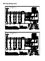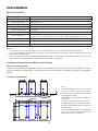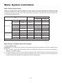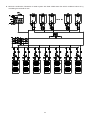
1
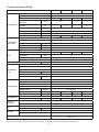
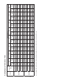
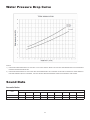
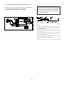
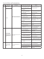
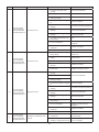
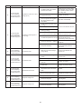
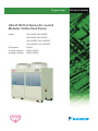
Engineer Data
UAL-D R410 A Series Air-cooled
Modular Chiller/Heat Pump
Model:
UAL210D5-UAL1680D5
UAL230D5-UAL1840D5
UAL210DR5-UAL1680DR5
UAL230DR5-UAL1840DR5
Refrigerant:
Cooling Capacity:
Heating Capacity:
R410A
60kW-544kW
64kW-528kW
ED-UAL-D-201401A
Literature No.: ED-UAL-D-201401A
Supersedes:
ED-UAL-D-201310A
Contents
Overview................................................................................................................................................................... 2
Nomenclature........................................................................................................................................................... 2
Features.................................................................................................................................................................... 2
Specifications........................................................................................................................................................... 4
Dimensions............................................................................................................................................................... 7
Performance Data..................................................................................................................................................... 8
Water Pressure Drop Curve................................................................................................................................... 11
Sound Data.............................................................................................................................................................. 11
Wiring Diagrams..................................................................................................................................................... 12
Installation............................................................................................................................................................... 13
Water System Installation...................................................................................................................................... 16
Commissioning and Operation............................................................................................................................. 23
Maintenance............................................................................................................................................................ 24
Control System Instruction................................................................................................................................... 27
Wired Controller Instruction.................................................................................................................................. 30
Error Code............................................................................................................................................................... 34
Note: Installation and maintenance are to be performed only by qualifiedpersonnel who are familiar with
local codes and regulations, and experienced with this type of equipment.
Caution: S
harp edges and coil surfaces are a potential injury hazard. Avoid contact with them.
Warning: Moving machinery and electrical power hazard may cause severe personal injury or death.
Disconnect and lock off power before servicing equipment.
1
Overview
DAIKIN air-cooled modular chiller/heat pump R22 series, DAIKIN UAL-D R410A series is a new generation of
air-cooled chillers/heat pumps. They ideally combine the advanced and mature chiller technology with new type
environment-friendly refrigerant. In addition, this series features outstanding performance, high capacity, low sound
level, easy installation, and flexible system management, taking the lead in the global market.
Nomenclature
UAL
210
D
R
M
5
-
F
CA
E
Export sales code
Detailed description
Power supply F: 380V/3Ph/50Hz
Refrigerant code 5: R410A
Code for modular connected units
M: master unit/single unit;
S: slave unit.
Function type R: heat pump;
Omitted for cooling only units.
Design series
Cooling capacity code, 21HP
DAIKIN air-cooled modular chiller
Features
Environment-friendly Refrigerant
DAIKIN is committed to protecting the global ecosystem and has developed air-cooled chiller/heat pump with
R410A, a new type of environment-friendly refrigerant. Without chlorine, the environment-friendly R410A causes no
harm to the ozonosphere (ODP=0).
Low Sound Level
Thanks to the newly designed spiral blades, the outdoor units feature smooth air flow, significantly reducing the
turbulence and lowering the air flow sound level. Unique compressor sound-insulation design and fully hermetic
volute compressor minimizes the operation noise. Moreover, unique Night Mode brings down nightly noise greatly
and ensures you a sound sleep.
Easy Installation
UAL R410 series is designed to best facilitate user installation. The refrigerant system is made hermetic in the
factory. Customers do not need to connect any copper pipe or refill refrigerant or invest more money for complex
water systems.
2
Multi-grade Modulation
UAL R410 series features 2-grade modulation which can be transformed to multi-grade modulations in modular
combinations. With operation grades controlled electronically, the unit exerts less shock to the power grid and
saves more energy.
Compact Size
Moreover, UAL R410 series features compact size. Its dimensions and weight are significantly reduced. UAL R410
can be lifted without large lifting tools and located on the roof, balcony or any possible outdoor space.
Reliable Operation
UAL R410 series adapts modular design and one by one start, reducing the impact upon the grid when starting. All
units have undergone strict and long-term test, ensuring reliable operation even under extreme hot/cold conditions.
Units themselves, moreover, have multiple protections. The security of units is maximally guaranteed.
Outstanding Performance
UAL R410 series features leading-edge scroll technology and name-brand accessories which are strictly tested for
high compatibility and reliability. Equipped with efficient scroll compressors and precise electronic expansion valves,
these units feature high EER and COP, especially at partial load.
Intelligent Control System
UAL-D features user-friendly intelligent control system. Micro chip and large-scaled LCD display are employed to
make the control swift and easy.
■Group control: One single controller can control a group made up by one master unit and maximum 15 slave units.
■BMS: UAL-D provides interfaces for BMS. One serial port can support maximum 31 gateway and one gateway
can support one master unit and maximum 15 slave units.
Basic Operating Mode
Fault Alarm And Protection
■ Cooling
■ Heating
■ 13 protections and fault alam functions
■ Indoor controller lock
Parameter Setting
Defrost Mode
■
■
■
■
■
■
■ Auto defrost
■ Mannual defrost
Real time setting
Weekly timing on/off (one on/off per day)
Cooling water inlet temperature
Heating water inlet temperature
Anti-freezing/defrost temperature setting
Defrost point A/B temperature setting
Memory Function
■ Backup battery for realtime clock
■Customized parameters preservation after
power failure
Parameter Display
Other Functions
■
■
■
■
■
■
■
■
■
■
Running status display
Setted inlet temperature
Actual inlet temperature
Timing point
Anti-freezing/defrost temperature
Error log inquiry
Average compressor worn time
Remote on/off
Water system two-way valve control
Auxiliary electric heating
NOTE:
■ THE LENGTH OF COMMUNICATION WIRE BETWEEN THE MASTER UNIT AND THE WIRED CONTROLLER IS 40M. THE LENGTH OF
COMMUNICATION WIRE ATTACHED TO THE SLAVE UNIT IS 5M.
■ THE MAIN BOARD OF THE UNIT PROVIDES AN INTERFACE FOR REMOTE CONTROL. BUT REMOTE CONTROLLERS ARE NOT
PROVIDED AND SHOULD BE INSTALLED ON SITE.
3
Specifications
General Data - R410A
MODEL
UAL210D5
UAL210DR5
UAL230D5
UAL230DR5
Ton
17
17
18.5
19.1
kW
60
60
65
68
Ton
--
17.9
--
18.5
kW
--
64
--
66
RATED TOTAL COOLING INPUT POWER
kW
18.8
19.8
19.2
21
RATED TOTAL HEATING INPUT POWER
kW
--
20.5
--
20
Btu/h/W
10.9
--
11.5
--
--
3.1
--
3.3
NOMINAL COOLING CAPACITY
NOMINAL HEATING CAPACITY
EER
COP
RATED COOLING RUNNING CURRENT
A
36
37.2
36.9
36.8
RATED HEATING RUNNING CURRENT
A
--
38.2
--
36.2
POWER SOURCE
REFRIGERANT
WATER FLOW
V/Ph/Hz
380-415V/3N~/50Hz
TYPE
R410A
CHARGE
kg/lb
17/37
17/37
17.2/37.9
17.2/37.9
COOLING
3
m /h
10.3
10.3
11.2
11.7
HEATING
3
m /h
--
11
--
11.4
kPa
38
38
44
37.3
WPD
UNIT DIMENSION
L×W×H
mm/in
1990 × 840 × 1840/78 × 33 × 72
PACKING DIMENSION
L×W×H
mm/in
2010 × 890 × 2010/79 × 35 × 79
NET WEIGHT
kg/lb
520/1145
540/1189
520/1145
515/1134
GROSS WEIGHT
kg/lb
570/1256
590/1300
570/1256
565/1244
OPERATING WEIGHT
kg/lb
530/1167
555/1222
530/1167
525/1156
NOTES:
1. T HE SPECIFICATIONS GIVEN IN THE TABLE WILL BE SUBJECT TO THE MODIFICATIONS ON PRODUCT DESIGN BY THE
MANUFACTURER.
2. NOMINAL COOLING CAPACITY CONDITION: LWT 7°C, WATER FLOW 0.172 [M3/(H•KW)], OUTDOOR TEMPERATURE 35°C.
3. NOMINAL HEATING CAPACITY CONDITION: LWT 45°C, WATER FLOW 0.172 [M3/(H•KW)], OUTDOOR DRY-BULB TEMPERATURE 7°C,
WET-BULB TEMPERATURE 6°C.
4
Components Data - R410A
MODEL
UAL210D5
TYPE
UAL210DR5
STAINLESS STEEL
MODEL NAME
ACH230-58DQ
NOMINAL WATER FLOW
COOLING
L/s
NOMINAL WATER FLOW
HEATING
L/s
WATER VOLUME
BPHE PRESSURE DROP
ACH230-58DQ
--
L
37.3/5.4
UNIT WATER PRESSURE DROP
kPa/psi
38/5.5
38/5.5
COPPER
TYPE
INNER GROOVE
WALL THICKNESS
mm
OUTER DIAMETER
mm
7.94
TUBE HEIGHT
TH
36/40
0.71
ALUMINUM
THICKNESS
WHITE
HYDRAULIC
mm
14
2
2
m /ft
3.43/36.9
BROAD WHEEL AXIAL FANS WITH LOW NOISE
2
GALVANIZED STEEL
V/Ph/Hz
380V/3N~/50Hz
MOTOR POLES
AIR VOLUME
6
CMH/CFM
12000/7059
TYPE
HERMETIC SCROLL COMPRESSOR
MODEL NAME
SH140A4ALC
QUANTITY
2
NUMBERS OF CIRCUITS
POWER SUPPLY
HYDRAULIC
3
BLADE MATERIAL
POWER SUPPLY
WHITE
0.12
QUANTITY
CASING
44/6.4
26
DN50/DN2
TYPE/DRIVE
OIL
11.4
kPa
TOTAL FACE AREA
FLOW
CONTROL
--
mm/in
FIN PER INCH
REFRIGERANT
11.17
PIPING CONNECTION
ROWS
COMPRESSOR
11.2
6.56
TYPE
CONDENSER
FAN
DP300X78
11
MATERIAL
FIN
ACH230-58DQ
10.3
MATERIAL
CONDENSER
COIL TUBE
UAL230DR5
BRAZED PLATE HEAT EXCHANGER
PLATE MATERIAL
EVAPORATOR
UAL230D5
2
V/Ph/Hz
380V/3N~/50Hz
RATED RUNNING CURRENT
A
19.22
19.22
20.8
20.8
RATED INPUT POWER
W
10862
10862
10800
10800
17.2
17.2
TYPE
CHARGE
R410A
kg
17
TYPE
17
EXV
MODEL
UKV-25D5
MODEL
POE
CHARGE
L
3.25
COLOUR
RAL 7032 PEBBLE GREY
MATERIAL
EG
H/L PRESSURE SWITCH/THERMAL AND CURRENT OVERLOAD
PROTECTOR
PROTECTION DEVICES
NOTE: ALL SPECIFICATIONS ARE SUBJECTED TO CHANGE BY THE MANUFACTURER WITHOUT PRIOR NOTICE.
5
Electrical Data - R410A
MODEL
UAL210D5
UAL210DR5
INSULATION GRADE
IPX4
POWER SOURCE
V/Ph/Hz
380/3/50
RATED RUNNING CURRENT
A
2.5/1.7
MOTOR OUTPUT
W
900
POLES
FAN SPEED
6/10
H/L
RPM
780/477
INSULATION GRADE
F
IP
COMPRESSOR
UAL230DR5
F
IP
FAN MOTOR
UAL230D5
IPX4
POWER SOURCE
V/Ph/Hz
380/3/50
RATED RUNNING CURRENT
A
19.22
20.8
LOCKED ROTOR AMP
A
115
124
UNIT OPERATING CURRENT
A
35.5
36.0/37.2
36.9
36.8/36.7
UNIT MAX RUNNING CURRENT
A
44.5
45
47
47.7
NOTES:
1) ALL SPECIFICATIONS ARE SUBJECTED TO CHANGE BY THE MANUFACTURER WITHOUT PRIOR NOTICE.
2) M AX RUNNING CURRENT IS TESTED UNDER BELOW CONDITION: COOLING OUTDOOR DRY-BULB TEMPERATURE 43°C;
HEATING DRY-BULB TEMPERATURE 21°C, WET-BULB TEMPERATURE 15.5°C.
3) THE RATED RUNING CURRENT AND POLES ARE TESTED IN THE HIGH SPEED AND LOW SPEED.
Safety Devices
MODEL
TYPE
HIGH PRESSURE
SWITCH
SAFETY
DEVICE
UAL210DR5
UAL230D5
UAL230DR5
PSW,H20PS
PSW,H20PS
PSW,H20PS
PSW,H20PS
OPEN
MPa
4.15 ± 0.1
4.15 ± 0.1
4.15 ± 0.1
4.15 ± 0.1
CLOSE
MPa
3.11 ± 0.1
3.11 ± 0.1
3.11 ± 0.1
3.11 ± 0.1
TYPE
LOW PRESSURE
SWITCH
UAL210D5
N/A
OPEN
MPa
N/A
CLOSE
MPa
N/A
PHASE SEQUENCER
DISCHARGE THERMOSTAT
SETTING
YES
°C/°F
130/266
NOTE: ALL SPECIFICATIONS ARE SUBJECTED TO CHANGE BY THE MANUFACTURER WITHOUT PRIOR NOTICE.
6
B
Air-conditioner
water outlet Rc2"
A
Dimensions
335
Mounting
hole of anchor
bolt 14-14x20
地脚螺栓固定孔
14-14x20
950
950
101101
170
170
45
14
877
845
20
16
45
16
14x20 Enlarged drawing for
14x20地脚螺栓固定孔放大图
Mounting hole of anchor bolt
1990
1840
1575
265
840
空调进水 Rc2
Air-conditioner
B
water entry Rc2"
Air-conditioner
空调出水Rc2
A
water outlet Rc2"
335
Modular Air Cooled Chiller/Heat Pump
UAL210DM5/DS5 UAL210DRM5/DRS5
UAL230DM5/DS5 UAL230DRM5/DRS5
Unit: mm
Model
A
B
171
369
165
390
UAL210DM5/DS5
UAL210DRM5/DRS5
UAL230DM5/DS5
UAL230DRM5/DRS5
7
Performance Data
Operating Range
Heating mode
Cooling mode
Ambient temp (°C)
(℃)
Ambient temp
(°C)
(℃)
Temperature range
Leaving water temp (°C)
(℃)
Temperature range
Leaving water temp (°C)
(℃)
8
9
UAL230DR5
UAL230D5
UAL210DR5
UAL210D5
Model
70.6
75
79.8
86.7
93
103.5
67
71.3
75.8
83.2
91.1
104.2
72.5
77.2
82
90.1
98.6
112.8
74.5
79
83.7
90.7
96.9
105.1
5
7
9
12
15
20
5
7
9
12
15
20
5
7
9
12
15
20
5
7
9
12
15
20
17.8
17.2
16.6
15.9
15.4
14.9
17.1
16.1
15.5
15
14.6
14.2
17.8
16.6
16
15.5
15
14.6
15.4
14.9
14.6
14.1
13.8
13.6
15°C
Outlet water
temp (°C)
Cooling
Power
capacity
(kW)
(kW)
102.5
93.7
87.1
80.1
75.4
70.6
111.2
96.7
88
79.9
75
70.3
102.8
89.4
81.3
73.8
69.3
65
101.7
89.7
82.5
75.7
71
66.5
18.7
18.1
17.5
16.8
16.4
15.9
18.3
17.1
16.4
16
15.6
15.2
18.7
17.6
16.9
16.5
16.1
15.7
16.8
16.1
15.7
15.2
14.9
14.7
Power
(kW)
20°C
Cooling
capacity
(kW)
Cooling Capacity Performance Table
99.8
90.5
83.6
76.5
71.8
66.7
108
93.8
85.3
77.1
72.8
68.1
99.8
86.6
78.8
71.2
67.3
62.9
99.7
86.5
78.6
71.6
66.9
62.9
Cooling
capacity
(kW)
19.7
19
18.4
17.8
17.3
16.9
18.8
18
17.5
17
16.6
16.2
19.4
18.6
18.1
17.5
17.1
16.7
18.1
17.4
17
16.5
16.3
16
Power
(kW)
25°C
97.2
87.4
80.6
73.9
69.4
64
103
89.7
81.7
73.5
69.4
64.7
95.2
82.9
75.5
67.9
64.1
59.8
95.3
82.6
75
68.4
63.4
59.4
Cooling
capacity
(kW)
21.2
20.5
19.8
19.1
18.7
18.3
20.1
19.1
18.5
18.1
17.8
17.4
20.8
19.7
19
18.7
18.4
18
19.4
18.7
18.3
17.8
17.5
17.2
Power
(kW)
30°C
94.6
84.2
77.7
71.3
68
61.3
98.5
84.7
76.4
69.5
65
60.9
91.1
78.3
70.6
64.2
60
56.3
90.5
78.7
71.6
64.9
60
55.3
Cooling
capacity
(kW)
22.8
21.9
21.2
20.5
20.1
19.6
21.3
20.5
20
19.6
19.2
18.8
21.9
21.1
20.7
20.2
19.8
19.4
20.8
20
19.5
19
18.8
18.5
Power
(kW)
35°C
Ambient temp. (°C)
88
78.3
71.7
65.4
61.1
56.3
91.6
79.1
71.6
64.7
60.4
56
84.5
73
66.1
59.8
55.8
51.7
84.5
73.7
67.2
60.8
55.6
50.9
Cooling
capacity
(kW)
24.5
23.8
23
22.4
21.9
21.6
23
22.2
21.7
21.3
21
20.5
23.7
22.9
22.4
22
21.6
21.1
22.9
21.9
21.3
20.7
20.4
20.1
Power
(kW)
40°C
81.4
72.4
65.8
59.5
55.3
51.3
85.8
73.3
65.8
59.3
55.1
51.3
79.2
67.7
60.8
54.7
50.9
47.4
78.3
68
61.8
55.8
50.9
46.3
Cooling
capacity
(kW)
26.2
25.6
24.9
24.3
23.8
23.5
24.7
23.9
23.4
23
22.6
22.2
25.6
24.7
24.1
23.7
23.3
22.9
24.9
23.7
23
22.4
22.1
21.8
Power
(kW)
45°C
77.4
68.8
62.2
55.9
51.7
48.3
78.8
67.6
60.9
54.4
50.2
46.3
72.6
62.4
56.3
50.3
46.4
42.8
74.8
63.5
56.7
51
46.9
42.4
Cooling
capacity
(kW)
27.2
26.7
26
25.4
25
24.7
25.9
25.2
24.8
24.3
24.1
23.6
26.8
26
25.5
25.1
24.9
24.3
25.7
24.7
24.1
23.7
23.4
23.1
Power
(kW)
48°C
10
42.6
41.5
40.3
39.1
38.4
37.3
42.1
41.1
39.9
38.5
37.7
36.4
30
35
40
45
50
55
30
35
40
45
50
55
23.4
21.3
19.4
17.5
16
14.6
23.5
21.4
19.7
18.1
16.6
15
Outlet water
-10°C
Temp
Heating
(°C)
Power
capacity
(kW)
(kW)
40.7
42.3
43.4
44.9
46.3
47.6
42.8
44.2
46
47.4
49
50.7
Heating
capacity
(kW)
23.7
21.5
19.6
17.6
16.2
14.7
24
21.8
19.9
18.2
16.7
15.2
Power
(kW)
-5°C
47.9
49.4
51.1
52.4
53.9
55.1
48.3
51.4
53.9
55.8
58.3
60.8
Heating
capacity
(kW)
0°C
23.9
21.7
19.8
17.9
16.3
15
24.3
22
20.3
18.4
16.9
15.4
Power
(kW)
61.7
63.9
66
67.4
68.6
70
57.4
60.5
64
65.9
67.8
69.8
Heating
capacity
(kW)
7°C
24
21.9
20
18.1
16.6
15.1
24.5
22.2
20.5
18.7
17.1
15.5
Power
(kW)
63
65
67.1
68.4
69.7
71
61
64.1
67.2
69.6
71.5
73.4
Heating
capacity
(kW)
24.2
22
20.1
18.3
16.7
15.2
24.6
22.4
20.7
18.9
17.3
15.7
Power
(kW)
10°C
Ambient temp. (°C)
NOTE: PARAMETERS IN THE ABOVE TABLE ARE MEASURED WHEN THE UNIT OPERATES AT THE RATED WATER FLOW.
UAL230DR5
UAL210DR5
Model
Heating Capacity Performance Table
65.2
67
68.8
70.2
71.5
72.6
65.6
68.9
71.3
73.5
75.8
78.2
Heating
capacity
(kW)
24.4
22.2
20.3
18.4
16.7
15.3
24.7
22.6
20.9
19
17.5
16
Power
(kW)
15°C
73.8
75.5
77.3
78.7
79.9
80.8
70.5
73.2
76.3
78.6
80.7
82.9
Heating
capacity
(kW)
24.7
22.5
20.5
18.6
17
15.4
24.8
22.8
21.1
19.1
17.7
16.3
Power
(kW)
21°C
82.6
84.3
85.7
86.8
87.9
88.3
77.9
80.7
83.8
86.3
88.1
90
Heating
capacity
(kW)
24.9
22.6
20.7
18.8
17.2
15.6
25
23
21.3
19.2
18
16.7
Power
(kW)
30°C
Water Pressure Drop Curve
NOTES:
1) THE WATER PRESSURE DROP OF THE UNIT IS THE TEST RESULT WHEN A PLATE HEAT EXCHANGER AND THE ACCESSORY
Y-SHAPED FILTER ARE INSTALLED.
2) THE WATER RESISTANCE OF THE PLATE HEAT EXCHANGER AND THE Y-SHAPED FILTER ARE TESTED WITH PURE WATER.IF
THE ONSITE WATER QUALITY CHANGES, THE TEST RESULT MAY BE DIFFERENT FROM THAT SHOWN IN THE FIGURE.
Sound Data
Acoustic Noise
Units
Octave Sound Pressure Level (dB,ref20μPa)
63Hz
125Hz
250Hz
500Hz
1kHz
2kHz
4kHz
8kHz
dB(A)
UAL210D/DR
43.9
50.1
54.0
57.7
56.2
54.2
50.5
40.7
63.7
UAL230D/DR
45.3
52.6
55.5
59.6
59.8
57.7
50.2
41.2
65.8
11
Wiring Diagrams
MODEL: UAL210/230DM5/DS5
MODEL: UAL210/230DRM5/DRS5
12
Installation
Working Condition
Item
Description
Power supply voltage
Rated voltage ± 10%
Power supply frequency
Rated frequency ± 1%
Variations between phases
Rated voltage ± 2%
Air quality
Must not contain solute that can corrode copper, aluminum or iron.
Flow rate of chilled water
0.5 - 2.0m/s
Pressure of chilled water
< 0.7MPa
"Must not contain solute that can corrode copper, iron, or welding material.
For details on the water quality requirements, see Chapter 9: Water Quality Management (page 42)."
Quality of chilled water
Installation site
Take anti-snow and ventilation measures as required.
Ambient temp.
Refer to the figure above.
Relative humidity
< 90%
NOTES:
1. THE UNIT IS STRICTLY TESTED BEFORE DELIVERY AND CAN WORK SAFELY IN THE RATED WORKING CONDITIONS.
2. FOR THE PERFORMANCE PARAMETERS OF THE UNIT IN DIFFERENT WORKING CONDITIONS, SEE 3.3 REFERENCE TABLE FOR
PERFORMANCE PARAMETERS.
3. THIS IS THE NORMAL OPERATING TEMPERATURE RANGE FOR THE UNIT. BEYOND THIS TEMPERATURE RANGE, THE UNIT CAN
ONLY OPERATE FOR A SHORT MOMENT BEFORE A FAILURE ALARM IS TRIGGERED.
Installation Dimensions and Environment Limits
Machine Installation Space
Units must be installed by DAIKIN service staff or by specially trained personnel. Units must installed by following
relevant national and local electric, building and environment protection standards as well as the installation
manual.
Assembling Unit Modules
NOTE:
50
THE GROUNDWORK MUST BE A CONCRETE
FLOOR OR A V-IRON STRUCTURE THAT IS
300
STRONG ENOUGH TO BEAR THE OPERATION
PRESSURE OF THE UNIT.
地脚螺 栓M12x200
N REPRESENTS THE NUMBER OF MODULES
INSTALLED.
>1245x(N-1)+ 1575
>1245x(N-1)
845
>400
845
845
365
EACH UNIT MUST BE FIXED BY 4 M12 BOLTS;
6 RUBBER CUSHIONS OF 20MM THICK MUST
400
365
BE INSTALLED BETWEEN THE UNIT AND THE
1560
THE GROUNDWORK MUST HAVE DRAINING
FACILITIES TO DISCHARGE CONDENSATE
WATER AND DEFROSTING WATER.
400
>2460
GROUNDWORK.
13
Space Allocated for A Single Chilled Water Unit
Deflector
导流装置
>45°
≥L1+h2
>300
h2
h1
>1000
≥L1+h1
≥L1
前面
Front
Back
后面
≥L3
≥ L1
≤400
<210>
≥L2
≥ L1
<610>
≥L1
前面
Front
≤700
Front
前面
前面
≥L3
≥L2
前面
≥L2
Unit: mm
L1
L2
L3
400
800
100
后面
14
≥L1
后面
≥L1
后面
≥L1
后面
≥L1
Space Allotted for An Array of Chilled Water Units
Installing Chiller
■The user manual, warranty card, accessories, and packing list are place at the right side of the unit, as illustrated
by the shaded part of the figure on the left.
■Reserve sufficient maintenance space if possible.
■If the unit is installed in a place where it snows in winter, proper measures must be taken to protect the unit
against snow and ensure that the unit works properly.
■The groundwork should be made of concrete or supporting structures. While designing the groundwork, you
must fully consider the strength of the floor, water discharge (the unit discharges water
while working), pipelining and wiring. If the floor is not strong enough, the unit might fall
off and breakdown, even incur bodily injuries.
■Screw down the chilled water unit using anchor bolts so that it will not fall off in case of
strong wind or earthquakes. To avoid damages caused by strong wind or earthquakes,
The unit must be securely installed at a proper place to avoid direct hit of strong winds.
■Depending on mounting conditions, operation vibration might pass through the
groundwork and generate noises in the floor and walls. Therefore, proper vibration
dampening mechanisms (such as bumper cushion, bumper frame etc.) should be in
place.
■Corners and edges should be properly installed. Otherwise, the unit might get unbalanced and cause the
grounding pins to bend. The unit might fall off and cause bodily injuries if it is not properly installed.
Hoisting Chillers
Please hoist the unit according to the following illustrations. Tie the cables to the four corners of the unit while
moving it. If you tie the cables to only three corners of the unit, the unit might get unbalanced and fall off.
NOTES:
■ CHILLED WATER UNITS MUST BE MOVED WITH GREAT CARE.
■ ACCESSORY STRIPS CANNOT BE USED TO HOIST OR MOVE THE UNIT AS THEY MIGHT BREAK AND CAUSE UNEXPECTED
ACCIDENTS.
■ DO NOT TOUCH THE HEAT SINKS OF THE HEAT EXCHANGER BARE-HANDEDLY AS THEY MIGHT CUT YOUR FINGERS.
■ DISPOSE ALL PLASTIC BAGS PROPERLY AND KEEP THEM AWAY FROM CHILDREN.
15
Water System Installation
Water Quality Requirements
Water in the water system must be softened to prevent scale in the heat exchanger and affecting the heat
exchanger performance. Water not softened can also cause scale in the water pipes and cause the water
resistance to increase. This affects the water flow and the performance of the water pump. Softened water must
meet the following requirements.
Benchmark items
Item
Benchmark value
pH (25°C)
Corrosion
Scaling
7.0 - 9.0
○
○
○
Conductivity
(25°C)
μS/cm
< 800
○
Cl-
mg (Cl-)/L
< 200
○
mg (SO4 )/L
< 200
○
mg (CaCO3)/L
< 100
Total hardness
mg (CaCO3)/L
< 200
Fe
mg (Fe)/L
< 1.0
○
0
○
○
SO4
2-
Acid consumption
(pH = 4.8)
2-
Reference items
Tendencies
S
2-
2-
mg (S )/L
+
mg (NH )/L
< 1.0
SiO2
mg (SiO2)/L
< 50
NH
+
○
○
○
○
NOTE: ○ REPRESENTS FACTORS THAT MAY CAUSE CORROSION OR SCALING.
Water System Installation Schematic Diagram
Connecting Water Pipes
No water pump is provided as an accessory. A proper water pump must be installed to overcome resistance of the
water pipes.
■Water pressure gauges and thermometers must be installed at the water inlets and outlets to facilitate the
reading of unit operation status.
■The heat exchanger at the water side is made of stainless steel. Water scale may accumulate depending on
the water quality and must be cleared using chemicals from time to time. Therefore, a chemical cleaning pipe
connector needs to be installed at the water pipes (see the following figure).
16
The water flow must be in the rated range. If the water flow is too small, scale may accumulate and degrade the
performance of the unit, cause the antifreeze device to activate, or cause rust points and refrigerant leakage. If the
water flow is too large, the unit may be corroded due to water impact.
■A adiabatic water tank with a proper volume is suggested to installed. If the capacity is too small, the unit might
frequently restart, which causes wear and tear on the compressor.
■An expansion water tank must be installed at the return water side of the water system to adapt to water
pressure variations in the water supply system caused by ambient temperature changes.
■An auto relief valve must be installed at the highest point in the water system. A suitable water discharge valve
must be installed at the lowest point in the water system.
■The water pipes must be adiabatic to avoid heat loss and condensate water.
■Please follow the "Illustration for water system installation" and drawings from the design institute while installing
the water system.
■Install the Y-shaped water filter inside the water inlet pipe and rinse the filter screen after commissioning.
■Before injecting water, make sure that no sand, rubble, rust, soldering tin residue or other impurities exist in the
pipe, as these things might damage the heat exchanger.
While rinsing the water system, please bypass the unit and the terminal heat exchanger using by-pass valves.
■Installation illustration for the water system of a single unit:
膨胀水箱
补
水
冷水机组
药
品
清
洗
口
软
接
头
过
滤
器
闸
阀
压
力
闸 计
阀
温
度
计
自
动
排
气
阀
水
泵
排
水
冷(热)水进口
1
3
加热器
排
水
2
17
补
水
储水箱
排
水
冷(热)水出口
■Multi-unit combination, illustration for water system with fixed chilled water flow which conditions indoor air by
modulating the terminal air rate
排气
风机盘管
风机盘管
风机盘管
风机盘管
满水
风机盘管
补水
DN20
排水
3
1
3
2
1
3
2
1
3
2
1
3
2
18
1
闸阀
闸阀
闸阀
闸阀
闸阀
DN20
3
2
1
3
2
1
2
■Illustration for variable flow rate water system which adjusts indoor temperature by adjusting flow rate of chilled
water (modular combination of multiple units)
排气
风机盘管
风机盘管
风机盘管
风机盘管
满水
风机盘管
补水
DN20
排水
3
1
3
2
1
3
2
1
3
2
1
3
2
Legends for the water system illustration:
19
1
闸阀
闸阀
闸阀
闸阀
闸阀
DN20
3
2
1
3
2
1
2
Size of the main connecting pipe for modular combinations:
Unit Qty.
1
2-3
4-5
6-10
Size of main connecting pipe (inch)
≥2
≥3
≥4
≥5
NOTE: WHEN CLEANING THE WATER SYSTEM, PLEASE SHUT
① ② GATE VALVE AND OPEN
③ GATE VALVE MARKED IN THE
DIAGRAM OF ALL THE UNITS, IN ORDER TO BYPASS THE UNITS, SO THE IMPURITIES CAN BE PREVENTED FROM ENTERING THE
PLATE HEAT EXCHANGER AND THE EFFICIENCY AND SERVICE LIFE OF PLATE HEAT EXCHANGER CAN NOT BE AFFECTED.
Hydraulic Calculation and Pipe System
Pipe Design for the Air-Conditioning System
■The pipes of an air conditioning system must have sufficient transportation capacities. For example, the water
system must ensure that the water flowing through the air conditioning unit or fan coil reaches the rated flow rate
to ensure that the unit works properly.
■Deploy pipes properly. Use pipes with reverse return if possible. Although the initial investment is increased
a little, the water flow in the system is more stable. If pipes have no reverse return design, pressure between
branch pipes must be balanced in the design process.
■When determining the diameters of pipes, ensure that the transportation capacity is sufficient, the resistance
and noise is minimal, and that the unit works economically. A larger pipe diameter requires more investment,
but the flow resistance is smaller, the circulation pump consumes less energy, and the operation cost is smaller.
Therefore, a balance needs to be achieved between the operation cost and investment by designing the pipe
diameter properly. Avoid a large water flow with small temperature variation to ensure that the pipe system is
economical.
■In the design process, calculate water resistance accurately to ensure that water pressures between circuits are
well balanced and that the air conditioning system works with the best water and thermal conditions.
■The pipe system of an air conditioning system must meet the adjustment requirements for partial workload.
■The pipe system of an air conditioning system should use energy saving technologies whenever possible.
■Pipes and accessories of the pipe system must meet the related requirements.
■The design of the pipe system must facilitate maintenance, operation, and adjustment.
* Determining the diameter of pipes in the air conditioning system
The pipe diameter is determined based on the following:
In the formula: mw-------water flow m3/s
v---------water speed m/s
The water speed should be determined by the recommendations in the first table and design the water pipe
diameters accordingly, or you can determine the water pipe diameter based on water flow in the second table.
20
Table 1: Recommended water speed (m/s)
Diameter (mm)
12
20
25
32
40
50
65
80
Closed water system
0.4 - 0.5
0.5 - 0.6
0.6 - 0.7
0.7 - 0.9
0.8 - 1.0
0.9 - 1.2
1.1 - 1.4
1.2 - 1.6
Open water system
0.3 - 0.4
0.4 - 0.5
0.5 - 0.6
0.6 - 0.8
0.7 - 0.9
0.9 - 1.0
0.9 - 1.2
1.1 - 1.4
Diameter (mm)
100
125
150
200
250
300
350
400
Closed water system
1.3 - 1.8
1.5 - 2.0
1.6 - 2.2
1.8 - 2.5
1.8 - 2.6
1.9 - 2.9
1.6 - 2.5
1.8 - 2.6
Open water system
1.2 - 1.6
1.4 - 1.8
1.5 - 2.0
1.6 - 2.3
1.7 - 2.4
1.7 - 2.4
1.6 - 2.1
1.8 - 2.3
Table 2: Pipe diameter and resistance loss in unit length
Closed water system
Open water system
Diameter of the
steel tube (mm)
Water flow (m /h)
kPa/100m
Water flow (m3/h)
kPa/100m
15
0 - 0.5
0 - 60
--
--
20
0.5 - 1.0
10 - 60
--
--
25
1-2
10 - 60
0 - 1.3
0 - 43
32
2-4
10 - 60
1.3 - 2.0
11 - 40
40
4-6
10 - 60
2-4
10 - 40
50
6 - 11
10 - 60
4-8
--
65
11 - 18
10 - 60
8 - 14
--
80
18 - 32
10 - 60
14 - 22
--
100
32 - 65
10 - 60
22 - 45
--
125
65 - 115
10 - 60
45 - 82
10 - 40
3
NOTE: PARAMETERS IN THE PRECEDING TABLE MAY VARY BASED ON THE DESIGN MANUAL. FOR DETAILS, SEE THE "HVAC
DESIGN MANUAL".
Water Storage Tank Volume Calculating
Model
Setting temperature of return water (°C)
Minimum working volume Vmin. (l)
14
198
13
234
12
286
11
367
10
514
9
857
14
224
13
265
12
324
11
416
10
583
9
971
UAL210DM5/DS5 UAL210DRM5/DRS5
UAL230DM5/DS5 UAL230DRM5/DRS5
NOTES:
■ T HE MINIMUM WORKING VOLUME REFERS TO THE ADDED-UP VOLUME OF THE MAIN WATER PIPE, WATER TANK AND
CONSTANTLY-OPEN TERMINALS OF 2-WAY VALVES IN THE WATER CIRCULATION SYSTEM.
■ THE ACTUAL WORKING VOLUME OF THE WATER SYSTEM MUST BE LARGER THAN VMIN; OTHERWISE THE UNIT WILL SEND
OUT ALARMS AND SHUT DOWN FREQUENTLY.
■ IF THE ACTUAL RESULTFUL VOLUME OF THE WATER SYSTEM V IS LESS THAN VMIN, PLEASE INSTALL A TANK THE VOLUME OF
WHICH IS L (L=VMIN-V).
21
Example for water system volume calculation:
There are 2 UAL230DR5 modular units with temperature of return water set to 12°C, a main inlet/out water pipe of
DN80 and 50m long and 10 fans with coils constantly open (each has a volume of 1.5 L)
Calculation: Volume of main inlet/outlet water pipe = 3.14 * [(80/2)/100] 2 * 500 = 251 L
Volume of terminal fan coils = 10 * 1.5 = 15
According to the table above, Vmin. = 324 L
To avoid frequent unit startup/shutdown and alarms, the volume of the water tank should be no less than Vmin.
- V = 324 - 251 - 15 = 58 L
Calculating Volume of Expansion Water Tank
An expansion water tank with a proper volume must be installed to adapt to water volume changes as the
temperature changes and avoid freezing burst and pressure instability at the water pump inlet.
The expansion water tank can also be used to supplement water and discharge air.
Calculating volume of expansion water tank.
Vp=α*Δt*Vs
Vp----effective volume of the expansion water tank (volume of water between the signal pipe and the overflow pipe). m3
α----volume expansion coefficient of water (α =0.0006/°C)
Δt----max. water temperature variation °C
Vs----water volume in the system (total water volume in the system and pipes) m3
Model Selection Principles for the Water Circulation Pump
■ Water flow in the water circulation pump ≥ rated water flow × 1.1
Closed water circulation system: Water circulation pump lift ≥ (Pipe resistance of the water system + Partial
resistance of the water system + Water pressure drop of the unit) × 1.1
■Open water circulation system: Water circulation pump lift ≥ (Static resistance of the water system + Pipe
resistance of the water system + Partial resistance of the water system + Water pressure drop of the unit) × 1.1
■In the case that multiple units share the same pump, the pump lift is calculated according to the circuit that has
the maximum resistance (usually the unit that is farthest away from the pump).
NOTE: THE WATER FLOW OF THE UNIT SHOULD CALCULATE ACCORDING THE WATER FLOW RANGE.
■Water flow range
Model
Max. value (m3/h)
Flow range
3
Rated value (m /h)
3
Min. value (m /h)
UAL210DM5/DS5
UAL210DRM5/DRS5
UAL230DM5/DS5
UAL230DRM5/DRS5
13.4
13.4
14.6
15
10.3
10.3
11.2
11.52
7.2
7.2
7.8
8
22
Commissioning and Operation
Items to be Confirmed before Turning on Unit
Note: Before the pilot run, check that the
following conditions are met and read
the "Safety Precautions" again.
■Ensure that the water pump and the unit are connected.
Use the PCB controller to Control the on and off the water pump using the water pump output on the PCB
controller; otherwise the BPHE may burst due to freezing.
The water pump connection point must have no voltage. If a voltage circuit is connected, basic components may
be damaged.
■Power on the unit to preheat the crankcase for at least 12 hours before starting up the unit for the first time or
after a long-term stoppage. This ensures that the compressor works properly.
■Before turning on the unit, check that the water pump is filled with water.
Before turning on the water pump, open the water supply valve, fill the pump with water, and discharge free air
in the system
■Wiring of the unit: Check that the diameter of the wires meets requirements; the wires are correctly connected;
the grounding line is securely connected;
■Before turning on the unit, clean the water system and ensure that pipes are clean without contaminants. For
the cleaning method, see 4.5 Connecting Water Pipes
■Make sure that the working conditions do not exceed the rated working range.
Items to be Checked during the Pilot Run
Check the following items after the unit has worked properly for a period of time:
S/N
Item
Checking Method
Reference Standard
1
Power supply voltage
Voltage
Rated voltage ± 10%
2
Working current of a single compressor
Current
13 - 23A
3
Working current of a single fan
Current
2 - 5A
4
Inlet water temperature in cooling operation
Temperature
15- 20°C
5
Outlet water temperature in cooling operation
Temperature
6 -15°C
6
Inlet water temperature in heating operation
Temperature
30 - 45°C
7
Inlet/outlet water temperature difference
Temperature
2 - 7°C
8
Discharge air temperature of the compressor
Temperature
65 -115°C
9
Low pressure in cooling mode
Pressure
6.5 - 10.0bar
10
High pressure in cooling mode
Pressure
22 - 41.5bar
11
Low pressure in heating mode
Pressure
3.0 - 10.0bar
12
High pressure in heating mode
Pressure
22 - 33bar
13
Vibration and operation noise
Listen or touch
No abnormal vibration or noise
NOTE: THE REFERENCE STANDARDS ARE USED TO CHECK WHETHER A UNIT WORKS PROPERLY ONSITE. REFERENCE
STANDARDS ARE DETERMINED BASED ON THE MAXIMUM AND MINIMUM WORKING CONDITIONS. IF REFERENCE STANDARDS ARE
EXCEEDS AFTER THE UNIT HAS PROPERLY WORKED FOR A PERIOD OF TIME, CONTACT THE LOCAL DEALER OR DAIKIN FOR HELP.
23
Maintenance
Repair
Note: Before checking and maintaining the unit, confirm the
safety precautions again.
Note: Before delivery, strict factory test is conducted to ensure
the unit works at optimal performance. The unit must be
maintained from time to time.
■The unit can only be repaired and serviced by specially-trained technicians. After a unit is serviced, safety
controls must be checked and analyzed before the unit is turned on.
Items to be Checked Periodically
■Clean the fin heat exchanger periodically.
To optimize heat exchange efficiency of the condenser, check that the external part of the condenser is clean
without leaves, cotton fibers, insects or other impurities which might clog up fins of the condenser. Use water or
water vapor while cleaning to clean it.
■Check the status of the chilled water from time to time.
Discharge water by loosening the air or water discharge plug.
If the water quality degrades, replace water in the system timely. (for the reference standards, see page 42)
Contaminated water can degrade the cooling capacity and corrode the heat exchanger and water pipes.
■Check whether free air exists in the water pipe system.
Free air may get into the system even during the air discharging process. Discharge air from time to time.
■Clean the Y-shaped water filter in the water system periodically.
■Replenishing refrigerant and lubricant.
Each unit is filled with enough refrigerant and lubricant before delivery.
If the system operates smoothly, customers neither need nor are allowed to replenish or change the refrigerant
or lubricant.
If replenishment is necessary due to leakage, please refill the quantity specified in the nameplate of the unit.
24
Maintenance
The unit must be checked on a routine basis to ensure performance. Routine check is the best way to reduce
downtime and waste. The following needs to be checked on a routine basis:
Items
Monthly
Quarterly
Once half a
year
Once a year
If necessary
1. Compressor
Performance appraisal; whether there is
abnormal sound
●
Whether wires are securely connected
●
Whether the working current is abnormal
(fluctuation: 10%)
▲
Discharge air temperature of the compressor
▲
Check the oil level
▲
Check the color of the lubricant
▲
2. Controller
Check parameter settings
▲
Check protective device
▲
Delay protector
▲
Phase order protector
▲
High/low pressure switch
▲
Differential water pressure switch/water flow
switch
▲
Overload protector
▲
Protector against extreme temperature of
discharged air
▲
3. Plate heat exchanger
Check the water quality
●
Clean the plate heat exchanger
▲
Seasonal protection measures
▲
(anti-freeze in winter)
4. Fin heat exchanger
Clean the fin heat exchanger
▲
5. Others
Whether the Y-shaped filter needs to be cleaned
or replaced
●
Whether bolts have loosened
●
NOTE: THE PRECEDING MAINTENANCE PLAN IS FOR REFERENCE ONLY. THE MAINTENANCE PLAN MAY VARY BASED ON REGION.
● INDICATES ITEMS TO BE CHECKED BY CUSTOMERS; ▲ INDICATES ITEMS TO BE CHECKED BY SERVICE PERSONNEL.
25
Water Processing Method
To ensure effective operation and durability, cleaning, washing and chemical processing are very important for
water systems. Different types of water circuits need to be cleaned in different ways.
■Close Re-Circulation System
Water systems of this type generally require no adjustment to subdue scale, and require no chemical to
suppress mud and alga. This type of water system is recommended. Closed recycle systems may need anticorrosion measures, including the following (for reference only):
NaNO2, borate and inhibitors for organic materials
a. NaNO2, borate and silicate
b. High density chromate solution and pH control
c. pH and sulfite control
d. Polyphosphate salt and silicate
e. Alkali, phosphate and sulfite control
Because it is hard to control water quality, for closed recycle systems, we recommend that the total density of
copper pipe inhibitors such as NaNO2, borax, silicate and benzothiazole should be no less than 1400 ppm. The
inhibitor NaNO2 is soluble in glycol, and can be used in northern areas or in the subsystem of solar power systems.
■Open Re-circulation System
This type of water system is generally not recommended. They are exposed to the atmosphere, and are
susceptible to scale, corrosion, mud and alga. Therefore, they might degrade the performance and reduce the
service life of the unit.
■Once-through System
Generally, once-through systems are only used for cooling only air conditioners. Water systems of this type use
water from taps, lakes, rivers, and wells. Although the once-through system exchanges heat with the closed
water circuit, it is not considered as an integral part of the water source heat pump system. Once-through
systems may be troubled by either scale or corrosion. This type of water system requires large amount of
adjustment water. Therefore, you need to consider the scale coefficient, the equipment used for cleaning work,
and necessary anti-corrosion materials.
Caution
Water from lakes and rivers may cause problems such as mud and alga!
Comparison among closed recycle systems, open recycle systems and once-through systems
Scale control
Corrosion control
Mud and alga control
Once-through System
Open Recycle System
1.Surface activator such as
polyphosphate salt
2. Increased acidity
3. pH adjustment
4.Other considerations include:
surface temperature, water
temperature and system cleaning
1. Discharge
2.Surface activator such as
polyphosphate salt
3. Increased acidity
4. pH adjustment
5.Softening (other considerations
include: surface temperature, water
temperature and system cleaning).
No control is necessary
1.
2.
3.
4.
1.High density (200 - 500 ppm)
corrosion inhibitor
2.Low density (20 - 30 ppm)
corrosion inhibitor
3. pH control
4. Proper material
1. High density corrosion inhibitor
2. Proper material
1. Chloridized hydroxybenzene
2. Other chemicals
3.Chlorine formed by hypochlorite
and liquid chlorine
No control is necessary
Low density corrosion inhibitor
Anti-CaCO2 plate
pH control
Proper material
1. Chloridized hydroxybenzene
2. Other chemicals
3.Chlorine formed by hypochlorite
and liquid chlorine
26
Closed Recycle System
Control System Instruction
Power Cable Connection Diagram
380-415V/3N~/50Hz
L1
L2
L3
N
PE
Breaker with a
current leakage
protector
Breaker with a
current leakage
protector
R S T N
Breaker with a
current leakage
protector
R S T N
R S T N
0#Slave unit
Master unit
14#Slave unit
■ The dimension of power cable connection refer to electical parameters.
■ All wires must be securely connected.
■ Wires must not contact the refrigerating pipes or moving parts of the compressor and the fan.
PCB Instruction
■ Connection illustration for the pump and the auxiliary heat exchanger
Terminal Block
interface
KM5
4WV2
4
4WV1
39
38
5
KM6
KM3
40
8
KM7
KM4
15
7
KM7
KM4
41
10
KM6
KM3
L
W-TWV
ALARM
16
EXV1
KM2
EXV4
1
EXV2
KM1
KM10
PumpPump
connection
connectionillustration
illustration
3
36
Terminal Block
interface
N
Security Alarm
37
2
Control module interface UAL-E
UAL-P
EXV1
WHEAT
COMP1
COMP2
FANH1
FANH2
FANL1
FANL2
4WV1
4WV2
PUMP
HEAT
Control module interface
KM11
L1
Connection
illustration
for
Connection
illustration
the forauxiliary
heat
exchanger
the auxiliary heat exchanger
NOTE:
PARTS WITHIN THE DASHED BOX ARE TO BE CONNECTED ONSITE. THE OUTPUT VOLTAGE OF THE MODULE INTERFACE IS 220-240 V.
PARTS WITHIN THE REAL-LINE BOX ARE CONNECTED BEFORE DELIVERY.
A COOLING ONLY UNIT HAS NO 4WV1 AND 4WV2 OUTPUT. A SLAVE UNIT HAS NO EXTENSION BOARD UAL-E.
HEAT—BPHE ELECTRIC HEATER; PUMP—WATER PUMP; 4WV—4-WAY VALVE; FANL—FAN AT LOW SPEED
FANH—FAN AT HIGH SPEED; COMP—COMPRESSOR; EXV—ELECTRONIC EXPANSION VALVE
WHEAT—AUXILIARY ELECTRIC HEATER OF THE WATER SYSTEM; W-TWV—2-WAY VALVE INTERLOCK OF THE WATER SYSTEM
27
■ Setting up Address Using DIP Switch
The controller can be used to set the unit's capacity, address and slave unit number. The capacity DIP has been
set at delivery time and cannot be changed. The address DIP and slave number DIP need to be set as needed
after the unit is installed. Customers need to take down the address number and location of the unit and keep
the record in good condition for maintenance reference.
■ A slave unit number must be set for the master unit (not for slave units) (bits 5~8 of S1):
Slave unit
number
5
6
7
8
Slave unit
number
5
6
7
8
0
0
0
0
0
8
1
0
0
0
1
0
0
0
1
9
1
0
0
1
2
0
0
1
0
10
1
0
1
0
3
0
0
1
1
11
1
0
1
1
4
0
1
0
0
12
1
1
0
0
5
0
1
0
1
13
1
1
0
1
6
0
1
1
0
14
1
1
1
0
7
0
1
1
1
15
1
1
1
1
■ DIP address setting (4~8 bits of S2):
Address
number
4
5
6
7
8
Address
number
4
5
6
7
8
0
0
0
0
0
0
8
0
1
0
0
0
1
0
0
0
0
1
9
0
1
0
0
1
2
0
0
0
1
0
10
0
1
0
1
0
3
0
0
0
1
1
11
0
1
0
1
1
4
0
0
1
0
0
12
0
1
1
0
0
5
0
0
1
0
1
13
0
1
1
0
1
6
0
0
1
1
0
14
0
1
1
1
0
7
0
0
1
1
1
15
0
1
1
1
1
The address number of the master unit must be set to 0#, and that of the slave units should follow this.
Address numbers must be unique in te same system.
28
■Communication between master and slave unit
A)The unit can only be powered on and commissioned
after the address numbers are configured.
B) Control (Communication) Wire Connection
AC: 220-240V~/50Hz
A) conductor (WTC pair with cross section
area of at least 0.5mm 2 or 20AWG);
B) insulator; C) Screen layer (twisted WTC
with a screening factor no less than 95%);
D) Outer jacket (PVC);
NOTE:
BETTER CHOOSE NETWORK CABLES WITH
A TENSER SHIELDING LAYER AND SMALLER
Wired controller
TWISTING DISTANCE.
PLEASE REFER TO THE UL2547 OR UL2791 WIRE
SPECIFICATION.
THE CONTROL WIRE MUST NOT BE LONGER
THAN 1000 METERS.
THE CONTROL WIRE MUST BE AT LEAST 20CM
AWAY FROM MAJOR CURRENT WIRE.
29
Wired Controller Instruction
Dimensions
Controller Installation
30
Functions
MC305 is a wall-mounted LCD controller which directly controls air conditioners through keys on its panel.
1)Features
Two operation modes: heating/cooling (note: operation modes can only be switched when the unit is off)
Temperature setting range for inlet water: cooling 9°C - 25°C; heating 25°C - 50°C; Temperature setting range for
inlet water: cooling 9°C - 25°C (-10°C - 10°C for units with low water temperature); heating 25°C - 50°C.
■Temperature setting range for anti-freeze: 2°C - 5°C.
■A LED is used to indicate the status of the unit (ON/OFF).
■Timed ON/OFF: a timing schedule can be set for a maximum of 7 days with up to 4 timed actions each day.
■Real-time clock.
■Error code display speeds up diagnosis.
■Blue back light will shine 8 second if any key is pressed, it makes sure that we can browse or modify parameters
even in dark.
2) Use Specification
31
The control system has the following functions:
S/N
Function
S/N
Function
1
Controlling the 2-way valve of the water system (relevant
accessories need to be purchase separately);
11
Timing
2
Anti-freeze protection for plate heat exchanger
12
Protection for Compressors in Operation
3
Alternative defrosting
13
Averaging Workload among Compressors
4
Manual defrosting
14
Failure alarm, viewing and output
5
2-way Valve Interlock Control
15
Memorizing parameters in the case of a power failure
6
Week Setting
16
Setting and resetting the operating parameters of the unit
7
Status display
17
Electric heater
8
Auto-startup at power on
18
Setting the clock of the system
9
Setting the serial number of a unit
19
Displaying the indoor and inlet water temperatures
10
Memorizing the clock settings in the case of a power failure
Settings
1) Parameter Viewing
The controller can be used to view the operation status and parameters of any unit connected to it.
Parameters can be view include operation status of the compressor, inlet/outlet water temperature, timer setting,
cooling antifreeze temperature setting, antifreeze temperature setting in winter, defrosting temperature, and so on.
After pressing the "UNIT" key, you can increase/decrease the blinking unit No. and view the parameters of the
current unit by pressing "▲" or "▼". To view more working parameters of a unit, you can press "OK" and "▲" or
"▼" after reaching the unit No.
2) Setting Parameters (parameters can be set only when the unit is turned off)
①When you press "PASSWORD", the text box at the lower bottom of the LCD displays "Input password" and "00".
Then you can press "▲" or "▼" to change the number, and press "OK" after getting the correct password (the
default password set in factory is "55"). After you have chosen the correct password, the parameters to be set
blinks, and you can perform the following settings:
②Change operation parameters: after choosing the correct password, you can change operation parameters by
following steps ② → ③ → ④ .
Change password: after choosing the correct password, you can change the password by pressing
"PASSWORD" again. In this case, the text box displays "00" and you can change the number by pressing "▲"
or "▼". After reaching the number you want to set as the password, you can complete password setting and exit
the parameter setting mode by pressing ''OK".
After pressing the "UNIT" key, you can increase/decrease the blinking unit No. by pressing "▲" or "▼", and
set operation parameters (including inlet water temperature for cooling/heating mode) for the desired unit by
pressing "OK" after reaching the unit No. You can choose and set parameters by pressing "▲" or "▼" and then
press "OK" to save the setting.
Repeat step  ② to set other parameters (note: the controller quits the parameter setting mode if no key is
pressed within 60 seconds).
3) Real Time Setting
To set week and time, stick the small hole above the "MODE" key using a needle-like tool (the LCD displays
"Weekday Setting"); press "▲" or "▼" to choose the weekday; stick the small hole again to save weekday setting
(the LCD displays "Time Setting" and the time starts to blink); press "▲" to change the hour and "▼" to change the
minute; and stick the small hole again to save time setting.
32
4) Timer Setting
①After pressing "TIMING", the LCD displays "Week Setting" and "Timer Setting" at the same time. Then you can
press "▲" or "▼" to choose the weekday and press "OK" to save the weekday setting. The LCD now displays
"Timer Setting", and you can continue to set the times of timing.
②Press "▲" or "▼" to set the number of timed actions for the day (you can set 4, as indicated above Unit No.)
Select a timed action and press OK to select the action (timed ON/OFF).
③Press "▲" or "▼" to select "Timed On" or "Timed Off" and press "OK". Now the LCD displays "Timer Setting"
and "Time Setting" and the time displayed starts to blink.
④You can press "▲" to change the hour and "▼" to change the minute" and press "OK" to save the time setting.
Now the LCD displays "Timer Setting" and returns to step ③ . You can continue to set other timed actions for a
whole week and then quit this setting mode.
⑤To cancel a timed action, set the time for this action to 00:00. To cancel all timed actions, press "MODE" +
"UNIT" until you hear a long beeping sound.
NOTE: TIMED ON/OFF ACTIONS ARE TRIGGERED WHEN THE TIME OF THE WIRED CONTROLLER REACHES THE SET TIME.
THEREFORE, IF THE TIME OF THE WIRED CONTROLLER IS INACCURATE, THE ACTUAL ON/OFF TIME COULD ALSO BE INACCURATE.
IN THE TIMING PROCESS, IF YOU DO NOT PRESS ANY KEY IN FIVE SECONDS AFTER PRESSING THE UNIT, MODE, OR PASSWORD
BUTTON, THE TIMING PROCESS IS TERMINATED AND THE RESULT IS NOT SAVED. THE DEFAULT TIME SETTING IS 00:00.
5) Manual Defrost
When the unit works in heating mode, press "▲" or "▼" until "Manual Defrosting" appears, and then press "OK" to
enter Manual Defrosting mode.
6)Reset
The controller can be reset by sticking the small hole above the "▲" key using a needle-like tool.
33
Error Code
S/N
Code
Symptoms
S/N
Code
Symptoms
1
0
0#-slave communication failure
19
36
Low pressure of #2
2
01 ~ 13
1# ~ 13# slave communication failure
20
37
Superheat of #2 is too low
3
14
14# slave communication failure
21
38
Refrigerant leakage in #1
4
16
Overload of compressor/fan in #1
22
39
Refrigerant leakage in #2
5
17
Overload of compressor/fan in #2
23
40
TH1 temperature sensor malfunction
6
18
Pump overload
24
41
TH2 temperature sensor malfunction
7
19
Water flow is too small
25
42
TH3 temperature sensor malfunction
8
20
High pressure of #1
26
43
TH4 temperature sensor malfunction
9
21
Low pressure of #1
27
45
TH6 temperature sensor malfunction
10
24
High pressure of #2
28
46
TH7 temperature sensor malfunction
11
25
Temperature of inlet/outlet water is too low
29
47
TH8 temperature sensor malfunction
12
26
Overload of electric heater in water system
30
48
TH9 temperature sensor malfunction
13
27
Ambient temperature is too high/low
31
49
TH10 temperature sensor malfunction
14
29
Superheat of #1 is too low
32
50
TH11 temperature sensor malfunction
15
32
suction temperature #1 is too high
33
51
TH12 temperature sensor malfunction
16
33
discharge temperature #1 is too high
34
52
Low pressure sensor malfunction of #2
17
34
suction temperature #2 is too high
35
53
Low pressure sensor malfunction of #1
18
35
discharge temperature #2 is too high
36
F6
Communication failure between wired controller
and master unit
Error Code and Running Status
■Characters displayed by the LED indicator are explained in the following table
Character Meaning Character Meaning Character Meaning Character Meaning Character Meaning Character Meaning
0/O
2
4
6
8
A
1
3
5
7
9
B
Character Meaning Character Meaning Character Meaning Character Meaning Character Meaning Character Meaning
C
E
H
N
R
U
D
F
L
P
T
Y
■Codes representing normal operation statuses are explained in the following table
Code
Status
Code
Status
Code
Status
NULL: standby
CSP: shutdown during cooling
HEAT: heating
REST: reset
DEF: defrosting
HSP: shutdown during heating
COOL: cooling
34
Cause for Failure and Troubleshooting
S/N
Error code
Description
Possible causes for the failure
1.A/B communication lines of the
wired controller and master unit
are incorrectly connected.
Wired controller
2.The communication line has
broken off.
Communication failure between
wired controller and master unit
1
F6 alarm
2
3
The LED indicator
of the unit displays
ECXX and the wired
controller displays XX
(XX represents 00 ~
14)
The LED indicator
of the unit displays
EC78
Communication failure of Slave
Unit No. XX
Communication failure for all
slave units
Solution
Check and troubleshoot the
communication lines.
3.Communication wires between
the wired controller and the
master unit cross over strongcurrent cables.
Rewire the unit, use shielded
communication lines or keep the
communication lines away from
strong current cables.
4.Control panel of the master unit
is not powered on.
Check and troubleshoot the
control panel
5.The communication line between
the master unit and the wired
controller is too long.
1.Use shield lines
2.Short the JP7 jumper on the
control panel
6.Can communicate with the
monitoring software while the
wired controller sends out the
alarm F6
Remove the R44 resistor on the
wired controller or replace the
wired controller
7.Failure of communication ports
on the control panel of the master
unit
Replace
8.Failure of communication ports
on the wired controller
Replace
9.Incorrect address setting for the
master unit
Reset the S2 DIP switch of the
master unit according to the
technical specifications.
1.Communication line of Slave Unit
No. XX has broken off
Check and troubleshoot the
communication lines.
2.The control panel of Slave Unit
No. XX is not powered on.
Check and troubleshoot the
control panel
3.Incorrect DIP address setting for
the slave unit
Reset the addresses of all slave
units and check that there is no
duplicate address
4.The number of slave unit is set
incorrectly for the master unit.
Reset the number of slave units
and check that the number match
with all the addresses
5.The PC communication port of
the slave unit has broken down
1.Exchange positions of the
two 485 on Slave Unit No. XX
2.Replace the control panel
6.The communication line of
Slave Unit No. XX is incorrectly
connected.
Connect the communication line
of Slave Unit No. XX to Apc/Bpc
port
1.The Bin/Ain communication line
of the master unit has broken off
Reconnect the communication
line to the Bin/Ain port and screw
down the wire terminal
2.One of the A/B communication
lines is connected incorrectly
Check the communication line
3.The Bin/Ain port of the master
unit has broken down
Replace the control panel of the
master unit
35
S/N
Error code
Description
Compressor overload in #1
4
Compressor overload in #2
6
7
Over current in the compressor has
triggered the overload protector.
Over current in the fan has triggered
the overload protector.
1.Check whether the electric
current parameter of the
overload protector is
configured correctly by
referring to the electric circuit.
2.Check whether the resistor of
the malfunctioned fan meets
specification requirements.
Over current in the compressor has
triggered the overload protector.
1.Check whether the electric
current parameter of the
overload protector is
configured correctly by
referring to the electric circuit.
2Check whether the resistor
of the malfunctioned
compressor meets
specification requirements.
Over current in the fan has triggered
the overload protector.
1.Check whether the electric
current parameter of the
overload protector is
configured correctly by
referring to the electric circuit.
2.Check whether the resistor of
the malfunctioned fan meets
specification requirements.
Over current in the pump has
triggered the overload protector.
1.Check whether the electric
current parameter of the
overload protector is
configured correctly for the
pump by referring to the
electric circuit.
2.Check whether the resistor
of the malfunctioned
pump meets specification
requirements.
1.The pump model is too small
Replace the pump
2.The water filter is clogged up
Clean the water filter
3.Air in the water system is not
completely discharged
Turn on the pump to further
discharge residual air
4.The differential water pressure
switch is clogged up
Repair or replace the differential
water pressure switch
5.The differential water pressure
switch has broken down
Replace the differential water
pressure switch
6.Pressure drop in the water
system is too sharp and
unbalanced
Optimize the water system
7.Other parts in the water system
are clogged up
Check and repair
The LED indicator
of the unit displays
ER17 and the wired
controller displays 17
Fan overload in #2
The LED indicator
of the unit displays
ER18 and the wired
controller displays 18
The LED indicator
of the unit displays
ER19 and the wired
controller displays 19
Pump overload
Alarm from the differential water
pressure switch
Solution
1.Check whether the electric
current parameter of the
overload protector is
configured correctly by
referring to the electric circuit.
2.Check whether the resistor
of the malfunctioned
compressor meets
specification requirements.
The LED indicator
of the unit displays
ER16 and the wired
controller displays 16
Fan overload in #1
5
Possible causes for the failure
36
S/N
Error code
Description
Possible causes for the failure
1.The motor has broken down
(cooling)
Solution
Check and troubleshoot
2.Circulatory air is shorted (cooling)
3.The heat exchanger needs
cleaning (cooling)
8
9
The LED indicator
of the unit displays
ER20 and the wired
controller displays 20
The LED indicator
of the unit displays
ER21 and the wired
controller displays 21
Low pressure of #1
Low pressure of #1
4.The fluorine-side filter is clogged
up
Check and replace
5.The water temperature is too high
(heating)
Tune down the water temperature
6.The water flow is too small
(heating)
Check and troubleshoot
7.The water filter is clogged up
(heating)
Clean the water filter
8.The ambient temperature is too
high (cooling)
OFF
9.Too much refrigerant
Release a proper amount of
refrigerant
10. Failure of high-voltage modular
output port
Replace the module
11. The switch has broken down
Replace pressure switch
1.Malfunction of heat exchanger
during heating
Check and troubleshoot the
outdoor unit
2.Malfunction of motor during
heating
Check and troubleshoot the
outdoor motor
3.Insufficient refrigerant or leakage
Check and replenish refrigerant
4.Failure of low-voltage modular
input port
Replace the module
5.The low pressure sensor has
broken down
Replace the pressure sensor
1.The motor has broken down
(cooling)
2.Circulatory air is shorted (cooling)
Check and troubleshoot
3.The heat exchanger needs
cleaning (cooling)
10
11
The LED indicator
of the unit displays
ER24 and the wired
controller displays 24
The LED indicator
of the unit displays
ER25 and the wired
controller displays 25
High pressure of #2
Temperature of inlet/outlet water
is too low
4.The fluorine-side filter is clogged
up
Check and replace
5.The water temperature is too high
(heating)
Tune down the water temperature
6. The water flow is too small
(heating)
Check and troubleshoot
7.The water filter is clogged up
(heating)
Clean the water filter
8.The ambient temperature is too
high (cooling)
OFF
9.Too much refrigerant
Release a proper amount of
refrigerant
10Failure of high-voltage modular
output port
Replace the module
11.The switch has broken down
Replace pressure switch
1.The temperature of return water
is set too low
Change the temperature setting
for return water
2.The water flow is too small,
resulting in a large pressure drop
Check the water system (see
Item 7 in the table)
37
S/N
12
13
14
15
16
Error code
Description
The LED indicator
of the unit displays
ER26 and the wired
controller displays 26
Overload of electric heater in
water system
The LED indicator
of the unit displays
ER27 and the wired
controller displays 27
Ambient temperature is too high/
low
The LED indicator
of the unit displays
ER29 and the wired
controller displays 29
The LED indicator
of the unit displays
ER31
The LED indicator
of the unit displays
ER32 and the wired
controller displays 32
Superheat of #1 is too low
Communication failure between
the master unit and slave units
Temperature of return air in #1 is
too high (40°C)
Possible causes for the failure
Solution
1.Check whether the water system
is equipped with an electric
heater
Short the overload switch for
the electric heater if there is
no electric heater in the water
system
2. The heating wire of the electric
heater in the water system is
shorted
Replace the electric heater of the
water system
1.The ambient temperature sensor
has broken down
Replace the ambient temperature
sensor
2. The ambient temperature is too
high/low
OFF
1.The low pressure sensor or
temperature sensor has broken
down
Replace
2.The electronic expansion valve
fails to provide proper control
Upgrade the modular program
1.Communication line of the slave
unit has broken off
Check and troubleshoot the
communication lines.
2.Incorrect DIP address setting for
the slave unit
Reset the addresses of all slave
units and check that there is no
duplicate address
3.The number of slave unit is set
incorrectly for the master unit
Reset the number of slave units
and check that the number match
with all the addresses
4.The PC communication port of
the slave unit has broken down
1.Exchange positions of the
two 485 on the slave unit
2.Replace the control panel of
the unit
5.The communication line of the
slave unit is incorrectly connected
Connect the communication line
of the slave unit to the Apc/Bpc
port
1.The slider of the 4-way valve is
jammed in the middle
Restart the unit and slap slightly
on both sides of the 4-way valve.
If the problem persists, replace
the 4-way valve.
2.The winding of the 4-way valve
operates abnormally
Replace the winding
3.The temperature of discharge
air is too high and has triggered
the racing protector of the
compressor
(see Item 17 in the table)
1.The fan motor has broken down
(cooling)
2.Circulatory air is shorted (cooling)
Check and troubleshoot the unit
3.The heat exchanger needs
cleaning (cooling)
17
The LED indicator
of the unit displays
ER33 and the wired
controller displays 33
Temperature of discharge air in
#1 is too high
4.The electronic expansion valve is
not opened as expected (heating)
Check and troubleshoot the
electronic expansion valve
5.The water temperature is too high
Change the setting for return
water temperature (to be
performed by service personnel)
6.Insufficient refrigerant or leakage
Replenish a proper amount of
refrigerant
1.Incomplete defrosting
Change the defrosting parameter
(to be performed by service
personnel)
38
S/N
18
Error code
The LED indicator
of the unit displays
ER34 and the wired
controller displays 34
Description
Temperature of return air in #2 is
too high (40°C)
Possible causes for the failure
Solution
1.The slider of the 4-way valve is
jammed in the middle
Restart the unit and slap slightly
on both sides of the 4-way valve.
If the problem persists, replace
the 4-way valve.
2.The winding of the 4-way valve
operates abnormally
Replace the winding
3.The temperature of discharge
air is too high and has triggered
the racing protector of the
compressor
(see Item 19 in the table)
1.The fan motor has broken down
(cooling)
2.Circulatory air is shorted (cooling)
Check and troubleshoot the unit
3.The heat exchanger needs
cleaning (cooling)
19
20
20
21
The LED indicator
of the unit displays
ER35 and the wired
controller displays 35
The LED indicator
of the unit displays
ER36 and the wired
controller displays 36
The LED indicator
of the unit displays
ER36 and the wired
controller displays 36
The LED indicator
of the unit displays
ER37 and the wired
controller displays 37
22
The LED indicator
of the unit displays
ER38 and the wired
controller displays 38
23
The LED indicator
of the unit displays
ER39 and the wired
controller displays 39
Temperature of discharge air in
#2 is too high
Low pressure of #2
Low pressure of #2
Superheat of #2 is too low
Refrigerant leakage in #1
Refrigerant leakage in #2
4.The electronic expansion valve is
not opened as expected (heating)
Check and troubleshoot the
electronic expansion valve
5.The water temperature is too high
Change the setting for return
water temperature (to be
performed by service personnel)
6.Insufficient refrigerant or leakage
Replenish a proper amount of
refrigerant
7.Incomplete defrosting
Change the defrosting parameter
(to be performed by service
personnel)
1.Malfunction of heat exchanger
during heating
Check and troubleshoot the
outdoor unit
2.Malfunction of motor during
heating
Check and troubleshoot the
outdoor motor
3.Insufficient refrigerant or leakage
Check and replenish refrigerant
4.Failure of low-voltage modular
input port
Replace the module
5.The low pressure sensor has
broken down
Replace the pressure sensor
1. The low pressure sensor or
temperature sensor has broken
down
Replace
2.The electronic expansion valve
fails to provide proper control
Upgrade the modular program
1.Low pressure sensor failure
Replace the low pressure sensor
2.Insufficient refrigerant
Add refrigerant
1.Low pressure sensor failure
Replace the low pressure sensor
2.Insufficient refrigerant
Add refrigerant
39
S/N
24
25
26
27
28
29
Error code
The LED indicator
of the unit displays
ER40
The LED indicator
of the unit displays
ER41
The LED indicator
of the unit displays
ER42
The LED indicator
of the unit displays
ER43
The LED indicator
of the unit displays
ER45
The LED indicator
of the unit displays
ER46
Description
TH1 temperature sensor failure
TH2 temperature sensor failure
TH3 temperature sensor failure
TH4 temperature sensor failure
TH6 temperature sensor failure
TH7 temperature sensor failure
Possible causes for the failure
Solution
1.TH1 temperature sensor is not
properly plugged or has broken
off
Check the control module and replug the temperature sensor
2.TH1 temperature sensor is
shorted/open
Test whether the resistance of
TH1 sensor meets specification
requirements/replace if not
3.There is something wrong with
the test circuit of the temperature
sensor in the control module
Replace the control module
1.TH2 temperature sensor is not
properly plugged or has broken
off
Check the control module and replug the temperature sensor
2.TH2 temperature sensor is
shorted/open
Test whether the resistance of
TH2 sensor meets specification
requirements/replace if not
3.There is something wrong with
the test circuit of the temperature
sensor in the control module
Replace the control module
1.TH3 temperature sensor is not
properly plugged or has broken
off
Check the control module and replug the temperature sensor
2.TH3 temperature sensor is
shorted/open
Test whether the resistance of
TH3 sensor meets specification
requirements/replace if not
3.There is something wrong with
the test circuit of the temperature
sensor in the control module
Replace the control module
1.TH4 temperature sensor is not
properly plugged or has broken
off
Check the control module and replug the temperature sensor
2.TH4 temperature sensor is
shorted/open
Test whether the resistance of
TH4 sensor meets specification
requirements/replace if not
3.There is something wrong with
the test circuit of the temperature
sensor in the control module
Replace the control module
1.TH6 temperature sensor is not
properly plugged or has broken
off
Check the control module and replug the temperature sensor
2.TH6 temperature sensor is
shorted/open
Test whether the resistance of
TH6 sensor meets specification
requirements/replace if not
3.There is something wrong with
the test circuit of the temperature
sensor in the control module
Replace the control module
1.TH7 temperature sensor is not
properly plugged or has broken
off
Check the control module and replug the temperature sensor
2.TH7 temperature sensor is
shorted/open
Test whether the resistance of
TH7 sensor meets specification
requirements/replace if not
3.There is something wrong with
the test circuit of the temperature
sensor in the control module
Replace the control module
40
S/N
30
31
32
33
34
35
Error code
The LED indicator
of the unit displays
ER47
The LED indicator
of the unit displays
ER48
The LED indicator
of the unit displays
ER49
The LED indicator
of the unit displays
ER50
The LED indicator
of the unit displays
ER51
The LED indicator
of the unit displays
ER52
Description
TH8 temperature sensor failure
TH9 temperature sensor failure
TH10 temperature sensor failure
TH11 temperature sensor failure
TH12 temperature sensor failure
Low pressure sensor failure of #2
Possible causes for the failure
Solution
1.TH8 temperature sensor is not
properly plugged or has broken
off
Check the control module and replug the temperature sensor
2.TH8 temperature sensor is
shorted/open
Test whether the resistance of
TH8 sensor meets specification
requirements/replace if not
3.There is something wrong with
the test circuit of the temperature
sensor in the control module
Replace the control module
1.TH9 temperature sensor is not
properly plugged or has broken
off
Check the control module and replug the temperature sensor
2.TH9 temperature sensor is
shorted/open
Test whether the resistance of
TH9 sensor meets specification
requirements/replace if not
3.There is something wrong with
the test circuit of the temperature
sensor in the control module
Replace the control module
1.TH10 temperature sensor is not
properly plugged or has broken
off
Check the control module and replug the temperature sensor
2.TH10 temperature sensor is
shorted/open
Test whether the resistance of
TH10 sensor meets specification
requirements/replace if not
3.There is something wrong with
the test circuit of the temperature
sensor in the control module
Replace the control module
1.TH11 temperature sensor is not
properly plugged or has broken
off
Check the control module and replug the temperature sensor
2.TH11 temperature sensor is
shorted/open
Test whether the resistance of
TH11 sensor meets specification
requirements/replace if not
3.There is something wrong with
the test circuit of the temperature
sensor in the control module
Replace the control module
1.TH12 temperature sensor is not
properly plugged or has broken
off
Check the control module and replug the temperature sensor
2.TH12 temperature sensor is
shorted/open
Test whether the resistance of
TH12 sensor meets specification
requirements/replace if not
3.There is something wrong with
the test circuit of the temperature
sensor in the control module
Replace the control module
1.Three lines of the low pressure
sensor is incorrectly connected
Reconnect the connecting lines
of the low pressure sensor
2.The low pressure sensor is
shorted/open
Repair or replace the lines of the
low pressure sensor
3.The Low pressure sensor has
broken down
Replace the low pressure sensor
4.There is something wrong with
the test circuit of the low pressure
sensor in the control module
Replace the control module
41
S/N
36
Error code
The LED indicator
of the unit displays
ER53
Description
Low pressure sensor failure of #1
Possible causes for the failure
Solution
1.Three lines of the low pressure
sensor is incorrectly connected
Reconnect the connecting lines
of the low pressure sensor
2.The low pressure sensor is
shorted/open
Repair or replace the lines of the
low pressure sensor
3.The Low pressure sensor has
broken down
Replace the low pressure sensor
4.There is something wrong with
the test circuit of the low pressure
sensor in the control module
Replace the control module
42
Warning
● Daikin Industries, Ltd.’s products are manufactured for export to numerous countries throughout the
world. Daikin Industries, Ltd. does not have control over which products are exported to and used in
a particular country. Prior to purchase, please therefore confirm with your local authorized importer,
distributor and/or retailer whether this product conforms to the applicable standards, and is suitable
for use, in the region where the product will be used. This statement does not purport to exclude,
restrict or modify the application of any local legislation.
● Ask a qualified installer or contractor to install this product. Do not try to install the product yourself.
Improper installation can result in water or refrigerant leakage, electrical shock, fire or explosion.
● Use only those parts and accessories supplied or specified by Daikin. Ask a qualified installer or
contractor to install those parts and accessories. Use of unauthorized parts and accessories or
improper installation of parts and accessories can result in water or refrigerant leakage, electrical
shock, fire or explosion.
● Read the User’s Manual carefully before using this product. The User’s Manual provides important
safety instructions and warnings. Be sure to follow these instructions and warnings.
If you have any enquiries, please contact your local importer, distributor and/or retailer.
The air conditioners manufactured
by Daikin Industries have received
ISO 9001 series certification for
quality assurance.
The airconditioning factories of
Daikin Industries have received
environmental management system
standard ISO 14001 certification.
Certificate Number. 9601019
Certificate Number. EMS80362
Cautions on product corrosion
1. The units should not be installed in areas where corrosive gases, such as acid gas or alkaline gas, are produced.
2. If the unit is to be installed close to the sea shore, direct exposure to the sea breeze should be avoided. If you need to install the
unit close to the sea shore, contact your local distributor.
Dealer
Head Office:
Umeda Center Bldg., 2-4-12, Nakazaki-Nishi,
Kita-ku, Osaka, 530-8323 Japan
Tokyo Office:
JR Shinagawa East Bldg., 2-18-1, Konan,
Minato-ku, Tokyo, 108-0075 Japan
http://www.daikin.com/global_ac/
© All rights reserved
Printed with soy ink.
Literature No.: ED-UAL-D-201401A
Supersedes:
ED-UAL-D-201310A