1
DLS2000 Long Range
Single Point Sensor
User Manual
By LMI Technologies Inc.
Version A
2
PROPRIETARY
This document, submitted in confidence, contains proprietary information, which shall not be reproduced
or transferred to other documents or disclosed to others or used for manufacturing or any other purpose
without prior written permission of LMI Technologies Inc.
LMI Technologies Inc.
1673 Cliveden Ave.
Delta, BC V3M 6V5
Canada
Telephone: 604 636 1011
Fax: 604 516 8368
www.lmint.com
Trademarks and Restrictions
DynaVision is a registered trademark of LMI Technologies
Inc.
This product is designated for use solely as a component and
as such it does not comply with the standards relating to laser
products specified in U.S. FDA CFR Title 21 Part 1040.
Windows 3.1, Windows 95, Windows 98, and Windows
NT are registered trademarks of Microsoft Corporation.
No part of this publication may be copied, photocopied,
reproduced, transmitted, transcribed, or reduced to any
electronic medium or machine readable form without prior
written consent of LMI Technologies Inc.
Printed in Canada
3
TABLE OF CONTENTS
WELCOME TO THE DLS2000LR (Long Range) ........................................................................................ 5
UNPACKING................................................................................................................................................. 5
SAFETY ......................................................................................................................................................... 5
Laser Safety ................................................................................................................................................ 5
OEM Safety Responsibilities.................................................................................................................. 6
Laser Warning Sign Format.................................................................................................................... 6
Laser Emission Warning Indicators........................................................................................................ 6
Beam Attenuators ................................................................................................................................... 6
USING THE DLS2000LR.............................................................................................................................. 7
How do laser triangulation sensors work best? .......................................................................................... 8
Do I need a computer to use the DLS2000LR? .......................................................................................... 8
GETTING STARTED.................................................................................................................................. 10
Necessary Equipment ............................................................................................................................... 10
MECHANICAL MOUNTING..................................................................................................................... 11
Mechanical Specifications ........................................................................................................................ 11
Electrical Specifications ........................................................................................................................... 11
Laser Specifications.................................................................................................................................. 11
Performance Specifications ...................................................................................................................... 11
Environmental .......................................................................................................................................... 12
SENSOR ORIENTATION........................................................................................................................... 13
APPLICATION PROGRAMMING............................................................................................................. 13
General Overview..................................................................................................................................... 13
Communications Specifications ............................................................................................................... 14
Interconnect Specification ........................................................................................................................ 14
Multi-Drop Configurations ....................................................................................................................... 14
Maintenance ................................................................................................................................................. 15
Using DLS2000LR Setup Utility.................................................................................................................. 16
Connecting to the Sensor .......................................................................................................................... 16
Setup Sensor Parameters........................................................................................................................... 17
Order Factor.............................................................................................................................................. 18
Smooth Factor........................................................................................................................................... 18
View Ranges/ Spot Info............................................................................................................................ 20
COMMUNICATIONS PROTOCOL ........................................................................................................... 21
General Packet Protocol ........................................................................................................................... 21
NUMERIC FORMATS ................................................................................................................................ 22
COMMUNICATIONS ERROR HANDLING ............................................................................................. 22
How do I process a received data packet? ................................................................................................ 22
What is the structure of a command packet? ............................................................................................ 22
What if the sensor detects an error?.......................................................................................................... 22
Re-Synchronizing Timing ........................................................................................................................ 22
Start of Transmission (STX)..................................................................................................................... 22
How do I make sure the host and sensor are synchronized?................................................................. 22
Sensor ................................................................................................................................................... 23
What if transmission time exceeds 50 ms? ........................................................................................... 23
Host....................................................................................................................................................... 23
What if the complete packet is not received in 500 ms?....................................................................... 23
DynaVision® APPLICATION PROGRAMMING INTERFACE........................................................... 23
Commands.................................................................................................................................................... 24
SET MODE/OPERATION COMMANDS .................................................................................................. 29
HIGH SPEED POLLING MODE ................................................................................................................ 37
Pseudo Code ............................................................................................................................................. 40
TROUBLESHOOTING ............................................................................................................................... 43
GETTING FURTHER HELP....................................................................................................................... 45
4
WELCOME TO THE DLS2000LR (Long Range)
The DLS2000LR is a member of the DynaVision® family of laser-based ranging sensors. These sensors
employ a laser and the triangulation principle to make precise measurements of range as shown in Figure 1
page 7.
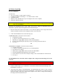
UNPACKING
Upon receipt, unpack and visually inspect the sensor. The sensor is a single metal enclosure with a
connector on one side, and with laser and sensor viewing windows on the opposite side. Ensure there is no
damage to the enclosure, connector or view windows.
The enclosed diskette contains:
DLS2000LR Setup Utility Demo Program (DLS2000LR.EXE)
SAFETY
Laser Safety
DynaVision® scanners employ one or more lasers that illuminate the measurement surface. This requires
that specific safety precautions be taken when servicing the optimizer system.
The DLS2000LR is classed by the U.S. Food and Drug Administration (FDA), Code of Federal
Regulations (CFR) 21, Part 1040, as Class IIIb. This classification is clearly marked on the DLS2000LR.
Caution! Use of controls or adjustments, or performance of procedures other than those specified herein
may result in hazardous radiation exposure.
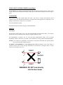
WARNING! The DLS2000LR is a Class IIIb type laser device. Regardless of the power rating, or
whether or not the laser is visible, the laser should not be viewed directly, or through a mirror, as it may
result in severe damage to the eyes.
Laser
Sensor
Laser
WARNING: DO NOT look directly
into the laser beam
5
OEM Safety Responsibilities
LMI Technologies Inc. has filed a report with the US Food and Drug Administration (FDA) to assist
OEM's in achieving certification of their own applications by referencing the report accession number. The
following paragraphs outline areas that are not covered by LMI Technologies Inc. submission and need to
be specifically addressed by the OEM.
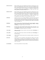
Laser Warning Sign Format
Laser warning signs must be located in the vicinity of the sensors such that they will be readily observed.
Refer to the following diagram for an example of the laser warning sign. Different warning signs are
required for different laser classifications. These are specified in the CFR Title 21, Section 1040. An
example is shown below for a Class IIIb sensor.
DANGER
INVISIBLE AND/OR VISIBLE LASER RADIATION
AVOID DIRECT EXPOSURE TO BEAM
PEAK POWER 50mW
WAVELENGTH 600-780nm
CLASS IIIB LASER PRODUCT
Laser Emission Warning Indicators
As specified by the US Food and Drug Administration, Department of Health and Human Services, Code
of Federal Regulations 21 Section 1040 (CFR 21-1040), the controls which operate the single point sensors
must incorporate a visible or audible signal when the lasers of the sensors are active. Typically this
consists of a warning lamp, which is illuminated when power is supplied to the sensor.
Additionally, CFR 21-1040 standards require that the indicator be clearly visible through protective
eyewear designed specifically for the wavelengths of the emitted laser radiation.
Beam Attenuators
CFR 21-1040 standards also specify that a permanently attached method of preventing human access to the
laser radiation other than switches, power connectors, or key control must be employed.
None of the items mentioned above are supplied with the DLS2000LR and are the
responsibility of the OEM to supply when incorporating the DLS2000LR into their system or
product.
6
USING THE DLS2000LR
The DLS2000LR can be used in a wide variety of measurement applications, including:
Object profiling
Thickness measurement
Parts inspection
Object alignment
Range measurement
On line quality control
The DLS2000LR is a ‘
smart’sensor incorporating an internal processor to handle calibration, scaling and
data conversion. The DLS2000LR provides analogue output (0-10 VDC), current output (4-20mA) and a
digital serial output (RS-485 @ 57.6kBaud).
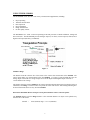
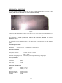
Figure 1
Standoff / Range
The distance from the reference face of the sensor to the sensor's first measurement is the Standoff. The
sensor cannot make any measurements before the Standoff. If a target is placed within this area, the
analog output would read zero voltage output, 4mA current output and the digital output will return a
-32768 indicates out of range.
The distance from the sensor's standoff to the sensor's maximum measurement point (for which it has been
calibrated) is the Range. In between these two points the sensor will return a valid reading indicating how
far the measurement surface is away from the standoff.
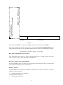
What is the maximum distance an object can be placed from the sensor's reference point?
The Standoff distance plus the Range distance is the maximum distance an object can be placed away
from the face of the sensor.
standoff
=
19.69”
(500mm) range = 118.11”
(3000mm)
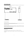
7
500mm
3000mm
Standoff
Sensor Range
Figure 2
Standoff distance (500mm) + Range distance (3000) = Object’
s Maximum Distance (3500mm)
If the object distance from the face of the sensor is greater than the Object's Maximum Distance, the
sensors analog output will read zero volts and the digital output will return a -32768 indicating out of range.
Object Distance > (Standoff + Range) => Out of Range
How do laser triangulation sensors work best?
Laser triangulation sensors work best when the measurement surface is a diffuse reflector such as the
surface of a piece of paper, wood, or non-shiny metal and plastic.
Do I need a computer to use the DLS2000LR?
No, the DLS2000LR can be used without a computer/control system using the voltage or current and/or
with a computer using RS-485 serial communication.
Without a computer:
The DLS2000LR can be employed as an analogue sensor and does not require connection to an external
computer. Connect the cable to:
a suitable power supply (see Connections)
a voltage measurement device, or
a current measurement device
8
With a computer:
The DLS2000LR can be used in a computer-based data acquisition or control system. Commands
requesting data are sent to the sensor and the sensor responds by providing range values. Commands and
data are exchanged with the DLS2000LR using a simple serial protocol (see Applications Programming).
To operate the sensor:
Connect the cable (see Multi-Drop Configurations)
Run the demonstration application DLS2000LR.EXE (enclosed diskette). This application will
display the range readings from the DLS2000LR in real time (see Getting Started
9
GETTING STARTED
Necessary Equipment
You will need:
a DC power supply ( 15VDC-30VDC @ 250mA)
an instrument capable of measuring 0 - 10 volts DC and/or 4-20mA
a flat diffuse surface
Windows 95/98 or Windows NT (if you are using the sensor with a computer)
an RS-232 to RS-485 converter
CAUTION: Always have the DC power supply turned OFF when connecting or disconnecting the
cable to the DLS2000LR.
Operating your DLS2000LR sensor is quite simple. You can use it either as a stand-alone device, or
interfaced to a personal computer through the serial communication port.
1.
Place the sensor onto a table or flat surface. Be sure that the pathway between target and the laser
window (round hole) and the camera (elongated window) is not obstructed.
2.
Connect the DLS2000LR in one of the following ways:
a. Stand-alone device. Connect the enclosed cable to:
a suitable power supply
a voltage or current measurement device (e.g. a DVM)
With the power supply OFF connect the cable to the DLS2000LR
If you are using the analogue output only, turn on your voltage measurement device.
Go to step 3.
OR
b. Interfaced to a computer. Connect the enclosed cable to:
a suitable power supply
a voltage or current measurement device (e.g. a DVM) (optional)
the serial port of a computer
With the power supply OFF connect the cable to the DLS2000LR.
Start the DLS2000LR.EXE application on the computer.
Set the software to use the correct serial port settings.. This is located under the connections tab.
Go to step 3.
The DLS2000LR can be connected to both a computer and a voltage/current-measuring device at the
same time.
WARNING: Do not look directly into the laser output window nor point it in the direction of another
person (see Safety).
3.
Position a suitable target (e.g. a cardboard box or wood block) within the measurement Range of the
DLS2000LR (see Figure 2.)
4.
Turn on the power supply to the DLS2000LR. The DLS2000LR does not have a power switch so
turning on the power supply will activate the DLS2000LR. You should now see a red laser spot on the
target and a display of the range readings on the computer screen, and/or a voltage/current reading on
the voltage/current measurement device.
10
MECHANICAL MOUNTING
The sensor enclosure contains a mounting plate with three pre-drilled mounting holes (see Figure 3.). The
accuracy of the sensor is dependent on a secure mechanical mounting.
Figure 3
Calibration of the DLS2000LR is relative to the reference face of the sensor. The minimum distance the
target can be from the reference face of the sensor is the standoff distance (see Figure 2.).
Any movement or vibration of the sensor relative to the object being measured will result in
measurement errors.
The surface the sensor is mounted to must be flat within 0.030”(0.76mm) between the three mounting
points.
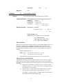
Mechanical Specifications
Dimensions
410.4mm(16.15”
) x 117.48mm(4.62”
) x 38.4mm(1.51”
)
Electrical Specifications
Power Supply Voltage
Analog Output
Maximum Analog Output Load
15 VDC - 30 VDC @ 250mA
0 VDC - 10 VDC
4mA –20mA
550Ωu
s
i
n
gc
u
r
r
e
n
tout
pu
t2000Ωu
s
i
ngv
ol
t
a
g
eou
t
pu
t
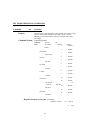
Laser Specifications
Visible Laser
Wave Length
Peak Power
(RED)
690 nm
50 mW
Performance Specifications
Standoff
Range
500mm ( 19.67”
)
3000mm (118.11”
)
Resolution (Digital):
Resolution (Analog):
Scan Rate
0.250mm (0.010”
)
0.762mm (0.030”
)
1663Hz
11
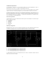
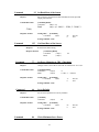
Connector Pin Out
The following diagram shows the connector pin out on the sensor as it is viewed facing the sensor. The
table details pin assignments for the Sensor Connector.
Pin
1
2
3
4
5
6
7
Signal
Rx+ (Receive)
Rx- (Receive)
Tx+ (Transmit)
Tx- (Transmit)
Out Rng
Analog 1 Out (0 –10V)
Analog 1 Common
8
9
10
Analog 2 Common
Analog 2 Out (4-20mA)
Sync
11
GND
12
POWER
Front View of
Connector of Sensor
Cable Pin Out
See pin out/wire color supplied with the cable.
Environmental
Ambient Temperature
Relative Humidity:
Housing :
Operating
MIN
MAX
Storage
MIN
MAX
0
C
(32
F)
+50
C (122
F)
-30
C (-22
F)
+70
C (158
F)
95% Maximum Non-Condensing at 40
C (104
F)
Gasket aluminum enclosure
12
SENSOR ORIENTATION
Refer to the following diagram locating the light beam and viewing angles. The light beam is projected
perpendicular to the face of the sensor.
Non-reflective materials
If the surface of the material being measured is non-reflective (e.g. wood, non-shiny metal), the sensor
should be mounted so the beam is projected perpendicular to the surface.
Semi-reflective materials
If the surface of the material being measured is semi-reflective (e.g. glossy painted surface), the sensor
should be rotated counter-clockwise to reduce the direct reflection of the beam back to the sensor. All range
readings are perpendicular to the face of the sensor
APPLICATION PROGRAMMING
General Overview
All communication between the host computer and the sensor is via an RS-485 serial interface.
All commands are initiated from the host computer to the sensor, with the sensor responding to the
commands.
13
Communications Specifications
The DLS2000LR is designed to use the RS-422/485 standard for its serial communication. This is a
differential driver/receiver pair. It is capable of transmitting up to 4000 feet.
The serial ports of most personal computers are based on the two wire RS-232 standard. To use a personal
computer as the host for a multi-drop configuration, you will need an RS-232 to RS-485 converter box.
The RS-485 option allows the sensor to be used in multi-drop configurations. This means that up to 32
units can be connected to the same serial line. Each device must have a different address so that you are
able to distinguish which unit you are talking to. A standard utility (DLS2000LR.exe) is supplied to allow
you to set the address of each DLS2000LR unit.
Interconnect Specification
Transmit and Receive lines are connected to the serial I/O port of a host computer. This serial I/O port
must be configured as follows:
Asynchronous
57600 baud.
8 Data Bits
One Stop Bit
No Parity
Multi-Drop Configurations
DLS2000LR sensors can be wired in a multi-drop configuration. The serial communication must be wired
as full duplex, meaning four wires are required to complete the hardware connection as follows:
Tx+ of all the DLS2000LR sensors are connected to the Rx+
Tx- of all the DLS2000LR sensors are connected to the RxRx+ of all the DLS2000LR sensors are connected to the Tx+
Rx- of all the DLS2000LR sensors are connected to the Tx-
A 120 termination resistor must be connected across the Tx+ and Tx-, and the Rx+ and Rx- at the end
farthest away from the host computer.
14
A utility is supplied (DLS2000LR.EXE), from which you can set the address of each DLS2000LR.
Remember that this program only works in Microsoft® Windows® environments.
Cable Power Requirements
The cable must be capable of handling +15 to 30VDC at 500 mA current.
The voltage must not drop below 14.5 VDC at the sensor.
Maintenance
Since the DynaVision® scanner heads operate optically, the primary maintenance procedure is keeping the
heads, and especially optical surfaces clean of sawdust, oil and pitch.
Do not immerse the unit in fluids and do not use a high-pressure spray to clean.
The sensor contains optical and electronic components and under no circumstances should the
enclosure be opened.
Mechanical
The sensor surface attachment should be periodically checked (once per month or as required) to ensure
that mechanical mounting is secure.
CLEANING
The glass surfaces must be kept clean from dirt and grease build up. It is recommended that the face of the
sensor be inspected and cleaned with isopropyl alcohol on a regular basis. Do Not use commercial
glass cleaners; many have chemicals that leave residue on the glass, which can affect optical
performance.
AIR PURGE SYSTEMS
In very dirty environments, where free-floating particles are present, it is advised that a positive air pressure
system be installed, such as an ‘
air knife’or ‘
blower’system. These systems blow air over the laser and
sensor glass surfaces to prevent dust particles from settling. It is important that the air be clean and free
from oil and water. The air purge system could be continuous or pulsed air operated from a timer.
15
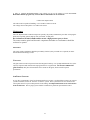
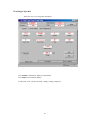
Using DLS2000LR Setup Utility
Connecting to the Sensor
Select the proper COM Port, Baud Rate (57600 - Factory Default Rate), the unit address and click on
“
Connect”button. If the unit address is not known, check the Use Global Address window and click on
“
Connect”button.
NOTE : Do not use Global Addressing in multi-drop configuration. All sensors have default address of 1.
In case of multi-drop configuration, ensure that each sensor has been assigned a unique address before
being placed on single communication line.
Serial #
The number shown here is the sensor’
s serial number which is labeled on the
front of the sensor enclosure (Factory Programmed).
Firmware
This is the firmware version of the sensor (Factory Programmed).
Model #
This is the sensor’
s model number (Factory Programmed).
FPGA
This is the sensor’
s FPGA version of the sensor (Factory Programmed).
16
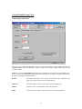
Setup Sensor Parameters
Address
The sensor address may range from 1 to 255, the maximum number of sensors
that can be placed on a multi-drop line. Each sensor must have a different
address.
To change the address of the sensor, enter new address and click on “
Address”
button.
NOTE: When changing the address, only one sensor must be communicating with the host.
Set Offset
Defines a base offset value to add to the sensor’
s range readings.
This value is added before the reading is stored in the scan buffer.
It is assumed to be within a certain range and accuracy depending on the sensor
mode.
Sets the cosine of the angle the sensor is mounted relative to the measurement
surface. For a sensor mounted with the laser beam perpendicular (90
) to the
surface, the value of 1.000 is entered.
Baud Rate
This is the sensor’
s Baud Rate that it uses to communicate to the Host. To
change Baud Rate select the Baud Rate from the list and click on “
Baud Rate”
button. The Baud rate is preset at the factory to 57600 Baud.
Error Checking
Error checking method used by sensor to communicate with the Host :
Checksum (Default) or CRC
17
To change the method, select the one from the list and click on “
Error
Checking”button.
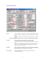
Set Scan Variables
Filter Parameters, Dropout, Smooth and Order, are used to filter the data in the
scan buffer. Reasonable values for ‘
SMOOTH’factor, ‘
ORDER’factor and
‘
DROPOUT’count are (50.0%, 3, 10) respectively.
Dropout Factor
To change the dropout factor, edit the value and Click on “
Set”
. This specifies the number of bad readings
to fill in with the last good reading if the sensor does not obtain valid readings. Dropout filter is applied to
the scan buffer before the moving average filter. Results are as follows:
Dropout Count
Result
1
No dropouts removed.
10
Any bad laser reading 10 samples wide are filled
in with previous valid data.
Order Factor
To change the order factor, edit the value and Click on “
Set”
. This item is used by the moving average filter
and the smooth factor. This number is the number of samples that are averaged, centered on the sample
being filtered. It must be odd and between 1 and 19. (i.e. An ‘
ORDER’factor of 3 uses 3 elements to
calculate the average value. An ‘
ORDER’factor of 19 causes 9 elements before and 9 elements after the
element being filtered to be used in the average calculation.)
Smooth Factor
This item modifies the smooth factor used by the scan buffer filter programs. This factor, along with the
order factor is used to apply a moving average filter to the current scan buffer. Results of the smooth are as
follows:
Smooth
Order
Results
0
X
Moving average filter is off
30.0%
5
Filtered Value = (70% current value) +
(30%* [Average of 5 samples])
A‘
SMOOTH’factor near 100% means the data buffer elements will be averaged heavily with adjacent
elements in the buffer. To change the smooth factor, edit the value and Click on “
Set”
.
Interval
This refers to the sensor’
s scan interval, i.e. the rate at which sensor stores
scanned samples in the scan buffer. To change the scan factor, edit the value and
Click on “
Set”
.
Start Scan
Starts filling the scan buffer with range readings at rate specified by “
Interval”
.
Stop Scan
Stops filling the scan buffer.
Filter
Filters the scan buffer using specified filter factors, and display high, low, and
average sample reading from the scan buffer.
Read Scan Buffer
Reads the scan buffer and store it in a file (specified by user).
18
Max Laser Power
During automatic laser power adjustment, this limits the maximum power. The
power can be adjusted from 1-254: the lower the value, the higher the laser
power. Together with “
Min Laser Power”you can setup the Laser Power range
to ensure the optimal sensor’
s performance. To change the maximum laser
power, enter the new power setting and click on “
Max Laser Power”
. The
recommended value for Max Laser Power is 2.
Min Laser Power
During automatic laser power adjustment, this limits the minimum power. The
power can be adjusted from 1-254: the higher the value, the lower the laser
power. Together with “
Max Laser Power”you can setup the Laser Power range
to ensure the optimal sensor’
s performance. To change the minimum laser
power, enter the new power setting and click on “
Min Laser Power”
. The
recommended ( Factory Defaults ) value for Min Laser Power is 240.
Threshold
This refers to the A to D converted threshold for detecting the laser spot and
filtering it through the background light. The threshold can be adjusted from 0255. The lower the value the more sensitive the camera becomes to laser light
but also becomes more sensitive to background ambient light. Recommended
value for threshold is 48.
Min Range
Sets the sensor’
s range at which the analog output is at the “
volt@min”
. For any
range less than this value, sensor will output the analog reading of “
volt @
OutOfRange”and digital reading of 65535 (FFFFh).
Max Range
Sets the sensor’
s range at which the analog output is at the “
volt at max”
. For
any range greater than this value, sensor will output the analog reading of “
volt
@ OutOfRange”and digital reading of 65535 (FFFFh).
Volt @ Min
Analog output when the object sensed is at the nearest point (“
Min Range”
) of
the sensor’
s range.
Volt @ Max
Analog output when the object sensed is at the furthest point (“
Max Range”
) of
the sensor's range.
Volt @ OutR
Voltage output when the object sensed is outside the defined “
min range”and
“
max range”
.
Set Period
This interval is the rate which the sensor updates the readings for the output
taking readings at its sample rate and averaging them. For example, a value of
‘
150.00’means that 200 readings are taken and averaged before the output will
be updated. To change this value, enter the new value in the edit box and click
on the “
Set”button
Set to Defaults
Sets all sensor parameters to factory defaults.
19
View Ranges/ Spot Info
Allows the user to view range/spot information.
Press START to continuously display spot Information
Press STOP to end continuous display.
If “
Show All”is not ‘
Checked’then only “
Range”reading is displayed.
20
COMMUNICATIONS PROTOCOL
This section describes the contents of the packet used to transmit commands and data between a host
computer and a DLS2000LR sensor.
General Packet Protocol
An asynchronous RS-485 serial communication link serves as the hardware interface between the host and
the sensor(s). The software protocol describes the packet or group of information that is transmitted.
Generally this consists of:
an address
a command
optional data
Checksum or CRC
Packet Description
A packet consists of a string of bytes. The same format is used to transmit from the host to the sensor and
back.
What is a packet's maximum size?
The maximum size of any single packet is 259 bytes. If the data block to be transmitted exceeds 259 bytes,
then the total data block must be transmitted with more than one packet. For example, if the total data
consists of 700 bytes then this will take a total of 3 packets of data to be sent.
PACKET FORMAT
[STX][Address][CommandSize][Command][Data..Data] [Checksum] or [CRC]
[STX]
1 byte
Start transmission character (02 hex)
[Address]
1 byte
0 broadcast to all sensors.
1..255 addressing a specific sensor.
Note: This byte identifies the sender when
received by the host.
[Command Size] 1 byte
Number of bytes from command to the last data
byte. Maximum 255.
[Command]
1 byte
1..255 See command descriptions.
[Data..Data]
1 byte
Number of bytes is command dependent.
[Checksum] 1 byte
OR
[CRC]
2s Complement sum of all bytes inclusive of
STX and last data byte.
2 bytes
16 bit CRC of all bytes inclusive of STX and last data byte
PACKET EXAMPLE:
To request the current range value from the sensor, the host computer program should send the following
message packet:
21
02
STX Character
address
Device Address
1
Command Size
12
Command (read)
Checksum (1 byte)
CRC (2 bytes)
NUMERIC FORMATS
The following describes the format of numbers contained within a packet.
Byte-
Always an unsigned 8 bit number 0..255.
Words-
All words used in commands data streams are signed 16 bit numbers. When using
CRC,MSB of the data Two bytes sent with a range of 0 to 65535, the least significant
byte is sent first.
Decimal points are assumed depending on data content.
Example: If the data is 12345 would represent 1234.5 mm.
COMMUNICATIONS ERROR HANDLING
This section describes the error handling of the serial communications.
The validity of the data in all packets transmitted to and from the sensor is checked using the last byte of
the packet as a Checksum or CRC.
How do I process a received data packet?
When receiving a data packet from the sensor, the host application should verify the validity of the
Checksum or CRC byte. Additionally, the application should ensure that the command value returned
matches the one sent in the request packet sent to the sensor.
What is the structure of a command packet?
Each command packet has the same structure as a data packet (see Packet Example). This means you must
terminate each command packet with a Checksum or CRC.
What if the sensor detects an error?
If the sensor detects an error in the transmission it will ignore the command and not respond. If there is no
response from the sensor within 20 ms then the host application should assume an error occurred and
retransmit the original command.
Re-Synchronizing Timing
This section describes the method of synchronizing the serial transmission between the host and the sensor.
Start of Transmission (STX)
“
STX”(Start of Transmission) character initiates packets’transmission.
How do I make sure the host and sensor are synchronized?
Allow a period of 20 ms to pass without a response from the sensor BEFORE initiating a retransmission of
the request to ensure synchronization.
22
Sensor
Upon receipt of an "STX" character, the sensor will allow a maximum of 50 ms for the complete command
packet to be transmitted by the host.
What if transmission time exceeds 50 ms?
The sensor will abort receiving the packet and start looking for another STX character.
To guarantee resynchronization of all sensors on a serial line, the host application should stop all
transmission for 200ms. After this time, all sensors on the serial line will be waiting to receive an STX
character.
Host
Upon receipt of an 'STX' character the host should allow a maximum of 500 ms for the complete response
packet to be transmitted from the sensor.
What if the complete packet is not received in 500 ms?
The host application should abort the command and start looking for another STX character.
DynaVision® APPLICATION PROGRAMMING INTERFACE
Development of application programs for the DLS2000LR is a simple task.
Requirements are:
a suitable serial interface driver
a program that reads requests and receives character data (byte stream) using the Packet Format
described in the previous paragraphs
By writing an application in the host computer, you can:
request data from the sensor
read and process data values returned from the sensor
23
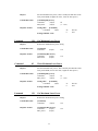
Commands
General Overview
The DLS2000LR sensor is initialized, configured and controlled by commands it receives over a high
speed RS-485 serial communications interface. The command may be a broadcast type that will be
received and acted upon by all sensors connected to that serial line, or may be addressed to a specific
sensor. The command number will dictate the response.
All commands consist of a 1 byte command value 1..255 and a number of bytes or words.
COMMAND
01
Purpose
TURN LASER ON
Sets time-out value for laser in 4 msec increments. Host must send this
command before timer expires or laser will turn off. Value is always
truncated to next closest multiple of 4 m sec
If a zero is sent then laser is turned on with no time-out.
If a –1 is sent then laser comes on at power up and there is no timeout. This is the factory
setting.
HOST COMMAND SIZE
COMMAND
DATA
-
3 BYTES
01
2 BYTES
DATA TYPE
Range
-
16 BIT WORD
0..32000 (x4 msec)
LASER TIMEOUT VALUE:
RESULT
Turns Laser On with optional time-out
Response Format
If using CRC: [Command]
Command
(Byte)
01
Success
0 Fail
02
Success
0 Fail
If using ChkSum: None.
COMMAND
02
TURN LASER OFF
HOST COMMAND SIZE 1 BYTE
COMMAND
02
DATA None
RESULT Turns laser off
Response Format
If using CRC: [Command]
Command
If using ChkSum: None.
24
(Byte)
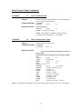
Scanning Commands
Command
05
Purpose
Command Format
Set Scan Interval
Sets the rate the sensor fills the internal sample buffer. Scan interval
indicates the number of internal clock ticks (.60 ms), which elapse
between updates. To store samples in the scan buffer use the
commands ‘
START SCAN’and ‘
STOP SCAN‘
. (see following
command descriptions).
[command] [scan interval]
Command
(1 byte)
05
scan interval
(1 word) 1 ... 32000 (x .60ms)
Response Format: if using CRC: [Command]
Command (Byte)
05
Success
0
Fail
If using ChkSum: None
Command
03
Purpose
Start Scan
Clears the scan buffer and begins sampling at the rate specified
by [Scan Interval], adding each sample in the scan buffer.
Upon receipt of the START Scan command, the sensor will
begin sampling after the time set in the SET SCAN INTERVAL
command. For example, if the scan interval was set to 1,000 (x
.60ms) or 6.0 seconds, the first sample would be entered after
6.00 seconds and every 6.0 seconds afterwards.
Command Format: [command]
command
Response Format :
(1 byte)
03
if using CRC: [Command]
Command
(Byte)
03
Success
0
Fail
If using ChkSum: None
NOTE: The maximum number of samples that can be stored is 8192 (8 Kbytes), The buffer would be full
in 163.84 seconds at a sample rate of 20 ms. When the buffer reaches capacity, samples will
wrap around and begin storing new values at the beginning of the scan buffer, overwriting
samples.
Command
04
Stop Scan
PURPOSE
Stops sampling and preserves the contents of the Scan buffer.
Command Format: [command]
25
command
Response:
Command
14
Purpose
(1 byte)
04
None
Set Scan Filter Factors
Sets up the filtering factors for the samples in the scan buffer.
Command Format: [command][dropout factor][smooth factor][order factor]
command
dropout factor
smooth factor
order factor
Response Format:
(1 byte)
14
(1 word) 1..50
(1 word) 0..100
(1 word) 1,3,5,7,9,11,13,15,17,19
(must be odd)
if using CRC: [Command]
Command
(Byte)
14
Success
0
Fail
If using ChkSum: None
NOTE: The filters are applied in the following order:
1st - Drop Out Filter.
2nd - Moving Average Filter
3rd - High / Low Sampling
Drop Out Filter
When the laser sensor returns a dropout (no value) a 32768 (8000h) sample will be put in
the buffer. The dropout filter replaces all 32768 sample scan areas with the value
preceding the dropout where the number of contiguous 32768 samples is less than the
[Dropout Factor]. If the [Dropout Factor] is set to 1 then no dropouts are filtered. For
example:
With the [Dropout Factor] = 3,
Buffer before = ..101, 102, 32768, 32768, 104, 0, 0, 0, 103...
after = ..101,102, 102, 102, 104, 0, 0, 0,103...
The [Dropout Factor] is set in the SET SCAN FILTER FACTOR command.
Moving Average (Smooth) Filter
This filter takes an average of an odd number of samples on either side of the original
sample and creates a new value by adding percentage of the average to a percentage of
the original. The filter will smooth the scan with no phase shift. Two filter factors control
these filters:
(a)
Order Factor - The number of samples to average. It must be an odd
number between 3..19. A value of 5 will cause two readings before and
two readings after to be averaged.
(b)
Smooth Factor - The percentage of the average to add to the opposite
percentage of the original sample is a percentage 0 to 100 %, e.g.:
Newsample = (average*smooth%) + (original sample*(100%-smooth%)
If smooth is 0 then no smoothing takes place.
26
Command
15
PURPOSE
Command Format
Filter Scan Buffer
Causes the contents of the scan buffer to be processed and
modified using the parameters defined by the SET SCAN
FILTER FACTORS command. This command should only be
sent after the STOP SCAN command and not while the buffer is
still being filled.
[command]
[command]
1 byte 15
Response Format:
if using CRC: [Command]
Command (Byte)
15
0
If using ChkSum: None
Success
Fail
High Low (order) Sampling
After applying the Dropout and Moving Average Filters, the scan buffer is processed to find the
location and value of the Highest sample, Lowest sample and the Average of all samples.
Command
10
Purpose
Read High / Low / Average of Scan
Obtains the High/Low and Average values of the readings contained in
the scan buffer.
Command Format
[command]
command
Response Format
(1 byte)
10
[response][high value][high scan #][low value][low scan
#][average]
response
high value
high scan#
low value
low scan#
average
(1 byte)
10
(1 word)
sensor range
(1 word) 1..8192
(1 word)
sensor range
(1 word) 1..8192
(1 word)
sensor range
NOTE:
Sensor Rangeis dependent on the actual mode of
operation. Refer to chapter 4.3.1. ‘
SET MODE’
.
27
Command
11
PURPOSE
Read Scan Buffer
Obtains the contents of a specified portion, or the entire scan buffer.
Between 1 and 66 packets is sent containing scan data. Each
packet contains up to 126 samples.
Command Format
[command] [start scan index][scans to read]
command
(1 byte)
11
start scan index (1 word) 1..8192
scans to read
(1 word) 1..8192
Response Format
[response][sequence #][scan data] (4-254 bytes)
response
sequence #
scan data
(1 byte)
11
(1 byte)
66..1 –Highest sequence
number (maximum 66) to 1. [sequence #]
starts at the high value and decrements to 1
for last packet of scan.
(1..126 Words) Always 126 except for last
packet (sequence# = 1).
NOTE: The command should be issued by the host to determine how many samples are
in the buffer before reading it. (see section 4.4.3 Read Current Sensor Status) If a large
buffer is requested the host must be capable of accepting up to 16,384 bytes into its own
buffer without losing data. If this buffer size is unavailable, smaller packets should be
requested. The scan buffer can be read as many times, as the host requires. If unfiltered
scans are required the host should read the scan buffer before requesting that the scan
buffer be filtered.
28
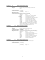
SET MODE/OPERATION COMMANDS
Command
09
Set Mode
Purpose
Sets the sensor’
s range and units of measurement. The accuracy of the
sensor’
s measurement depends on this range setting. Once the
[MODE] is set all measurement values are in inch or metric units,
accordingly.
Command Format
[command] [mode]
command
mode
(1 byte)
(1 word) 0
09
= 00.000"...
1
32.000 "
= 00.000"..-
32.000 "
2
= 0000.0...
3
= 0000.0...
4
= 000.00"...
5
= 000.00"...
6
= 00.000...
7
= 00.000...
8
= 0.0000"...
9
= 0.0000"...
10
= 000.00...
11
= 000.00...
12
3200.0 mm
-3200.0 mm
320.00 "
-320.00 "
32.000 m
-32.000
3.2000 "
-3.2000 "
320.00 mm
-320.00 mm
= 000.00...
266.00 ft
13
= 000.00...
14
= 000.00...
15
= 000.00...
-266.00 ft
320.00 m
-320.00 m
Response Format: if using CRC: [Command]
Command
(Byte)
09
Success
0
29
Fail
If using ChkSum: None
Command
08
Purpose
Set Offset/Cosine/Multiplier
Defines a base offset value to add to the sensor's range readings. This
value is added before the reading is stored in the scan buffer. It is
assumed to be within a certain range and accuracy depending on the
sensor mode. Sets the cosine of the angle the sensor is mounted relative
to the measurement surface. For a sensor mounted with the laser beam
perpendicular (90
) to the surface, the value of 1.000 is entered.
Set the multiplier of the output. The range reading is multiplied by this
value before output. Do not use as this would result in output.
COMMAND FORMAT [command] [offset] [cosine] [multiplier] [cosoffset2]
command
offset
cosine
angle
multiplier
cosoffset2
Response Format:
(1 byte)
08
(1 word)
sensor range
(1 word) 0.0000 - 1.0000 cosine of mounting
(1 word) 0.0000- 10.000
(1 word) reserved
if using CRC: [Command]
Command
(Byte)
08
Success
0
Fail
If using ChkSum: None
NOTE:
sensor rangeis dependent on the actual mode of operation. Refer to chapter 4.3.1. ‘
SET MODE’
.
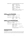
COMMAND
18
PURPOSE
Command
Set Address
Assigns a specific address to the sensor identified by the serial number.
This command is always sent as a broadcast to all sensors (packet
Address is zero). Each sensor checks the [serial #] and if it matches the
serial # stamped on the face of the sensor, the [address] is set. This
address is then used to send commands to a specific sensor (see section
2.1 Packaging).
Format [command] [serial #] [address]
command
(1 byte) 18
serial #
(8 ASCII bytes)
address
(1 byte) 1..255
Response Format:
if using CRC: [Command]
Command
(Byte)
18
Success
0
If using ChkSum: None
30
Fail
COMMAND
26
PURPOSE
Set Analog Output Factors
Sets new values for analog output, including minimum and maximum
voltage, minimum and maximum range, offset and out of range values.
Command Format
[command][Minvolt][Minrange][
Maxvolt][Maxrange][offset]
[Out of Range][reserved][d/aoutput]
command
(1 byte)
26
minvolt
(1 word) 0..9.999 Volts
minrange
(1 word)
sensor range
maxvolt (1 word) 0..9.999 Volts
maxrange
(1 word)
sensor range
offset
(1 word) 0..9.999 Volts
out of range
(1 word) 0..9.999 Volts
reserved (4 words)
0
ResponseFormat:
if using CRC: [Command]
Command
(Byte)
26
Success
0
Fail
If using ChkSum: None
Sensor Rangeis dependent on the actual mode of operation. Refer to
section 4.3.1. SET MODE. For further explanation of each parameter
see chapter 7.3.2. Change Sensor Parameters.
NOTE:
Command
33
Set Configuration Variables
Purpose
Command Format
Sets laser power and sample interval.
[command][lasercfg][laserpwr][lointerval][hiinterval][reserved]
command
(1 byte)
33
lasercfg (1 word) Reserved
laserpwr
(1 word) 0...31744
period
(2 words)
low word, high word [60,
120,180]
(x 0.01ms)
reserved (1 word) 0
Response Format:
if using CRC: [Command]
Command
(Byte)
33
Success
0
Fail
If using ChkSum: None
NOTE: For further explanation of each parameter see section
7.3.2. Change Sensor Parameters.
31
Command
92
Set Baud Rate of the Sensor
Purpose
Puts sensors to specific baud to match the RS-485 serial input and
output ports baud rate.
Command Format:
[command] [Baud]
Command
(1Byte) 92
Baud
(1Byte) (0 :
9600, 1 : 19200, 2 : 38400, 3 :
57600)
Response Format
if using CRC : [Command]
Command
(Byte)
92
0
Success
Fail
If using ChkSum : None
Command
135
Response
Get Baud Rate of the Sensor
Reads Sensors Baud setting
Response Format:
Command
77
[command ] [Baud]
Command
(1 Byte)
Baud
(1 Byte)
135
Set Error Changing to CRC / Checksum
Purpose
Changes sensor’
s error-check from CRC to Checksum or vice-versa..
Command Format:
[command][Mode]
Command
(1 Byte)
Mode
(1 Byte)
Response Format
77
0 : CRC / 1 : Chksum
if using CRC : [Command]
Command
(Byte)
77
0
Success
Fail
If using ChkSum : None
Command
66
Set to Defaults
Purpose:
Sets all sensor parameters to Factory Defaults.
Command Format:
[command]
Command
Response Format
(1 Byte)
66
if using CRC : [Command]
Command
(Byte)
If using ChkSum : None
Command
84
Write Minimum Laser Power
32
66
0
Success
Fail
Purpose
Sets the minimum laser power ( This is actually the OFF time of the
laser power PWM; so higher the value , lower the laser power. )
Command Format:
[command][Min_Power]
Command
(1 Byte)
Min_Power
(1 Byte)
Response Format
84
( 1. . 254 )
if using CRC : [Command]
Command
(Byte)
84
0
Success
Fail
If using ChkSum : None
Command
130
Get Minimum Laser Power
Purpose
Returns the minimum laser power setting.
Command Format
[Command]
Command
Response Format
Command
83
(1 Byte)
[Command] [Min. Power]
Command
(1 Byte)
Min. Power
(1 Byte)
130
130
Write Maximum Laser Power
Purpose
Sets the maximum laser power ( This is actually the OFF time of the
laser power PWM; so lower the value , higher the laser power. )
Command Format:
[command][Max_Power]
Command
(1 Byte)
Max_Power
(1 Byte)
Response Format
83
(1 . . 254)
if using CRC : [Command]
Command
(Byte)
83
0
If using ChkSum : None
Command
129
Get Maximum Laser Power
Purpose
Returns the maximum laser power setting.
Command Format
[Command]
Command
Response Format
(1 Byte)
[Command] [Max. Power]
Command
(1 Byte)
Max_Power
(1 Byte)
33
129
129
Success
Fail
Command
82
Write Threshold
Purpose
This refers to the A to D converted threshold for detecting the laser spot
and filtering it, lower the value the more sensitive camera becomes.
Command Format:
[command][Threshold]
Command
(1 Byte)
Threshold
(1 Byte)
Response Format
82
( 0 . . 255)
if using CRC : [Command]
Command
(Byte)
82
0
Success
Fail
If using ChkSum : None
Command
131
Get Threshold
Purpose
Returns the threshold value.
Command Format
[Command]
Command
Response Format
Command
134
(1 Byte)
131
[Command] [Threshold]
Command
(1 Byte)
Threshold
(1 Byte)
131
Start Streaming
Purpose
Puts the senor to streaming data mode, sensor is continuously sending
out range values until host sends any character (byte) to the sensor to
end the steaming mode.
Sensor start to send out 16 bit data of the following format:
MSB and LSB
Command Format:
[command]
Command
Command
147
(1 Byte)
134
End Streaming
Purpose
Stops the sensor from streaming data mode.
Command Format:
[command]
Command
(1 Byte)
34
147
Read Current Values Commands
Command
12
Read Current Position
Purpose
Returns the current reading in standard or metric depending on
the sensor mode with offset added.
Command Format
[command]
command
Response Format
(1 byte)
12
[response][position]
response
(1 byte)
12
position (1 word)
sensor range
NOTE:
Sensor Rangeis dependent on the actual mode
of operation. Refer to chapter 4.3.1. SET MODE.
Command
19
Read Current Sensor Setup
Purpose
Command Format
Returns Various setup parameters.
[command]
[command]
1 byte 19
Response Format
[response][serial#][address][mode][aperture][thresh
old][scantime]
[dropout][smooth][order][offset][cosine][cosoff1][cosoff2][la
ser]
response
(1 byte)
19
serial#
(8 ASCII bytes)
address
(1 byte)
1..255
mode
(1 byte)
0..3
aperture (1 word)
threshold
(1 byte)
1..255 - ignore
scantime
(1 word) 1..32000 (x 0.6 ms)
dropout
(1 word) 1..50
smooth
(1 word) 0..100 %
order
(1 word) 1..19 (odd)
offset
(1 word)
sensor range
cosine
(1 word) 0.0 - 1.0000
cosoff1
(1 word) Reserved
cosoff2
(1 word) Reserved
laser
(1 word) 0 = laser off, 1 = laser on
NOTE:
Sensor Rangeis dependent on the actual mode of operation. Refer to section 4.3.1. SET MODE.
35
COMMAND
21
Read Current Sensor Status
Purpose
Returns a variety of values relating to current sensor
status.
Command Format
[command]
[command]
1 byte
21
Response Format
sepix][sumpix][numpix][subpix][current][scancnt][scanflg]
response
(1 byte)
21
basepix
(1 word) 0..2047 - base pixel address
(ignore)
sumpix
(1 word) sum of pixels (ignore)
numpix
(1 word) width of laser spot pixels (ignore)
subpix
(1 word) sub pixel value (ignore)
current
(1 word)
sensor range- position
scancnt
(1 word) 1..8192 - number of samples
scanflg
(1 word) 0 = not scanning, 1 = scanning
NOTE:
sensor rangeis dependent on the actual mode of
operation. Refer to chapter 4.3.1. ‘
SET MODE’
. Also see
section 7.3.2.5 for description of [base pix], ext.
Command
20
Read Current Error Status
Propose
Command Format
Response Format
Command
27
Purpose
Returns various error and statistic counts.
[command]
Command
1 byte 20
[response][power][reset][chkerr][cmderr][calbrat][illopc]
response
(1 byte)
20
power
(1 word) # of power up restarts
reset
(1 word) # of restarts excluding power up
chkerr
(1 word) # of checksum errors
cmderr
(1 word) # of command errors from host
calbrat
(1 word) 5555 Hex = Calibration OK
illopc
(1 word) # of illegal opcodes
Read Analog Output Factors
Command Format
Returns various new factors for analog output.
[command]
[command]
36
1 byte 27
Response Format
[response][Minvolt][Minrange][Maxvolt][Maxrange][offset]
[Out of Range] [reserved][d/aoutput]
response
(1 byte)
27
minvolt
(1 word) 0..9.999 Volts
minrange
(1 word)
sensor range
maxvolt (1 word) 0..9.999 Volts
maxrange
(1 word)
sensor range
offset
(1 word) 0..9.999 Volts
out of range
(1 word) 0..9.999 Volts
reserved (4 words)
0
d/aoutput
(1 word )
0..4095
NOTE:
Sensor Rangeis dependent on the actual mode
of operation. Refer to Section 4.3.1 Set Mode
Command
30
Read Version Number
Purpose
Command Format
Returns internal software version number.
[command]
command
Response Format
Command
32
(1 byte)
30
[response][version][model][reserved]
response
(1 byte)
30
version
(1 word )
0...255
model
(1 word )
0...255
reserved (2 words )
0
Read Configuration Variables
Purpose
Command Format
Returns laser configuration parameters.
[command]
command
Response Format
(1 byte)
32
[response][lasercfg][laserpwr][interval][reserved]
response
(1 byte)
32
lasercfg (1 word) ignore
laserpwr (1 word) 0...31744
period
(2 words)
low word, high word
reserved (1 word) 0
NOTE: For further explanation of each parameter see chapter
7.3.2. 'Change Sensor Parameters'.
HIGH SPEED POLLING MODE
General Description
The DLS2000LR sensor is capable of a special mode, which utilizes a high speed transfer protocol enabling
range measurement in real time. When the high speed polling command is issued, the sensor changes data
transfer protocols. The protocol is a simple one. The sensor expects one of two possible ASCII characters:
37
P (50h)
Software encoder pulse. Each time the sensor receives command 50h it
responds by sending a range reading (1 word - LSB,MSB) back. The
sensor will ignore all other commands until it receives an F (46h).
F (46h)
Finish high speed poll mode. The sensor changes back to its normal data
transfer protocol.
Using the high speed polling mode the data transfer can maintain the highest sample rate possible (667 Hz)
if the baud rate has been changed to 57600 baud.
Command
35
Put Sensor In High Speed Mode
PURPOSE
Command
Response Format:
Puts the sensor in high speed polling mode and changes the
data transfer protocol.
[command]
command
(1 byte)
if using CRC :
Command
[Command]
(Byte)
35
35
0
Success
Fail
If using ChkSum : None
NOTE: The sensor will stay in the high speed polling mode
even if the sensor gets powered down and up again unless the
F character has been sent.
38
4.6
Command Summary Ordered by Command Number
Command
Description
01
Laser On
02
Laser Off
03
Start Scan
04
Stop Scan
05
Set Scan Interval
08
Set Offset
09
Set Mode
10
Read/Low/Average of Scan
11
Read Scan Buffer
12
Read Current Position
14
Set Scan Filter Factors
15
Filter Scan Buffer
18
Set Address
19
Read Current Sensor Setup
20
Read Current Error Status
21
Read Current Sensor Status
26
Set Analog Output Factors
27
Read Analog Output Factors
30
Read Version Number
32
Read Configuration Variables
33
Set Configuration Variables
35
Put Sensor in High Speed Mode
66
Set To Defaults
77
CRC/CheckSum mode
82
Write Threshold
83
Set Maximum Laser Power
84
Set Minimum Laser Power
92
Set Sensors Baud Rate
129
Get Maximum Laser Power
130
Get Minimum Laser Power
131
Get Threshold
134
Start Streaming
135
Get Baud Rate of the sensor
147
End Streaming
39
The Pseudo Code below describes a simple application program.
Pseudo Code
MainLoop
// We'll talk to any attached sensor so we 'broadcast' to sensor address 0//
// We want to read the range. Which is a command value of 12, and length 1//
WHILE (NOT Finished)
SendSensorCmd(0, 1, 12)
ReadSensorRange
ENDWHILE
// Until we're told to stop//
// Send the sensor our request//
// Read what the sensor sent//
SendSensorCmd(SensorAddress, CmdLength, CmdByte)
XmitBuffer[0] = STX
XmitBuffer[1] = SensorAddress
XmitBuffer[2] = CmdLength
XmitBuffer[3] = CmdByte
// 1st byte is always an STX char//
// the Sensor Address//
If using CheckSum or error checking then
Checksum = (STX + SensorAddress + CmdLength + CmdByte) * -1
XmitBuffer[4] = Checksum
// put it at the end //
else
for (i = 0; i < length[xmitBuffer]; i++)
{
ch = XmitBuffer[i]
for (shifter = 0x80; shifter; shifter >>= 1)
{
flag = (CRC & 0x8000)
CRC <<= 1
CRC |= ((shifter & ch) ? 1 : 0)
if (flag)
CRC ^= 0x1021
}
}
XmitBuffer[4] = CRC (MSB)
Xmitbuffer [5] = CRC (LSB)
Write(XmitBuffer, COMPORT)
StartTimeOutTimer
ReadSensorRange
//checksum //
MsgReceivedFlag = FALSE
FirstByteFlag = TRUE
// Initialize status flags//
WHILE ((NOT TimeOut) AND (MsgReceivedFlag = FALSE))
IF ByteRcvd
// Got a byte ?//
IF FirstByteFlag = TRUE
// Yes! Is it the 1st
one?//
IF ByteIn = STX
// Yes! Is it an
STX ?//
BufferPtr = 0
// Yes! Start
storing the packet//
FirstByteFlag = FALSE
40
RcvBuffer[BufferPtr] = ByteIn
BufferPtr = BufferPtr + 1
ENDIF
ELSE
// We've already got an STX so//
RcvBuffer[BufferPtr] = ByteIn
// add this byte to
the queue//
IF BufferPtr = 2
Length byte?//
RcvLength = ByteIn + 3
bytes we'll get//
BufferPtr = BufferPtr + 1
ENDIF
ENDIF
// Is this the
// Calc how many
// Update our pointer//
//CRC ReadSensorRange //
MsgReceivedFlag
XmitBuffer[4] = CRC = FALSE
WHILE ((NOT TimeOut) AND (MsgReceivedFlag <TRUE))
IF ByteRcvd
IF FirstByteFlag = TRUE
IF ByteIn = STX
FirtsByteFlag = TRUE
BufferPtr = 0
FirstByteFlag = FALSE
RcvBuffer[BufferPtr] = ByteIn
BufferPtr = BufferPtr + 1
ELSE
RcvBuffer[BufferPtr] = ByteIn
IF BufferPtr = 2
RcvLength = ByteIn + 3
BufferPtr = BufferPtr + 1
IF BufferPtr > RcvLength
StopTimeOutTimer
MsgReceivedFlag = TRUE
ENDWHILE
//* Got the Full Message ? *//
//* Yes! Stop the Timeout Timer *//
IF MsgReceivedFlag = TRUE
RcvAddr = RcvBuffer[1]
RcvCmd = RcvBuffer[3]
RcvLen = length[RcvBuffer] –2
RcvCRC/Chksum = Last one or two bytes of
RcvBuffer;
Calculate CRC or Checksum
IF RcvCRC/CheckSum <> CalcCRC/CheckSum
CRCError = TRUE
ELSE
41
IF RcvCmd <> CmdByte
CommandError = TRUE
ELSE
SensorRange = WORD(RcvBuffer[4])
ELSE
TimeOutError = TRUE
IF BufferPtr > RcvLength // Got the Full Message ?
//
StopTimeOutTimer
Timeout Timer//
MsgReceivedFlag = TRUE
- We're done//
ENDIF
ENDWHILE
IF MsgReceivedFlag = TRUE
or Timeout ? //
RcvChecksum = 0
Then validate it//
RcvAddr = RcvBuffer[1]
RcvCmd = RcvBuffer[3]
// Yes! Stop the
// Set the status flag
// Packet received
// Packet received.
FOR loopctr = 0 TO RcvLength
// Calculate the checksum//
RcvChecksum = RcvChecksum + RcvBuffer[loopctr]
IF RcvChecksum <> 0
// Is it valid?//
ChecksumError = TRUE
// No! Indicate
the error//
ELSE
IF RcvCmd <> CmdByte
// Yes! Does the response match? //
CommandError = TRUE
// No! Indicate the error//
ELSE
// Otherwise, get the
range value//
SensorRange = WORD(RcvBuffer[4])
ENDIF
ENDIF
ELSE
TimeOutError = TRUE
// Too much time passed//
ENDIF
42
TROUBLESHOOTING
This section will help you with any difficulties you may have in operating the DLS2000LR sensor.
The general rule when you encounter any problems with the sensor’
s performance is to make sure that you
have:
a clean and regulated power source
a calibrated voltage measurement device (DVM/Oscilloscope)
a computer (optional)
Make sure the windows are clean, and cables and connectors are checked.
Behavior
Laser off. (When the laser is on, a red light appears in the small circular window.)
WARNING: Do not look directly into the laser output window nor point it in the direction of another
person (see Safety).
What to do
Check to see if the power is turned on.
Check cabling and ensure power is wired correctly.
Behavior
No data comes from the sensor’
s serial port.
What to do
1.
2.
Check cabling and ensure that power and signals are wired correctly. Make sure you have an RS-232
to RS-485 converter.
Check to see that the laser is on. The DLS2000LR uses a visible (red) laser.
WARNING: Do not look directly into the laser output window nor point it in the direction of another
person (see Safety).
3.
4.
5.
6.
7.
8.
Check to see that the camera’
s field of view is not obstructed, and that the window is clean.
Connect an LED with a 3.3K-ohm resistor in series across Pins #5 - (Out of Range) and #12.
Place a target within the sensor’
s range. The LED should be lit.
Block the path between the camera and the laser. The LED should go out.
Check the analogue output with a instrument capable of measuring DC voltage from 0 to 10 (e.g.
DVM) VDC.
Move the target back and forth. Observe the analogue output. It should change as the target is moved.
If the voltage changes it is likely that your serial port configuration and/or cabling is incorrect. If the
voltage output does NOT change check your wiring again.
Behavior
No data comes from sensor’
s analogue output.
What to do
43
1.
2.
Check cabling and ensure that power and signals are wired correctly. Make sure you have an RS-232
to RS-485 converter.
Check to see that the laser is on. The DLS2000LR uses a visible (red) laser.
WARNING: Do not look directly into the laser output window nor point it in the direction of another
person (see Safety).
3.
4.
5.
6.
7.
8.
Check to see that the camera’
s field of view is not obstructed, and that the window is clean.
Connect an LED with a 3.3K-ohm resistor in series across Pins #5 - (Out of Range) and #12.
Place a target within the sensor’
s range. The LED should be lit.
Block the path between the camera and the laser. The LED should go out.
Connect the serial port of the sensor to a host computer using an RS-232 to RS-485 converter
Move the target back and forth. Observe the displayed range value on your computer. It should change
as the target is moved. If the values change and there is still no analogue output, the analogue signals
are probably incorrectly wired.
Behavior
In a multi-drop configuration, one or more sensors do not respond and do not provide data to the serial
interface.
What to do
1.
2.
Connect the offending sensor by itself (see previous) to see if it operates correctly in a non-multi-drop
environment.
If the sensor behaves correctly in #1, the problem may be that the sensor is incorrectly addressed when
used in the multi-drop configuration.
a) Be sure you are using an RS-232 to RS-485 converter.
b) Check that the wiring of the multi-drop configuration is correct (See Multi-Drop
Configurations).
c) Check that the sensor addresses you are sending are correct. Use the program DLS2000.EXE
to reset any invalid sensor addresses.
44
GETTING FURTHER HELP
If you wish further help on the DLS2000LR contact your distributor.
For more information on Safety and Laser classifications, contact:
Center for Devices and Radiological Health, FDA
Office of Compliance (HFZ-305)
Attn: Electronic Product Reports
2098 Gaither Road
Rockville, Maryland 20850
List of Agents
Canada and the United States
Call our offices at 1-604-636-1011 for the agent nearest you, or visit
our web site at www.lmint.com
EUROPE
LMI Selcom Inc.(Sweden)
phone: 46-31-336-25-10
Box 250, S-433 25
fax: 46-31-44-61-79
Ogardesvagen 19A
Partille, Sweden
45