1
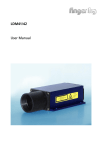
Single Point Sensor
DynaVision¤ DLS2000
User Manual
Version 1.1
2
Laser Measurement International Inc.
#205 - 7088 Venture Street
Delta, BC Canada V4G 1H5
Telephone: (604) 940-0141
Fax (604) 940-0793
Germany:
Finger GmbH & Co KG
Sapelloh 84
31606 Warmsen
Tel +49 (0)5767 96 02 0
Fax +49 (0) 5767 93004
Trademarks and Restrictions
DynaVision is a registered trademark of Laser Measurement International Inc.
This product is designated for use solely as a component and as such it does not comply with the standards
relating to laser products specified in U.S. FDA CFR Title 21 Part 1040.
Windows¤ 95, Windows¤ 98 and Windows¤ NT are registered trademarks of Microsoft¤ Corporation.
No part of this publication may be copied, photocopied, reproduced, transmitted, transcribed, or reduced to
any electronic medium or machine readable form without prior written consent of Laser Measurement
International Inc.
This product is covered under one or more of the following patents:
USA:
Canada
Germany
5,096.922
5,114.230
5,684.292
4,394.683
1,307.051
30 16 361
4375,921
5,164.579
5,691.545
5,811.827
1,116.750
31 23 703
Printed in Canada December 1999 Version 1.1
3
4,305.661
5,362.970
5,734.172
4,373.804
5,510.625
4,667.231
Australia
New Zealand
Finland
4,875.776
5,670.787
4,576.482
616.731
228.128
94551
TABLE OF CONTENTS
WELCOME TO THE DLS2000 ............................................................................................................................5
UNPACKING .........................................................................................................................................................5
SAFETY..................................................................................................................................................................5
Laser Safety ........................................................................................................................................................5
OEM Safety Responsibilities .........................................................................................................................6
Laser Warning Sign Format...........................................................................................................................6
Laser Emission Warning Indicators...............................................................................................................6
Beam Attenuators ...........................................................................................................................................6
USING THE DLS2000...........................................................................................................................................7
Figure 1 ...............................................................................................................................................................7
Standoff / Range .................................................................................................................................................7
Figure 2 ...............................................................................................................................................................8
Standoff distance + Range distance = Object s Maximum Distance ..............................................................8
Object Distance > (Standoff + Range) => Out of Range..................................................................................8
How do laser triangulation sensors work best?.................................................................................................8
Do I need a computer to use the DLS2000?......................................................................................................8
GETTING STARTED............................................................................................................................................9
Necessary Equipment .........................................................................................................................................9
MECHANICAL MOUNTING ............................................................................................................................10
Figure 3 .............................................................................................................................................................10
Mechanical Specifications................................................................................................................................10
Electrical Specifications ...................................................................................................................................10
Laser Specifications..........................................................................................................................................10
Performance Specifications..............................................................................................................................11
Serial Communication Commands ..................................................................................................................11
Environmental...................................................................................................................................................12
SENSOR ORIENTATION...................................................................................................................................12
APPLICATION PROGRAMMING ....................................................................................................................13
General Overview.............................................................................................................................................13
Communications Specifications.......................................................................................................................13
Interconnect Specification................................................................................................................................13
Multi-Drop Configurations ..............................................................................................................................13
COMMUNICATIONS PROTOCOL ..................................................................................................................13
General Packet Protocol ...................................................................................................................................14
NUMERIC FORMATS........................................................................................................................................14
COMMUNICATIONS ERROR HANDLING....................................................................................................15
What is a CRC? ................................................................................................................................................15
How do I process a received data packet? .......................................................................................................15
What is the structure of a command packet?...................................................................................................15
What if the sensor detects an error?.................................................................................................................15
Re-Synchronizing Timing ................................................................................................................................15
Start of Transmission (STX) ............................................................................................................................15
How do I make sure the host and sensor are synchronized?.......................................................................15
Sensor............................................................................................................................................................16
What if transmission time exceeds 50 ms?..................................................................................................16
Host ...............................................................................................................................................................16
What if the complete packet is not received in 500 ms?.............................................................................16
DynaVision¤ APPLICATION PROGRAMMING INTERFACE ................................................................16
Pseudo Code .....................................................................................................................................................16
MainLoop..........................................................................................................................................................16
TROUBLESHOOTING .......................................................................................................................................18
GETTING FURTHER HELP ..............................................................................................................................19
4
WELCOME TO THE DLS2000
The DLS2000 is a member of the DynaVision¤ family of laser-based ranging sensors. These sensors
employ a laser and the triangulation principle to make precise measurements of range as shown in Figure 1.
UNPACKING
Upon receipt, unpack and visually inspect the sensor. The sensor is a single metal enclosure with a
connector on one side, and with laser and sensor viewing windows on the opposite side. Ensure there is no
damage to the enclosure, connector or view windows.
The enclosed diskette contains:
DLS2000 Demo Program (DLS2000.EXE)
SAFETY
Laser Safety
DynaVision¤ scanners employ one or more lasers that illuminate the measurement surface. This requires
that specific safety precautions be taken when servicing the optimizer system.
The DLS2000 is classed by the U.S. Food and Drug Administration (FDA), Code of Federal Regulations
(CFR) 21, Part 1040, as Class IIIa. This classification is clearly marked on the DLS2000.
Caution! Use of controls or adjustments, or performance of procedures other than those specified herein
may result in hazardous radiation exposure.
WARNING! The DLS2000 is a Class IIIa type laser device. Regardless of the power rating, or whether
or not the laser is visible, the laser should not be viewed directly, or through a mirror, as it may result in
severe damage to the eyes.
Laser
Sensor
Laser
WARNING: DO NOT look directly
into the laser beam
5
OEM Safety Responsibilities
Laser Measurement International has filed a report with the US Food and Drug Administration (FDA) to
assist OEM’s in achieving certification of their own applications by referencing the report accession
number. The following paragraphs outline areas that are not covered by Laser Measurement International
submission and need to be specifically addressed by the OEM.
Laser Warning Sign Format
Laser warning signs must be located in the vicinity of the sensors such that they will be readily observed.
Refer to the following diagram for an example of the laser warning sign. Different warning signs are
required for different laser classifications. These are specified in the CFR Title 21, Section 1040. An
example is shown below for a Class IIIa sensor.
DANGER
VISIBLE LASER RADIATION
AVOID DIRECT EXPOSURE TO BEAM
PEAK POWER <5 mW
WAVELENGTH 600-710 nM
CLASS IIIa LASER PRODUCT
Laser Emission Warning Indicators
As specified by the US Food and Drug Administration, Department of Health and Human Services, Code
of Federal Regulations 21 Section 1040 (CFR 21-1040), the controls which operate the single point sensors
must incorporate a visible or audible signal when the lasers of the sensors are active. Typically this
consists of a warning lamp which is illuminated when power is supplied to the sensor.
Additionally, CFR 21-1040 standards require that the indicator be clearly visible through protective
eyewear designed specifically for the wavelengths of the emitted laser radiation.
Beam Attenuators
CFR 21-1040 standards also specify that a permanently attached method of preventing human access to the
laser radiation other than switches, power connectors, or key control must be employed.
None of the items mentioned above are supplied with the DLS2000 and are the responsibility
of the OEM to supply when incorporating the DLS2000 into their system or product.
6
USING THE DLS2000
The DLS2000 can be used in a wide variety of measurement applications, including:
•
•
•
•
•
•
Object profiling
Thickness measurement
Parts inspection
Object alignment
Range measurement
On line quality control
The DLS2000 is a smart sensor incorporating an internal processor to handle calibration, scaling and data
conversion. The DLS2000 provides analogue output (0-10 VDC), current output (4-20mA) and a digital
serial output (RS-485 @ 57.6kBaud).
Triangulation Principle
Object A Detected here
Object B Detected here
CCD Array
DLS2000
LASER
Lens
Laser Beam
As the distance from the
sensor to the object changes,
the light from the object is
detected at a different pixel
on the CCD array.
Object at Position A
Object at Position B
Figure 1
Standoff / Range
The distance from the reference face of the sensor to the sensor’s first measurement is the Standoff. The
sensor cannot make any measurements before the Standoff. If a target is placed within this area, the
analog output would read zero voltage output, 4mA current output and the digital output will return a
-32768 indicates out of range.
The distance from the sensor’s standoff to the sensor’s maximum measurement point (for which it has been
calibrated) is the Range. In between these two points the sensor will return a valid reading indicating how
far the measurement surface is away from the standoff.
What is the maximum distance an object can be placed from the sensor’s reference point?
The Standoff distance plus the Range distance is the maximum distance an object can be placed away
from the face of the sensor.
7
Figure 2
Standoff distance + Range distance = Object s Maximum Distance
If the object distance from the face of the sensor is greater than the Object’s Maximum Distance, the
sensors analog output will read zero volts and the digital output will return a -32768 indicating out of range.
Object Distance > (Standoff + Range) => Out of Range
How do laser triangulation sensors work best?
Laser triangulation sensors work best when the measurement surface is a diffuse reflector such as the
surface of a piece of paper, wood, or non-shiny metal and plastic.
The DLS2000 is a smart sensor incorporating an internal processor to handle calibration, scaling and data
conversion. The DLS2000 provides analogue output (0-10 VDC), current output (4-20mA) and a digital
serial output (RS-485 @ 57.6kBaud).
Do I need a computer to use the DLS2000?
No, the DLS2000 can be used without a computer/control system using the voltage or current and/or with a
computer using RS-485 serial communication.
Without a computer:
The DLS2000 can be employed as an analogue sensor and does not require connection to an external
computer. Connect the cable to:
•
•
•
a suitable power supply (see Connections)
a voltage measurement device, or
a current measurement device
With a computer:
8
The DLS2000 can be used in a computer-based data acquisition or control system. Commands requesting
data are sent to the sensor and the sensor responds by providing range values. Commands and data are
exchanged with the DLS2000 using a simple serial protocol (see Applications Programming). To operate
the sensor:
•
•
Connect the cable (see Multi-Drop Configurations)
Run the demonstration application DLS2000.EXE (enclosed diskette). This application will display
the range readings from the DLS2000 in real time (see Getting Started).
GETTING STARTED
Necessary Equipment
You will need:
•
•
•
•
•
a DC power supply ( 15VDC-30VDC @ 250mA)
an instrument capable of measuring zero 0 - 10 volts DC and/or 4-20mA
a flat surface
Windows 3.1, Windows 95 or Windows NT (if you are using the sensor with a computer)
an RS-232 to RS-485 converter
Caution: Always have the DC power supply turned OFF when connecting or disconnecting the cable to
the DLS2000.
Operating your DLS2000 sensor is quite simple. You can use it either as a stand-alone device, or interfaced
to a personal computer through the serial communication port.
1.
Place the sensor onto a table or flat surface. Be sure that the pathway between target and the laser
window (round hole) and the camera (elongated window) is not obstructed.
2. Connect the DLS2000 in one of the following ways:
a. Stand-alone device connect the enclosed cable to:
•
a suitable power supply
•
a voltage or current measurement device (e.g. a DVM)
•
With the power supply OFF connect the cable to the DLS2000
•
If you are using the analogue output only, turn on your voltage measurement device.
•
Go to step 3.
OR
b. Interfaced to a computer connect the enclosed cable to:
• a suitable power supply
• a voltage or current measurement device (e.g. a DVM) (optional)
• the serial port of a computer
• With the power supply OFF connect the cable to the DLS2000.
• Start the DLS2000.EXE application on the computer.
• Set the software to use the correct serial port settings.. This is located under the connections tab.
• Go to step 3.
The DLS2000 can be connected to both a computer and a voltage/current-measuring device at the
same time.
9
NOTE
: Do not look directly into the laser output window nor point it in the direction of another person
(see Safety).
3.
Position a suitable target (e.g. a cardboard box or wood block) within the measurement Range of the
DLS2000 (see Figure 2.)
4.
Turn on the power supply to the DLS2000. The DLS2000 does not have a power switch so turning on
The power supply will activate the DLS2000. You should now see a red laser spot on the target and a
display of the range readings on the computer screen, and/or a voltage/current reading on the
voltage/current measurement device.
MECHANICAL MOUNTING
The sensor enclosure contains a mounting plate with three pre-drilled mounting holes (see Figure 3.). The
accuracy of the sensor is dependent on a secure mechanical mounting.
Figure 3
Calibration of the DLS2000 is relative to the reference face of the sensor. The minimum distance the target
can be from the reference face of the sensor is the standoff distance (see Figure 2.).
Any movement or vibration of the sensor relative to the object being measured will result in
measurement errors.
The surface the sensor is mounted to must be flat within 0.030 (0.76mm) between the three mounting
points.
Mechanical Specifications
Dimensions
184.4mm x 98.6mm x 38.4mm
Electrical Specifications
Power Supply Voltage
Analog Output
Maximum Analog Output Load
15 VDC - 30 VDC @ 250mA
0 VDC - 10 VDC
4mA — 20mA
550 V using current output 2000V using voltage output
Laser Specifications
Visible Laser
(RED)
10
Wave Length
Laser Power
670 nm
< 5 mw
Performance Specifications
Standoff
Range
Accuracy
Resolution (Digital):
Resolution (Analog):
Scan Rate
100mm
300mm
0.025mm (0.001 )
0.075mm (0.003 )
1800Hz
Serial Communication Commands
(For complete packet protocol see Applications Programming section)
Read Current Position
Purpose:
Returns the current reading in millimeters.
Command Format:
[command]
Read command
12 (single byte, binary)
Response Format:
[response][position]
response (1 byte) 12
position (1 word)
+/- <sensor range>
Example:
Send:
Response:
12
12
Data Value
Optional Supplied Cable Pin Out Environmental
See pin out/wire color supplied with the cable.
11
Environmental
Ambient Temperature
Operating
MIN
MAX
Storage
MIN
MAX
0 8 C (32 8 F)
+50 8 C
(122 8 F)
-30 8 C (-22 8 F)
+70 8 C
(158 8 F)
Relative Humidity:
95% Maximum Non-Condensing at 40 8 C (104 8 F)
Housing :
Gasket aluminum enclosure
SENSOR ORIENTATION
Refer to the following diagram locating the light beam and viewing angles. The light beam is projected
perpendicular to the face of the sensor.
Incorrect
Correct
Non-reflective materials
If the surface of the material being measured is non-reflective (e.g. wood, non-shiny metal), the sensor
should be mounted so the beam is projected perpendicular to the surface.
Semi-reflective materials
12
If the surface of the material being measured is semi-reflective (e.g. glossy painted surface), the sensor
should be rotated counter-clockwise to reduce the direct reflection of the beam back to the sensor.
APPLICATION PROGRAMMING
General Overview
All communication between the host computer and the sensor is via an RS-485 serial interface.
All commands are initiated from the host computer to the sensor, with the sensor responding to the
commands.
Communications Specifications
The DLS2000 is designed to use the RS-422/485 standard for its serial communication. This is a
differential driver/receiver pair. It is capable of transmitting up to 4000 feet.
The serial ports of most personal computers are based on the two wire RS-232 standard. To use a personal
computer as the host for a multi-drop configuration, you will need an RS-232 to RS-485 converter box.
The RS-485 option allows the sensor to be used in multi-drop configurations. This means that up to 32
units can be connected to the same serial line. Each device must have a different address so that you are
able to distinguish which unit you are talking to. A standard utility is supplied to allow you to set the
address of each DLS2000 unit.
Interconnect Specification
Transmit and Receive lines are connected to the serial I/O port of a host computer. This serial I/O port
must be configured as follows:
•
•
•
•
•
Asynchronous
57600 baud.
8 Data Bits
One Stop Bit
No Parity
Multi-Drop Configurations
DLS2000 sensors can be wired in a multi-drop configuration. The serial communication must be wired as
full duplex, meaning four wires are required to complete the hardware connection as follows:
INSERT DIAGRAM (MULTI.DOC)
•
•
•
•
Tx+ of all the DLS2000 sensors are connected to the Rx+
Tx- of all the DLS2000 sensors are connected to the RxRx+ of all the DLS2000 sensors are connected to the Tx+
Rx- of all the DLS2000 sensors are connected to the Tx-
A 120V termination resistor must be connected across the Tx+ and Tx-, and the Rx+ and Rx- at the end
farthest away from the host computer.
A utility is supplied (DLS2000.EXE), from which you can set the address of each DLS2000. Remember
that this program only works in Microsoft¤ Windows¤ environments.
COMMUNICATIONS PROTOCOL
13
This section describes the contents of the packet used to transmit commands and data between a host
computer and a DLS2000 sensor.
General Packet Protocol
An asynchronous RS-485 serial communication link serves as the hardware interface between the host and
the sensor(s). The software protocol describes the packet or group of information that is transmitted.
Generally this consists of:
• an address
• a command
• optional data
• a CRC
Packet Description
A packet consists of a string of bytes. The same format is used to transmit from the host to the sensor and
back.
What is a packet’s maximum size?
The maximum size of any single packet is 259 bytes. If the data block to be transmitted exceeds 259 bytes,
then the total data block must be transmitted with more than one packet. For example, if the total data
consists of 700 bytes then this will take a total of 3 packets of data to be sent.
PACKET FORMAT
[STX][Address][CommandSize][Command][Data..Data][CRC]
[STX]
1 byte
[Address]
1 byte
Start transmission character (02 hex)
0 broadcast to all sensors.
1..255 addressing a specific sensor.
Note: This byte identifies the sender when
received by the host.
[Command Size] 1 byte
Number of bytes from command to the last data
byte. Maximum 255.
[Command]
1 byte
1..255 See command descriptions.
[Data..Data]
1 byte
Number of bytes is command dependent.
[CRC]
1 byte
2s Complement sum of all bytes inclusive of
STX and last data byte.
PACKET EXAMPLE:
To request the current range value from the sensor, the host computer program should send the following
message packet:
02
STX Character
address
Device Address
1
Command Size
12
Command (read)
NUMERIC FORMATS
The following describes the format of numbers contained within a packet.
14
CRC
Byte-
Always an unsigned 8 bit number 0..255.
Words-
All words used in commands data streams are signed 16 bit numbers. Two bytes sent
with a range of 0 to 65535, the least significant byte is sent first.
Decimal points are assumed depending on data content.
Example: If the data is 12345 would represent 1234.5 mm.
COMMUNICATIONS ERROR HANDLING
This section describes the error handling of the serial communications.
The validity of the data in all packets transmitted to and from the sensor is checked using the last byte of
the packet as a CRC.
What is a CRC?
The CRC is the 2’s complement of the sum of all bytes in the packet, excluding the CRC byte itself.
Adding the sum of all the bytes to the CRC should result in a value of zero.
How do I process a received data packet?
When receiving a data packet from the sensor, the host application should verify the validity of the CRC
byte. To do this, add the sum of all bytes (excluding the CRC) to the CRC in the received message.
Additionally, the application should ensure that the command value returned matches the one sent in the
request packet sent to the sensor. A non-zero result indicates an error.
What is the structure of a command packet?
Each command packet has the same structure as a data packet (see Packet Example). This means you must
terminate each command packet with a CRC.
What if the sensor detects an error?
If the sensor detects an error in the transmission it will ignore the command and not respond. If there is no
response from the sensor within 20 ms then the host application should assume an error occurred and
retransmit the original command.
Re-Synchronizing Timing
This section describes the method of synchronizing the serial transmission between the host and the sensor.
Start of Transmission (STX)
Transmission of packets is initiated by the "STX" (Start of Transmission) character.
How do I make sure the host and sensor are synchronized?
Allow a period of 20 ms to pass without a response from the sensor BEFORE initiating a retransmission of
the request to ensure synchronization.
15
Sensor
Upon receipt of an "STX" character, the sensor will allow a maximum of 50 ms for the complete command
packet to be transmitted by the host.
What if transmission time exceeds 50 ms?
The sensor will abort receiving the packet and start looking for another STX character.
To guarantee resynchronization of all sensors on a serial line, the host application should stop all
transmission for 200ms. After this time, all sensors on the serial line will be waiting to receive an STX
character.
Host
Upon receipt of an ’STX’ character the host should allow a maximum of 500 ms for the complete response
packet to be transmitted from the sensor.
What if the complete packet is not received in 500 ms?
The host application should abort the command and start looking for another STX character.
DynaVision¤ APPLICATION PROGRAMMING INTERFACE
Development of application programs for the DLS2000 is a simple task.
Requirements are:
• a suitable serial interface driver
• a program that reads requests and receives character data (byte stream) using the Packet Format
described in the previous paragraphs
•
By writing an application in the host computer, you can:
• request data from the sensor
• read and process data values returned from the sensor
The Pseudo Code below describes a simple application program.
Pseudo Code
MainLoop
//*
We’ll talk to any attached sensor so we ’broadcast’ to sensor address 0,
We want to read the sensor range which has a command value of 12, and length 1 *//
WHILE (NOT Finished)
SendSensorCmd(0, 1, 12)
ReadSensorRange
ENDWHILE
16
SendSensorCmd(SensorAddress, CmdLength, CmdByte)
XmitBuffer[0] = STX
XmitBuffer[1] = SensorAddress
XmitBuffer[2] = CmdLength
XmitBuffer[3] = CmdByte
CRC = (STX + SensorAddress + CmdLength + CmdByte) * -1
Write(XmitBuffer, COMPORT)
StartTimeOutTimer
ReadSensorRange
MsgReceivedFlag
XmitBuffer[4] = CRC = FALSE
WHILE ((NOT TimeOut) AND (MsgReceivedFlag <> TRUE))
IF ByteRcvd
IF FirstByteFlag = TRUE
IF ByteIn = STX
FirtsByteFlag = TRUE
BufferPtr = 0
FirstByteFlag = FALSE
RcvBuffer[BufferPtr] = ByteIn
BufferPtr = BufferPtr + 1
ELSE
RcvBuffer[BufferPtr] = ByteIn
IF BufferPtr = 2
RcvLength = ByteIn + 3
BufferPtr = BufferPtr + 1
IF BufferPtr > RcvLength
//* Got the Full Message ? *//
StopTimeOutTimer
//* Yes! Stop the Timeout Timer *//
MsgReceivedFlag = TRUE
ENDWHILE
IF MsgReceivedFlag = TRUE
RcvCRC = 0
RcvAddr = RcvBuffer[1]
RcvCmd = RcvBuffer[3]
FOR loopctr = 0 TO RcvLength
RcvCRC = RcvCRC + RcvBuffer[loopctr]
IF RcvCRC <> 0
CRCError = TRUE
ELSE
IF RcvCmd <> CmdByte
CommandError = TRUE
ELSE
SensorRange = WORD(RcvBuffer[4])
ELSE
TimeOutError = TRUE
17
TROUBLESHOOTING
This section will help you with any difficulties you may have in operating the DLS2000 sensor.
Before following the suggestions be sure that you have:
•
•
•
a clean and regulated power source
a calibrated voltage measurement device (DVM/Oscilloscope)
a computer (optional)
Behavior
Laser off.
(When the laser is on, a red light appears in the small circular window - do not look at the laser.)
What to do
•
•
Check to see if the power is turned on.
Check cabling and ensure power is wired correctly.
Behavior
No data comes from the sensor s serial port.
What to do
1.
2.
3.
4.
5.
6.
7.
8.
Check cabling and ensure that power and signals are wired correctly. Make sure you have an RS-232
to RS-485 converter.
Check to see that the laser is on. The DLS2000 uses a visible (red) laser. Do not look into the laser
exit window.
Check to see that the camera s field of view is not obstructed, and that the window is clean.
Connect an LED with a 3.3K ohm resistor in series across Pins #5 - (Out of Range) and #12.
Place a target within the sensor s range. The LED should be lit.
Block the path between the camera and the laser. The LED should go out.
Check the analogue output with a instrument capable of measuring DC voltage from 0 to 10 (e.g.
DVM) VDC.
Move the target back and forth. Observe the analogue output. It should change as the target is moved.
If the voltage changes it is likely that your serial port configuration and/or cabling is incorrect. If the
voltage output does NOT change check your wiring again.
Behavior
No data comes from sensor s analogue output.
What to do
1.
2.
3.
4.
5.
6.
7.
Check cabling and ensure that power and signals are wired correctly. Make sure you have an RS-232
to RS-485 converter.
Check to see that the laser is on. The DLS2000 uses a visible (red) laser. Do not look into the laser
exit window.
Check to see that the camera s field of view is not obstructed, and that the window is clean.
Connect an LED with a 3.3K ohm resistor in series across Pins #5 - (Out of Range) and #12.
Place a target within the sensor s range. The LED should be lit.
Block the path between the camera and the laser. The LED should go out.
Connect the serial port of the sensor to a host computer using an RS-232 to RS-485 converter
18
8.
Move the target back and forth. Observe the displayed range value on your computer. It should change
as the target is moved. If the values change and there is still no analogue output, the analogue signals
are probably incorrectly wired.
Behaviour
In a multi-drop configuration, one or more sensors do not respond and do not provide data to the serial
interface.
What to do
1.
2.
Connect the offending sensor by itself (see previous) to see if it operates correctly in a non-multi-drop
environment.
If the sensor behaves correctly in #1, the problem may be that the sensor is incorrectly addressed when
used in the multi-drop configuration.
a) Be sure you are using an RS-232 to RS-485 converter.
b) Check that the wiring of the multi-drop configuration is correct (See Multi-Drop
Configurations).
c) Check that the sensor addresses you are sending are correct. Use the program DLS2000.EXE
to reset any invalid sensor addresses.
GETTING FURTHER HELP
If you wish further help on the DLS2000 contact your distributor.
For more information on Safety and Laser classifications, contact:
Center for Devices and Radiological Health, FDA
Office of Compliance (HFZ-305)
Attn: Electronic Product Reports
2098 Gaither Road
Rockville, Maryland 20850
19