1
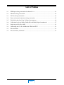
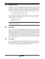
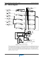
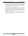
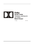
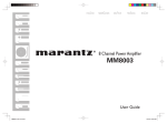
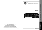
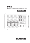
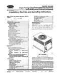
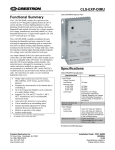
Dolby
Model 737 Soundtrack
Loudness Meter – Leq(m)
Users’ Manual
Issue 3
MAIN
Part No. 91533
Dolby Laboratories Inc
www.dolby.com
United States
100 Potrero Avenue
San Francisco, CA 94103-4813
Telephone 415-558-0200
Facsimile 415-863-1373
United Kingdom
Wootton Bassett
Wiltshire SN4 8QJ England
Telephone (44) 1793-842100
Facsimile (44) 1793-842101
WARNING: Troubleshooting must be performed by trained technicians. Do not
attempt to service this equipment unless you are qualified to do so.
DISCLAIMER OF WARRANTIES: Equipment manufactured by Dolby Laboratories is warranted against defects in materials and workmanship for a period
of one year from the date of purchase. All warranties, conditions or other terms implied by statute are excluded to the fullest extent allowed by law.
LIMITATION OF LIABILITY: It is understood and agreed that Dolby Laboratories’ liability whether in contract, in tort, under any warranty, in negligence
or otherwise shall not exceed the cost of repair or replacement of the defective components and under no circumstances shall Dolby Laboratories be
liable for incidental, special, direct, indirect or consequential damages (including but not limited to damage to software or recorded audio or visual material), or loss of use, revenue or profit even if Dolby Laboratories or its agents have been advised, orally or in writing, of the possibility of such damages.
Dolby and the double-D symbol are registered trademarks of Dolby Laboratories.
W01/111
©2000 Dolby Laboratories Inc; all rights reserved.
MAIN
Table of Contents
List of Figures .........................................................................................................................v
List of Tables ..........................................................................................................................vi
Chapter 1
Introduction ............................................................................................... 1-1
Chapter 2
Operation and Features ...................................................................... 2-1
2.1
Front Panel Controls ................................................................................ 2-1
2.1.1 6/4 – 2 Channel Switch ................................................................ 2-2
2.1.2 Input Trimpots ............................................................................. 2-2
2.1.3 Trip Set......................................................................................... 2-2
2.1.4 Pushbuttons .................................................................................. 2-2
2.2
Back Panel Connectors ............................................................................ 2-3
2.2.1 Analog Audio Inputs.................................................................... 2-3
2.2.2 Mon Out ....................................................................................... 2-4
2.2.3 DC Out ......................................................................................... 2-4
2.2.4 Power and Control ....................................................................... 2-5
2.3
Connection and Calibration ..................................................................... 2-5
2.3.1 Connecting to an Audio Console ................................................. 2-5
2.3.2 Connecting to a Dolby Cinema Processor ................................... 2-6
2.3.3 Connecting to a DA10/20 Digital Adapter .................................. 2-6
2.3.4 Connecting to Non-Dolby Digital Adapters ................................ 2-7
2.3.5 Connecting to the SDU4 Surround Decoder................................ 2-7
2.3.6 Calibration Procedure .................................................................. 2-7
2.3.7 Automated Input Adapter Board (Cat. No. 448B)....................... 2-8
2.4
Mains Power ............................................................................................ 2-9
2.5
Interface ................................................................................................... 2-9
2.6
Block diagram........................................................................................ 2-10
iii
MAIN
Chapter 3
Chapter 4
Cat. No. 448B Input Adapter Board .............................................. 3-1
3.1
Introduction.............................................................................................. 3-1
3.2
Logic map ................................................................................................ 3-1
3.3
Component and Connector Layout .......................................................... 3-2
3.4
Preview Theatre ....................................................................................... 3-2
3.4.1 Concept ........................................................................................ 3-2
3.4.2 Installation.................................................................................... 3-2
3.4.3 Alignment .................................................................................... 3-3
3.5
Dubbing studio......................................................................................... 3-4
Specifications .......................................................................................... 4-1
Appendix A Background ............................................................................................. A-1
A.1 Loudness ................................................................................................. A-1
A.2 How Loud Is a Movie? ........................................................................... A-3
A.3 Standardizing a Measurement Technique for Soundtrack “Loudness”.. A-4
A.4 Analysis of the Data................................................................................ A-6
iv
MAIN
List of Figures
2-1
Model 737 front panel .................................................................................................... 2-1
2-2
Detail of front panel controls .......................................................................................... 2-1
2-3
Model 737 back panel ..................................................................................................... 2-3
2-4
Audio input connectors (detail of rear panel) ................................................................. 2-3
2-5
Mon and DC Out, and power/control connector ............................................................ 2-4
2-6
Model 737 block diagram ............................................................................................. 2-10
3-1
Cat. No. 448B Interface Adapter .................................................................................... 3-2
3-2
Installation of Cat. No. 448B .......................................................................................... 3-2
3-3
Typical UK setup ............................................................................................................ 3-4
3-4
Cat. No. 448B Interface Adapter schematic ................................................................... 3-7
A-1
Peak levels of photographic soundtrack formats. .......................................................... A-2
A-2
A-weighting vs. CCIR-weighting curve (offset by 5.6 dB) ........................................... A-5
A-3
CCIR-weighting (Leq(m)) shows influence of 2–6 kHz region. ................................... A-6
A-4
Comparison of weighted and un-weighted Leq. ............................................................ A-7
A-5
Comparison of Leq(m) and peak levels ......................................................................... A-8
A-6
Peak levels in reel 4 of Shine ......................................................................................... A-8
A-7
Comparison of Leq(m) with peak levels for UK commercials ...................................... A-9
v
MAIN
List of Tables
2-1
XLR input wiring convention for channels 1-6 ............................................................. 2-3
2-2
Mon Out wiring convention ........................................................................................... 2-4
2-3
DC Out wiring convention ............................................................................................. 2-4
2-4
Power and control connector wiring convention ........................................................... 2-5
2-5
DA10/20 Audio Out Conn. J8 Signal Assignments ...................................................... 2-6
2-6
Calibration levels for Dolby, Dolby SR, and Dolby Digital soundtracks ..................... 2-7
3-1
Logic map of Cat. No. 448B .......................................................................................... 3-1
3-2
Connecting the Cat. No. 448B to the CP65 and CP55 .................................................. 3-3
3-3
Pin convention ............................................................................................................... 3-3
3-4
Pin convention (continued) ............................................................................................ 3-3
vi
MAIN
Model 737 Soundtrack Loudness Meter - Leq(m)
Chapter 1
Introduction
Leq(m) is a term used by Dolby Laboratories to describe the level of annoyance in movie soundtracks. The Leq(m) value is a weighted true average of the audio power level
sent to the camera in optical or digital soundtracks, or the same weighted true average of
the audio power level passing through a cinema processor before equalization. The Dolby Model 737 Soundtrack Loudness Meter – Leq(m) provides a convenient method
of measuring soundtrack annoyance.
The phrase true average signifies that the meter measures the power at regular intervals,
adds these quantities together and then divides the result by the length of the measurement time. Since the measurement time is a critical factor in arriving at an accurate result, the measurement should start and stop at known points. These points can range
from the First Frame of Action (FFOA) and Last Frame of Action (LFOA) of a spot,
such as a ten-second clip, to the beginning and end of an entire movie. The degree of
repeatability of Model 737 measurements is dependent on the length of the measurement. For example, a ten-second spot requires about two frame accuracy whereas a
two-minute-thirty-second trailer needs only two-second accuracy for correct measurement. For an entire feature, the measurement can be started and stopped at a convenient
time, within two minutes of the opening and closing credits, to get repeatable results.
Measurements made within 1% of the stated time frame will compare accurately.
The Model 737 consists of six input channels with setup trims followed by five weighting filters, a true averaging power meter that can be remotely started and stopped, and a
trip circuit that indicates a preset maximum level has been exceeded. The unit is intended
for use on soundstages, optical recording facilities, and film QA installations to audition
the final two- and six-channel mixes that will be recorded on the film. It can also be
used in theatres to check levels during exhibition.
Note: See Appendix A – Background for a complete discussion of the factors that led
to the creation of the Model 737 Soundtrack Loudness Meter – Leq(m).
1-1
MAIN
Model 737 Soundtrack Loudness Meter - Leq(m)
Chapter 2
Operation and Features
The Model 737 Soundtrack Loudness Meter – Leq(m) is a simple 1U, rack-mountable
device that measures the equivalent loudness of one-, two-, four-, or six-channel inputs,
typically from the non-equalized outputs of a cinema processor or mixing console.
Since the time available for averaging is several hours, a soundtrack can be evaluated
in small sections or in its entirety. The current Leq(m) value is displayed in the LED
window. The circuit consists of a set of six input stages, five CCIR (2K) filters, five
square law detectors, and a display driver that takes the average of the squared signal
voltage and then extracts the square root/log of the resultant DC signal. A separately
processed average DC circuit outputs a signal that is buffered for use with a chart recorder/
moving coil meter for trend analysis.
The Trip Set adjustment sets the level that lights the Trip LED and triggers a signal
to the Trip Output. The Trip Output can activate a more noticeable device (such as
a light or sound) to alert the user that a preset level has been exceeded at the end of
the measurement.
Front Panel Controls
The front panel has three pushbuttons (Cal, Start, Stop), a two-digit LED that displays
the current Leq(m) value, a screwdriver-accessible hex switch to set the trip level, trimpots for the six analog inputs, and a 6/4 – 2 channel switch.
Leq (m)
Cal
85
Stop
Trip
23
01
Trip
456
C
7 8 9A
Model 737
Start
EF
Soundtrack Loudness Meter -- Leq (m)
-
+ 6/4 - 2
L
C
R Ls Rs Sw Mon
BCD
Set
Figure 2-1 Model 737 front panel
The right side of the front panel is shown in detail below.
Stop
Cal
Start
Stop
Trip
01
23
-
456
C
7 8 9A
Trip
EF
Cal
Audio Input Trimpots
Mon Out Trimpot
Calibration LEDs
+ 6/4 - 2
L
C
R Ls Rs Sw Mon
BCD
2.1
Set
Start
Trip Set
6/4 - 2 channel switch
Figure 2-2 Detail of front panel controls
2-1
MAIN
Model 737 Soundtrack Loudness Meter - Leq(m)
2.1.1
Operation and Features
6/4 – 2 Channel Switch
Located to the left of the input trimpots (see Figure 2-2), this switch may be used in
future versions to introduce a fixed offset in the measurement of two-channel encoded
material. Presently (version 1), the offset is set to zero so the switch has no effect on
the measurement.
2.1.2
Input Trimpots
To derive accurate and repeatable Leq(m) measurements, the input trimpots are used to
calibrate the Model 737 to standard input levels. The input trimpots are screwdriveradjustable and allow sensitivity adjustments from -12 to +4 dBu for Dolby Level to suit
a wide variety of console setup levels and cinema processor types. See Section 2.3 Connection and Calibration for a complete discussion of how to connect and calibrate
the Model 737 to different signal sources.
2.1.3
Trip Set
Trip Set is a 16-position switch that sets a value from 78 Leq(m) at position 0 to 92 Leq(m)
at position E in 1 unit increments. When Stop is pressed to end the measurement, if the
Trip Set level has been exceeded, the Trip LED lights and a signal is sent to Trip Out.
The Trip LED does not light during the measurement to allow transient Leq(m) values
to exceed the Trip Set value without triggering Trip Out.
Note: The Trip circuit can be disabled by setting the switch to position F.
The current Trip level can be checked by holding down the Cal button then pressing
and holding the Stop button. This test always sends a signal to Trip Out to check the
circuit operation. Push the Run button to cancel the trip indication. In position F, the
display is blank.
2.1.4
Pushbuttons
•
Cal – Push to enter calibration mode to set audio input levels using the trimpots. In calibration mode, Mon Out sends a mono mix of the channels instead
of the output of the filter. Push Start to return to measurement mode.
•
Start – Push to begin a measurement.
•
Stop – Push to stop a measurement and display the final level of the measurement.
2-2
MAIN
Model 737 Soundtrack Loudness Meter - Leq(m)
2.2
Operation and Features
Back Panel Connectors
Ch 1
Lt
Ch 3
Ch 2
Rt
Ch 4
Dolby and the double-D symbol are trademarks of Dolby Laboratories.
Ch 5
Dolby Laboratories Inc.
AC In ~
Gnd
24Vac
500mA
AC In ~
DC Out
Subwoofer
Right Surround
Ref
Left Surround
Right
Center
Start / Stop
Mon Out
Analog Audio Inputs
Left
Gnd
Trip Out
The back panel has six audio input connectors (shown in detail in Figure 2-4), two output
connectors, and a power/control signal connector (shown in detail in Figure 2-5).
San Francisco U.S.A.
Wootton Bassett U.K.
Model 737
Ch 6
WARNING:
No user serviceable parts inside.
Refer all service
to qualified
personnel.
Figure 2-3 Model 737 back panel
2.2.1
Analog Audio Inputs
Although the input stages of Left, Center, Right, and Left Surround are identical, it is
recommended that Left and Right (Ch 1 and Ch 3, also labeled Lt and Rt, respectively)
be used for Lt/Rt measurements of two-channel encoded material. The Right Surround
and Subwoofer channels share a common filter and rectifier so the Subwoofer input is
not normally used except when measuring 5.1-channel material.
Analog Audio Inputs
Ch 1
Lt
Ch 2
Ch 3
Rt
Ch 4
Dolby and the double-D symbol are trademarks of Dolby Laboratories.
Subwoofer
Right Surround
Left Surround
Right
Center
Left
Ch 5
Ch 6
Figure 2-4 Audio input connectors (detail of rear panel)
The XLR input connectors for channels 1–6 use the following wiring convention:
Table 2-1 XLR input wiring convention for channels 1-6
Pin
Connection
1
Chassis
2
Audio +
3
Audio -
2-3
MAIN
Model 737 Soundtrack Loudness Meter - Leq(m)
AC In ~
AC In ~
24Vac
500mA
Gnd
DC Out
Ref
Mon Out
Gnd
Trip Out
Mon Out
Start / Stop
2.2.2
Operation and Features
Model 737
Figure 2-5 Mon and DC Out, and power/control connector
Mon Out is an unbalanced output which, in calibration mode, provides an unweighted
mono mix of channels. In measurement mode, Mon Out carries a mono mix of the outputs
of the weighting filters. Listening to the filtered output can help the mixer find the effect
or equalizer setting that is raising the average above the standard. Mon Out is adjustable
on the front panel from -20 to 0 dBu for Dolby Level so that it can be balanced with the
studio monitor level.
Mon Out uses the following wiring convention:
Table 2-2 Mon Out wiring convention
Pin
2.2.3
Connection
1
Chassis
2
Mon signal out
3
Mon signal common
DC Out
DC Out is an unbalanced output to drive an optional moving coil meter/chart recorder.
Using a 1 mA moving coil meter with a calibrating potentiometer across its terminals
is a useful method to observe measurement trends. DC Out uses the following wiring
convention:
Table 2-3 DC Out wiring convention
Pin
Connection
1
Chassis
2
DC out
3
DC return
1 V is equivalent to 91 Leq(m); the range is 0–1.25 VDC; 0 VDC corresponds to
70 Leq(m); output resistance is 1 kΩ.
2-4
MAIN
Model 737 Soundtrack Loudness Meter - Leq(m)
2.2.4
Operation and Features
Power and Control
The 8-pin power and control connector uses the following wiring conventions for the
control and AC power signals:
Table 2-4 Power and control connector wiring convention
Pin
Connection
1
Close to stop (+)
2
Close to stop (gnd)
3
Trip indicator (+)
4
Trip indicator (gnd)
5
Vref
6
24 VAC
7
Chassis ground
8
24 VAC
The trip output is a simple open collector buffer that passes current when the trip value
is exceeded. The voltage on the open trip contacts should not exceed 24 VDC and the
current passed when closed should not exceed 20 mA.
2.3
Connection and Calibration
The Model 737 may derive its input from a variety of signal sources including an audio
console, a cinema processor, the SDU4 Surround Decoder, the DA10/20 Digital Adapters,
and non-Dolby digital adapters. The Model 737 accurately measures both matrix-encoded
two-channel and decoded four- and six-channel sources. The following three important
points are independent of the signal source:
•
Dolby Level should be used as the test signal input level. In the digital domain,
Dolby Level correlates to -20 dBFS (20 dB below Full-Scale digital).
•
The calibration for each input must be performed with only that input connected.
When that input is calibrated, unplug it and plug in the next input to calibrate.
All inputs are connected after the calibration in preparation for the actual
measurement.
The calibration procedure is discussed in section 2.3.6. The following sections discuss
how to interface the Model 737 to the most commonly used signal sources.
2.3.1
Connecting to an Audio Console
Connect the Left, Center, Right, Left Surround, Right Surround, and Subwoofer outputs
from the audio console into the appropriate inputs on the Model 737. Use a 1 kHz tone at
Dolby Level as the test signal to each full-band input. Use a Dolby Level tone at approximately 100 Hz for the Subwoofer input.
2-5
MAIN
Model 737 Soundtrack Loudness Meter - Leq(m)
2.3.2
Operation and Features
Connecting to a Dolby Cinema Processor
The method for connecting a Dolby cinema processor with the Model 737 depends on
the application. For a cinema processor used in a studio or dubbing stage, the matrixencoded Lt and Rt signals are found on the Cat. No. 150E card. If the connection for
measurement is occasional, use the red and green test points, respectively. For more
permanent installations, connect to pins L and J on the rear panel of the cinema processor.
For a cinema processor used in a theatre, the Lt and Rt signals are found on the red and
green test points (ground is black), respectively, on the Cat. No. 150E or Cat. No. 150F.
The Cat. No. 150D does not have test points. Thread up and play a length of Cat. No. 69T
test film at Dolby Level as the signal source. Set the unit to Format 04 for the calibration
steps that follow in section Section 2.3.6 - Calibration Procedure.
Note: Alignment in Format 05 or mono will result in incorrect levels.
2.3.3
Connecting to a DA10/20 Digital Adapter
When checking levels in a theatre or print-checking facility, the Model 737 derives its
input signals directly from the J8 connectors on the back of the DA10/20. The following
table lists the CP Audio Out Conn. J8 pin number signal assignments and the nearest
ground pin.
Table 2-5 DA10/20 Audio Out Conn. J8 Signal Assignments
Output
Active
Ground
Left
14
9
Center
20
12
Right
17
11
Left Surround
15
10
Right Surround
2
1
Subwoofer
24
13
For each channel, the active pin of the output is wired to pin 2 and the ground to pin 3
of that channel’s XLR connector. If the units are in the same rack, there should be a
connection between the metal parts of the Model 737 and the digital adapter. If the
Model 737 is not in the same rack, there must be a connection between any of the
ground pins (1, 4–13) of J8 and one of the ground pins on the 8-pin power and control
connector on the rear panel of the Model 737.
When used in a theatre to check released prints, thread up and play a length of Cat. No. 69T
(US) SR.D test film at Dolby Level as the signal source (Cat. No. 1012 is still available
but seldom used).
2-6
MAIN
Model 737 Soundtrack Loudness Meter - Leq(m)
2.3.4
Operation and Features
Connecting to Non-Dolby Digital Adapters
With the digital adapter connected to the Dolby cinema processor, make a parallel connection from the cinema processor to the audio inputs on the Model 737, and use the test
media from that manufacturer as the signal source to apply Dolby Level to each channel.
2.3.5
Connecting to the SDU4 Surround Decoder
The Model 737 can interface with the SDU4 either before or after decoding. To measure
the matrix-encoded signal, connect the signals intended for the SDU4’s Lt and Rt inputs
to the Lt and Rt inputs (channels 1 and 3) on the Model 737.
To measure the decoded signal, connect the four-channel L, C, R, S outputs from the
SDU4 to the Left, Center, Right, and Left Surround inputs on the Model 737.
2.3.6
Calibration Procedure
To obtain an accurate Leq(m) measurement, the input trimpots must be used to calibrate
the inputs to standard levels to account for the differing levels and formats of the various
signal sources. Use the table below to determine the calibration setting and follow the
steps below to calibrate the inputs.
Table 2-6 Calibration levels for Dolby, Dolby SR, and Dolby Digital soundtracks
Dolby (Format 04)
Dolby SR (Format 05)
Dolby Digital
(Format 10)
Channel
Level
(dB)
Channel
Level
(dB)
Channel
Level
(dB)
Lt (matrix encoded)
85
Lt (matrix encoded)
88
L
85
Rt (matrix encoded)
85
Rt (matrix encoded)
88
C
85
L (matrix decoded)
85
L (matrix decoded)
88
R
85
C (matrix decoded)
85
C (matrix decoded)
88
Ls
82
R (matrix decoded)
85
R (matrix decoded)
88
Rs
82
S (matrix decoded)
85
S (matrix decoded)
88
Sw
85
1.
Press the Cal button.
2.
Send the appropriate test signal at Dolby Level to the first input only. Connect
only one input at a time when calibrating.
3.
Adjust the input trimpot associated with that input until the + and - LEDs beside
the trims are of approximately equal brightness (null point) and the Leq(m) value
displayed is correct according to Table 2-6.
2-7
MAIN
Model 737 Soundtrack Loudness Meter - Leq(m)
Operation and Features
Notes:
The null circuit has two points of transition (at 82 and 85), so the + and - LEDs
should be used in conjunction with the numerical display to set the correct levels
for that input.
Since the null points are only at 82 and 85, to align to 88, reduce the test tone
level to exactly 3 dB below Dolby Level and align to a null point at 85.
The window of equal illumination is designed to be extremely narrow, which
yields an accurate level setting when both LEDs are on, albeit dimly (the gain
error is less than 0.1 dB).
4. Unplug the calibrated input and repeat the calibration procedure for all other
input channels, one at a time.
5.
6.
As a final check, plug in all inputs and send the appropriate tone to all applicable
channels. The meter should register an Leq(m) value of:
88 - Dolby (Lt/Rt)
91 - Dolby Digital, Dolby SR (Lt/Rt), and Dolby (LCRS) soundtracks
94 - Dolby SR (LCRS)
Repeat the calibration if there is a significant discrepancy.
Note: The 3 dB difference between L, C, R and the surround channels matches the
transfer levels for Dolby Digital movie soundtracks.
2.3.7
Automated Input Adapter Board (Cat. No. 448B)
An additional input adapter board is available for UK-type installations that provides
channel switching and level calibration specific to the format under measurement.
The card follows a logic source from either a Dolby Cinema processor (i.e., CP65),
the DS4-E mkII (UK), or a custom control to switch between formats. Re-calibration
and re-plugging is then avoided except for normal periodic alignment checks
(see Chapter 3 – Cat. No. 448B Input Adapter Board).
2-8
MAIN
Model 737 Soundtrack Loudness Meter - Leq(m)
2.4
Operation and Features
Mains Power
The Model 737 uses a mains transformer that converts incoming AC to 24 VAC. The
transformer has 1 meter leads and should be placed at the base of the equipment rack in
which the unit is mounted. The transformer should not be operated with the 24 V leads
shorted. Transformer units are available for 200–240 VAC input and 100–125 VAC input.
Please ensure that the correct transformer is ordered for your local mains voltage.
•
For 110 VAC, Dolby part number is 54058
•
For 230 VAC, Dolby part number is 54057
In some countries, the primary cable for the module may not have a mains plug fitted.
These unterminated leads must be properly wired to a mains plug in accordance
with the following international code:
•
Brown wire: Live or hot
•
Blue wire:
Neutral
CAUTION: If you are uncertain about the wiring of your mains outlet do not use it.
Consult a qualified electrician.
2.5
Interface
The connections for remote start/stop control are normally wired to a relay across the
projector motor or to a console-mounted toggle switch. When the contacts close or the
Stop button is pressed, the display flashes the last measured value. When the contacts
open again, or the Start button is pressed, the unit enters measurement mode. Pressing
the Cal button causes the unit to enter calibration mode, regardless of the last function
pressed. To remotely start a measurement from calibration mode, the contacts must
close and then open again. The contacts should be capable of passing 10 mA and should
not have contact with other circuits. A simple toggle switch or a pair of uncommitted
relay contacts is ideal.
2.5.1
Grounding
There is no connection between the audio common inside the unit and the metalwork.
For most grounding schemes, a link of 16 AWG between pins 4 and 7 of the power/
control connector provides a satisfactory grounding scheme. If this induces hum because of a loop via the rack mounting, the link can be removed.
2-9
MAIN
Model 737 Soundtrack Loudness Meter - Leq(m)
2.6
Operation and Features
Block diagram
Monitor Out
L / Lt
in in +
CCIR
Filter
Rectifier
+
X
-
2
in C
in +
Ls
in -
CCIR
Filter
Rectifier
+
2
X
-
in +
in R / Rt
in +
CCIR
Filter
in Sub
Rs
Rectifier
+
2
X
-
in +
in -
CCIR
Filter
in +
Rectifier
+
2
X
-
Rectifier
CCIR
Filter
+
2
X
-
Rectifier and
LED Driver
(fine level)
DC out
Lt
Average
Square
Root
A/D
Start
Average
7
3
Hex
Trip Level Switch
Cal
Logic
Display
Driver
Run
Trip point out
Hold
Remote
Start/Stop
Figure 2-6 Model 737 block diagram
The six input channels each have a balanced to unbalanced stage buffering the input signal. Trimpots on the front panel set each channel’s input level. The unbalanced signals
then pass to the metering CCIR filters and make-up gain stages. The signals on the
“wipers” of the selector switch, controlled by the Mon trimpot, are buffered and sent to
Mon Out on the rear panel.
2-10
MAIN
Model 737 Soundtrack Loudness Meter - Leq(m)
Operation and Features
The selection switches are followed by five ideal rectifiers and squaring circuits. The
five squared signals are added and short term averaged. The resultant varying DC signal
passes to an analog long-term averaging circuit. This requires a logic signal from the
pushbutton logic section to start and stop the average measurement. The analog longterm averaged DC signal is sent to the DC Out connector on the rear panel for optional
connection to a chart recorder or moving coil meter.
The short-term average DC voltage is converted to12-bit binary and sent to a 6805
processor that also averages, but over a much longer time span. The samples are taken
at 850 msec intervals, summed, divided by the time since the Start button was pressed,
and then converted to a square-root value. This value is then converted to a dB (log)
scale, scaled to a reference level of 85, and sent to the front panel LED display. When
the Stop button is pressed, the averaging circuit and averaging routine are reset while
the last value measured is displayed.
The pushbutton logic is a simple tri-stable gate that drives the LEDs in the pushbuttons
and also generates processor interrupts to indicate mode changes. It is remoted to the
back panel via a single start-stop line.
2-11
MAIN
Model 737 Soundtrack Loudness Meter - Leq(m)
Chapter 3
Cat. No. 448B Input Adapter Board
3.1
Introduction
The Cat. No. 448B is an input adapter board that mounts to the rear of a CP65. The card
will suitably switch and adapt signals from a two- or six-track source following logic control from the CP65, CP55, or DS4-E (UK). Format calibration and routing requirements
are therefore met automatically.
The Cat. No. 448B passes six balanced channels on to the Model 737 with a 3-dB L
and R channel attenuation. The Model 737 is then calibrated to compensate for this
attenuation with 3 dB more gain on the L and R input trim pots. When Format 05
(Dolby SR) is selected, the attenuation is switched out giving the required 3 dB gain on
Lt/Rt for this format. In addition, when either matrix formats are selected (Format 04
or 05), the C, Ls, Rs, and Sw channels are muted. This concept is appropriate for most
studio applications assuming that Lt /Rt exist on monitor buses 2/3 or 1/3. Input jumpers
are available to switch between the two.
The Cat. No. 448B can switch an auxiliary two-track input (i.e., Optical from Cat. No.
150) to the Model 737 and pass this auxiliary signal to the DS4-E (UK) auxiliary meter
input, normalized for Dolby Level. This increases the versatility of the board to cope
with varying installation requirements from the studio through preview and optical
transfer facilities.
Note: Refer to Figure 3-4 Cat. No. 448B Interface Adapter schematic on page 3-7.
3.2
Logic map
Table 3-1 shows the logic map of the Cat. No. 448B. X = switch closed; O = switch open.
Table 3-1 Logic map of Cat. No. 448B
6/2
Aux
in
-3 dB
(DS4-E
meter)
No
2
Yes
Yes
Dolby SR (Aux in)
X
Yes
2
Yes
No
Dolby A (Aux in)
X
O
No
2
No
Yes
Dolby SR (6-trk in)
X
X
O
Yes
2
No
No
Dolby A (6-trk in)
X
O
X
O
Yes
6
No
No
Dolby Digital
O
O
X
O
No
6
No
Yes
Dolby Digital (0 dB)
SR Sw1 Sw2 Sw3ab
Sw3cd
-3 dB
Sw4cd (6-trk in)
MAT
OPT
0
0
0
O
X
O
X
0
0
1
X
X
O
0
1
0
O
X
0
1
1
X
1
1
1
1
1
0
3-1
MAIN
Format
Model 737 Soundtrack Loudness Meter - Leq(m)
3.3
Cat. No. 448B Input Adapter Board
Component and Connector Layout
R23
D1
C2 C5
J3
SW
2
L+
L-
C+
C-
R+ RLs+ Ls- Rs+ RsTO MODEL 737
C3
SW
4
IC2
Sw+ SwR26
R20
R27
C1 C4
SW
3
R1 R3R2
R4
RIGHT
RV2
IC1
RV1
R5
LEFT
Lt, Rt
1&3
(LK1-4)
R6R8 R7
LK
1
Lt, Rt
2&3
(LK1-4)
L+
LK
2
L-
LK
3
C+
R9
R1
0
R1
1
R1
2
R1
3
R1
4
R21
SW
1
LK
4
FROM DA20 / MON BUSS
CR+ RLs+ Ls- Rs+ Rs-
Sw+ Sw-
R25
R19
R24
R15
R17
R18
R16
R22
TO DS4E
Lt
Rt
SIG
GND
FROM
CAT150
Lt
Rt
OPT MAT SR
R28
R29
+15 -15
J2
0V
J1
CAT. NO. 448B
INTERFACE ADAPTOR FOR MODEL 737
A2A7463 REV A
Figure 3-1 Cat. No. 448B Interface Adapter
3.4
Preview Theatre
3.4.1
Concept
The DA10 or DA20 feeds six Dolby Digital channels; the Cat. No. 150 supplies two.
Since the DA10/20 output is unbalanced, the positive tags should be used and the negative
tags grounded. To ensure that the auxiliary two-track input is used in matrix mode, the
MAT and OPT logic lines should be paralleled together and fed from the CP65 logic.
Additionally, the SR logic line should be permanently grounded to disable the 3 dB
attenuation on L, R of the six-track input to ensure sufficient gain.
3.4.2
Installation
D A 1 0/2 0
x6 (u nbalanced)
CP65
x2 (L t/R t - o pt)
C a t. N o. 4 48 B
M od el 73 7
Figure 3-2 Installation of Cat. No. 448B
1.
Before mounting the Cat. No. 448B, ensure the jumpers LK1-4 are in the upper
(1&3) position.
2.
Connect the Cat. No. 448B with the cinema processor using Table 3-2 and
adhere to the pin conventions in Table 3-3 and Table 3-4.
3-2
MAIN
Model 737 Soundtrack Loudness Meter - Leq(m)
Cat. No. 448B Input Adapter Board
Table 3-2 Connecting the Cat. No. 448B to the CP65 and CP55
Cat. No. 448B
CP65
CP55
From Cat. No. 150 Lt
J7 pin L
J12 pin 10
From Cat. No. 150 Rt
J7 pin J
J12 pin 7
MAT & OPT logic lines
J13 pin W
J6 pin W
SR logic line
0 V (on 448B)
0 V (on 448B)
+15 V
J2 pin 5
J15 pin 5
-15 V
J2 pin 13
J15 pin 13
0V
J2 pin 9
J15 pin 9
Table 3-3 Pin convention
A
B
C
D
E
F
H
J
K
L
M
N
P
R
S
T
U
V
W
X
Y
Z
1
2
3
4
5
6
7
8
9
10
11
12
13
14
15
16
17
18
19
20
21
22
Table 3-4 Pin convention (continued)
3.4.3
AA
BB
CC
DD
EE
FF
23
24
25
26
27
28
3.
Mount the Cat. No. 448-B to the CP65 back plane using the spacers provided.
4.
Use Table 2-5 to connect the DA10/20 to the positive tags on the Cat. No. 448B
and ground all the negative tags to a 0 V tag on the Cat. No. 448B.
5.
Connect the Cat. No. 448B output to the Model 737.
Alignment
1.
Thread up and play a length of Cat. No. 69T (US) or Cat. No. 1012 with the
cinema processor placed in Format 10 - Dolby Digital. Connect each channel
to the Model 737 in turn and align the Model 737 in calibration mode for a nullpoint at 85 dB (L,C,R, Sw) and 82 dB (Ls, Rs) for each channel.
2.
Thread up and play a length of Cat. No. 69T with the cinema processor in
Format 01 - Mono and check that the calibration of the optical pre-amp card
is normal.
3.
Select Format 04 - Dolby Stereo. Connect each channel to the Model 737 in
turn (L, R) and adjust RV1 (L) and RV2 (R) trim pots of the Cat. No. 448B to
obtain a null-point at 85 dB for each channel.
4.
Check that the Model 737 reads 3 dB higher when in Format 05 than in Format 04
for each channel.
3-3
MAIN
Model 737 Soundtrack Loudness Meter - Leq(m)
3.5
Cat. No. 448B Input Adapter Board
Dubbing studio
Dubbing Studio set-ups may vary depending upon location. Contact a Dolby sound
consultant or Dolby office to resolve any uncertainties. Installation of the Cat. No. 448B
can be optimized using the logic map in Table 3-1 and Figure 3-4, the Cat. No. 448B
schematic diagram. The following examples are two common configurations.
Example 1
A typical UK setup uses the DA20 or dubbing interface (Cat. No. 448) output switched
to the CP65-S. The Cat. No. 448B should take this unbalanced six-track signal as the main
input (grounding the negative inputs) and the two-track signal from the Cat. No. 150
via the auxiliary input. OPT and MAT should be fed from either the FA line of the
CP65 or the MAT line of the dubbing interface and SR should be grounded. Follow
the installation steps in Section 3.4.2 on page 2. The six-track input is paralleled from
the 300 mV input to the CP65 after any switching between the monitor bus and DA20.
6 p 2w S w itch er
C at. N o . 4 4 8
x6 (u n b al.)
D A 1 0 /2 0
x6 (u n b al.)
CP65
x6 (b a l.)
x2 L t/R t - o pt
C at. N o . 4 4 8 B
M od e l 73 7
S tud io m o n itor b u s
Figure 3-3 Typical UK setup
Example 2
The six-track main inputs are balanced and the two-track inputs are derived from the
main input channels 1&3 or 2&3. OPT, MAT, and SR lines are fed from the dubbing
interface. The DA20 output should be routed at the calibrated level to the main monitor
buses of the studio before the dubbing interface.
CP65
C a t. N o . 4 48
x6 (un b al.)
x2 L t/R t - opt
x6 (ba l.)
C a t. N o . 4 48 B
S tu d io m o nito r b uss
3-4
MAIN
M od el 73 7
Model 737 Soundtrack Loudness Meter - Leq(m)
Cat. No. 448B Input Adapter Board
Follow these steps to install the devices used in this example:
1.
Isolate the mains power to the processor and remove the existing dubbing interface (Cat. No. 448); leave all connections to it in place.
2.
Completely remove and discard the Cat. No. 448-MS and re-route the OPT logic
line back to the OPT tag of the Cat. No. 448.
3.
Determine whether Lt/Rt default to studio record/monitor buses 2&3 or 1&3.
If Lt/Rt default to 2&3; place the links LK1-4 in the lower position. If 1&3,
place LK1-4 in the upper position.
4.
Make the following connections before mounting the Cat. No. 448B (see Table
3-3 and Table 3-4 for pin conventions):
Cat. No. 448B
5.
CP65
CP55
From Cat. No. 150 Lt
J7 pin L
J12 pin 10
From Cat. No. 150 Rt
J7 pin J
J12 pin 7
+15 V
J2 pin 5
J15 pin 5
-15 V
J2 pin 13
J15 pin 13
0V
J2 pin 9
J15 pin 9
Mount the Cat. No. 448B to the CP65 back panel using the spacers provided
and then make the following connections:
Cat. No. 448B
Cat. No. 448
MAT logic line
MAT logic line
OPT logic line
OPT logic line
SR logic line
SR logic line
DS4-E (UK)
From DA20/Mon Bus tags
Balanced six-track
inputs
To DS4-E Lt/Rt tags
Lt/Rt OPT OUT tags
6.
Connect the Cat. No. 448B output to the Model 737.
7.
Mount the dubbing interface (Cat. No. 448) on top of the Cat. No. 448B.
3-5
MAIN
Model 737 Soundtrack Loudness Meter - Leq(m)
3.5.1
Cat. No. 448B Input Adapter Board
Alignment
1.
Set the DS4-E into Discrete mode (one green LED).
2.
Send tone at Dolby Level to the studio monitor bus and align the Model 737 as
described in Section 2.3.6 - Calibration Procedure (Dolby Digital).
Note: If LK1-4 are in the lower position, the L & C input trimpots on the
Model 737 will be reversed.
3.
Set the DS4-E into Matrix Monitor mode with the SR/A or Proc 2 switch not
illuminated.
4.
Ensure the DS4-E meter is in direct mode (rear toggle switch up) and the red
rotary switch on the Cat. No. 291 of the DS4-E is set to Lt/Rt position.
5.
Send tone at Dolby Level to Lt/Rt (-6 dB on DS4-E meter) and check Model 737
for 85 per channel.
6.
Select SR on the DS4-E (SR/A or Proc 2 switch illuminated) and check Model 737
for 88 per channel.
7.
Place the DS4-E meter to Monitor position (rear toggle switch in down position)
and adjust the rear trim pots on the meter for -6 dB per channel (the DS4-E must
be in SR mode).
8.
Thread up and play a length of Cat. No. 69T and insure alignment of Cat.
No. 240A.
9.
Set the DS4-E in Matrix, A, and Optical mode and adjust RV1(L) and RV2(R)
for a null point of 85 per channel on the Model 737.
10. Set the DS4-E in Matrix, SR, and Optical mode and check that the Model 737
reads 3 dB higher on each channel.
3-6
MAIN
Model 737 Soundtrack Loudness Meter - Leq(m)
Cat. No. 448B Input Adapter Board
Figure 3-4 Cat. No. 448B Interface Adapter Schematic
3-7
MAIN
Model 737 Soundtrack Loudness Meter - Leq(m)
Chapter 4
Specifications
Temperature and Humidity
Operating
10o C to 35o C, natural convection cooling
Non-Operating (Storage)
0o C to 70o C
Humidity
Up to 90% relative humidity, non-condensing
EMC Limits
AC power line conducted
Per EN 55022
Radiated
Per EN 55022
Immunity
Per EN 50082-1
General
Dimensions
19 x 7.8 x 1.75 inches (43 x 20 x 4.5 cm)
Net Weight
≅6 lb (3 kg)
Power Requirements
24 VAC, 500 mA wall transformer (provided)
Power Consumption
10 WAC max.
4-1
MAIN
Model 737 Soundtrack Loudness Meter - Leq(m)
Appendix A
Background
This Appendix is an edited version of a paper published in the January 1998 SMPTE Journal (Volume 107, Number
1) entitled “Are Movies Too Loud” by Ioan Allen. The complete paper is available from the Dolby website at
www.dolby.com/movies. Reprints of the paper are available by sending email to [email protected] (include the article
title) or by calling 415-558-0200.
Over the past few years, the film production community has become increasingly
concerned that movies are getting louder. In addition, movie-goers often complain that
movies are too loud and, as a result, many theatres now reduce the audio fader below the
calibration level used in the dubbing theatre.
This chapter introduces some of the issues that motivated the creation of the Dolby
Model 737 Soundtrack Loudness Meter - Leq(m):
A.1
•
What factors affect soundtrack “loudness?”
•
How can loudness be quantified?
•
Do new sound formats (Dolby SR, Dolby SR·D, Sony SDDS, and DTS) exacerbate
the problem?
Loudness
Those familiar with movie soundtracks won’t be surprised at the subjective statement
that The Right Stuff (1983; Dolby A-type 70 mm and Dolby A-type stereo optical) was
a loud movie. The Right Stuff was a subjectively louder movie than Shine (1996, Dolby
Digital). Since Shine was subjectively louder than Days of Heaven (1978), perhaps a
case could be made that movies have been getting both louder and quieter! Of course,
this does not lead to an objective assessment; selected titles can be used to prove either
trend. Gone with the Wind (1939) could be used to argue that films have become quieter
over the last six decades!
A.1.1
The Current Situation
In the mid-1970s, Dolby Laboratories introduced a calibration recommendation for
monitor levels in movie soundtracks. A pink noise reference signal was used in the
record chain to adjust the audio monitor level to 85 dBc. All theatres equipped for playback of the new stereo optical soundtracks were set up such that an equivalent pink
noise signal would generate the same 85 dBc with the playback fader set to the calibrated setting. This meant that theatres playing films at the calibrated fader setting (fader 7
on most cinema processors) would reproduce the same volume level selected by the
film director and audio engineers in the dubbing theatre.
A-1
MAIN
Model 737 Soundtrack Loudness Meter - Leq(m)
Background
This system worked quite well for many years. Dolby Stereo (A-type encoded) films
had limited headroom and the resulting constrained dynamic range yielded few audience
complaints. Most theatres played films at the calibrated level. Soundtrack format technology has been significantly enhanced since Dolby Stereo. Dolby SR extended the
headroom by 3 dB at midrange frequencies, and more at low and high frequencies. In
recent years, the new digital formats have further increased the headroom (Figure A-1).
dB
120
110
100
90
80
70
60
50
40
30
20
10
0
31.5
63
125
Academy mono
250
500
1k
Dolby A-type
2k
4k
Dolby SR
8k
16k
Hz
Dolby Digital
Figure A-1 Peak levels of photographic soundtrack formats.
Because the 85 dBc calibration technique has been maintained throughout these format
changes, additional headroom is available on the newer soundtracks. Feature films have
one consistent, subjective mix reference for dialogue record level, known as “associative
loudness.” When the dubbing mixer sees an actor on the screen, and there is no “fight”
with music or effects, the dialogue level in a moderate close-up is set to be plausible for
the visual. Within reasonable limits, this holds true to within 2 or 3 dB. This natural
dialogue level does not hold true for narration, as there is no corresponding visual
reference. Music and effects have no direct visual associative loudness. Most people
are not familiar with the actual sound pressure levels of a Concorde take-off or a 50 mm
howitzer. The music score level is equally uncalibrated.
As the headroom capability of the recording medium has been extended, it has certainly
been used: the “non-associative” loudness of effects and music has risen to fill the
available space. The discretionary use of this increased headroom would be justified
and desirable on some feature films, such as “ride” and action movies.
A-2
MAIN
Model 737 Soundtrack Loudness Meter - Leq(m)
Background
In practice, the following undesirable symptoms have arisen:
•
There are an increasing number of audience complaints that movies are too
loud. Newspaper articles have been written on the subject and respected sound
mixers have spoken publicly about the problem.
•
Theatres are playing films substantially below the calibrated level. A fader level
of 5, as opposed to the calibrated level of 7, is not uncommon, representing a
level reduction of approximately 6 dB.
•
Trailers are fighting for competitive loudness. Theatre playback levels are often
set by complaints generated by the loudest (and earliest) element of the show.
If the playback level is set in response to the loudest trailer, the feature often
plays at the same reduced level. The result is that the dialogue level of the
feature is lowered by the same level deemed necessary to attenuate the trailer.
A feature film played 6 dB below the calibrated level may have serious dialogue
intelligibility problems.
•
Mix engineers are using ear plugs to avoid the risk of hearing damage.
•
In Europe, where commercials are played before the feature, competitive
loudness has led to the desire for a uniform measurement technique, and a selfdisciplined constraint.
It is possible that the increased use of headroom from Dolby A-type to Dolby SR and
digital releases has not been matched by a corresponding increase in power amplifier
and loudspeaker capability. The resultant distortion from overloaded equipment may
well exacerbate the loudness problems of recent soundtracks, causing increased incidence
of complaints.
A.2
How Loud Is a Movie?
Loudness is an extremely subjective term and has been defined and measured in many
different ways. Various definitions have arisen from a desire to quantify loudness in
specific situations:
•
How annoying is the background noise level in a working space?
•
How damaging is sustained, high-level noise exposure?
•
How intrusive is the noise level of a recording or transmission medium?
•
How can the instantaneous loudness of different spectra be compared?
In attempting to measure the loudness of a movie or trailer soundtrack, conventional
level meters in the recording chain are of only marginal help. A VU meter has slow time
constants, and is of little use in detecting short-term peaks. The PPM meter was designed
to show short-term peak levels that might clip the recording or transmission media.
Neither system demonstrates an index of what determines the perceived loudness of a
film soundtrack.
A-3
MAIN
Model 737 Soundtrack Loudness Meter - Leq(m)
Background
None of the existing criteria for loudness can be directly applied to a soundtrack.
Fundamental loudness is defined by the relationship between frequency and level. A
regular VU or PPM meter does not account for the ear’s varying sensitivity with respect to
frequency. Sound level meters account for some frequency/level factors and are typically
switchable to different weightings. A-weighting, for example, attempts to account for
the ear’s decreased sensitivity to low frequencies.
The length of the sound is another important factor in determining the perceived loudness
of a sound. It is well known that people attending a loud three-hour rock concert may
suffer from some temporary hearing loss after the concert. A five-minute exposure to
the concert, however, does not create the same effect. It can be construed that the longer
a loud sound lasts, the greater the apparent loudness or annoyance. Loud sounds of short
duration may cause great surprise, but little annoyance. A sudden gunshot in the middle
of an otherwise quiet scene causes few, if any, complaints. Repeated gunshots, however,
can distress an audience.
One measure of sustained loudness is called Leq (loudness equivalent), which was
originally derived to gauge potential hearing damage from exposure in industrial
environments to sustained, varying-level sounds. Leq can be defined as the level of a
steady-state tone with an equivalent level as the level of a time-variant signal. The original
intent was to define potential hearing damage in industrial noise environments. Several
different formulae define Leq, but all perform averaging of the level of material over time.
A.3
Standardizing a Measurement Technique for
Soundtrack “Loudness”
The following factors must be considered to develop a valid measurement technique:
•
frequency weighting – determining the frequency ranges that most closely
correlate to loudness annoyance
•
long-term averaging – measurement definitions such as Leq
It would be highly desirable to combine these concepts to produce a single value that
accurately represents the loudness of a movie.
Dolby Laboratories decided to set up a variety of measurement techniques to evaluate
film samples. Obviously, it was impossible to measure a totally comprehensive set of
material. The selected samples used for testing included: contemporary digital trailers,
sections of recent digital releases, maximum level Dolby SR and A-type releases,
typical dialogue-only recordings in various formats (including Academy mono), and
UK commercials.
A-4
MAIN
Model 737 Soundtrack Loudness Meter - Leq(m)
A.3.1
Background
Alternative Measurement Indices
As might be expected, the samples yielded different loudness values when assessed
with different systems. The low-frequency roll-off of A-weighting results in a reduction
in Leq when the material has a substantial bass content. Determination of annoyance,
however, does not necessarily match the A-weighting curve. Research at Dolby has
revealed that placing heavier emphasis on the 2–6 kHz region better matches how people
react to soundtrack loudness. It was also discovered that the CCIR-weighting curve
used to measure low-level recording medium noise more closely matched the subjective
annoyance criteria (Figure A-2).
dB
+20
+10
0
A-weighting
CCIR-weighting
-10
-20
-30
-40
Hz
10
100
1k
10k
100k
Figure A-2 A-weighting vs. CCIR-weighting curve (offset by 5.6 dB)
Although there is no technical parallel between high-level soundtrack loudness and
low-level recording medium noise, the CCIR curve provided a convenient weighting
filter for the tests and a better subjective match than Leq(a). The CCIR curve can be
further adapted to represent soundtrack loudness by offsetting the level by 5.6 dB, with
a 2 kHz reference point. Loudness values derived from this characteristic are referred
to in this document as Leq(m). Figure A-3 shows the relationship between Leq(m) and
Leq(a) for UK commercials. Although the average values for Leq(m) and Leq(a) are
the same, higher relative Leq(m) values show a signal content with greater emphasis in
the 2–6 kHz region.
A-5
MAIN
Model 737 Soundtrack Loudness Meter - Leq(m)
Background
Leq CCIR-w eighted
Leq m
Leq A-w eighted
Leq a
5.6 dB offset
w a tch
85
d ea th
w ater
d um m ie s
RAF
L evis
S an yo
80
S m irn off
75
Figure A-3 CCIR-weighting (Leq(m)) shows influence of 2–6 kHz region.
A.4
Analysis of the Data
Figure A-4 shows the relationship between un-weighted (Leq) and CCIR-weighted
(Leq(m)) samples. The hierarchy on the right of the figure (un-weighted) differs from
that on the left (weighted). The slope of the connecting lines denotes the amount of bass
content in the program. Lines with higher slopes indicate larger amounts of bass, while
horizontal lines (0 slope), or lines with negative slope indicate less bass content. Of the
samples shown, notice that Indiana Jones and the Temple of Doom is raised in the
hierarchy due to the lack of bass in the five-minute sample. This matches the apparent
loudness of the sample, one of the loudest Dolby A-type films.
A-6
MAIN
Model 737 Soundtrack Loudness Meter - Leq(m)
Background
Leq m C C IR -w eighted
Leq U nw eighted
5.6 dB offset
1 00
E m p ire Traile r (D )
Tw ister Traile r (D )
95
S h in e R e el 4
S tar W ars Tra iler (D )
90
E vita Tra ile r (D )
Ind ie Tem p le o f D oo m (A )
S laye r's R e turn (S R )
M a rs A tta cks Traile r (D )
85
P riso ne rs of the M oun tain Traile r (D )
S h in e Tra iler (D )
S T G e ne ra tion s R ee l 2 (D )
80
S h in e R e el 5 (D )
75
G a kko u N o K a ida n (A )
70
S h in e D ialo g (D )
S p en ce r's M ou nta in (M on o)
65
60
Figure A-4 Comparison of weighted and un-weighted Leq.
Figure A-5 compares the maximum peak level reached in each sample with the weighted
Leq(m) value. The slope of the line between the values is now proportional to the dynamic
range: the range between the average level and the loudest peaks on the soundtrack. It
is important to consider the dialogue level in these samples. The concept of associative
loudness (discussed above) is supported by the comparison of dialogue levels of
Spencer's Mountain (1963), an Academy mono film, with the dialogue level of Shine
(1996), a Dolby Digital release. The two films show identical Leq levels, confirming
the supposition that mixers set dialogue levels at a plausible point (associative loudness),
regardless of the format of the release.
A-7
MAIN
Model 737 Soundtrack Loudness Meter - Leq(m)
Background
Leq m
C C IR -w eighted
Peak Level
C -w eighted, fast
110
5.6 dB offset
S hine R e el 4
10 5
10 0
95
E m pire Trailer (D )
Tw ister Trailer (D )
S R C lip
S tar W ars Tra ile r (D )
E vita Tra ile r (D )
Indie Tem ple of D oom (A )
90
A C lip
S la yer's R e tu rn (S R )
M ars A tta cks Trailer (D )
85
P riso ners of th e M oun ta in Tra ile r (D )
S hine Tra ile r (D )
S T G en eratio ns R ee l 2 (D )
80
S hine R e el 5 (D )
75
G akkou N o K aid an (A )
70
S hine D ialo g (D )
S pe ncer's M o unta in (M ono )
65
60
Figure A-5 Comparison of Leq(m) and peak levels
11 0
105
100
“S h in e ” d e m o 1 (R a ch . III)
95
90
dB
85
80
75
Tim e
Figure A-6 Peak levels in reel 4 of Shine
A-8
MAIN
Model 737 Soundtrack Loudness Meter - Leq(m)
Background
Next, examine Figure A-5 again, then Figure A-6, and compare the peak levels in reel
4 of Shine with the Leq. Although this reel has an extreme dynamic range, audiences
do not complain that it is too loud. In this case, the dynamic range is correct for the nature
of the material, and the Leq is much more indicative of the subjective loudness than a
peak measurement.
Leq m
CCIR-w eighted
Peak Level
C-w eighted, fast
95
5.6 dB offset
A C lip
90
w atch
death
w ater
dum m ies
RAF
Levis
S anyo
85
80
S m irnoff
75
Figure A-7 Comparison of Leq(m) with peak levels for UK commercials
Figure A-7 shows that some of the UK commercials are pushing at the maximum
available loudness of the media format. Even these Dolby A-type soundtracks show a
loudness far greater than a constraint on maximum peaks would control. Attempts have
been made in Europe to restrict loudness of commercials by defining a maximum level
with respect to 100% of the medium’s clipping level. For example, a 50% limit would
mean that no peaks would be permitted to exceed a level 6 dB below the maximum
excursion of a Dolby A-type stereo optical release. This constraint, however, would
have the effect of restricting dynamic range, and not necessarily of controlling the
subjective loudness of the material. US-created digital trailers typically have an Leq(m)
level up to 15, or even 20 dB above the feature they advertise!
It must be emphasized, however, that the higher Leq(m) values of trailers is caused, in
part, by the selection of only the loudest, most exciting segments of the movie packed into
the 90-second or two-minute sample. When the entire movie is averaged, the Leq(m)
value is normally much lower.
A.4.1
Verification of the Data
Although the prime measurements for the data were direct electrical sums of the analog
or digital film itself, peak levels were checked periodically with a sound pressure level
meter in an auditorium. The lines indicating Dolby A-type and SR show the maximum
theoretical levels of these formats. The data shows the maximum recorded levels are
slightly higher than these theoretical numbers. This is not surprising and is due to the
slight excessive dimensional modulation consistent with contemporary practice.
A-9
MAIN