1
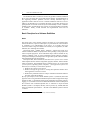
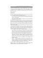
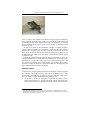
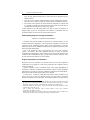
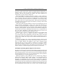
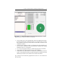
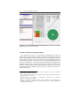
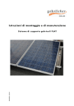
Towards A Software Museum: Challenges and
Opportunities
Ernst Denert
Klaus-Peter Löhr
sd&m AG
Thomas-Dehler-Str. 27
81737 München
E-mail: [email protected]
Institut für Informatik
Freie Universität Berlin
Takustr. 9
14195 Berlin
E-mail: [email protected]
&
Introduction
Although the history of automatic computation is quite young, the rapid
development of electronic computers has awoken the interest of the historians,
who fear important facts about early computing might get lost. The most visible
result of the combined efforts of historians and computer veterans are computer
museums which have been founded in several countries and have become quite
popular.
Computer museums belong to the category of science and engineering
museums. Their exhibits tend to do more than just present some fancy machinery:
they try to educate visitors, i.e., convey an understanding of how technical
artifacts work and how they were perfected over generations of engineers. A
prominent example of this kind of museum is the Deutsches Museum in Munich,
one of the world’s most comprehensive science and engineering museums.
Presenting computers in a museum has been done very successfully in the past,
but has focused on only one part of the computing business (actually a small
part)—hardware. The really important part—and one of the key technologies at
the turn of the century and for a long time to come—is software. So why are
software systems not presented in computer museums? The answer seems
obvious: software is immaterial and invisible, so there is nothing to be presented.
Or so we think.
The authors set out to question this dogma. We are convinced that it is possible
to make software an exciting exhibit in a museum - a software museum. Our
opinion was confirmed when we visited the newly created Mathematical Cabinet
in the Deutsches Museum. Here, Friedrich L. Bauer has managed to present the
most elusive subject imaginable, mathematics, to the visitors, or at least to wet
their mathematical appetite by allowing a playful encounter with strange objects1.
It occurred to us that software, too, could be made visible, tangible and playful,
and thus reach people.
1
Friedrich L. Bauer: Mathematisches Kabinett. Deutsches Museum, München 1999
2
Ernst Denert & Klaus-Peter Löhr
The immaterial nature of software is not the only problem a software exhibition
has to solve. The sheer mass of past and existing software, the disappearance of
the supporting hardware platforms and the virtually unlimited range of
applications make it hard to see how a software exhibition could ever cover its
subject in an adequate way. In exploring the issues, we will first develop a few
principles that we consider crucial to any successful attempt to create a software
exhibition. Then, to make things more concrete, we will present three case studies
of “exhibits”. Finally, several technical and organizational issues will be
addressed.
Basic Principles for a Software Exhibition
Goals
The raison d’être of any museum, whatever its theme, is to save characteristic
items from oblivion, to preserve masterpieces, to present them as exhibits and thus
to contribute to an understanding of the history of a specific field. The
educational efforts range from almost non-existent (as in art galleries) to rather
elaborate (as in ethnological museums).
These three facets - exhibits, history, education - what do they mean for a
software exhibition? While everybody knows what a painting is, few people know
what a computer program is. So the educational aspect will be essential for any
software exhibition. Only if people understand general software principles,
concepts and techniques, will they be able to appreciate specific software exhibits
and understand historical developments.
This implies that, first and foremost, there has to be a software basics section
which explains the basic notions of algorithm, program, software, and how all this
relates to hardware. Then different kinds of software have to be covered, both
systems software (operating systems, compilers, ...) and application software. For
each kind, it is necessary to answer three questions:
1. What are the problems to be solved?
2. What are the typical approaches to solving these problems and how have
these approaches evolved over time?
3. What are the prominent historical examples of that kind of software and how
have they solved the problems?
By way of an example, let us consider database systems: 1. (Problems) The ACID
properties2 have to be guaranteed and efficient queries must be supported for large
amounts of data. 2. (Approaches) Some typical techniques are indexing, locking,
logging, etc., and we have seen more refined manifestations of these techniques in
the evolution from indexed-sequential files to relational to object-oriented
database systems. 3. (Examples) We may want to present, say, VSAM, IMS and
Oracle as prominent representatives.—We will revisit database systems in Section
3.3 below.
2
ACID is the acronym for atomicity, consistency, isolation, durability.
Towards A Software Museum: Challenges and Opportunities
3
There is one additional theme a software exhibition has to cover - software
engineering, the very craft of building software systems. Representing the history
of software engineering adequately, with its victories and defeats, may be
impossible to achieve in a museum. We must admit that we have not given it
much thought so far.
Arrangement
As a museum defines itself through its exhibits, we have to answer the question
“What is a software exhibit?” The simplistic answer is:
1. A condensed, educational documentation of the system is presented on wall
charts, including a requirements document, a user’s manual, a design sketch
and some code fragments.
2. The program is actually installed on a computer; it can be run, perhaps even
be used interactively by visitors.
It is obvious that this approach would never work. The possibilities for running
legacy code are very limited. Emulation is rarely supported, and exact simulation
of obsolete hardware (including peripherals!) is an unrealistic task. Moreover,
even if “the real system” were running, would this be helpful to the visitor who
cannot check the code anyway? And even if we could check it, who would go
through the documentation and try to understand what is going on? Not even the
typical computer scientist.
This is not to say that exhibits should not use computers. Actually, the museum
should rely heavily on computers—not for running original software masterpieces
but for running special educational software, mainly for documentation and
visualization purposes. Take the subject of operating systems, for instance. A
section on operating systems would be arranged as follows:
1. An introduction to the purpose of operating systems is given (possibly
drawing on the visitor’s knowledge as a computer user), and the typical jobs
done by an operating system are sketched using a wall chart. In addition,
online access to two or three contemporary operating systems is given.
2. Typical operating-system areas, e.g., file management, are chosen for an indepth study. They are first explained, again using a wall chart, and then
presented on a computer to allow an interactive, playful encounter. The
installed software would simulate a simplified file management system and
visualize its operation, down to the handling of file descriptors, block
buffers and disk I/O.
3. “Famous” operating systems are presented (say, THE, Multics, Unix,
OS/360,...), together with details of the people and organizations involved;
prominent features of the systems are highlighted. Connections to the
visualized functionalities just mentioned are established. - What kind of
media support would be most helpful here remains to be seen.
We aim not only to visualize software, but also to make it tangible. This would be
extremely helpful - in the software basics section mentioned earlier - for
explaining to children (and others!) what software is all about.
4
Ernst Denert & Klaus-Peter Löhr
Software Exhibits: Three Examples
In order to make the software museum concept more concrete, we will pick three
examples of what might be called a software exhibit: the first is concerned with
the very notion of software, the second is a visualization example, and the third is
a real-world system. We hope that this eclectic approach will help the reader to
understand our intentions better.
Coming to Grips with Software
“I hear and I forget, I see and I remember, I do and I understand.”
Chinese proverb
“Software is immaterial: it consists of programs, which are plans for sequences of
actions, to be executed automatically by a computer.” A definition like this does
not really make sense to those who have never written a program. A software
museum has to reach out to ordinary people, not only to the initiated; so visitors
should be led to an understanding of what these immaterial “programs” are all
about.
Material Programs for Playing Music
If a program is an executable plan, then how does a programmer plan the
execution steps, and how can a machine execute those steps? In our view,
grasping the essentials of programming should be facilitated by allowing visitors
to physically grasp programs as well as the executing machines and the
embedding environments the machines interact with. Visitors should even be able
to build and run simple programs by themselves.
A program is, of course, just a piece of information, independent of the
physical representation that may be used for communication among humans (e.g.,
handwriting on paper) or machines (e.g., bits in electronic memory). Still, there
are program representations—for mechanical or electromechanical devices—that
are much more material than either handwriting or electronic bits. This is how we
want the term material programs to be understood: consider, e.g., a music box
that is driven by a program represented as pins on a revolving cylinder, touching
the tuned teeth of a metal comb; or take the classical mechanical loom where the
program is punched into a cardboard tape, or take a hand organ.
Actually, there is a “programmable” toy that resembles a music box: punched
holes on different “stave lines” of a cardboard tape represent notes. The tape is fed
into a mechanical device similar to a music box and “the program is executed” by
turning a crank (see Fig. 1). Prepare your own tape and play your favourite tune.
Towards A Software Museum: Challenges and Opportunities
5
Fig. 1. Primitive music box using cardboard tape
Music is, in fact, a prime example of the abstract concept of program. Admittedly,
these “programs” are rather simple, as there is no memory, no parametrization and
no branching (though simple repetitions do occur). But the steps to be executed
have a well-defined meaning and a piece can be executed by both humans and
automatic devices.
We plan to use music as the introductory analogue to computer programs.
Visitors (especially children) are encouraged to punch their favourite songs (or
those that are presented by the museum) into tapes and feed them into music
boxes. There will be both mechanical and electromechanical boxes, and there will
be traditional boxes with fixed (or removable) cylinders. Barrel organs should be
on display as well3.
It should be emphasized that the particular designs of the different devices are
less important than the fact that the differences between them do not really matter.
“Greensleeves” is independent of how its notes are represented and played—and
you can have an automaton play it (if this satisfies your demands). The hands-on
experience of different devices is considered essential for a thorough grasp and
proper understanding of the notion of program.
Grasping Graphics
Computers have memories and peripheral devices. Realistic computer programs
have branches and loops, and they cause effects in memory and in their
environment. To bridge the gap between computers and these simple music
boxes, we suggest a simple electromechanical plotting device:
•= The plotter is controlled by a program on a punched tape4 which is almost
identical in appearance (e.g., has the same number of lines) to the music tape.
Each column contains one command (rather than a chord). Unlike the music
3
4
This part of the exhibition would, of course, be organized jointly with the hardware division.
Remember that early plotters were operated off-line in this way, controlled by a punched tape
that had been produced by a computer.
6
Ernst Denert & Klaus-Peter Löhr
tape, this tape should remain fixed; a control unit moves along the tape (in
both directions)5.
•= There are a few registers, and both integer counters and Boolean switches.
The values of two of these registers correspond to the coordinates of the pen.
•= The content of the registers can also be observed on displays on a panel, and
it is possible to modify the content from the panel. Thus the plotter can be
operated both manually and by means of a program.
A fairly limited set of commands suffices for quite a variety of programs. A
sample design is given in the appendix. The number of commands does not
exceed the number of stave lines we used for the music box.
Understanding Programs Through Visualization
“Software is invisible and unvisualizable.”6
No matter what specific exhibits are chosen for a software museum, we will
encounter all kinds of algorithms, concrete programs, fragments of systems and
complete systems. Exhibiting software items—in any representation—will only
make sense if visitors are enabled to understand their important properties, both
static (structural) and dynamic.
This is not possible by mere code inspection. In recent years, however,
software visualization7 has made significant advances in terms of program
comprehension and debugging. There will be more progress in this direction, and
we believe that visualization can play a pivotal role in a software museum. After
all, any museum relies heavily on visual exhibits.
Program Visualization and Animation
Programs want to be executed. It is obvious that not even the most ingenious
visualization of a program (as a static item) could allow us to dispense with an
animated execution.
Program animation comes in different forms, from simple highlighting of
statements to elaborate visualization of the dynamic effects on data, peripherals
and networks8. We will use a mixture of different techniques as described below.
Both code and data animation techniques will be applied.
In many cases, a software exhibit may lend itself to being modelled as an
abstract data object (such as a Modula module). The object has a procedural
interface comprising several operations. The available operations are presented in
5
6
7
8
Instead of a punched tape, a metal rod with adjustable pins would be preferable, where each
pin can be in one of the two positions Up/Down. This would make it extremely easy to build
and modify a program “by hand”, without the hassle of punching (or sealing) holes.
Frederick P. Brooks: No silver bullet – essence and accidents of software engineering. IEEE
Computer 20.4, April 1987, 10-19
John T. Stasko, John Domingue, Marc H. Brown, Blaine A. Price (eds.): Software
Visualization. The MIT Press 1998
Note that we talk about program animation here. Algorithm animation works on a higher level
of abstraction, possibly not even showing code but only an animated model.
Towards A Software Museum: Challenges and Opportunities
7
an interface window on the screen. Visitors can trigger operations interactively, in
arbitrary sequence. Or they can construct a program in advance, using the given
operations, and then step through the program. The chosen operations are
composed in a program window in either case.
Browsing through the software behind the interface is made possible by
hypertext functionality: a call statement can be expanded (recursively) by clicking
on it, causing the code of the operation to be displayed in a separate program
window. The data structures involved are visualized in a data window, using
boxes, tables and arrows (representing pointers). With object-oriented designs,
encapsulated objects would first appear as blank boxes; clicking on them would
reveal their inner structure.
Both code and data should be animated. As the user steps through the code, the
current statement is highlighted. A chosen “step” can be the evaluation of a
condition, an elementary statement (assignment or operation call) or a complete
loop. For expanded operation calls, the system will step through the individual
statements of the operations. The data structures are animated by changing box
contents and arrows and by visualizing how data moves (i.e., is copied) from one
box to the other. Depending on the specific exhibit, data flow between the
program and the environment could be visualized as well.
Remember that to specify or understand the behaviour of an abstract data
object we usually refer to an abstract model that is independent of the
representation chosen by the implementer. Note that what is shown in the data
window cannot clearly be classified as either a model or representation: it is more
concrete than a model, but it may be more abstract than data declarations in
program code.
Speaking of program code—which programming language should be used
here? The answer depends on the nature of the exhibit. Of course, if we have a
piece of original software, the language is given. But to illustrate typical
techniques that occur in many systems, we should use an extremely readable
(albeit formal) language, designed for the very purpose of explanation. An indepth discussion of language issues is beyond the scope of this paper; the reader
will get a glimpse of a typical language in the example in the next section.
An Example: Operating System Support for File Access
We tested our ideas using an example from the domain of operating systems: the
exhibit File Access should convey to the visitor an understanding of an important
piece of systems software. A file system can be viewed as an abstract data object
exporting operations such as open, read, etc. The functionality of these operations
is quite straightforward—but the implementation is not.
Hands-on experience of the exhibit File Access would start by opening a
window that presents the interface shown in Fig. 2. A kind of mixfix syntax is
used here. For example, READ FROM RETURN is an operation name; the
parameters are interspersed with parts of this name, FROM merely enhancing
readability and RETURN having the obvious special meaning: it separates byvalue parameters from by-result parameters. Parameter types are given below the
parameter names. Possible exceptions are not indicated in the specification, so as
to avoid information overload. They can, of course, occur at runtime (example:
8
Ernst Denert & Klaus-Peter Löhr
reading from a closed stream), aborting the execution and producing an error
message.
INTERFACE FileAccess
{Allows reading/writing from/to text files.
A text file is identified using a file name.
Opening a file creates a stream through which
characters can be read/written sequentially.}
OPEN filename RETURN streamhandle
(Text)
(Pointer to Stream)
{Creates stream between program and file.}
CLOSE streamhandle
(Pointer to Stream)
{Discards a stream.}
READ howmany FROM streamhandle RETURN data
(Number)
(Pointer to Stream) (Text)
{Reads specified number of characters from stream
to data.}
WRITE howmany data TO streamhandle
(Number) (Text) (Pointer to Stream)
{Writes specified number of characters from data
to stream.}
SEEK position IN streamhandle
(Number)
(Pointer to Stream)
{Adjust stream to continue reading/writing at
given position in file.}
Fig. 2. File system specification
Clicking on an operation is done in either of two modes: interactive or noninteractive. In the former case, the operation is executed immediately. In the
latter, the operation is appended to the program under construction. In both cases,
the user is prompted to give the actual parameters first; the operation call is then
added to the program window. Variables are introduced on the fly9.
The relevant data structures for File Access are streams, file descriptors and
block buffers. They can be visualized as shown in Fig. 3; this is a screen shot from
a visualization program that simulates a flat file system using conventional
syntax10. There are four standard windows:
9
10
There are a few additional statements for assignments, conditionals and loops.
Stefan Freyer: Visualisierung von Dateisystem-Mechanismen. Diplomarbeit, FB Mathematik
und Informatik, Freie Universität Berlin, April 2000
Towards A Software Museum: Challenges and Opportunities
9
Fig. 3. Startup view of windows for File Access visualization
•=
•=
•=
•=
•=
Control allows users to step through their program (in different-sized steps,
forwards and backwards, at different speeds). To avoid information overload,
ticks indicate the files (up to four) whose relevant data are shown in the
visualization window.
Commands is the interface window; it contains the file system interface. The
user can choose commands, insert actual parameters and place the resulting
statements in the user code window.
User code is the program window; it contains the program to be executed.
Output displays any output produced by the println command.
Visualization is the data window; it contains the visualized data of the file
system. As the program is being executed, the data flow is animated: text and
numbers fly across the screen, and arrows are drawn and redrawn.
Fig. 4 shows the screen after the program shown in the User code window has
been executed.
10
Ernst Denert & Klaus-Peter Löhr
Fig. 4. Snapshot of File Access visualization
Towards a Toolkit for Program Animation
The exhibit File Access is a one-of-a-kind, hand-crafted item. Now the
museum will certainly display a multitude of exhibits, from different kinds of both
systems and applications software. We may want to provide insight into many of
these programs, so there is an obvious need for tools that support the animated
visualization of programs. Several such tools exist, but program animation is still
an active research subject11. We do not know of any system that would support the
animation sketched above. Existing systems tend to address the design12 and
analysis13 of large systems; they are meant to support the expert and try to abstract
from details. The level of detail we need is found, e.g., in the VCC system for C
program animation14.
11
John T. Stasko, John Domingue, Marc H. Brown, Blaine A. Price (eds.): Software
Visualization. The MIT Press 1998
12
John J. Shilling, John T. Stasko: Using animation to design object-oriented systems. ObjectOriented Systems 1, 1994, 5-19
13
Wim De Pauw et al.: Jinsight – Visualizing the Execution of Java Programs.
http://www.research.ibm.com/jinsight
14
Ricardo A. Baeza-Yates, Gastón Quezada, Gastón Valmadre : Visual debugging and
automatic animation of C programs. In P. Eades, K. Zhang (eds.): Software Visualization.
World Scientific 1996, 46-58
Towards A Software Museum: Challenges and Opportunities
11
VCC also suggests the ideal solution—a tool that would automatically generate
an animated exhibit, given a certain program module. While aiming at complete
automation seems unrealistic, there is a fair chance of finding a semi-automatic
solution. The static visualization part will not be too hard. But attractive
animation will require some non-trivial manual intervention.
Semi-automatic generation of animated programs should certainly not be
confined to one specific programming language. We should have a generic tool
that comes in three parts: a front end that would compile the program into an
intermediate-language version; a middle part that would generate a “vanilla”
visualization and animation; and a back end that would allow the curator to
produce a polished version interactively.
Lufthansa’s Reservation System
As a third example of an exhibit, we would like to present an application that is
very vivid and interesting from a user point of view and very fruitful from a
technical point of view – seat reservation.
It is only for the last 30 years that Lufthansa (LH) flights have been booked
using an electronic reservation system (ERS). Before that, booking was done in a
huge hall at Frankfurt Airport, with boards mounted to the walls showing the
individual flights, e.g., LH 400 Frankfurt-New York, with a space for each day on
which they operated, for a period of several months in advance. Employees were
in charge of processing all reservation requests, which they received via
telephone, via telex or in writing. By attaching a pincard containing the
passenger’s reservation data to the board, an employee visualized the reservation
and ensured that no seat was assigned twice. The hall was so big that binoculars
were used for checking the boards for vacant seats on a specific flight.
In addition to this central reservation hall, there were offices in about six cities
where, in a similar way, a certain contingent of flights could be booked which
were assigned to these offices by the headquarters. The city offices communicated
with the Frankfurt headquarters via telephone or telex.
Thus, the essential tools of this booking procedure were boards, notes, record
cards and card file boxes, telephone and telex. Most importantly, a huge number
of employees were needed in spite of the relatively small volume of air traffic.
Today, Lufthansa’s bookings could not be handled this way: not only would the
old system fail to meet passengers’ demands for fast response—it would actually
be infeasible. In short, Lufthansa would not be able to maintain its flight
operations; scheduled air traffic would be impossible.
In order to solve this problem, Lufthansa introduced an ERS in the late 1960s
and early 1970s. With the ERS, reservations are processed in a central database.
This database is integrated into a worldwide network, which can now be accessed
not only by Lufthansa employees but by everyone, using the Internet-based
World-Wide Web. Moreover, it is connected to a network of reservation systems
shared with many other airlines (the SITA network) so that their flights can be
booked directly as well.
The exhibition intends to present this example of application software by
contrasting the former manual procedure with today’s electronic reservation
system. Of course, the central hall cannot be rebuilt in its original size, but it
12
Ernst Denert & Klaus-Peter Löhr
could be presented in the form of a diorama. The main aim is to show the former
tools as faithfully as possible. Visitors will then be able to see how costly, slow
and error-prone the manual procedure was.
The diorama will be contrasted with the fundamental workings of an ERS. This
will allow important software aspects to be demonstrated, for instance
•= What a complex application is—and the fact that an ERS is even linked to
other applications, including the ticketing and the check-in systems
•= How worldwide access to a central application is made possible, i.e., how
Lufthansa’s employees, travel agents and, ultimately, everybody can book
flights through the ERS
•= How such a system must be operated so that it works reliably around the
clock
•= What a database accomplishes (being the core component of the ERS)
•= How data access is synchronized so that a seat on a flight is actually given to
only one passenger
It would be a special attraction if the visitors were able to access the real
Lufthansa system from within the museum. This might even be realized: taking
stock of Lufthansa’s old booking procedure has been the subject of a recent
Master’s thesis15; Lufthansa’s archives were searched and witnesses of that period
were interviewed.
Technical and Organizational Issues
As mentioned earlier, a software exhibition cannot possibly be conceived
independently of a computer exhibition. Explaining what a program is will
invariably be tied up with explaining the functionality of computer hardware. It
remains to be explored how the “hardware” presented in Section 3.1 can be
related to the real hardware found in the computer exhibition.
It is obvious that extensive computer support—hardware and “metasoftware”— will be indispensable for the documentation, visualization and
maintenance of software exhibits. Given the shortage of resources museums
commonly face, free software and cheap hardware must be used wherever
possible. A network of PCs running Linux would certainly represent an adequate
infrastructure. Large-format screens and electronic whiteboards might be
desirable for some exhibits (and may become less expensive in the future). As
regards hardware items, we hope to find industrial sponsors who are interested in
supporting an undertaking as foolhardy as a software exhibition!
The main effort will, of course, be procuring, adapting and developing the
meta-software mentioned above. This would strain the resources of even the
wealthiest museum. We expect, however, to find enough enthusiasts in the
computer science community to help develop software and prepare specific
exhibits.
15
J.A. Haidn: Hardware und Software: Computertechnik im Einsatz in den 1960er und 70er
Jahren. Magisterarbeit, Historisches Seminar, Ludwig-Maximilians-Universität München,
März 2000
Towards A Software Museum: Challenges and Opportunities
13
Still, a software exhibition may experience funding problems in the long run.
Unlike other exhibitions of, say, cars, machines, household items etc.,
maintenance does not just involve dusting (or repairing or procuring of an item
once in a while). Even if the exhibits do not change, the infrastructure has to be
maintained and will require permanent renewal, merely because of the fast pace of
hardware development. In this respect, the museum’s situation is no different
from that of any other computer user.
The complexity of the task of establishing a software exhibition obviously
requires a sizeable team of computer scientists, science historians and committed
custodians. Such a team does not yet exist. One object of this paper—and not the
least—is to get people to help with this undertaking. Success is not guaranteed, as
the subject certainly resists straightforward treatment. But this very fact makes it
such an exciting endeavour.
Acknowledgements
We enjoyed our discussions with Friedrich Bauer who helped shape many of the
ideas presented here. His enthusiasm for the vision of a software exhibition
confirmed our hope that the idea might not be too bizarre after all. Stefan Freyer
contributed to the file access example by practically exploring the required
animation techniques in his Master’s thesis. Thanks also to Christian Zick for
providing the picture of the music machine.
14
Ernst Denert & Klaus-Peter Löhr
Appendix: Design of a Simple Plotter
1. There are 8 registers - 4 integer counters and 4 Boolean switches:
counters
C1
C2
C3
C4
= x position of pen
= y position of pen
switches
S1
S2
S3
S4
= pen up/down
= colour black/red
2. There are 6 elementary commands:
inc
dec
clr
init
on
off
increments given counter(s) by 1
decrements given counter(s) by 1
sets given counters to 0
resets given counters to their initial values
turns given switches on
turns given switches off
3. There are 8 control commands:
if
ifno
ifeq
ifls
if 0
evaluates logical OR of given switches;
if true, proceeds with next command,
else continues after next matching cont or retn (whatever is next)
evaluates logical OR of given switches;
if false, proceeds with next command,
else continues after next matching cont or retn (whatever is next)
checks for equality of given counters, then proceeds like if
checks Ci < Ck (i<k) for given counters, then proceeds like if
checks given counters for 0, then proceeds like if
cont continues with next command (i.e., no-op)
retn returns to last if command
exit continues after next retn (or else stops program)
4. Note that the if command (and its variants) works both as the traditional if
and as a while, depending on whether the matching command is cont or
retn. Also note that the control commands are designed as nearly as possible to
control syntax. Executing a control command requires scanning the program; the
Towards A Software Museum: Challenges and Opportunities
15
benefit is that jump instructions and the ensuing notion of “label” or “address”
are avoided16. The nesting of control structures, however, is very limited.
5. The program tape has 18 lines, one line for each command and four lines to
specify the counter or switch numbers 1-4. The possible commands could, of
course, be encoded in a more compact fashion, but only at the price of worsening
the look-and-feel.
6. A possible layout of the panel is shown in Fig. 5. At any point in time, the
values of the counters and switches are shown in the displays. The elementary
commands can be executed by hand, by pushing the appropriate buttons. Initial
values for a program can be entered in this way.
7. The above design allows for many variations and may not yet be optimal for
our purposes. Some experimental programming should lead to a good
compromise between expressive power, complexity and ease of use - the latter
certainly being the overriding concern.
16
It is open to debate whether or not the machine presented here is a stored-program computer.
In any case, the program store is different from the data store.
16
Ernst Denert & Klaus-Peter Löhr