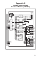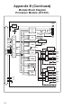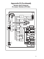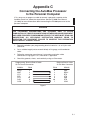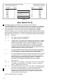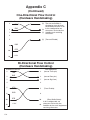
1
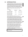
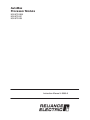
AutoMax
Processor Module
M/N 57C430A
M/N 57C431
M/N 57C435
Instruction Manual JĆ3650Ć6
The information in this user's manual is subject to change without notice.
WARNING
ONLY QUALIFIED PERSONNEL FAMILIAR WITH THE CONSTRUCTION AND
OPERATION OF THE CONTROLLED EQUIPMENT SHOULD INSTALL, ADJUST,
OPERATE, OR SERVICE THIS EQUIPMENT. READ AND UNDERSTAND THIS
MANUAL AND OTHER MANUALS APPLICABLE TO YOUR INSTALLATION.
FAILURE TO OBSERVE THIS PRECAUTION COULD RESULT IN BODILY INJURY.
WARNING
INSERTING OR REMOVING THIS MODULE OR ITS CONNECTING CABLES MAY
RESULT IN UNEXPECTED MACHINE MOTION. POWER TO THE MACHINE
SHOULD BE TURNED OFF BEFORE INSERTING OR REMOVING THE MODULE
OR ITS CONNECTING CABLES. FAILURE TO OBSERVE THESE PRECAUTIONS
COULD RESULT IN BODILY INJURY.
CAUTION: This module contains staticĆsensitive components. Careless handling can
cause severe damage. Do not touch the connectors on the back of the module. When
not in use, the module should be stored in an antiĆstatic bag. The plastic cover should
not be removed. Failure to observe this precaution could result in damage to or
destruction of equipment.
Motorolat 68010 and 68020 are trademarks of Motorola, Inc.
AĆBt is a trademark of AllenĆBradley Corporation.
IBMt is a trademark of International Business Machines, Inc.
Modbust is a trademark of Gould, Inc.
Multibust is a trademark of Intel Corporation.
Reliancer and AutoMaxr are registered trademarks of Reliance Electric Company
ąor its subsidiaries.
E Copyright Reliance Electric Industrial Company 1996.
Table of Contents
1.0
Introduction . . . . . . . . . . . . . . . . . . . . . . . . . . . . . . . . . . . . . . . . . . . . . . .
1.1 Additional Information . . . . . . . . . . . . . . . . . . . . . . . . . . . . . . . . . . . .
1.2 Related Hardware and Software . . . . . . . . . . . . . . . . . . . . . . . . . . .
1.3 Compatibility with Earlier Versions . . . . . . . . . . . . . . . . . . . . . . . . .
2.0
Mechanical/Electrical Description . . . . . . . . . . . . . . . . . . . . . . . . . . . 2Ć1
2.1 Mechanical Description . . . . . . . . . . . . . . . . . . . . . . . . . . . . . . . . . . . 2Ć1
2.2 Electrical Description . . . . . . . . . . . . . . . . . . . . . . . . . . . . . . . . . . . . . 2Ć3
3.0
Installation . . . . . . . . . . . . . . . . . . . . . . . . . . . . . . . . . . . . . . . . . . . . . . . .
3.1 Wiring . . . . . . . . . . . . . . . . . . . . . . . . . . . . . . . . . . . . . . . . . . . . . . . . . .
3.2 Initial Installation . . . . . . . . . . . . . . . . . . . . . . . . . . . . . . . . . . . . . . . . .
3.3 Module Replacement . . . . . . . . . . . . . . . . . . . . . . . . . . . . . . . . . . . . .
3.4 OnĆBoard Battery Replacement . . . . . . . . . . . . . . . . . . . . . . . . . . . .
3.5 Processor Module Diagnostics . . . . . . . . . . . . . . . . . . . . . . . . . . . .
3.5.1 PowerĆUp Diagnostics . . . . . . . . . . . . . . . . . . . . . . . . . . . . . .
3.5.2 RunĆTime Diagnostics . . . . . . . . . . . . . . . . . . . . . . . . . . . . . .
3Ć1
3Ć1
3Ć1
3Ć3
3Ć4
3Ć5
3Ć5
3Ć5
4.0
Programming . . . . . . . . . . . . . . . . . . . . . . . . . . . . . . . . . . . . . . . . . . . . . .
4.1 Loading the Operating System . . . . . . . . . . . . . . . . . . . . . . . . . . . .
4.2 Accessing Processor Ports . . . . . . . . . . . . . . . . . . . . . . . . . . . . . . . .
4.3 Programmable Tick Rate . . . . . . . . . . . . . . . . . . . . . . . . . . . . . . . . .
4.4 Restrictions . . . . . . . . . . . . . . . . . . . . . . . . . . . . . . . . . . . . . . . . . . . . .
4.4.1 Number of Processors in a Rack . . . . . . . . . . . . . . . . . . . . .
4.4.2 Rack Slot Restrictions . . . . . . . . . . . . . . . . . . . . . . . . . . . . . .
4.4.3 Use with the DCS5000 M/N 57C407 Processor Module
or the 57C430 Processor Module . . . . . . . . . . . . . . . . . . . .
4.4.4 Ethernet Commands . . . . . . . . . . . . . . . . . . . . . . . . . . . . . . .
4Ć1
4Ć1
4Ć3
4Ć4
4Ć5
4Ć5
4Ć5
Diagnostics and Troubleshooting . . . . . . . . . . . . . . . . . . . . . . . . . . . .
5.1 The OK" LED Is Off . . . . . . . . . . . . . . . . . . . . . . . . . . . . . . . . . . . . . .
5.2 The BAT. OK" LED Is Off . . . . . . . . . . . . . . . . . . . . . . . . . . . . . . . . .
5.3 BUS ERROR . . . . . . . . . . . . . . . . . . . . . . . . . . . . . . . . . . . . . . . . . . . .
5.4 Common Memory Module Diagnostic Failure . . . . . . . . . . . . . . . .
5.5 Incorrect Data . . . . . . . . . . . . . . . . . . . . . . . . . . . . . . . . . . . . . . . . . . .
5Ć1
5Ć1
5Ć2
5Ć3
5Ć6
5Ć7
5.0
1Ć1
1Ć2
1Ć2
1Ć3
4Ć5
4Ć5
I
Appendices
Appendix A
Technical Specifications . . . . . . . . . . . . . . . . . . . . . . . . . . . . . . . . . . . . . . AĆ1
Appendix B
Module Block Diagram . . . . . . . . . . . . . . . . . . . . . . . . . . . . . . . . . . . . . . BĆ1
Appendix C
Connecting the AutoMax Processor to the Personal Computer . . . . CĆ1
Appendix D
Diagnostic LED Error Codes . . . . . . . . . . . . . . . . . . . . . . . . . . . . . . . . . . DĆ1
Appendix E
Run Time LED Error Codes . . . . . . . . . . . . . . . . . . . . . . . . . . . . . . . . . . . EĆ1
Appendix F
Using Modems with AutoMax Systems . . . . . . . . . . . . . . . . . . . . . . . . . FĆ1
II
List of Figures
Figure 2.1
Figure 2.2
Ć Processor Module Faceplate . . . . . . . . . . . . . . . . . . . . . . . . . . . 2Ć2
Ć Typical RSĆ232C Circuit . . . . . . . . . . . . . . . . . . . . . . . . . . . . . . . . 2Ć3
Figure 3.1
Ć Rack Slot Numbers . . . . . . . . . . . . . . . . . . . . . . . . . . . . . . . . . . . 3Ć2
Figure 4.1
Ć Specifying the SETUP Parameter in an OPEN Statement . . . 4Ć4
III
afadfdfdasfdsfdsdsdfdsfdsfdsfsdfdsa
fdfdsfdsfdfdsfdsfsadfda
sfdfaddfdd
1.0 INTRODUCTION
The products described in this instruction manual are manufactured
by Reliance Electric Industrial Company. The Automax Processor
module plugs into the backplane of an AutoMax rack and executes
application programs which in turn control other AutoMax modules in
the system. The M/N 57C430A and 57C431 Processor modules are
based on the Motorola 68010 16Ćbit microprocessor. The M/N
57C435 Processor module is based on the Motorola 68020 32Ćbit
microprocessor. All three Processors are programmed using three
highĆlevel application languages: BASIC, Control Block and Ladder
Logic.
The Processor modules have the following memory/speed
configurations:
Model
CPU Speed
Memory
M/N 57C430A AutoMax
6010 Processor module
8 mHz
256K Parity RAM
M/N 57C431 AutoMax
6011 Processor module
8 mHz
512K Parity RAM
M/N 57C435 AutoMax
7010 Processor module
25 mHz
512K Parity RAM
Up to four AutoMax Processor modules can be used in a rack
(M/N 57C331, M/N 57C332 or M/N 57C334) to increase the
processing capability and the total memory available for application
tasks. M/N 57C430A, 57C431, and 57C435 Processors can be used
in the same rack. M/N 57C430A Processors make 135KĆ150K
available for application programs depending on which operating
system is loaded onto the Processor. M/N 57C431 and 57C435
Processors make 300K available for application programs, regardless
of which operating system is loaded onto the Processor. Multiple
Processors in a rack require the use of the Common Memory module
(M/N 57C413 or M/N 57C423) for bus arbitration and sharing of
systemĆwide information. The Common Memory module can also be
used with a single Processor module to make available an additional
128K bytes of memory for common, i.e., systemĆwide, variables.
An onĆboard lithium battery and a superĆcapacitor protect the
Processor module from power failures. Should the system lose
power, the onĆboard battery of the M/N 57C430A or 57C431
Processor can maintain the contents of RAM for a minimum of 42
days. The onboard battery of the M/N 57C435 Processor can
maintain the contents of RAM for a minimum of 186 days.
The remainder of this manual describes the functions and
specifications of the module. It also includes a detailed overview of
installation and servicing procedures.
The thick black bar shown at the rightĆhand margin of this page
will be used throughout this instruction manual to signify new or
revised text or figures.
1Ć1
1.1
Additional Information
You should be familiar with the following related publications to use
the AutoMax Processor correctly:
D JĆ3616Ć1 Kermit Communications Software Instruction Manual
D JĆ3618
Norton Editor Instruction Manual
D JĆ3636
Common Memory Module Instruction Manual
D JĆ3649
AutoMax Configuration Task Manual
D JĆ3675
AutoMax Enhanced Basic Language Instruction Manual
D JĆ3676
AutoMax Control Block Language Instruction Manual
D JĆ3677
AutoMax Ladder Logic Language Instruction Manual
D J2Ć3093 AutoMax Enhanced Ladder Editor
D J2Ć3094 AutoMax Enhanced Ladder Language Reference
D Your ReSource AutoMax Executive Software Loading Instructions
D Your ReSource AutoMax Programming Executive Instruction
Manual
D IEEE 518 Guide for The Installation of Electrical Equipment to
Minimize Electrical Noise Inputs to Controllers
D Your personal computer and DOS operating system manual(s).
D Other instruction manuals applicable to your hardware
configuration
1.2
Related Hardware and Software
M/N 57C430A contains one 256K AutoMax Processor module.
M/N 57C431 contains one 512K AutoMax Processor module.
M/N 57C435 contains one 512K AutoMax Processor module. The
Processor module is used with the following hardware and software,
which can be purchased separately:
1. IBMĆcompatible personal computer running DOS V3.1 or later.
2. ReSource AutoMax Programming Executive software (various
model numbers).
3. M/N 61C127 RSĆ232C ReSource Interface Cable. This cable is
used to connect the personal computer to the Processor module.
If you wish, you may also build your own cable using the pin
description found in Appendix C.
4. M/N 57C413B, 57C423 Common Memory module. This module
is used when there is more than one Processor in the rack.
5. RSĆ232C cable used for communicating with other devices
through the Processor ports in the rack not reserved for
connection to the personal computer. If you intend to use these
ports, you will need to build your own cable using the pin
description found in Appendix C.
6. M/N 57C331, 57C332 or 57C334 AutoMax PanelĆMount Rack.
7. M/N 57C491, M/N 57C493, or M/N 57C494 AutoMax Power
Supply Module.
1Ć2
8. M/N 57C385 AutoMax Replacement Battery. Note that the
Processor module comes equipped with one (1) battery.
9. M/N 57C404A Network Communications module. This module is
used to connect racks together as a network and supports
communication with all racks on the network that contain
57C404A modules through a single Processor module. M/N
57C404 can be used to connect racks on a network; however,
you cannot communicate over the network to the racks that
contain M/N 57C404 Network modules. You must instead
connect directly to the Processors in these racks.
1.3
Compatibility with Earlier Versions
AutoMax Processor module M/N 57C430A, M/N 57C431, and
M/N 57C435 are not compatible with Version 1.0 of the AutoMax
Programming Executive software (M/N 57C304Ć57C307).
Processor module M/N 57C430A and M/N 57C431 require Version
2.0 or later of the AutoMax Programming Executive software.
M/N 57C435 requires Version 3.1 or later of the AutoMax
Programming Executive software. M/N 57C430 cannot coĆexist in the
same rack with M/N 57C430A, 57C431, or 57C435.
AutoMax Programming
Executive Software
Version 1.0
M/N 57C304, 57C305
M/N 57C306, 57C307 (updates)
Version 2.0
M/N 57C390, 57C391
M/N 57C392, 57C393 (updates)
Version 2.1D
M/N 57C391
M/N 57C393 (update)
Version 3.0
M/N 57C395
M/N 57C397 (update)
Version 3.1
M/N 57C395
M/N 57C397 (update)
Version 3.3 and later*
M/N 57C395
M/N 57C397 (update)
Compatible
Processor Module
M/N 57C430
M/N 57C430
M/N 57C430A
M/N 57C430A
M/N 57C430A
M/N 57C431
M/N 57C435
M/N 57C430A
M/N 57C431
M/N 57C435
M/N 57C430A
M/N 57C430A
M/N 57C430A
M/N 57C431
M/N 57C435
M/N 57C430A
M/N 57C431
M/N 57C435
M/N 57C430A
M/N 57C431
M/N 57C435
M/N 57C430A
M/N 57C431
*Note that if you are using the AutoMax Programming Executive for
drive control applications, the Universal Drive Controller module
(B/M 57552) is supported only in Version 3.3 and later of the
Programming Executive software.
1Ć3
afadfdfdasfdsfdsdsdfdsfdsfdsfsdfdsa
fdfdsfdsfdfdsfdsfsadfda
sfdfaddfdd
2.0 MECHANICAL/ELECTRICAL
DESCRIPTION
The following is a description of the faceplate LEDs, field termination
connectors, and electrical characteristics of the field connections.
2.1
Mechanical Description
The Processor module is a printed circuit board assembly that plugs
into the backplane of the DCS 5000/AutoMax rack. It consists of the
printed circuit board, a faceplate, and a protective enclosure. The
faceplate contains tabs at the top and bottom to simplify removing
the module from the rack. On the back of the module are two edge
connectors that connect to the system backplane. Module
dimensions are listed in Appendix A.
The faceplate of the Processor module contains two
independentlyĆisolated 25Ćpin D" shell connectors for RSĆ232C serial
I/O links. The upper port (labeled PROGRAMMER/PORT B") of the
leftmost Processor in the rack is reserved for connection to the
personal computer only. The personal computer can communicate
with all Processors in the rack through this connection.
All remaining Processor module ports (both those labeled
PROGRAMMER/PORT B" and PORT A") are available for use by
application tasks running on the respective Processors. Refer to
figure 2.1 for the Processor module faceplate and Appendix C for a
pin description.
2Ć1
AutoMax
6010 Processor
57C430A
BAT.OK
AutoMax
6011 Processor
57C431
AutoMax
7010 Processor
57C435
BAT.OK
1ST
BAT.OK
1ST
OK
2ND
2ND
PORT A PROGRAMMER / PORT B
PORT A PROGRAMMER / PORT B
2ND
OK
M/N 57C430A
6010 Processor
256K
M/N 57C431
6011 Processor
512K
PORT A PROGRAMMER / PORT B
OK
1ST
M/N 57C435
7010 Processor
512K
Figure 2.1 Ć Processor Module Faceplate
2Ć2
The faceplate contains two green status lights and two
sevenĆsegment LEDs used for diagnostic purposes. The upper status
light, labeled BAT. OK", indicates whether the onĆboard battery is
providing sufficient voltage to retain the contents of RAM (ON) or
should be replaced (OFF). See 3.4 for directions on replacing the
battery and Appendix A for battery specifications. The lower status
light, labeled OK", indicates whether the board is operational (ON)
or should be replaced (OFF).
Five preĆassigned variables are available for use in all application
tasks to test the status of the onĆboard battery. These common
boolean variables will have the value 1 if the battery is functional and
0 if the battery is not functional. The variables are named according
to the Processor whose battery is being tested. BATTERYSTATUS0@
is used for the Processor in slot 0. BATTERYSTATUS1@ is used for
the Processor in slot 1, etc. up to slot 4.
See 3.5.1 and 3.5.2 for more information about the two
sevenĆsegment LEDs on the Processor.
2.2
Electrical Description
The Processor module contains a local watchdog timer which must
be reset within a specified interval or the Processor will shut down
and all I/O modules will be reset (initialized to 0, FALSE, or OFF).
Byte parity is supported for all backplane address and data lines.
The superĆcapacitor on the Processor module can be charged to
more than 90% of its rated capacity in approximately 15 minutes and
is typically capable of retaining the contents of RAM memory for
approximately 10 hours should the BAT. OK" light go out and power
is removed from the Processor.
The Processor serial ports support full modem control. RSĆ232C
signals have 450V isolation to logic common. Refer to figure 2.1 for a
typical circuit diagram.
+5V
1
2
XMIT
OPTO ISOLATOR
GND
1
2
+5V
OPTO ISOLATOR
RECV
GND
Figure 2.2 Ć Typical RSĆ232C Circuit
Refer to 4.2 for more information on the characteristics of the
Processor ports available to the user through application tasks.
2Ć3
afadfdfdasfdsfdsdsdfdsfdsfdsfsdfdsa
fdfdsfdsfdfdsfdsfsadfda
sfdfaddfdd
3.0 INSTALLATION
This section describes how to install and replace the Processor
module and the onĆboard battery. M/N 57C430A and M/N 57C431
can be installed in the same rack.
DANGER
THE USER IS RESPONSIBLE FOR CONFORMING WITH THE NATIONAL
ELECTRICAL CODE AND ALL OTHER APPLICABLE LOCAL CODES. WIRING
PRACTICES,
GROUNDING,
DISCONNECTS,
AND
OVERĆCURRENT
PROTECTION ARE OF PARTICULAR IMPORTANCE. FAILURE TO OBSERVE
THIS PRECAUTION CAN RESULT IN SERIOUS BODILY INJURY OR LOSS OF
LIFE.
3.1
Wiring
To reduce the possibility of electrical noise interfering with the proper
operation of the control system, exercise care when installing the
wiring from the system to the external devices. For detailed
recommendations refer to IEEE 518.
3.2
Initial Installation
Use the following procedure to install the module:
Step 1.
Turn off power to the system.
Step 2.
If one or both of the RSĆ232C ports on the Processor are
to be used by application tasks for serial communication
with devices other than the personal computer, use
shielded RSĆ232 cables. Cable connectors must be
equipped with EMI/RFIĆshielded cable clamps attached to
the cable shield. The cable shield must be grounded at
one end. The cable length must be in accordance with the
RSĆ232 specification. Be sure to label the connector so
that it can be easily reconnected later should it ever need
to be removed. A pin description can be found in
Appendix C.
Step 3.
Take the module out of its shipping container. Take it out of
the antiĆstatic bag, being careful not to touch the
connectors on the back of the module.
Step 4.
Activate the onĆboard battery. When viewing the Processor
module from the front, you can access the battery through
the opening in the right wall portion of the Processor's
protective enclosure. Activate the battery by taking it out of
its holder and removing the tape that covers it. Replace
the battery in its holder. Make certain that the battery is
facing in the proper direction, i.e., the end marked +" on
the battery is facing the end marked +" on the battery
holder.
Note that the battery will begin to charge the
superĆcapacitor as soon as the battery is replaced in its
holder. For maximum battery life, you should not remove
3Ć1
the tape from the battery unless you intend to turn power
on to the module immediately.
If you are in a programming checkĆout" mode during
which power may be left off for extended periods of time,
you may wish to leave the tape on the battery and use the
superĆcapacitor for backup instead. The superĆcapacitor
will typically provide 10 hours of backup. Using the
superĆcapacitor for this purpose will extend the life of the
battery.
Step 5.
Insert the module into the desired slot in the rack. In a
single Processor configuration, you can insert the
Processor in any slot 0-4. If the rack will contain multiple
Processors, they can only be placed in slots 1-4. In this
configuration, slot 0 is reserved for the Common Memory
module. Refer to figure 3.1.
Typical 16 Slot Rack
16
Typical 10 Slot Rack
P/S
0
1
2
3
10
4
5
6
7
8
9
10 11 12 13 14 15
Figure 3.1 Ć Rack Slot Numbers
3Ć2
Step 6.
Using a screwdriver, attach cable M/N 61C127 (or your
own cable, built according to directions in Appendix C), to
the port labeled PROGRAMMER/PORT B" on the leftmost
Processor. Attach the cable from step #2 above to ports
being used to communicate with other devices.
Step 7.
Turn on power to the system. The module will
automatically execute its powerĆup diagnostics. See 3.5.1
for more information. When diagnostics are complete, the
sevenĆsegment LEDs on the faceplate of the leftmost
Processor module will display LO", reading top to
bottom. Code LO" means that the operating system
needs to be loaded onto the Processors in the rack. See
4.1 for instructions on loading the operating system. The
LEDs on all other Processor modules in the rack should
be blank. The green OK" light on all Processors should
be lit. The BAT. OK" light on all Processors should also be
lit if the tape was removed from the batteries.
Step 8.
Load the operating system using the directions in 4.1.
3.3
Module Replacement
When you replace the Processor module in a singleĆProcessor rack,
you will need to reĆload the operating system and all application
tasks unless the new Processor already has the operating system
loaded on it and the contents of RAM are valid. In this case, you will
need to load the application tasks only.
In a multipleĆProcessor rack, if your replacement Processor does not
already have an operating system and valid RAM, you will have to
reĆload the operating system and all application tasks to all
Processors in the rack. If the new Processor has an operating
system, you need only load the application tasks that you want to run
on that particular Processor.
Use the following procedure to replace a Processor module:
Step 1.
Turn off power to the system. All power to the rack, as well
as all power to the wiring leading to the module, should be
off.
Step 2.
Use a screwdriver to loosen the screws holding the
RSĆ232C connectors to the Processor. Detach the
connectors from the module.
Step 3.
Loosen the screws that hold the module in the rack.
Remove the module from the slot in the rack.
Step 4.
Place the module in the antiĆstatic bag it came in, being
careful not to touch the connectors on the back of the
module. Place the module and the antiĆstatic bag in the
cardboard shipping container.
Step 5.
Take the new module out of the antiĆstatic bag, being
careful not to touch the connectors on the back of the
module.
Step 6.
Activate the battery by taking it out of its holder and
removing the tape that covers it. Replace the battery in its
holder. Make certain that the battery is facing in the proper
direction, i.e., the end marked +" on the battery is facing
the end marked +" on the battery holder.
Step 7.
Insert the module into the correct slot in the rack. Use a
screwdriver to secure the module into the slot.
Step 8.
Attach the RSĆ232C cable connector(s) to the mating half
on the module. Make certain that the connector is the
proper one for this module. Use a screwdriver to secure
the connector to the module.
Step 9.
Turn on power to the system. The module will
automatically execute its powerĆup diagnostics. At the
completion of its diagnostics, the seven segment LEDs on
the faceplate should display LO" if this is the only
Processor module in the rack or the leftmost Processor in
a multiĆProcessor configuration and there is no operating
system on the Processor. The LEDs on all other Processor
modules should be blank. The green OK" light should be
lit, and the BAT. OK" should be lit if the tape was removed
from the battery.
Step 10.
Load the operating system using the directions in 4.1.
3Ć3
3.4
OnĆBoard Battery Replacement
WARNING
THE BATTERY USED WITH THIS DEVICE MAY PRESENT A HAZARD IF
MISTREATED. DO NOT RECHARGE, DISASSEMBLE, HEAT ABOVE 100_C
(212_F), INCINERATE, OR SWALLOW. REPLACE BATTERY WITH RELIANCE
ELECTRIC M/N 57C385 ONLY. DISPOSE OF USED BATTERY PROMPTLY. FAILURE
TO OBSERVE THIS PRECAUTION COULD RESULT IN BODILY
INJURY.
See section 5.2 for a list of the possible reasons that the BAT. OK"
light on the Processor faceplate can shut off. If you need to replace
the battery, the superĆcapacitor will provide a typical 10 hours of
backĆup power between the time the BAT. OK" light goes off and
power is removed from the rack, and the time you insert and activate
the new battery. If you replace the battery within this time limit, you
will not need to reĆload the operating system and application tasks.
Complete battery specifications can be found in Appendix A.
Use the following procedure to replace the battery on the Processor
module.
3Ć4
Step 1.
Turn off power to the system. All power to the rack, as well
as all power to the wiring leading to the module, should be
off.
Step 2.
Use a screwdriver to loosen the screws holding the
connectors to the module. Remove the connectors from
the module.
Step 3.
Loosen the screws that hold the module in the rack.
Remove the module from the slot in the rack, being careful
not to touch the connectors on the back of the module.
Step 4.
Take the old battery out of the holder. Remove the tape
from the new battery and insert it in the holder. Make
certain that the battery is facing the proper direction.
Step 5.
ReĆinsert the module into the correct slot in the rack. Use a
screwdriver to secure the module into the slot.
Step 6.
ReĆattach the connector(s) to the mating half on the
module. Make certain that the connector is the proper one
for this module. Use a screwdriver to secure the connector
to the module.
Step 7.
Turn on power to the rack. The module will automatically
execute its powerĆup diagnostics. The green OK" light
should be lit, and the BAT. OK" should be lit. If this
Processor or any Processor in the rack displays code
LO", you will need to reĆload the operating system. See
4.1 for more information.
3.5
Processor Module Diagnostics
This section describes the Processor module powerĆup and runĆtime
diagnostics.
3.5.1
PowerĆUp Diagnostics
When you first turn on power to the Processor module or cycle
power, it will run diagnostics on the Eprom and RAM memory,
memory management unit, watchdog timer, parity, interrupts, and
SIO.
If more than one Processor is located in the rack, the leftmost
Processor will also run diagnostics on the Common Memory module.
While running diagnostics, which take approximately 5-15 seconds,
the Processor modules in the rack will display the code dd". When a
module has completed its diagnostics, the LED on the faceplate
labeled OK" will be turned on.
Should a malfunction be detected, all Processors in the rack will be
shut down and the status code indicating which diagnostic failed will
remain on the LED display of the Processor at fault. See Appendix D
for a list of powerĆup diagnostic error codes.
After diagnostics are complete, the Processor begins periodically
resetting its watchdog to indicate that it is functioning correctly. In a
multiple Processor configuration, all of the Processors in the rack will
begin resetting the system watchdog located on the Common
Memory module in addition to resetting their own watchdogs. The
Processor module will reset its own watchdog regardless of whether
the operating system is loaded or not.
Should any watchdog be allowed to expire at any time after
powerĆup diagnostics are complete, all Processors in the rack will be
shut down. If application tasks are currently running in the rack, they
will be stopped. The green LED labeled OK" on the faceplate of the
module at fault will be turned off. This Processor will assert a signal
on the backplane to reset (set 0, FALSE, or OFF) all local and remote
I/O modules.
3.5.2
RunĆTime Diagnostics
During runĆtime, i.e., while executing application tasks, the Processor
continuously performs realĆtime checking of byte parity on the RAM.
The memory management unit (MMU) checks for errors such as
writing to locations that are readĆonly. Should any malfunction be
detected, an error code will be displayed on the LEDs and the
Processors in the rack will be either stopped or completely shut
down, depending upon the severity of the error. See Appendix E for
a list of runĆtime error codes.
Serious hardware malfunctions, however, can result in application
tasks that are currently running being stopped, the OK" indicator
being turned off, and the Processor being shut down. Once a
Processor module has shut down, it will not execute any instructions
or respond to commands from the personal computer until it is reset
by cycling power.
3Ć5
afadfdfdasfdsfdsdsdfdsfdsfdsfsdfdsa
fdfdsfdsfdfdsfdsfsadfda
sfdfaddfdd
4.0 PROGRAMMING
For information about programming, see the AutoMax language
instruction manuals and the AutoMax Executive instruction manual
referenced in 1.1.
The remainder of this section describes how to load the operating
system, or runbase, onto the Processor(s) in the rack and how to
access the available Processor ports through application tasks. Note
that you cannot load a Version 1.0 runbase on a 57C430A or M/N
57C431 Processor module. You must load the runbase from the
Version 2.0 or Version 3.0 Programming Executive software. The M/N
57C435 Processor requires the runbase from the Version 3.1 or later
Programming Executive software. You will not be able to load the
operating system using an earlier version of the Programming
Executive software.
4.1
Loading the Operating System
Before you can go onĆline to any rack in the system, the operating
system, or runbase, for the AutoMax Processor module(s) must be
loaded to the local rack from the personal computer on which you
have installed the AutoMax Executive software. The operating
system, which oversees the operation of the CPU and the execution
of application tasks, is provided in three versions: 6010/6011 Ć
Standard, 6010/6011 Ć Ethernet, and 7010 Ć Standard. The 6010/6011
Ć Standard or 6010/6011 Ć Ethernet operating system can be used
with M/N 57C430A or M/N 57C431 Processors. In order to use the
Ethernet functions that allow communication over Ethernet using the
TCP/IP protocol, an Ethernet Network Interface module (M/N
47C440) must be installed in the rack and the Ethernet operating
system must be used. The Ethernet operating system is also required
if any of the following functions are used in BASIC tasks:
READVAR%, WRITEVAR%, FINDVAR!, and CONVERT%. The 7010 Ć
Standard operating system, which supports all of the Ethernet
functions, must be used with the M/N 57C435 Processor.
When you load the operating system to the Processor modules in the
rack, you will be prompted for which operating system you want to
load for the M/N 57C430A and M/N 57C431 Processors. The 7010 Ć
Standard operating system will be loaded onto all M/N 57C435
Processors. Note that if you have loaded the 6010/6011 Ć Standard
operating system and then you use the Ethernet functions in an
application task, the Processor will display error code 4A on its LEDs
when you try to put the task into run.
The 6010/6011 Ć Ethernet operating system will occupy
approximately 121K or RAM, leaving 135K available for application
tasks on the M/N 57C430A Processor. The 6010/6011 Ć Standard
operating system will occupy approximately 106K or RAM, leaving
150K available for application tasks on the M/N 57C430A Processor.
The M/N 57C431 Processor makes 300K available for application
tasks, regardless of which operating system is used. The M/N
57C435 Processor also makes 300K available for application tasks.
The operating system(s) will be loaded at the maximum baud rate
available for the Processors being used. If you are using 6010/6011
and 7010 Processors in the same rack, make sure the leftĆmost
Processor is a 7010 (M/N 57C435) Processor. This will allow the
operating systems to be loaded at 19200 baud. If the leftmost
4Ć1
Processor in the rack is a M/N 57C430A or M/N 57C431, the
operating system(s) will be loaded at 9600 baud. At 9600 baud, it will
require approximately two minutes to load each operating system to
Processors in the rack. Although they are similar, the operating
systems for the 6010/6011 and 7010 Processor are different. If there
are 6010/6011 and 7010 Processors mixed in the same rack, loading
the operating systems will take approximately twice as long as it
would if there were only one type of Processor in the rack.
Follow the directions below to load the operating system(s) for all
Processor modules in the local rack at one time. You can then load
the operating system(s) to all racks on all networks in the system.
Note: If you load an operating system into a Processor(s) that
already contains one, the new operating system will write over
the existing operating system, and any tasks in the Processor(s)
will be deleted.
1. If you have not already done so, turn on the personal computer
and run the AutoMax Executive by typing
AUTOMAX2
or
AUTOMAX3
2. Turn on power to the rack. You will note that the leftmost
Processor module in the rack displays the letters L" and O"
(reading top to bottom). This code prompts you to Load the
Operating system. Because Processor modules have onĆboard
battery backup, you will need to reĆload the operating system
only when enhancements become available, when you change
the password for the rack using the PWOS.EXE utility or when a
Processor module in the rack is replaced.
3. If you have not already done so, connect the personal computer
to the leftmost processor in the rack, following the directions
in 4.4.
4. Enter a <CR> at the initial screen. If you are using AutoMax
Version 2, select F10 for Load Operating System". If you are
using AutoMax Version 3, select Load Operating System" from
the Commands menu. Note that you will see the message Local
OS invalid Ć Direct connection only" before you load the
operating system for the first time. The AutoMax Executive
software will load the operating system onto all Processor
modules in the local rack at the normal baud rate. The AutoMax
Executive will display on the screen the portion (%) of the
operating system that has been loaded.
5. When installation begins, the code L" O" will disappear from the
two sevenĆsegment LEDs on the leftmost Processor module. The
LEDs should be blank. If any error codes appear on the LEDs of
the leftmost Processor, the loading was not successful. Repeat
step 4 above.
6. You can now load the operating system to other racks in the
system connected to the local rack (the rack to which your
personal computer is connected) through 57C404A Network
Communication modules. For any network containing 57C404
Network Communication modules, you must connect directly to
each rack on the network to load the operating system (see steps
1Ć5 above).
4Ć2
All Processors in all racks on a network containing only 57C404A
modules can be accessed and loaded through the single
connection at the local rack. Note that you do not need to
establish a network connection through the ONĆLINE menu to
load an operating system over a network. The loading procedure
is always performed through Load Operating System on the
Commands menu.
To load the operating system over a network(s) connected to the
local rack through 57C404A Network Communication modules,
select Load Operating System" from the Commands menu
again. Select N" to load the operating system over the
network(s). Then select A" to load the standard operating system
or E" to load the Ethernet operating system. At this point, you
have three choices:
4.2
Ć
enter A" to load the operating system to all drops on all
networks that do not already have an operating system.
When the procedure is complete, the system will print the
drop numbers that have not been loaded to the screen.
Ć
enter O" to load the operating system to all drops on all
networks, regardless of whether the Processors in those
drops already have an operating system. This option will
write over all operating systems that exist in all Processors on
all networks. It will also require that you reĆload any tasks that
exist on those Processors. Note that this option requires the
password to be entered.
Ć
enter the slot number of the Network module representing
the network you want to load over. If you select this option,
you will also be able to choose to load the operating system
to one drop, all drops on this network where there is no
operating system, or to load the operating system to all
drops on this network regardless of whether there is an
existing operating system. This third option will require that
you reĆload any tasks that exist on the Processors whose
operating systems were overĆwritten. If you choose the third
option, the system will print the drop numbers that have not
been loaded to the screen. The password is required to
overĆwrite any existing operating system.
Enter your choice and <CR>.
Accessing Processor Ports
All Processor ports in the rack except the port
PROGRAMMER/PORT B" in the leftmost Processor are available to
the user. A port can be accessed using the OPEN statement (OPEN
PORTA or OPEN PORTB) in BASIC tasks running on the specific
Processor on which the port is located. Refer to JĆ3675 for more
information on the OPEN statement.
Refer to figure 4.1 for information about the OPEN statement SETUP
parameter for the AutoMax Processor. Defaults are indicated by (D).
4Ć3
hex number
0
15
14
D
13
12
11
10
0
9
8
7
6
0
5
4
3
2
1
0
OPTIONAL TERMINATION
CHARACTERS FOR INPUT
STATEMENTS
0D00 = Default Setting
1: XĆON, XĆOFF HANDSHAKE
ENABLED (D)
1: HARD COPY DEVICE
0: NON HARD COPY DEVICE (D)
1: ECHO ON (D)
0: ECHO OFF
0: 7ĆBIT CHARACTERS
1: 8ĆBIT CHARACTERS (D)
0: ODD PARITY (D)
1: EVEN PARITY
0: PARITY DISABLED (D)
1: PARITY ENABLED
0: 1 STOP BIT (D)
1: 2 STOP BITS
0: HARDWARE HANDSHAKING
DISABLED (D)
1: HARDWARE HANDSHAKING
ENABLED
Figure 4.1 Ć Specifying the SETUP Parameter in an OPEN Statement
4.3
Programmable Tick Rate
Control Block, BASIC, and PC tasks can be executed at a fixed scan
rate. The scan rate for a Control Block task is set using the
SCAN_LOOP function; the scan rate for a BASIC task is set using the
START EVERY statement; the scan rate for a PC task is set in the
editor. (In addition, a BASIC task can be delayed by using the DELAY
statement.) All of these scan rates can be specified in terms of ticks.
The programmable tick rate" allows you to change the definition of
the tick. By changing the tick, the time base for tasks is changed.
This change allows you to run a task at a scan rate other than the
default of 5.5 msec. It also allows you to execute application tasks at
more easily understood scan times (5.0 msec or 10.0 msec.).
The tick rate is set using the Rack Configurator in the AutoMax
Programming Executive Version 3.1 or later. It is not available when
using previous versions of the Programming Executive. The tick rate
can be set when a Processor module is added or modified. The
programmable tick rate can be set in increments of 0.5 msec.
between 0.5 msec and 10.0 msec. For compatibility, the default tick
rate is 5.5 msec. The tick rate is defined separately for each
Processor in a rack.
The tick rate is transferred when the configuration object code is
transferred to the Processor. The tick rate is set on the Processor
immediately when the configuration is loaded.
4Ć4
A Control Block task containing the CML block must not be present
when a tick rate of other than 5.5 msec. is used. If a Control Block
task with the CML block is installed and the tick rate is not 5.5 msec.,
the task installation will fail.
A tick rate below 2.0 msec is not recommended for 6010/6011
Processors due to system overhead. A Control Block task containing
with at most 15 average blocks (an average block has a 70 msec
execution time) can run with a 2.0 msec. tick rate; a task with 30
blocks can run at 3.0 msec.
4.4
Restrictions
This section describes limitations and restrictions on the use of this
module.
4.4.1
Number of Processors in a Rack
A maximum of four Processor modules may be plugged into the
rack. M/N 57C430A, M/N 57C431, and M/N 57C435 can be used in
the same rack.
4.4.2
Rack Slot Restrictions
A Processor module can occupy any slot from 0Ć4 in the 6, 10 or
16Ćslot AutoMax rack. If the rack will contain multiple Processors, slot
0 must contain a Common Memory module and slots 1Ć4 can contain
Processors.
4.4.3
Use with the DCS5000 M/N 57C407 Processor
Module or the 57C430 Processor Module
A M/N 57C430A, M/N 57C431, or M/N 57C435 Processor module
cannot be used in a rack that also contains a M/N 57C407 Processor
module or a 57C430 Processor module.
A rack can contain either 1) DCS5000 Processors only, or 2)
M/N 57C430A, 57C431, and 57C435 Processors only. You can,
however, connect the racks together over a network.
4.4.4
Ethernet Commands
All tasks using Ethernet commands must be run on the leftĆmost
Processor in the rack.
4Ć5
afadfdfdasfdsfdsdsdfdsfdsfdsfsdfdsa
fdfdsfdsfdfdsfdsfsadfda
sfdfaddfdd
5.0 DIAGNOSTICS AND
TROUBLESHOOTING
This section explains how to troubleshoot the Processor module and
field connections. If the problem cannot be corrected by following the
instructions below, the module is not userĆserviceable.
WARNING
WHEN WRITING TO OUTPUTS, BE CAREFUL TO INSURE THAT NO UNEXPECTED
MACHINE MOTION WILL RESULT. FAILURE TO OBSERVE THIS PRECAUTION
COULD RESULT IN BODILY INJURY OR DAMAGE TO EQUIPMENT.
5.1
The OK" LED Is Off
Problem: The OK" LED on the Processor module faceplate is off.
The possible causes of this problem are the following: the Processor
has failed its powerup diagnostics, the watchdog timer has been
allowed to expire, or the power supply is malfunctioning. If the power
supply is functioning correctly, i.e., providing sufficient power to the
rack, the Processor module must be replaced. Use the following
procedure to isolate a problem with the power supply:
DANGER
THE CONNECTOR ON THE FACEPLATE OF THE POWER SUPPLY IS AT LINE
VOLTAGE WHEN AC POWER IS APPLIED. DISCONNECT ALL POWER FROM
THE POWER SUPPLY BEFORE HANDLING THE WIRING. FAILURE TO OBSERVE
THIS PRECAUTION COULD RESULT IN SEVERE BODILY INJURY OR LOSS OF
LIFE.
Step 1.
Verify that the power supply is receiving 115V AC power.
If the power is on, the POWER ON" LED on the power
supply faceplate should be lit, indicating the presence of
115V AC power. If the LED is not lit, check the wiring to the
faceplate terminals marked 120VAC L1" and L2".
Step 2.
Verify that there has been no short circuit.
A. If you are using Power Supply M/N 57C491:
If the power is on, the P/S READY" LED on the power
supply faceplate should be on. If the LED is off, use the
following procedure to isolate the problem.
a) Turn off power to the Rack and all connections.
Wait until the LEDs on the faceplate of the Power
Supply have gone out. Use a screwdriver to loosen
the screws holding the Power Supply module in the
Rack. Slide the module out about one inch to
ensure that the backplane connections have been
broken. Do not take the module out of the Rack.
5Ć1
b) Turn on power to the Rack. If the P/S FAULT LED
turns on, the problem lies in the Rack backplane.
Go on to step 2c.
If the P/S READY LED does not light, the Power
Supply module is malfunctioning and needs to be
replaced.
c) Turn off power again. Wait until all LEDs on the
faceplate of the Power Supply module have gone
out. Use a screwdriver to disconnect the terminal
strip from the Power Supply module. Do not
remove the wires from the terminal strip.
d) Remove the module from the Rack and verify that
card edge connectors are clean and that the
connectors on the backplane are in good
condition.
e) ReĆinsert the Power Supply module. Use a
screwdriver to reĆconnect the terminal strip to the
Power Supply module. Turn on power to the Rack.
If the problem is not corrected, replace the Rack.
B. If you are using Power Supply M/N 57C493:
The FAULT LED on the Power Supply module should
always be off when input power is on, the Power
Supply output voltage is within proper limits, and the
watchdog alarm coming from the backplane is not
active. If the Power Supply FAULT LED is on, use the
following procedure to isolate the problem.
a) Turn off power to the rack and all connections.
b) Replace the Processor module whose OK LED was
off.
c) Turn on power to the rack. If the Power Supply
FAULT LED turns on, the problem is with the Power
Supply.
Step 3.
Verify that the power supply output is sufficient to power
all of the modules in the rack.
Check the total power requirements for the modules in the
rack against the power supply output.
5.2
The BAT. OK" LED Is Off
Problem: The BAT. OK" LED on the Processor module faceplate is
off. The possible causes of this problem are the following:
D the tape covering the battery has not been removed
D the battery is not facing in the proper direction
D the battery is missing
D the battery is malfunctioning
D the power supply is malfunctioning
To correct the problem, first turn off power to the rack. Refer to steps
1Ć3 in section 3.4 for instructions on taking the Processor module out
of the rack to inspect the battery. If the tape is still covering the
battery, remove it. If the battery is missing or not facing in the proper
direction, insert the battery with the +" end facing the +" marking
5Ć2
on the battery holder. If none of the above actions correct the
problem, replace the battery.
5.3
BUS ERROR
Problem: Codes 31" or 50" through 58" appear on the Processor
module's LEDs. These codes signify that a bus error occurred when
the system attempted to access an I/O module. The possible causes
of this error are the following: a missing module, a module in the
wrong slot, or a malfunctioning module. It is also possible that the
user has attempted to write to the wrong registers on a module
through an application task. Use the following procedure to isolate a
bus error:
Step 1.
Determine where the bus error occurred.
Connect the personal computer to the rack and run the
ReSource AutoMax Programming Executive. Display the
error log for the Processor that indicates the error. The
error log should indicate the address that caused the bus
error or a line number in a BASIC or Control Block
application task. The address will be displayed in
hexadecimal notation. To decode the address, follow the
directions below.
a. To determine the slot number where the bus error
occurred, convert the hex address into a bit pattern
and decode in decimal notation as follows:
Most Significant 16 Bits
BIT
31
30
29
28
27
0
0
26
25
BYTE
BIT #
24
23
22
21
20
0
0
1
0
19
18
17
16
THIS RACK
SLOT #
0 = Forced
1 = Unforced
5Ć3
b. To determine the register in the slot where the bus
error occurred, take the slot number you decode in
THIS RACK SLOT #" and decode the least significant
16 bits according to the type of module found in the
slot:
Any Local I/O Module*
Least Significant 16 Bits
BIT
15
14
13
12
11
10
9
8
7
6
5
4
3
2
1
0
b
REGISTER
A Remote I/O Module (M/N 57C416)
Least Significant 16 Bits
BIT
15
14
13
0
0
0
12
11
10
9
8
7
6
5
REMOTE
RACK SLOT
DROP
4
3
2
1
REGISTER
0
b
A Network Communications Module (M/N 57C404)
Least Significant 16 Bits
BIT
15
14
13
0
0
0
12
11
10
9
DROP
8
7
6
5
4
3
REGISTER
2
1
0
b
The bit number being accessed may be determined from word
bit # = BYTE BIT # + (8*b)
If BYTE BIT # and 8*b = 0, address may have been accessed
as a word (integer) or bit 0 of byte 0.
* The hexadecimal number represents the Multibus
address of the error. Therefore, the standard Reliance
register number for any type of module can be decoded
from this figure and the figure in part a. For more specific
information, e.g., drop number, use the applicable figures
that follow.
5Ć4
A Modbus Interface Module (M/N 57C414)
Least Significant 16 Bits
BIT
15
14
13
12
11
10
9
8
7
6
5
4
3
2
1
0
b
R
where R is a local register address, which may be used with the I/O monitor.
Determine the Modbus register number from the following table:
R (Decimal)
ăă64ă-ă319
ă320ă-ă575
ă576ă-ă1599
1600ă-ă2623
Modbus Register (Decimal)
[(R - 64)*16] + BYTE BIT # + 8*b + 1
[(R - 320)*16] + BYTE BIT # + 8*b + 10001
(R - 576) + 30001
(R - 1600) + 40001
An AllenĆBradley Interface Module (M/N 57C418)
Least Significant 16 Bits
BIT
15
14
13
12
11
10
9
8
7
6
5
4
3
2
1
0
b
R
where R is a local register address, which may be used with the I/O monitor.
Determine the AĆB register number from the following table:
AĆB Register
AĆB
R (Decimal)
(Decimal)
File
ăă64ă-ă319
ă320ă-ă575
ă576ă-ă1599
1600ă-ă2623
R - 64
R - 320
R - 576
R - 1600
B0
B1
N0
N1
An AutoMate Interface Module (M/N 57C417)
Least Significant 16 Bits
BIT
15
14
13
12
11
10
9
8
7
6
5
R
4
3
2
1
0
b
where R is a local register address, which may be used with the I/O monitor.
Determine the AutoMate register number from the following table:
R (Decimal)
ăă64ă-ă319
ă320ă-ă575
ă576ă-ă1599
1600ă-ă2623
AutoMate Register (Octal)
0000.00 - 0377.17
0400.00 - 0777.17
ăăĂ2000 - 3777
ăăĂ4000 - 5777
5Ć5
c. When you have determined the slot and register
address at which the bus error occurred, go on to the
steps below. If THIS RACK SLOT #" referred to a
Remote I/O or Network module, make certain you are
working with the card in the remote or network drop
when you go on to the remaining steps in this section.
Step 2.
Verify that there is a module in the slot and that the I/O
definitions in the configuration are correct for the module.
Refer to figure 3.2. Verify that the register numbers defined
in the configuration are valid for the module.
For remote I/O installations, also verify that the master slot
and remote drop number are defined correctly.
Step 3.
Verify that the module can be accessed.
Use the I/O Monitor function in the ReSource AutoMax
Programming Executive to display the registers on the
module. If the personal computer is able to monitor the
registers, the problem lies in the application software (refer
to step 4). If you cannot monitor the registers, the problem
is in the hardware (refer to step 5).
Step 4.
Verify that the user application software is correct.
If a BASIC task caused the bus error, the error log will
contain the statement number in the task where the error
occurred. If a Control Block or Ladder Logic task caused
the error, you will need to search the task for any instances
where you wrote to an input.
Step 5.
Verify that the hardware is working correctly.
Verify the hardware functionality by systematically
swapping out the module in question, the Processor
module(s) or slave Remote I/O module, and the
backplane. After each swap, if the problem is not
corrected, replace the original item before swapping out
the next item.
5.4
Common Memory Module Diagnostic
Failure
Problem: The green LED on a Common Memory module located in
slot 0 is off, and a Processor module in the rack displays codes 4.0.
through 4.6. These error codes mean that the Common Memory
module has failed one of its powerĆup diagnostics.
Systematically swap out the Common Memory module and the
Processor module(s). After each swap, if the problem is not
corrected, replace the original item before going on to the next item.
If the problem persists, take all of the modules except the Common
Memory module and one Processor module out of the rack. If the
problem is now corrected, another module in the rack is causing the
problem. Replace the remaining modules one at a time until the
problem reappears. If none of these tests reveals the problem, try
replacing the backplane.
5Ć6
5.5
Incorrect Data
Problem: The data used by application tasks is either always off,
always on, or different than expected. The possible causes of this are
the following: a module in the wrong slot, a programming error, or a
malfunctioning module.
Step 1.
Verify that all inputs to the rack are wired to the correct
devices.
Confirm that all connections at the terminal strip are tight.
Connect a voltmeter to the proper points on the terminal
strip and toggle each device. Verify that the device is
generating the correct voltage or current, depending upon
the module you are testing. If the voltage or current is
incorrect, there is a problem with the external device, its
power supply, or the wiring to the terminal strip.
Check the cable for continuity between the faceplate
connector and the terminal strip.
Step 2.
Verify that the input circuit on each input module is
working correctly.
Toggle the input devices to verify that the LED associated
with each is also toggling. If it is not toggling, either the
LED or the input module itself is malfunctioning.
Step 3.
Verify that each module can be accessed.
Connect the personal computer to the rack and run the
ReSource AutoMax Programming Executive.
Stop all programs that may be running.
Use the I/O Monitor function to display the individual I/O
points or registers on the module, whichever is
appropriate. If the points can be monitored, the problem
lies in the application software (refer to steps 4 and 5). If
the points cannot be monitored, the problem lies in the
software (go on to step 6).
Step 4.
For all modules in the rack, verify that the configuration
references the correct slot and register locations. For
remote I/O installations, also verify that the master slot and
drop number are referenced correctly.
Step 5.
Verify that the application programs running in the rack
are correct.
Check to see that the application programs that reference
the symbolic names associated with the hardware in the
rack have declared those names COMMON.
Step 6.
Verify that the hardware is working correctly.
To test local I/O, systematically swap out the module in
question and the Processor module(s). If the problem
persists, take all of the modules except the module in
question and one Processor out of the rack. If the problem
is now corrected, one of the other modules in the rack is
causing the problem. Reconnect the other modules one at
a time until the problem reappears. If none of these tests
reveals the problem, replace the backplane.
To test the remote I/O system, first verify that the remote
I/O system is communicating with the drop that contains
the module being tested. Next, by systematically
5Ć7
swapping out modules, determine whether the module
being tested is the only module that is not working
correctly. If more than one module is not working correctly,
the problem most likely lies in the remote I/O system.
Refer to the instruction manual for the M/N 57C416
Remote I/O Communications module for more information.
If the problem does not lie in the remote I/O system, it
probably involves the remote rack.
To test the remote rack, systematically swap out the
module being tested and the slave Remote I/O module. If
the problem persists, take all of the modules except the
slave Remote I/O module and the module being tested out
of the rack. If the problem is now corrected, one of the
other modules in the rack is malfunctioning. ReĆconnect
the other modules one at a time until the problem
reappears. If the problem appears to be neither in the
remote I/O system nor in the remote rack replace the
backplane.
5Ć8
Appendix A
Technical Specifications
M/N 57C430A
Ambient Conditions
D Storage temperature: -40_C Ć 85_C
D Operating temperature: 0_C Ć 60_C
D Humidity: 5Ć90% nonĆcondensing
Maximum Module Power Dissipation
D 15 Watts average
Dimensions
D Height: 11.75 inches
D Width: 1.25 inches
D Depth: 7.37 inches
System Power Requirements
D 5 Volts: 3000 mA average
D +12 Volts: 100 mA average
D -12 Volts: 100 mA average
Battery Specifications
D Type: Lithium
D Size: AA
D Voltage: 3.6 Volts
D Amp. Hrs.: 2.0
Memory Retention
D Minimum holdĆup with battery: 42 days
D Typical holdĆup with battery: 333 days
D Minimum holdĆup without battery: 10 minutes
D Typical holdĆup without battery: 10 hours
D Maximum chargeĆup time: 15 minutes
Serial Port Specifications
D Type: RSĆ232C
D Electrical Isolation: 450 Volts
D Voltage: +/-12 Volts
D Maximum current per channel: +/-30 mA
AĆ1
Appendix A (Continued)
Technical Specifications
M/N 57C431
Ambient Conditions
D Storage temperature: -40_C Ć 85_C
D Operating temperature: 0_C Ć 60_C
D Humidity: 5Ć90% nonĆcondensing
Maximum Module Power Dissipation
D 15 Watts average
Dimensions
D Height: 11.75 inches
D Width: 1.25 inches
D Depth: 7.37 inches
System Power Requirements
D 5 Volts: 3000 mA average
D +12 Volts: 100 mA average
D -12 Volts: 100 mA average
Battery Specifications
D Type: Lithium
D Size: AA
D Voltage: 3.6 Volts
D Amp. Hrs.: 2.0
Memory Retention
D Minimum holdĆup with battery: 42 days
D Typical holdĆup with battery: 333 days
D Minimum holdĆup without battery: 10 minutes
D Typical holdĆup without battery: 10 hours
D Maximum chargeĆup time: 15 minutes
Serial Port Specifications
D Type: RSĆ232C
D Electrical Isolation: 450 Volts
D Voltage: +/-12 Volts
D Maximum current per channel: +/-30 mA
AĆ2
Appendix A (Continued)
Technical Specifications
M/N 57C435
Ambient Conditions
D Storage temperature: -40_C Ć 85_C
D Operating temperature: 0_C Ć 60_C
D Humidity: 5Ć90% nonĆcondensing
Maximum Module Power Dissipation
D 15 Watts average
Dimensions
D Height: 11.75 inches
D Width: 1.25 inches
D Depth: 7.37 inches
System Power Requirements
D 5 Volts: 3000 mA average
D +12 Volts: 100 mA average
D -12 Volts: 100 mA average
Battery Specifications
D Type: Lithium
D Size: AA
D Voltage: 3.6 Volts
D Amp. Hrs.: 2.0
Memory Retention
D Minimum holdĆup with battery: 186 days
D Typical holdĆup with battery: 8.2 years
D Minimum holdĆup without battery: 10 minutes
D Typical holdĆup without battery: 10 hours
D Maximum chargeĆup time: 15 minutes
Serial Port Specifications
D Type: RSĆ232C
D Electrical Isolation: 450 Volts
D Voltage: +/-12 Volts
D Maximum current per channel: +/-30 mA
AĆ3
afadfdfdasfdsfdsdsdfdsfdsfdsfsdfdsa
fdfdsfdsfdfdsfdsfsadfda
sfdfaddfdd
Appendix B
Module Block Diagram
Processor Module (57C430A)
BATTERY
OK
LITHIUM
BATTERY
SUPER
CAPACITOR
68010
MPU
WATCHDOG
TIMER
DATA
I
N
T
E
R
F
A
C
E
OK
PIO
INTERRUPT
CONTROLLER
TIMER
REAL TIME CLOCK
BAUD RATES
DATA
MULTIBUS
ADDRESS
BUS
B
U
S
ADDRESS
ADDRESS
I/O BUS
2
CHANNEL
UART
16K X 16
EPROM
DC/DC
CONVERTER
X
M
I
T
R
C
V
2
4
20
XMIT
RTS
DTR
3
5
6
RECV
CTS
DSR
COM
DC/DC
CONVERTER
128K X 16
PARITY
RAM
+5V
+12V
-12V
X
M
I
T
R
C
V
2
4
20
XMIT
RTS
DTR
3
5
6
RECV
CTS
DSR
COM
BĆ1
Appendix B (Continued)
Module Block Diagram
Processor Module (57C431)
BATTERY
OK
LITHIUM
BATTERY
SUPER
CAPACITOR
68010
MPU
WATCHDOG
TIMER
DATA
I
N
T
E
R
F
A
C
E
OK
PIO
INTERRUPT
CONTROLLER
TIMER
REAL TIME CLOCK
BAUD RATES
DATA
MULTIBUS
ADDRESS
BUS
B
U
S
ADDRESS
ADDRESS
I/O BUS
2
CHANNEL
UART
16K X 16
EPROM
DC/DC
CONVERTER
X
M
I
T
R
C
V
2
4
20
XMIT
RTS
DTR
3
5
6
RECV
CTS
DSR
COM
DC/DC
CONVERTER
256K X 16
PARITY
RAM
+5V
+12V
-12V
X
M
I
T
R
C
V
2
4
20
XMIT
RTS
DTR
3
5
6
RECV
CTS
DSR
COM
BĆ2
Appendix B (Continued)
Module Block Diagram
Processor Module (57C435)
BATTERY
OK
LITHIUM
BATTERY
SUPER
CAPACITOR
68020
MPU
WATCHDOG
TIMER
DATA
I
N
T
E
R
F
A
C
E
OK
PIO
INTERRUPT
CONTROLLER
TIMER
DATA
MULTIBUS
ADDRESS
BUS
B
U
S
ADDRESS
ADDRESS
I/O BUS
2
CHANNEL
UART
32K X 8
EPROM
REAL TIME CLOCK
DC/DC
CONVERTER
X
M
I
T
R
C
V
2
4
20
XMIT
RTS
DTR
3
5
6
RECV
CTS
DSR
COM
DC/DC
CONVERTER
128K X 32
PARITY
RAM
+5V
+12V
-12V
X
M
I
T
R
C
V
2
4
20
XMIT
RTS
DTR
3
5
6
RECV
CTS
DSR
COM
BĆ3
afadfdfdasfdsfdsdsdfdsfdsfdsfsdfdsa
fdfdsfdsfdfdsfdsfsadfda
sfdfaddfdd
Appendix C
Connecting the AutoMax Processor
to the Personal Computer
If it is necessary to prepare a cable to connect a personal computer to the
AutoMax Processor, follow the steps below. See the PC3000 User Manual
(J2Ć3096) for more information about connecting the PC3000 processor to the
personal computer.
WARNING
THE FOLLOWING INSTRUCTIONS ARE INTENDED ONLY TO ALLOW
FABRICATION OF PROPER CONNECTIONS BETWEEN RELIANCE EQUIPMENT
AND USERĆPROVIDED PROGRAMMING DEVICES. THE USER MUST READ AND
UNDERSTAND ALL APPLICABLE INSTRUCTION MANUALS PRIOR TO
OPERATING THE EQUIPMENT. FAILURE TO OBSERVE THIS PRECAUTION
COULD RESULT IN BODILY INJURY.
1. Determine whether your programming terminal contains a 9Ć or 25Ćpin male
connector.
2. Cut a suitable length (not to exceed 10 feet) of 22Ćgauge, multiĆconductor
cable.
3. Follow the connector manufacturer's instructions and make cable
connections using figure 1 or 2, whichever is applicable.
4. Check for grounds, shorts, and continuity using an Ohm meter.
Programming Terminal End of Cable
25ĆPin Female Connector
Reliance End of Cable
25ĆPin Male Connector
SIGNAL
PIN#
PIN#
SIGNAL
RECV
XMIT
CTS
RTS
DTR
DSR
COM
ă3
ă2
ă5
ă4
20
ă6
ă7
ă2
ă3
ă4
ă5
ă6
20
ă7
XMIT
RECV
RTS
CTS
DSR
DTR
COM
Figure 1
CĆ1
Reliance End of Cable
25ĆPin Male Connector
Programming Terminal End of Cable
9ĆPin Female Connector
SIGNAL
PIN#
PIN#
SIGNAL
RECV
XMIT
CTS
RTS
DTR
DSR
COM
ă2
ă3
ă8
ă7
ă4
ă6
ă5
ă2
ă3
ă4
ă5
ă6
20
ă7
XMIT
RECV
RTS
CTS
DSR
DTR
COM
Figure 2
User Serial Ports
All AutoMax Processor module ports except for the port labeled
PROGRAMMER/PORT B" on the leftmost Processor in the rack are available to
the user to connect to an external device which will be controlled by application
tasks running on the Processor. Refer to the Enhanced BASIC Language
Instruction Manual (JĆ3675) for more information. Note that with AutoMax
Processor modules, you can use the statements OPEN PORTA or OPEN PORTB.
Note: if you do not enable bit 15 (hardware handshaking) in the SETUP parameter of
the OPEN statement, only pins 2, 3, and 7 of the port you OPEN will be meaningful.
Pin# I/O
Function
2
O
3
I
This signal contains received data
4
O
Transmit status. This signal is true whenever the transmitter is sending
characters. It is used to bracket" a character transmission. It can be
used to enable/disable any type of external equipment, such as a
triĆstate transmit modem, which requires an enable signal to output
characters. Refer to the OPEN statement in the Enhanced BASIC
Language manual (JĆ3675) for details concerning the operation of the
modem enable signal (RTS pin on connector).
5
I
This signal enables the transmitter. It must be true for the transmitter to
send a character. This signal is typically used for hardware flow control.
It is meaningful only if hardware handshaking has been enabled.
6
I
This signal enables the receiver. It must be true in order for the receiver
to accept characters. If the signal becomes false while a message is
being received, any characters being received will be deleted and an
error will be reported to the application software. This signal is
meaningful only if hardware handshaking has been enabled.
7
This signal contains transmitted data.
Signal ground.
10
O
This signal is an isolated +12 Volt which can be used as an enable
or equipment ready indicator. The signal is always on whenever
power is applied to the Processor.
20
O
This signal indicates receiver status. The signal is true whenever the
receiver can accept characters, i.e., when the receive buffer is not
full. When the receive buffer fills to within a specified limit (53
characters), the signal is turned off. The signal can be used to
disable another transmitter. It is meaningful only when hardware
handshaking has been enabled.
See the following page for examples.
CĆ2
Appendix C
(Continued)
The following figures describe typical user port pin configurations.
Modem Transmit Enable
with No Flow Control
AutoMax Processor
TXD
2
3
4
7
5
6
20
10
M
O
RECV
RXD
RTS
User Equipment
TRANS
TRANSMIT
D
E
MODEM ENABLE
M
SIGNAL COM
RECV
SIG COM
CTS
DSR
NC
XMIT is always enabled
RCV is always enabled
NOTE: CTS and DSR must be asserted when hardware
handshaking has been enabled (bit 15 in setup parameter
of OPEN statement).
+12V
Cable Break Detect
User Equipment
AutoMax Processor
2
3
TXD
RXD
7
(2)
(to user Trans pin)
(3)
(to user Recv pin)
(7)
(to user Sig Com)
4
5
6
20
10
CTS
DSR
(must be asserted, +5 to +12 volt
level, wire to pin 10 on AutoMax
RSĆ232 connector or to user Equip
Ready pin on RSĆ232 connector)
CĆ3
Appendix C
(Continued)
OneĆDirectional Flow Control
(Hardware Handshaking)
User Equipment
(2) The user transmitter is
disabled or shut off when
the AutoMax receiver is full.
(3) In this configuration no
characters are lost by the
(7) AutoMax task receiving
characters.
AutoMax Processor
2
TXD
3
RXD
7
4
5
6
20
10
(5) (Transmit Enable)
DSR
DTR
+12V
BiĆDirectional Flow Control
(Hardware Handshaking)
AutoMax Processor
2
TXD
3
RXD
2
User Equipment
(to user Trans pin)
3
(to user Recv pin)
7
7
(to user Sig Com)
4
4
5
6
20
10
CĆ4
CTS
DSR
DTR
+12V
5
(Trans Enable)
6
20
10
(Recv Buffer Status)
In this configure bin, no
characters are lost by the
AutoMax task or user equipment
receiving characters.
Appendix D
Diagnostic LED Error Codes
Processor Overload
00
CPU overload
Corrective action: move one or more application tasks to other Processor
modules in the racks, or make scan times longer.
PowerĆUp Diagnostics
The following error codes are displayed while the Processor module performs
powerĆup diagnostics.
0.0.
0.1.Ć 0.3.
0.4.
0.5.
0.6.
0.7.
1.0. Ć 1.6.
2.0.
2.1.
2.2.
2.3.
2.4.
2.5.
2.6.
2.7.
2.8.
3.0.
3.1.
4.0. Ć 4.5.
4.6.
5.0
EPROM failed
Bad CPU
Internal bus error test failure
Parity test failure
External bus error test failure
Processor in the wrong slot
RAM failure
I/O protection failure
PIO failed
PC accelerator failed
8253 timer/counter failed
SIO failure
Communications interrupt failed
SIO interrupt failed
8253 counter timer interrupt failed
Local watchdog failed
Bad backplane
Multibus parity test failure
Common memory RAM failure
Common memory system watchdog failure
Processors with incompatible EPROMs in the rack
Corrective action: replace the Processor (M/N 57C430A, 57C431, or 57C435), or
replace the Common Memory module (M/N 57C413) if error codes 4.0.Ć 4.6.
remain on.
Run Time Errors
02
Task or configuration checksum failure
Corrective action: clear the error.
Runbase Booting
The following status/error codes are displayed while you load the runbase, or
operating system, onto the Processor module(s) using the AutoMax
programming software. All of the following codes except 6.5. apply to the top port
of the Processor module, labeled Programmer/Port B".
5.1
6.0.
6.1.
6.2.
6.3.
Incompatbile runbase downloaded
Unexpected interrupt on upper port of processor
Parity error
Receiver overrun
Framing error
DĆ1
6.4.
6.5.
6.6.
6.7.
6.8.
6.9.
7.0.
7.1.
7.2.
Serial port fatal error
Illegal interrupt on lower port of processor
Transmit interrupt error
Runbase integrity lost
Bad runbase checksum
Transmit buffer error
MultiĆprocessor runbase download in progress
Disconnect timeĆout during download
Spurious interrupt received
Corrective action: 6.3. may be caused by attempting AutoMax ONĆLINE
PROGRAMMING functions before the runbase is loaded onto the Processor
module(s) in the rack. In this case, exit the ONĆLINE PROGRAMMING menu and
download the runbase. 7.0 is a status message only. For all other error codes,
cycle power and try to load the runbase again.
Loading the Runbase over the Network
8.0.
8.1.
8.2.
8.3.
8.4.
8.5.
8.6.
8.7.
Bad message length specified for network message
Bad destination drop
Transmitting drop inactive
Destination port unallocated
Destination port busy
Did not receive expected response
Spurious network interrupt received
Network message is being transmitted
Corrective action: 8.0. and 8.1. are caused by a failed Processor in the leftmost
slot. For 8.2., check the coax cable; then try replacing the network module. For
8.3. Ć 8.5., check the destination Network module, then the leftmost Processor in
the destination rack. For 8.6. and 8.7., cycle power and try to load the runbase
again.
Miscellaneous Process Errors
8.8.
Processor failure
Corrective action: replace Processor module.
DĆ2
Appendix E
Run Time LED Error Codes
WARNING
ONLY QUALIFIED PERSONNEL FAMILIAR WITH THE CONSTRUCTION AND
OPERATION OF THE CONTROLLED EQUIPMENT SHOULD INSTALL, ADJUST,
OPERATE, OR SERVICE THIS EQUIPMENT. READ AND UNDERSTAND THIS
MANUAL AND OTHER MANUALS APPLICABLE TO YOUR INSTALLATION.
FAILURE TO OBSERVE THIS PRECAUTION COULD RESULT IN BODILY INJURY.
WARNING
INSERTING OR REMOVING THIS MODULE OR ITS CONNECTING CABLES MAY
RESULT IN UNEXPECTED MACHINE MOTION. POWER TO THE MACHINE
SHOULD BE TURNED OFF BEFORE INSERTING OR REMOVING THE MODULE
OR ITS CONNECTING CABLES. FAILURE TO OBSERVE THESE PRECAUTIONS
COULD RESULT IN BODILY INJURY.
STOP ALL Error Codes
The following hardware and software error codes cause all tasks running in the
rack to stop.
10
11
12
13
14
15
17
18
19
1A
1b
1C
Event count underflow
Ć too many WAITs (max. 32768)
Ć not enough SETs (BASIC tasks)
Event count overflow
Ć too many SETs (max. 32767)
Ć not enough WAITs (BASIC tasks)
Hardware event timeĆout
Ć interrupt time exceeded programmed timeĆout
limit in a Control Block task
Runbase boot error
Ć a check on the runbase failed
Processor overlap limit exceeded
Ć ran out of processing capacity (time)
External watchdog timeĆout detected
Ć another processor in the same rack stopped
Address error detected
Ć caused by a read/write to an invalid address
Spurious interrupt or hardware failure
Power failure detected
Watchdog on this Processor failed
Hardware event count limit exceeded
Ć too many interrupts set without being
acknowledged
Ć program too long
Ć collective scans too fast
Illegal instruction detected
Ć runbase software fault
Ć bad Processor module
Ć bad EPROMs
EĆ1
1d
1E
1F
30
31
32
33
34
35
36
37
38
39
3A
Privilege violation detected
Ć runbase software fault
Ć bad Processor module
UnĆimplemented instruction detected
Ć runbase software fault
Ć bad Processor module
Illegal interrupt detected
Ć runbase software fault
Ć bad Processor module
Problem in application software
Bus error
Ć attempt to access invalid address
Define channel error
Ć problem in application software
Define scan error
Ć hardware fault
Memory integrity lost
Ć hardware fault
DC drive CML block initialization error
Communication between drive processor and I/O
controller lost
Ć hardware fault
DC drive I/O controller runĆtime board error
Ć hardware fault
UDC module generated a STOP ALL
UDC module interrupt allocation failed
Processor OS incompatible with UDC OS
Corrective action: correct the problem in application software. Try to reset by
cycling power and reĆloading configuration and application tasks. Replace the
Processor module. For error code 31, see JĆ3650; for error code 37, see JĆ3669.
For error code 17: If you define bits in a register that is also defined as a register,
neither the bits nor the register can be forced. For error code 38, examine the
error logs for all UDC tasks in the rack. Also, error code 38 can be caused by
enabling CCLK on more than one module in the rack. Verify that CCLK is enabled
on only one module. For error code 39, cycle power to the rack and reĆload the
configuration and application tasks.
BASIC STOP ALL Error Codes
The following error codes are caused by problems in BASIC tasks and cause all
tasks to stop.
40
41
42
43
44
45
46
47
48
49
4A
4B
4C
4D
4E
4F
EĆ2
Too many RETURNS from GOSUBs (or RETURN without GOSUB)
Illegal jump into a FOR loop
NEXT statement does not match current FOR
Invalid START EVERY statement
Invalid EVENT statement
STOP statement executed in application software
(causes a STOP ALL/CLEAR)
SET or WAIT attempted with no event definition
Task stack overflow
GOSUBs not balanced at END statement
Insufficient space for channel buffer
Attempted to execute undefined opcode
Attempted to execute nonĆexecutable opcode
Attempted to execute illegal opcode
RESTORE to nonĆDATA statement line number
Attempted to take square root of a negative number
Attempted to RESUME without being in an ON ERROR handler
Corrective action: correct the problem in application software. Error code 47 can
be caused by performing a PUT on a closed port. Error code 4A can be caused
by attempting to use Ethernet functions with the standard operating system
loaded. To use Ethernet functions, you must load the Ethernet operating system.
Multibus and Processor Bus STOP ALL Error Codes
50
51Ć54
55
56Ć58
60
61
62
Onboard parity error
Onboard bus error or access violation
Multibus parity error during read access
Multibus access violation or bus error
Network interrupt allocation failed
Network receiving queue overflow
Network transmit queue underflow
Corrective action: reset by cycling power and reĆloading configuration and
application tasks. If the small green LED labeled OK" on the Processor module
faceplate is off, replace the Processor module. Correct any incorrect accesses in
application software. Systematically swap out hardware modules. For error codes
55Ć58, if none of the above correct the problem, try replacing the backplane.
DriveĆRelated Error Codes
The following error codes indicate a power circuit or external drive system fault.
After correcting the problem, reset the Processor module to clear the error code.
80
81
82
83
84
85
86
87
Instantaneous overcurrent fault
Ć armature current exceeded IOC_THRESH value in CML task
Line sync loss fault
Tach loss fault
Ć 40% armature voltage with less than 5% tach feedback
Overspeed/overvoltage fault
Ć CML task OSV_FDBK exceeded OSV_THRESH number
Hardware overspeed fault
Ć drive analog module potentiometer setting exceeded
by input voltage
External IET fault
Ć external fault input triggered
Phase rotation fault
Ć incorrect phasing
Shorted SCR detected in power module
Corrective action: troubleshoot power circuit and external drive system.
Configuration Error Codes
The following error codes usually indicate a discrepancy between the actual
hardware configuration and the I/O definitions in the configuration for the rack.
E0
TASK specified in configuration uninstalled,
at wrong priority, of wrong type, on wrong
Processor module; wrong spelling of TASK
E1
Invalid configuration, configuration not successfully downloaded.
E2
I/O referenced in configuration is missing.
E3
I/O referenced in configuration is missing. Invalid configuration,
configuration not successfully downloaded.
E4
Error building task, insufficient memory in Processor Module.
Invalid configuration, configuration not successfully dovvnloaded.
EĆ3
E5
Error building task, insufficient memory in Processor
Module. Invalid configuration, configuration not
successfully downloaded.
I/O referenced in configurations is missing. Error building
task, insufficient memory in Processor Module.
Invalid configuration, configuration not successfully
downloaded. I/O referenced in configuration is missing.
Invalid configuration, configuration not successfully
downloaded.
Error installing application task, common symbol could not
be resolved, insufficient memory in Processor Module.
Error installing application task, common symbol could not
be resolved, insufficient memory in Processor Module.
Invalid configuration, configuration not successfully
downloaded.
Error installing application task, common symbol could not
be resolved, insufficient memory in Processor Module. I/O
referenced in configuration is missing.
Error installing application task, common symbol could not
be resolved, insufficient memory in Processor Module. I/O
referenced in configuration is missing. Invalid
configuration, configuration not successfully downloaded.
Error building task; and error installing application task,
common symbol could not be resolved, insufficient
memory in Processor Module.
Error building task; and error installing application task,
common symbol could not be resolved, insufficient
memory in Processor Module. Invalid configuration not
successfully downloaded.
Error building task; and error installing application task,
common symbol could not be resolved, insufficient
memory in Processor Module. I/O referenced in
configuration is missing.
Common variable forced by another Processor Module.
E6
E7
E8
E9
EA
Eb
EC
Ed
EE
EF
Corrective action: verify that the configuration correctly describes the physical
configuration of the system and the tasks installed on the Processor module(s).
Reset by cycling power and reĆloading the configuration and application tasks.
For error code EF, unĆforce the variable and do a STOP ALL from the AutoMax
ON LINE PROGRAMMING menu.
Fatal Errors
The following error codes usually indicate that the runbase is not functioning
correctly. If any of these error codes appears, the configuration task and all
application tasks are deleted from the Processor module.
F0ĆF9
FAĆFF
Fatal error
Fatal error
Corrective action: cycle power. ReĆload the configuration task and all application
tasks. Replace the Processor module.
Informational Messages
The following codes signify a particular condition, not necessarily an error.
dd
EĆ4
This Processor module has successfully
completed powerĆup diagnostics and is waiting for
other Processor modules to complete their
diagnostics
L0
b0
d0
d1
d2
The runbase needs to be loaded onto the rack
Rack configuration is being validated
Application task installation in progress
Waiting on synchronizing event (in a rack with
multiple processors)
Waiting on mutual exclusion lock (in a rack with
multiple processors)
Corrective action for b0 and d0 that do not change or disappear: reĆload
configuration file and application tasks.
EĆ5
afadfdfdasfdsfdsdsdfdsfdsfdsfsdfdsa
fdfdsfdsfdfdsfdsfsadfda
sfdfaddfdd
Appendix F
Using Modems with AutoMax Systems
This section describes how to connect a local personal computer to a remote
rack through modems. The term local" is used to denote the location of the
personal computer from which you will communicate through modems. The term
remote" is used to denote the location of the rack with which you will
communicate through modems.
Note that this section describes how to connect modems to the
PROGRAMMER/PORT B" port, not the ports in the rack available to the user. See
Appendix C for connections to user ports.
The instructions below assume the use of Hayes modems or Hayes compatible
modems. Refer to JĆ3684 or JĆ3750 for information on connecting and
disconnecting the personal computer and the Processor.
Installing the Modem at the Remote End
The instructions below assume that the remote rack already contains a runbase,
or operating system.
1. If you have not already done so, connect a personal computer to the
PROGRAMMER/PORT B" port on the leftĆmost Processor module in the
rack.
2. Run the AutoMax Programming Executive.
3. Select the OnĆLine Programming menu.
4. Select the Connect menu.
5. Select Baud Rate.
6. Using the up and down arrow keys, choose the baud rate that matches the
baud rate of the modem you will be using.
7. Press <CR> to select the baud rate.
8. Disconnect the cable between the Processor and the personal computer.
9. Set the modem to autoĆanswer mode.
10. Connect the modem to the telephone line and to the same Processor port
used for the personal computer. The cable between the DBĆ25 connectors on
the modem and the Processor uses straight wiring for pins 2, 3, and 7.
Accessing a Rack by Modem
1. Edit the file BAUDRATE.INI in the AMX2 subdirectory (for Version 2.0 systems)
or AMX3 for Version 3.0 systems on the local personal computer.
2. Assign NORM" to the modem baud rate. For a 1200 baud modem, you
would select NORM=1200. The modem attached to the local personal
computer must be at the same baud rate as the modem on the remote
connection.
3. Attach a modem to the personal computer port COM1 or COM2. Attach the
modem to a phone line.
4. If you have not already done so, run the AutoMax Executive.
5. Select Communication Interface (F6) (AutoMax V2.X) or select Kermit from the
command menu (AutoMax V3.X)
FĆ1
6. At the prompt KermitĆASD>", enter the following:
SET PORT COMl <CR>
SET SPEED #### <CR> (where #### is the modem baud rate)
C <CR>
7
Dial the phone number of the remote rack's modem by entering one of the
following commands:
AT DT ###-#### (toneĆcapable phone line; where ###-#### is the
remote rack modem's phone number) or
AT DP ###=#### (pulseĆdial only line; where ###-#### is the
remote rack modem's phone number)
8. When the remote modem answers and the connection has been completed,
return to the AutoMax menu by typing the Ctrl" and ]" keys at the same
time.
9. Enter C.
10. Enter Q <CR>.
11. Select OnĆLine Programming. This completes the connection between the
local personal computer and the remote rack.
FĆ2
afadfdfdasfdsfdsdsdfdsfdsfdsfsdfdsa
fdfdsfdsfdfdsfdsfsadfda
sfdfaddfdd
afadfdfdasfdsfdsdsdfdsfdsfdsfsdfdsa
fdfdsfdsfdfdsfdsfsadfda
sfdfaddfdd
afadfdfdasfdsfdsdsdfdsfdsfdsfsdfdsa
fdfdsfdsfdfdsfdsfsadfda
sfdfaddfdd
Publication J-3650-6 - September 1996
Copyright © 2002 Rockwell Automation, Inc. All rights reserved. Printed in U.S.A.