1
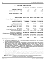
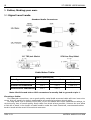
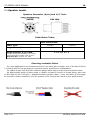
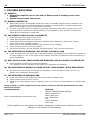
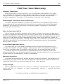
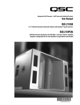
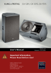
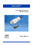
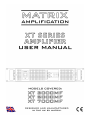
1
XT SERIES USER MANUAL
CONTENTS:
Page
Thank You
Congratulations on the purchase of your new
Matrix Professional Power Amplifier.
Matrix amplifiers are the result of many
decades of experience in the design of
exceptionally robust and reliable amplifiers.
They are designed to breathe life into your
sound, by controlling your speakers with
exacting authority through the
uncompromising delivery of clean,
undistorted power, from a package which is
smaller and lighter than you might expect
for the performance it delivers.
This manual will help you to get the most
from your amplifier. For maximum benefit, it
is recommended that all instructions and
warnings are carefully read. Also be sure to
read the notices regarding correct wiring of
output connectors as this impacts the
operation of the amplifier.
For warranty service, please retain your
receipt and all packaging that comes with
the amplifier, as it has been specifically
designed to transport the amplifier safely.
Unpacking
Thank You
1
1. Features and Innovations
2
2. Specifications
3-4
2.1 Technical specifications
2.2 Basic Schematics
3. Interface Elements
5-7
3.1 Front Panel
3.2 Rear Panel
4. Recommended Usage
5. Cables, Making your own
8
9-11
6. Trouble Shooting
12
7. Warranty
13
8. Declaration of CE Conformity
14
CAUTION:
OBSERVE ALL SAFETY AND USAGE
INSTRUCTIONS TO AVOID POSSIBLE DAMAGE
TO EQUIPMENT AND EXPOSURE TO HAZARDS
(THIS SYMBOL UNIVERSALLY FLAGS CAUTION
NOTICES)
Please unpack and inspect your new
amplifier for any damage that may have
occurred during transit. If damage is found,
notify the carrier immediately.
Note: A suitable mains lead is provided and
can be found packaged with the amplifier.
PLEASE RETAIN ALL FACTORY PACKAGING
FOR ANY FUTURE POSTAL TRANSIT.
LETHAL VOLTAGES PRESENT AT SPEAKER
TERMINALS AND INSIDE THE AMPLIFIER;
ENSURE ALL WIRING IS SAFE AND CORRECT
BEFORE USE.
(THIS SYMBOL ALSO UNIVERSALLY FLAGS
ELECTRICAL HAZARDS)
DO NOT OPEN THE AMPLIFIER; LEAVE ALL
INTERNAL SERVICE OPPERATIONS TO A
QUALIFIED TECHNICIAN.
REV.1.21
MATRIX AMPLIFICATION
XT SERIES USER MANUAL
2
1. Features and Innovations
All our amplifiers have been designed to give the best possible performance for their
intended application and are based on our own uncompromising, time proven MOSFET designs.
These take advantage of components which will stand the test of time and give the best possible
performance in a small, exceptionally light weight package.
We only have the desire to provide our users with the best possible solutions and continue to
look for ways to improve upon them.
Amplifier features:
•
Class AB, MOSFET amplifier topology.
•
An unprecedentedly powerful and stable Switch Mode Power Supply.
Designed without compromise, to exceed the performance of the previous linear supply
models; whilst offering a weight advantage rarely seen even in other SMPS amplifiers.
•
•
•
.
.
Soft Start Circuit.
The power supply is designed not to draw excessive current on startup - Prevents the 'thump'
as occasionally occurs with other equipment, from tripping fuses and breakers.
.
Protection against Short Circuit and Overheating.
.
Speaker Protection relay with delay to inhibit switch on thump.
The speakers are disconnected during power up/down.
•
Fully balanced XLR Inputs.
•
Temperature regulated, High Speed Fan Cooling.
A new high speed fan is utilised to ensure maximum reliability by allowing for far greater
cooling latitude (The amplifier vents hot air through rear connector panel).
.
REV.1.21
MATRIX AMPLIFICATION
3
XT SERIES USER MANUAL
2.1 Technical Specifications
XT 3000 MF
XT 5000 MF
XT 7000 MF
Number of Channels:
2
2
2
Watts Per Channel at - 8 Ω:
1000
1800
2500
Watts Per Channel at - 4 Ω:
1500
2500
3500
Watts Per Channel at - 2 Ω:
-
-
-
-
-
-
-
-
-
Supply Voltage: 230V +/- 15% 230V +/- 15% 230V +/- 15%
Average Supply Current, Full Load:
16A
27A
32A
Mains Connector: 32A Powercon 32A Powercon 32A Powercon
Frequency Response:
8–24,000 Hz
8–24,000 Hz
8–24,000 Hz
Signal to Noise Ratio
(ref. Full power 1kHz):
99 dB
101 dB
102 dB
THD (1kHz, full power):
0.07%
0.07%
0.07%
THD (20Hz - 20kHz, full power):
<0.1%
<0.1%
<0.1%
Slew Rate:
65 V/µs
69 V/µs
69 V/µs
Damping Factor (ref. 8R, 100Hz):
>400
>550
>650
Input Level Sensitivity:
1.2v / +4 dBu
1.2v / +4 dBu
1.2v / +4 dBu
Cooling Fan Arrangement: 2x 80mm ext. 2x 80mm ext. 2x 80mm ext.
(Temperature controlled dual speed fans) 1x Internal fan 1x Internal fan 1x Internal fan
Cooling Airflow Direction:
Front to Back
Front to Back
Front to Back
Dimensions (mm): 482 X 88 X 370 482 X 88 X 370 482 X 88 X 370
Weight:
10 Kg
10 Kg
10 Kg
Operating Environment:
The amplifier is designed for use in environments which protect it from rain, unusually
high air humidity and temperature.
● When mounting inside, ensure that the amplifier is securely bolted into a rack using all
available fixing points where possible. Otherwise place on a surface where it cannot be
easily displaced, Potentially causing damage/injury. Ensure That the location will not
expose the amplifier to spillage of liquids/drinks, sprays/vapours or high humidity. Ensure
the amplifier is installed in a place which is not subject to abnormally high temperatures
and maintain sufficient ventilation to prevent overheating.
● For temporary use outside, apply similar caution; however be extra sure to ensure
placement accounts for changing weather conditions and that extreme wind/rain/heat will
not find its way to equipment.
● When taking any equipment from a cold environment (unheated storage, vehicles, etc),
into a warm one, allow the equipment time to acclimatise to the ambient temperature, as
condensation is likely to form in the amplifier, potentially causing it to malfunction if put
into service too soon.
●
Note: Our policy of continuous improvement may lead to the above specifications being
exceeded prior to documentation being updated.
REV.1.21
MATRIX AMPLIFICATION
XT SERIES USER MANUAL
4
2.2 Basic Schematics.
Output Connections:
REV.1.21
MATRIX AMPLIFICATION
5
XT SERIES USER MANUAL
.
3.1 Interface Elements, Front Panel.
.
(1) Power Switch
This switch controls the power supply to the amplifier. There is a short delay on power-up,
this is to avoid switch-on "thump" which could damage the loudspeakers.
.
(2) Gain Controls
The level of each Channel is individually adjusted by these controls.
Rotating these controls fully clockwise, results in no attenuation to the incoming audio signals.
.
(3) Indicator Section, Status:
a. Power Indicators
This indicator shows when the amplifier is on and each channel is receiving power.
(4) Indicator Section, Signal levels:
a. Output Level Display
These show the (Peak) output level of the amplifier for each channel, in both Stereo and
Mono modes. It is useful to note for trouble shooting, that the sensors for the Output Level
Display, detects levels after the output relays. Therefore if the display is operating, a signal is
present at the speaker sockets.
b. Limit Level Indicators
These illuminate to show that the amplifiers limiting circuitry is active. Repeated
illumination indicates that the amplifier is being driven excessively and a reduction
in level is recommended.
c. Protect Indicators
These indicators light briefly during the power up cycle and also light should a
fault occur. Illumination of the protect indicators, shows that the output of the
amplifier has been disconnected by means of an internal relay to protect connected
speaker systems from being damaged by the fault.
.
.
REV.1.21
MATRIX AMPLIFICATION
XT SERIES USER MANUAL
6
3.2 Interface Elements, Rear Panel.
.
(5) Cooling Fan Outlet
.
Hot air exits here. M ake sure all rear (and front) ventilation paths are free
from obstruction and air flows freely, otherwise the amplifier will trip into thermal
protect mode prematurely and in some extreme circumstances damage may occur.
(6) Output Connectors
.
The Output sockets are Neutrik Speakons and accept a Neutrik NL4FC plug. Avoid inferior
alternatives, as they may present numerous hazards due to less than ideal construction.
Insert the plug and turn clockwise until you hear it click. This ensures correct connection has
been made. To remove, pull back the levered tab and turn anti-clockwise.
Ready-made, sensibly priced, quality interconnection leads suitable for use with the amplifier
should be easy to source. However, with sufficient skill, it is possible to make/modify leads for
the task. proceed to Chapter 5. - “Cables, Making your own”.
.
●
Both pin pairs (+1 -1 and +2 -2) in each socket are connected in parallel to allow for
greater power handling capability to the same or multiple destination loads.
NOTE: Both pin pairs (+1 -1 and +2 -2) in each socket are connected in parallel to
the indicated channels.
In addition please ensure that cables purchased or assembled for the purposes of
connecting the amplifiers outputs are suitable for this task. If unsure, please
consult a qualified technician. Failure to use appropriate wiring could damage the
amplifier, associated equipment or present a fire/electrocution risk under certain
circumstances.
CAUTION: Whilst we recommend that Neutrik speakon connections are always
used for the safest way of connecting to the amplifier, the option is also provided
to use 1/4” jack connections with these outputs. Take extra care when connecting
leads to ensure that these are not accidentally connected to the inputs and outputs
of other equipment not designed specifically to do so, otherwise damage to
equipment is likely to occur.
Take extra care with 1/4” jack speaker connections, the exposed plug end can
present an electric shock hazard, also never allow the outputs to be shorted,
equipment damage may occur. Finally, note that standard 1/4” interconnect leads
are not suitable for connection between amplifier and loudspeaker, choose one
designed for this specific task for safe operation and optimal performance.
REV.1.21
MATRIX AMPLIFICATION
7
XT SERIES USER MANUAL
(7) Input Signal Sockets
.
Signal input connections are provided via Female XLR sockets.
Industry standard Balanced XLR format, which helps ensure interference and noise free
connections between equipment.
Ready-made, sensibly priced, quality interconnection leads suitable for use with the amplifier
should be easy to source. However, with sufficient skill, it is possible to make/modify leads for
the task. Proceed to Chapter 5. - “Cables, Making your own”.
(9)Power Connection
.
Mains power is supplied to the amplifier by a standard 32 Amp Powercon mains
socket. An appropriate mains lead is supplied with the amplifier.
Note: The amplifier requires a stable power supply to function as intended. Ensure
that the power source (mains power supply, generator, etc.) is suitable for this
application and adequate power is available. Poorly selected power sources result
in sub-optimal performance, increased likelihood of tripping breakers, blowing
fuses and in extreme situations damage to equipment may occur.
Should the fuse in the mains lead blow for any reason, it must be replaced
with a fuse of the correct rating. This should be 13 amps for the models listed in
this manual. However, if there is any reason to believe that a malfunction caused
the fuse to blow, stop using the equipment immediately and take the amplifier to
an authorised service engineer for servicing.
REV.1.21
MATRIX AMPLIFICATION
XT SERIES USER MANUAL
8
4. Recommended Usage:
To ensure your speaker and amplifier system functions optimally, it is advised to read
through everything covered in this manual.
Safety precautions and appropriate usage recommendations for specific connections and
features are noted in the previous section.
.
4.1 Matching Speakers to the amplifier:
.
When matching loudspeakers appropriately to the available amplification refer to the
recommendations provided by the cabinet/speaker manufacturer. If unsure, please consult a
qualified technician.
Typically we will note however, that loudspeaker manufacturers will recommend that the the
amplifiers output power matches the specified power of the loudspeaker fairly closely. This
ensures that the speaker does not receive more power than it is able to handle without potential
failure / damage or unintended, distortion of sound occurring.
Also ensuring the amplifier is not too small to drive the loudspeaker to its full output level is
important in preventing accidental damage through hard clipping resulting from attempting to
drive the amplifier outside of its full output capability – this can easily prove fatal for even the
largest of loudspeakers and may damage the amplifier too. It remains however the users
responsibility to be sure that correct levels are maintained.
REV.1.21
MATRIX AMPLIFICATION
9
XT SERIES USER MANUAL
5. Cables, Making your own.
5.1 Signal Level Leads.
Standard Audio Connectors:
Cable Maker Table:
Cable Connections:
Cable Type:
Ground/Screen Red/Central Cable
White
balanced to balanced
1 to 1
2 to 2
3 to 3
balanced to unbalanced
1 to 1
2 to 2
3 tied to 1
unbalanced to unbalanced
1 to 1
2 to 2
-
Note: Shell Ground tab on XLR connectors is usually tied to ground at pin 1.
Choosing a Cable:
For balanced connections, use a good quality metal braid screened cable with two inner wire
cores; this will usually be clearly marketed as pro audio/microphone signal cable.
For long cable runs in excess of 6m/20ft, try to use cables with lower capacitance ratings, to
minimise any loss of sound quality. Keep cable runs short where possible, however be sure allow
a little bit of slack in the length of cable used to make the lead. Stretched, overstressed cables
tend to break at the most inconvenient moments.
REV.1.21
MATRIX AMPLIFICATION
XT SERIES USER MANUAL
10
5.2 Speaker Leads.
Speakon Connector (4 pin) and 1/4” Jack:
Cable Maker Table:
Cable Connections:
Cable Type:
Single Channel, 2 core lead.
Single Channel, 4 core lead.
For increased power handling in one cable.
Check destination speaker uses all pins !
Outputs A & B - 4 ohms min. load
+ and -
+ and -
1 to 1
1 to 1 and 2 to 2
Choosing a suitable Cable:
For most applications we recommend a twin core cable with a copper core of at least 2.5mm 2
/ 12 awg & sold for the purpose of connecting power amplifiers to loudspeakers.
For cables longer than 6m/20ft a heavier gauge cable may provide improved performance.
An approximate guide of cable sizing in relation to that of a pencil is shown below, also note
on the right the thin 'bell wire' / budget domestic speaker cable... never use cable of this gauge
to connect to power amplifiers, this can present a fire risk and will result in poor performance.
REV.1.21
MATRIX AMPLIFICATION
11
XT SERIES USER MANUAL
6. TROUBLE SHOOTING.
.
(1) ALWAYS:
● Ensure the amplifier has no less than 4 Ohms worth of loading across each
channel.
● Ensure wiring is safe and correct.
.
(2) NORMAL ARTIFACTS:
●
●
.
When heavily driven, the amplifier itself may make a noticeable hissing sound in relation to the
supplied signal. This is a normal phenomenon relating to the behaviour of certain components
which vibrate slightly under the high powers involved.
The Fans on the XT Series may appear to generate more noise than earlier models, they run at
higher speeds to increase the cooling efficiency of the amplifiers. They will also increase their
speed when the amplifier is under load.
(3) THE POWER LIGHTS DO NOT ILLUMINATE
1.
2.
3.
4.
.
Check that the mains supply is turned on.
Check that the mains switch is turned on.
Check Mains lead for damage & check fuse. Replace lead if damaged, replace fuse if blown.
Check internal fuse. Replace if blown.
(same type of fuse specified/installed must be used, do not change)
5. If fuse re-blows refer to service personnel.
6. If fuse has not blown, but the amplifier still malfunctions, refer to service personnel.
(4) THE AMPLIFIER IS WORKING, BUT OUTPUT VOLUME IS LOW
.
●
.
Check the signal from the input source and signal cables. The amplifiers are designed to operate at
an input voltage of 1.2V. If the signal source is below this refer to qualified service personnel for a
minor modification.
(5) AMP OUTPUT LEVEL INDICATORS ARE WORKING, BUT NO SOUND IS COMING OUT
.
●
Check Speakon connectors are securely attached.
(The amplifier must be operating if the output level indicators are working)
.
(6) THE AMPLIFIER IS GIVING A LOWER OUTPUT THAN NORMAL, WITH DISTORTION
.
●
.
The protection circuits (current clamps) are operating. Check all leads for short-circuits. Try
another set of leads and loudspeakers.
(7) THE AMPLIFIER IS OVERHEATING
.
●
●
●
.
Check that the fan is not obstructed with debris, and is rotating freely.
Check speaker leads for short circuits.
Check to see that amplifier output 'negatives' have -not- been connected together in bundled cable
looms.
If any of these, or other symptoms persist, Please contact us with the details below for help,
advice and service:
Contact Details:
Email: [email protected]
Address:
MATRIX AMPLIFICATION LIMITED,
Matrix Amplification,
Little Castle Farm,
Pen-Y-Park Road,
Usk,
United Kingdom,
NP15 2BX.
If the amplifier is to be shipped, use factory packaging or other secure method as transit
damage is not covered by the warranty.
REV.1.21
MATRIX AMPLIFICATION
XT SERIES USER MANUAL
12
Full Two Year Warranty
Summary of Warranty
.
Matrix Amplification Limited, warrant to you, the ORIGINAL PURCHASER of each Matrix
Power Amplifier, for a period of 2 (two) years from the date of purchase, that the amplifier is
free from defects in materials and workmanship and we further warrant the new Matrix
Amplifier, regardless of the reason of failure except as excluded in this warranty.
Items Subject to Exclusion from this Warranty
.
This Matrix Amplifier Warranty is in effect only for failure of a new Matrix Amplifier which
occurred during the warranty period. It does not cover any product that has been damaged
because of any misuse be it intentional or otherwise, accident, negligence, or loss which is
covered under any insurance.
What the Warranter Will Do
.
We will remedy any defect, regardless of the reason for failure (except as excluded above),
by repair or replacement. Warranty work can only be performed at our authorised distributors or
at Matrix Amplification Limited. We will remedy the defect and ship the product from the service
centre or our own factory within a reasonable time after receipt of the defective product. All
expenses in remedying the defect, including freight costs from ourselves to you (within mainland
UK) will be borne by us. You must bear the costs of shipping the product to our authorised
service centre or factory.
How to Obtain Warranty Service
.
You must notify us of your need for warranty service not later than the expiry of your
warranty. The amplifier must be shipped in a factory pack, which if required can be obtained
from us at a modest charge. The amplifier must be sent to us carriage paid and insured.
Corrective action will be taken within a reasonable time from the date of receipt of the
defective product by us or our authorised service centre. If repairs made by us or our authorised
service centre are not satisfactory, contact us immediately.
Warranty Alterations
..
No person has the authority to enlarge, amend or modify this warranty. The warranty is not
extended by the length of time which you are deprived of the use of the amplifier. Repairs and
replacement parts will only carry the unexpired portion of this warranty.
Design Changes
.
Matrix Amplification Limited has a policy of continuous improvement to designs without
notice and with no obligation to make corresponding changes in products previously
manufactured.
Your Statutory Rights are Unaffected by this Warranty
REV.1.21
MATRIX AMPLIFICATION
13
XT SERIES USER MANUAL
Declaration of CE Conformity
.
Issuers Name and Address:
Andrew Hunt,
MATRIX AMPLIFICATION LIMITED,
Cordes House, Factory Road, Newport, Gwent, United Kingdom.
NP20 5FA
Products:
XT3000MF / X5000MF / XT7000MF
Equipment Type:
Commercial Audio Power Amplifiers.
Safety Standard:
AMD1: 2005 and IEC
60065: 2001 7th Ed.
Safety Requirements - Audio Video and Similar Electronic Apparatus.
EMC Standards:
EN 61000-4-2:2001
Electrostatic Discharge Immunity (Environment E2-Criteria B, 4k V Contact, 8k V Air Discharge).
EN 61000-4-3:2006
Radiated, Radio-Frequency, Electromagnetic Immunity (Environment E2, criteria A).
EN 61000-4-4:2007
Electrical Fast Transient/Burst Immunity (Criteria B).
EN 61000-4-5:2006
Surge Immunity (Criteria B).
EN 61000-4-6:2006
Immunity to Conducted Disturbances Induced by Radio-Frequency Fields (Criteria A).
EN 61000-4-11:2001
Voltage Dips, Short Interruptions and Voltage Variation.
EN 55103-1:1997
Electromagnetic Compatibility - Product Family Standard for Audio, Video, Audio-Visual and
Entertainment Lighting Control Apparatus for Professional Use, Part 1: Emissions.
EN 55103-1:1997
Magnetic Field Emissions-Annex A @ 10 cm and 20 cm.
EN 55103-2:1997
Electromagnetic Compatibility - Product Family Standard for Audio, Video, Audio-Visual and
Entertainment Lighting Control Apparatus for Professional Use, Part 2: Immunity.
EN 61000-3-2:2005
and AMD1: 2008
Limits for Harmonic Current Emissions (equipment input current less than or equal to 16 A per
phase).
EN 55022:2006
Limits and Methods of Measurement of Radio Disturbance Characteristics of ITE: Radiated, Class
B Limits; Conducted, Class A.
EN 61000-3-3:2008
Limitation of Voltage Fluctuations and Flicker in Low-Voltage Supply Systems Rated Current less
than or equal to 16A.
Declaration:
I certify that the product identified above conforms to the requirements of the EMC Council
Directive 89/336/EEC as amended by 92/31/EEC, and the Low Voltage Directive 73/23/EES as
amended by 93/68/EEC.
Signatories:
Date of Issue:
Andrew Hunt,
28 December 2012.
Managing Director.
REV.1.21
MATRIX AMPLIFICATION