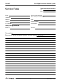
1
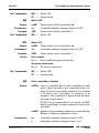
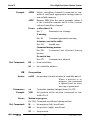
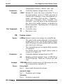
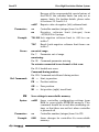
NanoPZ™
Ultra-High Resolution
Motion System
USER’S MANUAL
NanoPZ
Ultra-High Resolution Motion System
Warranty
Newport Corporation warrants that these products will be
free from defects in material and workmanship and will
comply with Newport’s published specifications at the time
of sale for a period of one year from date of shipment.
If found to be defective during the warranty period, products
will either be repaired or replaced at Newport's option.
To exercise this warranty, write or call your local Newport
office or representative, or contact Newport headquarters in
Irvine, California. You will be given prompt assistance and
return instructions. Send the products, freight prepaid, to the
indicated service facility. Repairs will be made and the
products returned freight prepaid. Repaired products are
warranted for the remainder of the original warranty period
or 90 days, whichever occurs last.
Limitation of Warranty
The above warranties do not apply to products which have
been repaired or modified without Newport’s written
approval, or products subjected to unusual physical, thermal
or electrical stress, improper installation, misuse, abuse,
accident or negligence in use, storage, transportation or
handling. This warranty also does not apply to fuses,
batteries, or damage from battery leakage.
THIS WARRANTY IS IN LIEU OF ALL OTHER WARRANTIES,
EXPRESSED OR IMPLIED, INCLUDING ANY IMPLIED WARRANTY
OF MERCHANTABILITY OR FITNESS FOR A PARTICULAR USE.
NEWPORT CORPORATION SHALL NOT BE LIABLE FOR ANY
INDIRECT, SPECIAL, OR CONSEQUENTIAL DAMAGES
RESULTING FROM THE PURCHASE OR USE OF ITS PRODUCTS.
First printing 2005
© 2006 by Newport Corporation, Ir vine, CA. All rights
reserved. No part of this manual may be reproduced or
copied without prior written approval of Newport
Corporation.
This manual is provided for information only, and product
specifications are subject to change without notice. Any
change will be reflected in future printings.
Newport Corporation
1791 Deere Avenue
Irvine, CA, 92606, USA
Part No. 44019-01, Rev. E
44019-01 Rev. E — 05/10
ii
NanoPZ
Ultra-High Resolution Motion System
Table of Contents
Warranty .................................................................................ii
EU Declaration of Conformity .............................................vi
Preface .............................................................................vii
Confidentiality & Proprietary Rights ....................vii
Service Information.................................................vii
Sales, Tech Support & Service..............................viii
Newport Corporation USA Calling Procedure ....viii
1.0
1.1
1.2
1.3
2.0
2.1
2.2
2.3
2.4
2.5
2.6
2.7
— Safety Precautions ..........................................1
Definitions and Symbols ...........................................1
European Union CE Mark .........................................1
C-US CSA Mark ...........................................................1
Direct Current (DC) ...................................................1
Warnings and Cautions .............................................2
General Warnings ......................................................2
General Cautions .......................................................2
Manual Conventions .................................................3
— Features & Specifications .................................3
NanoPZ™ System Overview ....................................3
PZA12 Actuator..........................................................4
General Use ................................................................4
Motion Principle ........................................................4
Mechanical Compatibility ........................................6
PZA12 Design Details ................................................7
PZC200 Controller/Driver .........................................7
PZC200 Specifications...............................................9
PZC-SB Switchbox....................................................10
PZC-SB Specifications .............................................11
NSC-PS25 Power Supply..........................................12
NSC-PS25 Specifications .........................................13
NSC-JB RS-485 Junction Box...................................14
NSC-JB Specifications..............................................15
NSC-485-232-I RS-485 to RS-232 Converter............15
iii
44019-01 Rev. E — 05/10
NanoPZ
Ultra-High Resolution Motion System
2.8
NSC-485-232-I Specifications...................................16
NanoPZ System Environmental Specifications ....16
3.0
3.1
3.2
3.3
3.4
—Getting Started ....................................................17
Unpacking and Handling.........................................17
Inspection for Damage ............................................17
Inventory of Parts....................................................17
Interconnecting Components ................................18
4.0
4.1
4.2
4.3
— Local Operation ................................................23
Operating Modes .....................................................23
Local (Manual) Control...........................................23
Reading the LED Status Lights...............................25
LED Indicator on PZC200 Controller .....................25
LED Indicators on PZC-SB Switchbox ...................25
5.0
5.1
5.2
5.3
5.4
5.5
5.6
— Utility Software .................................................26
Overview...................................................................26
RS-232 Communications Setup ..............................26
Software Installation ...............................................27
Controller Initialization...........................................28
Network Scan ...........................................................29
Working with the Main Screen ...............................30
Move Tab ..................................................................31
Setup Tab..................................................................32
View all Tab ..............................................................33
Status Tab .................................................................34
About Tab .................................................................35
6.0
6.1
— ASCII Command Set .........................................36
Command Set Introduction ....................................36
Address Field ...........................................................36
Set or Query Commands ........................................36
Saving Settings to Non-Volatile Memory ..............37
Motion Commands ..................................................37
Command Set Summary .........................................38
6.2
44019-01 Rev. E — 05/10
iv
NanoPZ
Ultra-High Resolution Motion System
6.3
Command Set Details ..............................................39
BX
Scan switchbox .............................................39
BZ
Restore EEPROM content to default ..........39
ID
Actuator description ....................................40
JA
Start jog motion ............................................41
MF Motor OFF......................................................42
MO Motor ON .......................................................42
MX Select switchbox channel ............................42
OR Zero position .................................................43
PH
Get hardware status .....................................44
PR
Position relative ............................................45
RS
Reset controller ............................................46
SA
Set controller address ..................................46
SL
Set negative (left) travel limit......................46
SM Save settings to non-volatile memory........47
SR
Set positive (right) travel limit....................48
ST
Stop motion ...................................................49
TE
Read error code ............................................49
TP
Read current position ..................................50
TS
Controller status ...........................................51
VE
Read controller firmware.............................51
7.0
7.1
7.2
— Maintenance & Service ...................................52
Enclosure Cleaning..................................................52
Technical Support ...................................................52
Service Form.........................................................................53
v
44019-01 Rev. E — 05/10
NanoPZ
Ultra-High Resolution Motion System
EU Declaration of Conformity
We declare that the accompanying product, identified with the “
”
mark, complies with requirements of the Electromagnetic
Compatibility Directive, 89/336/EEC and the Low Voltage Directive
73/23/EEC.
Product Name: NanoPZ™
Model Number: PZA12 NanoPZ actuator, PZC200 NanoPZ controller,
PZC-SB switchbox
Year
mark affixed: 2005
Type of Equipment: Electrical equipment for measurement, control
and laboratory use.
Standards Applied:
Compliance was demonstrated to the following standards to the
extent applicable:
BS EN61326-1: 1997+A1+A2+A3 “Electrical equipment for
measurement, control and laboratory use – EMC requirements”.
This equipment meets the CISPR 11 Class A Group 1 radiated and
conducted emission limits:
• BS EN 61000-3-2:2001, Harmonic current emissions, Class A.
• BS EN 61000-3-3:2002, Voltage fluctuations and flicker.
• BS EN 61010-1:2001, 2nd Edition “Safety requirements for electrical
equipment for measurement, control and laboratory use”.
Alain Danielo
Dan Dunahay
VP European Operations
Systems
Zone Industrielle
45340 Beaune-la-Rolande, France
Director of Quality
44019-01 Rev. E — 05/10
vi
1791 Deere Avenue
Irvine, Ca. USA
NanoPZ
Ultra-High Resolution Motion System
Preface
Confidentiality & Proprietary Rights
Reservation of Title
The Newport programs and all materials furnished or produced
connected there-with (“Related Materials”) contain trade
secrets of Newport and are for use only in the manner expressly
permitted. Newport claims and reserves all rights and benefits
afforded under law in the Programs provided by Newport
Corporation.
Newport shall retain full ownership of Intellectual Property
Rights in and to all development, process, align or assembly
technologies developed and other derivative work that may be
developed by Newport. Customer shall not challenge, or cause
any third party to challenge, the rights of Newport.
Preservation of Secrecy and Confidentiality and Restrictions
to Access
Customer shall protect the Newport Programs and Related
Materials as trade secrets of Newport, and shall devote its best
efforts to ensure that all its personnel protect the Newport
Programs as trade secrets of Newport Corporation. Customer
shall not at any time disclose Newport's trade secrets to any
other person, firm, organization, or employee that does not
need (consistent with Customer's right of use hereunder) to
obtain access to the Newport Programs and Related Materials.
These restrictions shall not apply to information (1) generally
known to the public or obtainable from public sources; (2)
readily apparent from the keyboard operations, visual display,
or output reports of the Programs; 3) previously in the
possession of Customer or subsequently developed or acquired
without reliance on the Newport Programs; or (4) approved by
Newport for release without restriction.
Service Information
This section contains information regarding factory service for
the source. The user should not attempt any maintenance or
service of the system or optional equipment beyond the
procedures outlined in this manual. Any problem that cannot be
resolved should be referred to Newport Corporation.
vii
44019-01 Rev. E — 05/10
NanoPZ
Ultra-High Resolution Motion System
Sales, Tech Support & Service
North America & Asia
Europe
Newport Corporation
MICRO-CONTROLE Spectra-Physics S.A
1791 Deere Ave.
Irvine, CA 92606, USA
1, rue Jules Guesde – Bât. B
ZI Bois de l’Épine – BP189
91006 Evry Cedex
France
Sales
(949) 253-1461 or (800) 222-6440 x31461
Sales & Technical Support
e-mail: [email protected]
+33 (0)1.60.91.68.68
Technical Support
e-mail: [email protected]
(949) 253-1406 or (800) 222-6440 x31406
Service & Returns
e-mail: [email protected]
+33 (0)2.38.40.51.55
Service, RMAs & Returns
(949) 253-1694 or (800) 222-6440 x31694
e-mail: [email protected]
Newport Corporation USA Calling Procedure
If there are any defects in material or workmanship or a failure to meet
specifications, promptly notify Newport's Returns Department by calling
1-800-222-6440 (US customers only) or by visiting our website at
www.newport.com/returns within the warranty period to obtain a Return
Material Authorization Number (RMA#). Return the product to Newport
Corporation, freight prepaid, clearly marked with the RMA#, and we will
either repair or replace it at our discretion. Newport is not responsible
for damage occurring in transit and is not obligated to accept products
returned without an RMA#. Email: [email protected]
When calling Newport Corporation, please provide the Customer Care
Representative with the following information:
• Your Contact Information
• Serial number or original order number
• Description of problem (i.e., hardware or software)
To help our Technical Support Representatives diagnose your problem,
please note the following conditions:
• Is the system used for manufacturing or research and development?
• What was the state of the system right before the problem?
• Have you seen this problem before? If so, how often?
• Can the system continue to operate with this problem? Or is the system non-operational?
• Can you identify anything that was different before this problem
occurred?
44019-01 Rev. E — 05/10
viii
NanoPZ
Ultra-High Resolution Motion System
NanoPZ™
Ultra-High Resolution Motion System
1.0
Safety Precautions
1.1 Definitions and Symbols
1.1.1
European Union CE Mark
Figure 1: CE Mark.
The CE mark indicates that the equipment has been
designed and tested to comply with all applicable
European Union (CE) regulations.
1.1.2
C-US CSA Mark
®
C
US
Figure 2: CSA Mark.
The presence of the C-US CSA mark indicates that the
equipment has been designed, tested and certified as
complying with all applicable US and Canadian safety
standards.
1.1.3
Direct Current (DC)
Figure 3: Direct Current Symbol.
This symbol indicates that the equipment is suitable for
DC power only.
1
44019-01 Rev. E — 05/10
NanoPZ
Ultra-High Resolution Motion System
1.2 Warnings and Cautions
The following are definitions of Warnings, Cautions and
Notes that may be used in this manual to call your
attention to important information regarding your safety,
to the safety and preservation of your equipment, and to
important tips.
WARNING
Situation has potential to cause bodily harm or death.
CAUTION
Situation has potential to cause damage to property or
equipment.
NOTE
Additional information the user or operator should consider.
1.2.1
General Warnings
Observe these general warnings when operating or servicing
this equipment.
• Read all warnings on the unit and in the operating instructions.
• Do not use this equipment in or near water.
• Only connect the power cord to a grounded power outlet.
• Route power cords and other cables so they are not likely to be damaged.
• Disconnect power before cleaning the equipment. Do not use liquid or
aerosol cleaners; use only a damp lint-free cloth.
• To avoid explosion, do not operate this equipment in an explosive
atmosphere.
1.2.2
General Cautions
Observe these cautions when operating or servicing this
equipment:
• Use only specified replacement parts.
• Follow precautions for static sensitive devices when handling this
equipment.
• This product should only be powered as described in this manual.
• There are no user-serviceable parts inside the NanoPZ system components.
• If this equipment is used in a manner not specified within this manual,
the protection provided by the equipment may be impaired.
• Do not position this equipment in a location that would make it difficult to disconnect the AC power cord.
44019-01 Rev. E — 05/10
2
NanoPZ
Ultra-High Resolution Motion System
1.3 Manual Conventions
The following conventions are used in this manual:
• Acronyms appear on the first occurrence enclosed in
parentheses following their definition. An acronym is a
word formed from the initial letters of a string of
words. Example: Read Only Memory (ROM).
• Italics or boldface text are used as an alternative to
quotation marks to highlight special text, such as keyboard keys, onscreen buttons, or text entries.
Examples: Press Enter. AU command.
2.0
Features & Specifications
2.1 NanoPZ™ System Overview
Newport’s NanoPZ family of piezo motor actuators and
controllers is designed to provide cost-effective,
nanometer-scale remote positioning of manual stages
and optical mounts in a wide range of opto-mechanical
systems. NanoPZ system components (as of June 2005)
may include one or more of the following:
Model
Description
PZA12
NanoPZ actuator, 12.5 mm travel.
PZC200
Hand-held controller for PZA12.
NSC-PS25
AC power supply for PZC200.
NSC-PSC1
1 meter power supply output cable.
NSC-PSC3
3 meters power supply output cable.
NSC-485-232-I
RS-485 to RS-232 converter.
USB-232
RS-232 to USB converter. Requires Windows™ operating
system.
NSC-JB
Junction box to split 1 RS-485 channel into to 5 channels.
NSC-CB1
0.3 meter RS-485 cable.
NSC-CB3
2.7 meter RS-485 cable.
PZC200-KT
Kit including 1 x PZA12 actuator, 1 x PZC200 controller,
1 x NSC-PC25 power supply, and 1 x NSC-PSC3 power
supply cable.
PZC-SB
Switchbox allowing one PZC200 to drive up to 8 PZA12
actuators. Included cables:
41791-01: 1.8 m (6 ft) power cable to controller.
3
44019-01 Rev. E — 05/10
NanoPZ
Ultra-High Resolution Motion System
15769-02: 1.8 m (6 ft) driver cable to controller.
NSC-CB2: 1.8 m (6 ft) RS-485 cable to controller.
2.2 PZA12 Actuator
Figure 4: PZA12 Actuator.
2.2.1
Figure 5: Mounted PZA12.
General Use
The PZA12 is a piezo motor driven actuator allowing
nanometer-scale remote adjustment of manual-positioning
stages and opto-mechanical components over large
distances, in hard to reach spaces and in hazardous handsoff applications.
Typical applications include fiber alignment, micro
assembly, cell manipulation, probing, alignments of laser
cavities, phase-matching, and laser beam stabilization.
PZA12 actuators incorporate an innovative piezo stepping
motor that ensures highly reliable motion with 30 nm
sensitivity over 12.5 mm travel and no loss of position
when power is removed.
To avoid contact surface wear, PZA12 actuators feature a
non-rotating tip. And a cover prevents damage to the drive
train and protects from dust, debris and other pollutants.
PZA12 actuators are compatible with an array of Newport
products. For details please refer to the latest Newport
catalog or the Newport web page (www.newport.com).
The PZA12 actuators get controlled by the PZC200
controller either directly or via one of the eight output
ports of a PZC-SB switchbox.
2.2.2
Motion Principle
PZA12 actuators base on a piezo stepping motor. This
motor consists of several multi-leg piezo elements. When
44019-01 Rev. E — 05/10
4
NanoPZ
Ultra-High Resolution Motion System
supplying these piezo elements with a special voltage
pattern, the legs lift up, move forward and come down
again similar to human motion.
A number of these piezo elements are arranged in a circle
and coupled by friction to a rotating nut. This nut, in turn,
is coupled to a screw that is blocked in rotation and that
generates the resulting forth and back motion of the
actuator tip.
On average, one cycle, or one step of the piezo motor
results in a linear motion of the actuator tip of approx.
160 nm. Further electronic break-down of steps into 16
micro-steps results in an average motion of approx. 10 nm
per micro-step.
IMPORTANT NOTE
Because of the friction coupling between the piezo legs and the rotating
nut, the actual step size is not 100% accurate or repeatable. It can vary
from actuator to actuator and depends further on load, speed, direction
of motion, and other parameters. For highly repeatable or accurate positioning tasks an additional external feedback should be used.
PZA actuators feature jam-nut proof hard stops that limit
the max./min. travel. In addition, software limits can be set
to further reduce the travel range and to avoid motor
stalling. Anyhow, motor stalling does not damage the
actuator.
2.2.3
5
44019-01 Rev. E — 05/10
NanoPZ
Ultra-High Resolution Motion System
Mechanical Compatibility
The PZA12 has a 0.375” x 40 pitch threaded shaft that is
compatible with many Newport and other manufacturers
mounts and manual stages. With this common interface
PZA12 actuators can directly replace manual adjustment
screws in many existing setups and provide a huge variety
of combinations. A mounting nut and wrench is included
with each actuator. For a complete list of Newport
compatible mechanics, please refer to the latest Newport
catalog or the Newport web page (www.newport.com).
.37 to .47
(9.5 to 12)
THD 3/8”-40 UNS2A
-.00020
Ball ø.16
(Ø 3.97)
ø.37 -.00055
(Ø 9.5 g6)
ø.83
(Ø 21)
ø.24
(Ø 6)
.63
(15.9)
1.03 ±.25
(26.23 ±6.35)
1.9
(49.1)
Figure 6: Dimensions, PZA12 Linear Actuator.
44019-01 Rev. E — 05/10
6
NanoPZ
Ultra-High Resolution Motion System
2.2.4
PZA12 Design Details
Base material
Aluminum
Drive mechanism
Direct-drive non-rotating lead screw, no gear
Feedback
Open loop, no encoder
Limit switches
Fixed, jam-nut proof hard stops limit max./min.
travel
Origin
None
Motor
Non-resonant piezo micro-stepping motor
Average full-step length Approx. 160 nm depending on load, speed and
other parameters, 16 micro-steps per full-step
Cable length
3 m (10 ft)
Weight
0.13 kg (0.29 lb)
Environmental
See NanoPZ system specs, section 2.8
2.2.5
PZA12 Specifications
Travel
12.5 mm (0.49”)
Motion sensitivity
30 nm
Max. speed
0.2 mm/s at full load
Higher speeds possible at lower load
Axial load capacity
50 N
2.3 PZC200 Controller/Driver
is an integrated, single-axis, piezo motor
controller/driver. It is designed to be hand held but also
provides through-holes for bolting to an optical table
with a 1” or 25 mm grid of mounting holes.
The PZC200
Used by itself, the PZC200 provides easy and affordable
means to control a single PZA12 actuator. Use of an
external PZC-SB switchbox allows a single PZC200 to control
up to eight PZA12 actuators, one channel at time.
are selectable whether or not a
switchbox is used: Local (manual control) or Remote
(computer control). Selection of Local or Remote is by
pressing the knob of the PCZ200. The control mode is
indicated by the color of a tri-color LED. Remote is the
default mode at power-up. For details on Local
operation, see Section 4 of this manual.
Two primary control modes
7
44019-01 Rev. E — 05/10
NanoPZ
Ultra-High Resolution Motion System
In Local mode, the rotary knob at the front of the PZC200 is
turned to select one of seven (7) speed settings for each
direction plus a rest position. Rotate the knob in one
direction, and the actuator moves in that direction.
Rotate the knob in the other direction, and the actuator
moves in that other direction. The farther the knob is
rotated, the faster the actuator moves. The knob is
spring-loaded and returns to its zero point when
released, thus stopping motion.
makes use of the PZC200’s digitally
addressable RS-485 port, which can be interfaced to a
COM port or USB port of a PC. The interface is provided
by an RS-485 to RS-232 converter, an optional RS-232 to
USB converter, an optional 1x5 RS-485 junction box, plus
cables, all available from Newport. In Remote mode, the
PZC200 accepts and executes ASCII commands. These
can be issued in two primary ways:
Remote (computer) control
software, distributed on CD with each PZC200.
For details, see Section 5 of this manual.
NanoPZ-Util
Other user-written software that issues and receives
ASCII commands, as documented in Section 6 of this
manual.
Tri-color
status LED
Control knob for:
• Velocity control
• Zeroing current position
• Local or Remote mode selection
Buttons to:
• Scan Switchbox
• Select Switchbox
channel
Flat portion of housing
to seat against optical table
Mounting holes
for bolts to
optical table
Reset button
for RS-485 address
Figure 7: PZC200 top and bottom views.
44019-01 Rev. E — 05/10
8
NanoPZ
Ultra-High Resolution Motion System
2.3.1
PZC200 Specifications
Number of controlled axes 1 without PZC-SB switchbox
8 with PZC-SB switchbox
Operating modes
Local (manual) control mode.
Remote (computer) control mode.
Toggling between local and remote control
Pressing down on control knob.
Controls, Local (manual) mode Rotate knob to adjust speed.
Select active switchbox channel.
Toggle between local and remote mode.
Set current position to zero
Controls, Remote (computer) mode
ASCII commands I/O via RS-485 port.
Motion commands
Micro-steps, 1 micro-step equals approx.
10 nm of linear motion of a PZA12 depending
on load, speed and other parameters.
Important: Step size is not 100% accurate
or repeatable, see section 2.2.2 for details.
Power requirements
When driving actuator: 0.6 A @ 15 Vdc
In standby mode: 0.1 A @ 15 Vdc
Compatible devices
PZA12 piezo motor actuator.
Connectors
Coaxial mini jack for power input
6-position, 4-wire RJ11 jack for RS-485
6-pin mini DIN, female, to actuator
Dimensions (W x D x H)
50 x 150 x 50 mm (2” x 6” x 2”)
Weight
0.250 kg (0.55 lb)
Environmental
See NanoPZ system specs, section 2.8
1.97
(50.0)
.98
(25.0)
1.47
(37.3)
2 MOUNTING HOLES ø.28 (Ø 7)
5.74
(145.9)
1.96
(49.9)
.79
(20.0)
9
44019-01 Rev. E — 05/10
NanoPZ
Ultra-High Resolution Motion System
2.4 PZC-SB Switchbox
Figure 8: PZC-SB Switchbox, Front and Side.
The PZC-SB switchbox is an intelligent multiplexer (or
switch) which allows one PZC200 controller to drive up
to eight PZA12 actuators, one channel at a time. The
controller mode can be either Local or Remote mode.
In Local mode, the channel is selected by using the V and
P buttons on the PZC200. Pressing the P (right) button
increments the selected channel, pressing the V (left)
button decrements the selected channel. When pressing
the V and P buttons simultaneously for about 2 seconds,
the controller scans all eight channel positions of the
PZC-SB to learn which channels are connected. Following
the scan, the PZC200 will activate only those channels
that had an actuator connected during the scan and will
skip those channels that had no actuator connected.
In Remote mode, the channel is selected under computer
control. In either mode, the status of each channel is
indicated by the color of a bank of tri-color LEDs labeled
1-8.
When used, switchbox serves as the connection hub
between the power supply, computer (if applicable), and
actuators. The controller detects the presence of the
switchbox and automatically enables or disables
functionalities as required.
The side of the switchbox features two coaxial mini
jacks, one labeled with a symbol for power in, one
labeled Controller.
Power:
44019-01 Rev. E — 05/10
10
NanoPZ
Ultra-High Resolution Motion System
In Remote mode, the switchbox communicates
with the computer via a first RS-485 cable, and in turn
communicates with the controller via a second RS-485
cable. The side of the switchbox features two RJ11 jacks,
one labeled PC, one labeled Controller. In Local mode,
only the RS-485 cable to the controller is used.
RS-485 I/O:
The switchbox can drive up to eight PZA12
actuators, and in turn is driven by the controller. The
back of the switchbox features eight female 6-pin miniDIN connectors for actuator cables. The side of the
switchbox features a single female 6-pin mini-DIN
connector for connection to the controller.
Drive Signals:
2.4.1
PZC-SB Specifications
Controller input channels
1 (multiplexed by switchbox)
Actuator output channels
8 (only channel active at a time)
Power requirements
15 Vdc, 40 mA
Channel status indication
One tri-color LED per channel
Case dimensions (H x W x D)
35 x 182 x 151 mm (1.4” x 7.2” x 5.9”)
Case material
Aluminum, painted.
Connector for power input Coaxial mini jack, positive center.
Connector to computer (if used)
6-position, 4-wire RJ11 for RS-485 I/O.
Connectors to actuators
8 connectors, 6-pin mini-DIN, female.
Connectors to controller
6-position, 4-wire RJ11 for RS-485 I/O.
Coaxial mini jack, positive center, for power.
6-pin mini-DIN, female, for drive signal.
Cables to controller
NSC-PSC3: 3 m (10 ft) power cable.
15769-02: 1.8 m (6 ft) driver cable.
NSC-CB2: 1.8 m (6 ft) RS-485 cable.
Environmental
See NanoPZ system specs, section 2.8
11
44019-01 Rev. E — 05/10
NanoPZ
Ultra-High Resolution Motion System
Power Supply
NSC-PS25
Power Cord
Power Cable
NSC-PSC3
Controller
PZC200
Driver Cable
44415-01 (1.8 m)
RS-485 Cable
NSC-CB2 (1.8 m)
RS-485 Cable
NSC-CB1 (0.3 m)
NSC-CB3 (2.7 m)
RS-232 to RS-485 Converter
NSC-485-232-I
To RS-232 Computer Port
Actuator #1
PZA12
Actuator #2
PZA12
Figure 9: Switchbox Connections.
2.5 NSC-PS25 Power Supply
The NSC-PS25 is a switching power supply designed to
drive up to 7 PZC200 controllers, either directly or
through a PZC-SB switchbox. Input power can be 90-246
Vac, 47-63 Hz. Output power is 15 Vdc, 4.6 A max.
The NSC-PS25 comes with a 3 m (10 ft) DC power output
cable, which is terminated by a coaxial DC power output
connector with a 5.5 mm outer ground and a 2.5 mm
positive center. This connector can be plugged directly
into the power jack of a PZC200 controller or split cable
NSC-PSC3, which will then in turn power the controller.
The connector can also be plugged into a power cable
which branches power to two (2) DC power output
connectors. By daisy chaining branching power cables,
it is possible to power multiple controllers or
switchboxes from the same supply.
44019-01 Rev. E — 05/10
12
NanoPZ
Ultra-High Resolution Motion System
Figure 10: NSC-PS25 Power Supply to One load.
Figure 11: NSC-PS25 Power Supply to Multiple Loads.
2.5.1
NSC-PS25 Specifications
Input voltage
90-246 Vac
Input current, max
1.5 A
Output voltage, nominal
15 Vdc
Output current, max
4.6 A
Supply efficiency
85% (switching type)
Case size (H x W x L)
30 x 58 x 132 mm (1.2” x 2.3” x 5.2”)
Length of DC power output cord
3 m (10 ft)
DC power output connector Coaxial, 5.5 mm outer ground, 2.5 mm positive center.
DC power output branching cables
(optional) NSC-PSC1
1 m (3.3 ft), two DC power output connectors
(optional) NSC-PSC3
3 m (10 ft), two DC power output connectors
Environmental
See NanoPZ system specs, section 2.8
13
44019-01 Rev. E — 05/10
NanoPZ
Ultra-High Resolution Motion System
2.6 NSC-JB RS-485 Junction Box
The NSC-JB is a passive junction box which allows a
single 6-position, 4-wire RJ11 jack to be branched into up
to five jacks. By using a single NSC-JB, a single NSC-485232-I converter connected to a computer COM port can
command up to five digitally addressable PZC200
controllers. NSC-JB junction boxes can also be daisy
chained to increase the number of controllers. The
theoretical maximum number of controllers connected
to a single RS-485 line is 32.
Physically, the NSC-JB consists of a white plastic case
with five RJ11 jacks, plus a 3.6 m (12-foot) cable
terminated by an RJ11 plug. Two mounting ears are
provided. All like pins are wired in parallel, with no
active components.
Figure 12: NSC-JB RS-485 Junction Box.
44019-01 Rev. E — 05/10
14
NanoPZ
Ultra-High Resolution Motion System
To PZC200
Piezo motor
controllers
To PZC200
Piezo motor
controllers
To RS-485
Junction Box #3
RS-485
Junction Box #2
RS-485
Junction Box #1
To RS-232
Computer Port
RS-232 to RS-485 Converter
NSC-485-232-I
Figure 13: Branching with Multiple RS-485 Junction Boxes.
2.6.1
NSC-JB Specifications
Input connector (computer side) 6-position, 4-wire RJ11 plug
Output connectors (controller side)
Five 6-position, 4-wire RJ11 jacks
Signal processing
None. Device is passive.
Environmental
See NanoPZ system specs, section 2.8
2.7 NSC-485-232-I RS-485 to RS-232 Converter
The NSC-485-232-I is a line-powered, half-duplex, RS-485
to RS-232 converter, which allows the RS-232 COM port
of a computer to command one or multiple PZC200
controllers via a single RS-485 line. A 6-position, 4-wire
RJ11 jack is on the controller side. A female DB9
connector is on the computer side.
Normally the converter is plugged directly into the
computer and is secured to the computer with two
connector screws. As an alternative, the converter can
be attached to the computer by means of a straightthrough serial data cable (readily available in computer
stores) with a male DB9 connector on one end and a
female DB9 connector on the other end.
15
44019-01 Rev. E — 05/10
NanoPZ
Ultra-High Resolution Motion System
Figure 14: NSC-485-232-I Converter.
2.7.1
NSC-485-232-I Specifications
Input connector (RS-232 side)
DB9 connector, female
Output connector (RS-485 side)
6-position, 4-wire RJ11 jack
Power source
RS-232 handshake lines
Dimensions (H x W x L)
23 x 33 x 76 mm (0.9” x 1.3” x 3.0”)
Environmental
See NanoPZ system specs, section 2.8
2.8 NanoPZ System Environmental Specifications
CAUTION
The PZA12 actuator and PZC200 piezo motor controller are
high-precision laboratory instruments. Only use and store
in a clean laborator y environment. Avoid mechanical
shock.
Max. operating temperature
5 °C to 40 °C
Recommended operating temperature 20 °C to 25 °C
44019-01 Rev. E — 05/10
Operating relative humidity
< 85%, non-condensing
Storage temperature
0–60 °C
Storage relative humidity
< 85%, non-condensing
Altitude
< 2,000 m (6,562 feet)
Installation category
II
Pollution degree
2
Use location
Indoor use only
16
NanoPZ
3.0
Ultra-High Resolution Motion System
Getting Started
3.1 Unpacking and Handling
It is recommended that the NanoPZ system components
be unpacked in your lab or worksite, rather than at the
receiving dock. Unpack the system carefully, as small
parts and cables are included. Inspect the box carefully
for loose parts before disposing of the packaging.
Save the packaging material in case you ever need to
ship your equipment.
3.2 Inspection for Damage
The NanoPZ system components have been carefully
packaged at the factory to minimize the possibility of
damage during shipping. Inspect the box for external
signs of damage or mishandling, and inspect the
contents for damage. If there is visible damage to the
equipment upon receipt, inform the shipping company
and Newport Corporation immediately.
WARNING
Do not attempt to operate this equipment if there is evidence of shipping damage or if you suspect shipping damage. Damaged equipment may present additional hazards
to you. Contact Newpor t technical suppor t for advice
before attempting to plug in and operate damaged equipment.
3.3 Inventory of Parts
Verify that you have received all of the system
components that you have ordered. Refer to the
connection diagrams in this manual to verify that you
have ordered and received all of the components that
you will need.
17
44019-01 Rev. E — 05/10
NanoPZ
Ultra-High Resolution Motion System
The following is a list of parts included with the PZC200KT Piezo motor actuator and controller kit:
• 1 x PZC200 controller.
• 1 x PZA12 actuator.
• 1 x NSC-PS25 power supply with AC power cord.
• 1 x NSC-PSC3 DC power cable, 3-meter.
• 1 x User’s manual.
• 1 x CD-Rom with utility software.
If you are missing any hardware, have questions about
the hardware that you have received, or need to order
additional hardware, please contact Newport.
3.4 Interconnecting Components
A NanoPZ system can range from simple to complex. A
simple system may consist of one PZA12 actuator, one
PZC200 controller, and one NSC-PS25 power supply.
Complex systems may include multiple PZC-SB
switchboxes and multiple PZC200 controllers powered
by the same or several power supplies, commanded by
the same computer via RS-485.
The following are some key points of understanding for
the more complex systems:
Power Branching
The NSC-PS25 power supply comes with a DC power
output cord, which can be plugged into a PZC200
controller or split cable NSC-PSC3. Multiple controllers
or switchboxes can be powered by the same supply by
daisy-chaining branching power cords. A single supply
can power up to 7 controllers that are simultaneously
driving actuators.
RS-485 Branching
When an NSC-JB RS-485 junction box is used, up to five
PZC200 controllers or PZC-SB switchboxes can be
connected to the same RS-485 line and be addressed
digitally from the same computer COM port. Junction
boxes can be daisy chained. For computer control, an
NSC-485-232-I converter is always required to convert
the RS-232 signal of the computer to the RS-485 signal.
This converter is normally attached to the computer
COM port. When a switchbox is used with computer
44019-01 Rev. E — 05/10
18
NanoPZ
Ultra-High Resolution Motion System
control, the switchbox is connected via a first RS-485
cable to the converter and via a second RS-485 cable to
the associated controller. When a switchbox is used
without a computer, there still has to be an RS-485 cable
between the switchbox and controller so that these can
exchange data.
A PZC-SB switchbox always acts as a connection hub
between the associated controller, actuators, and
computer (if any). The switchbox can only drive one
actuator at a time under control of a single controller,
and it does not materially add to power consumption.
There always has to be a set of three cables between the
switchbox and its associated controller:
a) Controller/Switchbox cable: 1.8 meter (6 ft) cable with two male 6-pin
mini-DIN connectors, P/N 15769-02.
b) RS-485 data cable: 1.8 m (6 ft) cable with two 6-position, 4-wire RJ11
connectors, P/N 15769-02.
c) DC power supply cable: 3 m (10 ft) extension cable with a male coax
power connector on one end and a female coax connector on the other
end, P/N NSC-PSC3.
Please refer to the illustrations below for examples of
connected systems. Only apply power after you have
interconnected all system components and have studied
the chapter 4 of this manual entitled “Local Operation”.
19
44019-01 Rev. E — 05/10
NanoPZ
Ultra-High Resolution Motion System
Controller
PZC200
Actuator
PZA12
Power Supply
NSC-PS25
Power Cord
Figure 15: Connections 1 Controller and 1 Supply.
Controller #2
PZC200
Actuator #2
PZA12
Controller #1
PZC200
Actuator #1
PZA12
Power Cable
NSC-PSC1 (1 m)
NSC-PSC3 (3 m)
Power Cable
NSC-PSC1 (1 m)
NSC-PSC3 (3 m)
Power Cord
Power Supply
NSC-PS25
Figure 16: Connections 2 Controllers and 1 Supply.
44019-01 Rev. E — 05/10
20
NanoPZ
Ultra-High Resolution Motion System
Controller
PZC200
Actuator
PZA12
RS-485 Cable
NSC-CB1 (0.3 m)
NSC-CB3 (2.7 m)
RS-232 to RS-485 Converter
NSC-485-232-I
To RS-232 Computer Port
Power Supply
NSC-PS25
Power Cord
Figure 17: Connections 1 Controller, 1 Supply and Computer Control.
Controller #2
PZC200
Actuator #2
PZA12
Controller #1
PZC200
Actuator #1
PZA12
RS-485 Cable
NSC-CB1 (0.3 m)
NSC-CB3 (2.7 m)
Power Cable
NSC-PSC1 (1 m)
NSC-PSC3 (3 m)
RS-485 Junction Box
NSC-JB
RS-232 to RS-485 Converter
NSC-485-232-I
Power Cable
NSC-PSC1 (1 m)
NSC-PSC3 (3 m)
To RS-232 Computer Port
Power Cord
Power Supply
NSC-PS25
Figure 18: Connections 2 Controllers, 1 Supply and Computer Control.
21
44019-01 Rev. E — 05/10
NanoPZ
Ultra-High Resolution Motion System
Power Supply
NSC-PS25
Power Cord
Power Cable
NSC-PSC3
Controller
PZC200
Driver Cable
44415-01 (1.8 m)
RS-485 Cable
NSC-CB2 (1.8 m)
RS-485 Cable
NSC-CB1 (0.3 m)
NSC-CB3 (2.7 m)
RS-232 to RS-485 Converter
NSC-485-232-I
To RS-232 Computer Port
Actuator #1
PZA12
Actuator #2
PZA12
Figure 19: Connections 1 Controller, 1 Switchbox and 2 Positioners.
44019-01 Rev. D — 09/07
22
NanoPZ
4.0
Ultra-High Resolution Motion System
Local Operation
4.1 Operating Modes
The PZC200 controller has two operating modes: Local
(manual) mode and Remote (computer) mode.
At power up, the Controller will default into remote
mode. In remote mode the controller will respond to
computer communication only and the speed
adjustment knob is disabled. In local mode, the speed
adjustment knob is enabled and the computer
communication is disabled.
Toggling between local and remote mode is done by
pressing the control knob of the PZC200. The control
mode is indicated by the color of a tri-color LED, see
section 4.3.1 for details.
Tri-color
status LED
Control
knob
Figure 20: PZC200 side view.
4.2 Local (Manual) Control
Selection of Remote or Local mode
Press the control knob to toggle between Local and
Remote. The new selection will only become effective
after any ongoing motion has stopped. In Remote mode
(yellow LED), the controller responds to computer
commands only, and the control knob is disabled. In
Local mode (green LED), the control knob is enabled,
and computer commands are disabled.
Zeroing the actuator position
Pressing the control knob for longer than 2 sec will set
23
44019-01 Rev. E — 05/10
NanoPZ
Ultra-High Resolution Motion System
the current actuator position to 0 and will clear the error
of the controller, if allowed by hardware. This function is
of main use in combination with remote mode. It also
resets the current positions with respect to the software
limits.
Scanning of switchbox channels
When a PZC200 is connected to a switchbox, it must first
learn which switchbox channels are connected and store
this information in non-volatile EEPROM. Simultaneously
press down the V and P buttons for 2 seconds, and the
controller will scan all eight channel positions. The 8
LEDs of the switchbox will light up in sequence.
Following the scan, the LED for each connected channel
except one will be yellow. The LED for the one selected
channel will be green if there is no problem or red if
there is an error or problem, such as the actuator is at
its limit of travel.
Selection of switchbox channel
Press the V (left button) to decrement and P (right
button) to increment the active switchbox channel. The
LED associated with the active switchbox channel will
turn green (no problem) or red (error or problem
encountered). When toggling the switchbox channels,
the PZC200 will skip those channels that had no PZA12
connected during the last scan.
Moving the actuator
Simply turn the control knob in the forward or reverse
direction, and let go to stop motion. There are seven
speed settings for each direction. As the knob is turned
farther in either direction, the velocity will increase for
that direction. The knob is spring loaded, and the resting
position corresponds to zero speed. The speed settings
are part of the default setting and can not be modified.
Resetting RS-485 bus address
Use a small diameter rod to press the reset button on the
back of the controller. This will reset the RS-485 bus
44019-01 Rev. E — 05/10
24
NanoPZ
Ultra-High Resolution Motion System
address of the controller to its factory default setting of
zero (0) so that the controller can be recognized as not
initialized by the NanoPZ-Util utility software. Once a
desired RS-485 bus address has been entered, the
controller can then be digitally addressed in Remote
mode using either the NanoPZ-Util utility software or
ASCII commands.
NOTE
The reset button must be pressed during a 3-second period to restore
the RS-485 adress.
4.3 Reading the LED Status Lights
4.3.1
LED Indicator on PZC200 Controller
A tri-color LED adjacent to the control knob indicates
the controller operating mode and operating conditions:
LED
YELLOW
GREEN
RED
Solid
REMOTE mode,
LOCAL mode,
Error Condition
Blinking
4.3.2
not in motion
not in motion
REMOTE mode,
LOCAL mode,
in motion
in motion
LED Indicators on PZC-SB Switchbox
A bank of eight tri-color LEDs on the front panel of the
switchbox indicates the status of each channel:
LED Status
GREEN
Connected and selected
Disconnected and selected
Connected and unselected
Disconnected and unselected
25
RED
YELLOW
OFF
Solid
Solid
Solid
Off
44019-01 Rev. E — 05/10
NanoPZ
5.0
Ultra-High Resolution Motion System
Utility Software
5.1 Overview
The NanoPZ-Util utility software provides computer access
to the most commonly used PZC200 controller functions,
including changing controller configuration, monitoring
status, and issuing move or jog commands. This program
is distributed on CD ROM with the PZC200 controller.
5.2 RS-232 Communications Setup
Cabling: For computer control, a PZC200 controller or a
PZC-SB switchbox has to be connected to the RS-232 COM
Port of the PC via an RS-485 to RS-232 converter, Model
NSC-485-232-I. Please refer to section 3 for hookup
diagrams. The converter is normally secured directly to
the computer, but a straight-through serial data cable with
a male DB9 connector on one end and a female DB9
connector on the other end can also be used to connect
the converter and PC.
COM Port Setup
19200 bps, 8 data bits, no parity, 1 stop bit, xON / xOFF
flow control.
Handshake Protocol
Handshaking between the host computer and controller is
automatically provided by the utility software. The
paragraph below is for background purposes only.
To prevent buffer overflow when data is transferred to the
PZC200 input buffer, a CTS/RTS hardware handshake
protocol is implemented. The host computer controls
transmission of characters from the controller by enabling
a Request To Send (RTS) signal once the controller’s Clear
To Send (CTS) signal is ready. Before sending any further
characters, the controller waits for a CTS from the host
computer. As soon as its command buffer is full, the
controller de-asserts CTS. Then, as memory becomes
available because the controller has read and executed
commands in its buffer, it reasserts the CTS signal to the
host computer.
44019-01 Rev. E — 05/10
26
NanoPZ
Ultra-High Resolution Motion System
5.3 Software Installation
The utility program allows computer control of most
features available in the PZC200 controller. It is designed
to run on a Pentium-class PC with a minimum of 64 MB of
RAM and Windows 98, 2000, NT or XP.
To install the utility program, load the distribution CD
and double-click on NanoPZutilsetup.exe. The program will
give you the option of where to load the files, or you can
use the default directory:
C:\Program Files\Newport\NanoPZ-Util.
After installation is complete, open the
NanoPZ Utility by double-clicking on the
newly created icon (shown to the left) on
your desktop. The Set Communication
Port window will open. Enter the Port # to
which the controller is connected, such as
Com4, press Open (a message Communication “COM4 is
opened” appears), and then press the OK button.
Figure 21: Set Communication Port Screen.
27
44019-01 Rev. E — 05/10
NanoPZ
Ultra-High Resolution Motion System
5.4 Controller Initialization
Connect a controller to the specified port. If the program
finds that the controller is not initialized (controller
address equal to zero as shipped from the factory), the
Initialize Controller window (shown below) will open. Type
the desired unique address (1–255) into the Controller
Address field, then press OK.
Figure 22: Initialize Controller Screen.
Figure 23: Initializing Another Controller Screen.
After initializing each controller, the Initialize Controller?
screen opens, asking if you want to initialize another
controller. If you do, plug in the next not-initialized
controller and press the YES button. The Initialize Controller
window will open again, allowing you to enter an address
for that controller. Note that only one not-initialized
controller may be connected to the network at a time for
initializing.
44019-01 Rev. E — 05/10
28
NanoPZ
Ultra-High Resolution Motion System
5.5 Network Scan
Figure 24: Scan Controllers Screen.
After all controllers have been initialized, the Scan
Controller window (shown above) will open. Enter the
maximum address to scan for, then press the Yes button.
The software will then scan the bus, find any controllers,
and find any switchboxes connected to them. It will also
discover and identify any PZA actuators.
Note that while the highest possible address is 255, the
time to scan the bus is proportional to the actual
number of addresses to be scanned. If the check box at
the bottom left of the screen is checked, the program
will not scan the bus the next time the program is
started.
Following the scan, the main screen will open.
29
44019-01 Rev. E — 05/10
NanoPZ
Ultra-High Resolution Motion System
5.6 Working with the Main Screen
After the bus scan, the Main Screen of the
software appears:
NanoPZ-Util
Figure 25: Move Screen.
Navigation through the screen is by means of five tabs
(Move, Setup, View all, Status, About). With all five tabs, the top
25% of the screen remains the same, as follows:
The headline at the top shows the name of the channel
as assigned by the user under the Setup tab (PZA12 in this
example).
The Controller # field shows the bus address of the
controller. You can select a different controller by typing
in a different number or by selecting from the list.
The Channel # field shows the active channel number of
the switchbox associated with the controller to the left.
When no switchbox is used, this field is always blank. A
different switchbox channel can be selected by typing in
a different number of by selecting from the list of
44019-01 Rev. E — 05/10
30
NanoPZ
Ultra-High Resolution Motion System
available channels.
The micro-steps field shows the current position in microsteps. For further information about the step size, please
refer to section 2.2.2.
The five tabs (Move, Setup, View all, Status, About) bring up five
sub-screens, which are explained in the next chapters.
The Stop Motion button at the bottom of the screen stops
motion for that channel.
The Exit button exits NanoPZ-Util.
NOTE
Only one PZC200 controller can be communicated with at any given
time by NanoPZ-Util software. Control as well as the Stop Motion button apply only to the selected controller and controller channel.
5.6.1
Move Tab
From the move screen (see Figure 25) you can access to
the following functions:
Motor ON/Motor OFF:To enable any motion, you must
turn the Motor ON. When you don’t
want to do any further motion on that
actuator, you might want to turn the
motor OFF.
ZERO:
Sets the current position to zero. This
function is useful for instance for
referencing the actuator with respect
to its software limits.
JOG:
Grab the blue bar with your mouse and
move it right or left to start a jog
motion in positive (right) or negative
(left) direction. The farther you move
the bar, the faster the actuator moves.
There are 7 predefined jogging speeds
in each direction. The current jog
speed gets displayed under the speed
bar. When you release the blue bar, the
actuator stops motion.
RELATIVE MOVES: Provides three fields with relative
31
44019-01 Rev. E — 05/10
NanoPZ
Ultra-High Resolution Motion System
positions in micro-steps. Press on the
corresponding “<” or “>” button, and
the actuator will make that relative
move in the positive (“>”) or negative
(“<”) direction from its current
position.
5.6.2
Setup Tab
Figure 26: Setup Screen.
The Setup tab brings up three data fields, which apply to
the selected controller # and channel #:
Actuator name:
Sets the name for the current select controller
# and channel #: Up to 10 characters are
allowed, but no space, tab or “;”
Right travel limit (+): Sets the value of the positive software limit,
or right allowed range of travel. This value
must be greater than 0.
Negative travel limit (-): Sets the value of the negative software
limit, or left allowed range of travel. This
value must be less than 0.
The function of the other 3 buttons are as follow:
44019-01 Rev. E — 05/10
32
NanoPZ
Ultra-High Resolution Motion System
5.6.3
Save to Controller
Press to save any setup changes into the
controllers non-volatile EEPROM.
Scan Switchbox
Press if you have added or disconnected an
actuator to the selected switchbox. This will
initiate a new bus scan, followed by an
updated View all tab screen.
Restore to default
Press to load default values into non-volatile
EEPROM of the controller.
View all Tab
Figure 27: View all Screen.
The View all screen shows at a glance which controller
#’s are on the bus and which have an associated
switchbox with channel #’s. In case of a controller with
no switchbox, the channel # is always 0. In case of a
controller with a switchbox, there may be 1 to 8 lines for
that controller # with channel # running from 1 to 8. Also
shown is the name of actuator associated with each
controller # and channel # as assigned by the user in the
Setup screen.
33
44019-01 Rev. E — 05/10
NanoPZ
Ultra-High Resolution Motion System
5.6.4
Status Tab
Figure 28: Status Screen.
The Status tab shows the controller and hardware
status. The controller status gets displayed by a short
text message. The hardware status gets displayed by 17
light buttons for the status of the actual LEDs, limit
switches, buttons, encoders, and controller temperature.
A red button indicates High, a gray button indicates Low.
These buttons refer to some of the information that gets
also returned by the PH Get Hardware Status command. For
further details, please refer to the PH command in
section 6.1.4
44019-01 Rev. E — 05/10
34
NanoPZ
Ultra-High Resolution Motion System
5.6.5
About Tab
Figure 29: About Screen.
Pressing the About tab brings up a screen which shows the
current versions of the software and controller firmware
as well as Newport contact information for technical
support.
35
44019-01 Rev. E — 05/10
NanoPZ
6.0
Ultra-High Resolution Motion System
ASCII Command Set
6.1 Command Set Introduction
This section describes the supported two-letter ASCII
commands that may be used to configure and operate
the PZC200 controller in Remote mode (Yellow LED),
when the controller is connected to a computer either
directly or via a PZC-SB switchbox. These commands
work with LabView, Visual Basic, C++, or any other
computer application that can issue ASCII commands via
a computer COM port. For instance Newport’s NanoPZUtil utility program, described in the previous section of
this manual, utilizes these commands.
6.1.1
Address Field
Since multiple PZC200 controllers may be placed on the
RS-485 Bus or be connected to a PZC-SB Switchbox, each
controller has an assigned address xx (or controller
number) from 0 to 255. By decoding the address field of
the incoming message, the controller can determine if
the message is intended for it. This address xx needs to
be prefix to each command. If the address does not
match a specific controller, that controller ignores the
message. If the address is missing, there is no error
message, but the address is implied to be 0. If the
address is out of range, i.e., larger than 255, there is no
error message, and no controller will respond.
6.1.2
Set or Query Commands
Commands are either Set or Query commands. A Set
command changes a setup parameter or initiates an
action. A Query command, which is always terminated
by a question mark, reads back setup or status
information. When the controller responds to a query, it
first sends out the received command and then follows
with the requested information. For example, if 234VE? is
sent to controller 234, it may respond with 234VE? 1.0
depending on installed firmware version.
44019-01 Rev. E — 05/10
36
NanoPZ
Ultra-High Resolution Motion System
6.1.3
Saving Settings to Non-Volatile Memory
When a setting is changed using a Set command, the new
setting is written to RAM and is implemented
immediately. When power is removed and re-applied, the
change is lost unless the setting has been saved to nonvolatile memory using the SM command. Always execute
an SM command if you want changed parameters to be
saved.
6.1.4
Motion cCommands
All motion related commands are referenced in units of
micro-step. One micro-step equals a linear displacement
of the PZA12 actuator tip of approx. 10 nm.
However, because of the special nature of the piezo
motor used in the PZA12, the actual step length can vary
from actuator to actuator and depends further on load,
speed, direction of motion, and other parameters. For
highly repeatable or accurate positioning tasks an
additional external feedback should be used.
For further details on the motion principle and step
length, please see also section 2.2.2.
37
44019-01 Rev. E — 05/10
NanoPZ
Ultra-High Resolution Motion System
6.2 Command Set Summary
Command
Name
44019-01 Rev. E — 05/10
Short
Command Query
Description
“?”
BX
Scan switchbox
Yes
Yes
BZ
Restore EEPROM content to default
Yes
No
ID
Actuator description
Yes
Yes
JA
Start jog motion
Yes
Yes
MF
Motor OFF
Yes
No
MO
Motor ON
Yes
No
MX
Select switchbox channel
Yes
Yes
OR
Zero position
Yes
Yes
PH
Get hardware status
No
Yes
PR
Position relative
Yes
No
RS
Reset controller
Yes
No
SA
Set controller address
Yes
No
SL
Set negative (left) travel limit
Yes
Yes
SM
Save settings to non-volatile memory
Yes
No
SR
Set positive (right) travel limit
Yes
Yes
ST
Stop motion
Yes
No
TE
Read error code
No
Yes
TP
Read current position
No
Yes
TS
Controller status
No
Yes
VE
Read controller firmware
No
Yes
38
NanoPZ
Ultra-High Resolution Motion System
6.3 Command Set Details
BX
Syntax
Parameters
Example
Scan switchbox
xxBX
Causes controller xx connected to a PZC-SB
switchbox to scan channels 1-8 and load a table
which indicates which channels are connected
to an actuator. After the scan process, if the last
selected actuator is not found, the first detected
actuator is selected.
If no actuator is found, the selected actuator is
set to 0.
xxBX?
Reports which switchbox channels from 1-8 are
connected to an actuator for controller xx.
Response is a decimal representation of binary{[actuator8][actuator7]… [actuator1]} where
actuatorx = 1 if it was connected and 0 if not.
xx
Controller number (integer) from 0 to 255.
2BX
Causes controller 2 connected to a PZC-SB
switchbox to scan channels.
2BX?
Reports which switchbox channels of controller
2 were connected to an actuator during last
scan.
For example, the response 2BX 38 would indicate that channels 1,2 and 5 were connected to
an actuator (38 = 21+22+25). Bit0 corresponds to
channel 1 and bit7 to channel 8.
Errors
No switch box connected:
Err. 227: Command not allowed.
Rel. Commands
MX — Select switchbox channel.
ID
BZ
Syntax
— Actuator description.
Restore EEPROM content to default
xxBZ
Restores all non-volatile EEPROM factor y
default values for controller xx.
39
44019-01 Rev. E — 05/10
NanoPZ
Ultra-High Resolution Motion System
Parameters
Example
Rel. Commands
ID
Syntax
Parameters
Example
xx
Controller number (integer) from 0 to 255.
5BZ
Restores factory default settings for controller 5.
RS — Reset controller.
The following default parameters are set by the
BZ command:
• Current position:
0
(OR)
• Actuator description PZA12
(ID)
• Positive software limit: 10000000
(SR)
• Negative software limit: -10000000
(SL)
• Controller address:
0
(SA)
• Switchbox channel.
0 (no switchbox) (MX)
Actuator description
xxIDnn Assigns a user-defined name to an active actuator connected to controller xx (directly or via a
switchbox).
xxID?
Reads back user-defined name of active actuator of controller xx.
xx
Controller number (integer) from 0 to 255.
nn
User-defined actuator name up to 10 ASCII characters long, such as PZA12-1.
Tab, and space are automatically removed; “;” is
not allowed.
3IDaxisY Set description for active actuator on controller
3 to axisY.
3ID?
Errors
Returns description of active actuator of controller 3.
nn with more than 10 characters:
Err. 7:
Parameter out of range.
nn missing:
Err. 38: Command parameter missing.
Rel. Commands
MX — Select switchbox channel.
BX — Scan switchbox.
44019-01 Rev. E — 05/10
40
NanoPZ
Ultra-High Resolution Motion System
JA
Syntax
Parameters
Start jog motion
xxJAnn Starts a jog motion with speed setting nn for
controller xx. If motion is in progress, command
is ignored and an error message is generated.
For details about step length, please refer to
sections 2.2.2 and 6.1.4
xxJA?
Reads back current jog speed setting from controller xx.
xx
Controller number (integer) from 0 to 255.
nn
Jog setting (integer) from 0 to ±7.
nn value
Example
Errors
Jog Speed
0
0 µstep/s
±1
±3.2 µstep/s
±2
±16 µstep/s
±3
±80 µstep/s
±4
±400 µstep/s
±5
±2,000 µstep/s
±6
±10,000 µstep/s
±7
±48,000 µstep/s
5JA-5
Starts jog motion at -2,000 µstep/s for controller 5.
5JA?
Returns last set jog speed of controller 5.
Driver fault:
Err. 2:
Driver fault (thermal shut down).
nn out of range:
Err. 7:
Parameter out of range.
No motor:
Err. 8:
No motor connected.
nn missing:
Err. 38: Command parameter missing.
Motor off:
Err. 213: Motor not enabled.
No actuator connected to nn channel at last scan:
Err. 214: Invalid axis.
Command during motion:
Err. 226: Command not allowed during motion.
41
44019-01 Rev. E — 05/10
NanoPZ
Ultra-High Resolution Motion System
Rel. Commands
MO — Motor ON.
ST — Stop motion.
MF
Syntax
Parameters
Example
Rel. Commands
MO
Syntax
Parameters
Example
Errors
Motor OFF
xxMF
Turns motor off for controller xx.
xx
Controller number (integer) from 0 to 255.
4MF
Turns motor off for controller 4.
MO — Motor ON.
Motor ON
xxMO
Turns motor on for controller xx.
xx
Controller number (integer) from 0 to 255.
3MO
Turns motor on for controller 3.
Driver fault:
Err. 2:
Driver fault (thermal shut down).
No motor connected:
Err. 8:
Rel. Commands
No motor connected.
MF — Motor OFF.
ST — Stop motion.
MX
Syntax
Select switchbox channel
xxMXy Causes controller xx to select switchbox channel y. Upon execution, the controller loads settings from its non-volatile memory for channel
y. If there is no switchbox or a motion is in
progress, the command is ignored and an error
message is generated.
NOTE: It is recommended to set motor off (MF)
before switching to a new channel to avoid actuator drift.
xxMX? Returns active channel number for controller xx.
Returns 0 when no channel is active.
Parameters
44019-01 Rev. E — 05/10
xx
Controller number (integer) from 0 to 255.
y
Switchbox channel (integer) from 1 to 8.
42
NanoPZ
Ultra-High Resolution Motion System
Example
4MX8
Selects switchbox channel 8 connected to controller 4, and loads appropriate settings from its
non-volatile memory.
4MX?
Returns 4MX 8 for the above example, where 4
is the controller number and 8 is the current
selected switchbox channel.
Errors y other than 1-8:
Err. 7:
Parameter out of range.
Y missing:
Err. 38:
Command parameter missing.
Actuator y not in the table:
Err. 214:
Invalid axis.
Command during motion:
Err. 226:
motion.
Command not allowed during
No switch box:
Err. 227:
Rel. Commands
Command not allowed.
BX — Scan switchbox.
SA — Set controller address.
OR
Syntax
Zero position
xxOR
Set position of active actuator of controller xx to 0.
When a motion is in
progress, the command
is ignored and an error
message is generated.
Parameters
Example
Errors
xx
Controller number (integer) from 0 to 255.
5OR
Set position of the actuator connected to controller 5 to 0.
Motion in progress:
Err. 226: Command not allowed during motion.
Rel. Commands
SL
— Set negative (left) travel limit.
SR — Set positive (right) travel limit.
ST — Stop motion.
43
44019-01 Rev. E — 05/10
NanoPZ
Ultra-High Resolution Motion System
PH
Syntax
Get hardware status
xxPH? Returns 32 status bits from controller. These are
reported as a decimal number, which needs to
be converted to binary.
Bit#
44019-01 Rev. E — 05/10
Description
0
LED red
1
LED green
2
EPROM, WP
3
DRS, switch to default address
4
Error motor detection, disconnected
5
-
6
SCL, I2C, Serial clock
7
SDA, I2C, Serial data
8
Ch4b, Curve generation
9
Ch4a, Curve generation
10
Ch3b, Curve generation
11
Ch3a, Curve generation
12
Ch2b, Curve generation
13
Ch2a, Curve generation
14
Ch1b, Curve generation
15
Ch1a, Curve generation
16
OA, jog wheel position
17
OB, jog wheel position
18
ENC, push button on jog wheel
19
INC, increase button
20
DEC, decrease button
21
PGM, Programming mode
22
PGC, In-Circuit Debugger and ICSP programming clock pin
23
PGD, In-Circuit Debugger and ICSP programming data pin
24
Temperature bit 0
25
Temperature bit 1
26
Temperature bit 2
27
Temperature bit 3
28
Temperature bit 4
29
Temperature bit 5
30
Temperature bit 6
31
Temperature bit 7
44
NanoPZ
Ultra-High Resolution Motion System
Temperature (Celsius) = BYTE / 1024 * 500.
Parameters
Example
Rel. Commands
xx
Controller number (integer) from 0 to 255.
14PH? Returns 32 status bits from controller 14 as a
decimal number, such as 147843. One way to
convert this to binary is to use the Windows scientific calculator. Click on Start > Programs >
Accessories > Calculator > View > Scientific > Dec
(decimal). Copy and paste in the decimal number, then click on Bin (binary) to display the
binary equivalent. The binary bits 0-32 are read
from right to left
TS — Controller status.
TE — Read error code.
PR
Syntax
Parameters
Example
Errors
Position relative
xxPRnn Initiates a move of nn µsteps for controller xx.
The speed of the motion depends on the motion
length given by nn. For displacements bigger
than 192 µsteps, the final position will be rounded to the closest full-step.
The command gets not accepted while a motion
is in progress.
For details about step length, please refer to
sections 2.2.2 and 6.1.4
xx
Controller number (integer) from 0 to 255.
nn
Relative position (integer) from –10,000,000 to
10,000,000 µsteps. There are 16 µsteps per fullstep.
25PR1000 Initiates relative move of 1000 µsteps for actuator connected to controller 25.
Driver fault:
Err. 2:
Driver fault (thermal shut down).
nn out of range:
Err. 7:
Parameter out of range.
No motor:
Err. 8:
No motor connected.
45
44019-01 Rev. E — 05/10
NanoPZ
Ultra-High Resolution Motion System
nn missing:
Err. 38: Command parameter missing.
Motor off:
Err. 213: Motor not enabled.
Command during motion:
Err. 226: Command not allowed during motion.
Rel. Commands
ST — Stop motion.
JA — Start jog motion.
RS
Syntax
Reset controller
xxRS
Resets processor in controller xx.
NOTE
The RS command also resets the controller address to 0.
Parameters
Example
SA
Syntax
Parameters
Example
Errors
xx
Controller number (integer) from 0 to 255.
31RS
Soft-resets controller 31.
Set controller address
xxSAnn Changes current controller address xx to new
address nn.
xx
Controller number (integer) from 0 to 255.
nn
New controller address (integer) from 0 to 255.
0SA14
Changes controller address from 0 to 14.
nn out of range:
Err. 7:
Parameter out of range.
nn missing:
Err. 38: Command parameter missing.
SL
Syntax
44019-01 Rev. E — 05/10
Set negative (left) travel limit
xxSLnn Sets value of negative software limit, or extreme
left allowed range of travel. This value must be
less than 0. If motion is in progress, command is
not accepted and an error message is generated.
46
NanoPZ
Ultra-High Resolution Motion System
Because of the non-repeatable special nature of
the PZA12, the software limits can only act as
approx. limits. For further details, please refer
to sections 2.2.2 and 6.1.4.
Parameters
Example
xxSL?
Reports value of negative (left) software limit.
xx
Controller number (integer) from 0 to 255.
nn
Negative software limit (integer) from
–10,000,000 to 0 µsteps.
7SL-100 Sets negative software limit to -100 for controller 7.
7SL?
Errors
Reads back negative software limit from controller 7.
nn out of range:
Err. 7:
Parameter out of range.
nn missing:
Err. 38: Command parameter missing.
No actuator connected to nn channel at last scan:
Err. 214: Invalid axis error.
Command during motion:
Err. 226: Command not allowed during motion.
Rel. Commands
JA — Start jog motion.
PR — Position relative.
OR — Zero position.
SR — Set positive (right) travel limit.
SM
Syntax
Parameters
Example
Save settings to non-volatile memory
xxSM
Saves controller configuration settings from
RAM to non-volatile EEPROM memory. This
command should be issued after modifying settings so that these are not lost when controller
is powered off.
xx
Controller number (integer) from 0 to 255.
6SM
Saves changes for controller 6 to non-volatile
memory.
47
44019-01 Rev. E — 05/10
NanoPZ
Ultra-High Resolution Motion System
Rel. Commands
ID
— Actuator description.
SA — Set controller address.
SL
— Set negative (left) travel limit.
SR — Set positive (right) travel limit.
SR
Syntax
Parameters
Example
Set positive (right) travel limit
xxSRnn Sets value of right software limit, or extreme
right range of travel. This value must be larger
than 0. If motion is in progress, command is not
accepted and an error message is generated.
Because of the non-repeatable special nature of
the PZA12, the software limits can only act as
approx. limits. For further details, please refer
to sections 2.2.2 and 6.1.4.
xxSR?
Reports value of positive (right) software limit.
xx
Controller number (integer) from 0 to 255.
nn
Positive software limit (integer) from 0 to
10,000,000 µsteps.
7SR3000
Sets positive software limit to 3000 for controller 7.
7SR?
Errors
Read back positive software limit from controller 7.
nn out of range:
Err. 7:
Parameter out of range.
nn missing:
Err. 38: Command parameter missing.
No actuator connected to nn channel at last scan:
Err. 214: Invalid axis error.
Command during motion:
Err. 226: Command not allowed during motion.
Rel. Commands
JA — Start jog motion.
PR — Position relative.
OR — Zero position.
44019-01 Rev. E — 05/10
48
NanoPZ
Ultra-High Resolution Motion System
SL
ST
Syntax
Parameters
Example
Rel. Commands
— Set negative (left) travel limit.
Stop motion
xxST
Stops motion in progress on controller xx.
xx
Controller number (integer) from 0 to 255.
1ST
Stops motion on controller 1.
JA — Start jog motion.
MO — Motor ON.
PR — Position relative.
TE
Syntax
Read error code
xxTEnn? Returns last memorized error code on controller
xx, and clears error if it is no more present.
Error Code
Parameters
Example
Description
0
No error
2
Driver fault (thermal shut down)
6
Unknown command
7
Parameter out of range
8
No motor connected
26
Positive software limit detected
27
Negative software limit detected
38
Command parameter missing
50
Communication Overflow
213
Motor not enabled
214
Invalid axis
226
Command not allowed during motion
227
Command not allowed
240
Jog wheel over speed
xx
Controller number (integer) from 0 to 255.
23TE?
Returns code of latest memorized error on controller 23.
NOTE: When it is possible, the error is cleared
by this command.
49
44019-01 Rev. E — 05/10
NanoPZ
Ultra-High Resolution Motion System
TP
Syntax
Read current position
xxTP?
Returns the position in micro-steps of the active
actuator of controller xx. For details about step
length, please refer to sections 2.2.2 and 6.1.4.
xxTPnn?
When a switchbox is connected, and a
switch is done from actuator n1 to actuator n2,
the position of n1 is stored.
This command returns the latest stored position of the actuator connected to controller xx
and switchbox channel nn.
Parameters
Example
xx
Controller number (integer) from 0 to 255.
nn
Channel 1-8 of a switchbox connected to controller xx,
if applicable. This term is only used when there
is a switchbox. If nn is omitted, the position is
returned for the active actuator associated with
controller xx.
25TP3? Returns position value, in µsteps, of actuator
connected to switchbox channel 3 of controller
25.
25TP?
Errors
Returns position value, in µsteps, of active actuator associated with controller 25.
NOTE: The controller operates in an “open
loop” fashion and it returns the “theoretical”
value of the position. Because of the possible
sliding of the piezoelectric motor, the actual
actuator position may be different from the
read-back value.
No actuator was connected on nn channel during latest
scan:
Response xxTPnn? ! and
Err. 214: Invalid axis.
No Switchbox:
xxTPnn? will generate Error 227. Invalid command.
Rel. Commands
JA — Start jog motion.
PR — Position relative.
44019-01 Rev. E — 05/10
50
NanoPZ
Ultra-High Resolution Motion System
TS
Syntax
Parameters
Example
Rel. Commands
VE
Syntax
Parameters
Example
Controller
xxTS?
xx
25TS?
MF —
MO —
TE —
TP —
status
Returns a status number for controller xx:
Motor ON, motion not in progress
81
Motor ON, motion in progress
80
Q
P
Motor OFF, motion not in progress
64
@
Controller number (integer) from 0 to 255.
Returns status number for controller 25.
Motor OFF.
Motor ON.
Read error code.
Read current position.
Read controller firmware
xxVE? Returns firmware version in Major.Minor format.
xx
Controller number (integer) from 0 to 255.
3VE?
Returns firmware version of controller 3, such
as 1.2, where 1 is the major and 2 is the minor
firmware revision.
51
44019-01 Rev. E — 05/10
NanoPZ
7.0
Ultra-High Resolution Motion System
Maintenance & Service
CAUTION
There are no user serviceable parts inside the PZA12,
PZC200, and PZC-SB. Work performed by persons not
authorized by Newport Corporation will void the warranty.
7.1 Enclosure Cleaning
The NanoPZ system components should only be cleaned with a
soapy water solution. Do not use an acetone or alcohol
solution, as this will damage the finish of the enclosure.
7.2 Technical Support
This section contains information regarding factory service for
NanoPZ system components. The user should not attempt any
maintenance or service of the equipment. Any problem that
cannot be resolved should be referred to Newport Corporation.
Telephone 1-800-222-6440
Fax
Address
1-949-253-1479
Newport Corporation Service Department
1791 Deere Ave., Irvine, CA 92606
Email
[email protected] or
[email protected]
Web Page URL
http://www.newport.com/Support/Technical_Help/
http://www.newport.com/Support/Service_and_Returns/
Contact Newport to obtain information about factory service.
Telephone contacts number(s) are provided on a Service Form.
Please have the following information available:
• Equipment model number (PZA12, PZC200, PZC-SB).
• Equipment Serial Number
• Problem Description (document this by using the Service Form)
If the instrument is to be returned for repair, the user will be
given a Return Authorization Number that needs to be
referenced in their shipping documentation. Complete a copy of
the Service Form shown below and fax it to Newport at the
number indicated.
44019-01 Rev. E — 05/10
52
NanoPZ
Ultra-High Resolution Motion System
Your Local Representative
Tel.:
Fax:
Service Form
Name:
Return authorization #:
(Please obtain prior to return of item)
Company:
Address:
Date:
Country:
Phone Number:
P.O. Number:
Fax Number:
Item(s) Being Returned:
Model #:
Serial #:
Description:
Reasons of return of goods (please list any specific problems):
53
44019-01 Rev. E — 05/10
Visit Newport Online at:
www.newport.com
North America & Asia
Europe
Newport Corporation
MICRO-CONTROLE Spectra-Physics S.A
1791 Deere Ave.
Irvine, CA 92606, USA
1, rue Jules Guesde – Bât. B
ZI Bois de l’Épine – BP189
91006 Evry Cedex
France
Sales
(949) 253-1461 or (800) 222-6440 x31461
e-mail: [email protected]
Technical Support
(949) 253-1406 or (800) 222-6440 x31406
e-mail: [email protected]
Service, RMAs & Returns
(949) 253-1694 or (800) 222-6440 x31694
e-mail: [email protected]
Sales & Technical Support
+33 (0)1.60.91.68.68
e-mail: [email protected]
Service & Returns
+33 (0)2.38.40.51.55