1
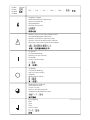
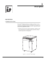
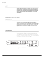
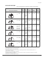
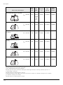
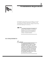
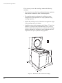
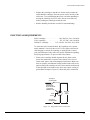
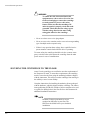
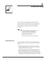
SJ-IM-8
Avanti® J-E Centrifuge
Instruction Manual
Symbol
Symbol
Symbole
Símbolo
Simbolo
Title
/
Titel
/
Titre
/
Titulo
/
Titolo
Dangerous voltage
Gefährliche elektrische Spannung
Courant haute tension
Voltaje peligroso
Pericolo: alta tensione
!
Attention, consult accompanying documents
Achtung! Begleitpapiere beachten!
Attention, consulter les documents joints
Atención, consulte los documentos adjuntos
Attenzione: consultare le informazioni allegate
On (power)
Ein (Netzverbindung)
Marche (mise sous tension)
Encendido
Acceso (sotto tensione)
Off (power)
Aus (Netzverbindung)
Arrêt (mise hors tension)
Apagado
Spento (fuori tensione)
Protective earth (ground)
Schutzleiteranschluß
Liaison à la terre
Puesta a tierra de protección
Collegamento di protezione a terra
Earth (ground)
Erde
Terre
Tierra
Scarica a terra
/
/
!
SAFETY NOTICE
This safety notice summarizes information basic to the safe operation of the equipment
described in this manual. The international symbol displayed above is a reminder that all
safety instructions should be read and understood before installation, operation, maintenance,
or repair of this centrifuge. When you see the symbol on other pages, pay special attention to
the safety information presented. Observance of safety precautions will also help to avoid
actions that could damage or adversely affect the performance of the centrifuge.
Safety During Installation and/or Maintenance
This centrifuge is designed to be installed by a Beckman Coulter Field Service representative.
Installation by anyone other than authorized Beckman Coulter personnel invalidates any
warranty covering the instrument.
Any servicing of this equipment that requires removal of any covers can expose parts which
involve the risk of electric shock or personal injury. Make sure that the power switch is off
and the centrifuge is disconnected from the main power source, and refer such servicing to
qualified personnel.
Use the anchoring system to secure the centrifuge in place. The anchoring system is
designed to reduce the possibility of injury or damage that could result from instrument
movement in the event of a major rotor mishap.
Do not replace any centrifuge components with parts not specified for use on this instrument.
Electrical Safety
To reduce the risk of electrical shock, this equipment uses a three-wire electrical cord and
plug to connect the centrifuge to earth-ground. To preserve this safety feature:
• Make sure that the matching wall outlet receptacle is properly wired and earth-grounded.
Check that the line voltage agrees with the voltage listed on the name-rating plate affixed
to the centrifuge.
• Never use a three-to-two wire plug adapter.
• Never use a two-wire extension cord or a two-wire non-grounding type of multiple-outlet
receptacle strip.
Do not place containers holding liquid on or near the chamber door. If they spill, liquid
may get into the centrifuge and damage electrical or mechanical components.
Safety Against Risk of Fire
Fuses protect certain electrical circuits within this instrument against overcurrent conditions.
For continued protection against the risk of fire, replace only with the same type and rating
specified.
This centrifuge is not designed for use with materials capable of developing flammable or
explosive vapors. Do not centrifuge such materials (such as chloroform or ethyl alcohol)
in this centrifuge nor handle or store them within the required 30-cm (1-ft) area
surrounding the centrifuge.
Mechanical Safety
For safe operation of the equipment, observe the following:
• Use only the rotors and accessories designed for use in this centrifuge.
• Do not exceed the maximum rated speed of the rotor in use.
• Do not lift or move the centrifuge while the rotor is spinning.
• NEVER attempt to slow or stop the rotor by hand.
• NEVER attempt to override the door interlock system while the rotor is spinning.
• In the event of a power failure, do not attempt to retrieve the sample from the centrifuge
for at least 1 hour. Then follow the instructions for sample recovery in Section 4,
TROUBLESHOOTING.
Chemical and Biological Safety
Normal operation may involve the use of solutions and test samples that are pathogenic,
toxic, or radioactive. Such materials should not be used in this centrifuge, however, unless
all necessary safety precautions are taken.
• Observe all cautionary information printed on the original solution containers prior to
their use.
• Handle body fluids with care because they can transmit disease. No known test offers
complete assurance that they are free of micro-organisms. Some of the most virulent—
Hepatitis (B and C) and HIV (I–V) viruses, atypical mycobacteria, and certain systemic
fungi—further emphasize the need for aerosol protection. Handle other infectious
samples according to good laboratory procedures and methods to prevent spread of
disease. Because spills may generate aerosols, observe proper safety precautions for
aerosol containment. Do not run toxic, pathogenic, or radioactive materials in this
centrifuge without taking appropriate safety precautions. Biosafe containment should
be used when Risk Group II materials (as identified in the World Health Organization
Laboratory Biosafety Manual) are handled; materials of a higher group require more
than one level of protection.
• Dispose of all waste solutions according to appropriate environmental health and safety
guidelines.
It is your responsibility to decontaminate the centrifuge and accessories before
requesting service by Beckman Coulter field service.
SJ-IM-8
August 2009
Avanti® J-E Centrifuge
Instruction Manual
© 2009 Beckman Coulter, Inc.
Contents
Page
INTRODUCTION
Certification . . . . . . . . . . . . . . . . . . . . . . . . . . . . . . . . . . . . . . . . . . . . vii
Scope of Manual. . . . . . . . . . . . . . . . . . . . . . . . . . . . . . . . . . . . . . . . . vii
Conventions . . . . . . . . . . . . . . . . . . . . . . . . . . . . . . . . . . . . . . . . . . . . . viii
Notes, Cautions, and Warnings . . . . . . . . . . . . . . . . . . . . . . . . . . . viii
Typographic Conventions . . . . . . . . . . . . . . . . . . . . . . . . . . . . . . . . ix
CFC-Free Centrifugation. . . . . . . . . . . . . . . . . . . . . . . . . . . . . . . . . . . . ix
Radio Interference . . . . . . . . . . . . . . . . . . . . . . . . . . . . . . . . . . . . . . . . . x
Canadian Regulations . . . . . . . . . . . . . . . . . . . . . . . . . . . . . . . . . . . x
Recycling Label . . . . . . . . . . . . . . . . . . . . . . . . . . . . . . . . . . . . . . . . . . . x
SECTION 1:
DESCRIPTION
Description . . . . . . . . . . . . . . . . . . . . . . . . . . . . . . . . . . . . . . . . . . . . . . 1-1
Centrifuge Function . . . . . . . . . . . . . . . . . . . . . . . . . . . . . . . . . . . . 1-1
Housing and Door . . . . . . . . . . . . . . . . . . . . . . . . . . . . . . . . . . . . . 1-2
Rotor Chamber. . . . . . . . . . . . . . . . . . . . . . . . . . . . . . . . . . . . . . . . 1-3
Vacuum . . . . . . . . . . . . . . . . . . . . . . . . . . . . . . . . . . . . . . . . . . . . . 1-3
Temperature Control . . . . . . . . . . . . . . . . . . . . . . . . . . . . . . . . . . . 1-3
Drive . . . . . . . . . . . . . . . . . . . . . . . . . . . . . . . . . . . . . . . . . . . . . . . 1-4
Control and Indicators . . . . . . . . . . . . . . . . . . . . . . . . . . . . . . . . . . . . . 1-4
Power Switch . . . . . . . . . . . . . . . . . . . . . . . . . . . . . . . . . . . . . . . . . 1-4
Control Panel . . . . . . . . . . . . . . . . . . . . . . . . . . . . . . . . . . . . . . . . . 1-4
Safety Features . . . . . . . . . . . . . . . . . . . . . . . . . . . . . . . . . . . . . . . . . . . 1-8
Door . . . . . . . . . . . . . . . . . . . . . . . . . . . . . . . . . . . . . . . . . . . . . . . . 1-8
Protective Ring . . . . . . . . . . . . . . . . . . . . . . . . . . . . . . . . . . . . . . . 1-8
Imbalance Detector . . . . . . . . . . . . . . . . . . . . . . . . . . . . . . . . . . . . 1-9
Overspeed and Rotor Identification System . . . . . . . . . . . . . . . . . 1-9
Name Rating Plate . . . . . . . . . . . . . . . . . . . . . . . . . . . . . . . . . . . . . . . . 1-9
Specifications . . . . . . . . . . . . . . . . . . . . . . . . . . . . . . . . . . . . . . . . . . . 1-10
Available Rotors. . . . . . . . . . . . . . . . . . . . . . . . . . . . . . . . . . . . . . . . . 1-11
SECTION 2:
PREINSTALLATION REQUIREMENTS
Space Requirements . . . . . . . . . . . . . . . . . . . . . . . . . . . . . . . . . . . . . . .
Electrical Requirements . . . . . . . . . . . . . . . . . . . . . . . . . . . . . . . . . . . .
Securing the Centrifuge to the Floor . . . . . . . . . . . . . . . . . . . . . . . . . .
Bio-Safety Level 3 Installation . . . . . . . . . . . . . . . . . . . . . . . . . . .
2-1
2-3
2-4
2-5
iii
Contents
Page
SECTION 3:
OPERATION
Summary of Run Procedures . . . . . . . . . . . . . . . . . . . . . . . . . . . . . . . . 3-2
Programmed Run . . . . . . . . . . . . . . . . . . . . . . . . . . . . . . . . . . . . . . 3-2
Manual Run . . . . . . . . . . . . . . . . . . . . . . . . . . . . . . . . . . . . . . . . . . 3-3
Preparation . . . . . . . . . . . . . . . . . . . . . . . . . . . . . . . . . . . . . . . . . . . . . . 3-3
Installing the Rotor . . . . . . . . . . . . . . . . . . . . . . . . . . . . . . . . . . . . 3-4
Manual Operation. . . . . . . . . . . . . . . . . . . . . . . . . . . . . . . . . . . . . . . . . 3-5
Selecting a Rotor . . . . . . . . . . . . . . . . . . . . . . . . . . . . . . . . . . . . . . 3-5
Entering Run Speed . . . . . . . . . . . . . . . . . . . . . . . . . . . . . . . . . . . . 3-6
Entering Run Time . . . . . . . . . . . . . . . . . . . . . . . . . . . . . . . . . . . . 3-6
Entering Run Temperature . . . . . . . . . . . . . . . . . . . . . . . . . . . . . . 3-7
Entering Acceleration and Deceleration Rates . . . . . . . . . . . . . . . 3-8
Starting a Run . . . . . . . . . . . . . . . . . . . . . . . . . . . . . . . . . . . . . . . . 3-9
Programmed Operation . . . . . . . . . . . . . . . . . . . . . . . . . . . . . . . . . . . . 3-9
Creating a New Program . . . . . . . . . . . . . . . . . . . . . . . . . . . . . . . 3-10
Starting a Programmed Run. . . . . . . . . . . . . . . . . . . . . . . . . . . . . 3-10
Recalling and Changing a Program . . . . . . . . . . . . . . . . . . . . . . . 3-11
SECTION 4:
TROUBLESHOOTING
User Messages . . . . . . . . . . . . . . . . . . . . . . . . . . . . . . . . . . . . . . . . . . . 4-1
Retrieving Your Sample in Case of Power Failure . . . . . . . . . . . . . . . 4-4
SECTION 5:
MAINTENANCE
Instrument Care . . . . . . . . . . . . . . . . . . . . . . . . . . . . . . . . . . . . . . . . . .
Maintenance. . . . . . . . . . . . . . . . . . . . . . . . . . . . . . . . . . . . . . . . . .
Cleaning. . . . . . . . . . . . . . . . . . . . . . . . . . . . . . . . . . . . . . . . . . . . .
Decontamination . . . . . . . . . . . . . . . . . . . . . . . . . . . . . . . . . . . . . .
Sterilization and Disinfection . . . . . . . . . . . . . . . . . . . . . . . . . . . .
Replacing the Air Filter . . . . . . . . . . . . . . . . . . . . . . . . . . . . . . . . .
Circuit Breaker and Fuses . . . . . . . . . . . . . . . . . . . . . . . . . . . . . . . . . .
Storage and Transportation . . . . . . . . . . . . . . . . . . . . . . . . . . . . . . . . .
Storage . . . . . . . . . . . . . . . . . . . . . . . . . . . . . . . . . . . . . . . . . . . . . .
Supply List . . . . . . . . . . . . . . . . . . . . . . . . . . . . . . . . . . . . . . . . . . . . . .
Replacement Parts . . . . . . . . . . . . . . . . . . . . . . . . . . . . . . . . . . . . .
Supplies . . . . . . . . . . . . . . . . . . . . . . . . . . . . . . . . . . . . . . . . . . . . .
Warranty
iv
5-1
5-2
5-2
5-3
5-3
5-4
5-5
5-5
5-5
5-6
5-6
5-6
Illustrations and Tables
Page
Figure 1-1.
The Avanti® J-E Centrifuge. . . . . . . . . . . . . . . . . . . . . . . . . . . . . . . . . 1-1
Figure 1-2.
Control Panel . . . . . . . . . . . . . . . . . . . . . . . . . . . . . . . . . . . . . . . . . . . . 1-4
Figure 2-1.
Dimensions of the Avanti® J-E Centrifuge . . . . . . . . . . . . . . . . . . . . . 2-2
Figure 2-2.
Single-Phase Power Connection . . . . . . . . . . . . . . . . . . . . . . . . . . . . . 2-3
Figure 4-1.
Manual Door Release . . . . . . . . . . . . . . . . . . . . . . . . . . . . . . . . . . . . . . 4-6
Figure 5-1.
Air Filter Replacement . . . . . . . . . . . . . . . . . . . . . . . . . . . . . . . . . . . . . 5-4
Table 4-1.
Diagnostic Message Chart . . . . . . . . . . . . . . . . . . . . . . . . . . . . . . . . . . 4-2
v
Introduction
CERTIFICATION
To ensure full system quality, Beckman Coulter Avanti® J-E centrifuges have been manufactured in a registered ISO 9001 or 13485
facility. They have been designed and tested to be compliant (when
used with Beckman Coulter rotors) with the laboratory equipment
requirements of applicable regulatory agencies. Declarations of
conformity and certificates of compliance are available at
www.beckmancoulter.com.
SCOPE OF MANUAL
This manual is designed to familiarize you with the Avanti® J-E
centrifuge, its functions, specifications, operation, and routine
operator care and maintenance. We recommend that you read this
entire manual, especially the SAFETY NOTICE and all safety-related
information, before operating the centrifuge or performing instrument
maintenance.
• Section 1 contains system specifications and a brief physical and
functional description of the centrifuge, including the operating
controls and indicators, and available rotors.
• Section 2 provides information about space and power requirements for installing and connecting the centrifuge.
• Section 3 contains centrifuge operating procedures.
• Section 4 lists possible malfunctions, together with probable
causes and suggested corrective actions.
• Section 5 contains procedures for routine operator care and maintenance, as well as a brief list of supplies and replacement parts.
vii
Introduction
➠
NOTE
If the centrifuge is used in a manner other
than specified in this manual, the safety and
performance of this equipment could be
impaired. Further, the use of any equipment
other than that recommended by Beckman
Coulter has not been evaluated for safety. Use of
any equipment not specifically recommended in
this manual and/or the applicable rotor manual is
the sole responsibility of the user.
CONVENTIONS
Certain symbols are used in this manual to call out safety-related and
other important information. These international symbols may also be
displayed on the centrifuge and are reproduced and described below
and on the inside of the front cover.
NOTES, CAUTIONS, AND WARNINGS
➠
!
viii
NOTE
Used to call attention to important information
that should be followed during installation, use,
or servicing of this equipment.
CAUTION
Used to indicate a potentially hazardous situation which, if not avoided, may result in minor or
moderate injury and/or mechanical damage. It
is also used to alert against unsafe practices.
Introduction
!
WARNING
Used whenever an action or condition may
potentially cause personal injury or loss of
life. Mechanical damage may also result.
WARNING
Indicates high voltage or risk of electric
shock. Refer servicing of all areas displaying
either symbol to service personnel.
TYPOGRAPHIC CONVENTIONS
Certain typographic conventions are used throughout this manual to
distinguish names of user interface components, such as keys.
• Keynames (for example, [START] or [PROGRAM]) appear in capital
letters within brackets.
CFC-FREE CENTRIFUGATION
CFC
To ensure minimal environmental impact, no CFCs are used in the
manufacture or operation of Avanti J-E centrifuges.
ix
Introduction
RADIO INTERFERENCE
This equipment has been tested and found to comply with the limits
for a Class A digital device, pursuant to Part 15 of FCC Rules. These
limits are designed to provide reasonable protection against harmful
interference when the equipment is operated in a commercial environment. This equipment generates, uses, and can radiate radio
frequency energy and, if not installed and used in accordance with
this instruction manual, may cause interference to radio communications. Operation of this equipment in a residential area is likely to
cause interference, in which case the user will be required to correct
the interference at his own expense.
CANADIAN REGULATIONS
This equipment does not exceed the Class A limits for radio noise
emissions from digital apparatus as set out in the radio interference
regulations of the Canadian Department of Communications.
Le présent appareil numérique n’émet pas de bruits radioélectriques
dépassant les limites applicables aux appareils numériques de Classe
A prescrites dans le reglement sur le brouillage radioelectrique édicté
par le Ministère des Communications du Canada.
RECYCLING LABEL
This symbol is required in accordance with the Waste Electrical and
Electronic Equipment (WEEE) Directive of the European Union. The
presence of this marking on the product indicates:
A28219-AA
Note: On the instrument, the
triangle background is yellow
rather than gray.
1) the device was put on the European market after August 13, 2005
and
2) the device is not to be disposed via the municipal waste collection
system of any member state of the European Union.
It is very important that customers understand and follow all laws
regarding the proper decontamination and safe disposal of electrical
equipment. For Beckman Coulter products bearing this label please
contact your dealer or local Beckman Coulter office for details on the
take back program that will facilitate the proper collection, treatment,
recovery, recycling and safe disposal of the device.
x
1
Description
DESCRIPTION
CENTRIFUGE FUNCTION
The Avanti® J-E high-performance centrifuge (see Figure 1-1) is a
refrigerated centrifuge that generates centrifugal forces required for a
wide variety of applications. Together with the compatible Beckman
Coulter rotors, applications include:
• Routine processing such as sample preparations, pelleting, extractions, purifications, concentrations, phase separations, and spin
column and spin filter centrifugations.
Figure 1-1. The Avanti® J-E Centrifuge
1-1
Description
• Rapid sedimentation of protein precipitates, large particles, and
cell debris.
• Preparation of subcellular organelles such as mitochondria, nuclei,
chloroplasts, and crude microsomes.
• Separation of blood cells and cellular components.
• Gradient separation, for example, Ficoll-Hypaque1 and Percoll.1
The Avanti J-E is microprocessor-controlled, providing interactive
operation. The instrument design features a brushless switchedreluctance drive motor,2 a temperature control system with automatic
temperature compensation unique for each compatible rotor, and
selectable acceleration and deceleration rates.
Manual and programmed operation are available.
• In manual operation, you enter the individual run parameters
before beginning each run.
• In programmed operation, you can duplicate runs quickly and
accurately by selecting one of nine programs previously entered
into the program memory.
User messages and/or audible signals are provided to alert you to
conditions that may need attention.
HOUSING AND DOOR
The instrument housing is made of steel and molded structural foam.
The door and structural-foam cover panels are finished with polyurethane enamel.
The steel and structural foam door is hinged at the back, providing
clearance for loading and unloading of the centrifuge. In the event of
a power failure, the door can be manually unlocked for sample
recovery (see Section 4, TROUBLESHOOTING).
1
2
1-2
Registered trademarks of Pharmacia AB.
Manufactured under license from Switched Reluctance Drives Limited, Harrogate, U.K.
Description
ROTOR CHAMBER
The rotor chamber is made of stainless steel to resist corrosion.
A rubber gasket around the chamber opening ensures sealing.
(Instrument gaskets have not been qualified as bioseals for aerosol
containment.)
VACUUM
The friction reduction system (FRS) uses a mechanical rotary vane
vacuum pump to reduce chamber pressure to approximately one-half
atmosphere. The pump turns on when the run is started, before rotor
friction reaches a high level. Vacuum in the chamber is vented automatically during rotor deceleration.
TEMPERATURE CONTROL
The temperature control system cools by circulation of a non-CFCbased refrigerant. The system is activated when the centrifuge power
is on and when the door is closed and latched.
A thermistor in the rotor chamber continuously monitors the chamber
temperature. The system calculates the chamber temperature required
to maintain the set rotor temperature, ±2°C. Although the chamber
temperature fluctuates during operation, the rotor’s large mass keeps
the sample temperature substantially constant. At the end of a run,
the system continues controlling the temperature for 30 minutes to
prevent freezing or overheating of the sample.
➠
NOTE
The system will always shut down using
maximum brake if the temperature goes
above 50°C.
1-3
Description
DRIVE
The drive shaft is belt driven by a brushless, high-torque, switchedreluctance motor. The instrument’s resilient suspension minimizes
disturbance of the sample during acceleration and deceleration, and
reduces damage to the drive shaft if an imbalance occurs during
centrifugation.
CONTROLS AND INDICATORS
POWER SWITCH
The power switch, located on the right panel of the centrifuge,
controls electrical power to the centrifuge. It is also a circuit breaker
that will trip to cut off power in the event of a power overload. The
power switch must be turned on before the chamber door can be
opened.
CONTROL PANEL
The control panel (see Figure 1-2) is mounted at an angle on the
centrifuge front for easy visibility and access. It is used to enter run
parameters via function keys and a keypad, and to display run parameters, program information, and user messages.
Figure 1-2. Control Panel
1-4
Description
Digital Displays
The displays provide run information, user messages, and
diagnostics.
• During a run, they show the actual (real-time) operating
conditions.
• When the run parameters are being entered, they show the set
values selected. Set values can be recalled during operation by
pressing [SHOW SET]. After 5 seconds, the displays return to actual
conditions.
(SPEED)
Indicates rotor speed in revolutions per minute (rpm) or in relative
centrifugal field, a term describing the ratio of the centrifugal acceleration at a specified radius and speed to the standard acceleration of
gravity (RCF × g).
(TIME)
• In a timed run, indicates the remaining run time in hours and
minutes. The time display begins counting down when [START]
is pressed and continues counting down to 0, when deceleration
begins. The run automatically ends when the set time reaches zero
(a tone sounds when the rotor stops spinning). If a malfunction
shuts down the centrifuge during a run, the time counting stops and
the time remaining when the run stopped remains in the display.
By comparing this time with the original set time, you
can determine when the run ended.
• In a hold run, indicates the time elapsed since [START] was pressed.
After 99 hours and 59 minutes the timer resets to 0 and continues
counting elapsed time.
(TEMPERATURE)
Indicates rotor temperature in degrees C at thermoequilibrium. The
displayed temperature is within ±2 degrees of the set temperature
(after equilibration).
(ROTOR)
Displays the name of the installed rotor.
(ACCEL)
When the [ACCEL] key is pressed, an acceleration rate (1 = MAX,
2 = SLOW) can be entered. If no number is entered, the instrument
accelerates at the rate set for the previous run.
(DECEL)
When the [DECEL] key is pressed, a number representing the selected
deceleration rate (1 = MAX, 2 = SLOW, 3 = OFF) can be entered. If
no number is entered, the instrument decelerates at the rate set for the
previous run.
1-5
Description
(PROGRAM)
• During setup—when the [PROGRAM] key is pressed a program
number (one of nine possible) can be entered.
• During centrifugation—the number of the program being run is
displayed.
Run-Parameter Keys
Run-parameter keys are used to enter specific run information as
follows.
Pressed to display scrolling list of compatible rotors and rotor entry
codes. Can be pressed repeatedly to scroll more quickly through the
rotor list.
If the display shows speed in rpm, the key is pressed once to enter run
speed (using the keypad) in rpm (revolutions per minute); pressed
twice to enter run speed in RCF (relative centrifugal field). If the
display shows speed in RCF, the key is pressed once to enter speed
in RCF or twice to enter speed in rpm.
Pressed to enter run time using the keypad. When [TIME] is pressed
twice, HOLD mode is selected. (Pressing it again reverts to timeentry mode.)
• Timed run—Run time up to 99 hours and 59 minutes can be set. If
more than 59 minutes are entered in the minutes field, the system
automatically converts the entry to hours and minutes. Deceleration begins when the set time counts down to zero.
• Continuous run (hold)—For runs of unspecified lengths, hold
mode is used. When 99 hours, 59 minutes is reached, the system
resets to 0 and continues counting. A hold run continues until the
[STOP] key is pressed.
Pressed to enter run temperature (using the keypad), from –10 to
+40°C. If a new temperature is not entered, the centrifuge uses the
temperature set for the previous run.
1-6
Description
The centrifuge has two acceleration profiles: MAX—maximum
acceleration from 0 rpm to set speed, or SLOW—slow acceleration
from 0 to 500 rpm, followed by maximum acceleration to set speed.
The [ACCEL] key is used to select the maximum acceleration or slow
acceleration, provided to maintain optimum separation.
The centrifuge has three deceleration profiles: MAX—full dynamic
braking to 0 rpm; SLOW—brake to 500 rpm followed by reduced
braking to a gentle stop; OFF (coast from set speed to stop). The
[DECEL] key is used to select the deceleration rate provided to maintain optimum separation.
A toggle switch used to enter into and exit out of the program mode
to create or recall programs. When the key is pressed, the program
number can be selected using the keypad.
Saves the program in memory after program run parameters have
been entered.
The keypad is used to enter numerical run parameters, to enter or
recall a program number, and to select acceleration and/or deceleration rates. In addition to keys 0 through 9, the keypad includes plus or
minus/decimal key and a [CE] (clear entry) key.
The [± .] key is used to enter a temperature setting below 0°C (for
example, –2°C), or to enter a decimal point in a rotor entry code,
depending on the parameter key selected.
The [CE] (clear entry) key clears any parameter on the display.
Pressing [CE] will also clear some diagnostic messages. If a
diagnostic message does not clear when [CE] is pressed, see Section 4,
TROUBLESHOOTING.
The [ENTER] key can be pressed to save parameter inputs to system
memory during manual run setup, and to start the centrifuge ([ENTER],
then [START] must be pressed to start the centrifuge).
1-7
Description
Pressed during a run to display set values for 5 seconds.
Pressing [ENTER], then [START] begins the run. ([START] must be
pressed within 5 seconds of pressing [ENTER].) This key combination
can also be used to abort a deceleration process and restart the
centrifuge.
Can be pressed at any time while the rotor is spinning to terminate
a run. The centrifuge decelerates to a complete stop according to the
deceleration setting. The green light next to the key flashes while the
rotor decelerates. An audio indicator sounds when the rotor comes to
a complete stop.
Locks and unlocks the door. (The instrument will not accept the open
command if the rotor is spinning.)
SAFETY FEATURES
The Avanti J-E centrifuge has been designed and tested to operate
safely indoors at altitudes up to 2 000 m (6 562 ft). Safety features
include the following.
DOOR
The steel and structural foam door has an electromechanical doorlocking mechanism, with dual latches, to prevent operator contact
with a spinning rotor. When the door is closed and [DOOR] is pressed,
the latches automatically engage. (Door LED will come on.) It can be
unlocked only by pressing [DOOR], and opened only when the power
is on and the rotor is at rest. If there is a power failure, the door lock
can be manually tripped for sample recovery (see Section 4,
TROUBLESHOOTING).
1-8
Description
PROTECTIVE RING
A structural steel ring surrounding the rotor chamber provides full
operator protection.
IMBALANCE DETECTOR
An imbalance detector monitors the rotor during the run, causing
automatic shutdown if rotor loads are severely out of balance. At
low speeds, an incorrectly loaded rotor can cause an imbalance.
Rotor instability can also occur if the instrument is moved, or if it is
not resting level on the floor (see Section 4, TROUBLESHOOTING).
OVERSPEED AND ROTOR IDENTIFICATION SYSTEM
A rotor identification system prevents the installed rotor from running
above its maximum rated speed. During acceleration the microprocessor checks the magnetic rotor identification. If the system
identifies a rotor different than the one entered by the user, and the
set speed is above the maximum for the identified rotor, the system
will reduce the set speed to the maximum for the installed rotor.
A second check, based on rotor physical properties, is performed
during acceleration. Speed is limited to the maximum safe speed of
the identified rotor group.
➠
NOTE
Some rotors manufactured before January, 2002,
may not have magnets installed. Based on the
rotor property grouping, these rotors may be
limited to a lower speed than the rated speed.
NAME RATING PLATE
A name rating plate is affixed to the rear of the instrument. Always
mention the serial number and model number when contacting
Beckman Coulter regarding your Avanti J-E centrifuge.
1-9
Description
SPECIFICATIONS
Only values with tolerances or limits are guaranteed data. Values
without tolerances are informative data, without guarantee.
Speed
Set speed . . . . . . . . . . . . . . . . 300 to 21 000 rpm in 10-rpm increments
Speed control . . . . . . . . . . . . . actual rotor speed, ±50 rpm of set speed
Speed display . . . . . . . . . . . . . actual rotor speed in 10-rpm increments
or actual rcf × g
Time
Set time . . . . . . . . . . . . . . . . . . . . . . . . . . . . . . to 99 hours 59 minutes
or continuous (hold)
Time display
Timed run . . . . . . . . . . . . . . . . . . . . . indicates run time remaining
Hold run . . . . . . . . . . . . . . . . . . . . . . . . . . . . displays elapsed time
Temperature
Set temperature . . . . . . . . . . . . . . . . . . –10 to +40°C in 1° increments
Temperature control (after equilibration). . . . . ±2°C of set temperature
Ambient temperature range . . . . . . . . . . . . . . . . . . . . . . . . . 15 to 35°C
Humidity restrictions. . . . . . . . . . . . . . . . . . . . . . . . <95% (noncondensing)
Vacuum . . . . . . . . . . . . . . . . . . . . . . . . . . . . . . . . . . . . . . . . . 1/2 atmosphere
Acceleration . . . . . . . . . two profiles—MAX (full acceleration to set speed)
and SLOW
Deceleration . . . . . . . . . . three profiles—MAX, SLOW, and OFF (coast)
Dimensions
Width . . . . . . . . . . . . . . . . . . . . . . . . . . . . . . . . . . . . . . 63.5 cm (25 in.)
Depth . . . . . . . . . . . . . . . . . . . . . . . . . . . . . . . . . . . . . 80.0 cm (31.5 in.)
Height (door closed). . . . . . . . . . . . . . . . . . . . . . . . . . . 91.4 cm (36 in.)
Height (door open) . . . . . . . . . . . . . . . . . . . . . . . . . . . 152.4 cm (60 in.)
Weight . . . . . . . . . . . . . . . . . . . . . . . . . . . . . . . . . . . . . . . . 267.4 kg (589 lb)
Ventilation clearances
Sides . . . . . . . . . . . . . . . . . . . . . . . . . . . . . . . . . . . . . . . . 7.6 cm (3.0 in.)
Rear . . . . . . . . . . . . . . . . . . . . . . . . . . . . . . . . . . . . . . 16.0 cm (6.25 in.)
Finishes
Control panel . . . . . . . . . . . . . . . . . . . . . . . . . . . . . . . silicone elastomer
Top surface . . . . . . . . . . . . . . . . . . . . . . . . . . . . . . . . . . . . urethane paint
Other surfaces . . . . . . . . . . . . . . . . . . . . . . . . . . acrylic baking enamel
Electrical requirements
208/240-V instrument . . . . . . . . 187–229/216–264 VAC, 24 A, 60 Hz
230-V instrument . . . . . . . . . . . . . . . . . . . . 207–253 VAC, 24 A, 50 Hz
200-V instrument . . . . . . . . . . . . . . . . . . . . 180–220 VAC, 24 A, 50 Hz
Electrical supply . . . . . . . . . . . . . . . . . . . . . . . . . . . . . . . . . . . . . . . . . .Class I
Maximum heat dissipation into room under
steady-state conditions . . . . . . . . . . . . . . . . . . . . . . . 6 900 Btu/hr (2 kW)
Noise level 0.91 m (3 ft) in front of centrifuge at 21 000 rpm . . . . <64 dBa
Installation (overvoltage) category . . . . . . . . . . . . . . . . . . . . . . . . . . . . . . . II
Pollution degree. . . . . . . . . . . . . . . . . . . . . . . . . . . . . . . . . . . . . . . . . . . . . 2*
__________
* Normally only nonconductive pollution occurs; occasionally, however, a temporary conductivity caused by condensation must be expected.
1-10
Description
AVAILABLE ROTORS
Refer to the applicable rotor manual for complete rotor descriptions.
Rotor Profile and Description
Rotor
Entry
Code
Max
RPM a
Max RCF
(× g)
Max
Capacity
Rotor
Manual
Number
25.5
21 000b
53 300
8 × 50 mL
J-TB-056
50 400
18 × 10 mL
J-TB-002
20 000
51 500
32 × 15 mL
J-TB-022
(17 000
@ 2°C)c
43 900
20 000
48 400
8 × 50 mL
J-TB-003
37 800
10 × 100 mL
J-TB-035
39 800
14 × 50 mL
J-TB-017
JA-25.50 Fixed Angle, 34° (8 place)
rmax = 108 mm
(18 000
@ 2°C)c
JA-21 Fixed Angle, 40° (18 place)
rmax = 102 mm
21
21 000
(18 000
@ 2°C)c
JA-20.1 Fixed Angle, 23° (32 place)
rmax = 115 mm
(outer row)
20.1
rmax = 98 mm
(inner row)
JA-20 Fixed Angle, 34° (8 place)
rmax = 108 mm
20
(17 000
@ 2°C)c
JA-18 Fixed Angle, 23° (10 place)
rmax = 132 mm
18
16 000d
(14 000
@ 2°C)c
JA-17 Fixed Angle, 25° (6 place)
rmax = 132 mm
17
17 000e
(15 000
@ 2°C)c
a
Maximum speeds are based on a solution density of 1.2 g/mL in all rotors.
b
Maximum speed for the rotor in the Avanti® J-E centrifuge.
c
At 35°C ambient temperature and 95 percent humidity.
d
Maximum speed in the Avanti J-E for the rotor with magnets; without magnets maximum is 14 000 rpm. (Maximum speed at 2°C in
a 50-Hz centrifuge is 14 000 rpm.)
e
Maximum speed for rotor without magnets is 13 000 rpm.
f
Temperature performance for the F14BCI-14x50cy rotor in the Avanti J-E is as follows: 12°C minimum at 14 000 rpm (at 35°C ambient);
4°C minimum at 13 000 rpm (35°C ambient).
g
Maximum speed for rotor without magnets is 6 300 rpm.
1-11
Description
Rotor Profile and Description
Rotor
Entry
Code
Max
RPM a
Max RCF
(× g)
Max
Capacity
Rotor
Manual
Number
16.25
16 000d
38 400
6 × 250 mL
J-TB-072
JLA-16.250 Fixed Angle, 25° (6 place)
rmax = 134 mm
(14 000
@
2°C)c
JA-14 Fixed Angle, 25° (6 place)
F14BCI-14x50cy Fixed Angle, 34°
(14 place)f
F14BCI-6x250y Fixed Angle, 23°
(6 place)
rmax = 137 mm
14
14 000
30 100
6 × 250 mL
J-TB-004
rmax = 153 mm
50
14 000
33 500
14 × 50 mL
—
rmax = 137 mm
250
14 000
30 000
6 × 250 mL
—
rmax = 144 mm
12
12 000
23 200
12 × 50 mL
J-TB-051
rmax = 158 mm
10
10 000g
17 700
6 × 500 mL
J-TB-006
JA-12 Fixed Angle, 35° (12 place)
JA-10 Fixed Angle, 25° (6 place)
a
Maximum speeds are based on a solution density of 1.2 g/mL in all rotors.
b
Maximum speed for the rotor in the Avanti® J-E centrifuge.
c
At 35°C ambient temperature and 95 percent humidity.
d
Maximum speed in the Avanti J-E for the rotor with magnets; without magnets maximum is 14 000 rpm. (Maximum speed at 2°C in
a 50-Hz centrifuge is 14 000 rpm.)
e
Maximum speed for rotor without magnets is 13 000 rpm.
f
Temperature performance for the F14BCI-14x50cy rotor in the Avanti J-E is as follows: 12°C minimum at 14 000 rpm (at 35°C ambient);
4°C minimum at 13 000 rpm (35°C ambient).
g
Maximum speed for rotor without magnets is 6 300 rpm.
1-12
Description
Rotor
Entry
Code
Max
RPM a
Max
RCF
(× g)
Max
Capacity
Rotor
Manual
Number
rmax = 166 mm
10.5
10 000g
18 600
6 × 500 mL
J-TB-048
rmax = 158 mm
500
10 000
17 696
6 × 500 mL
—
rmax = 185 mm
9.1
6 300 b
8 230
4 × 1000 mL
J-TB-073
rmax = 140 mm
13
13 000
26 500
6 × 50 mL
J-TB-036
6 130
4 × 500 mL
24 microplates
8 deep-well plates
4 square-well plates
J-TB-089
Rotor Profile and Description
JLA-10.500 Fixed Angle, 20° (6 place)
F10BCI-6x500y Fixed Angle, 23°
(6 place)
JLA-9.1000 Fixed Angle, 20° (4 place)
JS-13.1 Swinging Bucket (6 place)
(12 000
@
2°C)c
JS-5.3 Swinging Bucket (4 place)
rmax = 194.8 mm
5.3
5 300
a
Maximum speeds are based on a solution density of 1.2 g/mL in all rotors.
b
Maximum speed for the rotor in the Avanti® J-E centrifuge.
c
At 35°C ambient temperature and 95 percent humidity.
d
Maximum speed in the Avanti J-E for the rotor with magnets; without magnets maximum is 14 000 rpm. (Maximum speed at 2°C in
a 50-Hz centrifuge is 14 000 rpm.)
e
Maximum speed for rotor without magnets is 13 000 rpm.
f
Temperature performance for the F14BCI-14x50cy rotor in the Avanti J-E is as follows: 12°C minimum at 14 000 rpm (at 35°C ambient);
4°C minimum at 13 000 rpm (35°C ambient).
g
Maximum speed for rotor without magnets is 6 300 rpm.
1-13
2
Preinstallation Requirements
Preinstallation requirements have been provided for your Avanti®
J-E centrifuge. The following information is included in case the
instrument must be relocated. (After the centrifuge is moved it must
be leveled by adjusting the two front feet.)
➠
NOTE
This centrifuge is designed to be installed by a
Beckman Coulter Field Service representative.
Installation by anyone other than authorized
Beckman Coulter personnel invalidates any
warranty covering the instrument.
SPACE REQUIREMENTS
!
WARNING
Do not place the centrifuge near areas
containing flammable reagents or combustible fluids. Vapors from these materials
could enter the centrifuge air system and be
ignited by the motor. Maintain a 30-cm (1-ft)
clearance area around the centrifuge while
it is running. No persons or any hazardous
materials should be within this area while
the centrifuge is operating except to change
operating controls, if required.
2-1
Preinstallation Requirements
If it is necessary to move the centrifuge, maintain the following
conditions.
• Select a location away from heat-producing laboratory equipment,
with sufficient ventilation to allow for heat dissipation.
• The centrifuge must have adequate air ventilation to ensure
compliance to local requirements for vapors produced during
centrifuge operation.
• Position the centrifuge on a level floor that can support the weight
of the centrifuge and resist vibration.
• In addition to space for the instrument itself, allow a 7.7-cm (3-in.)
clearance on each side of the instrument and a 16-cm (6.25-in.)
clearance behind the instrument for air circulation. The centrifuge
must have adequate air ventilation to ensure compliance to local
requirements for vapors produced during operation.
in.
cm
60.0
152.4
34.0
86.4
6.25
16.0
3.0
7.7
31.5
80.0
25.0
63.5
3.0
7.7
Figure 2-1. Dimensions of the Avanti® J-E Centrifuge
2-2
Preinstallation Requirements
• Position the centrifuge so that the air diverter nearly touches the
wall behind the centrifuge. Place the power cord to one side of the
air diverter. To avoid damaging the power cord when installing or
moving the centrifuge, be sure to move the cord out of the way
before pushing the centrifuge toward the wall.
• Relative humidity should not exceed 95% (noncondensing).
ELECTRICAL REQUIREMENTS
200-V centrifuge . . . . . . . . . . . . . . . . 180–220 VAC, 24 A, 50/60 Hz
230-V centrifuge . . . . . . . . . . . . . . . . 207–253 VAC, 24A, 50/60 Hz
208/240-V centrifuge. . . . . . . . 187–229/216–264 VAC, 24A, 50 Hz
To reduce the risk of electrical shock, this centrifuge uses a permanently attached 1.8-m (6-ft) three-wire UL/CSA approved electrical
cord and plug to connect the centrifuge to earth-ground. (Contact
your local Beckman Coulter office for specific information regarding
local plug requirements.) To preserve this safety feature:
• Power to the centrifuge should originate directly from a main
power line transformer at a power source known to be clear of
erratic loads, spikes, and electromagnetic interference. Make sure
there are properly rated thermal circuit breakers at the wall service
panel to protect the centrifuge circuit. If fuses must be used instead
of the specified circuit breakers, the fuses may require a rating of
greater than 30 amperes. Figure 2-2 shows the power connection.
30-ampere
Circuit Breaker
Wall Outlet:
Hubbell 9330,
Bryant 96-30-FR,
or Equivalent
(NEMA 6-30 R)
Earth
Ground
Measured
Line
Voltage
30-ampere
Circuit Breaker
Figure 2-2. Single-Phase Power Connection
2-3
Preinstallation Requirements
!
WARNING
To reduce the risk of electrical shock, this
equipment uses a three-wire or five-wire electrical cord and plug to connect the centrifuge
to earth-ground. To preserve this safety
feature, make sure that the matching wall
outlet receptacle is properly wired and earthgrounded. Check that the line voltage agrees
with the voltage listed on the name rating
rating plate affixed to the centrifuge.
• Never use a three-to-two wire plug adapter.
• Never use a two-wire extension cord or a two-wire non-grounding
type of multiple-outlet receptacle strip.
• If there is any question about voltage, have a qualified service
person measure it under load while the drive is operating.
To ensure safety the centrifuge should be wired to a remote emergency switch in order to disconnect the centrifuge from the main
power source in case of a malfunction.
SECURING THE CENTRIFUGE TO THE FLOOR
Avanti J series centrifuges are certified to meet the requirements of
the European CE mark. To meet these requirements, the centrifuge
must be secured to the floor using the anchoring hardware shipped
with the instrument. This will prevent the centrifuge from moving in
the unlikely event of a rotor mishap.
Complete instructions for installing the anchoring kit are packaged
with the hardware, which is shipped with the centrifuge. The instructions (publication SJ-TB-003) include a full-size template to be used
as a guide for drilling holes in the floor. Refer to this document for
additional installation instructions.
➠
2-4
NOTE
Beckman Coulter representatives are not
equipped to drill holes in your floor. The
holes must be drilled before your scheduled
installation.
Preinstallation Requirements
BIO-SAFETY LEVEL 3 INSTALLATION
For laboratories with epoxy aggregate floors, such as BSL-3 labs, a
non-invasive installation kit (PN 393830) is available. The kit which
consists of an adhesive-backed mounting plate, is CSA certified for
use on epoxy aggregate floors only.
2-5
3
Operation
This section contains manual and programmed operating procedures.
A summary is provided at the start of this section. If you are an experienced user of this centrifuge, you can turn to the summary for a
quick review of operating steps.
!
WARNING
Normal operation may involve the use of solutions and test samples that are pathogenic,
toxic, or radioactive. Handle body fluids
with care because they can transmit disease.
No known test offers complete assurance that
they are free of micro-organisms. Some of the
most virulent—Hepatitis (B and C) and HIV
(I–V) viruses, atypical mycobacteria, and
certain systemic fungi—further emphasize
the need for aerosol protection. Handle other
infectious samples according to good laboratory procedures and methods to prevent
spread of disease. Because spills may generate
aerosols, observe proper safety precautions
for aerosol containment. Do not run toxic,
pathogenic, or radioactive materials in this
centrifuge without taking appropriate safety
precautions. Biosafe containment should be
used when Risk Group II materials (as
identified in the World Health Organization
Laboratory Biosafety Manual) are handled;
materials of a higher group require more
than one level of protection.
3-1
Operation
!
WARNING
Do not use the centrifuge in the vicinity of
flammable liquids or vapors, and do not run
such materials in the instrument. Do not lean
on the instrument or place items on it while it
is operating.
SUMMARY OF RUN PROCEDURES
For runs at other than room temperature, refrigerate or warm
the rotor beforehand for fast equilibration.
PROGRAMMED RUN
1
POWER
Turn the power switch on (I).
2
[DOOR]
Press [DOOR] to unlock the chamber door; lift the door open.
3
3-2
Install the rotor according to the applicable rotor manual, then
close the chamber door and press [DOOR].
4
[PROGRAM]
Press [PROGRAM], use the keypad to enter the required program
number, then press [ENTER]. Press [SHOW SET] to display program
parameters.
5
[ENTER]
[START]
Check that all parameters are correct and that the door is closed.
Press [ENTER], then press [START] (within 5 seconds).
6
[STOP]
Wait for the run to end, or end the run by pressing [STOP].
7
[DOOR]
When the rotor stops (a tone sounds), press [DOOR] to unlock the
chamber door; lift the door open to remove the rotor.
Operation
MANUAL RUN
1
POWER
Turn the power switch on (I).
2
[DOOR]
Press [DOOR] to unlock the chamber door; lift the door open.
3
Install the rotor according to the applicable rotor manual, then
close the chamber door and press [DOOR].
4
[ROTOR]
Press [ROTOR], then use the keypad to enter the rotor entry code.
5
[RPM/RCF]
Press [RPM/RCF], then use the keypad to enter the run speed (300 to
21 000 rpm). Press [RPM/RCF] a second time to enter speed in RCF.
6
[TIME]
Press [TIME], then use the keypad to enter the run time (to 99 hrs,
59 minutes); or press [TIME] twice for a hold (continuous) run.
7
[TEMP °C]
Press [TEMP °C], then use the keypad to enter the required run
temperature (–10 to +40°C).
8
[ACCEL]
Press [ACCEL], then use the keypad to enter the selected acceleration rate number, 1 or 2.
9
[DECEL]
Press [DECEL], then use the keypad to enter the selected deceleration rate number, 1, 2, or 3.
10
[ENTER]
[START]
Check that all parameters are correct and that the door is closed.
Press [ENTER], then press [START] (within 5 seconds).
11
[STOP]
Wait for the set time to count down to zero, or end the run by
pressing [STOP].
12
[DOOR]
When the rotor stops (a tone sounds), press [DOOR] to unlock the
chamber door; lift the door open to remove the rotor or sample.
PREPARATION
Prepare the rotor for centrifugation as described in the applicable
rotor manual. For runs at other than room temperature, refrigerate
or warm the rotor beforehand for fast equilibration.
3-3
Operation
INSTALLING THE ROTOR
The power must be turned on before you can unlock and open the
chamber door. (To end a run for any reason, do not turn the power
switch off; press [STOP] instead.)
Action
Result
1. Turn the power switch on.
Indicator lights on the control panel light up.
2. Press [DOOR] to unlock
the door.
The instrument will accept this command only when the rotor is
at rest.
3. Lift the door up to open.
!
4. Install the rotor according
to directions in the rotor
manual. Ensure that the rotor
is seated on the drive hub.
Avoid bumping the control
panel keys during rotor
installation or removal.
(If you bump the control
panel and an L1 diagnostic
appears, press [CE] to
clear the message.)
3-4
CAUTION
Rotors used in Avanti J series centrifuges must
have drive pins in the rotor drive hole. These
drive pins engage with the centrifuge drive hub
to ensure that the rotor does not slip during
acceleration. Some Beckman Coulter rotors
were originally manufactured without drive pins
because these rotors did not need pins to run in
older model centrifuges. To check for drive pins,
hold the rotor up or turn it on its side and look
into the drive hole. If you do not see at least two
metal pins near the top of the hole, do not use
the rotor in the Avanti J-E.
Operation
Action
Result
5. Close the chamber door and
press [DOOR]. (To keep the
chamber clean and dry, leave
the door closed whenever
possible.)
The door latches. When the latches engage, the LED next to the
[DOOR] key lights.
MANUAL OPERATION
• When a run-parameter key ([ROTOR], [RPM/RCF], [TIME], [TEMP],
[ACCEL], or [DECEL]) is pressed, a parameter can be entered or
changed. Entry is completed when [ENTER] or another function
key is pressed.
• To change an entry before you’ve pressed [ENTER] or another
parameter key, press [CE] and enter a different value. To change
an entry after you’ve pressed [ENTER], press the run-parameter
key again.
• If an unacceptable value is entered, the valid range for that parameter is displayed in the message line. Enter the correct value.
SELECTING A ROTOR
Action
Result
1. Press [ROTOR].
A list of rotors, with rotor entry codes, scrolls across the display.
2. Use the keypad to select a
rotor by entry code number.
➠
NOTE
An alternate method of selecting a rotor is to
press [ROTOR] repeatedly; the rotor number
changes each time the key is pressed. When the
rotor you are using is displayed, press [ENTER].
3. Press the next run-parameter
key or press [ENTER].
3-5
Operation
ENTERING RUN SPEED
Enter a run speed up to the maximum speed of the rotor in use
(21 000 rpm maximum). Or, enter a relative centrifugal field (RCF)
value up to the maximum achievable RCF of the rotor.
Action
Result
1. Press [RPM/RCF] once to enter
speed in RPM or twice to
enter speed in RCF.
Allowed speed for the selected rotor is displayed.
2. Use the keypad to enter
required speed.
Entered speed appears on the speed display. (If the entered speed is
higher than the rated speed of the installed rotor, a message showing
the valid speed range will be displayed. Press [CE] and enter an
acceptable value.)
3. Press the next run-parameter
key or [ENTER].
You can change the set speed at any time by repeating steps 1
through 3. The rotor will accelerate or decelerate to the new speed.
➠
NOTE
During acceleration, the instrument identifies
the rotor and checks its maximum allowable
speed. If set speed is greater than the rotor
group’s maximum allowable speed, the rotor
will decelerate to its rated speed, and an error
message will be displayed. Refer to Section 4,
TROUBLESHOOTING.
ENTERING RUN TIME
Run time can be set for up to 99 hours and 59 minutes or for a hold
(continuous) run. The time display begins counting down when the
rotor starts to spin. For a timed run, the run automatically terminates
when the set time reaches zero; a tone sounds when the rotor has
stopped. For a hold run, the elapsed time is displayed and the run
continues until [STOP] is pressed.
3-6
Operation
Action
Result
1. Press [TIME].
The cursor appears.
2. Use the keypad to enter
required time.
Entered time appears on the display. If you entered a number higher
than 59 minutes, the centrifuge automatically recalculates the time in
hours and minutes.
or
Press [TIME] again for a
hold run.
HOLD appears on the display.
3. Press the next run-parameter
key or [ENTER].
ENTERING RUN TEMPERATURE
Run temperature can be set from –10 to +40°C. If no value is entered,
the centrifuge selects the last entered temperature.
Action
Result
1. Press [TEMP].
The cursor and the temperature range for the selected rotor appear.
2. Use the keypad to enter
required temperature.
Entered temperature appears on the display. (If the entered temperature is lower than can be achieved for the installed rotor, a message
showing “Input error temp” will be displayed.)
3. Press the next run-parameter
key or [ENTER].
3-7
Operation
ENTERING ACCELERATION AND DECELERATION RATES
The instrument provides a choice of two acceleration rates and three
deceleration rates to protect the gradient and sample-to-gradient interface. The acceleration time is the time it takes a rotor to reach set
speed from rest. The deceleration time is the time it takes a rotor to
decelerate from set speed to rest.
Action
Result
1. Press [ACCEL].
Acceleration options are displayed.
2. Press the keypad number for
the required acceleration
rate—1 = MAX, 2 = SLOW.
Entered acceleration rate appears on the display.
3. Press the next run-parameter
key or [ENTER].
3-8
4. Press [DECEL].
Deceleration options are displayed.
5. Press the keypad number for
the required deceleration
rate—1 = MAX; 2 = SLOW;
3 = OFF.
Entered deceleration rate appears on the display.
Operation
STARTING A RUN
Action
Result
1. Press [ENTER] and [START].
The green light next to the [START] key flashes and the rotor begins
to spin.
➠
NOTE
To begin a run, [ENTER] must always be the last
key pressed before pressing [START]. If you wait
more than 5 seconds, the [START] key will not
activate. If this happens, press [ENTER] and
[START] again to begin the run.
If an unacceptable value was entered, the run will not begin when
[ENTER] and [START] are pressed. Check the display and make any
necessary corrections or additions. Press [ENTER] and [START] again to
begin the run.
The run will end when the time display counts down to zero. (Press
[STOP] to terminate a run for any reason.) The green light next to the
[STOP] key will flash while the rotor decelerates. A tone sounds when
the rotor comes to a complete stop.
2. After the rotor has stopped,
press [DOOR].
The door is unlocked.
3. Remove the rotor. Keep the
chamber door closed
between runs.
PROGRAMMED OPERATION
The instrument internal memory can store up to nine programs which
can be recalled by keypad numbers 1 through 9. Saved programs are
retained in memory even if the power is turned off. Procedures for
entering run parameters are the same for programmed operation as
those described above for manual operation.
3-9
Operation
CREATING A NEW PROGRAM
Action
Result
1. Press [PROGRAM].
Previously saved program numbers are displayed.
2. Use the keypad to select a
program number that is not in
use or one that you want to
overwrite and press [ENTER].
The message “Press [ENTER] [START] to run, or edit parameters” is
displayed.
3. Enter run parameters (speed,
time, temperature, acceleration/deceleration rate
settings).
If you entered an unacceptable parameter, an error message will be
displayed. (Press [CE] and enter an acceptable value, then press the
next run-parameter key.)
4. When all parameters are
entered, press [SAVE].
The program is saved into memory.
➠
NOTE
Record the program parameters on the
Program Library record (233679).
5. Press [ENTER] [START] to
run the programmed run
(or press [PROGRAM] to exit
program mode and return to
manual operation).
STARTING A PROGRAMMED RUN
3-10
Action
Result
1. Press [PROGRAM].
Previously saved program numbers are displayed.
2. Use the keypad to enter the
number of the program, then
press [ENTER].
The message “Press [ENTER] [START] to run, or edit parameters” is
displayed.
Operation
Action
Result
3. Press [SHOW SET].
The number you selected will appear in the program display. Run
parameters for that program will be displayed for 5 seconds. (To
make changes, see Changing a Program, below.)
4. Press [ENTER] and [START] to
begin the programmed run
(or press [PROGRAM] to exit
program mode and return to
manual operation).
The run starts, the green light next to the [START] key flashes, and the
rotor begins to spin.
➠
NOTE
To begin a run, [ENTER] must always be the last
key pressed before pressing [START]. If you wait
more than 5 seconds, the [START] key will not
activate. If this happens, press [ENTER] and
[START] again to begin the run.
If an unacceptable value was entered, the run will not begin when
[ENTER] and [START] are pressed. Check each display and make any
necessary corrections or additions. Press [ENTER] and [START] again to
begin the run.
The run will end automatically when the time display counts down to
zero. (Press [STOP] to terminate a run at any time.) The green light
next to the [STOP] key will flash while the rotor decelerates. A tone
will sound when the rotor has come to a complete stop.
5. After the rotor has stopped,
press [DOOR].
The door is unlocked.
6. Remove the rotor. Keep
the chamber door closed
between runs.
RECALLING AND CHANGING A PROGRAM
Recalling a Program
A program that has been saved in memory can be recalled at
any time.
3-11
Operation
Action
Result
1. Press [PROGRAM].
Previously saved program numbers in use are displayed.
2. Select the appropriate keypad
number and press [ENTER].
The message “Press [ENTER] [START] to run, or edit parameters” is
displayed.
3. Press [SHOW SET] to display
program parameters.
4. To begin the run, press
[ENTER] and [START].
The run starts.
Changing a Program
Action
Result
1. Press [PROGRAM].
Previously saved program numbers are displayed.
2. Select the appropriate keypad
number and press [ENTER].
The message “Press [ENTER] [START] to run, or edit parameters” is
displayed.
3. Press [SHOW SET] to display
program parameters.
4. Press the run parameter key
to be changed.
Parameter prompts are displayed.
5. Use the keypad to enter the
new value.
3-12
6. Repeat steps 4 and 5 to
change other run parameters.
When all changes have been
entered, press [SAVE].
The revised program will remain in memory until further changes
are made and saved. Record the changes on your Program Library
record (233679).
7. Press [ENTER] and [START] to
begin the programmed run
(or press [PROGRAM] to exit
program mode and return to
manual operation).
The run starts.
4
Troubleshooting
This section lists possible malfunctions, together with probable
causes and corrective actions. Maintenance procedures are given
in Section 5. For any problems not covered here, contact Beckman
Coulter Field Service (1-800-742-2345 in the United States;
worldwide offices are listed on the back cover of this manual)
for assistance.
➠
NOTE
It is your responsibility to decontaminate
the instrument, as well as any rotors and/or
accessories, before requesting service by
Beckman Coulter Field Service.
USER MESSAGES
User messages appear on the display to communicate information
about the instrument or to alert you to abnormal conditions that need
attention.
• Help and informational messages caused by incorrect input or
certain operating conditions can be cleared by pressing [CE] and
following the instructions in the message.
• Diagnostic messages that result from abnormal operating conditions or equipment malfunction require troubleshooting. Refer to
Table 4-1 to determine the nature of the condition and any recommended actions. If a problem persists after you have performed the
recommended action, call Beckman Coulter Field Service. To help
4-1
Troubleshooting
the field service representative diagnose and correct the problem,
try to gather as much inform about the situation as you can,
including:
• the diagnostic number and message,
• the operating situation when the diagnostic condition occurred
(such as rotor in use, speed, or load type), and
• any unusual environmental and/or operating conditions (such
as ambient temperature or voltage fluctuations).
Table 4-1. Diagnostic Message Chart
Diagnostic Number/
Message
Problem
Result
Recommended Action
P1–
Power failure
occurred, see manual
Momentary power
failure: rotor does not
come to a complete
stop
Run continues when
power resumes
Press [CE] to clear message.
P2–
Power failure, see
manual
Power failure: rotor
speed drops to
<500 rpm
Run restarts automatically when power
resumes
Press [CE] to clear message.
L1, L2, L5, L6, L11,
and L12–
Reclose door
Latches are not
operating properly
Error message
appears; run shuts
down with maximum
brake
Press down on the door and press
[DOOR]. If you close the door repeatedly
and the problem continues, gently clean
the latch area with a lintless swab.
Be careful not to damage sensitive
electronics in the area.
WARNING: Do not put your fingers into
the latch openings.
Press [CE] to clear message.
C1–
Rotor temp exceeds
4C above set
Rotor temperature
exceeds temperature setting by more
than 4°C but less
than 8°C
Run continues
Press [CE] to clear message.
C2–
Rotor temp exceeds
8C above set
Rotor temperature
exceeds temperature setting by more
than 8°C
Run shuts down with
maximum brake
Call Beckman Coulter service.
C3–
Temp, call service
Cannot maintain
temperature
Run shuts down with
maximum brake
• Check the air filter and replace if dirty
(see Section 5, MAINTENANCE).
• Call Beckman Coulter service.
Continued—
4-2
Troubleshooting
Table 4-1. Diagnostic Message Chart (continued)
Diagnostic Number/
Message
Problem
Result
Recommended Action
C5–
Temp, call service
Refrigeration system
error
Run shuts down with
maximum brake
Call Beckman Coulter service.
T1 through T4–
Temp, call service
System temperature
problem
Run shuts down with
maximum brake
Call Beckman Coulter service.
D1 through D12,
D14, and D15–
Drive, call service
Drive system problem
Run stops, usually with
no brake. Door may not
unlock for up to an hour.
Call Beckman Coulter service.
Before trying to open the door,
listen carefully and make sure that
no sound is coming from the
chamber (indicating a spinning
rotor). Follow the directions under
ACCESSING THE ROTOR IN CASE
OF POWER FAILURE, below.
D13–
No rotor in chamber
or drive problem
There is no rotor
installed or the drive belt
is loose or broken
Run shuts down with
maximum brake.
Fl and F2–
FRS,* call service
Required vacuum level
not reached in allowed
time
Run shuts down with
maximum brake
• Install rotor per the applicable
rotor manual.
• If the rotor is installed when the
message appears, call
Beckman Coulter service.
• Check and clean door sealing
area and door gasket.
• Wipe any ice and excess
moisture from chamber.
• Call Beckman Coulter service.
R1, and R2–
Rotor, ID problem
No magnets identified, or
magnets incorrectly
identified
Run continues, speed
may be derated
Press [CE] to clear message. If
problem repeats, check rotor
magnets or call Beckman Coulter
service.
R3, R4, and R8–
Rotor, speed derated
The entered rotor
number is not the same
as the rotor identified
If identified rotor speed
maximum is lower than
entered maximum, the
speed will be reduced to
the rated maximum of
the installed rotor
Press [CE] to clear message.
Enter the correct rotor entry code.
R5 and R6–
No rotor match
The system cannot
identify the rotor
Run shuts down with
maximum brake
• Make sure the rotor in use is
a compatible Beckman Coulter
rotor (see AVAILABLE ROTORS
in Section 1).
• Call Beckman Coulter service.
R9–
Calibration error
Rotor calibration error
Run shuts down with
maximum brake
• Make sure the rotor in use is
a compatible Beckman Coulter
rotor (see AVAILABLE ROTORS
in Section 1).
• Call Beckman Coulter service.
* Friction
Reduction System.
Continued—
4-3
Troubleshooting
Table 4-1. Diagnostic Message Chart (continued)
Diagnostic Number/
Message
Problem
Result
Recommended Action
S1 through S14–
System error, call
service
There is a problem with
the system control software, EPROM, or RAM
System shuts down
Call Beckman Coulter service.
H1, H5, H7, and H8–
Speed, call service
Speed control problem
Run shuts down with
maximum brake;
door may not unlock
for up to an hour.
Call Beckman Coulter service.
H2, H3, and H11–
Speed, call service
Speed control problem
Run stops, usually
with no brake
Call Beckman Coulter service.
H4, H6, and H9–
Speed error
Accel or decel speed
problem
Run continues
Press [CE] to clear message.
I1Rotor imbalance
Rotor load is severely
out of balance
Run shuts down with
maximum brake
• Make sure that tubes or bottles are
loaded symmetrically in the rotor.
• With swinging bucket rotors, remove
the buckets and lubricate the pivot
pins where the buckets contact as
described in the applicable rotor
manual. Unlubricated pivot pins can
prevent the buckets from reaching
horizontal position, which can cause
imbalance.
—
During low-temperature runs (near –10°C),
ice forms around the
door opening
Door will not open at
the end of a run
To minimize icing, wipe moisture from
the chamber, the chamber gasket and
the inner door surface before each
run. Keep the door closed as much as
possible.
RETRIEVING YOUR SAMPLE IN CASE OF POWER FAILURE
If facility power fails only momentarily, the instrument will resume
operation when power is restored and the rotor will return to set
speed. However, if the rotor came to a complete stop, you will have
to restart the run when the power is restored. In either case, a power
outage message will be displayed on the control panel to indicate that
a power outage has occurred.
4-4
Troubleshooting
!
WARNING
Any maintenance procedure requiring
removal of a panel exposes the operator to
the possibility of electrical shock and/or
mechanical injury. Therefore, turn the power
off and disconnect the instrument from the
main power source, and refer such maintenance to service personnel.
In the event of an extended power failure, it may be necessary to
override the door-locking mechanism manually to remove the rotor
and retrieve your sample.
!
WARNING
The following procedure should be implemented only when absolutely necessary and
only by qualified service personnel.
Action
Result
1. Turn the power off and
disconnect the power cord
from the main power source.
No lights on the control panel are lit.
!
2. Insert the hex wrench
(729317) or a similar tool
into the openings on each
side of the centrifuge
(see Figure 4-1) to release
the top front panel.
CAUTION
LISTEN CAREFULLY. Do not proceed if any
sound or vibration is coming from the drive.
4-5
Troubleshooting
Hex Wrench
Hex Wrench
TM
Latch
Override
Key
Figure 4-1. Manual Door Release
Action
Result
!
3. Lower the panel as far as the
tether cords allow.
4. Use the latch override key
(368247) to turn the righthand latch bolt to the right
(clockwise) and the left-hand
latch bolt to the left (counterclockwise) until the latches
release.
5. After removing the rotor,
replace the top front panel by
pushing it into place.
4-6
CAUTION
Do not attempt to remove tether cords. They
are required to assure safe operation of the
centrifuge.
If the rotor is still spinning, close the door and turn the latches to
secure it. Wait until the rotor stops spinning to repeat this step.
!
WARNING
NEVER try to slow or stop the rotor by hand.
5
Maintenance
This section contains care and maintenance procedures that should
be performed regularly. For maintenance not covered in this manual,
contact Beckman Coulter Field Service (1-800-742-2345 in the
United States) for assistance. User messages and recommended
actions are discussed in Section 4, TROUBLESHOOTING. Refer to the
applicable rotor manual and Rotors and Tubes for J Series Centrifuges (publication JR-IM) for instructions on the care of rotors and
their accessories.
INSTRUMENT CARE
➠
!
NOTE
It is your responsibility to decontaminate the
instrument, as well as any rotors and/or
accessories, before requesting service by
Beckman Coulter Field Service.
WARNING
Any maintenance procedure requiring
removal of a panel exposes the operator to
the possibility of electrical shock and/or
mechanical injury. Therefore, turn the power
off and disconnect the instrument from the
main power source, and refer such maintenance to service personnel.
5-1
Maintenance
MAINTENANCE
Perform the following procedures regularly to ensure continued
performance and long service life of the centrifuge.
• Inspect the centrifuge chamber for accumulations of sample, dust,
or glass particles from broken sample tubes. Clean as required (see
CLEANING, below).
• Check the air filter on the back panel for obstructions. Keep vents
clear and clean.
• Wipe condensation out of the rotor chamber between runs with a
sponge or clean cloth to prevent chamber icing.
• If chamber icing occurs, defrost the system and wipe moisture out
of the chamber before use. To defrost the system, set the temperature to 30°C for 20 minutes. (These are suggested settings which
may be adjusted as appropriate for your laboratory conditions.)
➠
NOTE
Before using any cleaning or decontamination
methods except those recommended by the
manufacturer, users should check with the
manufacturer that the proposed method will not
damage the equipment.
CLEANING
Clean the centrifuge frequently. Always clean up spills when they
occur to prevent corrosives or contaminants from drying on component surfaces.
Rotor Cleaning
Kit (339558)
• To prevent accumulations of sample, dust, and/or glass particles
from broken sample tubes, keep the chamber clean and dry by
frequent wiping with a cloth or paper towel. For thorough
cleaning, wash the chamber using a mild detergent such as
Beckman Solution 555™, diluted 10 to 1 with water. Rinse
thoroughly and dry completely.
• Clean the centrifuge exterior surfaces by wiping with a cloth
dampened with Solution 555, diluted 10 to 1 with water. Do not
use acetone.
5-2
Maintenance
• Clean the drive hub regularly using Solution 555 (diluted 10 to 1
with water) and a soft brush. Rinse thoroughly and dry completely.
Tube Breakage
If a glass tube breaks, and all the glass is not contained in the bucket
or rotor, be sure to thoroughly clean the chamber.
!
WARNING
Be careful when examining or cleaning the
chamber and chamber gasket, as sharp glass
fragments may be embedded in their
surfaces.
• Examine the chamber gasket to make that no glass particles are
retained in it. Carefully remove any glass particles that may
remain.
• Carefully wipe away any glass particles that remain in the
chamber.
DECONTAMINATION
If the centrifuge and/or accessories are contaminated with radioactive
or pathogenic solutions, perform all appropriate safety and decontamination procedures. Refer to Chemical Resistances (publication
IN-175) to be sure the decontamination method will not damage
any part of the instrument.
STERILIZATION AND DISINFECTION
The centrifuge is finished with urethane paint. Ethanol (70%)*
may be used on this surface. See Chemical Resistances for chemical
compatibilities of centrifuge and accessory materials.
* Flammability
hazard. Do not use in or near operating centrifuges.
5-3
Maintenance
While Beckman Coulter has tested ethanol (70%) and found that it
does not damage the centrifuge, no guarantee of sterility or disinfection is expressed or implied. When sterilization or disinfection is a
concern, consult your laboratory safety officer regarding proper
methods to use.
REPLACING THE AIR FILTER
Check the air filter (Figure 5-1) regularly and replace it about once a
year, or more often if it looks dirty. The air filter is not fastened to the
centrifuge, so no tools are required for removal or installation.
1. To remove the air filter, grasp the top edge and lift the filter
straight up.
2. Install a new filter by holding the top edge and inserting the
bottom edge into the slot in the air deflector strip. Lower the filter
until the bottom edge rests on the brackets.
Filter
Air Deflector
Filter Brackets
Figure 5-1. Air Filter Replacement
5-4
Maintenance
CIRCUIT BREAKER AND FUSES
There are no user-replaceable fuses in the centrifuge.
If the centrifuge circuit breaker trips for any reason, the power switch
will move to the OFF (O) position. Reset the circuit breaker by
turning the power switch back to the ON (I) position. If it trips again
immediately, do not reset it. Call Beckman Coulter Field Service.
!
CAUTION
Repeated attempts to reset the centrifuge circuit
breaker can cause substantial damage to
electrical and electronic components.
STORAGE AND TRANSPORT
STORAGE
To ensure that the centrifuge does not get damaged, contact Beckman
Coulter Field Service for specific instructions and/or assistance
in preparing the equipment for transport or long-term storage.
Temperature and humidity conditions for storage should meet the
environmental requirements described under SPECIFICATIONS.
5-5
Maintenance
SUPPLY LIST
➠
NOTE
Publications referenced in this manual can be
obtained by calling Beckman Coulter at 1-800742-2345 in the United States, or by contacting
your local Beckman Coulter office.
Contact Beckman Coulter Sales (1-800-742-2345 in the United
States; worldwide offices are listed on the back cover of this manual)
for information about ordering parts and supplies. A partial list of
supplies is given below for your convenience. See the Beckman
Coulter High Performance, High Speed, High Capacity Rotors,
Tubes & Accessories catalog (BR-8102, available at www.beckmancoulter.com) for detailed information on ordering rotors, tubes, and
accessories.
REPLACEMENT PARTS
Air filter. . . . . . . . . . . . . . . . . . . . . . . . . . . . . . . . . . . . . . . . . . . . . . . . 978347
Latch override key. . . . . . . . . . . . . . . . . . . . . . . . . . . . . . . . . . . . . . . . 368247
Memory flash card kit . . . . . . . . . . . . . . . . . . . . . . . . . . . . . . . . . . . . . 369173
SUPPLIES
Spinkote lubricant (2 oz) . . . . . . . . . . . . . . . . . . . . . . . . . . . . . . . . . . . 306812
Silicone vacuum grease (1 oz) . . . . . . . . . . . . . . . . . . . . . . . . . . . . . . 335148
Beckman Solution 555 (1 qt) . . . . . . . . . . . . . . . . . . . . . . . . . . . . . . . 339555
Hex key (panel removal) . . . . . . . . . . . . . . . . . . . . . . . . . . . . . . . . . . . 729317
Program library record . . . . . . . . . . . . . . . . . . . . . . . . . . . . . . . . . . . . 233679
5-6
AVANTI® J-E CENTRIFUGE WARRANTY
Subject to the exceptions and upon the conditions specified
below Beckman Coulter agrees to correct either by repair, or,
at its election, by replacement, any defects of material or
workmanship which develop within one (1) year (2 years for
the drive motor) after delivery of the Avanti® J-E Centrifuge
centrifuge (the product), to the original buyer by Beckman
Coulter or by an authorized representative, provided that
investigation and factory inspection by Beckman Coulter
discloses that such defect developed under normal and proper
use.
Some components and accessories by their nature are not
intended to and will not function for as long as one (1) year. If
any such component or accessory fails to give reasonable service for a reasonable period of time, Beckman Coulter will
repair or, at its election, replace such component or accessory.
What constitutes either reasonable service and a reasonable
period of time shall be determined solely by Beckman
Coulter.
REPLACEMENT
Any product claimed to be defective must, if requested by
Beckman Coulter, be returned to the factory, transportation
charges prepaid, and will be returned to Buyer with the transportation charges collect unless the product is found to be
defective, in which case Beckman Coulter will pay all transportation charges.
Beckman Coulter makes no warranty concerning products or
accessories not manufactured by it. In the event of failure of
any such product or accessory, Beckman Coulter will give
reasonable assistance to the Buyer in obtaining from the
respective manufacturer whatever adjustment is reasonable in
light of the manufacturer’s own warranty.
CONDITIONS
Beckman Coulter shall be released from all obligations under
all warranties, either expressed or implied, if the product
covered hereby is repaired or modified by persons other than
its own authorized service personnel, unless such repair by
others is made with the written consent of Beckman Coulter,
or unless such repair in the sole opinion of Beckman Coulter
is minor, or unless such modifications is merely the installation of a new Beckman Coulter plug-in component for such
product.
DISCLAIMER
IT IS EXPRESSLY AGREED THAT THE ABOVE WARRANTY SHALL BE IN LIEU OF ALL WARRANTIES OF
FITNESS AND OF THE WARRANTY OF MERCHANTABILITY AND THAT BECKMAN COULTER, INC.
SHALL HAVE NO LIABILITY FOR SPECIAL OR CONSEQUENTIAL DAMAGES OF ANY KIND WHATSOEVER ARISING OUT OF THE MANUFACTURE, USE,
SALE, HANDLING, REPAIR, MAINTENANCE, OR
REPLACEMENT OF THE PRODUCT.
Beckman Coulter, Inc. • 250 S. Kraemer Blvd. • Brea, California 92821
Sales and Service: 1-800-742-2345 • Internet: www.beckmancoulter.com
©2009 Beckman Coulter, Inc.
All rights reserved