1
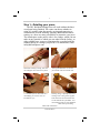
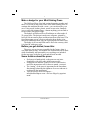
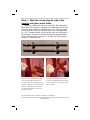
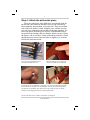
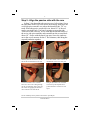
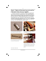
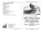
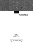
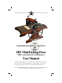
Sustainable printmaking experiences
DIY Mini Etching Press
Make a personal-size etching press
User Manual
Above: The Mini Etching Press is shown is shown after assembly, with the quarter-inch
chase on the press bed. The photographs inside—and videos online—appear varied
because they show models in different woods and are finished in different ways.
Originated by Bill Ritchie, Co-designer of the Mini Etching Press
2
Step 1—Detailing your press
The DIY Kit Mini Etching Press will work without the three
wood parts being finished. The owner can choose whether to
stain, oil, varnish, paint, decorate by carving and engraving or
combinations of wood finishing. Sanding, additional decorative
routing, etc., there are many possibilities to customize your press
The round space on the passive side is for a badge, which you can
make in any material or which you can order from the factory, as
either a blank brass, copper or aluminum disc or etched with the
standard design or a design you provide. For information, email
[email protected]
Sand before staining or oiling, start with
120 sandpaper, then steel wool to polish.
Among embellishments are the laser
print transfer with a hot transfer tool.
A 1 3/4-inch space has been made for a
round badge you create or have custom-made for you.
Staining, oiling, or painting comes after
sanding. Teak or Tung oils are popular.
Some stains have the oil included. Follow the instructions by the maker. Test
the finishing product on your embellishments before proceeding.
Video under construction
© 2013 Bill Ritchie
3
Make a badge for your Mini Etching Press
The Halfwood Press Line had various decorative touches and
there is a cut-out on the passive side of the Mini Etching Press to
continue this tradition but with a twist—you can also make your
own. Using wood, leather, plastic, metal or cast resin, found objects or recycled printing plates—almost anything you can find or
create will be your press’ badge.
The badges at Halfwood Press Workshops are often made of
22-gauge brass. The design is made on a computer, printed by
laser on silicon transfer paper and then ironed on to the brass. The
fused laser toner acts as a resist so when the brass badge is immersed in Edinburgh Etch, only the exposed parts are eaten away.
The badge is cut out and filed until it fits in the cutaway, then
it is glued in with epoxy glue.
Before you get started, know this:
The press you receive was assembled at the factory, then it
was taken apart to ship. This manual was written and videos made
while disassembly and reassembly so everything was included.
On the next page is the list of parts and the tools needed.
Some features about the press
•
•
•
•
Each press is hand-tooled, so the parts are not interchangeable with ALL other of the same model.
Some parts are marked A and P for Active and Passive,
and if the instructions call for these to match, you must.
The “tuning” of the press is important for the smoothest
functioning; balancing the tightness of screws and nuts is
explained in the instructions.
You can always email for support—
[email protected]—and use Skype by appointment.
© 2013 Bill Ritchie
4
Tools included
Allen wrench, size 5/64” (2 each)
Allen wrench size 1/8” (1 each)
Philips screw bit for barrel nuts, in-handle combo
Open, box-end combination 5/16” wrench
Materials, supplies you need
Printmaking paper (for testing the finished press)
Light machine oil (3-in-1)
Test plate
1 3/4” diameter badge blank
Parts and accessories in the kit
1. Hood piece, drilled and tapped
2. Open-end wrench, 5/16 open, box end combination
3. Hood hex socket screws, 5/32” (4) require the 5/64” Allen wrench
4. Mini Press core, pre-assembled, 1 1/2” solid rollers with precision bearings, pressure
screws and synchronizing chain, drive shaft fitted with spur gear for driving the bed
rack and four cross-ties, two with 4 bearings
5. Customized Philips screw driver bit, 1/4”
6. Hood barrel nuts, 5/32” (4 each)
7. Allen wrenches, (1) 1/8” and (2) 5/64”
8. Custom 3/16” barrel nuts for core and cross-ties (12 each)
9. Cross ties (2) 3/16 threaded rod fitted with bearings and jamb nuts
10. Two hardwood side pieces, (1 active, 1 passive)
11. Mini Press bed, fitted with steel rack, 1/4” polycarbonate, 6” X 14 1/2”
12. Wheel with 1/4” set screw (accepts the 1/8” Allen wrench)
13. PVC Chase, cut for 5" X 7" format for 1/4" thick printing block
14. New sizing catcher and roller felt blankets, 6” X 12”
15. Manual (this manual, not shown in the photos)
The 5/16 open-end, box end combination wrench is provided, as is the driver kit, which
has five parts fitted inside the hollow handle. The driver shaft inserts into the handle,
and it is magnetic so that the driver tips do not fall out. Note that only the blunt-end
Philips driver is to be used on the barrel cap nuts.
© 2013 Bill Ritchie
5
1
4
2
5
6
3
7
8
9
10
1
12
1
1
© 2013 Bill Ritchie
6
Step 2—Attach the hood to the press core
The hood is custom fit to each core. The active and passive
sides are indicated by the letter A and P on each end, assuring the
best alignment of the holes and the barrel cap nuts. The active end
matches the side where the driving shaft extends. With the hood
in place, the threaded, black 1” hex socket screws are inserted.
Using the 5/64” Allen wrench, turn the black screws in until
about 1/8” inch remains visible in the recessed holes, allowing for
the barrel cap nuts to be fitted on and turned in.
The core of the press needs a hood, and
the hood is custom fitted to the core.
The length of the core is precisely correct for proper tension of the chain.
Hood has “Active” (A) and
“Passive” (P) ends, made of hardwood
and milled to fit the core. It attaches
with four threaded screws and cap nuts.
Threaded screws are turned into the
threaded holes of the hood, leaving
about 1/8” for cap nuts.
Barrel cap nuts fit the threaded screws
and are tightened with the customized
Philips hex screw bit. Do not use great
force on cap nuts as they are aluminum
and therefore liable to strip.
See the video input https://www.youtube.com/watch?v=i6xLKvyLEqI
© 2013 Bill Ritchie
7
Step 3 – Start two connecting tie rods in the
passive side piece ends’ holes
The passive hardwood side piece, marked P, has unthreaded
holes drilled in the ends to accept the two connecting tie rods, and
four holes in the middle to attach the press core. The connecting
tie rods also have an active end and a passive end, distinguished
by a 5/16” jamb nut which will secure the rod in the final steps of
the assembly. The passive end slips through the unthreaded hole
at the end of the passive side piece. Cap nuts will fit the end protruding 1/8”inside the hole.
Two threaded steel cross-tie rods have a passive end, with jamb nuts and an active end
On the passive, side, which is marked
with a P, insert the end of the threaded
cross tie rod through each hole in the
end. These holes are not threaded, so the
rod slips in. Be sure it is the end with the
jamb nut- - small net on this end of the
rod; run the nut all the way to the bearing for best results.
With both threaded rod cross tie rods in,
set the passive side piece aside for now
as it will be attached after the active side
piece is secured to the core with its four
barrel cap nuts.
See the video https://www.youtube.com/watch?v=ptv1Odipolc
© 2013 Bill Ritchie
8
Step 4 - Attach the active side piece
The active side piece of the Mini Press core has the shaft for
the driving wheel and four threaded cross tie rods (which may
have temporary nuts on them, to be removed). They extend from
side of the core about 1/4-inch. Align the core with the wood active side piece with the five holes and slip the parts together. Use
barrel cap nuts to hold the piece in place. Grip threaded rods to
keep them from turning while you turn the barrel nut caps. Check
the passive side to see that 1/4-inch of threaded rod shows. Check
that the distance between the steel sides is slightly over 6 inches,
held by the jamb nuts inside.
The core has four threaded cross-tie
rods ends extending about 1/4”.
When the side piece is on, about 1/8”
can be seen inside the recessed holes.
The barrel cap nuts are aluminum, a soft metal, so do not use too much force because
the threads may be stripped or the slots damaged. Use only the custom Philips driver
bit; other drivers do damage. Start the barrel cap nuts, being sure they are started
straight to avoid stripping the threads, and then tighten them.
See the video https://www.youtube.com/watch?v=ptv1Odipolc
© 2013 Bill Ritchie
9
Step 5 - Align the passive side with the core
In Step 3, the threaded rod cross ties were left waiting. Screw
the jamb nuts all the way back next to the bearings, then press the
wood side piece onto the core where the threaded rods’ 1/4” extends. When the passive wood side is on, about 1/8” of the rod
can be seen in the hole. Use barrel cap nuts to secure the side.
Turn each of the cross ties’ active ends into the threaded holes of
the active side piece until the ends extend from the recessed hole
about 1/8”. Secure with the barrel cap nuts. Screw the jamb nut
out to the wood, measure for the 6” bed clearance, then bring the
cap and jamb nuts together.
With the jamb nuts moved back, fit the
side on the four threaded cross tie rods.
Turn the threaded cross tie rod into the
threaded hole in the active side piece.
Turn the threaded cross tie rod until
about 1/8” can be seen coming through,
out the recessed holes. Start a barrel cap
nut on this end, gripping the threaded
rod so it doesn’t turn with the nut.
Bring the jamb nuts to the wood and
secure the cap nut and jamb nut together. Measure to check for 6” bed
space.
See the videohttps://www.youtube.com/watch?v=ptv1Odipolc
© 2013 Bill Ritchie
10
Step 6 - Tighten all the barrel cap nuts and the
jamb nuts in the steel core together
The barrel cap nuts are aluminum, which is a comparatively
soft metal, so do not use excessive force when tightening them
and use only the blunt-ended Philips hex driver bit for the barrel
cap nuts. They need only be snug. The jamb nuts on the ends of
the wood side pieces, located inside the passive side, should be
snug against the wood. The purpose of the jamb nuts is to keep
the outer cap nut tight against the wood. Use a 5/16” combination
wrench for tightening jamb nuts. There are jamb nuts inside the
steel core, too, which should be checked again.
Use only the blunt-ended Philips driver
bit provided for the barrel cap nuts.
The jamb nuts in the passive side are to
be snug against the wood.
Use a 5/16 open-end / box end combination wrench on the jamb nuts.
Jamb nuts inside the steel core are important to determine the 6” space where
the bed travels, and so, too, the cap nut
and jamb nuts on the ends of the side
pieces.
Video under construction
© 2013 Bill Ritchie
11
Step 7—Check the three driving shaft set
screws on the spur gear, collar, and hub
There are two set screws on the spur gear and one on the retainer collar, a total of three set screws on the drive shaft tightened at the manufacturer’s. Be familiar with these to ensure that
they are always tight in keeping your Mini Press in good working
order. If the spur gear set screws loosen, it will slip on the shaft.
Use the 5/64” Allen wrench to tighten these, remembering never
to use worn Allen wrenches. The wheel hub set screw, likewise,
must be tightened with the 1/8” Allen wrench.
The spur gear has two set screws.
The collar has one set screw.
There is a fourth set screw on the
wheel hub which takes the larger Allen
wrench to tighten.
Two or three drops of light oil on the
threaded pressure screws will make
them turn more smoothly.
Video unders construction
© 2013 Bill Ritchie
12
Step 8 — Attach the wheel
The wheel is hand-crafted steel with a 1/4” set screw in the
hub. The 1/8” Allen wrench provided is for tightening the set
screw. When attaching the wheel, note that there is a flat spot on
the shaft for the set screw is to be seated. The flat spot ensures
that the hub will not turn on the shaft when you turn the wheel.
When tightening the set screw, never use an Allen wrench that
shows wear. If it slips, then the edges inside the set screw wear
and the set screw cannot be loosened to remove it, nor can it be
tightened to prevent the wheel from slipping. The wheel is handcrafted so, if it wobbles when spun, do not worry because does
not affect the press’ performance.
Use the 1/8” Allen wrench for the driving wheel hub set screw.
Loosen set screw to clear the shaft in
order to slip it on the shaft to the flat
spot where it is to be set.
Align the set screw with the flat spot on the
shaft and slip the hub on to the shaft.
When you are certain the screw is on the
flat spot, tighten the set screw all the
way down and then tighten it hard so the
set screw “bites” into the steel of the flat
spot on the shaft.
See the video https://www.youtube.com/watch?v=RziRWZh1zk0
© 2013 Bill Ritchie
13
Step 9 - Finishing the press bed
The bed is 1/4” thick polycarbonate, sometimes called Lexan
after its original industry name. This sheet cut to size, milled and
drilled for fitting with a steel rack. As it comes from the supplier,
it is covered with protective paper or plastic, and the corners are
sharp. For appearance you may want to round the corners and soften the edges and then remove the protective coverings. Recovering with clear, smooth adhesive Contact paper is recommended. Tools for this step are files, knife, squeegee, ruler, cutting surface and a bench stop.
Filing corners and edges
Measure, cut new covering.
Attach covering by one end to the tabletop, with the other end of the bed
stopped. Put the Contact paper readingside down. Turn it over and start to peel
the backing away about two inches, then
drag the squeegee and peel at the same
time all the way to the end.
A window-washer-style squeegee is
ideal to helping avoid bubbles. If bubbles form, make a tiny hole and press
out the trapped air. Trim the excess.
See the video https://www.youtube.com/watch?v=N_NSOdXRfwM
© 2013 Bill Ritchie
14
Step 10—Tuning and adjusting a Mini Press
Thinking of a press as being an “instrument” is like thinking
of a musical instrument—to the visual artist who makes prints,
the printing press is what a guitar is to a musician. Fine tuning
factors include the feel of the pressure screws and the movement
of the bed. Again, using the wrenches are essential to this and if
anything has changed while you put your press together, now is
the time to go over the assembled press to see that it works as
well as it was designed to work.
The space between the bed and the side
piece needs to be only enough to allow
free movement.
The chain should not be taught, but
slightly loose or else the pressure screws
will be hard to turn or jerky feeling.
Barrel cap nuts fit the threaded screws
and are tightened with the customized
Philips hex screw bit. Do not use great
force on cap nuts. They are aluminum
and the threads will be damaged if you
use to much force..
Jamb nuts secure the position of the
parts and a 5/16” open-end wrench fits
these.
Video under construction
© 2013 Bill Ritchie
15
Step 11 -Testing your press: Printing intaglio
The Mini Etching Press is capable of printing all four printing
processes, alone or in combination, plus monoprints and monotypes, too. These presses were designed to serve mainly as an
etching press for intaglio printmaking, and the designer made
many YouTube videos to demonstrate intaglio printing online.
The pictures give a brief overview of the steps for printing intaglio. The space in this manual does not allow for other printing
methods—stencil, relief, planographic, monotypes and mono
prints— referred to in the comments on uses of the chase.
Ink and wipe a plate intaglio.
Adjust pressure, using both hands.
Place damp paper on the plate, settle
felt blankets and turn the bed through.
A slow motion turning is recommended, without stopping until you
feel the roller pass of the end of the
plate.
Assign moment number and pull the
proof
Video under construction
© 2013 Bill Ritchie
16
Step 12—Uses of a chase
With the chase on the bed, you can print a relief block up to 5
X 7 inches for plates 1/4” thick or under. Plate glass or Mylar are
used in waterless lithography—vitreography—printing as well as
polymer “lithograph” plates. Pochoir (stencil) methods plus
monotypes and monoprints work on this rack-driven bed press.
Thicker blocks up to .918-inch (type-high) require a thicker chase
or type-high rails place alongside; a type-high block the same size
as the bed is shown below.
Relief blocks can be printed face up or
face-down. Thick blocks need spacers.
Vitreography uses either quarter-inch
ground plate glass or frosted Mylar.
For a type-high block, such as mounted
linoleum, use a long block or place typehigh runners on each side of small
blocks. For other sizes, build up your
chase with strips or use the chase as a
template to cut new ones of your choice
of thickness. The block above is simulated, the art is Mary Czerniski.
Pochoir, or stencil, methods work well
alone or with intaglio, monoprint and
monotype. The image above is a simulation.
Video to come under construction
© 2013 Bill Ritchie
17
A Note about maintenance
Check the set screws on the driving shaft and the driving
wheel hub, but not so often as to wear down the corners on your
Allen wrenches. Don’t overdo it.
The felt blankets need little care unless they get stiff from too
much sizing in the sizing catcher, in which case wash in cold water. Do not to leave the blankets under the roller. Damp blankets
will rust the steel.
The polycarbonate press bed is tough and strong, but not
scratch-resistant. Long use will dull the polish. An adhesive plastic coating is recommended if you want to save the original finish.
Print with thin, damp newsprint under your printing plate when
printing to help prevent plates thicker than 22 gauge from skidding ahead of the top roller.
18
Disassembly of the Mini Etching Press
1. Remove the bed
2. Remove the wheel. Loosen the ¼” Allen set screw with the
1/8” Allen hex wrench, bringing it out far enough so that the
wheel slips off the shaft. It is not necessary to remove the set
screw all the way.
3. With the blunt-end Phillips screw driver tip, remove the
two barrel cap nuts on the ends of the passive side which hold the
threaded rods. The passive side is opposite the side where the
wheel and shaft are, and the holes for the threaded rod are
smooth, not threaded, so they will slip out later on.
4. From the active side, remove the two barrel cap nuts off the
ends of the threaded steel rods. The holes in the wood active side
piece are threaded, so the rod is firmly attached and will be turned
out later on.
5. On the passive side, where the threaded rod enters the
wood, draw (screw) the jamb nut until it is all the way to the bearing retainer nut. Do this ONLY on the passive side, not on the
active side.
6. With a gripper or wearing rubber (Nitrile, latex, etc.) gloves
to assist your work, use your fingers to turn the threaded rod so it
unscrews from the threaded hole in the wood active side. You
must turn it counter-clockwise to unscrew it.
7. Turn the press upside down and balance it either on its Tshaped pressure screw handles or, for a more stable balance, a
thick book or a block of wood. Stand it with the passive side facing you and remove the four barrel cap nuts holding the passive
wood side piece to the steel core.
8. With the barrel cap nuts removed, the wood side piece will
come off although you may find the threaded rods will hang by a
thread and if so, turn them out gently and then remove the rods
from the wood side piece.
9. Turn the steel core around and remove the four remaining
barrel cap nuts in the active wood side piece. This frees the side
piece and it can be lifted off and the steel core set upright for stability.
10. To remove the wood hood piece, first take off the four
barrel cap nuts. Note that these are smaller than the other twelve
barrel cap nuts used on the side pieces and threaded rods.
11. Exposed are the four, one-inch long hex socket screws
which must be taken out if the wood hood piece is to be removed.
© 2013 Bill Ritchie
19
The 5/64 Allen wrench is for this purpose (as well as other setscrews on the press). The wood piece can now be lifted out. Note
that the wood hood piece is marked with a P and A for passive
and active as these pieces are machined to fit and may not fit if
they are switched end for end.
Background of the Mini Etching Press
Congratulations in beginning your experience in printmaking
from the press up. Few people have had the opportunity to take
up or continue printmaking from this point and build up their personal etching press from its parts. Some of the parts included in
the collection are already assembled because they require specialized tools and know-how, but most if the assembly is provided for
you.
Background of the DIY Kit
The DIY Mini Etching press kit was designed in 2013 in response to several requests for plans or kits to make a Mini Halfwood Press. This is a cost-effective alternative to other hand
printmaking presses. The Mini Etching press is small, affordable
and esthetically appealing. Bill Ritchie has been designing and
making Halfwood Presses since 2004, and the experiences he
gained made it possible to direct his co-worker, Tom, to an ideal
size and design for delivery as a kit.
More learning resources
Bill’s personal website is www.ritchie-art.com, and on the
homepage, trace around the frame to find TEACHING, for YouTube offerings. On YouTube, search terms OMEMERALDA,
HALFWOODPRESS, AND PRINTMAKINGVIDEOS. For
books by Bill Ritchie, including Kindle eBooks, go to amazon.com and use the author’s name to search. Titles include:
Halfwood Press: The Story (Memoir); The Art of Selling Art;
Swipe: A screen play; Travel Tapes: A professor’s Big Gamble
(Non-fiction); Rembrandt’s Ghost in the New Machine (Novel);
Cascades: Ten years of Great Notions (Non-fiction); and others.
See the video: https://www.youtube.com/watch?v=ulZNPqKfJsE
© 2013 Bill Ritchie
20
The Ritchie Family Art Gallery in Seattle, USA
The illustrations and videos were made in the Ritchie Family Mini Art Gallery in the
Residence on 5th Avenue, 812 5th Avenue North, C-2, Seattle, WA 98109, open by
appointment. The gallery is also where Bill does most of his computer graphics work
and Skype voice-and-video sessions. The QR code will link your device to the Website,
or enter www.ritchie-art.com in your browser.
Concept by Bill Ritchie
Bill Ritchie, 2004
Bill Ritchie’s goal is an online teaching company
for 21st Century printmakers, blending printmaking and digital arts that combine smart minietching presses with stories, games and movies.
He Co-designed the Mini Etching Press. He
started Emeralda Works in 1992 for teaching,
research, production and services in fine arts.
Mailing address: 500 Aloha #105
Seattle WA 98109
www.printmakingworld.com
Email: [email protected]
Skype: bill.h.ritchie
© 2013 Bill Ritchie