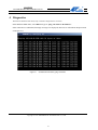
1
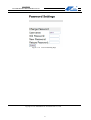
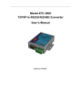
Model ATC-3000
TCP/IP to RS232/422/485 Converter
User’s Manual
Updated on 2015/01/15
Tel: +86 755‐8345‐3318
Fax:+86 755‐8355‐5891
http://www.szatc.com
Important Announcement
The information contained in this document is the property of SHENZHEN ATC TECHNOLOGY CO.,LTD. and is
supplied for the sole purpose of the operation and maintenance of products of SHENZHEN ATC TECHNOLOGY
CO.,LTD. No part of this publication is to be used for any other purposes, and it is not to be reproduced, copied,
disclosed, transmitted, stored in a retrieval system, or translated into any human or computer language, in any form, by
any means, in whole or in part, without the prior express written consent of SHENZHEN ATC TECHNOLOGY
CO.,LTD.
Published by
SHENZHEN ATC TECHNOLOGY CO., LTD
Room 809, Taikang Building, Tairan Industrial & Trading Zone, Futian District, Shenzhen China
Latest product info: http://www.szatc.com
Phone: +86 755‐8345‐3318
Fax: +86 755‐8355‐5891
E-mail: [email protected]
[email protected]
Copyright © 2011 SHENZHEN ATC TECHNOLOGY CO., LTD. All rights reserved.
All other product names referenced herein are registered trademarks of their respective companies
Contents
Important Announcement............................................................................................................. 2
Published by .................................................................................................................................. 2
Contents..........................................................................................................................................I
1
Introduction............................................................................................................................. 1
2
Hardware Setup ...................................................................................................................... 2
2.1 LED Indicators..............................................................................................................................................2
2.1.1 LINK LED .........................................................................................................................................2
2.1.2 ACT LED...........................................................................................................................................2
2.1.3 SPEED LED ......................................................................................................................................3
2.1.4 PWR LED..........................................................................................................................................3
2.2 Installation Procedures..................................................................................................................................3
3
Software Setup......................................................................................................................... 4
3.1 Configuration by Telnet ................................................................................................................................4
3.1.1 Login to the System ...........................................................................................................................4
3.1.2 Connection 0 setting ..........................................................................................................................5
3.1.3 Network Settings................................................................................................................................7
3.2 Configuration Using Web Browser...............................................................................................................9
3.2.1 Log in to the System ........................................................................................................................10
3.2.2 Network setting................................................................................................................................10
3.2.3 Hostlist setting .................................................................................................................................12
3.2.4 Hostlist setting .................................................................................................................................12
3.2.5 Change Password.............................................................................................................................14
4
Diagnostics............................................................................................................................. 16
Appendix A: How to make a virtual serial port ......................................................................... 17
I
User Manual
ATC-3000 TCP/IP to RS232/422/485 Converter
1
Introduction
Many industrial and Commercial devices equipped with slow serial communication ports RS-232, RS-485,
and RS-422 are limited in their transmission distance of 15 m. Examples of these devices are PLC controllers,
card readers, display signs, security controls, CNC controller, etc. The ATC-3000 is designed to transmit data
between serial device and TCP/IP device through Ethernet, and hence enhance the accessibility of the serial
device through the ubiquitous TCP/IP based Ethernet.
ATC-3000 offers full-duplex, bi-directional data transmission transparent between serial port and Ethernet
network. Flexible configuration options enable this unit to be setup over Web browser, or other Windows
utilities. Packed in a rugged metal housing for wall or DIN-Rail mount with 9~24VDC wide power input range,
ATC-3000 is ideal for almost any industrial and manufacturing automation.
Packaging
Please check ones package contains the following items:
§
ATC-3000 x 1
§
Power Adapter 9~24VDC x 1
§
Product CD containing configuration utility x 1
§
ATC-3000 TCP/IP to RS-232/422/485 converter quick start guide x 1
1
User Manual
ATC-3000 TCP/IP to RS232/422/485 Converter
2
2.1
Hardware Setup
LED Indicators
2.1.1 LINK LED
Message
Description
Off
Ethernet Disconnected
On
Ethernet Connected
Table 1. LINK LED Message
2.1.2
ACT LED
Message
Off
Blinking
Description
No data is transmitting between Ethernet and serial port
Data is transmitting between Ethernet and serial port
Table 2. ACT LED Message
Copyright © 2014 SHENZHEN ATC TECHNOLOGY CO., LTD.
2
User Manual
ATC-3000 TCP/IP to RS232/422/485 Converter
2.1.3 SPEED LED
Message
Description
On
Ethernet is working in 100Mbps
Off
Ethernet is working in 10Mbps
Table 3. SPEED LED Message
2.1.4
PWR LED
Message
Description
On
Power on
Off
Power off
Table4. PWR LED Message
2.2
Installation Procedures
Step 1: Connect ATC-3000 to power source using 9~24V DC Jack.
Step 2: Connect ATC-3000 to you PC or other device by Ethernet cable.You can use a standard straight-through
Ethernet cable connect it to a hub/switch, or connect it to PC‘s Ethernet port via a cross-over Ethernet cable.
However, in this case one need to make sure the PC is in the same sub-net as ATC-3000.
Step 3: Connect ATC-3000’s serial port to a serial device.
Step 4: Placement options. One can mount ATC-3000 to a wall/panel (Mounting screws included) or Din-Rail
rack.
Copyright © 2014 SHENZHEN ATC TECHNOLOGY CO., LTD.
3
User Manual
ATC-3000 TCP/IP to RS232/422/485 Converter
3
Software Setup
ATC-3000 is shipped with default settings shown in the following table:
Property
Default Value
IP Address
192.168.0.250
Gateway
192.168.0.1
Subnet Mask
255.255.255.0
User Name
admin
Password
admin
COM 1
9600,None, 8, 1, No flow control, Pack Control disabled, Buffer disabled
Link 1
Type: TCP Client, Listen port 27010, remote host=0.0.0.0
3.1
Configuration by Telnet
You can use Telnet utility to change configuration settings of ATC-3000 by following steps:
3.1.1
Login to the System
Open Ms-DOS command prompt window
Telnet to ATC-3000 using command “Telnet IP address”. ( For example:Input Telnet 192.168.0.250 in
Ms-DOS command prompt window).After telnet to ATC-3000, system prompts for a password, the default
password is left it blank. (Figure 3.1)
Figure3. 1 Login to the system
Note: One can press the default button of ATC-3000 to reset the password to the default value.
After verifying the password, the following terminal screen appears.( Figure 3.2)
Copyright © 2014 SHENZHEN ATC TECHNOLOGY CO., LTD.
4
User Manual
ATC-3000 TCP/IP to RS232/422/485 Converter
Figure3. 2 Main menu
Note: Changes to networking parameters will take effect only when one save and reboot ATC-3000.
Select “1” from “Input choice and enter (1~7 or v s q):” to enter show basic settings page as
following.( Figure 3.3)
Figure3. 3 Basic settings
This page gives you the general information of ATC-3000.
3.1.2
Connection 0 setting
Select “2” from “Input choice and enter (1~7 or v s q):” to enter show Connection 0 setting page as following.
Copyright © 2014 SHENZHEN ATC TECHNOLOGY CO., LTD.
5
User Manual
ATC-3000 TCP/IP to RS232/422/485 Converter
( Figure3.4)
Figure3. 4 Connection 0 setting
In this page you can change the network mode of ATC-3000.And then you can configuration the parameters of
the mode which you choice. Figure 3.5 and figure 3.6 show the configuration page.
Figure 3. 5 Tcp configuration page
Copyright © 2014 SHENZHEN ATC TECHNOLOGY CO., LTD.
6
User Manual
ATC-3000 TCP/IP to RS232/422/485 Converter
Figure3. 6 Udp configuration page
3.1.3
Network Settings
Select “3” from “Input choice and enter (1~7 or v s q):” to enter show Network setting page as following.
( Figure 3.7)
Figure3. 7
3.1.3.1
Network settings page
Static IP setting
Select “1” from “Input choice and enter (1~9 or m q):” to enter show Static IP setting page as following.
( Figure 3.8)
Copyright © 2014 SHENZHEN ATC TECHNOLOGY CO., LTD.
7
User Manual
ATC-3000 TCP/IP to RS232/422/485 Converter
Figure3. 8 Static IP setting page
In this page you can change the static IP address, subnet mask, default gateway and some other parameters.
3.1.3.2
Auto IP setting
Select “2” from “Input choice and enter (1~9 or m q):” to enter show Static IP setting page as following.
( Figure 3.9)
Figure3. 9
3.1.3.3
Auto IP setting page
Ethernet configuration
Select the No. between 3 and 8 from “Input choice and enter (1~9 or m q):” to enter show Ethernet
configuration page.
3.1.4 Hostlist 0 Settings
Select “4” from “Input choice and enter (1~7 or v s q):” to enter show Hostlist 0 setting page as following.
( Figure 3.10)
Copyright © 2014 SHENZHEN ATC TECHNOLOGY CO., LTD.
8
User Manual
ATC-3000 TCP/IP to RS232/422/485 Converter
3.1.5 Serial 0 Settings
Select “5” from “Input choice and enter (1~7 or v s q):” to enter show Serial 0 setting page as following.
( Figure 3.11)
Figure 3. 10
Hostlist 0 setting
Figure 3. 11 Serial 0 setting
In these pages you can configuration the parameters about the serial port and hostlist.
3.2 Configuration Using Web Browser
1. Make sure one PC is located on the same network sub-net as ATC-3000
Open a web browser, then type in the IP address of ATC-3000 to be configured. Default user name is admin and
default password is admin.
2. ATC-3000’s network, link mode and COM ports settings can be configured in different web pages.
Click to confirm the parameter which you have changed.
3.
Click “Apply/Restart” to save settings and reboot ATC-3000.
To do so, please follow the steps below.
Copyright © 2014 SHENZHEN ATC TECHNOLOGY CO., LTD.
9
User Manual
ATC-3000 TCP/IP to RS232/422/485 Converter
3.2.1 Log in to the System
1. From web browser, type in the IP address of ATC-3000 in the URL. Example: http://192.168.0.250
The following authentication screen appears.(Figure 3.12) Please type in user name and password then click on
OK. The user name is admin and password is left it blank by default.
Figure 3. 12 login the system via Web
2.
The following home page appears.( Figure 3.13)
Figure3. 13 Home page
3.2.2 Network setting
Click on the “Network” link and the following screen appears. In this page you can configuration the IP
information. Figure3.14.
Copyright © 2014 SHENZHEN ATC TECHNOLOGY CO., LTD.
10
User Manual
ATC-3000 TCP/IP to RS232/422/485 Converter
Figure3. 14 Network setting page
Copyright © 2014 SHENZHEN ATC TECHNOLOGY CO., LTD.
11
User Manual
ATC-3000 TCP/IP to RS232/422/485 Converter
3.2.3 Hostlist setting
Click on the “serial tunnel 0” link and then click on the “hostlist” link you will see the figure 3.15 below.
Figure3. 15 Hostlist setting page
3.2.4 Hostlist setting
Click on the “Channel 0” link and then click on the “serial settings” link you will see the figure 3.16 below.
Copyright © 2014 SHENZHEN ATC TECHNOLOGY CO., LTD.
12
User Manual
ATC-3000 TCP/IP to RS232/422/485 Converter
Figure3. 16 Serial setting page
Click on the “Channel 0” link and then click on the “connection” link you will see the figure 3.17 below.
Copyright © 2014 SHENZHEN ATC TECHNOLOGY CO., LTD.
13
User Manual
ATC-3000 TCP/IP to RS232/422/485 Converter
Figure 3. 17 connection setting page
In these pages you can configuration some parameters about the serial port and network mode.
3.2.5 Change Password
If you want to change the login Password you should click on the “Password setting” link. And then the page
like Figure3.18 you will see.
Copyright © 2014 SHENZHEN ATC TECHNOLOGY CO., LTD.
14
User Manual
ATC-3000 TCP/IP to RS232/422/485 Converter
Figure 3. 18 Password Setting Page
Copyright © 2014 SHENZHEN ATC TECHNOLOGY CO., LTD.
15
User Manual
ATC-3000 TCP/IP to RS232/422/485 Converter
4
Diagnostics
You can use Standard TCP/IP Utility Ping Command to diagnostics the connection.
From Windows start menu, select Run and type in “ping <TCP Server IP address>”.
If the connection is established, the Reply messages are displayed, otherwise it will indicate Request timed
out (Figure 4.1).
Figure4. 1
Standard TCP/IP utility ping command
Copyright © 2014 SHENZHEN ATC TECHNOLOGY CO., LTD.
16
User Manual
ATC-3000 TCP/IP to RS232/422/485 Converter
Appendix A: How to make a virtual serial port
Insert the software CD and you will find a file named vcom.rar , then open this file to setup the vcom software.
If you install the software correctly ,and then double-click the shortcut of this software
.The main interface will
appear like Figure A.1.
Figure A. 1
Click on the Virtual COM tab and choose Add you will see the interface show in Figure A.2.
You can change some parameter in this interface to establish a virtual serial port.
Ø Work Mode: you can select TCP server, TCP client or UDP mode. But here we choose TCP client as a
example.
Ø COM Port: you can select a serial port number which you want to mapping. This port NUM. must not in
use. We select COM2 here.
Ø Local Host and Local Port: keep default set.
Ø Remote Host: input the IP address of the device which you want to mapping. The IP address of the device
we use in the test is 192.168.0.251.
Ø Remote Port: input the port number of the device which you want to mapping. The port number of the
device we use in the test is 27010.
Ø Other parameter: keep them in default set.
If the work above is finished, click on OK. Then the interface like Figure A.3 will appear in front of you.
Copyright © 2014 SHENZHEN ATC TECHNOLOGY CO., LTD.
17
User Manual
ATC-3000 TCP/IP to RS232/422/485 Converter
Figure A. 2
Copyright © 2014 SHENZHEN ATC TECHNOLOGY CO., LTD.
18
User Manual
ATC-3000 TCP/IP to RS232/422/485 Converter
Figure A. 3
Copyright © 2014 SHENZHEN ATC TECHNOLOGY CO., LTD.
19