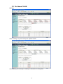
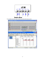
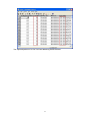
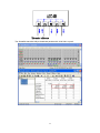
1
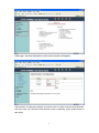
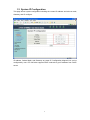
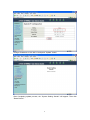
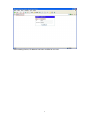
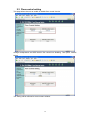
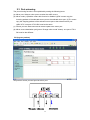
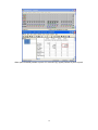
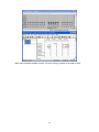
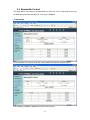
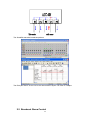
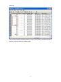
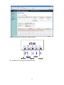
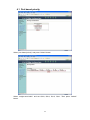
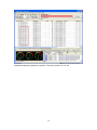
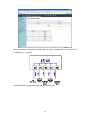
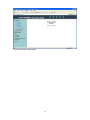
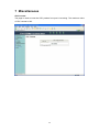
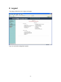
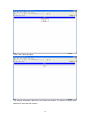
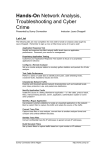
5-Port 10/100Mbps Fast Ethernet Switch ATC-405 Web management Software User Manuals 1 http://www.szatc.com Table of Contents 1 2 Administrator........................................................................................................ 1 1.1 Authentication configuration...............................................................1 1.2 System IP Configuration.....................................................................3 1.3 System status.......................................................................................6 1.4 Load default setting............................................................................. 7 1.5 Firmware update..................................................................................8 1.6 Reset device.......................................................................................10 Port Management.............................................................................................. 11 2.1 Port configuration...............................................................................11 2.2 2.3 2.4 2.5 3 4 5 6 7 8 Flow control setting........................................................................... 12 Port mirroring......................................................................................13 Bandwidth Control............................................................................. 21 Broadcast Storm Control.................................................................. 25 VLAN Setting......................................................................................................28 3.1 VLAN mode........................................................................................ 28 3.2 Port based VLAN............................................................................... 29 3.3 Tag based VLAN................................................................................37 QoS Setting........................................................................................................ 40 4.1 Port based priority............................................................................. 42 4.2 VLAN tag priority................................................................................45 4.3 TOS/DSCP priority............................................................................ 48 4.4 TCP/UDP priority............................................................................... 51 Security Filter..................................................................................................... 54 5.1 MAC ID filter....................................................................................... 54 5.2 Firewall................................................................................................ 57 Configuration Backup/Recovery......................................................................65 Miscellaneous.....................................................................................................68 Logout..................................................................................................................69 2 1 Administrator 1.1 Authentication configuration This page is used to change the user name and the password. Enter IP=192.168.2.1 at web site field. USER LOG IN diagram box will appear, and then enter correct ID and Password(the default is admin and system). The warning message will appear if enter incorrect username and password. 1 After login, the brief description of the main function will appear. Authentication Configuration diagram box allows user to modify username and password, and then enter new username and password. After completing, press update button to take effect. 2 1.2 System IP Configuration This page shows system configuration including the current IP address and sub-net mask, Gateway, and IP configure. IP address, Subnet Mask, and Gateway at system IP Configuration diagram box can be configured by user. ATC-405 also supports DHCP methods to get IP address from DHCP server. 3 Change IP Address to 192.168.2.5 and press “Update” button. After Completing update process, the “System Setting Saved!!” will appear. Then click “Reset Device”. 4 After resetting Device, IP address has been modified to new one. 5 1.3 System status This page is used to check the status of switch, including Switch MAC address and software version. The MAC address and version of .ATC-405 will be shown at system status diagram box. Comment field can accept Aa~Zz, excluding special character. 6 1.4 Load default setting Clicking the “Load default setting” button will make the switch being set to the original configuration. Note: this change only concerns the switch behavior, excluding the change for user name, password and IP configuration. After Completing load process, the “System Setting Saved!!” will appear. Then press “Reset Device” to take effect. 7 1.5 Firmware update After pressing firmware update button, the switch will erase the older version flash code first. Then enter file name at specific path, and the update will be completed. Enter password to execute firmware update process. After pressing “Update” button, the old web code will be erased. 8 Enter correct path and press “UPDATE” button to complete firmware update process. Firmware update is finished. 9 1.6 Reset device This page is used to reset device. Press “Confirm” button to take effect for rebooting device. 10 2 Port Management 2.1 Port configuration This page allows the user to configure operating mode of the physical port. After completing the settings, press “Submit” button to take effect. The setting will be reflected at current status window. 11 2.2 Flow control setting This page allows the user to enable or disable flow control function. Change backpressure and IEEE 802.3x flow control into disabling. Then press “Submit” button. The setting will be reflected at current status window. 12 2.3 Port mirroring The port mirroring function is accomplished by setting the following items. (a) Mirror port: Select a mirror port to monitor the traffic source. (b) Mirror mode: (1)Disable: means this function is disabled. (2)RX: means copy the incoming packets of the selected source port to the selected mirror port. (3)TX: means copy the outgoing packets of the selected source port to the selected mirror port. (4)RX & TX: one port of TX & RX must be the same. (c) Source port: the traffic source that will be copied to the mirror port. (d) Mirror source-destination pair (press “Change mirror mode” button): one port of TX & RX must be the different. RX (ingress packets) Set port2 as source port and port4 as mirror port. 13 The SmartBits transmits packets to port 2. When port2 forwards unicast packets to port3, ATC-405 will copy ingress packets of port2 to port4. TX (egress packet) 14 Set port3 as source port and port5 as mirror port. The SmartBits transmits packets to port2. 15 When port2 forwards packets to port3, ATC-405 will copy egress packets of port3 to port5. 16 TX and RX (one port of TX & RX must be the same) Set port3 as source port and port5 as mirror port. Traffic 1 and traffic 2 separately transmit packets to port2 and port3 at the same time. 17 ATC-405 copies egress and ingress packets of port3 to port5. 18 TX and RX (one port of TX & RX must be the different) After changing mirror mode, set port3 as source port, port2 as destination port and port5 as mirror port. The SmartBits transmits packets to port3. 19 When port3 forwards packets to port2, ATC-405 will copy packets of the path to port5. 20 2.4 Bandwidth Control This page allows the setting of the bandwidth for each port. The TX rate and Rx rate can be filled with the number ranging 0 to 3124 (0 for 100Mbps). TX bandwidth Fill in the blank of TX rate of port5 with 1000(x32Kbps) and press “Update” button. After updating, 32Mbps is displayed in the TX rate of port5. 21 The SmartBits transmits broadcast packets to port4. The RX bytes filed of 33-SX-7410 for port5 is 3907243 bytes. It is close to 32Mbps. 22 RX bandwidth Fill in the blank of RX rate of port4 with 100(x32Kbps) and press “Update” button. After updating, 3.2Mbps is displayed in the RX rate of port4. 23 The SmartBits transmits broadcast packets. The RX bytes filed of 30~33-SX-7410 is about 402321 bytes. It is close to 3.2Mbps. 2.5 Broadcast Storm Control 24 The broadcast storm control is used to block the excessive broadcast packets, the threshold ranging from 1 to 255. The broadcast storm of the port2 is enabled and threshold is set to 8. The broadcast packets will be dropped when broadcast packets are more than threshold setting (packet length is 64 bytes). 25 100M mode The smart bit transmits broadcast packets to port2. Port2 of ATC-405 will drop excessive packets if the broadcast packets get up to threshold value in unit time. Unit time: 10ms for 100Mbps mode. 26 10M mode The smart bit transmits broadcast packets to port2. Port2 will drop excessive packets in unit time. Unit time: 100ms for 10Mbps mode. 27 3 VLAN Setting 3.1 VLAN mode ATC-405 supports two VLAN modes, tag based and port based. When the port based VLAN is selected, the tag setting will be useless. When the tag based or port based VLAN is selected, the user can define the handling method of a VLAN tag to the specified port, including “add a VLAN tag”, “ remove a VLAN tag” or “don’t care” about VLAN tag. VLAN mode supports port based and tag based mode. Press “Change Mode” button to change VLAN mode. The egress packets of the output port will be added tag if add tag option is selected. The egress packets of the output will be stripped tag if remove tag option is selected. Don’t care means the egress packets of the output port only forward to destination without adding or removing tag. 28 3.2 Port based VLAN Add tag Select “add tag” for port2~5 and press “Update” button. After updating, the message of “add tag” is showed in VLAN tag field. 29 The SmartBits transmits 64byte broadcast packets without tag to port2. 30 The captured packets of 31 SX-7410 are added tag with 8100 0001. 31 Remove tag Select “remove tag” for port2-5 and press “Update” button. After updating, the message of “remove tag” is showed in the VLAN tag field. 32 The SmartBits transmits 68byte broadcast packets with 8100 0001 to port2. 33 The captured packets of 31 SX-7410 are removed tag. 34 VLAN member setting Choose port1-3 as VLAN members of port2 and press “Update” button. After updating, VLAN member field appears that port1-3 are in the same VLAN group. 35 The SmartBits transmits 64byte broadcast packets. Port4 and port5 have not received any packets. 36 3.3 Tag based VLAN This page is used to set the VLAN ID. The VLAN ID is valid only when the tag based VLAN is enabled. In port based VLAN mode, the VLAN ID is useless. Press “Change Mode” button to use tag based VLAN. Enable VLAN 0, VID=175 and p5 is added tag. Then press “Submit” button. 37 Set PVID of p2 to be 175 and press “Submit” button. The SmartBits transmits 64byte broadcast packets. 38 The captured packets from port5 are added tag. 39 4 QoS Setting This page provides priority classification for QoS. Priority classification: - Disable - Port based priority - VLAN tag priority - TOS/DSCP priority - TCP/UDP priority 40 This page provides a option of queue scheduling including strictly priority and weight-round-robin . 41 4.1 Port based priority Select “port based priority” and press “Submit” button. Select “weight-round-robin” and set Q3=8, Q2=4, Q1=2, Q0=1. Then press “Submit” button. 42 Set port2 queue0, port3 queue1, port4 queue2, and port5 queue3. Port2-5 forward 64byte TCP packets to port1. 43 Etherpeek captures packets from port2-5. The ratio of port2~5 is 1:2:4:8. 44 4.2 VLAN tag priority Select “VLAN tag priority” and press “Submit” button. Select “weight-round-robin” and set Q3=8, Q2=4, Q1=2, Q0=1. Then press “Submit” button. 45 Set VLAN priority 4 queue0, VLAN priority 5 queue1, VLAN priority 6 queue2 and VLAN priority 7 queue3. Port2-5 forward unicast packets with 64byte length to port1. 46 Etherpeek captures packets from port2-5. The ratio of VLAN priority 4~7 is 1:2:4:8. 47 4.3 TOS/DSCP priority Select “TOS/DSCP priority” and press “Submit” button. Select “weight-round-robin” and set Q3=8, Q2=4, Q1=2, Q0=1. Then press “Submit” button. 48 Set DSCP 7 queue0, DSCP 6 queue1, DSCP 5 queue2 and DSCP 4 queue3. Port2-5 forward unicast packets with 64byte length to port1. 49 Etherpeek captures packets from port2-5. The ratio of DSCP 4~7 is 8:4:2:1. 50 4.4 TCP/UDP priority Select “TCP/UDP priority” and press “Submit” button. Select “weight-round-robin” and set Q3=8, Q2=4, Q1=2, Q0=1. Then press “Submit” button. 51 Set pre-defined logical port0 queue0, pre-defined logical port1 queue1, pre-defined logical port2 queue2 and pre-defined logical port3 queue3. Port2-5 forward unicast packets with 64bye length to port1. 52 Etherpeek captures packets of port2-5. The ratio of pre-defined logical port0-3 is 1:2:4:8. 53 5 Security Filter 5.1 MAC ID filter This page is used to drop packets with specific SMAC or DMAC address. The MAC ID filter is only for unicast MAC address. 54 Fill in the blanks with “00:00:00:00:00:01” and select “enable”. Press “Update” button to take effect. 55 The SmartBits transmits packets with SMAC=00:00:00:00:00:01 to port2. Port2 of ATC-405 drops these packets. 56 5.2 Firewall This page provides the user to filter specific traffic or forward packets by bandwidth control. If incoming packets match a predefined entry, the corresponding action is performed. It is possible to match multiple entries for an incoming packet and then the first matching entry is effective. 57 Filter Fill in the blank of source logical port number of entry1 with 10000 and filter UDP packets. Then press “Submit” button. 58 After updating, the status of entry1 is updated. The SmartBits transmits packets with source logical port number=10000 to port5. 59 Port5 of ATC-405 drops these packets. 60 Bandwidth Fill in the blank of destination IP of entry2 with 192.168.10.10 and bandwidth with 100. Then press “Submit” button. 61 After updating, the status of entry2 is updated. The SmartBits transmits broadcast packets with destination IP=192.168.10.10 to port4. 62 The RX bytes filed of 30~33-SX-7410 is about 424029 bytes. It is close to 3.2Mbps. 63 Clear Entry Select entry1 and click “Clear” button. The status of entry1 is cleared. 64 6 Configuration Backup/Recovery This function provides the user with a method to backup/recovery the switch configuration. The user can save configuration file to specified path. If the user wants to recover the original configuration, which is saved at the specified path, entering the password and then pressing the “upload” button could recover the original configuration. The contents of the EEPROM can be saved to specific path, and press “Download” button. The default name of download file is down.bin. 65 After entering down.bin, enter correct password and then press update button to upload. The warning message will appear if entering bank or incorrect file format. The warning message will appear if entering incorrect binary file. 66 Press reset device to take effect. 67 7 Miscellaneous CRC Counter The page is used to count the CRC packets from port1-5 receiving. The maximum value of CRC counter is 255. 68 8 Logout The page provides the user to logout web page. Log out to exit web management system. 69 Press “Yes” button to logout. The warning will appear if idle time is more than five minutes. The system will logout when idle time is more than ten minutes. 70