1
®
Accuriss™57 Series
Integrated Motor, Drive & Control System
USA57
USER’S MANUAL
USA57
Revision 1.2
©2010 USAutomation, Inc.
All rights reserved
USAutomation© AccurissTM Series User's Guide
This manual, as well as the software described in it, is furnished under license and may be used
or copied only in accordance with the terms of such license. The content of this manual is
furnished for informational use only, is subject to change without notice and should not be
construed as a commitment by USAutomation. USAutomation assumes no responsibility or
liability for any errors or inaccuracies that may appear herein.
Except as permitted by such license, no part of this publication may be reproduced, stored in a
retrieval system or transmitted, in any form or by any means, electronic, mechanical, recording,
or otherwise, without the prior written permission of USAutomation.
USAutomation, Inc.
23011 Moulton Parkway
Suite J2
Laguna Hills, CA 92653
(949) 588-0513
(949) 588-8761 fax
www.usautomation.com
USA57
Revision 1.2
2
Contents
Contents ....................................................................................................... 3 Revision Notes ............................................................................................... 5 Product Returns .............................................................................................. 6 Unpacking ..................................................................................................... 6 Part Number Configuration ................................................................................. 7 Dimensions and Connection Pin out ...................................................................... 8 Mounting the USA57 ........................................................................................ 9 Mounting a Load to the USA57 ............................................................................ 9 Speed Torque Curves ..................................................................................... 10 Accuriss Communications ................................................................................ 12 Starter Kit ................................................................................................... 12 Command Set Table ................................................................................. 14 Programming Examples .................................................................................. 75 Appendix A .................................................................................................. 80 Homing Algorithm in Detail .......................................................................... 80 Appendix B .................................................................................................. 83 Device Response Packet............................................................................ 83 Command Response Modification ................................................................. 86 Appendix C ................................................................................................. 87 Heat Dissipation ...................................................................................... 87 Appendix D ................................................................................................. 88 Step Loss Detection using an Opto-sensor ....................................................... 88 Appendix E .................................................................................................. 89 Position Correction Mode and Overload Report Mode .......................................... 89 Appendix F .................................................................................................. 95 Appendix G ................................................................................................. 99 Appendix H ............................................................................................... 100 USA57
Revision 1.2
3
Appendix I ................................................................................................. 101 Appendix J ................................................................................................ 103 USA57
Revision 1.2
4
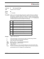
Revision Notes
Rev
Description
Date
1.0
1.1
1.2
Version 1 released
Changes to text to correct errors
Update part number, update error correction
6/14/10
6/18/10
7/26/10
USA57
Revision 1.2
5
Using This Manual
The Accuriss Series is a unique motor, drive and control all in one package. The USA57 is the
57mm version in this series and it is designed to be interactively controlled with a computer or
other industrial controller or may be preprogrammed to run complex subroutines from programs
stored in non-volatile RAM.
This manual provides the basic information necessary to unpack, set up, and configure the
USA57. If additional information is required beyond what is presented here, please refer to the
Support section of our website or contact USAutomation Applications Engineering.
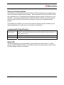
Product Returns
All returns for warranty or out-of-warranty repairs must first receive an RMA (Return Material
Authorization) number. Please contact USAutomation Customer Service Department with
information about the return and an RMA number will be issued if warranted.
Products returned to the factory will be examined and tested for failure mode and cause.
USAutomation Customer Service will contact the customer with the repair cost if the required
repair is out of warranty.
Unpacking
Carefully remove the USA57 from its shipping box and inspect the unit for any evidence of
shipping damage. Report any damage immediately to USAutomation. Please save the shipping
box for damage inspection or its use in returning product if necessary.
Please observe the following guidelines for handling and mounting of your USA57:
USA57
Do not drop the unit on any hard surface or subject it to any impact loads. Dropping the
unit or other impact loads may result in bearing damage or misalignment.
Do not drill holes into the motor. Drilling holes into the unit can generate particles and
machining forces that may affect the operation of the unit. USAutomation can supply the
USA57 with modifications to your drawing. Please contact the factory for a quote.
Do not expose the USA57 to mist, spray or submersion in liquids.
Do not disassemble the USA57. Unauthorized adjustments may alter the specifications
and void the product warranty.
Revision 1.2
6
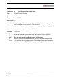
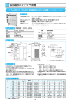
Part Number Configuration
The part number for the Microstage USA57 is determined as follows:
USA57
Revision 1.2
7
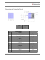
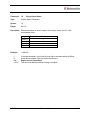
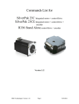
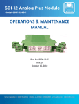
Dimensions and Connection Pin out
Part #
USA57-2106
USA57-2206
Pin #
1
2
3
4
5
6
7
8
9
10
11
12
13
14
15
16
USA57
“L” Dimension
2.96 in.
3.75 in.
Accuriss Pinout
Function
Power Ground (-V)
Output 1
Direction (DIR) Input
Opto isolated STEP & DIR +5VDC Power Input
Input 2
Internal Power for Opto-sensors
Input 3
RS485 A
+12 to +40 VDC (+V)
Output 2
STEP Input
Signal Ground
Input 1
Input 4
RS485 B
N/C
Revision 1.2
Color Code
Black
White/Brown
White/Yellow
White/Red
Violet
Orange
Gray
Yellow
Red
White/Black
White/Orange
Blue
Brown
Green
White
8
Mounting the USA57
Threaded mounting holes are located on the front of the Accuriss 57. There are four thru holes
with a 0.200 in. diameter. See Dimensions section for exact locations.
Mounting a Load to the USA57
The Accuriss 57 has 0.250 in. diameter shaft for mounting the load (see dimensions page).
Care should be used in isolating the motor bearing from thrust and axial loads. It is not
advisable to couple loads to the Accuriss shaft with a solid coupling as that may impose radial
loads on the motor bearings which will shorten the life of the motor. A flexible coupling, such as
those made by Helical (www.heli-cal.com), should be used.
USA57
Revision 1.2
9
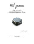
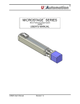
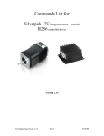
Speed Torque Curves
The base motor for the USA57 is a 1.8°/step 2-phase hybrid step motor. Full torque will be
available from the motor when used with a drive which has a rated output of at least 2.0 amps
per phase. Here are representative speed/torque curves for the two different lengths of motors
available. Individual applications may differ in motor performance:
USA57
Revision 1.2
10
USA57
Revision 1.2
11
Accuriss Communications
Communications to the Accuriss is possible with any RS485 compatible communication device
and any commonly available terminal program. Most computers have either an RS232 or USB
port (sometimes both). USAutomation offers software drivers for both on our web site or in our
Starter Kit. Commercially available USB to RS485 and RS232 to RS485 converters will allow
communications with the Accuriss from most computers using only a compatible terminal
program.
Also available as a software tool is the Accuriss Terminal software, which is available as a no
charge download from our web site, or it is included in our Starter Kit.
Communication Specifications
Electrical
Characteristics
In conformance with EIA-485 Use a twisted pair cable (TIA/EIA-568B CAT5e or
higher is recommended) and keep the total wiring distance including extension to
50 m (164 ft.) or less.
Baud rate
Selectable from 9570 bps, 19200 bps, 38400 bps (9570 is default)
Physical layer
Asynchronous mode (8 bits, 1 stop bit, no parity)
Starter Kit
The Accuriss Starter Kit is recommended for any first time user of the Accuriss 57. This kit
contains a USB to RS485 converter, an I/O break out board, two input switches, and a CD that
includes catalogs, manuals, and software.
USA57
Revision 1.2
12
Executing Commands
In order to execute a command or a series of commands, the following syntax should be used:
[/][Device Address][Command][Value]…{[Command]{[Value]}[R][<CR>]
Where,
/ = the start character. Data following the “/” character will be loaded into the communication
buffer.
Device Address = the device address. (Factory Preset)
Command = the command to be executed.
Value = a valid value for the command to be executed (position value, speed, etc).
Note: Up to fourteen (14) Commands and Values can be in a single command string.
R = Execute the command(s) in the communication buffer already received .
<CR> = Carriage Return+Line Feed (CR+LF) and indicates that the command string is
complete.
Example 1:
/1A1000R<CR>
“/” is the start of character. Lets Accuriss know that a command string is coming.
“1” is the device address. (This is preset at the factory)
“A” Instructs motor to move to an absolute position.
“1000” sets the absolute position to +1000 steps from the zero position.
“R” Instructs Accuriss to run the command(s) that are in the communication buffer.
“<CR>” tells Accuriss that the command string is complete and causes the command(s) to
be executed since the R was included in the command string.
Example 2:
Command string 1: /1A2000A0<CR>
Command string 2: /1R<CR>
For command string 1:
“/” is the start of character. Lets Accuriss know that a command string is coming.
“1” is the device address. (This is preset at the factory)
The first “A” instructs motor to move to an absolute position.
“2000” sets the absolute position to +2000 steps relative to the zero position.
The second “A” instructs motor to move to an absolute position.
“0” sets the absolute position to the zero position.
“<CR>” tells Accuriss that the command string is complete. Nothing is executed at this time
because the R command was not included in the command string.
For command string 2:
“/” is the start of character. Lets Accuriss know that a command string is coming.
“1” is the device address. (This is preset at the factory)
“R” Instructs Accuriss to run the command(s) that are in the communication buffer.
“<CR>” tells Accuriss that the command string is complete and causes both of absolute
position the commands to be executed since an R command is included in the command
string.
USA57
Revision 1.2
13
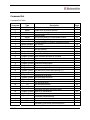
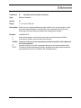
Command Set
Command Set Table
Command
A
P
D
Z
z
f
F
V
L
B
g
G
H
S
s
e
R
X
m
h
p
j
N
n
an
b
o
M
ar
aP
d
K
aA
USA57
Type
Motion
Motion
Motion
Motion
Motion
I/O
System Control
Motion Variable
Motion Variable
Motion Variable
Program Control
Program Control
Program Control
Program Control
Program Control
Program Control
Program Control
Program Control
System Control
System Control
Program Control
System Control
System Control
System Control
I/O
Communication
System Control
Program Control
System Control
System Control
I/O
Motion
Motion
Description
Absolute move in positive direction
Index move in positive direction
Index move in negative direction
Homes motor
Set current position to commanded number
Set home flag polarity
Change direction of rotation considered positive
Set velocity
Set acceleration rate
Set jog distance
Set beginning loop marker
Set number of loops
Halt command and wait for condition
Skip next command and branch on condition
Store program to address
Execute stored program
Run command string
Repeat running of command string
Set maximum current while moving (%)
Set maximum hold current (%)
Send string to terminal
Set microstep resolution
Set feedback mode
Set Accuriss mode
Set limit switch mode
Set baud rate
Microstep waveform correction factor
Wait for X milliseconds
Reset the Accuriss processor
Controller Response delay
Switch debounce delay
Backlash compensation factor
Oscillating (Sinusoidal) motion amplitude
Revision 1.2
Page
16
17
18
19
21
22
23
24
25
26
27
28
29
30
31
32
33
34
35
36
37
38
39
40
42
43
44
45
46
47
48
49
50
14
aW
J
?aa
at
?at
ao
am
ad
aC
aE
au
x
ac
u
T
?0
?2
?4
?6
?9
?10
&
Q
$
USA57
Motion
I/O
System Control
System Control
System Control
System Control
System Control
System Control
System Control
System Control
System Control
System Control
System Control
System Control
System Status
System Status
System Status
System Status
System Status
System Control
System Status
System Status
System Status
System Status
Oscillating (Sinusoidal) motion frequency
Turn Accuriss outputs on or off
Read back analog to digital converter values
Analog to digital converter threshold
Read back analog to digital threshold values
Position potentiometer offset value
Position potentiometer multiplier value
Position potentiometer deadband value
Position correction deadband range
Encoder to microstep resolution ratio
Overload detection retry limit
Fine position integration period
Fine position final error range
Recovery retries
Terminate current command
Return current position
Return current maximum speed
Return status of inputs
Return current microstep size
Erase all commands in EEPROM
Return 2nd encoder or step & direction input count
Return current firmware version
Return Accuriss current status
Return currently executing command
Revision 1.2
51
52
53
54
55
56
57
58
59
60
61
62
63
64
65
66
67
68
69
70
71
72
73
74
15
Command:
A
Absolute move in positive direction
Type:
Motion Command
Syntax:
An
Range:
n = 0 to 2,147,483,648
Description: Move motor to a positive absolute position relative to the 0 (zero) position. Once
at a given absolute position, executing the same command will not move the
motor again since the absolute position has already been reached.
Example:
/1A1000R<CR>
“/”
Is the start character. Lets Accuriss know that a command string will follow.
“1”
Is the device address, (this is preset at the factory).
“A1000” Instructs motor to move to an absolute position of positive 1000 steps from
the 0 (zero) position
“R”
Instructs Accuriss to run the command(s) that are in the communication buffer.
“<CR>”
Tells Accuriss that the command string is complete and causes the command to
be executed since an R is included in the command string.
USA57
Revision 1.2
16
Command:
P
Index move in positive direction
Type:
Motion Command
Syntax:
Pn
Range:
0 to 2,147,483,648 steps
Description: Move motor in a positive direction relative to the current position. The distance
to be moved is n steps. A distance n of zero will cause the motor to continuously
in the positive direction relative to the current position. The speed of the motion
will be the speed last set by the “V” (velocity) command. (Note: An endless move
can be terminated by the T command)
Example:
“/”
“1”
“P1000”
“R”
“<CR>”
USA57
/1P1000R<CR>
Is the start character. Lets Accuriss know that a command string will follow.
Is the device address, (this is preset at the factory).
Instructs motor to move to a position 1000 steps in the positive direction
from its current position
Instructs Accuriss to run the command(s) that are in the communication buffer.
Tells Accuriss that the command string is complete and causes the command to
be executed since an R is included in the command string.
Revision 1.2
17
Command:
D
Index move in negative direction
Type:
Motion Command
Syntax:
Dn
Range:
n = 0 to 2,147,483,648 steps
Description: Move motor in a negative direction relative to the current position. The distance
to be moved is n steps. A distance n of zero will cause the motor to continuously
in the negative direction relative to the current position. The speed of the motion
will be the speed last set by the “V” (velocity) command. (Note: An endless move
can be terminated by the T command)
Example:
/1D1000R<CR>
“/”
Is the start character. Lets Accuriss know that a command string will follow.
“1”
Is the device address, (this is preset at the factory).
“D1000” Instructs motor to move to a position 1000 steps in the negative direction
from its current position
“R”
Instructs Accuriss to run the command(s) that are in the communication buffer.
“<CR>”
Tells Accuriss that the command string is complete and causes the command to
be executed since an R is included in the command string.
USA57
Revision 1.2
18
Command:
Z
Move to home sensor
Type:
Motion Command
Syntax:
Zn
Range:
n = 0 to 2,147,483,648
Initial Value: 400
Description: The “Z” command is used to set the maximum number of steps allowed for the
motor to move to a known position by seeking a home sensor. When issued,
the motor will turn toward the 0 position until the home opto-sensor is interrupted.
If the home sensor is already interrupted, the motor will back off of the sensor in
the opposite direction and then come back in until the home sensor is reinterrupted. The motor position counter is set to zero. The homing motion is done
at the current speed “V”. The maximum number of steps allowed to go towards
home without encountering the sensor is defined by the Z command operand (n)
+ 400 steps. The maximum number of steps away from home (while sensor is
interrupted) is 10000 steps.
To set up the home flags:
First ensure that a positive move e.g. /1P100R moves away from home and the
home flag. If motor does not go away from home, flip the connections to only one
of the windings of the stepper.
The Default condition expects the output of the Home flag to be low when away
from the home sensor (as is the case in an opto). If the Home flag is high when
away from the home sensor (as in the case of a “Normally Open” switch) then
issue the command /1f1R to reverse the polarity that is expected of the home
flag.
Issue the command e.g. /1Z100000R or /1f1Z100000R as necessary.
Homing should be done at a slow speed, especially if homing to a narrow Index
pulse on an encoder, which may be missed at high speeds.
Opto and flag should be set up to be unambiguous, i.e. when motor is all the way
at one end of travel, flag should cut the opto, when at other end of travel flag
should not cut opto. There should only be one black to white transition possible in
the whole range of travel. Home can be done to an opto (N1 Mode) or Index
Pulse (N2 Mode). See Appendix A
Example:
USA57
/1Z1000R<CR>
Revision 1.2
19
“/”
Is the start character. Lets Accuriss know that a command string will follow.
“1”
Is the device address, (this is preset at the factory).
“Z1000” Instructs motor to move toward a zero position a maximum of 1000 steps
“R”
Instructs Accuriss to run the command(s) that are in the communication buffer.
“<CR>”
Tells Accuriss that the command string is complete and causes the command to
be executed since an R is included in the command string.
USA57
Revision 1.2
20
Command:
z
Set current position counter
Type:
Motion Command
Syntax:
zn
Range:
n = 0 to 2,147,483,648 steps
Description: Set the position counter to a new value without moving.
Example:
“/”
“1”
“z1000”
“R”
“<CR>”
USA57
/1z1000R<CR>
Is the start character. Lets Accuriss know that a command string will follow.
Is the device address, (this is preset at the factory).
Sets the current position to positive 1000 steps
Instructs Accuriss to run the command(s) that are in the communication buffer.
Tells Accuriss that the command string is complete and causes the command to
be executed since an R is included in the command string.
Revision 1.2
21
Command:
f
Home Flag Input Level
Type:
I/O Command
Syntax:
fn
Range:
n= 0: Opto signal is TTL high when at/on the opto (Normally open)
1: Opto signal is TTL high when away from the opto (Normally closed)
Initial Value: 0 (normally open)
Description: This command sets the home flag polarity. The default value is 0 (zero).
Example:
“/”
“1”
“f1”
“R”
“<CR>”
USA57
/1f1R<CR>
Is the start character. Lets Accuriss know that a command string will follow.
Is the device address, (this is preset at the factory).
Sets the home flag position sensor to Normally closed
Instructs Accuriss to run the command that it has just receive
Tells Accuriss that the command string is complete and causes the command to
be executed since an R is included in the command string.
Revision 1.2
22
Command:
F
Set Positive Direction
Type:
System Control Command
Syntax:
Fn
Range:
n = 0: Motor rotation away from home is the positive direction
1: Motor rotation toward home is the positive direction
Initial Value: 0
Description: Change direction of rotation considered positive. (Note: this command should
only be used once after the power is on.)
Example:
“/”
“1”
“F1”
“R”
“<CR>”
USA57
/1F1R<CR>
Is the start character. Lets Accuriss know that a command string will follow.
Is the device address, (this is preset at the factory).
Sets the direction to rotate toward home to positive
Instructs Accuriss to run the command(s) that are in the communication buffer.
Tells Accuriss that the command string is complete and causes the command to
be executed since an R is included in the command string.
Revision 1.2
23
Command:
V
Running Velocity
Type:
Motion Variable Command
Syntax:
Vn
Range:
n = 1 to 16,777,216 microsteps per second
Initial Value: 305,064 microsteps per second
Description: In position mode, this command is used to set the maximum (or slew) speed of
the motor. Units are microsteps per second. The microstep step angle should be
taken into account when issuing this command, the default is 1/8th step per full
step of the motor.
Note: If the encoder ratio command “aE” is set, the units of velocity change to
encoder counts per second
Example:
“/”
“1”
“V1570”
“R”
“<CR>”
USA57
/1V1570R<CR>
Is the start character. Lets Accuriss know that a command string will follow.
Is the device address, (this is preset at the factory).
Sets maximum velocity to 1 revolution per second. (For a 200 step/rev
motor and a microstep resolution of 1/8th)
Instructs Accuriss to run the command(s) that are in the communication buffer.
Tells Accuriss that the command string is complete and causes the command to
be executed since an R is included in the command string.
Revision 1.2
24
Command:
L
Acceleration Rate
Type:
Motion Variable Command
Syntax:
Ln
Range:
n = 0 to 5000 microsteps/sec2
Initial Value: 1000 microsteps/sec2
Description: Sets the acceleration to a value
Note: The acceleration rate does not scale with the encoder ratio “aE”
Example:
“/”
“1”
“L1000”
“R”
“<CR>”
USA57
/1L1000R<CR>
Is the start character. Lets Accuriss know that a command string will follow.
Is the device address, (this is preset at the factory).
Sets acceleration to 1000 microsteps/sec2
Instructs Accuriss to run the command(s) that are in the communication buffer.
Tells Accuriss that the command string is complete and causes the command to
be executed since an R is included in the command string.
Revision 1.2
25
Command:
B
Jog Distance
Type:
Motion Command
Syntax:
Bn
Range:
n = 0 to 65000 microsteps
Description: Sets the distance for jog moves when in n1 Mode.
Example:
“/”
“1”
“B1000”
“R”
“<CR>”
USA57
/1B1000R<CR>
Is the start character. Lets Accuriss know that a command string will follow.
Is the device address, (this is preset at the factory).
Sets jog distance to 1000 microsteps
Instructs Accuriss to run the command(s) that are in the communication buffer.
Tells Accuriss that the command string is complete and causes the command to
be executed since an R is included in the command string.
Revision 1.2
26
Command:
g
Begin Loop Block
Type:
Program Control Command
Syntax:
g
Range:
N/A
Description: This command signifies the beginning of a loop
Example:
“/”
“1”
“g”
“P1000”
“M1000”
“D1000”
“M1000”
“G10”
“R”
“<CR>”
USA57
/1gP1000M1000D1000M500G10R<CR>
Is the start character. Lets Accuriss know that a command string will follow.
Is the device address, (this is preset at the factory).
Informs Accuriss a loop is beginning
Move 1000 steps in positive direction
Wait 1000 milliseconds
Move 1000 steps in negative direction
Wait 1000 milliseconds
Repeat all commands between the “G10” command and the “g” command loop
10 times
Instructs Accuriss to run the command(s) that are in the communication buffer.
Tells Accuriss that the command string is complete and causes the command to
be executed since an R is included in the command string.
Revision 1.2
27
Command:
G
End Loop Block
Type:
Program Control Command
Syntax:
Gn
Range:
n = 0 to 30000
Description: This command signifies the end of a loop and defines the number of loops to be
performed. Loops can be nested up to four levels. A value of “0” (zero) causes
an infinite loop. (A “T” command will terminate an infinite loop) If no value is
given, the Accuriss will use “0” (zero) as the assumed number.
Example:
“/”
“1”
“g”
“P1000”
“M1000”
“D1000”
“M1000”
“G10”
“R”
“<CR>”
USA57
/1gP1000M1000D1000M500G10R<CR>
Is the start character. Lets Accuriss know that a command string will follow.
Is the device address, (this is preset at the factory).
Informs Accuriss a loop is beginning
Move 1000 steps in positive direction
Wait 1000 milliseconds
Move 1000 steps in negative direction
Wait 1000 milliseconds
Repeat all commands between the “G10” command and the “g” command
loop 10 times
Instructs Accuriss to run the command(s) that are in the communication buffer.
Tells Accuriss that the command string is complete and causes the command to
be executed since an R is included in the command string.
Revision 1.2
28
Command:
H
Halt Command String
Type:
Program Control Command
Syntax:
Hn
Range:
n = See below
Description: Halt the current command string and wait for a specific switch input condition to
become true. If an edge is detect is desired, a look for Low and a look for High
can be placed adjacent to each other, i.e. H01H11, to define a rising edge detect.
A halted operation can also be resumed by entering “/1R”. An “H” command with
no following number will wait for switch # 2 to close (low).
Example:
“/”
“1”
“g”
“H01”
“P1000”
“G10”
“R”
“<CR>”
USA57
01
Wait for low input 1 (switch # 1)
11
Wait for high input 1 (switch # 1)
02
Wait for low input 2 (switch # 2)
12
Wait for high input 2 (switch # 2)
03
Wait for low input 3 (switch # 3)
13
Wait for high input 3 (switch # 3)
04
Wait for low input 4 (switch # 4)
14
Wait for high input 4 (switch # 4)
/1gH01P1000G10R<CR>
Is the start character. Lets Accuriss know that a command string will follow.
Is the device address, (this is preset at the factory).
Informs Accuriss a loop is beginning
Wait for switch “1” to go low then execute move
Move 1000 steps in positive direction
Loop 10 times
Instructs Accuriss to run the command(s) that are in the communication buffer.
Tells Accuriss that the command string is complete and causes the command to
be executed since an R is included in the command string.
Revision 1.2
29
Command:
S
Skip Command
Type:
Program Control Command
Syntax:
Sn
Range:
n = See below
Description: Skip next command depending on status of a specific switch input condition.
Program branching to a complex subroutine can be implemented by making the
next instruction a stored string execution. Loops can be escaped by branching to
a stored string with no commands.
Example:
“/”
“1”
“g”
“S02”
“P1000”
“G10”
“R”
“<CR>”
USA57
01
Skip next instruction if input 1 (switch # 1) is low
11
Skip next instruction if input 1 (switch # 1) is high
02
Skip next instruction if input 2 (switch # 2) is low
12
Skip next instruction if input 2 (switch # 2) is high
03
Skip next instruction if input 3 (switch # 3) is low
13
Skip next instruction if input 3 (switch # 3) is high
04
Skip next instruction if input 4 (switch # 4) is low
14
Skip next instruction if input 4 (switch # 4) is high
/1gS02P1000G10R<CR>
Is the start character. Lets Accuriss know that a command string will follow.
Is the device address, (this is preset at the factory).
Informs Accuriss a loop is beginning
Skip loop if switch # 2 is low
Move 1000 steps in positive direction
Loop 10 times
Instructs Accuriss to run the command(s) that are in the communication buffer.
Tells Accuriss that the command string is complete and causes the command to
be executed since an R is included in the command string.
Revision 1.2
30
Command:
s
Store Command String
Type:
Program Control Command
Syntax:
sn
Range:
n = 0 to 15
Description: Stores the command string that follows to program storage locations 0 to 15.
Program 0 is executed on start up. Up to fourteen (14) commands per string
maximum are allowed.
Note: It takes approximately 1 second for the command string to be written to the
EEPROM.
Example:
“/”
“1”
“s1”
“g”
“P1000”
“M1000”
“G10”
“R”
“<CR>”
USA57
/1s1gP1000M1000G10R<CR>
Is the start character. Lets Accuriss know that a command string will follow.
Is the device address, (this is preset at the factory).
Tells Accuriss to store the command string that follows to storage location
#1
Informs Accuriss a loop is beginning
Move 1000 steps in positive direction
Wait 1000 msec
Loop 10 times
Instructs Accuriss to run the command(s) that are in the communication buffer.
Tells Accuriss that the command string is complete and causes the command to
be executed since an R is included in the command string.
Revision 1.2
31
Command:
e
Execute Stored Command String
Type:
Program Control Command
Syntax:
en
Range:
n = 0 to 15
Description: Executes the command string stored in program locations 0 to 15. Program 0 is
executed on start up. Up to fourteen (14) commands per string maximum are
allowed.
Example:
“/”
“1”
“e1”
“R”
“<CR>”
USA57
/1e1R<CR>
Is the start character. Lets Accuriss know that a command string will follow.
Is the device address, (this is preset at the factory).
Instructs Accuriss to execute the command string in storage location # 1
Instructs Accuriss to run the command(s) that are in the communication buffer.
Tells Accuriss that the command string is complete and causes the command to
be executed since an R is included in the command string.
Revision 1.2
32
Command:
R
Run Command String
Type:
Program Control Command
Syntax:
R
Range:
None
Description: Run the command string that is currently in the execution buffer
Example:
“/”
“1”
“R”
“<CR>”
USA57
/1R<CR>
Is the start character. Lets Accuriss know that a command string will follow.
Is the device address, (this is preset at the factory).
Instructs Accuriss to run the command that is currently in the buffer
Tells Accuriss that the command string is complete and causes the command to
be executed since an R is included in the command string.
Revision 1.2
33
Command:
X
Repeat Command String
Type:
Program Control Command
Syntax:
X
Range:
None
Description: Repeat running the command string that is currently in the execution buffer
Example:
“/”
“1”
“X”
“<CR>”
USA57
/1X<CR>
Is the start character. Lets Accuriss know that a command string will follow.
Is the device address, (this is preset at the factory).
Repeats all of previous string still in buffer
Tells Accuriss that the command string is complete and causes the command to
be executed since an R is included in the command string.
Revision 1.2
34
Command:
m
Run Current
Type:
System Control Command
Syntax:
mn
Range:
n = 0 to100 % of rated current
Initial Value: 25
Description: Sets maximum current applied to the motor while the unit is moving
Example:
“/”
“1”
“m15”
“R”
“<CR>”
USA57
/1m15R<CR>
Is the start character. Lets Accuriss know that a command string will follow.
Is the device address, (this is preset at the factory).
Informs Accuriss to set run current at 15% of maximum .7 amps (0 .05
amps)
Instructs Accuriss to run the command(s) that are in the communication buffer.
Tells Accuriss that the command string is complete and causes the command to
be executed since an R is included in the command string.
Revision 1.2
35
Command:
h
Hold Current
Type:
System Control Command
Syntax:
hn
Range:
n = 0 to 50 % or rated current
Initial Value: 10
Description: Sets maximum holding current while unit is not moving. This value should be set
as low as possible to prevent the motor from overheating.
Example:
“/”
“1”
“h50”
“R”
“<CR>”
USA57
/1h50R<CR>
Is the start character. Lets Accuriss know that a command string will follow.
Is the device address, (this is preset at the factory).
Informs Accuriss to set hold current at 50% of maximum .7 amps ( 0.35
amps)
Instructs Accuriss to run the command(s) that are in the communication buffer.
Tells Accuriss that the command string is complete and causes the command to
be executed since an R is included in the command string.
Revision 1.2
36
Command:
p
Ping Command
Type:
System Control
Syntax:
pn
Range:
n = 0 to 650000
Initial Value: 0
Description: This command sends the numeric string that immediately follows it back to the
host. (Note: This command may “tie” up the RS485 connection for an extended
period of time).
Example:
“/”
“1”
“g”
“A1000”
“p345”
“A0”
“G0”
“R”
“<CR>”
USA57
/1gA1000p345A0G0R<CR>
Is the start character. Lets Accuriss know that a command string will follow.
Is the device address, (this is preset at the factory).
Informs Accuriss a loop is beginning
Instructs the motor to move to move to an absolute position of 1000
Instructs Accuriss to send the numeric string “345” to the host each time
the command string is looped (repeated)
Instructs the motor to move to move to an absolute position of 0
Repeat all of the commands between the “G0” command and the “g” command
indefinitely
Instructs Accuriss to run the command(s) that are in the communication buffer.
Tells Accuriss that the command string is complete and causes the command to
be executed since an R is included in the command string.
Revision 1.2
37
Command:
j
Microstep Resolution
Type:
System Control Command
Syntax:
jn
Range:
n = 1, 2, 4, 8, 16, 32, 64, 128 or 256 microsteps per full step
Initial Value: 256 microsteps per full step
Description: Sets the number of microsteps per full motor step
(i.e. 200 step/rev * 256 microsteps = 51200 steps per rev)
Example:
“/”
“1”
“j256”
“R”
“<CR>”
USA57
/1j256R<CR>
Is the start character. Lets Accuriss know that a command string will follow.
Is the device address, (this is preset at the factory).
Informs Accuriss to set 256 microsteps per full step
Instructs Accuriss to run the command(s) that are in the communication buffer.
Tells Accuriss that the command string is complete and causes the command to
be executed since an R is included in the command string.
Revision 1.2
38
Command:
N
Potentiometer Position Feedback Mode
Type:
System Control Command
Syntax:
Nn
Range:
n = 1: Encoder with No Index. Home to opto-sensor
2: Encoder with Index. Home to Index
3: Use potentiometer 1 as an encoder. (See appendix F)
4: First Home to opto-sensor and then home to Index
Initial Value: 1: Encoder with No Index. Home to opto-sensor
Description: Sets the potentiometer position feedback input mode.
Example:
“/”
“1”
“N2”
“R”
“<CR>”
USA57
/1N2R<CR>
Is the start character. Lets Accuriss know that a command string will follow.
Is the device address, (this is preset at the factory).
Informs Accuriss to set the encoder mode to use the Index channel
Instructs Accuriss to run the command(s) that are in the communication buffer.
Tells Accuriss that the command string is complete and causes the command to
be executed since an R is included in the command string.
Revision 1.2
39
Command:
n
Set Modes
Type:
System Control Command
Syntax:
nn
Range:
n = 0 to 128000. See table below
Initial Value: 0
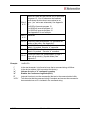
Description: Set Modes – The combination of Binary Bits specified enables additional
operating modes for the Accuriss.
Bit 0
/1n1R: Enables the Pulse Jog Mode. Jog distance
is given by “B” command, and velocity is given by
“V” command. The switch inputs becomes Jog
Inputs
Bit 1
/1n2R: Enables hardware limits. The level of the
limits is set by the “f” command.
Bit 2
/1n4R: Enables continuous jog mode.
Continuously run motor while an input switch is
closed, at a velocity set by the “V” command.
Note: Moves below zero position are possible. If
this is undesirable, use the “z” command to define
a zero position that insures that a number
underflow will not occur.
Bit 3
Bit 6
/1n8R Enables Position Correction mode. See
Appendix E.
/1n16R Enabled Overload Report Mode. See
Appendix E.
/1n32R Enable Step And Direction Mode if (1) or
enable Dual Encoder Mode if (0) E.g. /1n96R<CR>
(96=32+64) Enables step and dir mode and slaves
the motor to it. (/1?10 reads the count ) See
Appendix I.
/1n64R Enable Motor slave to encoder/step-dir.
Bit 7
/1n128R Used for Joystick mode. See Appendix F.
Bit 8
/1n256R When set, this bit will disable the
response from the drive. (future release)
Bit 4
Bit 5
USA57
Revision 1.2
40
Bits 9
& 10
Bits 11
& 12
Bit 13
Bit 14
Bit 15
Bit 16
Example:
“/”
“1”
“n”
“4”
“R”
“<CR>”
USA57
When set, these bits will execute one of the stored
programs 13, 14 or 15 whenever the feedback
shuts down the drive due to an overload or an
error. (“au” retries are exhausted). See Appendix
E.
/1n512R will execute program 13.
/1n1024R will execute program 14.
/1n1536R will execute program 15.
See Appendix E for an example..
Reserved
/1n8192R Uses potentiometer 2 to command the
motion of the motor. See Appendix F.
/1n16384R When Set, this bit will kill any move if
switch 1 is pushed. See also “d” command.
/1n32768R When Set, this bit will kill any move if
switch 2 is pushed. . See also “d” command.
/1n65536R When Set, potentiometer on Opto 2
input will set velocity. (Joystick Mode) See
Appendix F.
/1n4R<CR>
Is the start character. Lets Accuriss know that a command string will follow.
Is the device address, (this is preset at the factory).
Informs Accuriss a “n” command is coming
Enables the Continuous Jog Mode (Bit 2)
Instructs Accuriss to run the command(s) that are in the communication buffer.
Tells Accuriss that the command string is complete and causes the command to
be executed since an R is included in the command string.
Revision 1.2
41
Command:
an
Limit Switch Control
Type:
I/O
Syntax:
ann
Range:
n = 16384 or 0
Initial Value: 0
Description: Switches the end-of-travel limits on the main axis from the two opto inputs (inputs
3 & 4) to the two switch inputs (inputs 1 & 2). The second axis limits remain
unchanged at 1 &2. (Software V 6.998+)
Example:
/1an16384R<CR>
“/”
“1”
“an16384”
“R”
“<CR>”
USA57
Is the start character. Lets Accuriss know that a command string will follow.
Is the device address, (this is preset at the factory).
Informs Accuriss to switch the limit switches to inputs 1 & 2
Instructs Accuriss to run the command(s) that are in the communication
buffer.
Tells Accuriss that the command string is complete and causes the
command to be executed since an R is included in the command string.
Revision 1.2
42
Command:
b
Baud Rate
Type:
Communication Command
Syntax:
bn
Range:
n = 9570: 9570 bps
19200: 19200 bps
38400: 38400 bps
Initial Value: 9570
Description: Sets the baud rate. This command is usually stored in program zero, which is
executed on power up
Example:
/1b19200R<CR>
“/”
Is the start character. Lets Accuriss know that a command string will follow.
“1”
Is the device address, (this is preset at the factory).
“b19200” Sets the baud rate to 19200 bps
“R”
Instructs Accuriss to run the command(s) that are in the communication buffer.
“<CR>”
Tells Accuriss that the command string is complete and causes the command to
be executed since an R is included in the command string.
USA57
Revision 1.2
43
Command:
o
Type:
System Control Command
Syntax:
on
Range:
n = 0 to 3000
Microstep Waveform Correction
Initial Value: 1500
Description: Allows the user to correct any unevenness in microstep size. It is best to adjust
this with a current probe, but adjusting for lowest audible noise is a good
approximation. This command can be executed while the motor is running. Try
values very near 1500, for example, 1470.
Example:
“/”
“1”
“o1470”
“R”
“<CR>”
USA57
/1o1470R<CR>
Is the start character. Lets Accuriss know that a command string will follow.
Is the device address, (this is preset at the factory).
Sets the microstep waveform correction factor to 1470
Instructs Accuriss to run the command(s) that are in the communication buffer.
Tells Accuriss that the command string is complete and causes the command to
be executed since an R is included in the command string.
Revision 1.2
44
Command:
M
Wait for Specified Time
Type:
Program Control Command
Syntax:
Mn
Range:
n = 0 to 30000 msec
Description: M causes the command string execution to wait for the indicated time before
proceeding to the next command.
Example: /1M10000R<CR>
“/”
Is the start character. Lets Accuriss know that a command string will follow.
“1”
Is the device address, (this is preset at the factory).
“M10000” Sets wait time of 10000 msec (10 seconds)
“R”
Instructs Accuriss to run the command(s) that are in the communication buffer.
“<CR>”
Tells Accuriss that the command string is complete and causes the command to
be executed since an R is included in the command string.
USA57
Revision 1.2
45
Command:
ar
Type:
System Control Command
Syntax:
arn
Range:
n = 5073
Reset Processor
Initial Value: N/A
Description: This command will reset the processor. This reset has the same effect as cycling
the power to the Accuriss. The operand of 5073 was chosen to avoid inadvertent
resets.
Example:
“/”
“1”
“ar5073”
“R”
“<CR>”
USA57
/1ar5073R<CR>
Is the start character. Lets Accuriss know that a command string will follow.
Is the device address, (this is preset at the factory).
Performs a reset of the Accuriss
Instructs Accuriss to run the command(s) that are in the communication buffer.
Tells Accuriss that the command string is complete and causes the command to
be executed since an R is included in the command string.
Revision 1.2
46
Command:
aP
Controller Response delay
Type:
System Control Command
Syntax:
aPn
Range:
n = 0 to 3000 msec
Initial Value: 5 mec
Description: This command sets the Accuriss response delay. The Accuriss receiving the
command will respond to the master after this delay time has passed.
Example:
“/”
“1”
“aP30”
“R”
“<CR>”
USA57
/1aP30R<CR>
Is the start character. Lets Accuriss know that a command string will follow.
Is the device address, (this is preset at the factory).
Sets the Accuriss response delay to set 30 msec
Instructs Accuriss to run the command(s) that are in the communication buffer.
Tells Accuriss that the command string is complete and causes the command to
be executed since an R is included in the command string.
Revision 1.2
47
Command:
d
Type:
I/O
Syntax:
dn
Range:
n = 0 to 65000
Switch Debounce Time
Initial Value: 10
Description: Sets the minimum Kill command switch ON time for switches 1 & 2. The
debounce time is n x 50sec
Example:
“/”
“1”
“d10”
“R”
“<CR>”
USA57
/1d10R<CR>
Is the start character. Lets Accuriss know that a command string will follow.
Is the device address, (this is preset at the factory).
Sets the debounce time to 10 * 50 sec = 500 sec
Instructs Accuriss to run the command(s) that are in the communication buffer.
Tells Accuriss that the command string is complete and causes the command to
be executed since an R is included in the command string.
Revision 1.2
48
Command:
K
Backlash Compensation
Type:
System Control Command
Syntax:
Kn
Range:
n = 0 to 65000 microsteps
Initial Value: 0
Description: When a non zero value of K is specified, the drive will always approach the final
position from a direction going more negative in order to take up any backlash in
the system. If going more positive, the drive will overshoot by an amount K and
then go back. By always approaching from the same direction, the positioning will
be more repeatable.
Example:
“/”
“1”
“K7”
“R”
“<CR>”
USA57
/1K7R<CR>
Is the start character. Lets Accuriss know that a command string will follow.
Is the device address, (this is preset at the factory).
Informs Accuriss to go past the final position 7 extra microsteps prior to
reaching the final position
Instructs Accuriss to run the command(s) that are in the communication buffer.
Tells Accuriss that the command string is complete and causes the command to
be executed since an R is included in the command string.
Revision 1.2
49
Command:
aA
Type:
Motion Command
Syntax:
aAn
Range:
n = 0 to 2,147,483,648 microsteps
Oscillating (Sinusoidal) Motion Distance
Description: Sets the number of microsteps the motor will move in each direction during an
oscillating (sinusoidal) move. Any changes in this value will become valid as the
motion passes through the zero position.
Example:
/1aA51200R<CR>
“/”
“1”
“aA51200”
“R”
“<CR>”
USA57
Is the start character. Lets Accuriss know that a command string will
follow.
Is the device address, (this is preset at the factory).
Sets the oscillation distance to 51200 microsteps in each direction
Instructs Accuriss to run the command(s) that are in the communication
buffer.
Tells Accuriss that the command string is complete and causes the
command to be executed since an R is included in the command string.
Revision 1.2
50
Command:
aW
Type:
Motion Command
Syntax:
aWn
Range:
n = 0 to 2,147,483,648
Oscillating (Sinusoidal) Motion Frequency
Description: Sets the frequency of oscillation of an oscillating (sinusoidal) move. The
frequency is determined by: n * 20000/(1024 * 65536).
Example:
“/”
“1”
“aW200”
“R”
“<CR>”
USA57
/1aW51200R<CR>
Is the start character. Lets Accuriss know that a command string will follow.
Is the device address, (this is preset at the factory).
Sets the oscillation frequency to 200 * 20000/(1024 * 65536) = 0.059 hz
Instructs Accuriss to run the command(s) that are in the communication buffer.
Tells Accuriss that the command string is complete and causes the command to
be executed since an R is included in the command string.
Revision 1.2
51
Command:
J
Output Control
Type:
I/O Command
Syntax:
Jn
Range:
n = 0: No outputs ON (Binary 00)
1: Output 1 ON and output 2 OFF (Binary 01)
2: Output 1 OFF and output 2 ON (Binary 10)
3: Output 1 ON and output 2 ON (Binary 11)
Initial Value: 0
Description: Turn the system outputs ON or OFF. Enter as a 2 bit binary value.
Example:
/1J3R<CR>
“/”
Is the start character. Lets Accuriss know that a command string will follow.
“1”
Is the device address, (this is preset at the factory).
“J3”
Turns both driver outputs ON
“R”
Instructs Accuriss to run the command(s) that are in the communication buffer.
“<CR>”
Tells Accuriss that the command string is complete and causes the command to
be executed since an R is included in the command string.
USA57
Revision 1.2
52
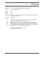
Command:
?aa
Read Back Analog to Digital Converter Values
Type:
System Control Command
Syntax:
?aa
Range:
n = N/A
Description: Reads back the values of the four (4) Analog to Digital inputs. Read back order is
channel 4,3,2,1
Example:
“/”
“1”
“?aa”
“R”
“<CR>”
/1?aaR<CR>
Is the start character. Lets Accuriss know that a command string will follow.
Is the device address, (this is preset at the factory).
Requests the value of the four Accuriss ADC inputs
Instructs Accuriss to run the command(s) that are in the communication buffer.
Tells Accuriss that the command string is complete and causes the command to
be executed since an R is included in the command string.
Response to the ?aa command looks similar to:
16256,16272,16271,16256 No Error
USA57
Revision 1.2
53
Command:
at
Analog to Digital Converter Threshold
Type:
System Control Command
Syntax:
atn
Range:
n = 100000 to 116368 (for channel 1), or
n = 200000 to 216368 (for channel 2), or
n = 300000 to 316368 (for channel 3), or
n = 400000 to 416368 (for channel 4)
Initial Value: 6144
Description: The “at” command sets the threshold, upon which a “one” or “zero” is determined
for each of the 4 channels. The Number represents the channel number followed
by a 5 digit number from 00000-16368 which represents the threshold on a scale
from a 0-3.3V. The default values are 6144 for all 4 channels which represents
1.24V.
Threshold voltage = (n/16368) * 3.3V
Changing the threshold allows the H (Halt command) and S (Skip next
command) commands to work as a variable analog input value which essentially
allows the program to act upon an analog level. This can be used, for example,
to regulate pressure to a given level, by turning a motor on/off at a given voltage.
Note: Be sure to include leading zeros, if required, to ensure that all threshold
values are 5 digits, plus the leading channel number
Example:
/1at209567R<CR>
“/”
“1”
“at204567”
“R”
“<CR>”
USA57
Is the start character. Lets Accuriss know that a command string will
follow.
Is the device address, (this is preset at the factory).
Sets the threshold of channel 2 to 9567 or 1.93V
Instructs Accuriss to run the command(s) that are in the communication
buffer.
Tells Accuriss that the command string is complete and causes the
command to be executed since an R is included in the command string.
Revision 1.2
54
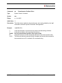
Command:
?at
Read Back Analog to Digital Threshold Values
Type:
System Control Command
Syntax:
?at
Range:
n = N/A
Description: Reads back the threshold values of the four (4) Analog to Digital inputs. Read
back order is channel 4,3,2,1
Example:
“/”
“1”
“?at”
“R”
“<CR>”
/1?atR<CR>
Is the start character. Lets Accuriss know that a command string will follow.
Is the device address, (this is preset at the factory).
Requests the value of the four Accuriss ADC input threshold values
Instructs Accuriss to run the command(s) that are in the communication buffer.
Tells Accuriss that the command string is complete and causes the command to
be executed since an R is included in the command string.
Response to the ?at command looks similar to:
6144,6144,6144,6144 No Error
USA57
Revision 1.2
55
Command:
ao
Potentiometer Position Offset
Type:
System Control Command
Syntax:
aon
Range:
n = 0 to 2000
Initial Value: 0
Description: This offset value is added to the potentiometer value “aa” multiplied by the “am”
command to obtain the position command. See Appendix F.
Example:
“/”
“1”
“ao500”
“R”
“<CR>”
USA57
/1ao500R<CR>
Is the start character. Lets Accuriss know that a command string will follow.
Is the device address, (this is preset at the factory).
Sets the potentiometer position offset value to 500
Instructs Accuriss to run the command(s) that are in the communication buffer.
Tells Accuriss that the command string is complete and causes the command to
be executed since an R is included in the command string.
Revision 1.2
56
Command:
am
Potentiometer Position Multiplier
Type:
System Control Command
Syntax:
amn
Range:
n = 0 to 20000
Initial Value: 256
Description: The potentiometer value “aa” multiplied by this value and divided by 256 equals
the position command. See Appendix F.
Example:
“/”
“1”
“am512”
“R”
“<CR>”
USA57
/1am512R<CR>
Is the start character. Lets Accuriss know that a command string will follow.
Is the device address, (this is preset at the factory).
Sets the potentiometer value multiplier to 512
Instructs Accuriss to run the command(s) that are in the communication buffer.
Tells Accuriss that the command string is complete and causes the command to
be executed since an R is included in the command string.
Revision 1.2
57
Command:
ad
Position Potentiometer Deadband Value
Type:
System Control Command
Syntax:
adn
Range:
n = 0 to 20000 microsteps
Initial Value: 50 microsteps
Description: Sets the deadband (in microsteps) on the potentiometer value which must be
exceeded before a command is issued to cause the motor to move. See
Appendix F.
Example:
“/”
“1”
“ad25”
“R”
“<CR>”
USA57
/1ad25R<CR>
Is the start character. Lets Accuriss know that a command string will follow.
Is the device address, (this is preset at the factory).
Sets the dead band value to 25 microsteps
Instructs Accuriss to run the command(s) that are in the communication buffer.
Tells Accuriss that the command string is complete and causes the command to
be executed since an R is included in the command string.
Revision 1.2
58
Command:
aC
Position Correction Mode Deadband Value
Type:
System Control Command
Syntax:
aCn
Range:
n = 0 to 65000 quadrature encoder counts
Initial Value: 50 quadrature encoder counts
Description: Sets the allowable position correction mode deadband for the coarse positioning
motion. When in position correction mode, this is the position error the motor is
allowed to be off (in quadrature encoder counts) before the motor will try to
correct itself. The “aC” value is monitored continuously while the motor is in
motion and is used to determine if the motor has been stalled. See Appendix E.
Encoder Quadrature Count= (encoder counts/rev) * 4
For example, a stepping motor is hooked up to a 400-line encoder.
Therefore, aC= 400 x 4 = 1570 quadrature encoder counts
Note: The microstep resolution must be set to the divide by 256 value “j256” in
order for correct operation of the feedback mode.
Example:
/1aC100R<CR>
“/”
Is the start character. Lets Accuriss know that a command string will follow.
“1”
Is the device address, (this is preset at the factory).
“aC100” Sets the position correction deadband value to 100 quadrature encoder
counts
“R”
Instructs Accuriss to run the command(s) that are in the communication buffer.
“<CR>”
Tells Accuriss that the command string is complete and causes the command to
be executed since an R is included in the command string.
USA57
Revision 1.2
59
Command:
aE
Encoder to Microstep Resolution Ratio Value
Type:
System Control Command
Syntax:
aEn
Range:
n = 1000 to 1,000,000
Initial Value: 1000
Description: Sets the ratio between the encoder resolution (counts/rev) and the motor
resolution (microsteps/rev). See Appendix E.
Encoder Ratio = ((motor microsteps/rev) / (encoder quadrature counts/rev)) *
1000
For example, a 1.8-degree stepping motor (running in 1/256th step mode), which
has 200x256 microsteps /rev, is hooked up to a 400-line encoder that has 1570
quadrature encoder counts.
Therefore, aE= ((200x256)/(400x4)) x 1000 = 32000
Note: The microstep resolution must be set to the divide by 256 value “j256” in
order for correct operation of the feedback mode.
Example:
/1aE32000R<CR>
“/”
“1”
“aE32000”
“R”
“<CR>”
USA57
Is the start character. Lets Accuriss know that a command string will
follow.
Is the device address, (this is preset at the factory).
Sets the encoder resolution to motor resolution ratio to value to
32000
Instructs Accuriss to run the command(s) that are in the communication
buffer.
Tells Accuriss that the command string is complete and causes the
command to be executed since an R is included in the command string.
Revision 1.2
60
Command:
au
Overload Detection Retry Limit Value
Type:
System Control Command
Syntax:
aun
Range:
n = 0 to 65000
Initial Value: 10
Description: Sets the number of times the Accuriss will retry to move the motor if a stall
condition occurs. Once the number of retries is exhausted, the motor will exit the
feedback mode report an overload error (Error 9). See Appendix E.
Note: The microstep resolution must be set to the divide by 256 value “j256” in
order for correct operation of the feedback mode.
Example:
“/”
“1”
“au25”
“R”
“<CR>”
USA57
/1au25R<CR>
Is the start character. Lets Accuriss know that a command string will follow.
Is the device address, (this is preset at the factory).
Sets the move retry value to 25 retries
Instructs Accuriss to run the command(s) that are in the communication buffer.
Tells Accuriss that the command string is complete and causes the command to
be executed since an R is included in the command string.
Revision 1.2
61
Command:
x
Fine Position Integration Period Value
Type:
System Control Command
Syntax:
xn
Range:
n = 0 to 10000
Initial Value: 10
Description: Sets the fine position mode integration value. This value is used to clear any
small remaining position error once the coarse position motion is completed. The
speed of the correction is affected by the value of the integration period. Smaller
values of “x” lead to faster corrections, but can lead to instability. See Appendix
E.
Note: The microstep resolution must be set to the divide by 256 value “j256” in
order for correct operation of the feedback mode.
Example:
“/”
“1”
“x15”
“R”
“<CR>”
USA57
/1x15R<CR>
Is the start character. Lets Accuriss know that a command string will follow.
Is the device address, (this is preset at the factory).
Sets the fine position correction integration period value to 15
Instructs Accuriss to run the command(s) that are in the communication buffer.
Tells Accuriss that the command string is complete and causes the command to
be executed since an R is included in the command string.
Revision 1.2
62
Command:
ac
Fine Position Final Error Range Value
Type:
System Control Command
Syntax:
acn
Range:
n = 0 to 65000 quadrature encoder counts
Initial Value: 50 quadrature encoder counts
Description: Sets the allowable position correction mode deadband for the fine positioning
motion. When in position correction mode, this is the final position error the motor
is allowed to be off (in quadrature encoder counts) before the motor stops tring to
correct itself. See Appendix E.
Encoder Quadrature Count= (encoder counts/rev) * 4
For example, a stepping motor is hooked up to a 400-line encoder.
Therefore, aC= 400 x 4 = 1570 quadrature encoder counts
Note: The microstep resolution must be set to the divide by 256 value “j256” in
order for correct operation of the feedback mode.
Example:
“/”
“1”
“ac25”
“R”
“<CR>”
USA57
/1ac25R<CR>
Is the start character. Lets Accuriss know that a command string will follow.
Is the device address, (this is preset at the factory).
Sets the fine position final deadband value to 25 quadrature encoder
counts
Instructs Accuriss to run the command(s) that are in the communication buffer.
Tells Accuriss that the command string is complete and causes the command to
be executed since an R is included in the command string.
Revision 1.2
63
Command:
u
Error Recovery Retry Limit Value
Type:
System Control Command
Syntax:
un
Range:
n = 0 to 65000
Initial Value: 0
Description: Sets the number of times error recovery scripts 13, 14, or 15 are run prior to
calling upon final recovery script 12. See Appendix E.
Note: The microstep resolution must be set to the divide by 256 value “j256” in
order for correct operation of the feedback mode.
Example:
“/”
“1”
“u5”
“R”
“<CR>”
USA57
/1u5R<CR>
Is the start character. Lets Accuriss know that a command string will follow.
Is the device address, (this is preset at the factory).
Sets the error recovery script retry value to 5 attempts
Instructs Accuriss to run the command(s) that are in the communication buffer.
Tells Accuriss that the command string is complete and causes the command to
be executed since an R is included in the command string.
Revision 1.2
64
Command:
T
Terminate Command or Loop
Type:
System Control Command
Syntax:
T
Range:
None
Description: Terminate current command or loop.
Example:
“/”
“1”
“T”
“<CR>”
USA57
/1T<CR>
Is the start character. Lets Accuriss know that a command string will follow.
Is the device address, (this is preset at the factory).
Terminates the current command string
Tells Accuriss that the command string is complete and causes the command to
be executed since an R is included in the command string.
Revision 1.2
65
Command:
?0
Report Current Commanded Position
Type:
System Status Command
Syntax:
?0
Range:
0
Description: Returns the current position of the commanded motor.
Example:
“/”
“1”
“?0”
“<CR>”
USA57
/1?0<CR>
Is the start character. Lets Accuriss know that a command string will follow.
Is the device address, (this is preset at the factory).
Report current commanded position
Tells Accuriss that the command string is complete.
Revision 1.2
66
Command:
?2
Report Current Maximum Speed
Type:
System Status Command
Syntax:
?2
Range:
2
Description: Returns the current Slew/Max speed for Position mode of the commanded motor.
Example:
“/”
“1”
“?2”
“<CR>”
USA57
/1?2<CR>
Is the start character. Lets Accuriss know that a command string will follow.
Is the device address, (this is preset at the factory).
Report current running speed
Tells Accuriss that the command string is complete.
Revision 1.2
67
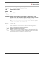
Command:
?4
Report Input Status
Type:
System Status Command
Syntax:
?4
Range:
0 to 15
Description: Returns the status of all four inputs in 4 bit binary format, 0 to15, of the
commanded motor.
Input
Switch 1
Switch 2
Opto 1
Opto 2
Example:
“/”
“1”
“?4”
“<CR>”
USA57
Contribution to ?4 response if active
1
2
4
8
/1?4<CR>
Is the start character. Lets Accuriss know that a command string will follow.
Is the device address, (this is preset at the factory).
Report current input status
Tells Accuriss that the command string is complete.
Revision 1.2
68
Command:
?6
Report Current Microstep Size
Type:
System Status Command
Syntax:
?6
Range:
1, 2, 4, 8 microsteps per full step
Description: Returns the current microstep size of the commanded motor.
Example:
“/”
“1”
“?6”
“<CR>”
USA57
/1?6<CR>
Is the start character. Lets Accuriss know that a command string will follow.
Is the device address, (this is preset at the factory).
Report the current microstep size
Tells Accuriss that the command string is complete.
Revision 1.2
69
Command:
?9
Erase EEPROM
Type:
System Control Command
Syntax:
?9
Range:
N/A
Description: Erases all commands in the EEPROM of the commanded motor.
Example:
“/”
“1”
“?9”
“<CR>”
USA57
/1?9<CR>
Is the start character. Lets Accuriss know that a command string will follow.
Is the device address, (this is preset at the factory).
Erases the system’s EEPROM
Tells Accuriss that the command string is complete.
Revision 1.2
70
Command:
?10
Second Encoder (n = 0) or Step & Direction (n = 32) Input Count
Type:
System Status Command
Syntax:
?10
Range:
N/A
Initial Value: N/A
Description: Requests the second encoder (n = 0) or step & direction (n = 32) input count
value.
Example:
“/”
“1”
“?10”
“<CR>”
USA57
/1?10<CR>
Is the start character. Lets Accuriss know that a command string will follow.
Is the device address, (this is preset at the factory).
Requests the second encoder or step & direction input count
Tells Accuriss that the command string is complete.
Revision 1.2
71
Command:
&
Return Firmware Version
Type:
System Status Command
Syntax:
&
Range:
None
Description: Requests firmware version of the commanded motor.
Example:
“/”
“1”
“&”
“<CR>”
USA57
/1&<CR>
Is the start character. Lets Accuriss know that a command string will follow.
Is the device address, (this is preset at the factory).
Requests firmware revision
Tells Accuriss that the command string is complete.
Revision 1.2
72
Command:
Q
Status Request
Type:
System Status Command
Syntax:
Q
Range:
0 to 3
0: No error
1: Initialization error
2: Invalid Command
3: Operand out of range
Description: Query the Accuriss for its current status.
Returns the Ready/Busy status as well as any error conditions in the “Status”
byte of the return string. The return string consists of the start character (/), the
master address (0) and the status byte. Bit 5 of the status byte is set when the
Accuriss is ready to accept commands. It is cleared when the Accuriss is busy.
The least significant four bits of the status byte contain the completion code.
Errors in OpCode will be returned immediately, when errors in Operand range
will be returned only when the next command is issued. See Appendix B
Example:
“/”
“1”
“Q”
“<CR>”
USA57
/1Q<CR>
Is the start character. Lets Accuriss know that a command string will follow.
Is the device address, (this is preset at the factory).
Requests Accuriss status
Tells Accuriss that the command string is complete.
Revision 1.2
73
Command:
$
Status Request
Type:
System Status Command
Syntax:
$
Range:
N/A
Description: Returns the currently executing command string
Example:
/1$<CR>
“/”
“1”
“$”
“<CR>”
USA57
Is the start character. Lets Accuriss know that a command string will follow.
Is the device address, (this is preset at the factory).
Returns the command string currently be executed
Tells Accuriss that the command string is complete.
Revision 1.2
74
Programming Examples
Example #1 (Move to an Absolute Position of 12345 steps)
/1A12345R<CR>
This breaks down to:
“/”
Is the start character. Lets Accuriss know that a command string will follow.
“1”
Is the device address, (this is preset at the factory).
“A12345” Causes the motor turn to an Absolute position 12345 steps
“R”
Instructs Accuriss to run the command(s) that are in the communication buffer.
“<CR>”
Tells Accuriss that the command string is complete and causes the command to
be executed since an R is included in the command string.
Note: HyperTerminal issues each character as you type it in. Therefore, it is not possible to cut
and paste in HyperTerminal. Backspace is allowed only up to the address character. If
backspace is used, all characters “backspaced” must be retyped in. If a typing error is made,
typically hit enter and type it all in again – what was typed in will be overwritten as long as the R
command at the end was not present.
Example #2 (Loop absolute moves with a wait in between)
/1gA1000M500A0M500G10R<CR>
This breaks down to:
“/”
Is the start character. Lets Accuriss know that a command string will follow.
“1”
Is the device address, (this is preset at the factory).
“g”
Indicates the start of a loop block
“A1000” Causes the motor move to the Absolute position of 1000 steps
“M500”
Causes the Accuriss to wait for 500 Milliseconds.
“A0”
Makes the motor turn to Absolute position 0.
“M500”
Is another wait command of 500 Milliseconds.
“G10”
Will make all commands between here and starting location of the small “g”
repeat 10 times
“R”
Instructs Accuriss to run the command(s) that are in the communication buffer.
“<CR>” Tells Accuriss that the command string is complete and causes the command to
be executed since an R is included in the command string.
To terminate the above loop while in progress type “/1T”.
USA57
Revision 1.2
75
Example #3 (Program Storage and Recall)
This example stores a command string to storage location #2 for later execution:
/1s2gA10000M500A0M500G10R<CR>
This breaks down to:
“/”
“1”
“s2”
“g”
“A1000”
“M500”
“A0”
“M500”
“G10”
“R”
“<CR>”
Is the start character. Lets Accuriss know that a command string will follow.
Is the device address, (this is preset at the factory).
Tells Accuriss to store the command string that follows to storage locations #2
Indicates the start of a loop block
Causes the motor move to the Absolute position of 1000 steps
Causes the Accuriss to wait for 500 Milliseconds.
Makes the motor turn to Absolute position 0.
Is another wait command of 500 Milliseconds.
Will make all commands between here and starting location of the small “g”
repeat 10 times
Instructs Accuriss to run the command(s) that are in the communication buffer.
Tells Accuriss that the command string is complete and causes the command to
be executed since an R is included in the command string.
(Note: program 0 is always executed on power up, if we had used storage location 0 instead of
storage location 2 in the above example, then this program would execute automatically on
power up).
This example executes the command string stored in the above example.
/1e2R<CR>
This breaks down to:
“/”
“1”
“e2”
“R”
“<CR>”
USA57
Is the start character. Lets Accuriss know that a command string will follow.
Is the device address, (this is preset at the factory).
Instructs the Accuriss to execute the command string in storage location #2.
Instructs Accuriss to run the command(s) that are in the communication buffer.
Tells Accuriss that the command string is complete and causes the command to
be executed since an R is included in the command string.
Revision 1.2
76
Example #4 (Set move and hold Current values, Wait for Switch 2 closure then Home to
Opto #1)
/1s0m75h10gJ3M500J0M500G10HZ10000A1000A0R<CR>
This breaks down to:
“/”
“1”
“s0”
Is the start character. Lets Accuriss know that a command string will follow.
Is the device address, (this is preset at the factory).
Stores the command string that follows in storage location #0 (command strings
stored in storage location #0 are executed on power up).
“m75”
Sets the move current to 75% of max
“h10”
Sets the hold current to 10% of max
“g”
Start a loop block
“J3”
Turns ON both driver outputs.
“M500”
Wait 500 msec
“J0”
Turn OFF both driver outputs.
“M500”
Wait 500 msec
“G10”
Will make all commands between here and starting location of the small “g”
repeat 10 times
“H”
Waits for a switch 2 closure. (Switch 2 is automatically selected since no number
was specified)
“Z10000” Home the stepping motor to opto #1. Maximum steps allowed to find opto #1 =
10000 steps.
“A1000” Move to absolute position 1000
“A0”
Move to absolute position 0
“R”
Instructs Accuriss to run the command(s) that are in the communication buffer.
“<CR>” Tells Accuriss that the command string is complete and causes the command to
be executed since an R is included in the command string.
Note: This program string will abort after the “Z10000” command if it does not find a flag.
USA57
Revision 1.2
77
Example #5 (Nested loop example)
/1gA100A1000gA100A10G10G100R<CR>
This breaks down to:
“/”
“1”
“g”
“A100”
“A1000”
“g”
“A100”
“A10”
“G10”
G100
“R”
“<CR>”
Is the start character. Lets Accuriss know that a command string will follow.
Is the device address, (this is preset at the factory).
Start an outer loop block
Go to Absolute position 100
Go to Absolute position 1000.
Start an inner loop block.
Go to Absolute position 100.
Go to Absolute position 10.
Repeat inner loop block 10 times. (End of Inner Loop)
Repeat outer loop block 100 times. (End of outer loop)
Instructs Accuriss to run the command(s) that are in the communication buffer.
Tells Accuriss that the command string is complete and causes the command to
be executed since an R is included in the command string.
To terminate either of the above loops while in progress type “/1T”.
USA57
Revision 1.2
78
Example #6 (Skip / Branch instruction)
/1s0gA0A1000S13e1G0R<CR>
/1s1gA0A100S03e0G0R<CR>
Two “Programs” are stored in storage locations 0 and 1, respectively, and the code in these
programs switches from one program to the other depending on the state of input #3. In the
example below, the code will cycle the motor between position A0 and A1000 if input #3 is High
and between A0 and A100 if input #3 is Low.
Stored command string 0: /1s0gA0A1000S13e1G0R<CR>
This breaks down to:
“/”
“1”
“s0”
“g”
“A0”
“A1000”
“S13”
“e1”
“G0”
“R”
“<CR>”
Is the start character. Lets Accuriss know that a command string will follow.
Is the device address, (this is preset at the factory).
Store command string that follows to storage location #0 (executed on power up).
Start loop block
Go to Absolute position 0
Go to Absolute position 1000.
Skip next instruction if input # 3 is High
Execute (Jump to) command string in storage location #1
End of loop block (infinite loop since value is 0).
Instructs Accuriss to run the command(s) that are in the communication buffer.
Tells Accuriss that the command string is complete and causes the command to
be executed since an R is included in the command string.
Stored command string 1: /1s1gA0A100S03e0G0R<CR>
This breaks down to:
“/”
“1”
“g”
“A0”
“A1000”
“S03”
“e0”
“G0”
“R”
“<CR>”
USA57
Is the start character. Lets Accuriss know that a command string will follow.
Is the device address, (this is preset at the factory).
Start loop block
Go to Absolute position 0
Go to Absolute position 100.
Skip next instruction if input 3 is Low
Execute (Jump to) command string in storage location #0
End of loop block (infinite loop since value is 0).
Instructs Accuriss to run the command(s) that are in the communication buffer.
Tells Accuriss that the command string is complete and causes the command to
be executed since an R is included in the command string.
Revision 1.2
79
Appendix A
Homing Algorithm in Detail
The “Z” command is used to move the motor to a known position by seeking a home sensor.
When issued, the motor will turn toward the 0 position until the home opto-sensor is interrupted.
If the home sensor is already interrupted, the motor will back off of the sensor in the opposite
direction and then come back in until the home sensor is re-interrupted. The motor position
counter is set to zero. The homing motion is done at the current speed “V”. The maximum
number of steps allowed to go towards home without encountering the sensor is defined by the
Z command operand (n) + 400 steps. The maximum number of steps away from home (while
sensor is cut) is 10000 steps.
To set up the home flags:
First ensure that a positive move e.g. /1P100R moves away from home and the home flag. If
motor does not go away from home, flip the connections to only one of the windings of the
stepper.
The Default condition expects the output of the Home flag to be low when away from the home
sensor (as is the case in an opto). If the Home flag is high when away from the home sensor
(as in the case of a “Normally Open” switch) then issue the command /1f1R to reverse the
polarity that is expected of the home flag.
Issue the command e.g. /1Z100000R or /1f1Z100000R as necessary.
Homing should be done at a slow speed, especially if homing to a narrow Index pulse on an
encoder, which may be missed at high speeds.
The home opto sensor and flag should be set up to be unambiguous, i.e. when motor is all the
way at one end of travel, the flag should interrupt the home opto sensor. When at other end of
travel, the flag should not interrupt the home opto sensor. There should only be one High to Low
transition possible in the whole range of travel. A Homing routine can be done to either an opto
sensor (N1 Mode) or to an Index Pulse (N2 Mode).
The Main axis homes to opto1 (input #3). This opto is also the lower limit.
The Main axis uses opto 2 (input #4) as its upper limit.
Note that limits are engaged by the command “/1n2R “ (lower case “n”). The default (n0) mode
does not check the limits when moving.
Default “f” mode (f0) expects the inputs to be Low when the axis is away from the limits/home.
The command “/1f1R” reverses this.
USA57
Revision 1.2
80
Also the opto sensors and switches are interchangeable. If four opto sensors are desired, power
for the extra opto sensors can be drawn from the 5V supply on the encoder connector. These
extra opto sensors may require an external resistor in series with the LED. When connecting
any external switches, connect them between any input and ground.
Main Axis Homing Details:
There are four full steps in a single electrical cycle that moves the stepping motor. (A+, B+, A-,
B-). For repeatability in homing, the home position is set to first step in that cycle (A+) that
occurs after the flag edge has been seen. (This means that the home position is defined some
ways beyond the middle of the flag).
However, there is a small but finite chance that an ambiguity in home position may occur in the
rare case that the exact point of switching into A+ occurs at the same point at which the flag is
interrupted. In the case where a 4 step ambiguity in home position may exist because the flag
may sometimes be interrupted just before and sometimes just after, the procedure below
describes a method by which the ambiguity can be removed. However, this procedure need not
be followed if a 4 step inaccuracy in Home position is acceptable.
To eliminate the home position ambiguity, first issue the Z command, allow the motor to home.
Then move 2 full steps (in any direction), now mechanically move the flag edge (or sensor) such
that it trips in the middle of the sensor by adjusting it while watching the status LED on the board
which shows the status of the home sensor. This will ensure that the flag trips at A- and thus the
motor will home to a unique position of A+.
Another way to do this, if it is not hazardous, is to put the motor in an endless homing loop
“/1gZ10000GR”, then move the flag/opto around while the motor is homing. It will be noticed
that the motor will home to two distinct positions that are 4 steps apart. Make sure the High to
Low transition point of the Opto sensor is NOT near these positions (exact position does not
matter as long as it is not near the place where it homes to).
Second Axis Homing Details:
The second axis will home to the exact transition of the home flag, and does not seek a Phase
A zero. The second axis uses the switch inputs for homing and limits.
Manual homing:
Motors can be manually homed to any input by the use of a polling loop such as:
/1s1z0R Set the current position to zero and store to storage location #1
/1z100000gD1S04e1GR Move backwards in an endless loop until input #4 goes High .
USA57
Revision 1.2
81
Homing to a hard stop:
It is possible to send the motor against a hard stop and then force the position counter to zero or
some other value as necessary. The command string “/1z0R” zeros the position counter. The
command string “/1z333R” will set the position to 333, etc.
USA57
Revision 1.2
82
Appendix B
Device Response Packet
The Accuriss responds to commands by sending messages addressed to the “Master Device”.
The Master Device (which for example is a PC) is assumed to always have Address zero. The
master device should parse the communications on the bus continuously for responses starting
with /0. (Do NOT, for example, look for the next character coming back after issuing a
command because glitches on the bus when the bus reverses direction can sometimes be
interpreted as characters)
After the /0, the next piece of information is the “Status Character” which is actually a collection
of 8 bits.
These Bits are:
Bit7 … Reserved
Bit6 … Always Set
Bit5 … Ready Bit - Set when Accuriss is ready to accept a command.
Bit4 … Reserved
Bits 3 thru 0 form an error code from 0-15
0 = No Error
1 = InitError
2 = Bad Command (illegal command was sent)
3 = Bad Operand (Out of range operand value)
4 = N/A
5 = Communications Error (Internal communications error)
6 = N/A
7 = Not Initialized (Controller was not initialized before attempting a move)
8 = N/A
9 = Overload Error (Physical system could not keep up with commanded position)
10 = N/A
11 = Move Not Allowed
12 = N/A
13 = N/A
14 = N/A
15 = Command Overflow (unit was already executing a command when another command was
received)
Note that RS485 Bus devices must respond right away, after the master sends a command,
before the success or failure of the execution of the command is known. Due to this reason
some error messages that come back are for the previous command, for example, “failure to
find home”.
USA57
Revision 1.2
83
A program that receives these responses must continuously parse for /0 and take the response
from the bytes that follow the /0. The first Character that comes back may be corrupted due to
line turn around transients, and should not be used as a “timing mark”.
USA57
Revision 1.2
84
Example Initialization Error Response:
Note that the Upper Nibble only typically takes on values of 4 or 6 (Hex)
An initialization error has response has 1 in the lower Nibble. So the response is 41 Hex or 61
Hex, which corresponds to ASCII character upper case “A” or lower case “a”, depending on if
the device is busy or not.
Example Invalid Command Response:
Note that the Upper Nibble only typically takes on values of 4 or 6 (Hex)
An invalid command has response has 2 in the lower Nibble. So the response is 42 Hex or 62
Hex, which corresponds to ASCII character upper case “B” or lower case “b”, depending on if
the device is busy or not.
Example Operand Out of range Response:
Note that the Upper Nibble only typically takes on values of 4 or 6 (Hex)
An operand out of range has response has 3 in the lower Nibble. So the response is 43 Hex or
63 Hex, which corresponds to ASCII character upper case “C” or lower case “c”, depending on
if the device is busy or not.
Example Overload Error Response:
Note that the Upper Nibble only typically takes on values of 4 or 6 (Hex)
An overload error has response has 7 in the lower Nibble. So the response is 47 Hex or 67 Hex,
which corresponds to ASCII character upper case “I” or lower case “i”, depending on if the
device is busy or not.
Example Response to command /1?4
FFh: RS485 line turn around character. It’s transmitted at the beginning of a message.
2Fh: ASCII “/”Start character. The DT protocol uses the ‘/’ for this.
30h: ASCII “0” This is the address of the recipient for the message.
In this case ASCII zero (30h) represents the master controller.
57h: This is the status character (as explained above
31h:
31h: These two bytes are the actual answer in ASCII.
This is an eleven which represents the status of the four inputs.
The inputs form a four bit value. The weighting of the bits is:
Bit 0 = Switch 1
Bit 1 = Switch 2
Bit 2 = Opto 1
Bit 3 = Opto 2
03h: This is the ETX or end of text character. It is at the end of the answer string.
0Dh: This is the carriage return…
0Ah: ...and line feed.
USA57
Revision 1.2
85
Command Response Modification
Requires Firmware Revision 7.08+
Note that it is possible to change the response from the device to include device address and
other parameters such as current position.
/1Q1<CR> will modify every subsequent response to include the device address
/1Q2<CR> will modify every subsequent response to include the current position
If more than one command is used then both parameters will be reported back with a comma
delimited response.
USA57
Revision 1.2
86
Appendix C
Heat Dissipation
Most stepper applications require intermittent moving of the motor. In the Accuriss, the current is
increased to the “move” current, the move is performed, and the current is then reduced to the
“hold” current automatically. The heat dissipation in the drive is proportional to the current
flowing in the drive and, therefore, the dissipation occurs primarily during the “move”.
When the Drive generates heat, the heat first warms the circuit board and housing.
Only then does the heat transfer to the surroundings. For intermittent moves that are less than
one minute in duration, the Drive primarily cools using this thermal inertia of the board and
housing, and not by steady state dissipation to the surrounding ambient.
The electronics for the Accuriss are fully capable of running at the rated voltage and current.
However, due to the small size of the boards, which limits the steady state heat transfer to the
ambient, care must be taken when the drive is used in high duty cycle and/or high current
applications. For conservative operation, it is recommended that the duty cycle be reduced
linearly, from 100% duty at 50% of rated current, to 25% duty at 100% of rated current. (Duty
cycle means the percentage of the time that the drive is moving the load – averaged over 5
minutes). Conservatively, the maximum continuous run at 100% current is about 1 minute. An
on board thermal cutout typically trips after about 2 minutes at 100% current. (This cutout is selfresetting when the drive cools). Of course, at 50% of current, the drive will run continuously with
no time limit.
Most “intermittent move” applications will NOT require derating of the drive.
In case the Accuriss is required to run 100% of the time at 100% current, forced air cooling or
mounting to an aluminum structure is required.
Accuriss drives are designed with parts rated at 85°C or better. This means the PCB copper
temperature must remain below 85°C. The ambient air temperature allowed depends on the
airflow conditions.
MTBF is 20000Hrs at 85°C PCB copper temperature and doubles for every 10°C lower
than 85°C.
USA57
Revision 1.2
87
Appendix D
Step Loss Detection using an Opto-sensor
For some applications, which operate without encoder feedback, it may be necessary to detect
loss of steps due to the mechanism stalling for any reason.
Step loss is easily detected by following the algorithm below:
1. Home the stepper to the opto using the Z Command.
2. Move out of the flag a little by issuing, for example, an A100 command.
3. Figure out the exact step on which the flag gets cut by issuing D1 commands followed
by /1?4 commands to read back the opto. Let’s call this value i. (This only needs to be
done once during initial setup).
4. Execute the move sequence for which step loss detection is needed.
5. Issue a command to go back to absolute position Y+1.
6. Check the opto; it should not be cut (read opto back with the /1?4 command).
7. Now issue a command to go to position Y-1.
8. Check the opto; it should be cut (read opto back with the /1?4 command).
9. If the opto was not at the state expected, steps may have been lost.
NOTE: Step loss detection can also be done by looking for changes on the other inputs.
USA57
Revision 1.2
88
Appendix E
Position Correction Mode and Overload Report Mode
Position Correction Mode (Software version 6.7 or higher)
Position correction mode, when enabled, will move until the encoder reads the correct number.
Once enabled, positions are given in quadrature encoder counts of the encoder (not in
microsteps). If the motor stalls during a move, the mode will re-attempt the move until the
encoder reads the correct number. This algorithm runs while the stepper is in motion and will
detect a stalled motor during a move.
There are two main types of feedback methods:
1. The first method is to place the encoder on the motor shaft.
2. The second method is to place the encoder on the component that is closest to the
actual item being positioned, and may be only be loosely coupled to the motor due to
backlash etc.
The Accuriss will work with either feedback method.
Setting Up Encoder Feedback
1. Set the encoder ratio “aE”.
NOTE: the encoder ratio should be changed when at the zero position for best performance.
Encoder Ratio = (microsteps/rev divided by quadrature encoder counts/rev) x 1000.
The encoder ratio must preferably be a whole number after the multiply by 1000. (If this is not a
whole number, see discussion further down).
The motor must be left in 256th microstep mode for correct operation of feedback mode.
For example, a 1.8-degree stepper (running in 1/256th step mode), which has 200x256
microsteps /rev, is hooked up to a 400-line encoder that has 1570 quadrature encoder counts.
aE= ((200x256)/(400x4)) x1000=32000
Issue the command /1aE32000R to set this encoder ratio.
NOTE: If the encoder ratio is unknown, do the following:
1. Leave the encoder ratio at its power-up default of 1000.
2. Ensure that the encoder increases its count when the motor moves in the positive
direction. If not, switch the A & B output lines of the encoder, which will reverse the count
USA57
Revision 1.2
89
3.
4.
5.
6.
7.
8.
9.
direction; or switch the wires to one of the windings on the stepper motor, which will
reverse the direction of rotation (do not use the F command).
Issue a “/1n0R” command to clear any special modes.
Issue a “/1z0R” command, which will zero both the encoder position and step position.
Issue “/1A100000R” command and ensure that the move completes at a velocity that does
not cause the motor to stall.
Issue a “/1?0” command, which reads back the current position. This current position value
should be 100000.
Issue a “/1?8” command, which reads back the encoder position.
Issue a “/1aE0R” command, which auto divides these two numbers.
Issue a “/1?aE” command, which reads back the encoder ratio computed.
This value read-back is only a rough guide, and will be off by a few counts due to
inaccuracies in the motor position and run-out in the encoder.
NOTE: The value read-back MUST be overwritten by the EXACT value that represents ratio.
10. Issue a “/1aE32000R” command, or whichever exact number represents the encoder ratio.
2. (Optional) Set the error in quadrature encoder counts allowed before a correction is
issued.
E.g. /1aC50R (default is 50)
3. (Optional) Set the Overload Timeout Value.
This is the number of retries allowed under a stall condition.
E.g. /1au10000R (default is 100)
4. Enable the feedback mode.
1.
Zero positions just prior to enabling feedback mode by issuing a “/1z0R” command. (Or issue
/1z10000R etc. if you need to at this time.)
Enable position correction mode by issuing a “/1n8R” command.
Example (Software version V6.7 or higher):
/1z0aC50h40m40au100aE32000V1000n8R starts the position correction mode, where:
“/”
“1”
“z0”
“aC50”
“h40”
“m40”
“au100”
“aE32000”
USA57
Is the start character. Lets Accuriss know that a command string will
follow.
Is the device address, (this is preset at the factory).
Set the current position to zero
Set the allowable step error band to 50 microsteps
Set maximum hold current to 40%
Set maximum run current to 40%
Set the overload detection retry count to 100
Set the encoder to microstep resolution ratio to 32000
Revision 1.2
90
“V1000”
“n8”
“R”
Set speed of motor to 1000 microsteps per second
Enables the position correction mode
Instructs Accuriss to run the command(s) that are in the communication
buffer.
Fine position correction (V6.99+)
When in n8 mode, there are two position correction algorithms:
The COARSE ALGHORITHM, as described above, operates to bring the motors to within the
value given by “aC” (upper case C). ). This algorithm runs all the time (while the stepper is in
motion) and will detect a motor that is stalled or lagging by more than the value of “aC” during
a move. When a problem is detected, the axis will stop and reissue a move starting from zero
velocity so as to slowly spin up motor that may have stalled at high speed.
In firmware version 6.99+, a fine position correction integrator algorithm (FINE ALGORITHM )
is engaged once the major move is completed to zero out any small residual position error.
The speed of this correction is affected by the “x” integration period value. /1x10R is default.
Smaller values of x correct faster but may lead to oscillations, e.g., /1x3R. The fine position
correction deadband is set by “ac” (lower case c) E.g.: /1ac10R, the default ac is 20 encoder
counts. This can be adjusted down to zero, if desired but it may take time to settle depending
on system stiction and backlash, especially if the encoder is decoupled from the motor. The
integration algorithm runs at the hold current value, and this may need to be adjusted to a
reasonably high number, depending on the load. It is also best to run at a hold current equal
to the move current so that the motor does not “relax” and move to a detent position at the
end of the move. The move complete (non busy) signal will be asserted when the move
completes to within “ac” for the first time. Subsequent disturbances greater than “ac” but less
than “aC” will be corrected by the fine correction algorithm and will not be reported as “busy”.
Only disturbances greater than “aC” will result in the coarse correction algorithm being
engaged and the busy signal being asserted.
Example: (V6.99+) /1z0aC50ac10x10h40m40au100aE32000n8R
“/”
“1”
“z0”
“aC50”
“ac10”
“h40”
“m400”
“au100”
“aE3200”
“n8”
“R”
USA57
Is the start character. Lets Accuriss know that a command string will
follow.
Is the device address, (this is preset at the factory).
Set the current position to zero
Set the allowable step error band to 50 microsteps
Set maximum hold current to 40%
Set maximum run current to 40%
Set the overload detection retry count to 100
Set the encoder to microstep resolution ratio to 32000
Enables the position correction mode
Instructs Accuriss to run the command(s) that are in the communication
buffer.
Revision 1.2
91
Notes On Feedback Mode
If motor consistently stops during a move:
If a very fine line count encoder is used such that, for example, the encoder ratio is around
2000, or if the encoder is decoupled from the motor shaft, or if the encoder ratio has some
fractional component and is non integer, increase the error (aC) allowed for the coarse
algorithm. For example set aC to 2000. This way a move that is in progress will not be halted
and restarted because the coarse algorithm has detected that the following error is too large.
Instead, the move will complete with some error, and the fine algorithm integrator will null out
the error to within the lower case “ac” value at the end of the move.
Busy/Non Busy Status:
The status will read busy until any move is reached to within the “ac” value; however, once a
move is complete any subsequent disturbance is handled by the fine integrator as long as it is
less than “aC” (upper-case C). These subsequent corrections by the fine algorithm will not
read busy; however, if the error becomes greater than “aC” the deadband reckoning algorithm
is turned on, and a formal correction move is initiated. This move changes the drive status to
busy, and no external commands will then be accepted. It is important to set the coarse
deadband reckoning (aC value) to a reasonable number (for example, 50) or else the drive will
always be attempting to correct.
Other Notes
When position correction mode is enabled (/1n8R) the drive will keep retrying any stalled
moves until the number of “au” retries are exhausted, and will NOT halt any strings or loops
upon detection of a stall.
During position correction mode, the “/1T” command will halt any move, but there is a
possibility that the drive may instantly reissue itself a position correction command, especially
if it is fighting a constant disturbance. It may be necessary to issue a “/1n0R” command to
positively halt a move in progress.
If the encoder ratio is changed from its default of 1000, the allowed max position will be
decreased from +2,147,483,648 by the same ratio. The max position counter will rollover from
positive to negative range when this limit is exceeded.
Do not use the upper case “F” (reverse direction) command when using encoder feedback
mode. Instead, switch the encoder AB lines or the lead wires to one phase of the motor.
Jog mode will not work with encoder feedback on
Arbitrary Measurement Units
It is not necessary to use feedback mode or even have an encoder, in order to set the encoder
ratio /1aE32000R etc. Setting the encoder ratio thus allows positioning in any units of the user’s
choice.
USA57
Revision 1.2
92
Overload Report Mode
In n8 feedback mode, the drive will automatically correct any stalled moves up to the limit given
by the “au” command. Only then will it report Error 9 of an overload.
However, it may be desirable to detect a stall but not correct it. The n16 mode does just this.
The encoder value is continuously compared against the commanded position and Error 9 is set
when these do not match to within the error band specified by the “aC” command. When this
error occurs, the drive will exit from any loops or remaining command strings it may be
executing.
The overload report mode is enabled by the /1n16R command, and requires the encoder ratio to
be entered correctly via the “aE” command. Issue /1zR to zero both the encoder and position
counter just prior to issuing /1n16R command string.
When an overload occurs, the drive can be set to execute stored strings 13, 14, or 15. See auto
recovery scripts below.
Auto Recovery in Feedback Mode
Auto Recovery Scripts (Available in V6.997+)
In n8 mode, the Accuriss determines a stalled or overload condition by checking to see if the
encoder is tracking the commanded trajectory. If the encoder is not following the commanded
trajectory within the error specified by “ac”, a number of retries given by the “au” command are
executed.
When an overload condition is detected (retry counter has exceeded the “au” value), it will be
reported back as an upper or lower case I (Error 9) when the status is queried. This status can
be used by an external computer to execute a recovery script.
However, it may be desired that the drive recover by itself in the case of a stand-alone
application. For this purpose, the “n” mode bits n512 and n1024 can be used.
It is necessary to combine these bits with n8 so, for example, n512+n8 = n520.
Depending on which of these bits is set, the Accuriss will execute stored program 13, 14 or 15
when an overload is detected. Program 12 is also executed as a last resort, if programs 13, 14,
or 15 cannot auto recover after retrying the number of times given by the “au” command.
NOTE: an overload error on any motor, if enabled, will execute error recovery.
Example:
1. Enter /1s13p1202n520R. This sets error recovery script to send “1202” on every
recovery.
/1s12p1201R sets final script to send “1201.”
2. Enter /1aM1m5h5z0aC50au5u3aE12800L100n520R. This sets h= 5 and m=5 so that we
can stall the motor easily.
3. Setup encoder ratio as appropriate: /1aE32000R etc.
USA57
Revision 1.2
93
4.
5.
6.
7.
8.
9.
Zero Encoder and Position Counter /1z0R
Set au = 5 so that 5 retries max are allowed
Set u = 5 so that program 13 is run a maximum of 3 times.
Set n =520 = n8 + n512 so that stored program 13 will be issued on error condition.
Now move the motor shaft so that the motor tries to correct 5 times and then gives up.
After the 5th retry the motor will execute stored program 13 and will attempt to send a
“1202” on the 485 bus. Then the feedback turns on and 5 more tries are made. If the motor
is held stalled, the “1202” will be sent 32 times followed by a “1201” as the final recovery
script, stored program 12, is run.
Typical reasons that the following error is too great:
“m” value (current) set too low.
“L” value (acceleration) set too high for torque available from motor.
“V” value (velocity) set too high for torque available from motor.
Physical obstruction, or excessive friction.
USA57
Revision 1.2
94
Appendix F
Analog Inputs and Analog Feedback
Analog Inputs
The four inputs of the Accuriss are all ADC inputs.
The ADC values can be read via RS485, E.g., /1?aa<CR>. These values are on a scale
of 0-16368 as the input varies from 0-3.3V. The inputs as shipped are good to about 7
bits resolution, but can be made to be better than 10 bits with the removal of the input
overvoltage protection circuitry (call factory for details).
The threshold upon which a digital “one” or “zero” is called can be varied with the “at”
command and affect the Halt H command or Skip S command.
Example:
Enter /1at309999R<CR>. This sets the threshold on input 3 to 09999. Note that it is
necessary to insert leading zeros after the input number (3), since the threshold value
must always be entered as five digits (00000-16368).
The thresholds for all four inputs can be read back with the /1?at<CR> command. The
Accuriss has a default threshold value of 6144 (1.24V).
It is possible, for example, to regulate pressure by turning a pump on or off depending
on an analog value read back, by designating the threshold of the One/Zero call as the
regulation point. E.g. /1at308000gS03P1000G0R.
A potentiometer can be wired to the Accuriss and its position read back via the /1?aa<CR>
command. Note that the supply provided (which normally drives an LED) has 200 ohms in
series with 5V, so the use of a 500-ohm potentiometer will give a range of almost 0-3.3V range
on the inputs.
Potentiometer Position Command
Potentiometer 2 can be used to command the position of the motor. The value read back on
potentiometer 2, from 0-16368, is multiplied by the multiplier “am” and then divided by 256.
Then an offset given by “ao” is added. The motor will use this number just as if it had been
commanded by a /1A12345R-type command. Further, there is a “deadband” command, “ad”,
which sets a dead band on the 0-16368 potentiometer value read back such that a value
outside this deadband must be seen before a command is issued to cause a move.
USA57
Revision 1.2
95
The command /1aM1ao100ad100am1000n8192R<CR> enables potentiometer command
mode.
Step motor position = ((analog value from potentiometer/ 256) x (“am” multiplier)) + (“ao” offset
value)
Use 500-ohm potentiometer (see product wiring diagram).
Supply pin of potentiometer already has 200 ohms in series on the board to 5V
Value from potentiometer = 0 to 16368 for 0-3.3V on wiper.
E.g. Enter /1ao1228R<CR>. This sets the “ao” offset to 1228. Default is 0.
E.g. Enter /1am256R<CR>. This sets the “am” multiplier to 256. Default is 256.
E.g. Enter /1ad100<CR>. This sets the deadband in microsteps to 100. Default is 50).
Potentiometer Velocity Mode (joystick Mode)
This feature is available in firmware version 6.7+.
Potentiometer 2 (see product wiring diagram) can be used to command the velocity of the
motor. The value read back on potentiometer 2, from 0-16368, is multiplied by the multiplier
“am” and then divided by 256. The motor uses this number just as if it had been commanded by
a V command.
1. Enter a /1n65536R to enter velocity mode.
Once in this mode, a /1z0R command will set zero velocity to the current position on the
potentiometer.
2. Enter a /1P0 command to start an endless move based on the velocity as read from the
potentiometer.
/1zxxxR, where xxx is non zero, will set zero to that value of the potentiometer.
“ad” sets the dead band on the potentiometer about mid scale.
“am” sets the multiplier where:
Velocity in microsteps/sec or encoder ticks/sec = [(potentiometer value(0to16368) –
(potentiometer zero value from “z” command) - (“ad” deadband value/2)] x (am/256)
So,
Entering a /1ad100am1000n65536z0P0R command starts the mode.
To terminate this mode, enter
/1n0<CR> followed by
/1T<CR>
The actual velocity can be read back by a /1?V<CR> command.
USA57
Revision 1.2
96
It is also possible to use the potentiometer to set the magnitude of the velocity and Switch1
input to be the direction of the velocity. Bit 7 Enables this.
Entering a /1ad100am1000n65664z0P0R command starts the mode. (65664=65536+128)
This feature is available in Firmware V6.998+.
Further, it is possible to know if the shaft is following the commanded velocity, by using a shaft
encoder for feedback and setting the encoder ratio (aE) and the following error (aC), and setting
n16 mode to report overloads 65552 = (65536 + 16).
Example: /1ad100aC400am128n65552aE12800z0P0R
If the potentiometer velocity mode is to be used with limit switches, the limits can be switched to
the two switch inputs, so as not to interfere with the potentiometer. The command to do this is
/1an16384R.
Example: /1ad100am1000an16384n65538z0P0R switches the limits to the alternate inputs, and
enables limits (65536 +2 = 65538).
Potentiometer Position Feedback
This feature is available in Firmware V6.7+.
Potentiometer 1 can be used as an encoder for the motor. The value read back is from 0-16368.
NOTE: Please read Appendix E on encoder feedback mode first. Operation in potentiometer
position feedback mode is identical to encoder feedback mode except that the potentiometer
acts as an encoder which generates positions between 0 and 16386.
The command /1N3R designates Potentiometer 1 as the encoder (in place of the quadrature
encoder).
To use this mode:
1. Wire a 500-ohm linear taper potentiometer to the Potentiometer 1 position.
2. Connect the motor shaft to the shaft of the potentiometer, such that a move in the positive
direction for the motor increases the value read from the potentiometer using the /1?aa
command.
3. Turn the potentiometer all the way to zero by issuing a D command, e.g. /1D1000R.
4. Issue a /1z0R command to zero the motor position.
5. Issue a /1N3R command to enable the potentiometer as encoder.
6. Move motor by issuing P commands until it is at about ¾ of the potentiometer range.
7. Issue a /1aE0R command to automatically work out the “encoder ratio” for the
potentiometer.
8. Issue a /1n8R command to enable feedback mode.
Note that if the motor shaft is forced, a correction will be issued to return the motor to its original
position.
If the shaft oscillates at some positions, this may be because of a nonlinearity in the
potentiometer. Try increasing the dead band set by the “aC” command. Or it could be because
USA57
Revision 1.2
97
the zero position was not set correctly. Another cause of oscillations is a “scratchy”
potentiometer. Try adding a 0.1μF capacitance between the wiper terminal and ground.
NOTE: To start feedback at a non-zero potentiometer position, read the current potentiometer
value (position) with /1?aa , say it’s 2345, then issue a /1z2345N3n8R command.
Example: (V6.7+) :
/1aM1z0aC50h40m40au100aE32000V1000N3n8R
Example (V6.99+, with fine position correction):
/1aM1z0aC50ac10x10h40m40au100aE32000L100N3n8R
NOTE: See Appendix E for parameter explanations.
To exit this mode, type
/1n0R followed by
/1T
USA57
Revision 1.2
98
Appendix G
Oscillating (sinusoidal) Scan
The Sinusoidal scan feature requires firmware V6.7+.
The Accuriss can be commanded to automatically scan in an oscillating (sinusoidal) manner.
The amplitude of the oscillating motion is set by the “aA” command.
Example: Entering a /1aA51200R command sets the number of microsteps the motor will move
in each direction during an oscillating (sinusoidal) move. Any changes in this value will become
valid as the motion passes through the zero position.
The frequency of the oscillating motion is set by the “aW” command.
Example: Entering a /1aW1000R command sets frequency to be:
f = (X)*20000 / (1024*65536), where X is 1000 in this example.
To exit from this mode, set the amplitude to zero with a /1aA0R command.
USA57
Revision 1.2
99
Appendix H
On-the-fly Parameter Change
The Accuriss firmware version 6.9981+ allows on-the-fly position, velocity, and acceleration
changes. This allows virtually any trajectory to be generated.
Once moving, commands can be issued ONE AT A TIME without the “R.”
Example:
A /1A10000000R<CR> command will start the move.
A /1V10000<CR> command will change the velocity while moving.
A /1A0<CR> command will make the drive automatically decelerate and then head back
to the zero position.
For example: a “P200” command, if issued while moving, will cause the motor to go 200 steps
from the current position (not the original final target).
The following commands can be changed on-the-fly:
A: (Absolute position)
P: (Index motion is positive direction)
D: (Index motion is negative direction),
L: (Acceleration rate) and,
V: (Position mode maximum velocity
USA57
Revision 1.2
100
Appendix I
Encoders and Step & DIR Pulse Input
The Accuriss has dual encoder inputs. Any quadrature encoder with A, B and (optional) index
output is acceptable. In addition, step and direction style position counting is also supported on
the secondary encoder.
Read-Only Mode
In this, the simplest mode, the encoder values are simply read back.
The command /1?8 reads the primary encoder on the 5-pin connector, and /1?10 reads back
the secondary encoder on the 8-pin connector. The primary encoder is always in quadrature
encoder mode and expects quadrature pulses on the A & B lines. The secondary encoder can
be placed in quadrature encoder or in step and direction counting mode, depending on whether
or not /1n32R mode is enabled.
The /1?8 command reads back the primary encoder when in aM1 mode.
Encoder/Step and Direction Following Mode
In this mode, the motor takes the count from the secondary encoder and uses this count as a
commanded position. The count can come in from another A, B quadrature style encoder, or
from step and direction pulses.
1. Select A & B mode or step and direction mode using /1n32R etc.
2. Turn on “Motor Slave to Encoder2” by issuing /1n64R.
Examples: A /1n96R (96=32+64) command enables step and direction mode and slaves the
motor to it. A /1n64R command enables the encoder mode and slaves the motor to it.
The input step count (readable by /1?10) is related to the motor position by the following
relationship:
Step motor position = (“am” multiplier / 256) x (step and direction count or encoder count).
Counts are in the number of microsteps set by the “j” command.
Main Axis Encoder Feedback Mode
The main axis can use the primary encoder for feedback and the secondary encoder for
“command.” Please see Appendix E
Electrical
Please see the appropriate product wiring diagram for wiring details.
The encoder(s) must draw a total current of <100mA from the 5V pin.
USA57
Revision 1.2
101
Encoders must have 0.2V Low to 4V High swing at the input of the connector.
USA57
Revision 1.2
102
Appendix J
Jog Modes and Limit Switches
Jog
The Accuriss can be placed in a mode that will allow the two switch inputs to “Jog” the motor
backwards and forwards. The command for this is /1n4R. Once issued, the motor can be moved
by pressing switch 1 or 2. Internally these inputs are “pulled up” with 10K ohms to 3.3V. A
closure to ground is all that is required.
Note that these are inputs 1 and 2, and that the status of the switches can be read via firmware
by /1?4. This command returns a binary number between 0-15, which represents the status of
the four inputs.
Limit Modes
The Accuriss uses the two opto inputs as limits. These are inputs 3 and 4. It should be noted
that these inputs are general-purpose inputs and can be driven by switch closures or any device
that produces a voltage change. The inputs are actually ADC inputs, and the One/Zero
threshold can be set by the “at” command.
Input 3 is the lower limit and also the home switch. Input 4 is the upper limit. Both limits are
simultaneously turned on by the /1n2R command.
The default setting of the Accuriss expects the optos to be low when not on the limit. This
polarity can be changed by issuing a /1f1R command, for example when normally open
switches are used for limits. (NOTE: normally closed switches are better for limits, since any
disconnect of the wires will shut down the motion). When n2 mode is engaged, the motor will
not move in the direction in which a limit is active, but will back out of the limit.
In V 6.998 and later firmware, the limits can be moved to the switch inputs 1, 2 if desired by
issuing the command /1an16384R.
Note that limit switches can be used to kill moves. For example, a /1n2gA100000A0GR
command will loop between A100000 and A0, but if the positive limit is cut during the A100000
motion, then that command is terminated and the A0 command is executed.
Noise Considerations
The inputs are relatively high impedance at 10K ohms and will pick up noise if bundled with the
motor wires, etc. For long cable runs, each input line should be shielded. The addition of a
0.1μF ceramic capacitor from the input to ground at the board connector may be an alternative
to shielding, but may slow the response.
USA57
Revision 1.2
103