1
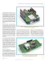
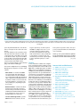
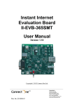
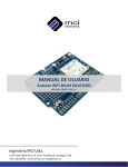
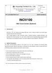
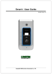
945772
MicroCONTROLLErs
Thou Shalt Communicate!
Wi-Fi/Bluetooth/USB shield
for Platino and Arduino
By Clemens Valens
(Elektor UK/INT Editorial)
can
also be used
stand-alone as a wireless connectivity module for
a PC. Note that you can’t have both
Wi-Fi and Bluetooth modules mounted on
the same board.
Today all &
sundry, devices
included, have to
be “connected”, 24/7, all
year round. You may have
a Facebook account, but
what about your oscilloscope?
Does your multimeter tweet
enough? Is your soldering iron
linked in? You may be a noncommunicative nerd but your
bench power supply may be
craving for social interaction.
With the add-on board described
in this article you can hook up
anything to everything, with or
without wires.
Okay, I can’t deny it; I
have a reputation for exaggerating. Connecting anything to, errm,
everything is probably a bit over the top. On
the other hand, the board I’m about to present in this article is quite versatile. It can
be equipped with a Wi-Fi module allowing
you to connect an electronic device to the
Internet; or with a serial Bluetooth module
it offers wireless connectivity to other serial
Bluetooth capable devices, and a serial-toUSB bridge enables old-skool wired serial
connectivity.
The board can be used as an add-on board
for microcontroller systems with Arduinostyle extension connectors (Figure 1), like
Elektor’s own Platino [1] (Figure 2), but it
About the Wi-Fi module
Wi-Fi modules have been inexpensive, plentiful and easy to find these past few years.
The problem with many of them however
is their manufacturer who refuses to tell
you how to use the module unless you
agree to transfer a substantial amount of
money to the manufacturer’s bank account
in exchange for a few thousand modules
or a customised software library for your
host hardware. Luckily the Korean embedded Internet liberators from WIZnet have
decided to be less secretive about their
products, and sell Wi-Fi modules you can
actually use. I managed to get my hands
on two of their WizFi220 modules, and this
article is the result.
28
10-2012
Personal Download for Lee, Jinyoung | copyright Elektor
elektor
945772
Wi-Fi/Bluetooth/USB shield for Platino and Arduino
The WizFi2x0 modules (there is also a
WizFi210 module) operates with standard
802.11 b/g/n access points at speeds up
to 11 Mbit/s (802.11b), and they support
WEP, WPA, WPA2-PSK and Enterprise security standards (802.11i). The modules have
some really cool possibilities. One of them
is the Wi-Fi serial port that’s remarkably
easy to use. Another nice feature is its limited access point (AP) capability that allows
direct connection to smartphones and tablets like Android-based devices and Apple
gadgets.
The WizFi220 module measures
32 x 23.5 x 3 mm, has an on-board chip
antenna and a Hirose U.FL connector for an
external antenna. The module’s compatible
little brother, the WizFi210, consumes less
power, but cannot provide as much output power and hence has “less range”. 49
connection pads provide enough soldering
points to fix the module on a PCB in such a
way that it will not easily come off. Most of
these pads are probably not useful for unassuming users like us, being pitched at highvolume customers. For the others a simple
two-wire serial connection is available to
transmit and receive data and to configure
the module.
Figure 1. Fully built up Wi-Fi shield on top of an Arduino Uno.
Note the absence of R8 and R10.
and a serial terminal program. That’s why
I decided to throw in a serial-to-USB converter. Since many Elektor readers may
already have a so-called FTDI serial USB
cable [2], I wanted to be able to use it
with this module. On the other hand, having such a converter directly on the board
would also be useful, especially if the host
system does not have a USB serial port,
like Platino. In the September 2011 edition
we presented BOB [3], a very convenient
USB/serial bridge module, and I thought
it was a good idea to add it to my design
too. Now if I could add some clever wiring
it should be possible to connect the USB
converter to either the Wi-Fi module, the
As is often the case with such wireless modules, the WizFi2x0 can be controlled over a
serial link using AT modem commands (or
Hayes commands). Such commands consist of human-readable strings a few characters long and starting with ‘AT’. The module
powers on in Command mode so you can
configure it. Once the setup is complete the
module can be switched into Data mode
with the O(nline) command (“ATO”). To
get it out of Data mode back to Command
mode three consecutive ‘+’ characters have
to be send (“+++”).
Design considerations
Some of the configuration commands, like
setting the baud rate of its serial port, are
more or less one-time only, and the module remembers these settings. Since the
AT commands are human-readable it may
therefore be practical for the initial setup,
but also for experimenting, to be able to
communicate with the module using a PC
elektor
Figure 2. Fully built-up Wi-Fi shield on top of Platino,
also equipped with a 20x4 alphanumerical LCD.
10-2012
29
Personal Download for Lee, Jinyoung | copyright Elektor
945772
MicroCONTROLLErs
AD
A5 A4 A3 A2 A1 A0
+3V3
IC1
MCP1825S-3302E/AB
K1
6
R11
C3
C4
10u
10V
100n
100n
10u
10V
* D1
* D3
* D2
4
3
2
1
8
7
6
5
2
R8
RXD
R10
25
1
46
8
10
11
12
13
14
15
16
17
19
20
ALARM1
UART0_RTS/GPIO25
UART1_RTS/GPIO27
UART0_TX/GPIO1
GPIO21/CLK_11MHZ
UART1_TX/GPIO2
GPIO29
UART1_RX/GPIO3
UART1_CTS/GPIO26
RTC_OUT1
DC_DC_CNTL
ALARM2
EXT_RESET
SSPI_MOSI
WizFi220
ADC1
SSPI_CS
ADC2
SSPI_CLK
MSPI_MISO/GPIO6
SSPI_MISO
MSPI_MOSI/GPIO7
I2C_DATA/GPIO8
MSPI_CLKI/GPIO5
GPIO20/CLK_22MHZ
VOUT_1V8
GPIO19/CLK_44MHZ
MSPI_CS0/GPIO4
PWM0/GPIO10
MSPI_CS1/GPIO13
I2C_CLK/GPIO9
GND
18
GND
31
36
42
35
41
TX_RADIO
27
40
RX_RADIO
26
39
38
23
+3V3
36
35
30
29
R2
T2
26
T1
24
2x
BC547B
23
22
SPI_MOSI
PIO6
SPI_CSB
PIO7
SPI_CLK
PIO8
SPI_MISO
PIO9
PCM_SYNC
PIO10
PCM_CLK
PIO11
RESET
UART_TX
UART_RTS
UART_RX
UART_CTS
1
R3
1k
2
3
JP3
6
5
4
3
2
1
18
32
33
34
22
25
16
28
30
24
C5
38
220n
29
+5V
+5V
+3V3
1
TX_MCU
RX_MCU
1
2
1
CBUS2
4
5
6
3
4
MOD3
RXD
CBUS0
CTS
RESET
RI
DCD
RTS
DSR
6
7
8
1
DTR
GND
ICSP
5
2
CBUS1
BOB-FT232R
*2
3
JP2
2
K5
CBUS3
TXD
RX_FTDI
3
CBUS4
+3V3
T3
2x
BC547B
19
VCIO
RX_MCU
R6
1k
31
TX_MCU
R5
T4
21
GND
TX_FTDI
48
20
PCM_OUT
GND
10
JP1
+3V3
R4
4
GND GND GND GND
21
GND
3
BTM-222
R1
28
27
PIO5
PCM_IN
1
1k
1
GND
43
USB_DN
GND
2
UART0_RX/GPIO0
15
PIO4
CTS
37
JTAG_NTRST
44
USB_DP
VCC
3
UART0_CTS/GPIO24
14
PIO3
TXO
7
GPIO31
45
AIO1
RXI
4
JTAG_TDI
13
37
AIO0
PIO2
DTR
6
GPIO30
JTAG_TMS
11
ASSOCIATED
RF_IO
MOD2
PIO1
9
RX
VCC
PIO0
6
1k
5
JTAG_TDO
+3V3
17
PVCC
5
8
47
*1
ANT_BT
OK
1k
4
GPIO28
JP5
+3V3
1k
47k
47k
R13 3
JTAG_TCK
1
2
12
MOD1
2
S1
34
EXT ANT
2
JP4
33
VBAT VIN_3V3 VIN_1V8 VDDIO
+3V3
R12
32
3
+5V
R9
7
9
4
LINK
1k
+3V3
5
1k
C2
1k
1k
C1
5V 3V3 RST IOREF
K2
+3V3
R7
POWER
GND
1k
+5V
VIN
3
4
5
6
7
8
9
10
2
#3
4
IOL
#5 #6
7
8
#9 #10 #11 12 13
IOH
SCL
1
SDA
K4
0
GND
120306 - 11
AREF
K3
Figure 3. Complete circuit diagram of the Wi-Fi/Bluetooth/USB shield.
Refer to the text to find out which parts you need for each configuration.
host system or even disconnect it. Flexibility started creeping into the design.
The Wi-Fi module has to be powered from a
3.3 V rail and it is not 5 V tolerant. The main
objective is to connect the Wi-Fi module’s
serial port to a microcontroller. Such a system may run from 3.3 V, but if it is Arduino
or Platino, then the microcontroller runs
from 5 V. Level converters on the serial port
would therefore be necessary. The FTDI
serial USB cable comes in two flavours, 5 V
and 3.3 V, and with level converters both
types would be usable. The BOB was not an
issue because it can handle both levels.
Although the host system may have a 3.3 V
rail, like Arduino, I thought it wise to add
a voltage regulator to the system because
the WizFi220 can consume up to 250 mA in
active mode. As an example, the LP2985-33
voltage regulator on an Arduino Uno board
is specified for 150 mA, which is clearly not
enough. Platino does not have a 3.3 V rail
so this shield could provide it too. A jumper
should allow connection of the 3.3 V as produced by the shield to the host system.
In this section you can replace all instances
of “Wi-Fi” by “Bluetooth” without having to
change anything else and still have a coherent text. Indeed, many Bluetooth modules
are very similar to the WizFi module: they
can be controlled with AT commands over
a serial link; they run from 3.3 V; they have
similar dimensions and similar requirements. It is therefore not very difficult to
add Bluetooth capabilities to the system,
all you have to do is wire a usable Bluetooth
module in parallel with the Wi-Fi module
and that is what I did. I chose the Rayson
BTM220 module because I am at ease with
it [4] and it is very cheap. We have used it
several times in Elektor too. [5][6]
This completes the reasoning that determined my design. Let’s now have a closer
look at the circuit diagram (Figure 3). If you
30
10-2012
Personal Download for Lee, Jinyoung | copyright Elektor
elektor
945772
Wi-Fi/Bluetooth/USB shield for Platino and Arduino
COMPONENT LIST
K2 = 6-pin stackable header, 0.1” pitch,
vertical
K5 = 6-pin (2x3) stackable header, 0.1”
pitch, vertical
S1 = pushbutton, SPNO, through-hole,
6x6mm
Mod3 = BOB-FT232R USB-to-Serial
Bridge, Elektor Shop # 110553-91, or
USB-to-Serial cable, Elektor Shop #
080213-71 (5 V) or # 080213-71 (3.3 V)
Mod2 = Rayson BTM22x Bluetooth
module
Mod1 = WIZnet WizFi2x0 Wi-Fi module
PCB # 120306-1 [1]
Resistors
R1–R11 = 1kΩ 5% 0.25W
R12,R13 = 47kΩ 5% 0.25W
Capacitors
C2, C3 = 100nF 50V, 5mm pitch
C5 = 220nF 50V, 5mm pitch
C1, C4 = 10µF 35V, 2.5mm pitch
Semiconductors
D1,D2,D3 = LED, green, 3mm diam.
T1–T4 = BC547C, TO-92 case
IC1 = MCP1825S-3302E/AB, 3.3 V voltage regulator, TO-220 case
Miscellaneous
JP1 = 6-pin pinheader, 0.1” pitch,
straight
JP3,JP4 = 3-pin pinheader, 0.1” pitch, straight,
w. 2 jumpers
have grasped my prose up to here, then the
schematic will have only a few surprises.
Putting it all together
On the left side of figure 3 we have the Wi-Fi
module; on the right side we see the Bluetooth module. As you can see they share
the serial RX and TX lines, meaning that
you should not mount both. It is either
Wi-Fi or Bluetooth, never both. The modules also share two LEDs (D1 and D2); D3
is only used by the Wi-Fi module. A surprise
here may be R8 and R10. Maybe I could have
drawn a better schematic, but I didn’t, so
I have to explain this in writing. It is actually very simple. The Wi-Fi module sinks the
current for the LEDs whereas the Bluetooth
sources the current. As a result the LEDs
have to be mounted the other way around
as drawn if you use the Bluetooth module.
In that case you should mount R8 and R10
and not mount R7 and R9 (mounting R11
and D3 is useless unless you connect the
LED to a free I/O pin on one of the connec-
JP2 = 4-pin pinheader, 0.1” pitch, straight
K1,K3, K4 = 8-pin stackable header, 0.1” pitch,
vertical
tors). For the Wi-Fi module the position of
the LEDs is drawn correctly and you should
not mount R8 and R10 (although nothing
breaks or blows if you do), only R7 and R9
are needed now.
The WizFi module has some pins with special functions that you may want to use.
Since I didn’t use them I wired them to a
separate connector JP4. To enable you all
to stack many shields on top of each other
I decided not to wire these signals to the
Arduino extension connectors K1 to K4. If
you need them you can wire them yourself. Pin 25 (GPIO 21) allows you to restore
the module’s factory defaults. Pulsing it
Low twice will restore the module to Limited Access Point mode, three pulses will
restore it to Ad-hoc mode. Pin 46 (GPIO 29)
provides a hardware way of switching
between Command (High) and Data
mode (Low). Pin 37 (GPIO 27) is needed
when you want to upgrade the firmware
of the module (probably never). To do so
you have to pull it High. Finally, a low level
on pin 7 (Alarm1) will wake up the module
from deep sleep mode.
The level converters (R1-3, T1-2 and R4-6,
T3-4) are straightforward and have been
used before in Elektor. Transistors T1 and T4
do the level conversion, but invert the signal at the same time. T2 and T3 correct this.
The resistor values are not critical. I chose to
use as many 1 kΩ resistors as possible.
The RX and TX lines connect to JP1 and JP2.
These 3-pin jumpers may be a bit difficult
to understand at first sight, but when you
follow the lines you should be able to figure them out. With a jumper on JP1’s pins
1 and 2 the USB serial converter TX pin
is connected to the Wi-Fi (or Bluetooth)
module’s RX input. A jumper on JP2’s pins
2 and 3 connects the USB serial converter
RX pin to the Wi-Fi (or Bluetooth) module’s
TX output. This is the Configure-ModuleWith-PC mode. In these positions the USB
serial converter cannot talk to the host MCU
system and it may be better to disconnect
Elektor Projects & Products
•Platino, a versatile board for AVR microcontroller circuits (October 2011); PCB # 100892-1 from Elektor Shop
•BOB-FT232R USB-to-Serial Bridge (September 2011); module, Elektor Shop # 110553-91
•USB-to-TTL Serial Cable (June 2008); cable, Elektor Shop # 080213-71 (5 V) or # 080213-71 (3.3 V)
elektor
10-2012
31
Personal Download for Lee, Jinyoung | copyright Elektor
945772
MicroCONTROLLErs
Listing 1.
Example of setting up the WizFi2x0 module as a serial server using AT commands. The commands are in boldface, the module’s responses
are in italic. Comments appear in brackets (). See the WizFi2x0 user manual for more commands.
AT (wake up)
[OK]
AT+NSTAT=? (what is your status?)
MAC=00:08:dc:18:97:76
WSTATE=NOT CONNECTED
MODE=NONE
BSSID=00:00:00:00:00:00
SSID=”” CHANNEL=NONE
SECURITY=NONE RSSI=0
IP addr=0.0.0.0
SubNet=0.0.0.0 Gateway=0.0.0.0 DNS1=0.0.0.0 DNS2=0.0.0.0
RxCount=0 TxCount=0
[OK]
AT+WPAPSK=germaine,”Philippe Noirette” (set SSID & pass phrase)
Computing PSK from SSID and PassPhrase...
[OK]
AT+NDHCP=1 (request IP number from DHCP server)
[OK]
AT+WAUTO=0,germaine (automatically connect to germaine)
[OK]
AT+NAUTO=1,1,,8011 (setup for auto connect: server, TCP, port 8011)
[OK]
ATA (start auto connect)
IP
SubNet
Gateway
192.168.2.7: 255.255.255.0: 192.168.2.1
[OK]
(now you can connect (telnet) to the module over Wi-Fi)
the board from the host system. The board
will be powered from the USB port.
If you put a jumper on JP1’s pins 2 and 3
and on JP2’s pins 1 and 2 the USB serial converter can be used to talk to the host system. In this case you should not mount the
wireless module (or the level converters) as
this kind of communication may disturb it.
This is the USB-Shield mode.
Not installing any jumpers will put the
board in Wireless mode and the USB serial
converter has no use. However, you could
leave it on and wire it to other pins on the
extension connectors. This is for instance
useful in an Arduino-with-software-UART
configuration or in a host system with more
than one UART.
Finally some remarks on details. The Reset
button is mainly intended for Platino which
doesn’t have one. It is also useful when the
Arduino reset button becomes inaccessible
because of the shield mounted on top of
it. This depends on the Arduino board and
its revision.
K5 is not connected. I only put it on the
board to provide access to its signals if the
host is Arduino.
Turning practical
To turn a circuit diagram into a real shield
or extension board a printed circuit board
(PCB) is needed. I designed one and you can
download the Eagle CAD files from the web
page that accompanies this article [7]. The
PCB is the size of an Arduino Uno except that
it is a rectangle without the funny-shaped
short side of an Arduino Uno. All the components are through-hole types; only the Wi-Fi
and Bluetooth modules have surface mount
footprints. JP5 and the Bluetooth module are
located on the solder side of the board; the
other components should go on the component side. Note that if you use non-stackable
connectors for K1 to K4 you should mount
them on the solder side if you want to stick
the board on an Arduino or Platino.
JP1 and JP2 are positioned in such a way that
the jumpers should always be in the same
position, i.e. both to the left, both to the
right or both absent. Actually, you could
leave a jumper on JP2 in case you wanted to
listen in on the MCU wireless module communications. This can be useful for debugging purposes.
JP3 has a few contacts in common with the
BOB serial-to-USB bridge, the idea being
that you use either a BOB or an FTDI cable,
not both.
For full 3.3 V systems the level converters
and voltage regulator can be left off. In this
case you have to place two bypasses (wire
bridges) from R3-JP1 to R2-T2 and from
R6-MOD1 to R5-T3. Resistors R3 & R2 and
R5 & R6 are positioned in such a way that
the wire bridges are very easy to install and
32
10-2012
Personal Download for Lee, Jinyoung | copyright Elektor
elektor
945772
Wi-Fi/Bluetooth/USB shield for Platino and Arduino
Figure 4. The three main configurations next to each other. The Bluetooth module is not visible (middle board) because it is mounted on
the other side of the PCB. Note that this is an early revision of the PCB that has the same shape as an Arduino Uno board. The final PCB is
rectangular.
span only minimum distance. You will also
have to short JP5 on the solder side of the
board.
As mentioned before, the orientation of the
LEDs depends on the wireless module. The
component print on the PCB corresponds
to the Wi-Fi module. If you mount a Bluetooth module you should mount the LEDs
D1 and D2 ‘the wrong way around’. Also,
only mount R7 or R8 and R9 or R10.
The 3.3 V voltage regulator can be installed
lying on his back or standing up.
Three main configurations are possible (Figure 4), but you may have a need for other
variants:
•Wi-Fi shield — no need for the BOB if
you own an FTDI cable, although you
can always install one. JP3 is available
for connecting the FTDI cable. Mount all
LEDs as indicated on the PCB and do not
mount R8 nor R10. Level converters will
be needed and the 3.3 V voltage regulator probably too, depending on your
host system.
•Bluetooth shield — similar as the Wi-Fi
shield except for the LEDs. D3 has no
function and you should not mount R7
and R9 but mount R8 and R10 instead.
As an antenna you can use a piece of
(insulated) wire of 31 mm long.
•Serial-to-USB bridge shield — just the
BOB without level converters. Do not
elektor
forget to put a drop of solder on JP1 of
the BOB to configure it for 5 V or 3.3 V
operation. Add 3.3 V voltage regulator and reset push button to taste. The
LEDs can be useful too, but you will have
to wire them to a connector pin. You
should short pins 2 and 3 of JP1 and pins
1 and 2 of JP2 with a jumper or a wire
bridge.
host system responds to these. It is up to
you to provide a host that can communicate
over a serial link.
Thanks go out to Joachim Wulbeck of WIZnet
Europe GmbH (www.wiznet.eu) for providing
the WizFi220 modules and the Wi-Fi antennas.
(120306-I)
Testing
In case of the Wi-Fi or Bluetooth configurations connect the board to a USB port on the
PC using an FTDI serial converter cable or the
BOB serial-to-USB bridge. Figure out which
COM port was created by the operating system (OS) of your PC (make sure you have the
appropriate drivers for your OS installed. If
you haven’t you can get them, including the
necessary documentation, at www.ftdichip.com) and start a serial terminal program. The WizFi220 module has a default
baud rate of 115 200 bits/s, for the BTM220
module this value is 19 200. Both modules
use 8 bits, no parity and no hardware flow
control. In the terminal type ‘AT’ followed
by the Enter key. If you set up everything the
right way the module should respond with
‘[OK]’ or ‘OK’. If this test succeeds you’re
in business. Refer to Listing 1 for a working
Wi-Fi example (don’t forget to adapt the
SSID and pass phrase to your network).
For a BOB serial-to-USB bridge configuration the steps are more or less the same
except that there is no point in punching in
AT commands in the terminal unless your
Internet Links and References
[1] Platino: www.elektor.com/100892
[2] USB-to-TTL serial cable:
www.elektor.com/080213
[3] BOB serial-to-USB bridge:
www.elektor.com/110553
[4] Experiments with Rayson Bluetooth
modules:
http://elektorembedded.blogspot.
com/2010/08/rayson-btm222-btm112bluetooth-modules.html
[5] Bluetooth with the ATM18:
www.elektor.com/080948
[6] Bluetooth for OBD-2:
www.elektor.com/090918
[7] Wi-Fi shield: www.elektor.com/120306
[8] Wi-Fi shield on Elektor Projects:
http://www.elektor-projects.com/project/wi-fi-bluetooth-usb-shield-for-arduino-platino.12252.html
10-2012
33
Personal Download for Lee, Jinyoung | copyright Elektor