1
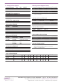
WiFi1500CF Terminus Plug-In
Product User Manual
Bulletin
Revision
Date
JA03-UM-WiFi
P00
13 March 2014
TABLE OF CONTENTS
TABLE OF CONTENTS and DISCLAIMER.............................................................................................................................. 2
1 Scope .............................................................................................................................................................................. 3
2 WiFi1500CF Overview....................................................................................................................................................... 3-6
2.1 Absolute Maximum Ratings...................................................................................................................................... 3
2.2 Recommended Operating Conditions...................................................................................................................... 3
2.3 Plug-In Pin-Out......................................................................................................................................................... 4
2.4 Power Connections................................................................................................................................................... 5
2.5 Screw Mount............................................................................................................................................................. 6
3 Wi-Fi Module................................................................................................................................................................... 7-10
3.1 Wi-Fi Module Connections....................................................................................................................................... 7
3.2 Wi-Fi Module Operations....................................................................................................................................... 8-9
3.3 Wi-Fi Module Firmware.......................................................................................................................................... 10
4 GPS Module (Optional)................................................................................................................................................. 11-12
4.1 GPS Module Connections...................................................................................................................................... 11
4.2 GPS Module Operation.......................................................................................................................................... 12
5 Configuration Options................................................................................................................................................... 13-14
6 Specifications..................................................................................................................................................................... 15
7 Ordering Information.......................................................................................................................................................... 16
8 Applicable Documents...................................................................................................................................................... 16
9 Revision History................................................................................................................................................................. 16
DISCLAIMER
The information contained in this document is the proprietary information of Connor-Winfield Corporation and its affiliates (Janus Remote Communication). The contents are confidential and any disclosure to
persons other than the officers, employees, agents or subcontractors of the owner or licensee of this document, without the prior written consent of Connor-Winfield, is strictly prohibited. Connor-Winfield
makes every effort to ensure the quality of the information it makes available. Notwithstanding the foregoing, Connor-Winfield does not make any warranty as to the information contained herein, and does
not accept any liability for any injury, loss or damage of any kind incurred by use of or reliance upon the information. Connor-Winfield disclaims any and all responsibility for the application of the devices
characterized in this document, and notes that the application of the device must comply with the safety standards of the applicable country, and where applicable, with the relevant wiring rules. ConnorWinfield reserves the right to make modifications, additions and deletions to this document due to typographical errors, inaccurate information, or improvements to programs and/or equipment at any time
and without notice. Such changes will, nevertheless be incorporated into new editions of this application note.
All rights reserved 2014 Connor-Winfield Corporation
WiFi1500CF Plug-In Hardware User Guide JA03-UM-WiFi
Page 2
Rev: P00
Date: 03/13/14
© Copyright 2014 Janus Remote Communications Specifications subject to change without notice
All Rights Reserved See website for latest revision.
Not intended for life support applications.
1. Scope:
This document provides a detailed hardware interface description and some general operating instructions for the
WiFi1500CF. It does not cover the detailed operating instructions of the individual WiFi (GS1500M) or GPS (JN3)
modules. Please refer to the documentation listed in the Applicable Documents section for further information
concerning operation of these modules.
2. WiFi1500CF Overview
The WiFi1500CF provides Wi-Fi connectivity and an optional GPS receiver in a footprint compatible with the Janus
line of Terminus Plug-In products. A GainSpan GS1500M module provides WiFi 802.11 b/g/n radio features and
comes with S2W (Serial-to-Wi-Fi) application firmware. The GS1500M is easily configured via an AT type command
set over a UART interface, and support for a SPI interface is available through an optional firmware load. A Telit JN3
GPS receiver is available as an option and provides a standard NMEA UART interface and 1PPS output for tracking
solutions and precision timing requirements.
The power supply and I/O signals are compatible with Janus Terminus Plug-In host products such as the T2 and
400AP, or the WiFi1500CF can be used in a custom based solution. The WiFi1500 was specifically designed
to provide customers with a cost effective product that is easily integrated into new and existing designs. It is
completely interchangeable with other Terminus Plug-In products to allow for maximum network flexibility while
removing the worry of product obsolescence.
2.1 Absolute Maximum Ratings:
Parameter
Min
Operating Temperature
-40
Storage Temperature
-40
SUPPLY (input)
GPS antenna bias (output)
Typ
Max
Unit
-
-
-
-
+85
+85
6.0
TBD
°C
°C
volts
mA
Typ
Max
Unit
Note
2.2 Recommended Operating Conditions:
Parameter
Min
Operating Temperature
-40
-
+85
Storage Temperature
-40
-
+85
SUPPLY (input)
4.75
.0
5.25
SUPPLY (input) [w/ GPS]
TBD
SUPPLY (input) [w/o GPS]
TBD
PWRMON/VAUX (output; @ 2.8V)
100
TBD
PWRMON/VAUX (output; @ 3.3V)
200
TBD
GPS antenna bias (output)
3.3
Note
°C
°C
volts
mA WiFi1500CF v1.0
mA WiFi1500CF v2.0
mAdefault configuration
mAoptional configuration
volts
WiFi1500CF Plug-In Hardware User Guide JA03-UM-WiFi
Page 3
Rev: P00
Date: 03/13/14
© Copyright 2014 Janus Remote Communications Specifications subject to change without notice
All Rights Reserved See website for latest revision.
Not intended for life support applications.
2. WiFi1500CF Overview continued
WiFi1500CF
VIO
VAUX
VIO POWER
GS1500M
WiFi MODULE
LEVEL
TRANSLATORS
UART0
UART I/O
SPI
SPI I/O
RF
WiFi ANTENNA
CONNECTOR
RF
GPS ANTENNA
CONNECTOR
GPIO
GPIO10,31
UART1
ANALOG I/O
I2C
SERVICE
PROGRAM
RESET
RESET
VIO POWER
GPIO30
JN3
GPS MODULE
LEVEL
TRANSLATORS
UART I/O
UART
1PPS
1PPS
SUPPLY
WiFi POWER
ENABLE
VIO POWER
GPS POWER
DISABLE
Components not populated on WiFi1500CF v2.0 (without GPS)
Figure 1. WiFi1500CF Block Diagram
Figure 1 WiFi1500CF Block Diagram
WiFi1500CF Plug-In Hardware User Guide JA03-UM-WiFi
Page 4
Rev: P00
Date: 03/13/14
© Copyright 2014 Janus Remote Communications Specifications subject to change without notice
All Rights Reserved See website for latest revision.
Not intended for life support applications.
2. WiFi1500CF Overview continued
2.3 Plug-In Pin-Out
Pin
1
2
3
4
5
6
7
8
9
10
11
12
13
14
15
16
17
18
19
20
21
22
23
24
25
26
27
28
29
30
31
32
33
34
35
36
37
38
39
40
41
42
43
44
45
46
47
48
49
Name
SUPPLY
SUPPLY
DISABLE WiFi
RXD
N/C
CTS
N/C
1PPS
TXD
N/C
RTS
GROUND
UART1_TX
UART1_RX
GPIO30
GPIO31
SERVICE
PWRMON
N/C
RESET
N/C
N/C
N/C
N/C
GROUND
GROUND
N/C
N/C
N/C
N/C
I2C_SDA
I2C_SCL
GPS_RX
GPS_TX
N/C
ASYNC
GPIO10
SPI_WAKE
GROUND
SPI_MISO
SPI_MOSI
SPI_CS
SPI_CLK
ADC1
ADC2
ADC1
N/C
VAUX
GROUND
Description
5.0 +/- 0.5 V Positive Supply Input
5.0 +/- 0.5 V Positive Supply Input
Disable WiFi Supply
GS1500M UART0_TX
No Connection
GS1500M UART_RTS
No Connection
GPS 1PPS output
GS1500M UART0_RX No Connection
GS1500M UART0_CTS
Supply Reference
GS1500M UART1_RX
GS1500M UART1_TX
GS1500M GPIO30
GS1500M GPIO31
Enable Firmware Load
Reference Voltage
No Connection
Reset Cellular Radio
No Connection
No Connection
No Connection
No Connection
Supply Reference
Supply Reference
No Connection
No Connection
No Connection
No Connection
GS1500M 12C Data
GS1500M 12C Clock
GPS UART - RX GPS UART – TX No Connection
GS1500M GPIO19-ASYNC
GS1500M GPIO10
GS1500M SPI_WAKE
Supply Reference
GS1500M SPI_DOUT
GS1500M SPI_DIN
GS1500M SPI_CS
GS1500M SPI_CLK
GS1500M A/D Converter 1
GS1500M A/D Converter 2
GS1500M A/D Converter 1
No Connection
Reference Voltage
Supply Reference
NOTES:
N/A – not applicable
VIO – I/O logic level. VIO is 2.8V by default; can be configured to 3.3V by
changing 0 ohm jumpers on the board.
1. SUPPLY pins are internally connected.
2. Disable input for WiFi supply (independent of GPS supply). Pin is
internally pulled up to SUPPLY voltage and can be left floating for alwayson operation. For shutdown, pull low with open collector/drain driver.
3. The GS1500M UART interfaces are cross connected to appear as a
DCE devices on the WiFi1500CF pinout.
4. N/C (no connection). The pin has no function and makes no electrical
connection.
I/O Signal
Power Input
Power Input
CMOS Input
CMOS Output
N/A
CMOS Output
N/A
CMOS Output
CMOS Input
N/A
CMOS Input
Power
CMOS Input
CMOS Output
CMOS Bi-Direction
CMOS Bi-Direction
TTL Input
Analog Output
N/A
CMOS Input
N/A
N/A
N/A
N/A
Power
Power
N/A
N/A
N/A
N/A
CMOS Bi-Direction
CMOS Bi-Direction
CMOS Input
CMOS Output
N/A
CMOS Output
CMOS Bi-Direction
CMOS Output
Power
CMOS Output
CMOS Input
CMOS Input
CMOS Input
Analog Output
Analog Input
Analog Input
N/A
Analog Output
Power
I/O Level
N/A
N/A
SUPPLY
VIO
N/A
VIO
N/A
VIO
VIO
N/A
VIO
N/A
VIO
VIO
VIO
VIO
VIO
N/A
N/A
N/A
N/A
N/A
N/A
N/A
N/A
N/A
N/A
N/A
N/A
N/A
N/A
N/A
VIO
VIO
N/A
VIO
VIO
VIO
N/A
VIO
VIO
VIO
VIO
N/A
N/A
N/A
N/A
N/A
N/A
Pull Type
N/A
N/A
PULL-UP to SUPPLY
N/A
N/A
N/A
N/A
N/A
N/A
N/A
N/A
N/A
N/A
N/A
N/A
N/A
PULL-UP to VIO
N/A
N/A
PULL-UP to 3.3V N/A
N/A
N/A
N/A
N/A
N/A
N/A
N/A
N/A
N/A
N/A
N/A
N/A
N/A
N/A
N/A
N/A
N/A
N/A
N/A
N/A
N/A
N/A
N/A
N/A
N/A
N/A
N/A
N/A
Notes
1
1
2
3
4
3
4
5,9
3
4
3
6,9
6,9
9
7
4
8
4
4
4
4
4
4
4
4
5,6
5,6
9
9
4
5,6
5,6
5,6
4
-
5. Must be enabled by installing 0 ohm jumpers on the board. See
Configuration Options section.
6. Not supported in standard firmware
7. Enable input for loading GS1500 firmware. Pin is internally pulled up
to VIO voltage and can be left floating. For enabling firmware load,
pull low with open collector/drain driver. (There is also provision for a
jumper for this on the board.).
8. Connected to GS1500 RESET pin and a 22K pullup resistor to 3.3 V
through a 1 k series resistor.
9. Only available on WiFi1500CF V1.0 boards (with GPS). Pin is N/C
(no connection) on WIFi1500CF V2.0 boards.
WiFi1500CF Plug-In Hardware User Guide JA03-UM-WiFi
Page 5
Rev: P00
Date: 03/13/14
© Copyright 2014 Janus Remote Communications Specifications subject to change without notice
All Rights Reserved See website for latest revision.
Not intended for life support applications.
2. WiFi1500CF Overview continued
2.4 Power Connections
SUPPLY – 5.0 volt supply for the module (referenced to the GROUND pins). The two SUPPLY pins (pins 1 and 2) are
internally connected together.
PWRMON / VAUX – These pins are connected to the internal VIO supply that powers the level shifters used on
several of the I/O pins. The two pins are internally connected; the different names are used to maintain compatibility
with other Terminus Plug-In products. This voltage can be used as a reference for an external interface. The VIO
supply can be connected to an internal 2.8 volt supply or an internal 3.3 volt supply. The default is the 2.8 volt
supply so as to be compatible with the Terminus Plug-In host products (e.g T2, 400AP). See the Configuration
Options section for information on changing the VIO supply.
The following I/O pins use the level shifters or are associated with the VIO supplies:
Pin
Name
4
6
8
9
11
13
14
15
16
17 RXD
34GPS_RX1
CTS
35GPS_TX1
1
1PPS 36ASYNC
TXD
37GPIO10
RTS
38SPI_WAKE
UART1_TX
40SPI_MISO
UART1_RX
41SPI_MOSI
GPIO301
42SPI_CS
GPIO31
43SPI_CLK
SERVICE2
PinName
1. These pins are not connected on the WiFi1500CF v2.0 (w/o GPS)
2. This pin uses a discrete transistor implementation for a level shifter.
ENABLE – Used to disable the GS1500M and level shifter power supplies. This pin is internally pulled up to the
SUPPLY voltage which enables the power supplies by default. Pulling this pin low will disable the internal GS1500M
and level shifter power supplies. The GPS supply is unaffected. This can allow for reduced power consumption by
disabling the GS1500M WiFi module while allowing the GPS receiver to continue to operate.
2.5 Screw Mounting
The WiFi1500CF allows for the use of a #4 machine screw to help keep a socketed module in place where
environmental variables may cause problems otherwise. If the user wishes to have a stand-off underneath the
module to help alleviate possible stress from mounting hardware, below are the Janus part numbers and associated
drawings for an available solution.
4-40 Hex Female Stand-off: MC-0356-G
4-40 3/16” Pan Head Phillips Machine Screw: MC-0357-G
Figure 2. Screw Diagram
WiFi1500CF Plug-In Hardware User Guide JA03-UM-WiFi
Page 6
Rev: P00
Date: 03/13/14
© Copyright 2014 Janus Remote Communications Specifications subject to change without notice
All Rights Reserved See website for latest revision.
Not intended for life support applications.
3. WiFi Module
The GainSpan GS1500M provides the WiFI connectivity for the WiFi1500CF. A complete description of this module
is beyond the scope of this document. Detailed hardware and operational information can be found in the GS1500M
documentation listed in the Applicable Documents section.
3.1 WiFi Module Connections
The connections between the GS1500M module and the WiFi1500CF pins are shown in the table below.
GS1500M
Pin Name
Interface
WiFi1500CF
Pin
Name
1
GND
GND
2
JTAG_TCLK
N/C
3
JTAG_TDO
N/C
4
JTAG_TDI
N/C
5
JTAG_TMS
N/C
6
JTAG_nTRST
N/C
7
ALARM1
N/C
8
RTC_OUT1
N/C
9
VBAT
3.3V
10
DC_DC_CNTL
N/C
11
ADC1
---
44,461 ADC1
12
ADC2
---
451
ADC2
13
ALARM2
N/C
14
MSPI_DIN
N/C
15
MSPI_DOUT
N/C
16
VOUT_1V8
Internal2
17
GND
GND
18
MSPI_CLK
N/C
19
MSPI_CS0
N/C
20
MSPI_CS1
N/C
21
GPIO21
N/C
22
GPIO20
N/C
23
GPIO19
Level Shifter
36
ASYNC
24
GPIO10
Level Shifter
37
GPIO10
GS1500M
Pin Name
Interface
25
26
27
28
29
30
31
32
33
34
35
36
37
38
39
40
41
42
43
44
45
46
47
48
--
I2C_CLK
I2C_DATA
SSPI_DOUT
SSPI_CLK
SSPI_CS
SSPI_DIN
VIN_3V3
GND
EN_1V8
VDDIO
UART1_CTS
UART1_RTS
UART1_RX
UART1_TX
UART0_TX
UART0_RTS
UART0_RX
UART0_CTS
GPIO31
GPIO30
GPIO29
GPIO28
EXT_RSTn
GND
Antenna
WiFi1500CF
Pin Name
Pullup to VIO
321
Pullup to VIO
311
Level Shifter
44
Level Shifter
43
Level Shifter
42
Level Shifter
41
3.3V
GND
3.3V
3.3V
N/C
Pullup to VIO
17
Level Shifter
13
Level Shifter
14
Level Shifter
4
Level Shifter
6
Level Shifter
9
Level Shifter
11
Level Shifter
16
Level Shifter
15
N/C
Level Shifter
38
Pullup to 3.3V 20
GND
u.FL connector
I2C_SCL
I2C_SDA
SPI_MISO
SPI_CLK
SPI_CS
SPI_MOSI
SERVICE
UART1_TX
UART1_RX
RXD
CTS
TXD
RTS
GPIO31
GPIO30
SPI_WAKE
RESET
1 Jumpers must be installed to connect these pins. See the Configuration Option section.
2 The GS1500M VOUT_1V8 pin can be jumpered to the JN3 module’s BOOT pin. See the Configuration Option section.
Antenna
The GS1500M has an on-board PCB (printed circuit board) antenna and a u.FL RF connector to support an external WiFi
antenna. The u.FL connector is located on the edge of the GS1500M module board that overhangs the WiFi1500CF board.
Commands entered via the GS1500’s UART or SPI port can be used to select which antenna is used.
UART interface
UART0 on the GS1500M is brought out through a level shifter and support is provided for TX, RX, CTS and RTS signals. While
the GS1500 has DTE (Data Terminal Equipment) UART configuration, an internal crossover network converts this to appear
as a DCE (Data Communications Equipment) device on the pin-out of the WiFi1500CF. This makes it compatible with host
processors (e.g. Janus 400AP, T2) and other microcontroller devices that typically present a DTE UART interface. The default
settings for the UART0 interface are 9600 baud, 8 bit characters with no parity bits and one stop bit (8N1).
ASYNC
Connected to the GS1500M GPIO19 pin through a level shifter. When enabled via the command interface, this pin can be
used to provide notification of asynchronous messages at the UART0 port. (See ‘Enhanced Asynchronous Notification’ in the
GS1500M Serial-to-WiFi Adapter Application Programming Guide.)
SPI interface
The GS1500M SPI slave port is brought out through a level shifter and support is provided for the SPI_MISO, SPI_MOSI, SPI_CS,
SPI_CLK and the SPI_WAKE pins. The SPI port provided as an alternative to the UART0 interface on the GS1500M, and can
provide faster communication speeds (up to 3 Mbps) than the UART0 interface.
SPI_WAKE
Connected to the GS1500M GPIO28 pin through a level shifter. This pin is asserted high during data transmission periods.
It notifies the host (SPI master) that it can begin receiving data by providing the SPI clock signal. In addition, it provides an
indication that the SPI interface is operational following start up. (See ‘SPI Interface Handling‘ and ‘Node Start Up Handling’ in
the GS1500M Serial-to-WiFi Adapter Application Programming Guide.)
WiFi1500CF Plug-In Hardware User Guide JA03-UM-WiFi
Page 7
Rev: P00
Date: 03/13/14
© Copyright 2014 Janus Remote Communications Specifications subject to change without notice
All Rights Reserved See website for latest revision.
Not intended for life support applications.
3. WiFi Module Continued
3.2 WiFi Module Operations
Operation of the GS1500M WiFi module requires a serial connection to the device, either through its UART0 port
or its slave SPI port. (The SPI Mode 0 firmware load is required to support the SPI port connection.) Operational
commands and data strings are transferred using the serial connection. A complete description is beyond the scope
of this User Manual; please refer to the GS1500M Serial-to-WiFi Adapter Application Programming Guide.
The GS1500M can operate in 3 different modes that are related to how the serial interface is utilized:
Command mode (default) – Command strings using an ‘AT’ command format can be used to configure the module.
Data processing mode – Using escape character sequences, data can be sent and received from up to 16
different IP address-port locations.
Auto connect mode – The module can be pre-configured to connect to a network at start-up as either a TCP
or UDP client or server. Following start-up, serial data is automatically sent to and received from a remote IP
address via the selected protocol.
3.2.1 Set-up:
This section describes the minimum hardware set-up requirements and some basic command procedures to
operate the GS1500M module.
3.2.1.1 Hardware Set-up
Hardware set-up requires the following:
-
UART connection (GS1500M UART0). At a minimum the TX and RX lines must be supported. The WiFi1500CF
interface pins are at VIO voltage levels; the default value is 2.8 volts. The default UART configuration is 9600 baud, 8
bits, no parity, 1 stop bit (8N1).
-
Antenna selection. The GS1500M has a printed circuit antenna that is selected by default. Alternatively, an external
WiFi antenna may be connected to the u.FL connector on the GS1500M module board. In this case the U.FL
connector antenna must be selected via a AT command; see the Basic Configuration section below.
-
Power. Apply power to the unit by providing 5.0 +/- 0.25 volts across the WiFi1500CF SUPPLY and GND pins.
3.2.1.2 Basic Commands:
In general, the AT commands are insensitive to character case. Successful commands usually return the characters “OK”
(if the default verbose mode is enabled). Please refer to the GS1500M Serial-to-WiFi Adapter Application Programming
Guide for details. Those commands requiring user parameters are indicated with the parameter being given in inequality
brackets, e.g. <PARAMETER>. Below are a few basic commands that can be used to demonstrate serial connectivity
with the GS1500M:
AT+NSTAT=?
AT+WS
WT+NMAC=?
Network Status query
Scan for WiFi networks
MAC address query
The following disassociate command should be used before proceeding with any of the operational examples given in the
sections below to insure that any previous operating mode is cleared:
AT+WD
Disassociate
AT&F
Restore to factory defaults
A reset to factory default conditions can be achieved with the following command:
3.2.1.3 Basic Configuration:
When first powered, the GS1500M module will initialize and then send “Serial2WiFi APP” to the UART port, whereupon
the module is ready to receive commands. (If the module has been configures to auto connect, a network status message
is sent instead.)
The antenna output should be set to the printed circuit board antenna or the external antenna connected to the u.FL
connector. The antenna selection command is:
AT+ANTENNA=<n>
Where <n> specifies whether the printed circuit board antenna or the external u.FL antenna is selected:
1 = printed circuit board antenna
2 = u.FL connector
WiFi1500CF Plug-In Hardware User Guide JA03-UM-WiFi
Page 8
Rev: P00
Date: 03/13/14
© Copyright 2014 Janus Remote Communications Specifications subject to change without notice
All Rights Reserved See website for latest revision.
Not intended for life support applications.
3. WiFi Module Continued
3.2 WiFi Module Operations continued
3.2.2 Operation examples
Below are several examples of configuring the GS1500M module. The UDP Client example configures the
module to connect to an existing infrastructure WiFi network using command mode, then sends UDP data to
a server using data mode. The Web Provisioning example is a command mode sequence of instructions that
initiates the module’s provisioning web server. The Auto Connect example configures the unit to automatically
connect as a TCP server to a specific client. Upon restart in the Auto Connect mode a connection is made
between the client and server, at which point data can be transparently passed back and forth between them.
These examples assume that the GS1500M WiFi module begins configured in its default state, and that no
encryption is used.
3.2.2.1 UDP Client
Issuing the following sequence of commands will set up the GS1500M module as a station in an existing infrastructure WiFi
network:
AT+WM=0
Mode (0=infrastructure).
AT+NDHCP=1
DHCP (1=enable).
AT+WA=<SSID>
Associate with a WiFi network having
designated SSID.
AT+NCUDP=<Dest-Address>,<Port>
Returns: CONNECT <CID>
Setup UDP Client. Successful Command will return
a Connection Identifier number.
At this point UDP data can be sent to a server (at <Dest-address>, <port>) with the following command:
<Esc>S<CID><data><Esc>E
Send UDP data.
3.2.2.2 Web Provisioning
The web provisioning feature included in the default firmware load allows the GS1500M to host a few simple web pages
that allow for provisioning of the module. It can be set by issuing the following commands:
AT+NSET=<IP>,<SUBNET MASK>,<GATEWAY IP> Static Configuration.
AT+WM=2
Mode (2=limited Access Point).
AT+WA=<SSID>,,<CHANNEL>
Start AP network using SSID on designated CHANNEL.
AT+DHCPSRVR=1
DHCP server (1=enable).
AT+WEBPROV=<USERNAME>,<PASSWORD>
Start web provisioning. The USERNAME and PASSWORD
will be required to login.
At this point a client can connect to the GS1500M module at it’s <IP> address. The GS1500M will request the
<USERNAME> and <PASSWORD> to be entered. This gives access to web pages hosted on the module that allow for
provisioning of the GS1500M.
WiFi1500CF Plug-In Hardware User Guide JA03-UM-WiFi
Page 9
Rev: P00
Date: 03/13/14
© Copyright 2014 Janus Remote Communications Specifications subject to change without notice
All Rights Reserved See website for latest revision.
Not intended for life support applications.
3. WiFi Module Continued
3.2 WiFi Module Operations continued
3.2.2 Operation examples
3.2.2.3 Auto Connect
In the example below, the GS1500M module is configured to connect to an access point, the auto connect feature is
enabled, and the settings are stored in a profile. When re-started, the unit will connect to the access point whereupon
serial data can be transferred to and from a remote IP address.
AT+NDHCP=1 DHCP enable
AT+WAUTO=0,<SSID> Set auto wireless parameters (0=infrastructure).
AT+NAUTO=1,1,<Destination IP>,<Port>
Set auto network parameters (TCP server).
ATC1 Set the auto connect mode
AT&W0
Save the configuration in profile 0
AT&Y0
Set to load profile 0 at start-up
At this point the GS1500M module should be restarted, either by pulling the RESET pin (WiFi1500CF pin 47)
low or by removing and re-establishing power to the unit. The GS1500M will respond with its network settings
upon successfully associating with the wireless network. Serial data can now be sent to and from the GS1500
via the serial port. A telnet session or a simple TCP terminal can be opened at the client (destination IP) to
demonstrate the sending and receiving of serial data.
In order to terminate the Auto Connect session, enter a sequence of three ‘+’ (plus) symbols followed by one
second of no data being entered. Following this the command mode will be available.
3.3 WiFi Module Firmware
The GS1500M WiFi module can be loaded with several versions of the S2W (Serial-to-WiFi) application firmware.
Because of limited memory, certain features are only exclusively available in specific firmware loads. By default,
the module is loaded with the Web Provisioning firmware. The table below illustrates the features available on the
available firmware loads:
Firmware
Enterprise Security (EAP)
SPI Mode 0
Web Server Provisioning
Wi-Fi Protected Setup (WPS)
RF Test
Notes
Enables SPI interface
DEFAULT
Contact Janus about providing the WiFi1500CF with firmware loads other than the default Web Server Provisioning version.
WiFi1500CF Plug-In Hardware User Guide JA03-UM-WiFi
Page 10
Rev: P00
Date: 03/13/14
© Copyright 2014 Janus Remote Communications Specifications subject to change without notice
All Rights Reserved See website for latest revision.
Not intended for life support applications.
4. GPS Module (Optional)
The Telit JN3 GPS receiver provides position and timing information using standard NMEA (National Marine
Electronics Association) strings over a UART interface. In addition, a 1PPS signal is available to provide an accurate
timing mark when a high quality fix is available. A complete description of this module is beyond the scope of this
document. Detailed hardware and operational information can be found in the JN3 GPS receiver documentation
listed in the Applicable Documents section.
4.1 GPS Module Connections
The connections between the JN3 module and the WiFi1500CF pins are shown in the table below.
JN3
Pin Name
Interface
1
2
3
4
5
6
7
8
9
10
11
12
NC
NC
1PPS
EXT_INT
NC
NC
BOOT
NC
VCC_IN
GND
RF_IN
GND
WiFi1500CF
Pin
Name
N/C
N/C
Level Shifter
8
1PPS
N/C
N/C
N/C
Internal1
N/C
3.3V
GND
u.FL Connector
GND
JN3
Pin Name
Interface
13
14
15
16
17
18
19
20
21
22
23
24
GND
NC
NC
NC
NC
SDA2
SCL2
TX
RX
VBATT
VCC_IN
GND
WiFi1500CF
Pin Name
GND
N/C
N/C
N/C
N/C
N/C
N/C
Level Shifter
34
Level Shifter
33
N/C
3.3V
GND
GPS_X
GPS_RX
N/C – Not Connected
1 The GS1500M VOUT_1V8 pin can be jumpered to the JN3 module’s BOOT pin. See the Configuration Option section.
Antenna
A u.FL connector is provided for connecting a GPS antenna. This connector is located on the top surface of the
WiFi1500CF board at the pin 25 corner. This connector also provides a 3.3 volt bias at the antenna connector for
powering remote amplifiers that are often built in to GPS antennas.
Do not short the antenna output
UART interface
The UART on the JN3 GPS module is brought out through a level shifter and support is provided for the TX and
RX signals. The default setting for the JN3 GPS UART interface is 4800 baud, 8 bit characters with no parity bits
and one stop bit (8N1).
The JN3 GPS module provides a NMEA interface on the UART; more information can be found in the ‘JN3
Product Description’ document listed in the Applicable Documents section.
1PPS output
A 1PPS (one pulse-per-second) output is available from the GPS receiver when a high quality (3D) position fix is
obtained. The pulse width is 200 ms and the leading edge of the pulse is synchronous with one second timing.
The 1PPS signal appears on the WiFi1500CF pin that is designated as the GS1500M UART0 DCD pin. The DCD
pin is a standard 1PPS interface on serial connections to hosts running NTP (network timing protocol) applications.
For a full implementation, the JN3 UART TX and RX signals should also appear on the UART0 interface. This can be
accomplished by changes to the configuration jumpers. See the Configuration Options section.
WiFi1500CF Plug-In Hardware User Guide JA03-UM-WiFi
Page 11
Rev: P00
Date: 03/13/14
© Copyright 2014 Janus Remote Communications Specifications subject to change without notice
All Rights Reserved See website for latest revision.
Not intended for life support applications.
4. GPS Module (Optional) continued
4.2 WiFi Module Operation
Hardware set-up requires the following:
- UART connection (JN3 UART). The TX and RX lines are supported on the WIFi1500CF pins 34 (GPS_TX) and 35
(GPS_RX). These interface pins are at VIO voltage levels; the default VIO value is 2.8 volts. The default UART
configuration is 9600 baud, 8 bits, no parity, 1 stop bit (8N1).
- Antenna connection. The JN3 requires that a suitable external GPS antenna be connected to the u.FL connector
on the WiFi1500CF board. The GPS antenna has to be located so as to allows a reasonable ‘view of the sky’ in
order to receive the GPS satellite signals.
- Power. Apply power to the unit by providing 5.0 +/- 0.25 volts across the WiFi1500CF SUPPLY and GND pins.
Basic operation of the JN3 GPS module consists of utilizing the NMEA messages that are output by the module on
the UART interface. By default, the module will output the following NMEA messages on start-up:
Message
Rate
GGA
GSA
RMC
GSV
once per second
once per second
once per second
once every five seconds
NMEA input messages can be used to control a number of the JN3 GPS modules operational characteristics,
including the UART interface parameters, the standard NMEA messages being output, and the rate at which the
NMEA messages are output. See the SiRF NMEA Reference Manual for additional information. Below is a complete
list of the available NMEA messages:
Message
Description
GGA
GLL
GSA
GSV
RMC
VTG
ZDA
GPS Fixed Data
Geographic Position – Latitude/Longitude
GNSS DOP and Active Satellites
GNSS Satellites in View
Recommended Minimum Data
Course Over Ground and Ground Speed
1PPS Timing Message
In addition to the NMEA messages, the JN3 module supports the SiRF One Socket Protocol (OSP) protocol. Please
refer to the Applicable Documents section for further reference material.
WiFi1500CF Plug-In Hardware User Guide JA03-UM-WiFi
Page 12
Rev: P00
Date: 03/13/14
© Copyright 2014 Janus Remote Communications Specifications subject to change without notice
All Rights Reserved See website for latest revision.
Not intended for life support applications.
5. Configuration Options Notes
5. Configuration Options
Interface Voltage*
R22
2.8 volts (default)
3.3 volts
0 ohm OMIT T2 & 400AP
OMIT 0 ohm user interface
R23
USAGE
* Interface voltage: VIO affects the following CF terminals:
GS1500M Flash programming
J2F GPS Flash programming
JP2 installed
GS1500 SPI INTERFACE
CF PIN
FUNCTION
I2C SCL
I2C SDA
disabled (default)
enabled
CELL LED GPS TX+
GPS LED GPS RX+
TRACE RX
TRACE TX
GS1500 ADC/DAC INTERFACE
CF PIN
FUNCTION
INSTALL
ADC1
ADC2
DAC
R3
R4
R5
GS ADC1/DAC
GS ADC2
GS ADC1/DAC
GPIO7
ASYNC
R1
GS1500 drives ASYNC high during asynchronous serial output.
GPS POWER SUPPLY BYPASS
Dedicated GPS low noise supply can be omitted by:
Installing:
FB5
Removing:
U8
FB4
R29,R30
C18,C19,C20,C21
USAGE
I2C CLK
install R9 to enable
I2C DATA
install R10 to enable
optional pull-up resistors:
I2C CLK -
R21
I2C DATA -
R20
J2F GPS I2C INTERFACE
R9
UART TX
UART RX
UART RTS
UART CTS
GS1500 SERIAL ASYNC
CF PIN FUNCTION
INSTALL
SPI CLK
SPI CS
SPI MOSI
SPIMISO
SPI WAKEUP
GS1500 I2C INTERFACE
CF PIN
FUNCTION
GPIO5
GPIO6
GPIO7
UART DCD
+ GPS RX/TX can be configured to bypass level shifters
for use with the 400AP.
CF SERVICE pin 17 pulled low
-- or -JP1 installed
GPIO1
GPIO2
GPIO3
GPIO4
GPIO5
GPIO1
GPIO2
GPIO3
GPIO4
GS1500 STANDBY MODE
Not supported.
Allows placing GS1500 module into a low power
mode for a set time period.
R10
OMIT OMITt
0 ohm 0 ohm
UART TX/RX INTERFACE
WIFI GPS
R14
R15 R16
R19
R8
R13 R6
R7
R12
UART0 TX/RX @VIO GPS TX/RX @VIO 0 ohm 0 ohm OMIT OMIT OMIT OMIT 0 ohm 0 ohm OMIT
(default)
UART0 TX/RX @VIO GPS TX/RX @3.3V OMIT OMIT 0 ohm 0 ohm OMIT OMIT 0 ohm 0 ohm OMIT
disabled UART0 TX/RX @VIO OMIT OMIT OMIT OMIT 0 ohm 0 ohm OMIT OMIT 0 ohm
WiFi1500CF Plug-In Hardware User Guide JA03-UM-WiFi
Page 13
USAGE
T2 w [email protected] 400AP w [email protected]
GPS w/ PPS on DCD
Rev: P00
Date: 03/13/14
© Copyright 2014 Janus Remote Communications Specifications subject to change without notice
All Rights Reserved See website for latest revision.
Not intended for life support applications.
5. Configuration Options continued
Figure 3. Top Components
Figure 4. Bottom Components
WiFi1500CF Plug-In Hardware User Guide JA03-UM-WiFi
Page 14
Rev: P00
Date: 03/13/14
© Copyright 2014 Janus Remote Communications Specifications subject to change without notice
All Rights Reserved See website for latest revision.
Not intended for life support applications.
6. Specifications
General:
Dimensions: 2.75” x 1.4” x 0.475”
Operational temperature range: -40°C to 85°C
RoHS compliant
WiFi Radio:
802.11b/g/n compliant
Security Protocols:
- WEP
- 802.11i WPA/WPA2 Personal Security (AES and TKIP)
- Enterprise Security (EAP-FAST, EAP-TLS, EAP-TTLS, PEAP)
Networking Protocols:
- UDP, TCP/IP (IPv4)
- DHCP, ARP, DNS, SSL, HTTP/HTTPS Client and Server
Interface:
- UART to 921.6kbps
- SPI up to 3Mbps
FCC Certified
CE Compliant
GPS Receiver (optional):
L1 band 48 channel receiver
NMEA data, PPS output
Time to First Fix (90% @ -130 dBm):
- 1s Hot Start
- <35s Cold Start
Sensitivity:
- Acquisition: -147 dBm
- Navigation: -160 dBm
- Tracking: -163 dBm
Dedicated GPS antenna connection with active antenna
WiFi1500CF Plug-In Hardware User Guide JA03-UM-WiFi
Page 15
Rev: P00
Date: 03/13/14
© Copyright 2014 Janus Remote Communications Specifications subject to change without notice
All Rights Reserved See website for latest revision.
Not intended for life support applications.
WiFi1500CF Terminus Plug-In
Product User Manual
7. Ordering Information
Model
WiFi1500CF v1.0
WiFi1500CF v2.0
DESCRIPTION
Terminus WiFi Plug-In Modem – GPS enabled
Terminus WiFi Plug-In Modem – without GPS
8. Applicable Documents
Terminus Plug-In Products:
Terminus T2 Products User Manual – Hardware Guide
Terminus 400AP Products User Manual – Hardware Guide
GainSpan GS1500M WiFi module:
GS1500M Data Sheet
Serial-to-WiFi Adapter Application Programming Guide
Serial-to-WiFi Adapter Command Reference
AN-025 Serial to WiFi Bridge
AN-039 Provisioning Methods with S2W
AN-045 S2W UDP, TCP, HTTP Connection Management Examples
Telit JN3 GPS Receiver:
JN3 Product Description
JN3 Hardware User Guide
SiRF NMEA Reference Manual
SiRFstarIV™ One Socket Protocol Interface Control Document
One Socket Protocol Interface Control Document Including SiRF Binary Protocol Reference Manual
Revision History
Revision Revision Date
Note
P00
Preliminary WiFi1500CF Plug-In User Manual
03/13/2014
Division of The Connor-Winfield Corporation
2111 Comprehensive Drive • Aurora, Illinois 60505
630.499.2121 • Fax: 630.851.5040
www.janus-rc.com
Janus Remote Communications Europe
Bay 143
Shannon Industrial Estate
Shannon, Co. Clare, Ireland
Phone: +353 61 475 666