1
96M1125
User’s Manual
Laser Bar Code Reader
BL-500 Series
No part of this document is to be reproduced or utilized in any form or by any
means without the written consent of KEYENCE Corporation.
The contents of this document are subject to revision without notice.
If you have any problems or questions regarding this document, please contact
one of the KEYENCE offices listed on the last page of this document.
KEYENCE is not responsible for any results of the application of the product.
If the document contains incomplete printing, it can be exchanged for a complete
one.
• MS-DOS is a registered trademark of Microsoft U. S. A.
• MS-Windows is a trademark of Microsoft U. S. A.
• Other company names and product names are registered trademarks or trademarks of the respective companies.
BL5 Front.fm
iii ページ
2010年8月25日 水曜日 午前11時33分
Contents
Safety Precautions ...........................................................................................................xi
Symbols ...........................................................................................................................................................xi
General precautions .........................................................................................................................................xi
Laser Safety Precautions ................................................................................................xii
Classification ...................................................................................................................................................xii
Warning labels ................................................................................................................................................xii
Label location ..................................................................................................................................................xii
Safety consideration ....................................................................................................................................... xiii
Safety features ...............................................................................................................................................xiv
Unpacking .......................................................................................................................xiv
System Configuration .....................................................................................................xv
Laser Bar-Code Reader Model Types: ...........................................................................................................xv
Other Options ..................................................................................................................................................xv
Parts and Functions .......................................................................................................xvi
BL-500/501/500H/501H .................................................................................................................................xvi
BL-550/551/550H/551H .................................................................................................................................xvi
Chapter 1: Connection and Installation
BL-500 Connections ..........................................................................................................2
Wire colors and signal types ............................................................................................................................ 2
Power supply wiring ......................................................................................................................................... 2
Connecting shielded cables ............................................................................................................................. 2
Wiring I/O ......................................................................................................................................................... 2
RS-232C Connections ..................................................................................................................................... 3
Installing the BL-500 Series ..............................................................................................5
Chapter 2: Functions for Reading Operation
Read Operation ..................................................................................................................8
Scanning method ............................................................................................................................................. 8
Data-send mode ............................................................................................................................................... 9
Read modes .....................................................................................................................10
Single label read mode .................................................................................................................................. 10
Multi-label read mode 1 (Multi 1) .................................................................................................................... 10
Multi-label read mode 2 (Multi 2) .................................................................................................................... 11
Multi-label read mode 3 (Multi 3) .................................................................................................................... 11
Label orientation mode ...................................................................................................14
Test Mode .........................................................................................................................15
STABILITY LEDs ..............................................................................................................17
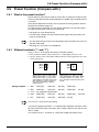
Preset Function (Compare with:) ...................................................................................19
What is the preset function? ........................................................................................................................... 19
Wildcard symbols (“!” and “?”) ........................................................................................................................ 19
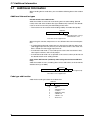
Additional Information ....................................................................................................20
Max. Code Length (Designated Digit )
Output Function ...............................................................................................................22
96M1125
iii
Chapter 3: Setup Software
Controlling the BL-500 .................................................................................................... 24
Setup Software Requirements ....................................................................................................................... 24
Operating Procedure ...................................................................................................... 26
Outline of Operation ....................................................................................................................................... 26
Setup Software Operating Procedure ........................................................................... 27
File Operation ................................................................................................................................................ 28
Main setting screen ........................................................................................................................................ 30
CODE39 setup ............................................................................................................................................... 31
ITF setup ........................................................................................................................................................ 32
Setup for Industrial 2 of 5 and COOP 2 of 5 .................................................................................................. 32
Codabar setup ............................................................................................................................................... 33
UPC/EAN setup ............................................................................................................................................. 34
CODE128 setup ............................................................................................................................................. 34
Timing setting ................................................................................................................................................. 35
Communication setting .................................................................................................................................. 36
Communication strings setup ......................................................................................................................... 36
Other setting .................................................................................................................................................. 37
Sending Settings ............................................................................................................................................ 38
Version Display .............................................................................................................................................. 38
List of Error Messages ................................................................................................... 39
How to Use Terminal Software ...................................................................................... 40
Chapter 4: Serial Communication (RS-232C/RS-422A)
Serial Communication .................................................................................................... 44
Communication Setup .................................................................................................................................... 44
Details on Data Communication .................................................................................... 45
Communication Protocols (Hardware handshaking) ...................................................................................... 45
Capacity of Transmission Buffer .................................................................................................................... 46
Read Data Format ......................................................................................................................................... 46
Read Error Code ............................................................................................................................................ 47
Command Communication ............................................................................................ 48
Setup of Direct Control Commands ............................................................................................................... 48
Explanation of Direct Control Commands ...................................................................................................... 49
Details on Parameter Setting Commands ...................................................................................................... 50
Response Error Code .................................................................................................................................... 52
Description of Parameter Setting Commands ................................................................................................ 52
Appendix
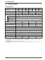
Specifications .................................................................................................................. 60
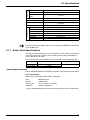
Raster Scan Specifications ............................................................................................................................ 61
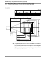
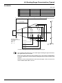
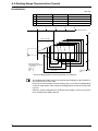
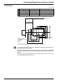
Reading Range Characteristics (Typical) ..................................................................... 62
Angular Characteristics (Typical) .................................................................................. 66
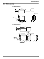
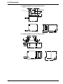
Dimensions ...................................................................................................................... 67
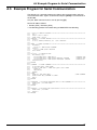
Example Program for Serial Communication ............................................................... 69
Troubleshooting .............................................................................................................. 70
CODE128 Specifications ................................................................................................ 72
ASCII Code Table ............................................................................................................ 73
Default Settings ............................................................................................................... 74
iv
BL-U1 Power Supply
Introduction ......................................................................................................................80
Conventions .....................................................................................................................80
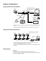
System Configuration .....................................................................................................81
Using the RS-232C and RS-422A .................................................................................................................. 81
Using the RS-485 multidrop link ..................................................................................................................... 81
Other Options ................................................................................................................................................. 81
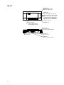
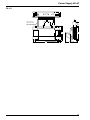
BL-U1 ............................................................................................................................................................. 82
BL-U1 Connections .........................................................................................................83
Connecting the AC power supply ................................................................................................................... 83
Connecting the BL-U1 to a BL series ............................................................................................................. 83
Setting the BL-U1 DIP switches ..................................................................................................................... 84
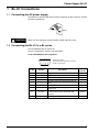
Function and wiring on the I/O terminal block ................................................................................................ 85
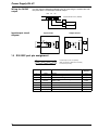
RS-232C port pin assignment ........................................................................................................................ 86
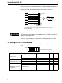
RS-232C port wiring ....................................................................................................................................... 87
RS-422A port wiring ....................................................................................................................................... 87
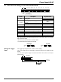
Wiring the RS-485 (multidrop link) ................................................................................................................. 88
Installation ........................................................................................................................89
Precautions before use .................................................................................................................................. 89
Installing the BL-U1 ........................................................................................................................................ 90
Outline of Multidrop Link ................................................................................................91
Multidrop Link ................................................................................................................................................. 91
System Configuration ..................................................................................................................................... 91
Setup and Connection Procedures ................................................................................92
Communication ................................................................................................................93
Outline of Communication types .................................................................................................................... 93
Communication Format .................................................................................................................................. 93
Details on Data Communication ..................................................................................................................... 95
Details of Command Communication ............................................................................................................. 97
Precautions for Programming ........................................................................................99
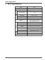
BL-U1 Specifications .....................................................................................................100
WARRANTIES .................................................................................................................103
v
vi
Safety Precautions
This User’s Manual describes the operation and functions of the BL-500. Read
this manual carefully to ensure safe use and maximum performance from your
BL-500.
The BL-500 uses a semiconductor laser as the light source. Before using the
product, see “Laser Safety Precautions” on page 3 to learn the safe and correct
method of using the reader.
Symbols
The following symbols alert you to important messages. Be sure to read these
messages carefully.
WARNING
Failure to follow instructions may lead to injury. (electric shock, burn, etc.)
CAUTION
Failure to follow instructions may lead to product damage.
Note
Provides additional information on proper operation.
Any reference to the BL-500 in this manual refers to information on all products in
the BL-500 series. When refering to specific product information, the product
name exclusively will be used.
General precautions
• The BL-500 uses a semiconductor laser as the light source. Before using the
product, see “Handling a Laser Product” on page 3 to learn the safe and correct method of using the reader.
• Do not use the BL-500 as a controller for equipment which could potentially
harm a person.
• Be sure to match the polarities (+ and -) of the power supply when soldering
the connections. Reversing the polarities will damage the unit.
• Do not disassemble the BL-500. Doing so may make repair impossible.
• The BL-500 is a precision instrument. Dropping the unit could damaged it.
Exercise caution when moving or installing.
• Be sure that there is no water, oil or dust on the optical pickup. Such obstructions can cause read errors. Clean the pickup by gently wiping with a soft lens
cloth soaked with water.
vii
Laser Safety Precautions
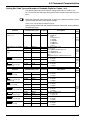
Classification
Model
BL-500(H)
BL-501(H)
BL-550(H)
FDA (CDRH)
Class II
IEC/EN 60825-1:1993 +A2:2001
Class 2
DIN EN 60825-1 2001
Klasse 2
BL-551(H)
Warning labels
FDA (CDRH) Class II
BL-500/501/500H/501H
BL-550/551/550H/551H
AVOID EXPOSURE
Laser radiation is emitted
from this aperture.
CAUTION
CAUTION
Laser radiationDo not stare into beam.
Las er radiationDo not s tare into beam.
Semic onduc tor las er
Max imum output
Puls e duration
Clas s II las er product
670nm
1.2mW
70μsec
CAUTION-Las er radiation when
open. Do not s tare into beam.
Semiconductor laser
Maximum output
Pulse duration
Class II laser product
670nm
1.2mW
70μsec
CAUTION-Laser radiation when
open. Do not stare into beam.
IEC/EN 60825-1 Class 2
BL-500/501/500H/501H
BL-550/551/550H/551H
CAUTION
LASER RADIATION
WHEN OPEN. DO NOT
STARE INTO BEAM.
DIN EN Klasse 2
BL-500/501/500H/501H
BL-550/551/550H/551H
VORSICHT
LASERSTRAHLUNG
WENN ABDECKUNG
GEOFFNET. NICHT IN
DEN STRAHL BUCKEN.
Aperture label
FDA Class II
CAUTION – Laser radiation
when open.
Do not stare into beam.
AVOID EXPOSURE
Laser radiation is emitted
from this aperture.
viii
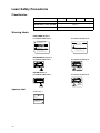
Label location
The following label positions are recommended.
FDA Warning labels are attached to the sensor head as shown below. The IEC/
DIN Warning labels are packaged with the BL-500 series. Affix the Warning labels
on the sensor head as shown below.
FDA (CDRH)
BL-500/501/500(H)/501(H)
BL-550/551/550(H)/551(H)
2)
1)
1)
ION
UT
CA
ION
UT
CA
IEC
BL-500/501/500(H)/501(H)
1)
BL-550/551/550(H)/551(H)
2)
1)
3)
Safety consideration
CAUTION
Use of controls or adjustments or the performance of procedures other than those
specified herein may result in hazardous radiation exposure.
The laser beam is not harmful to the skin. There is, therefore, no danger in exposing arms or hands to the beam. The only possible health hazard is in exposing the
eyes to the laser beam. Damage to the eyes can occur if the operator stares directly into the beam.
Following the safety precautions below to ensure operator safety:
• Operate the BL-500 series only according to the procedures described in
this instruction manual.
Otherwise, injury may occur due to exposure to the laser beam.
• Do not disassemble the sensor head.
Laser emission from the BL-500 series is not automatically stopped if the sensor head is disassembled. If you disassemble the sensor head for inspection or
repair, you may be exposed to the laser beam. If the BL-500 series malfunctions, contact KEYENCE immediately.
• Do not look directly at the laser beam.
Looking directly at the laser beam may result in serious eye injury.
• Protective enclosure
We recommend that you install a protective enclosure around the sensor head
to prevent any person from getting near the sensor head during operation.
• Protective goggles
We recommend that you wear protective goggles when using the BL-500
series.
• Stop laser emissions before cleaning the laser emission port.
Failure to stop the laser emission may expose eyes to the laser beam.
• Check the laser beam path.
To prevent exposure to the laser beam due to specular or diffuse reflection,
install a screen which offers the appropriate reflectance and temperature characteristics to interrupt the reflected laser beam. Do not install the BL-500
series in such a way that the laser beam passes at eye height.
ix
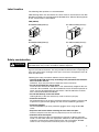
Safety features
The BL series is provided with the following safety features. Make sure these features function correctly before making any measurement.
1. LASER ON alarm LED
A visible LED that informs you that the laser beam is being emitted, or is about to
be emitted, at least 3 seconds after power is provided to the amplifier and the sensor head.
2. Laser emission delay
Laser emission only starts when the LED has been ON/lit for at least 3 seconds,
thus decreasing the possibility of laser exposure.
3. Laser Stop function
By sending the laser stop command (see page 18) to the BL-500, you can disabled laser emission. When working near the laser pickup, use the laser can disabled laser emission. When working near the laser pickup, use the laser stop
command to protect you from direct exposure to laser beam. When this command
is activated, the top LED of the STABILITY LEDS blinks.
How to use the Laser Stop command
Laser stop mode can be invoked by transmitting the serial command from the host
computer to the unit.
To execute the Laser stop command, use the following instruction.
LOCK [CR]
To cancel Laser stop, use the following instruction.
UNLOCK [CR]
When either above instruction is properly processed, the BL-500 series returns
the following message to the host computer.
OK [CR]
Unpacking
There are two packages: A BL-500 package and a software package.
Each package contains the following components. Be sure to check the items
against the checklist below:
BL-500 package
BL-500 unit
1
Mounting bracket
1
Mounting bracket screw (32 mm)
2
Laser warning label
1
Instruction manual
1
Setup software (BL-50H1E) and user’s manual
Note
x
Setup software floppy disk (3.5-inch)
1
User’s Manual (this document)
1
The setup software and user’s manual are not included in the BL-500 package.
You can order the software package, free of charge, separately.
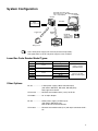
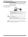
System Configuration
RS-232C null modem cable
OP-22149 (1.5 m) + OP-25057 IBM PC/AT
or compatible
(25- to 9-pin adapter)
BL-500
RS-232C
5VDC
Power-supply unit*
OK/NG
output
Trigger input
Timing sensor
Note
BL-50H1E
Setup software
3.5-inch version
WINDOWS 3.1
PLC etc.
The 5 VDC power supply unit must be purchased separately.
The optional BL-U1 or BL-U2 power supply is also available.
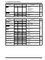
Laser Bar-Code Reader Model Types:
Model
BL-500
BL-501
BL-550
BL-551
BL-500H
BL-501H
BL-550H
BL-551H
Reading direction
Scanning method
Front
Side
Front
Side
Single
Raster
Single
Raster
Single
Raster
Single
Raster
Readable bar width
0.25 to 1.0 mm
(Standard type)
0.125 to 0.5 mm
(High-resolution type)
The readable bar width is the range in which narrow-group bar codes can be read.
Other Options
BL-U1: .................. 5 VDC power supply (100 to 240 VAC input)
(with built-in RS-232C, RS-422A, RS-485 ports)
See page 79 for details.
OP-22149: ........... RS-232C null modem cable (1.5 m) for BL-U1
OP-25057 ............. 25- to 9-pin adapter
BL-U2: .................. 5VDC power supply (24 VDC input)
(with built-in RS-232C port)
See the BL-U2 manual for details.
OP-27937: ........... RS-232C null modem cable (2 m) with 9-pin connector for BLU2
xi
Parts and Functions
BL-500/501/500H/501H
STB
OK/NG
TIMING
LASER ON
STABILITY LED
Indicates the reading stability or
the unit’s operation status (see P.
33 to P. 34).
Optical pickup
Laser
light source
OK/NG LED
OK output: Lights in green
NG output: Lights in red
TIMING LED
Lights when the timing input turns
ON.
LASER ON LED
Lights when the laser turns ON.
Cable (2 m)
BL-550/551/550H/551H
Optical pickup/
light source
For LED names, see the BL-500/501(H) User’s Manual.
xii
Chapter 1
Connection and Installation
1.1 BL-500 Connections
1.1 BL-500 Connections
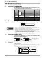
1.1.1 Wire colors and signal types
The following wires extend from the BL-500. Solder the required wires to a connector to connect the BL-500 to a computer/controller.
Wire Color
Symbol
Description
Shield
Purple
Brown
Pink
Blue
Shield
RS-232C SD (TXD)
RD (RXD)
RS (RTS)
CS (CTS)
Black
GND (SG)
Yellow
White
Gray
Red
TIM
OK
NG
+ 5V
Signal Direction
Connect to ground (SG)
Send data
Receive data
Request to send (always on)
Request to receive
Ground (common ground for
respective signals)
Trigger input
OK output
NG output
+ 5V power supply input
——
Output
Input
Output
Input
——
Input
Output
Output
Input
1.1.2 Power supply wiring
BL-500
CAUTION
+5V
Red
GND
Black
+
5 VDC
• Be sure to match the polarities of the power supply when soldering the connections. Reversing the polarities will damage the unit.
• Make sure that the power supply provides a stable 5 VDC ± 5%. If the power
supply does not function in the above range, it can damage the unit.
• Do not use a power cable longer that 2 meters. A long power cable can cause
a voltage drop, preventing the BL-500 from starting properly.
• If the power supply is UL rated, it must provide Class 2 output.
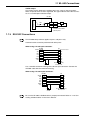
1.1.3 Connecting shielded cables
For optimum reading performance, connect the BL-500’s shielded cable to GND
(black) directly or through a condenser.
BL-500
BL-500
Shield
—
Shield
—
Black
GND
Black
GND
Ceramic capacitor
(Withdraw voltage 0.5 k to
1.0 kVDC, Capacity 0.1 μF,
non-polarity)
• Using a capacitor provides a more stable operation.
1.1.4 Wiring I/O
Trigger (TIM) input
The trigger input is used to signal the BL-500 to start reading (Start laser emission).
The trigger input is a non-voltage input (TTL input is also available).
10KΩ
5 VDC
2
4.7
KΩ
TIM
Yellow
GND
Black
1.1 BL-500 Connections
OK/NG output
This output signals whether the readout data is the same as the preset data.
When no preset data has been registered, the signal indicates bar code read status. It is an NPN open-collector output.
Internal circuit
BL-500
1kΩ
OK/NG
Write/Gray
GND
Black
Load
+
*Rated load: 24 VDC
(30 mA) max.
1.1.5 RS-232C Connections
Note
This BL-500 setup software applies to port 1 and port 2 only.
Communication cannot be performed with other ports.
When using a D-sub 9-pin connector:
Shield
SD
RD
CS
RS
GND
+5V
BL-500
Shield
Purple
Blown
Blue
Pink
Black
Red
+
5 VDC
PC
– Connector case
2 RD
3 SD
7 RS
8 CS
5 SG
4 ER
6 DR
D-sub 9-pin (male)
# 4-40 screw
Use a metallic connector housing for the D-sub 9-pin connector. Connect the
shielded cable with the connector housing.
When using a D-sub 25-pin connector:
Shield
RD
SD
CS
RS
GND
+5V
BL-500
Shield
Blown
Purple
Blue
Pink
Black
Red
+
5 VDC
Note
PC
1 FG
2 SD
3 RD
4 RS
5 CS
7 SG
6 DR
20 ER
D-sub 25-pin (male)
M 2..6 screw
Be sure the BL-500’s shielded cable is properly connected. Refer to “1.1.3 Connecting shielded cables” in the User’s Manual.
3
1.1 BL-500 Connections
Hints on correct use
Trigger (TIM) input
Set the trigger input to be long enough to allow the laser beam to cover the entire
bar code.
If the trigger input needs to be on for only a short period of time, select one-shot
mode.
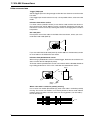
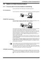
Influence from mirror surface
If a mirror surface (metallic surface) is near the bar code and the laser beam reflects off the mirror, the BL-500 may cause a read error. Protect the unit from the
influence of a mirror surface by covering the surface or changing the bar code label position.
Bar code pitch
Do not place several bar codes in the field of the laser beam, unless you are in
multi-label read mode (Multi 3).
If you use multi-label read mode (multi 3), the BL-500 can simultaneously read 2
to 4 bar codes in the field of the laser beam.
Influence from photoelectric sensor
When using a photoelectric sensor to control trigger, block the sensor beam so it
does not enter the BL-500 optical pickup.
The beam from the photoelectric sensor can interfere with the BL-500, deteriorating reading performance. If this case, reposition the photoelectric sensor.
Object
Bar code
Light
source
Optical
pickup
When a bar code is stained or partially missing
Use a raster scan reader (BL-501/551(H)) when a bar code is stained or partially
missing. This raster scan readers scan several portions of the bar code. Normal
portions of the bar code, even with stained or missing portions, can be read by
the BL-501/551(H).
Scans
4
1.2 Installing the BL-500 Series
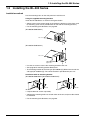
1.2 Installing the BL-500 Series
Installation method
Use the mounting holes on the side panel to install the unit.
Using the supplied mounting brackets
Install the BL-500 Series as shown in the figures below.
• Select screws of the proper length by checking the thickness of the plate used
for mounting. (The screws provided are for use with the mounting bracket.)
• For the mounting hole diameter, see page 66.
(BL-500/501/500H/501H)
M3 screws
(BL-550/551/550H/551H)
M3 screws
Optical pickup/
light source
• Use the set screw to secure the mounting bracket to the unit.
• See page 68 for mounting bracket dimensions.
• The mounting bracket for the front type (BL-500/501(H)) differs from that for the
side type (BL-550/551(H)). The correct bracket is provided with your unit.
Installation with no mounting bracket
(BL-500/501/500H/501H)(BL-550/551/550H/551H)
M3 nuts
M3 nuts
M3 screws
M3 screws
• Prepare M3 male screws separately.
• Although the mounting holes are on both sides of the unit, only one side should
be mounted.
• For the mounting hole diameter, see page 66.
5
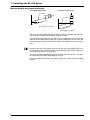
1.2 Installing the BL-500 Series
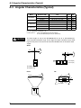
Mounting angle and mounting distance
BL-500/501/500H/501H
BL-550/551/550H/551H
0
BL-50
Laser beam
BL-550
Laser beam
15°
ce
istan
ing d
Read
*Reading distance = 120 mm
15°
ce
istan
ing d
d
a
e
R
*Reading distance = 95 mm
Set the angle and reading distance by referring to the read range characteristics
and angle characteristics described on page 62 and 66.
The allowable reading distance and angle may vary depending on the narrow bar
width of the bar code, the bar code size, and the readability of the bar code. Set
these parameters after performing a test read of the required bar code using the
unit.
Note
Do not set the unit at an angle at which the laser beam is perpendicular to the surface of the bar code. The beam will be fully reflected into the reader, making correct reading impossible (see page 66).
The laser radiation angle differs between the front and side type units. The optimal mounting angle differs depending on the type.
The reading check test mode (see page 15) allows you to set the optimal reading
position.
6
Chapter 2
Functions for Reading Operation
2.1 Read Operation
2.1 Read Operation
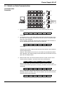
2.1.1 Scanning method
There are two methods for triggering the BL-500 to read bar codes; the “Level signal” method and the “One-shot signal” method. The example given for these two
methods uses the “single label read mode” (see page 10), which reads one bar
code while trigger input turns on once, and uses the “after read” as the data-send
mode (see page 9).
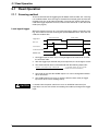
Level signal trigger
When the trigger input turns on, laser emission begins and the unit begins reading. The laser turns off after reaching the specified decode count. Then, the unit
sends the readout data.
<Succeed to read>
Trigger input
<Fail to read>
*1
Bar code
Laser beams
*2
Communication time
*3
OK/NG output
OK/NG *4
NG
*5
1. Set trigger input so that it stays on long enough for the laser beam to cover
the entire bar code.
2. After the trigger input exceeds the preset input time, the laser begins to emit.
3. The communication time can be obtained from the following expression:
Data bits + (1: If parity is used) + Start/stop bit
Baud rate
X (code length of data to be sent + Header/
number of characters in delimeter)
4. The length of time that the OK/NG output is on can be changed to between
10 ms and 2.55 s.
5. The OK/NG output turns on 5 ms after the data has been read (or trigger
input turns off in case of reading failure).
CAUTION
8
5 seconds after the power switch turns on or an UNLOCK command (see
page 50) is sent, the unit will not start reading a bar code by turning on the trigger
input.
2.1 Read Operation
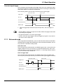
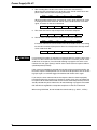
One-shot signal trigger
The unit detects the rising edge of the trigger input and starts reading bar codes
for the preset input time. The laser beam turns off after reaching the specified decode count and the unit sends the readout data.
The remaining actions are the same as those for level signal trigger.
Trigger input
<Succeed to read>
*1
<Fail to read>
Bar code
Preset input time
Preset input time
Laser beams
Communication time
OK/NG
OK/NG output
NG
1. After the trigger input exceeds the preset input times, the laser begins to
emit.
Note
• The BL-500 can read up to 4 types of bar codes without changing the bar code
type setting (see page 30).
• For general operation, see "Level signal trigger"
• Choose “One-shot signal trigger” when the trigger input signal is very short or
you want to set the input time.
2.1.2 Data-send mode
In the single label read mode only, you can select from the two data send modes
(OK/NG output on trigger) described below: In the multi-label read mode, you can
only select the “send after reading” mode.
Send after read
The unit outputs the communication and OK/NG signals after a successful read
(trigger output turns on as many times as the preset decode count). This is the
same operation as in the time chart described in “1.1 Scanning method”. Normally, this is the method you should use.
Send at trigger input
The unit outputs the communication and OK/NG signal when the trigger input
turns off (or the preset input time has passed if one-shot signal trigger is selected).
<Fail to read>
<Succeed to read>
Trigger input
Bar code
Laser beams
Communication time
OK/NG output
OK/NG
NG
9
2.2 Read modes
2.2 Read modes
The BL-500 provides 4 types of read modes.
2.2.1 Single label read mode
This mode allows the unit to read one bar code during one trigger input signal.
The operation and timing chart are described on page 8.
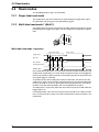
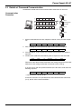
2.2.2 Multi-label read mode 1 (Multi 1)
This mode allows the unit to read several bar codes printed on one label as shown
below during one trigger input signal. The unit outputs the readout data sequentially.
BL-50
0
STB
OK/N
G
TIMIN
G
LASER
ON
Multi-label read mode 1 operation
<Succeed to read>
<Fail to read>
Trigger input
Repeat reading time
Bar code
Laser beams
Communication time
OK/NG output
OK
OK
OK
OK
NG
In the multi-label read mode 1, the unit reads several bar codes continuously, and
outputs them sequentially as it reads while laser beam remains on and trigger input turns on after bar codes have been read (or during the preset input time if oneshot signal trigger is selected).
To prevent the unit from reading the same bar code twice, the time for one bar
code to pass across the laser beam’s field and read, plus the repeat reading time
must be set (100 ms to 25.5 s). During the repeat reading time, the unit cannot
read the same bar code repeatedly, but can read different bar codes.
A reading error is issued only when the unit cannot read any bar code while the
trigger input is on.
For OK/NG output, “OK” turns on every time the unit reads a bar code and “NG”
turns on if the unit fails to read a bar code. (Comparison to the preset data is not
performed.)
10
2.2 Read modes
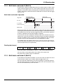
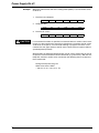
2.2.3 Multi-label read mode 2 (Multi 2)
As with multi 1 mode, this mode allows the unit to read several bar codes continuously while the trigger input is on. (The number of bar codes that can be read
depends on the buffer capacity. See page 46.) The difference between the two
modes is that multi 2 mode sends all the readout data at one time after the trigger
input turns off.
Multi-label read mode 2 operation
<Succeed to read>
Trigger input
<Fail to read>
Repeat reading
time
Bar code
Laser beams
Communication time
OK
OK/NG output
NG
Multi 2 mode allows the unit to read several bar codes while the trigger input is on
(or during the preset input time if one-shot signal trigger is selected) and sends all
the readout data at one time after the trigger input turns off (or after the preset input time is expired if one-shot signal trigger is selected).
To prevent the unit from reading the same bar code twice, the time for one bar
code to pass across the laser beam’s field and read, plus the repeat reading time
must be set (100 ms to 25.5 s). During the repeat reading time, the unit cannot
read the same bar code repeatedly, but can read different bar codes.
For OK/NG output, after trigger input turns off, “OK” turns on if the unit reads at
least one bar code and “NG” turns on if the unit fails to read a bar code. (Comparison to the preset data is not performed.)
Reading data format
Header
1st
data
,
2nd
data
,
3rd
data
,
4th
data
,
Delimeter
Each data packet is separated by a comma (, : 2CH) (intermediate delimiter).
The unit sends as many data packets the number of bar codes read.
See page 46 for “header string” and “delimeter”.
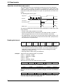
2.2.4 Multi-label read mode 3 (Multi 3)
As described in multi-label read modes 1 and 2, this mode also allows the unit to
read several bar codes (up to 4 codes) while the trigger input is on.
The unit sends the readout data at one time according to a specified sequence
after the trigger input turns off. When up to 4 codes are in the laser beam’s field,
the unit can simultaneously reads all of them.
11
2.2 Read modes
Operation of multi-label read mode 3
This mode allows the unit to continuously read each one of 4 bar code types
“Code 1”, “Code 2”, “Code 3”, and “Code 4” as specified in the “code setup” of the
setup software (see page 30). If 3 types are specified in the “code setup”, the unit
reads 3 bar codes (each of 3 types). If 2 types are specified, the unit reads 2 bar
codes.
The following time chart is given.
Trigger input
Bar Code
Code 1 Code 2 Code 3 Code 4
Laser beams
Code 4
Code 3
Code 2
Code 1
Communication time
OK
OK/NG output
NG
The above example chart is with all four codes specified in the “code setup” of the
setup software.
• The bar code reading sequence is not fixed.
• The unit communicates the readout data in the order of Code 1 to Code 4.
After the trigger input turns off, the unit sends all the data at one time.
• For OK/NG output, “OK” turns on if the unit reads all the specified Codes 1 to 4
and “NG” turns on if the unit fails to read at least one bar code. (Comparison to
the preset data is not performed.)
Reading data format
Header
Data read
from Code
1
,
Data read
from Code
2
,
Data read
from Code
3
,
Data read
from Code
4
,
Delimeter
• Each data packet is separated by a comma (, : 2CH) (intermediate delimiter).
• If an read error occurs on any one of Codes 1 to 4, or the corresponding bar
code does not exist, “ERROR” (see page 47 for the reading error codes),
instead of the read data is sent.
• See page 46 for “header string” and “delimeter”.
Example
Suppose that the following codes are specified:
Code 1 --- CODE39, 10 digits
Code 2 --- EAN/UPC, 13 digits
Code 3 --- None
Code 4 --- CODE39, 8 digits
When the unit successfully reads all 3 types of codes:
Header
ABCDE12345
,
4901234567894
,
KEYENCE
Delimeter
KEYENCE
Delimeter
When the unit fails to read Code 1 (CODE39, 10 digits)
Header
ERROR
,
4901234567894
,
When the unit fails to read Code 1 (CODE39, 10 digits) and Code 4 (CODE39, 8
digits)
Header
ERROR
,
4901234567894
,
ERROR
Delimeter
When the same type of data having the same digits is specified to all Codes 1 to
4, the unit sends the data in the reading order.
12
2.2 Read modes
Example
Suppose that the following codes are specified:
Code 1 --- CODE39, 7 digits
Code 2 --- CODE39, 7 digits
Code 3 --- CODE39, 7 digits
Code 4 --- CODE39, 7 digits
Header
Note
ABCD123
,
XYZ3333
,
1234567
,
KEYENCE
,
Delimeter
The unit cannot read the bar code having the same content twice while trigger input turns on once.
13
2.3 Label orientation mode
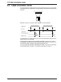
2.3 Label orientation mode
As shown below, this mode allows the unit to read bar codes only in the specified
orientation when bar code labels are moving both in the forward and reverse orientations.
Forward orientation Reverse orientation
4 9000000
4 9000000
Normally, the unit can read bar codes regardless of the orientation.
<Specified orientation>
<Non-specified orientation>
Trigger input
Bar code
Laser beams
Communication time
OK/NG output
OK/NG
NG
An reading error is issued when the unit reads a bar code label running in the orientation which is not specified.
The above chart applies to the single label read mode. You can also use this
mode together with the desired multi-label read mode. However, in any case, the
unit reads bar codes running in the specified orientation only.
You can specify the orientation individually for Codes 1 to 4, such as specifying
“forward orientation” for Code 1, and “reverse orientation” for Code 2.
14
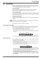
2.4 Test Mode
2.4 Test Mode
Test mode can be used for the bar code reading test. Because trigger input is not
required, this mode allows you to perform a reading test easily. You can select
one of the following 3 methods to enter the test mode.
Send the command
Enter test mode by sending the serial command for the test mode (TEST1,
TEST2). Commands should be entered in all uppercase characters.
Turning on trigger input
You can use the BL-500 to switch to test mode by turning on the trigger input (see
page 35). If you select this method to enter the test mode, trigger input is disabled
to ensure normal operation.
Turning on power supply
You can set the BL-500 to enter test mode by turning on the power supply (see
page 35).
Note
When you try to enter the test mode by turning on trigger input, you cannot use
the serial command to enter the test mode.
The following 2 types of test modes are available:
Reading rate check mode
The unit scans a bar code100 times and analyzes how many times it can decode
the scanned data (reading rate). This mode is useful in the following cases:
• When adjusting the mounting distance and angle
• When verifying the reading stability of the bar code to be used
• The analyzed result will be output anytime (every 100 scans) using the following format:
Delimiter
Readout data
:
m
%
m = 0 to 100 (zero-suppressed)
• Although an OK/NG signal is not output, the OK/NG LED lights (see page 17).
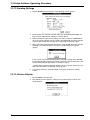
Tact check mode
In this test mode, the unit counts how many scans can be decoded (the decode
count) while reading one bar code.
This mode is useful when testing which line speed can be expected when actually
implementing the BL-500 system on the line.
• The analyzed data is output using the following format 0.2 seconds after the
bar code has passed the laser beam’s field.
Delimiter
Readout data
:
m
m = 1 to 999 (zero-suppressed)
• The unit continues to read a bar code while the code is in the laser beam’s field
and does not output the result. If the laser beam does not detect a bar code for
0.2 seconds, the unit stops scanning and outputs the result.
• If the unit reads the same bar code twice within the 0.2 seconds, the unit cannot separate the bar codes and will add to the read count. However, the unit
can continuously reads different bar codes within the 0.2 seconds by recognizing the delimiter.
15
2.4 Test Mode
• The read count can be up to 9999.
• Although an OK/NG signal is not output, the OK/NG LED lights (see page 17).
Note
When the unit is running in test mode, the laser beam remains on, which can
shorten the laser’s service life.
Select the test mode only when you need to perform a test read.
Avoid long emission times.
When using the “additional information” (see page 20 to 21) in the test mode, the
selected data is added in the same manner as in the normal operation mode.
However, only when selecting the reading rate check mode, the decode count
and scan count are not added to the analyzed results.
16
2.5 STABILITY LEDs
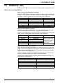
2.5 STABILITY LEDs
STABILITY LEDs allow you to easily check reading stability and operation status.
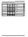
Indication of reading stability
When reading rate check mode is selected
STABILITY LEDs light according to the reading rate shown in the table below. Although, in the test mode, the unit does not output an OK/NG signal, the OK/NG
LED lights as below. (Comparison to the preset data is not performed.)
Reading rate
STABILITY LED
OK/NG LED
81 to 100%
61 to 80%
41 to 60%
21 to 40%
1 to 20%
0%
5 LEDs light
4 LEDs light
3 LEDs light
2 LEDs light
1 LED lights
——
Green
Green
Green
Green
Green
Red
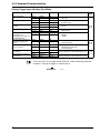
When tact check mode is selected
STABILITY LEDs light according to the scan count (decode count), which indicates the number of successful reads, as shown in the table below.
Although, in the test mode, the unit does not output an OK/NG signal, OK/NG LED
lights as below. (Comparison to the preset data is not performed.)
Decode count
STABILITY LED
OK/NG LED
100 or more
50 to 99
10 to 49
5 to 9
1 to 4
0
5 LEDs light
4 LEDs light
3 LEDs light
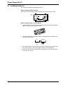
2 LEDs light
1 LED lights
——
Green (decode counts are
equal to or greater than
the preset match count)
Red (decode counts are
less than the preset
match count)
Red
When normal read mode is selected
When you select multi-label read mode 1 or 2 (see page 10 to 11), or the send
mode is set to “after trigger input” (see page 9), or you select the decode count
adding function (see page 20), STABILITY LEDs light according to the decode
count as shown in the table below.
However, If you do not select “use STABILITY LED” in the setup software (see
page 37), STABILITY LEDs do not light in normal read mode.
ON/NG output (ON/NG LED) turns on/off normally according to the result of a
comparison to the preset data.
Decode count
STABILITY LED
100 or more
50 to 99
10 to 49
5 to 9
1 to 4
0
5 LEDs light
4 LEDs light
3 LEDs light
2 LEDs light
1 LED lights
——
17
2.5 STABILITY LEDs
Unit operation status display
STABILITY LEDs indicate the following information in addition to reading stability.
Power-on
LEDs turn on sequentially from the bottom. The unit cannot read bar codes while
STABILITY LEDs are lit (for 5 seconds).
During setup (see page 49)
All the STABILITY LEDs blink.
Using “Laser stop” function (by sending LOCK; see page 50)
The top LED blinks. When resetting “laser stop” (by sending UNLOCK), the LEDs
light in the same manner as at power-on.
Unit error
The 2nd or 3rd LED from the top blinks. The unit may have failed. Contact your
nearest KEYENCE office or distributor.
18
2.6 Preset Function (Compare with:)
2.6 Preset Function (Compare with:)
2.6.1 What is the preset function?
The BL-500 can store one bar code as preset data. It compares the preset data
to the bar code data actually read and outputs an OK/NG signal to whether there
is a match.
Using the BL-500 preset function, you can prevent the wrong products from entering the line without using a PC.
If no preset data is registered, the unit outputs OK when it successfully reads a
bar code and NG when it fails to read a bar code.
• See page 8 to 14 for output timing.
• Use the setup software and serial command to register the preset data (see
page 37 and page 58).
Note
• The bar code actually read can be compared to the preset data only in the single label read mode.
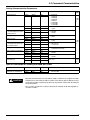
• See page 72 if you want to use CODE128.
2.6.2 Wildcard symbols (“!” and “?”)
Using “!” and “?” in the preset data allows for flexible settings.
?: Does not define numeric values (characters) of certain digit(s) of the bar code.
!: Ignores numeric values and symbols within the dot box and recognizes the bar codes
as the same group.
4912 3 4 5 6
4912 5 2 5 6
4912 AB 5 6
When using “?” data as “4912??56”, 2
digits positioned in “??” can contain
any numeric values (or characters),
expanding the allowable range. Identifies all the bar codes to be OK as
long as the beginning or ending
strings match.
Setting examples
4912 3 4 5 6
4912 C
4912
When using “!” as “4912!”, any bar
code which begins with “4912” will be
OK. When using “!” as “!4912”, any
bar code which ends with “4912” will
be OK.
1. “ABC?”
ABCD (OK),
ABC3 (OK),
ABC (NG),
ABCDE (NG)
2. “ABC!”
ABCD (OK),
ABC3 (OK),
ABC (OK),
ABCDE (OK),
AB (NB)
ABBDE (NG),
ADE (NG)
3. “?????” Any 5-digit bar code will be OK.
Note
4. “!CDE”
ABCDE (OK),
3CDE (OK),
CDE (OK),
5. “A!E”
ABCDE (OK),
A3CE (OK),
ABCD (NG), AE (OK)
You can use “!” only once in the setting.
If you do not register preset data, “!” is automatically registered. Therefore, when
the unit successfully reads a bar code, “OK” is output; when the unit fails to read,
“NG” is output.
You cannot use the “*” character as a wild card symbol with the BL series.
19
2.7 Additional Information
2.7 Additional Information
When sending the bar code data, you can add the following data to the readout
data.
Additional information types
Decode match count add function
Adds the number of successful scans during one bar code reading (decode
count) to the end of the readout data (up to 9999 count). However, this decode
count is never less than the preset decoding match count.
• This function can be used to check reading stability and code label quality.
Delimiter
:
Readout data
d
d = [Decoding match count] to
9999: Decode count
The value is zero-suppressed.
When using this function, output turns on at a different time from normal operation.
• In single label read mode, output turns on after one bar code has been read
(after trigger input turns off). Even if you set the data-send to “after read”, the
data is forced sent after trigger input turns off.
• In multi-label read mode 1, a bar code passes across the laser beam’s field,
after repeat read time, and is finally output.
• In multi-label read mode 2 or 3, operation is the same as when you do not use
the decode match count adding function.
Scan count add function (valid only when using the read count add function)
Adds the number of scans, including when no bar code exists, to the end of the
decode count (up to 9999).
Delimiters
:
Readout data
d
/
s
m = 1 to 999 (zero-suppressed)
The value is zero-suppressed.
Code type add function
Adds the bar code type before the readout data.
Delimiter
t
t=0
1
2
3
4
5
6
7
20
:
Readout data
:Code39
:ITF
:Industrial 2 of 5
:Codabar
:EAN/UPC (A•E)
:CODE 128
:COOP 2 of 5
:Read error
2.7 Additional Information
label orientation add function
Adds the orientation of bar code travel before the readout data.
Delimiter
:
r
r =F
R
Readout data
:Forward
:Reverse
If
Forward orientation Reverse orientation
4 9000000
4 9000000
Order of additional information
If you select to include all the additional information functions, they appear in the
following order:
Code type
Note
:
label
orientation
:
Readout data
:
Decode match
count
:
Scan count
You can change the delimiter as desired (one character), except the delimiter of
the scan count.
21
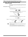
2.8 Max. Code Length (Designated Digit) Output Function
2.8 Max. Code Length (Designated Digit)
Output Function
This function allows you to output the designated digit(s) as desired from the readout bar code data. For example, from bar code data “49123456”, you can extract
“1234” for output.
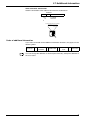
Setting digits to be output
Set the digits to be output as shown below. Individually set the digits for codes 1
to 4.
1. Set the direction to designate.
Set from which direction you want to start counting.
Forward
Reverse
4 9 1 2 3 4 5 6
2. Set how many digits you want to designate for output starting from the designation start digit in (2) (designation effective digits).
3 digits starting from 5th digit by counting forward
4 9 1 2 3 4 5 6
The actual setting order is (1) (3) (2).
3. Set from which digit you want to begin designation (destination start digit).
5th digit by counting forward
4 9 1 2 3 4 5 6
Example
Designating and outputting “34” from bar codes “158423421” and “58423421”
1 5 8 4 2 3 4 2 1
5 8 4 2 3 4 2 1
Designate 2 digits starting from 3rd digit by counting reversely.
Note
• Regardless of the designated direction, the data is output forward in the communication application.
• When the bar code group includes those having different digits, take special
care on the designated direction when setting the digits to be output.
• When comparing to the preset data, all the digits of the bar code are used.
22
Chapter 3
Setup Software
3.1 Controlling the BL-500
3.1 Controlling the BL-500
The BL-500 can be controlled by computer using an RS-232C serial communication with Windows™ Terminal software or using BL-500 Setup Software. This
chapter describes how to set the BL-500 using the BL-500 setup software. For
more information on using the serial communication, see “Chapter 4” on page 43.
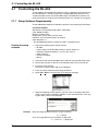
3.1.1 Setup Software Requirements
The BL-500 Setup Software for Windows operates in the following environments:
Personal Computer
IBM PC/AT or compatible model (100% compatible)
CPU: 80386 or higher
Memory: 4 MB or more
Floppy drive: One or more 3.5 inch drives
RS-232C: One serial port (COM 1 or COM 2)
DOS: Windows 3.1
* The BL-500 Setup Software applies to COM 1 and COM 2 only.
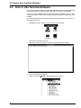
Starting the setup
software
1. Prepare the following items before starting.
• BL-500
• Power supply unit for BL-500 (5 VDC) or the BL-U1/BL-U2
• RS-232C cable described on p. 2 to 4 in this manual
• Setup software
• Personal computer
• Mouse
2. Connect the PC with the BL-500 or BL-U1/BL-U2 using the RS-232C cable.
3. Set the DIP switches on the BL-U1 to RS-232C when you use the BL-U1.
4. Install the setup software.
Turn the PC’s power switch ON to start Windows.
5. Insert the setup software into the floppy disk drive.
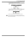
6. Select File - Run on the menu bar of the program manager.
7. When the following screen appears, type the name of the floppy disk drive
and the name of the installed file “SETUP” in the “Command Line”. After typing the above, click on the OK button.
Example
When the floppy disk drive name is A, type as follows:
A:\SETUP
Then, the target directory for installation is displayed.
“C:\BL500” is displayed.
24
3.1 Controlling the BL-500
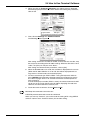
8. To accept the directory name, click on the OK button.
To change the directory name, click on the column displaying the directory
name, type a desired directory name using the keyboard, and click on the OK
button.
9. After the installation is completed, the “KEYENCE Barcode Reader” window
is created in the program manager. In this window, icon “BL50WIN” is created.
10. To start the setup software, double-click on the “BL50WIN” icon.
11. After the setup software gets started, the following screen appears:
Note
When using a monochrome display on a laptop PC, the display appears in reverse video. To make the display clearer, set the laptop’s display to reverse video
and then restart the setup software.
25
3.2 Operating Procedure
3.2 Operating Procedure
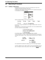
3.2.1 Outline of Operation
To operate the setup software, place the mouse pointer on the item to be
changed, and click the left button of the mouse.
Use the Down Arrow button to select an item from a list. Place the mouse pointer
on a desired item, and click on the item.
Click on the Option button to select one of several items.
In the above settings, Read mode is set to “Single” and Data-send is set for “At
trigger input.”
The Check Box is used to enable special functions. An “X” in the Check Box indicates that a function has been enabled.
In the above settings, “Inspect check-digit[Modulus43]” is enabled.
To enter characters or a value in a field, insert the mouse pointer over the field.
The pointer will change to a cursor. Click inside the field and type in the desired
value.
If the specified value exceeds the setting range, an error message will appear
To shift to a different screen, click the mouse cursor one of the buttons in the window. For example to return to the previous screen, click on the
button.
26
3.3 Setup Software Operating Procedure
3.3 Setup Software Operating Procedure
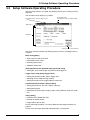
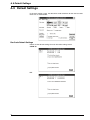
After the setup software is started, the following screen (main setting screen) is
displayed.
The function of each display is as follows.
Title (Name of the current setting screen)
Current file name
The initial file name is “Untitled. CFG”.
Menu bar (*)
Parameter
Setting screen selector buttons
The setup software provides the following setting screens according to the parameters.
Main setting [Main]
• Type of the bar code to be read
• Read mode and its setup
• Decoding match count
• Additional information
Setting details for the specified code type [Code setup]
• Setting No. of bar code length, inspection of check-digit, etc.
Trigger input setup [Setup Trigger input]
• Setting the operation mode and the trigger input
• Selecting the test mode starting method
• Setting characters for the trigger ON/OFF command
Communication parameters [Setup comm]
• Setting the baud rate, data bits, stop bit and parity
• Setting the protocol
• Setting the Communication strings (header string, delimiter, read error code,
etc.)
Utility [Utility]
• Indication of the STABILITY LED
• Duration of OK/NG output
• Registration of preset data
For the operating procedure, see “Setup Software Operating Procedure” on
page 27.
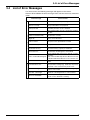
For the error messages displayed during operation, see page 39.
27
3.3 Setup Software Operating Procedure
Menu Bar
The following operations can be performed using the menu bar.
File Menu (Alt+F)
Specifies a file name/Saves a file.
Exits the setup software.
Send Settings (Alt+S)
Sends settings to the BL-500.
Info (Alt+I)
Indicates the version number of this software.
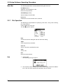
3.3.1 File Operation
The following is the procedure for specifying a file name, saving a file or exiting
the setup software.
Click on File in the menu bar.
The following menu appears.
New
Cancels the current setting file and calls the initial setting.
Open
Calls the previously stored file.
Save As
Saves a file with a specified file name.
Save
Saves a file.
Exit
Exits the setup software.
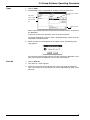
New
1. Click on New.
The following message appears.
2. To cancel the current settings and call the initial setting, click on the OK button. If you wish not to execute this operation, click on Cancel
.
28
3.3 Setup Software Operating Procedure
Open
1. Click on Open.
2. The following screen is displayed for selection of the file to be read.
Directory selection
list
File name
entry column
File selection
list
Drive selection
list
Select a desired file from those listed in the file selection column, and click on
the OK button.
If you wish to cancel this operation, click on the Cancel button.
To change the directory or drive, select a desired directory or drive in the directory/drive selection column.
3. When you click on the OK button on the above screen, the following message appears.
To cancel the current setting and call a new file, click on the OK button. If you
wish not to execute this operation, click on the Cancel button.
Save As
1. Click on Save As.
2. The “Save As” screen appears.
3. Click in the file name entry field and type a file name using the keyboard.
Type a file name of up to 8 characters. Be sure to add extension “CFG” to the
file name.
29
3.3 Setup Software Operating Procedure
Example
When the file name is “TEST”:
1. Click on the file name entry column.
2. Enter “TEST. CFG” as the file name.
3. Click on the OK button.
If you wish cancel this operation, click on the Cancel button.
To change the directory or drive, select a desired directory or drive in the
directory/drive selection column.
4. If the specified file name has already been stored, the following message will
appear.
To save the setting by overwriting the existing file, click on the OK button. If
you wish not to save the setting, click on the Cancel button.
Save
A file name must be entered before the file can be saved
1. Click on Save. The file will be saved.
Exit
1. Click on Exit.
The following message appears.
2. To exit the setup software, click on the OK button. If you wish cancel, click on
Cancel.
Save the current settings before exiting the setup software.
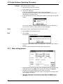
3.3.2 Main setting screen
1. Place the mouse cursor at the item to be changed and click it, or move to the
target item by pressing [TAB]. Then, change the setting using [Space].
2. To codes 1 to 4, specify the types of bar codes to be read.
If you specify 4 different types of bar codes, the BL-500 can read them without changing the settings.
3. To set the code length or the inspect for check-digit, click Setup or press
[ENTER] to move to the setup screen for each code (see page 31 to 34).
30
3.3 Setup Software Operating Procedure
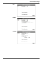
4. When selecting Single for Read mode, the following appears on the screen:
When selecting Multi 1 or Multi 2, the following appears on the screen:
Set the time within the range from 1 to 255 (100 ms to 25.5 s).
When selecting Multi 3, none of the above information appears.
5. In the Additional information field, you can select one or more items. However, the scan count is given only when the decode count is selected.
Note
Read mode --> Page 10
Data-send --> Page 9
Repeating-reading time --> Page 10
Decoding match count --> Page 8
Additional information --> Page 20
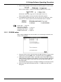
3.3.3 CODE39 setup
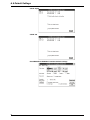
When setting CODE39 to any one of codes 1 to 4 and trying to set details, this
setting screen appears.
1. Place the mouse cursor at the item to be changed and click it, or move to the
target item by pressing [TAB]. Then, change the setting using [Space].
2. Setting Max code length and Min. code length allows the BL-500 to read bar
codes having the specified range of digits. If you want to read bar codes with
the specific code length, set the same value to both Max code length and
Min code length.
The allowable setting range is 3 to 32 digits including the start/stop character.
3. When you select Send start/stop character, * is added to the data when
being sent.
31
3.3 Setup Software Operating Procedure
4. When you select Inspect check-digit, the following information appears:
The above setting sends the data together with the check-digit.
Modulus 43 is used to calculate the check-digit.
5. When you select Max code length output, the following information appears:
Set Effective and Starting from 1 to 32.
6. When you select Specify label orientation, the following information appears:
7. Click the Return button or press [ENTER] to return to the main setting
screen.
Note
Max. code length output --> Page 22
Specify label orientation --> Page 14
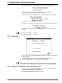
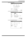
3.3.4 ITF setup
1. Setup is the same as the CODE39 setup. However, ITF does not have Start/
stop character.
2. Set code length using a even value within the range from 2 to 32.
3. Modulus 10/Weight3 is used to calculate the check-digit.
Note
When reading the standard distribution code (bar code on the corrugated fiberboard box), set the code length to 14 or 16 and select the Inspect check-digit.
3.3.5 Setup for Industrial 2 of 5 and COOP 2 of 5
1. Setup is the same as the CODE39 setup. However, a start/stop character
and Inspect check-digit are not provided.
2. Set code length within the range from 1 to 32.
32
3.3 Setup Software Operating Procedure
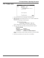
3.3.6 Codabar setup
1. Set code length from 3 to 32 including the start/stop character.
2. When you select Send start/stop character, A, B, C, and D are added to the
data to be sent.
In this case, the following information appears:
You can select lowercase or uppercase for the start/stop character.
3. When you select Inspect check-digit, the following information appears:
Specify the check-digit calculation method and whether or not the check-digit
is sent.
4. Set the other parameters in the same manner as for CODE39.
33
3.3 Setup Software Operating Procedure
3.3.7 UPC/EAN setup
1. Select Read EAN 8 code, Read UPC-A[EAN13] code or Read UPC-E to
enable to read.
If you select Read UPC-A[EAN13] code, the following information appears,
asking you to select which digits you want to output on UPC-A.
If you select Read UPC-E, the following information appears, asking if you
want to send data with the leading zero-suppressed.
2. You can use the same setting procedure as for CODE39 for Max code length
output and Specify label orientation. However, the setting range of Effective
and Starting in Max code length output is limited to the code length of the
readout UPC/E code.
• Although the check-digit parameter is not provided on the screen, the system
internally calculates it using modulus 10/Weight3. (The calculated data is
sent.)
3.3.8 CODE128 setup
1. The setting range of code length depends on the start character type CODEA to C (see page 72).
• CODE-A and B --- 1 to 32
• CODE-C --- 2 to 64
The code length does not include the start/stop character or check-digit. Also,
FNC1 to 4 (function codes), SHIFT, and CODE-A to C are excluded from the
code length.
34
3.3 Setup Software Operating Procedure
2. Check that the double-character start pattern is regulated in the UPC/EAN128 standard. It means the combination of start character (CODE-C) and
FNC1 (function code 1). The standard specifies that the UPC/EAN-128 bar
codes should start with the double character start pattern.
Using this parameter, you can specify that reading will not start without the
double character start pattern.
3. You can use the same setting procedure as for CODE39 for Max code length
output and Direction. However, the setting range of Effective and Starting in
Max code length output is 1 to 64 if the start character is CODE-C.
• Although the check-digit parameter is not shown on the screen, the system
internally calculates it using modulus 10/Weight3. (The calculated data is not
sent.)
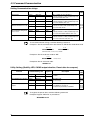
3.3.9 Trigger input setting
1. Place the mouse cursor at the item to be changed and click it, or move to the
target item by pressing [TAB]. Then, change the setting using [Space].
2. Select Level synchronization or One-shot synchronization as the scanning
method. When you select One-shot, the following information appears, asking you to set the scanning time:
Set the scanning time within the range from 1 to 255 (100 ms to 25.5 s).
3. When you select “Test mode initiated with trigger input ON” or “Test mode initiated at startup,” the following information appears, asking you which test
mode you want to start:
If you select both “Test mode initiated with trigger input ON” and “Test mode
initiated upon power-up,” “Test mode initiated with trigger input ON” is used.
4. In the Command for trigger input parameter, you can freely change the characters for the Trigger ON/OFF command (within 8 characters).
Normally, you should use the default setting (Lon, LOff).
5. Click the Return button or press [ENTER] to return to the main setting
screen.
Note
Scanning method --> Page 8
Starting the test mode --> Page 15
Trigger ON/OFF command --> Page 49
35
3.3 Setup Software Operating Procedure
3.3.10 Communication setting
1. Place the mouse cursor at the item to be changed and click it, or move to the
target item by pressing [TAB]. Then, change the setting using [Space].
2. When setting the header string, delimeter, and read error, click [Communication strings] or press [ENTER] to move to the communication strings setting
screen.
3. Click the Return button or press [ENTER] to return to the main setting
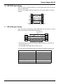
screen.
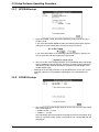
If you use multidrop link, click on “Set RS-485 multidrop link”. When you click this
box, “ID No: [ ]” message will appear. Then specify the proper ID number for the
BL connected. After that, transmit the setting to the BL. Then repeat the same procedure for the other BLs. Please change the ID number so that the ID numbers
differ among all BL readers connected.
Note
(Communication) protocol --> Page 45
The setup software does not allow you to set the baud rate to 19200 to 38400 bit/
s. If you want to set the baud rate within this range, use the serial commands (see
page 57).
3.3.11 Communication strings setup
1. Place the mouse cursor at the item to be changed and click it, or move to the
target item by pressing [TAB]. Then, change the setting using [Space].
2. Select appropriate values for Header string and Delimiter from among the
displayed items. When you select Custom, the following appears:
Then, you can enter the desired value from the keyboard (within 5 characters).
36
3.3 Setup Software Operating Procedure
3. When you select Default[:] for Partition mark and Intermediate delimiter,
these parameters are set as below:
When you select Custom, the following appears:
Then, you can enter the desired value from the keyboard (using one character
for the partition mark and 5 characters or less for the intermediate delimiter).
4. Input the Read error using the keyboard.
You can change the code as desired (within 8 characters).
Normally, you should use the default setting (ERROR). You can chose not to
send the read error by selecting a null value for the read error.
5. Click the Return button or press [ENTER] to return to the communication
setting screen.
Note
Header string, delimeter --> Page 46
Partition mark --> Page 20
Intermediate delimiter --> Page 11
Read error --> Page 46
3.3.12 Other setting
1. Place the mouse cursor at the item to be changed and click it, or move to the
target item by pressing [TAB]. Then, change the setting using [Space].
2. By setting STABILITY LED, STABILITY LED turns on which indicates reading
stability during the normal reading operation.
3. To set OK/NG output duration, enter the appropriate numeric value from the
keyboard. The setting range is from 1 to 255 (10 ms to 2.55 s).
4. To set Compare with, enter the preset data to be registered from the keyboard.
Usually, specify the data within 32 characters. If you are using CODE128 and
the start character is CODE-C, you can set the data using up to 64 characters.
5. Click the Return button or press [ENTER] to return to the main setting
screen.
Note
STABILITY LED --> Page 17
OK/NG output duration --> Page 8
Preset data --> Page 19
37
3.3 Setup Software Operating Procedure
3.3.13 Sending Settings
1. Choose Send from the menu bar. The following screen appears.
2. Set the baud rate, data bits, stop bit and parity according the BL-500’s settings. The BL-500’s default settings are shown above.
3. Specify whether the parameter settings are to be saved in the EEPROM or
not. If the current settings are not saved in the EEPROM, the setup software
will start with the previous settings when the power is turned on again.
4. After setting the communication parameters, click on OK. Data transmission
will begin. If a communication error occurs, the following message will
appear.
If you are not sure of the communication parameter settings of the BL-500,
turn ON the BL-500’s power switch before executing data transmission, and
set the communication parameters as shown in step 1.
* The BL-500’s communication parameters are set as shown above for 5 seconds after the power is turned ON. (see page 44.)
5. If the setup software is normally exited, it will return to the main setting
screen.
3.3.14 Version Display
1. Click on Info on the menu bar.
2. The following screen appears, where you can confirm the version of this
setup software.
38
3.4 List of Error Messages
3.4 List of Error Messages
If an error occurs, the following messages will appear on the screen.
Click on OK and delete the error message. Then, take the necessary corrective
action.
Error message
File not found.
The file specified for Open Setting does not exist.
Drive is not ready.
The specified disk is not prepared.
Write protected.
Overwrite protection is set to the disk.
Illegal filename (must be in
format of xxxxxxxx.CFG.)
The remaining disk capacity is insufficient. Replace
the disk.
The file name does not have extension CFG. Enter
the file name correctly.
Illegal file.
Use a correct file name.
Path not found.
The pass for the specified file is invalid.
Device not ready.
The specified drive is invalid.
Insufficient memory.
The main memory capacity is insufficient.
Device I/O error
The disk may be damaged or unformatted.
Error during file operation
Insufficient disk space.
Error during setup
Cause of error
The stored file data are incorrect. Specify a correct
file name.
This is not BL-500 setting file.
Data of the BL-500 setup file are different from that
of the BL-180. These files are not for common use.
The stored file data are damaged. Specify a new file
Error in detailed code data.
name.
An error occurred during communication.
The parameter settings (e.g. baud rate) may not be
Communication error
matched, or the connection may be incorrect.
The specified value is exceeding the setting range.
Value out of range.
Enter a correct value.
Min. code length is set larger The minimum code length is set larger than the
than Max. code length.
maximum code length. Enter a correct number.
The serial port is being used for a device other than
Device is unavailable.
the BL or else “Terminal” is running.
39
3.5 How to Use Terminal Software
3.5 How to Use Terminal Software
The terminal software allows bar code data to be displayed on a Windows-based
personal computer and allows serial commands to be sent to the BL-500.
You can use the standard terminal software included in Windows Ver. 3.1. This
section describes how to use the terminal software to confirm the operation of the
BL-500.
For more information on the terminal software and its functions, please refer to
the Windows manual.
1. Double-click on the Terminal icon in the Accessory Group.
The terminal software starts up.
2. When the terminal software is started, the following screen appears.
3. First, set the terminal software.
When you click on Settings, the following menu appears.
40
3.5 How to Use Terminal Software
4. When you click on Terminal Preferences, the setting screen is displayed.
Set the displayed parameters as shown below. After setting the parameters,
click on OK.
5. Then, Click on Settings then Communications.
The following screen appears.
After setting “Connector” to COM1 or COM2, set the baud rate, data bits, stop
bits and parity according to the BL-500’s settings. When the data bits is set to
“8 bits”, the parity can only be set to “None.”
After setting the communication parameters, click on [OK].
6. When the BL-500 reads a bar code, the read data is displayed on the screen.
(When the BL-500’s delimiter is set to CR, data will be displayed with carriage returns. Control codes cannot be displayed.)
7. To send a command, type TEST 1/TEST 2 using the keyboard, and then
press [ENTER]. All commands should be entered in all uppercase characters. Refer to pages 49 to 51 for available commands and descriptions of
each command.
In read rate display test mode (TEST 1 mode), the entered command is difficult to see on the screen because the BL-500 is displaying the read data.
However, the command will be correctly sent.
8. To exit the terminal software, click on File then Exit.
Note
Multi drop link commands cannot be sent.
RTS/CTS protocol commands cannot be confirmed.
When you start up “Terminal”, you cannot send the setting to BL using SETUP
software. Quit on close “Terminal” before you send the setting.
41
3.5 How to Use Terminal Software
42
Chapter 4
Serial Communication (RS-232C/RS-422A)
4.1 Serial Communication
4.1 Serial Communication
The BL-500 communicates with the PC via the RS-232C serial port. This enables
you to change the BL-500’s settings from your PC.
Communication Types
The BL-500 provides the following two communication types:
Data communication
Sends read bar code data from the BL-500 to the PC.
Command communication
Changes the BL-500’s settings by sending a command from the PC to the BL500.
All communication is performed using ASCII codes.
4.1.1 Communication Setup
Configure the setup for BL-500 and the PC before attempting serial communication.
Setup of BL-500
Set the following parameters for the BL-500 using the setup software.
Baud rate, Data bits, Parity, Stop bit, Communication protocol, Header/Delimiter,
Read error code
PC setup
Based on the BL-500’s settings, set the communication parameters on the PC using the “Ports” setting in the Windows Control Panel.
Note
The following communication parameters are the default settings for the BL-500:
Baud rate:
Data bits:
Parity:
Stop bit:
9600 bps
7 bits
Even
1 bit
Set the PC according to the above settings before attempting communication.
The BL-500 is set, temporarily, to the default settings for 5 seconds after the power switch is turned on.
When the current settings of BL-500 is not certain, send the command “SSET”
and a [CR] to the BL-500 from your PC with 5 seconds after power-up. This causes the BL-500 to remain at its default settings and you can communicate with the
BL-500 at the default settings.
For information on checking the BL-500’s current settings, see “Details on Parameter Setting Commands” on page 50. For information on changing the above
communication parameters see “Description of Parameter Setting Commands”
on page 52.
Note
44
All commands should be entered in all uppercase characters. The BL cannot accept lowercase characters.
4.2 Details on Data Communication
4.2 Details on Data Communication
4.2.1 Communication Protocols (Hardware handshaking)
The BL-500 supports the following four handshaking protocols.
No Handshaking
The BL-500 sends read data to the PC without using any handshaking protocol.
Read data
PASS/RTRY Handshaking
After sending the read data, the BL-500 waits for a response from the PC. The
response is either a PASS command or a RTRY command.
Read data
Response
(PASS
C
R
, RTRY
C
R
)
The PASS command (quit) indicates that the PC has successfully received one
data packet. The BL-500 then prepares for the next data transmission.
The RTRY command (request to re-send) indicates that the data was not transmitted successfully. The command is a request to the BL-500 to re-send the data.
The BL-500 sends the same data again and then waits for the response.
After the BL-500 once receives PASS, the BL-500 sends back no data even if
RTRY is sent to the BL-500.
The BL-500 can continue to read while waiting for the PASS command. The data
is stored in the BL-500’s transmission buffer (For the capacity of the transmission
buffer, see page 46).
If the amount of stored data exceeds the capacity of the transmission buffer, the
BL-500 sends back <Header>OVER<Delimiter> to the PC, and clears all data
stored in the transmission buffer. For more information, see “Capacity of Transmission Buffer” on page 46.
Note
The BL-500 can receives other commands while waiting for the PASS command.
In this case, the BL-500 sends back an immediate response (e.g. OK).
When the SSET command (see “4.3.3” on page 50) is sent to the BL-500 while
the BL-500 is waiting for the PASS command, the BL-500 clears the data stored
in the transmission buffer, and enters the setting mode.
ACK/NAK Handshaking
The ACK/NAK handshaking uses ACK (06H) and NAK (15H) instead of PASS
and RTRY used in the PASS/RTRY handshaking, respectively. With these protocols, the BL-500 sends back different characters, but performs the same operation.
45
4.2 Details on Data Communication
RTS/CTS Handshaking
When the PC’s RTS (BL-500’s CTS) signal turns off, the BL-500 becomes ready
for data transmission. When the PC’s RTS signal turns on, the BL-500 starts data
transmission.
When the PC’s RTS signal is off, the BL-500 can still read. In this case, data is
stored in the BL-500’s transmission buffer (see 4.2.2 below).
If the amount of stored data exceeds the capacity of the transmission buffer, the
BL-500 sends back <Header>OVER<Delimiter> to the PC, and clears all data
stored in the transmission buffer.
Note
The RTS/CTS handshaking cannot be used for RS-422A communication.
The RTS/CTS protocol can be used together with other handshaking protocols.
When the PC’s RTS signal is off, the BL-500 does not sends back a response to
the PC.
4.2.2 Capacity of Transmission Buffer
The BL-500’ s transmission buffer can store 400 bytes (400 characters).
The number of characters stored in the transmission buffer for each data packet
is the number of characters in the data (including additional data such as the number of decoding match count) plus an additional five characters indicating the data’s attributes.
When multi label reading mode 2 or 3 is used, these five attribute characters are
added to each data packet.
Example 1
When the number of bar code digits is 10 (with no additional data)
400 ÷ (10 + 5) = 26
The transmission buffer can store 26 pieces of data.
Example 2
When the number of bar code digits is 20 (with no additional data)
400 ÷ (20 + 5) = 16
The transmission buffer can store 16 pieces of data.
4.2.3 Read Data Format
Set the data format of the Header and Delimiter, respectively.
Header
Read data
Delimiter
With the setup software, the following formats can be selected. Other than the following formats, you can freely set up to 5 characters.
Header
ESC (1BH)/STX (02H)/None
Delimiter
CR (ODH)/CR (ODH) LF (OAH)/ETX (O3H)
46
4.2 Details on Data Communication
4.2.4 Read Error Code
If the BL-500 fails to read a bar code, the B-500 sends back a read error code.
The initial setting of the read error code is as follows:
Header
ERROR
Delimiter
The read error code can freely be changed (within 8 characters).
The BL-500 can be set to send no error code (see page 36).
47
4.3 Command Communication
4.3 Command Communication
The BL-500 includes commands to directly operate the BL-500 (direct control
commands) and the commands used to change or confirm the BL-500’s settings
(parameter setting commands).
4.3.1 Setup of Direct Control Commands
Communication procedure
Command
Response
1. Send a direct control command from the PC to the BL-500.
2. After receiving the command, the BL-500 sends back an OK response and
executes the required operation.
When the read operation control command or test mode control command is
sent to the BL-500, the BL-500 sends back no response.
3. When an incorrect command is sent to the BL-500, the BL-500 sends back
no response.
Note
LF can be added after the command being sent. In this case, however, LF is not
added to the response data.
When ESC is inserted before the command being sent, characters in the BL500’s command receiving buffer are cleared.
If the BL-500’s command receiving buffer contains erroneous characters due to
data transmission error during communication, add ESC to the command being
sent.
Note
48
For command communication, set the time duration between transmission of
each character (byte) to up to 30 seconds. If this duration exceeds 30 seconds,
the BL-500 cancels the received characters.
4.3 Command Communication
4.3.2 Explanation of Direct Control Commands
The following describe direct control commands in details.
Read operation control
This command specifies the data read timing.
[LON]
Trigger on
Command: LON
Response: None
[LOFF]
Trigger off
Command: LOFF
Response: None
• Even when the read operation is controlled with these commands, the BL-500
performs the same operation as with the trigger input (see page 8 to 10).
• “Trigger input: on” corresponds to LON, and “trigger input: off” corresponds to
LOFF.
• The BL-500 starts read operation on receipt of LON and stops it on receipt of
LOFF.
• When a bar code can be correctly read and the read data has already been
set, you need not send LOFF.
• The command characters can be freely changed (within 8 characters).
Test mode control
Starts or quits the test mode.
[TEST1]
Reading rate check
Command: TEST1
Response: None
[TEST2]
Tact check
Command: TEST2
Response: None
[QUIT]
Resetting test
Command: QUIT
Response: None
• After using the test mode, be sure to reset it.
OK/NG output control
Directly turns on/off the OK/NG output.
This enables you to easily check wiring.
[OKON]
Turning the OK output on
Command: OKON
Response: OK
[NGON]
Turning the NG output on
Command: NGON
Response: OK
[ALLOFF]
Turning the OK/NG outputs off
Command: ALLOFF
Response: OK
49
4.3 Command Communication
Clearing transmission buffer
[BCLR]
Clears data stored in the transmission buffer.
Command: BCLR
Response: OK
Shift to setting mode
[SSET]
Enters the setting mode (see page 49).
Command: SSET
Response: OK
Laser off/Resetting Laser off
Turns off the laser emission when the laser beam may cause injury to an operator
(see page x).
[LOCK]
Laser off
Command: LOCK
Response: OK
[UNLOCK]
Resetting Laser off
Command: UNLOCK
Response: OK
• When the Laser off command is executed, bar code read operation (laser
emission) is disabled until the Laser off command is reset by using UNLOCK
command.
• The Laser off command is retained even after the power is turned off.
4.3.3 Details on Parameter Setting Commands
The following describes how to change the BL-500’s settings through command
communication.
You can use the setup software to change the BL-500’s settings instead of these
commands.
Communication Details
1. Send the direct control command SSET to the BL-500.
The BL-500 will shift to setting mode.
After successfully executing the command, the BL-500 sends back an OK.
2. After the BL-500 shifts to setting mode, send the command (setting change
command) corresponding to the item to be changed to the BL-500.
After successfully executing the command, the BL-500 sends back an OK.
If an error occurs with this command, the BL-500 sends back ERRnn. (nn
stands for error code numbers.)
3. To confirm the current settings, send a setting confirmation command.
After successfully executing the command, the BL-500 sends back an OK.
If an error occurs with this command, the BL-500 sends back ERRnn.
4. To save the current settings in the EEP-ROM, send SAVE to the BL-500.
Once you save the settings in the EEP-ROM, the BL-500 will start with these
settings when the BL-500 is turned on next.
After successfully executing the command, the BL-500 sends back an OK.
If an error occurs with this command, the BL-500 sends back ERRnn.
5. To quit the setting mode and perform the normal bar code reading, send
SEND to the BL-500.
After successfully executing the command, the BL-500 sends back an OK.
If an error occurs with this command, the BL-500 sends back ERRnn.
50
4.3 Command Communication
Note
[LF] can be added at the end of the command being sent. In this case, however,
[LF] is not added to the response data.
When [ESC] is added before the command being sent, characters in the BL-500’s
command receiving buffer are cleared.
If the BL-500’s command receiving buffer contains erroneous characters due to a
data transmission error during communication, add [ESC] to the command being
sent.
Note
For command communication, set the time duration between transmission of
each character (byte) to up to 30 seconds. If this duration exceeds 30 seconds,
the BL-500 cancels the received characters.
51
4.3 Command Communication
4.3.4 Response Error Code
When an incorrect command is sent to set parameters, the BL-500 sends back
data indicating the cause of the error (error code). For the commands corresponding to the error codes, see the error code column given in the table on the following pages.
Error code
Cause of error
00
01
02
03
Undefined command.
Command format is incorrect.
Nothing corresponds to the number in the command.
“m” value (codes 1 to 4) is other than 0 to 3.
“Bar code type setting command” was not sent first.
Sending “No. of readable digits setting command” is invalid
for UPC/EAN code.
The number in the command is too long.
“hhh...” data is too short.
“n” value is not 0 or 1.
“n” value is exceeding the setting range.
“nnn” or “nn” value is exceeding the setting range.
“hhh...” is not specified in HEX (hexadecimal) code.
“hhh...=FF” cannot be set.
“hhh...” or “aaa...” contains more than the specified number
of characters.
Characters of “aaa...” are invalid.
Data in the EEPROM may be damaged. Perform initial
setup.
Error in the area storing initial settings.
Settings are automatically initialized.
\ is not followed by !, ? or \ in preset data. (See page 72.)
Two !s exist in preset data. (See page 19.)
The BL-500 may malfunction. Contact KEYENCE.
04
05
06
07
08
09
10
11
12
13
14
15
17
18
99
4.3.5 Description of Parameter Setting Commands
Saving/Initializing Settings/Quitting Setting Mode
Function
Response
Saves settings in the EEPROM.
Initializes settings.
SAVE
OK
See page 49.
DFLT
OK
Quits the setting mode.
SEND
OK
Returns to the default-settings, and saves the set- 00,05
tings in the EEP-ROM.
14,15
See page 49.
-
52
Description
Error
Code
Command being sent
-
4.3 Command Communication
Setting Bar Code Type and Number of Readable Digits for Codes 1 to 4
The following describes the parameter setting commands for Codes 1 to 4.
Be sure to send “Bar code type setting command” first before setting other parameters.
Note
When “Bar code type setting command” is newly sent, all other parameters for the
specified code will return to the default settings.
In this case, set all other parameters again.
Setting change commands and setting confirmation commands are described on
the following pages.
Function
Setting bar code type for
codes 1 to 4.
Setting Max. No. of readable
digits
command being sent
Change
Confirm
CODEm=n
CODEm
Response
OK
mn
Setting Min. No. of readable
digits
Change
Confirm
Change
Confirm
MAXm=nn
MAXm
MINm=nn
MINm
OK
mnn
OK
mnn
CODE39
Sending start/stop character.
Change
Confirm
WCm00n
RCm00
OK
00n
CODE39
Inspection of check digit
(Modulus 43)
Change
Confirm
WCm01n
RCm01
OK
01n
Function
Command being sent
Response
Description
m= 0 to 3:Codes 1 to 4
n= 0:CODE 39
1:ITF
2:Industrial2-of-5
3: Codabar
4: UPC/EAN
5: CODE128
6: COOP2-of-5
7: None
m= 0 to 3: Codes 1 to 4
nn= 01 to 32
* For CODE39, Codabar: 03 to 32
* For ITF: 02 to 32
* For CODE128: 01 to 64
Note:
With EAN code, this command causes error.
m= 0 to 3: Codes 1 to 4
n= 0: Disable
1: Enable
m= 0 to 3: Codes 1 to 4
n= 0: Disable
1: Enable
Description
CODE39
Sending check digit.
Change
Confirm
WCm02n
RCm02
OK
02n
m= 0 to 3: Codes 1 to 4
n= 0: Disable
1: Enable
ITF
Inspection of check digit
(Modulus 10)
Change
Confirm
WCm10n
WCm10
OK
10n
m= 0 to 3: Codes 1 to 4
n= 0: Disable
1: Enable
ITF
Sending check digit.
Change
Confirm
WCm11n
RCm11
OK
11n
Codabar
Sending start/stop character.
Change
Confirm
WCm30n
RCm30
OK
30n
Codabar
Start/Stop character type
Change
Confirm
WCm31n
RCm31
OK
31n
Codabar
Inspection of check digit
Change
Confirm
WCm32n
RCm32
OK
32n
Codabar
Sending check digit
Change
Confirm
WCm33n
RCm33
OK
33n
m= 0 to 3: Codes 1 to 4
n= 0: Disable
1: Enable
m= 0 to 3: Codes 1 to 4
n= 0: Disable
1: Enable
m= 0 to 3: Codes 1 to 4
n= 0: Lower case
1: Upper case
m= 0 to 3: Codes 1 to 4
n= 0: Disable
1: Enable
m= 0 to 3: Codes 1 to 4
n= 0: Disable
1: Enable
Error
Code
00, 01
03, 05
08, 14
00, 01
03, 04
05, 09
14
00, 02
03, 04
05, 07
14
Error
Code
00, 02
03, 04
05, 07
14
53
4.3 Command Communication
Function
Command being sent
Response
Codabar
Setting check digit type
Change
Confirm
WCm34n
RCm34
OK
34n
UPC(A-E)/EAN
Change
Confirm
WCm40n
RCm40
OK
40n
Change
Confirm
WCm41n
RCm41
OK
41n
Reading UPC-E
UPC(A-E)/EAN
Reading EAN 8 digits
Function
UPC(A-E)/EAN
Reading JAN 13 digits
UPC(A-E)/EAN
No. of UPC-A output digits
UPC(A-E)/EAN
Adding “0” to UPC-E system
code
Command being sent
Response
Change
Confirm
WCm42n
WCm42
OK
42n
Change
Confirm
WCm43n
RCm43
OK
43n
Change
Confirm
WCm44n
RCm44
OK
44n
CODE128
Checking double character
start pattern
(See p. 34.)
Setting max. code length output function
Change
Confirm
WCm51n
RCm51
OK
51n
Change
Confirm
WCm83n
RCm83
OK
83n
Setting direction for max.
code length output
Change
Confirm
WCm84n
RCm84
OK
84n
Setting effective digits for
max. code length output
Change
Confirm
Change
Confirm
WCm85nn
RCm85
WCm86nn
RCm86
OK
85nn
OK
86nn
Setting label orientation speci- Change
fied reading
Confirm
WCm81n
RCm81
OK
81n
Setting orientation for orienta- Change
tion- specified reading
Confirm
WCm82n
RCm82
OK
82n
Setting starting digit for max.
code length output
54
Description
m= 0 to 3: Codes 1 to 4
n= 0: Mudulus16
1: Modulus 11
2: Modulus 10/Wait 2
3: Modulus 10/Wait 3
4: 7 Check DR
5: Modulus 11-A
6: Modulus 10/Wait 2-A
m= 0 to 3: Codes 1 to 4
n= 0: Disable
1: Enable
m= 0 to 3: Codes 1 to 4
n= 0: Disable
1: Enable
Description
Error
Code
00, 02
03, 04
05, 08
14
00, 02
03, 04
05, 07
14
Error
Code
m= 0 to 3: Codes 1 to 4
n= 0: Disable
1: Enable
m= 0 to 3: Codes 1 to 4
n= 0:Output in 13 digits
1:Output in 12 digits
m= 0 to 3: Codes 1 to 4
n= 0: Disable
1: Enable
m= 0 to 3: Codes 1 to 4
n= 0: Disable
1: Enable
00, 02
03, 04
05, 07
14
m= 0 to 3: Codes 1 to 4
n= 0: Disable
1: Enable
m= 0 to 3: Codes 1 to 4
n= 0: Forward
1: Reverse
m= 0 to 3: Codes 1 to 4
nn= 01 to 32: Effective digits
m= 0 to 3: Codes 1 to 4
nn= 01 to 32:
Starting digit
m= 0 to 3: Codes 1 to 4
n= 0: Disable
1: Enable
m= 0 to 3: Codes 1 to 4
n= 0: Forward
1: Reverse
00, 02
03, 04
05, 09
14
00, 02
03, 04
05, 07
14
4.3 Command Communication
Setting Reading Mode/Data Addition Functions
Function
Command being sent
Response
Setting reading mode
Change
Confirm
WP12n
RP12
OK
12n
Setting data send timing
Change
Confirm
WP13n
RP13
Setting repeat-read time in
Change
multi label reading mode 1 or Confirm
2
Setting decoding match count Change
Confirm
Setting decoding match count Change
in additional information
Confirm
Setting scans in additional
Change
information
Confirm
Setting label orientation in
additional information
Change
Confirm
Setting code type in additional Change
information
Confirm
Description
Error
Code
n= 0: Single label
1: Multi label 1
2: Multi label 2
3: Multi label 3
00, 02
05, 08
14
OK
13n
N= 0: Sends data after reading
1: Sends after timing input turns off
00, 02
05, 07
14
WP41nnn
RP41
OK
41nnn
nnn=001 to 225
(by 100 ms step)
WP43nnn
RP43
WP10n
RP10
WP11n
RP11
OK
43nnn
OK
10n
OK
11n
WP14n
RP14
WP17n
RP17
OK
14n
OK
17n
nnn=001 to 225
00, 02
05, 09
14
n= 0: No addition
1: Add
n= 0: No addition
1: Add
Note:
Effective only when No. of decodings are added.
n= 0: No addition
1: Add
00, 02
05, 07
14
n= 0: No addition
1: Add
55
4.3 Command Communication
Setting Trigger Input (Starting Test Mode)
Function
Command being sent
Setting signal type
Setting one-shot input time
Setting time constant of trigger input
Setting state of trigger input
Starting test mode when trigger input turns on.
(To specify the test mode, use
the command below.)
Specifying the test mode to be
started when trigger input
turns on.
Starting test mode when
power is turned on.
Setting characters of trigger
on command
Setting characters of trigger
off command
Note
Description
Response
Change
Confirm
Change
Confirm
Change
Confirm
Change
Confirm
Change
Confirm
WP05n
RP05
WP42nnn
RP42
WP04n
RP04
WP03n
RP03
WP06n
RP06
OK
05n
OK
42nnn
OK
04n
OK
03n
OK
06n
Change
Confirm
TRGTn
TRGT
OK
TRGTn
N= 1: Reading rate check mode
2: Tact check mode
Change
Confirm
TESTn
TEST
OK
TESTn
n= 0: Reset
1: Reading rate check mode
2: Tact check mode
Change
Confirm
Change
Confirm
WP56hhh...
RP56
WP57hhh...
RP57
OK
56hhh...
OK
57hhh...
hhh...=Trigger on command (Up to 8 characters)
* Specify characters in HEX (hexadecimal) code.
n= 0: Level
1: One-shot
nnn=001 to 225
(by 100 ms step)
n= 0: 2 ms
1: 10 ms
n= 0: Normal-open
1: Normal-close
00, 02
05, 07
14
n= 0: Disable
1: Enable
hhh...=Trigger off command (Up to 8 characters)
* Specify characters in HEX (hexadecimal) code.
00, 02
05, 08
14
00, 02
05, 11
14
To set characters of the trigger on/Off command, send the following command.
Example 1: Change the trigger on command to S.
S
WP5653CR
56
Error
Code
S=53h
4.3 Command Communication
Setting Communication Parameters
Function
Setting baud rate
command being sent
Change
Confirm
Setting data bit length
Change
Confirm
Setting parity check
Change
* To set the parity type, use the Confirm
command below.
Setting parity type
Change
Confirm
Setting Stop bit
Change
Confirm
Setting handshaking protocol 1 Change
* To specify the protocol, use Confirm
the command below.
Setting handshaking protocol 2 Change
Confirm
Setting RTS/CTS handshaking Change
Confirm
Setting RS-485 multi drop link Change
Confirm
Setting ID No. for RS-485
Change
multi drop link.
Confirm
WP35n
RP35
Response
OK
035n
Description
N= 0: 9600 bps
1: 4800 bps
2: 2400 bps
3: 1200 bps
4: 600 bps
5: 38400 bps
6: 31250 bps
7: 19200 bps
Error
Code
00, 02
05, 08
14
WP30n
RP30
WP31n
RP31
OK
30n
OK
31n
n= 0: 7 bits
1: 8 bits
WP32n
RP32
WP33n
RP33
WP07n
RP07
OK
32n
OK
33n
OK
07n
n= 0: Even
1: Odd
WP08n
RP08
WP22n
RP22
WP34n
RP34
WP44nn
RP44
OK
08n
OK
22n
OK
34n
OK
44nn
n= 0: PASS/RTRY handshaking
1: ACK/NAK handshaking
n= 0: Disable
1: Enable
n= 0:1 bit
1: 2 bits
00, 02
05, 07
14
n= 0: No protocol
1: Set protocol
n= 0: Disable
1: Enable
n= 0: Disable
1: Enable
00, 02
05, 09
14
nn=01 to 31
Special Commands for Reading Reversed Bar Codes
Function
Reading reversed bar codes
(white bars on a black base)
CAUTION
command being sent
Change
Confirm
WP0Rn
RP0R
Response
OK
0Rn
Description
n=
0: Reverse OFF (Default)
1: Reverse ON
Because the white area of a reversed bar code is smaller than a regular bar code,
reflection on a reversed bar code is weaker. This often makes it difficult to read
reversed bar codes. Therefore, the BL may not perform at the levels described in
the specifications.
Run a series of read tests to ensure that the BL correctly reads the targeted reversed bar codes.
57
4.3 Command Communication
Setting Communication strings
Function
command being sent
Setting header
Change
Confirm
WP51hhh...
RP51
OK
51hhh...
Setting delimiter
Change
Confirm
WP52hhh...
RP52
OK
52hhh...
Setting partition mark when
Change
additional information is used. Confirm
WP50hh
RP50
OK
50hh
Setting intermediate delimiter Change
when multi label reading mode Confirm
2 or 3 is used.
WP54hhh...
RP54
OK
54hhh...
Setting read error code
WP55hhh...
RP55
OK
55hhh...
Change
Confirm
Note
Description
Error
Code
hhh...= Header (Up to 5 characters)
* Specify characters in HEX (hexadecimal) code.
* To set no header, hhh...=FF.
hhh...= Delimiter (Up to 5 characters)
* Specify characters in HEX (hexadecimal) code.
* To set no delimiter, hhh...=FF.
hh= Partition mark(1 character)
* Specify the mark in HEX (hexadecimal) code.
* To set no mark, hh=FF.
hhh...=Intermediate delimiter (Up to 5 characters)
* Specify characters in HEX (hexadecimal) code.
* To set no intermediate delimiter, hhh...=FF.
hhh...= Read error code (Up to 8 characters)
* Specify characters in HEX (hexadecimal) code.
* To set no read error code, hhh...=FF.
00, 02
05, 06
10, 12
14
Response
To set communication strings, send the following command.
Example 1: Set the communication data format to SOH 01 Bar Code Data ACR.
SOH 0
0
A CR
WP51013031CR
WP52410DCR
SOH=01h, 0=30h, 1=31h, A=41h, CR=0Dh
Example 2: Set the read error code to “BR”.
B
R
WP554252CR
B=42h, R=52h
Example 3: Set no read error code.
WP55FFCR
Utility Setting (Stability LED, OK/NG output duration, Preset data for compare)
Function
command being sent
Indication of Stability LED
Description
WP09n
RP09
OK
09n
n=0: Disable
1: Enable
Setting OK/NG output duration Change
Confirm
WP40nnn
RP40
OK
40nnn
nnn= 001 to 255
(by 10 ms step)
Registration of preset data for Change
compare
Confirm
WP68aaa...
RP68
OK
68aaa...
aaa...= Preset data (Up to 32 characters)
* For CODE128, see page 72.
* To delete the preset data, send WP68.
Note
Change
Confirm
Response
To register the preset data, send the following command.
Example: Register “ABC123” as preset data.
WP68ABC123CR
58
Error
Code
00, 02
05, 07
14
00, 02
05, 09
14
00, 02
05, 12
13, 14
17, 18
APPENDIX
A.1 Specifications
A.1 Specifications
BL-500/501/550/551
Model
BL-500
BL-501
BL-550
BL-551
Model
BL-500SO
(7034)
BL-501SO
(7035)
BL-550SO
(7036)
BL-551SO
(7037)
(with connector)
Type
BL-500H
BL-501H
Scanning method1
High-resolution
Front
Single
Side
Raster
Single
Light source
Front
Raster
Class
Class II
IEC/EN
60825-1:1993 +A2:2001
Class 2
DIN EN 60825-1 2001
Klasse 2
Maximum readable label width4
80 to 240 mm
50 to 200 mm
194 mm (At 220 mm
reading distance)
Raster
15 to 140 mm
0.125 to 0.5 mm
145 mm (At 175 mm
reading distance)
137 mm (At 150 mm
reading distance)
100 mm (At 115 mm
reading distance)
0.6 or more (Reflectance of white part: 75% or more)
Scanning rate
500 scans/sec
CODE39, ITF, Industrial2-of-5, COOP2-of-5, Codabar, CODE128, EAN/UPC(A-E)
No. of readable digits
Trigger input
Single
35 to 170 mm
0.25 to 1.0 mm
PCS
Target code
Raster
670 nm
FDA (CDRH)
Readable bar width3
32 digits
Non-voltage input (contact or solid-state) *TTL input is also possible.
Rated load
24 VDC, 30 mA
Enclosure rating
IP-64
Ambient light
Sunlight: 10,000 lux., Incandescent lamp: 7,000 lux.
Current consumption
Weight
Single
Side
Visible semiconductor laser
Wavelength
Reading distance2
BL-551H
BL-500HSO BL-501HSO BL-550HSO BL-551HSO
(7038)
(7039)
(7040)
(7041)
Standard
Reading direction
BL-550H
320 mA max.
Approx. 210 g
Approx. 260 g
Approx. 210 g
Approx. 260 g
1. BL-501 raster width: 8.5 ± 1 mm (reading distance: 135 mm), BL-551 raster width: 8.5 ± 1 mm (reading distance: 110mm)
For the raster widths of the BL-501H and BL-551H, please refer to Instruction Manual.
2. For the reading distances and Maximum readable label widths of the BL-500H, BL-501H, BL-550H, and BL-551H, please refer to Instruction Manual.
3. Readable bar width indicates the range of the narrowest readable bar.
4. For the reading distances and Maximum readable label widths of the BL-500H, BL-501H, BL-550H, and BL-551H, please refer to Instruction Manual.
60
OK/NG output
A.1 Specifications
Output type
Leakage current (at off)
NPN open collector output
0.1 mA max.
Residual voltage
(at on)
0.5 V max.
Ambient temperature
Relative humidity
0 to 40°C (32 to 104°F), No condensation
35 to 85%, No condensation
10 to 55 Hz, Double amplitude in X, Y and Z directions, 2 hours
respectively
Vibration
5 VDC±5%1
EIA RS-232C port
Start-stop
ASCII
600 to 38,400 bits
7 bits/8 bits
None/even/odd
1/2 bit
Serial interface
Power supply voltage
Applied standard
Synchronization
Transmission code
Baud rate
Data length
Parity check
Stop bit
1. Use a stable power supply of 5 VDC±5%. The BL-U1 Special Power Unit is available as an option.
Note
The internal settings of the BL-500 series are stored in the EEPROM. (Rewritable
up to 10,000 times)
A.1.1 Raster Scan Specifications
The raster scanning method scans several portions of a bar code by swinging the
laser beam optical axis vertically. This enables stable reading unaffected by a
stain or defect of a bar code.
For the raster width (vertical width for raster scanning), see the following table.
Model
Reading distance
Raster width
BL-501/501H
BL-551/551H
135 mm
110 mm
8.5 ±1 mm
Operating Environments
The BL-500 Setup Software for Windows operates in the following environments:
Personal Computer
IBM PC/AT or compatible model (100% compatible)
CPU:
80386 or higher
Memory:
4 MB or more
Floppy drive:
One or more 3.5 inch drives
RS-232C:
COM1 or COM2 port
* The BL-500 Setup Software must communicate through COM1 or COM2 port.
61
A.2 Reading Range Characteristics (Typical)
A.2 Reading Range Characteristics (Typical)
BL-500/501
Unit: mm
A
B
C
D
0
50
Narrow bar width
Reading distance
Max. readable label width
0.25
0.33
0.5
1.0
80 to 165
80 to 175
80 to 220
80 to 240
134
142
178
194
100
150
200
250
Reading distance (mm)
100
120 (Focal length)
194
178
142
134
106
50
0
50
(Measuring conditions)
•The KEYENCE standard bar
code is used.
•Skew :-15°
•Pitch : 0°
•Tilt : 0°
A (80~165)
B (80~175)
100
Readable label width
(mm)
C (80~220)
D (80~240)
* For the reading distance measuring reference, see page 6.
Note
The readable label width means a bar code length including the right and left margins (quiet zones) of a bar code.
Even if a bar code is within the above reading range, it may not be read depending
on the bar code quality. Set the optimum reading position based on enough reading tests.
Normally, set the reading distance to 120 mm (focal length). In this case, the maximum readable label width is 106 mm.
62
A.2 Reading Range Characteristics (Typical)
BL-550/551
Unit: mm
Narrow bar width
Reading distance
Max. readable label width
0.25
0.33
0.5
1.0
55 to 125
50 to 135
50 to 185
50 to 200
100
100
130
145
A
B
C
D
50
0
100
150
200
250
Reading distance (mm)
100
95 (Focal length)
145
130
100
91
50
0
50
(Measuring conditions)
•The KEYENCE standard bar
code is used.
•Skew : 0°
•Pitch : 0°
•Tilt : 0°
A (55~125)
B (50~135)
C (50~185)
100
Readable label width
(mm)
D (50~200)
* For the reading distance measuring standard, see page 6.
Note
The readable label width means a bar code length including the right and left margins (quiet zones) of a bar code.
Even if a bar code is within the above reading range, it may not be read depending
on the bar code quality. Set the optimum reading position based on enough reading tests.
Normally, set the reading distance to 95 mm (focal length). In this case, the maximum readable label width is 91 mm.
63
A.2 Reading Range Characteristics (Typical)
BL-500H/501H
Unit: mm
A
B
C
D
Narrow bar width
Reading distance
Ma. Readable label width
0.125
0.19
0.25
0.5
75 to 110
70 to 130
55 to 145
35 to 170
89
105
117
137
0
50
100
150
200
Reading distance (mm)
100
90 (Focal length)
137
117
105
89
80
50
0
50
A (75~110)
(Measuring conditions)
•The KEYENCE standard bar
code is used.
•Skew :-15°
•Pitch : 0°
•Tilt : 0°
B (70~130)
C (55~145)
D (35~170)
100
Readable label width
(mm)
* For the reading distance measuring reference, see page 6.
Note
The readable label width means a bar code length including the right and left margins (quiet zones) of a bar code.
Even if a bar code is within the above reading range, it may not be read depending
on the bar code quality. Set the optimum reading position based on enough reading tests.
Normally, set the reading distance to 90 mm (focal length). In this case, the maximum readable label width is 80 mm.
64
A.2 Reading Range Characteristics (Typical)
BL-550H/551H
Unit: mm
A
B
C
D
Narrow bar width
Reading distance
Max. readable label width
0.125
0.19
0.15
0.5
50 to 80
45 to 100
25 to 115
15 to 140
80
90
90
100
0
50
100
150
Reading distance (mm)
65 (Focal length)
A (50~80)
(Measuring conditions)
•The KEYENCE standard bar
code is used.
•Skew : 0°
•Pitch : 0°
•Tilt : 0°
B (45~100)
100
76
80
90
50
0
50
Readable label width
(mm)
C (25~115)
D (15~140)
* For the reading distance measuring standard, see page 6.
Note
The readable label width means a bar code length including the right and left margins (quiet zones) of a bar code.
Even if a bar code is within the above reading range, it may not be read depending
on the bar code quality. Set the optimum reading position based on enough reading tests.
Normally, set the reading distance to 65 mm (focal length). In this case, the maximum readable label width is 76 mm.
65
A.3 Angular Characteristics (Typical)
A.3 Angular Characteristics (Typical)
Model
BL-500/501
BL-550/551
BL-500H/501H
BL-550H/551H
Narrow bar width
Skew
Pitch
Tilt
0.25 mm
0.5 mm
0.25 mm
0.5 mm
0.125 mm
0.25 mm
0.125 mm
0.25 mm
-50° to -10°, +10° to +50°
-60° to -10°, +10° to +60°
-60° to -25°, -5° to +30°
-70° to -25°, -5° to +40°
-55° to -10°, +10° to +60°
-60° to -10°, +10° to +65°
-70° to -25°, -5° to +50°
-70° to -25°, -5° to +50°
±30°
±50°
±25°
±50°
±35°
±55°
±35°
±55°
±45°
±45°
±45°
±45°
±15°
±35°
±15°
±35°
(Measuring conditions)
Bar code: KEYENCE standard bar code
Reading distance: 120 mm (BL-500/501)/95 mm (BL-550/551)
90 mm (BL-500H/501H)/65 mm (BL-550H/551H)
CAUTION
The skew angles of -10° to +10° (BL-500/501(H)) or -25° to -5° (BL-550/551(H))
are the specular reflection range. In this range, bar codes cannot be read, or reading error may occur. Be sure not to mount the BL500 series at the above skew
angles.
Skew
+
0°
+
–
0°
–
BL-550(H)
BL-551(H)
BL-500(H)
BL-501(H)
Pitch
Tilt
+
+
0°
0°
–
Laser beam
66
–
A.4 Dimensions
A.4 Dimensions
BL-500/501/500H/501H
Laser beam
50
11.8
Laser transmitter
3.5
8.5
KEYENCE
ø5.3
Cable
length: 1.8 m
40
33
42
4.5
28
2 x ø3.3
(mounting hole)
BL-550/551/550H/551H
80
11.8
°
15
3.5
Laser beam
Laser transmitter
18
KEYENCE
ø5.3
Cable
length: 1.8 m
40
33
42
34.5
28
2 x ø3.3
(mounting hole)
67
A.4 Dimensions
BL-500/501/500H/501H (with mounting bracket)
10.5
2-R2.25
28
10.5
ø4.3
mounting hole
34
R19
2
16
29
50°
41
2
61
BL-550/551/550H/551H (with mounting bracket)
49
5
4.5
16
37.5
3
4.5
11
9.5
3
47
2
48
68
A.5 Example Program for Serial Communication
A.5 Example Program for Serial Communication
The following is a example program that allows data communication and command communication. Type in a command and press [Enter] to send the data to
the BL-500.
Only the QUIT command can be sent by pressing [Q].
Set the BL-500 as follows:
• Header: [STX] Delimiter: [ETX]
• Handshaking protocol: No handshaking or PASS/RTRY handshaking
100
110
120
130
140
150
160
200
210
220
230
240
250
260
300
310
320
330
340
350
360
370
400
410
420
430
440
450
460
470
480
490
500
510
600
610
620
630
640
700
710
720
730
740
‘***BL-500 SAMPLE PROGRAM*********************************************
CLS 3
DAT$=””:RD$=””:CM$=””
OPEN “COM1:” AS #1
*BUFFCLR :’***CLEAR BUFFER********************************************
A=LOC(1)
IF A<>0 THEN R$=INPUT$(1,#1) :GOTO *BUFFCLR
‘
*MAIN :’***MAIN ROUTINE***********************************************
K$=INKEY$
IF K$<>”” THEN GOSUB *COMMAND
A=LOC(1)
IF A<>0 THEN GOSUB *RECEIVE
GOTO *MAIN
‘
*Receive :’***RECEIVE DATA
RD$=INPUT$(1,#1)
IF RD$=CHR$(&H02) THEN RD$=””
:’RECEIVE STX
IF RD$=CHR$($H03) THEN GOSUB *BARCODE :RETURN
:’RECEIVE ETX
IF RD$=CHR$($H0D) THEN GOSUB *RESPONSE :RETURN
:’RECEIVE CR
DAT$=DAT$+RD$
RETURN
‘
*COMMAND :’***SEND COMMAND********************************************
IF K$=CHR$(&H0D) THEN *SEND
IF K$=”Q” AND CM$=”” THEN CM$=”QUIT”:GOTO *SEND
PRINT K$;
CM$=CM$+K$
RETURN
*SEND
PRINT #1, CM$;CHR$(&H0D);
:’SEND COMMAND
PRINT:PRINT CM$;”COMMAND IS SENT”
CM$=””
RETURN
‘
*RESPONSE :’***DISPLAY RESPONSE DATA TO THE COMMAND*******************
PRINT DAT$ ;”IS SENT BACK”
DAT$=””
RETURN
‘
*BARCODE :’***DISPLAY BAR CODE DATA***********************************
PRINT DAT$ ;”IS READ”
DAT$$=””
RETURN
69
A.6 Troubleshooting
A.6 Troubleshooting
If a problem occurs during operation, please check the following troubleshooting
notes first. If you cannot fix the problem, contact KEYENCE or your nearest dealer.
Bar codes cannot be read.
Check whether power is applied to the unit.
Confirm that the power supply voltage and capacity is 5 VDC±5% and 320 mA
(340 mA for the BL-500H series). Check the wiring of the power supply unit and
the trigger input terminal (see page 2).
CAUTION
Connecting the power supply unit with the reverse polarity may damage the BL
series.
If the BL-500 does not operate, contact KEYENCE.
Check whether the laser is emitting
• Check whether the laser stop command (LOCK, see page 50) has been sent
to the BL series. If so, send the laser stop reset command (UNLOCK).
If a laser stop command has been executed, the top LED on the STABILITY
indicator will be flashing.
Check the bar code setting (type, No. of digits).
Check the following parameters using the setup software.
• Bar code type, No. of digits.
• Setting of the check digit inspection (enabled or disabled)
• Setting of the label orientation-specified reading
Note
When using CODE39 or Codabar, include the start/stop characters and check
digit in the number of digits.
For Code128, see page 72.
Check the distance and angle between the BL-500 and bar code.
Check the distance and angle while referring to “Mounting angle and mounting
distance” on page 6.
Check the bar code margins (quiet zones).
A bar code requires the right and left margins to be at least 10 times wider than
the narrow bar width.
If the bar code margins are too narrow, it may not be read.
Check the bar code label length.
The bar code label length is the lateral length of a bar code including the right and
left margins (quiet zones).
The readable bar code label length is limited depending on the reading distance.
See “Reading Range Characteristics (Typical)” on page 62 to 65.
Check the bar code.
A bar code with blurred sections, defects or stains may not be read correctly.
Bar codes printed with dot matrix or ink jet printers are prone to such problems.
70
A.6 Troubleshooting
Check whether the transmitter (light source) and the receiver (optical
pickup) are clean.
If moisture, oil or dust adheres to the transmitter or the receiver, wipe the units
using a soft cloth and a mild plastic cleaner.
Check the environmental conditions.
See “Hints on correct use” on page 4.
Reading rate check mode is not 100%.
Check the previous item “Bar codes cannot be read”.
Note
The Read rate indicates the number of acceptable decodings (reads) during 10
scans of a bar code. When a bar code has stains or defects, the read rate is reduced.
However, even when the read rate is 20%, 2 decodings are possible during 10
scans. Therefore, if the number of decode matches is 2, the bar code can be read.
If the trigger input can be set enough long, the read operation is not affected.
Initial settings cannot be sent to the BL-500 series using the setup software.
• Check whether the communication parameters such as baud rate and data
length conform to the settings of the BL-500.
• Check whether the pin assignment of RS-232C cable conforms to those of the
BL-500 and the PC. Check that the cable isn’t disconnected. Also check the
BL-U1’s connection.
• Check whether the BL-500’s or BL-U1’s power switch is on.
• Check whether the PC’s RS-232C interface is “enabled”.
• If you are using the BL-U1, check that its DIP switches are set to RS-232C.
71
A.7 CODE128 Specifications
A.7 CODE128 Specifications
Setting No. of Digits
• The start/stop character and check digit are not included in the number of digits.
• FNC1 to 4 (Function codes), SHIFT, and CODE-A to -C should not be added to
the number of digits.
• The number of digits setting range varies depending on the start character
(CODE-A to -C).
CODE-A, B: 1 to 32
CODE-C: 2 to 64
One digit of CODE-A or CODE-B represents two digits of CODE-C.
Data Transmission
• The start/stop character and check digit cannot be sent.
• FNC1 to 4 (Function codes), SHIFT, and CODE-A to -C cannot be sent.
• Control codes are sent.
Note
Do not use CODE128 with control codes when you build a multidrop link. Communication errors may occur.
Registration of Preset Data
The number of characters that can be registered as preset data is up to 32 digits
for CODE-A or CODE-B, and up to 64 digits for CODE-C, as described above.
When ! or ? is registered as preset data, it functions as the Preset “!” “?” Function,
as described on page 19.
Since CODE128 can represent all ASCII codes as bar code data, ! or ? can also
be represented as bar code data.
To register ! or ? as preset data, send \! or \? to differentiate it from the Preset “!”
“?” function.
To register \ as preset data, send \\.
Example:
To register 123 \!?ABC as preset data, send the following command (see
page 58).
WP68123 \\!\?ABC
Control codes (00h to 2Fh of the ASCII code table, such as and <STX>), start/
stop character, check digit, FNC1 to 4 (function codes), SHIFT or CODE-A to-C
cannot be registered as preset data. (Data comparison is also impossible.)
72
A.8 ASCII Code Table
A.8 ASCII Code Table
Upper 4 bits
HEX
Lower
4 bits
0
1
2
3
4
5
6
7
8
9
A
B
C
D
E
F
0
1
2
3
4
5
6
7
Binary
0000
0001
0010
0011
0100
0101
0110
0111
0000
0001
0010
0011
0100
0101
0110
0111
1000
1001
1010
1011
1100
1101
1110
1111
SOH
STX
ETX
EOT
ENQ
ACK
BEL
BS
HT
LF
HM
CL
CR
SO
SI
DLE
DC1
DC2
DC3
DC4
NAK
SYN
ETB
CAN
EM
SUB
ESC
(SP)
!
“
#
$
%
&
‘
(
)
*
+
,
.
/
0
1
2
3
4
5
6
7
8
9
:
;
<
=
>
?
@
A
B
C
D
E
F
G
H
I
J
K
L
M
N
O
P
Q
R
S
T
U
V
W
X
Y
Z
[
\
]
^
_
‘
a
b
c
d
e
f
g
h
i
j
k
l
m
n
o
p
q
r
s
t
u
v
w
x
y
z
{
|
}
~
del
73
A.9 Default Settings
A.9 Default Settings
In the main setting screen, the default bar code selections for the four bar code
fields are as shown below.
Bar Code Default Settings
Below are the default settings for each bar code setting screen.
CODE 39
ITF
74
A.9 Default Settings
2of5
Codabar
UPC-EAN
75
A.9 Default Settings
COOP 2opf5
CODE 128
Read Mode/Data Addition Functions default settings
76
A.9 Default Settings
Trigger input default settings
Communication Parameters default settings
Communication strings default settings
77
A.9 Default Settings
Utility default settings
78
BL-U1 Power Supply
Introduction
This User’s Manual describes the operation and functions of the BL-U1. Read this
manual carefully to ensure safe use and maximum performance from your BL-U1.
Note:
No part of this document is to be reproduced or utilized in any form or by any
means without the written consent of KEYENCE Corporation.
The contents of this document are subject to revision without notice.
If you have any problems or questions regarding this document, please contact
one of the KEYENCE offices listed on the last page of this document.
KEYENCE is not responsible for any results of the application of the product.
If the document contains incomplete printing, it can be exchanged for a complete
one.
• MS-DOS is a registered trademark of Microsoft U. S. A.
• MS-Windows is a trademark of Microsoft U. S. A.
• Other company names and product names are registered trademarks or trademarks of the respective companies.
Conventions
This document uses the following conventions to help you easily recognize important and useful information.
CAUTION
Note
Important information which must be read to avoid damaging the unit.
Provides information for effective use of the unit. Read as required.
System Configuration
Using the RS-232C and RS-422A
RS-232C null modem cable
IBM PC/AT
OP-22149 (1.5 m) + OP-25057 or compatible
(25- to 9- pin adapter)
BL series
BL-U1 Power supply unit
RS-232C
Trigger input
OK/NG
output
BL-50H1E
Setup software
3.5-inch version
WINDOWS 3.1
RS-422A
Timing sensor
Equipment with
RS-422A*
PLC etc.
• If not using the BL-U1, prepare an equivalent 5 VDC power supply unit separately.
• To communicate through the RS-422A, you need a BL-U1 in your system.
Using the RS-485 multidrop link
BL series
Maximum number of connected units: 31
Maximum extension distance: 1.2 km
PC
RS-485/RS-232C
convertor
BL-U1
RS-485
RS-232C
• To communicate through the RS-485, you need a BL-U1 in your system.
• Prepare a RS-485/RS-232C convertor separately.
• When using the RS-485 multidrop link, you cannot use the Windows™ Setup
software.
Other Options
OP-22149
RS-232C null modem cable with D-sub 25-pin connector (1.5 m).
To connect the BL-U1 to a IBM PC/AT compatible using the RS-232C port, use a
25- to 9-pin adapter (OP-25057).
81
BL-U1
OK/NG LED
OK output: Lights in green.
NG output: Lights in red.
123
TIMING LED
Lights when trigger input turns ON.
I/O terminal block
Contains I/O terminals and
RS-422A/RS-485 terminals.
Communication status indicator LEDs
Indicate the communication status of
each communication signal line. Each
LED lights when the corresponding
signal turns ON. Show SD, RD, RS,
and CS from the top.
POWER LED
Power switch
Power cable (2 m)
Use 100 to 240 VAC (50/60 Hz).
DIP switches
RS-232C port
Connects to a PC.
READER port
Connects to a bar-code reader
82
Power Supply BL-U1
1
BL-U1 Connections
1.1 Connecting the AC power supply
Plug the BL-U1 power cable into the power receptacle. At the same time, ground
the frame ground wire.
FG line
CAUTION
Make sure that the power supply provides 100 to 240 VAC ± 10%.
1.2 Connecting the BL-U1 to a BL series
Use the READER port on the BL-U1.
The pin assignment is shown in the table below:
UL-U1 READER port pin assignment
1 2 3 4 5
D-sub 9-pin (male)
DCE specification (defined as modem)
#4-40 screw (female)
6 7 8 9
Pin No.
Symbol
Description
1
2
3
4
TIM
RD (RXD)
SD (TXD)
OK
5
GND (SG)
6
NG
7
RS (RTS)
8
CS (CTS)
9
+5V
Trigger input
Send data through RS-232C
Receive data through RS-232C
OK output
Ground (common ground for respective signals)
NG output
Enable to send data through RS-232C
(always ON)
Request to send data through RS-232C
(control method can be selected by DIP
switches)
+ 5VDC power supply
Signal
direction
Output
Output
Input
Input
——
Input
Input
Output
Output
83
Power Supply BL-U1
Prepare the BL series for connection to the BL-U1 by soldering a D-sub 9-pin connector to the BL series cable. Then connect the cable to READER port of the BLU1.
Prepare the D-sub 9-pin connector and its connector case separately.
BL series
- Connector case
1 TIM
2 RD
3 SD
4 OK
5 GND
6 NG
7 RS
8 CS
9 +5VDC
D-sub 9-pin (female)
#4-40 screw
Shield
Yellow
Blown
Purple
White
Black
Gray
Pink
Blue
Red
BL-U1
READER port
Use a metallic connector case for the D-sub 9-pin connector and connect the
shielded line to the connector case. This allows connection to the earth ground of
the AC power cable.
CAUTION
Take special care when soldering pin 5 (GND) and pin 9 (+5VDC). A wrong connection will damage the unit.
Do not use a power cable over 2 meters long. A long power cable can cause a
drop in voltage, preventing the BL series from starting up properly.
1.3 Setting the BL-U1 DIP switches
According to the selected interface and timing input, change the DIP switch settings.
OFF
ON
1
2
3
DIP switch setting
Interface select
READER port CS control
method select
84
5
6
1
The switch settings at left are the
factory default settings.
2
3
RS-232C
ON
OFF
OFF
RS-422A
OFF
ON
OFF
RS-485 multidrop
OFF
OFF
ON
OFF
RS-422A terminator
(terminal resistance 100 ) ON
RS-485 terminator
(terminal resistance 100 )
4
4
5
6
OFF
ON
OFF
OFF
ON
ON
Reflect ON/OFF of CS
at RS-232C port
OFF
Always ON
ON
Power Supply BL-U1
1.4 Function and wiring on the I/O terminal block
TIM
Trigger
input
+12V OUT– COM
OK
NG
SDA
SDB
Power supply
OK/NG output
for sensors
(12 VDC, 300 mA)
Symbol
SG
Signal Direction
Input
Timing input
+12V OUT
COM
RDB
RS-422A/RS-485
Description
TIM
RDA
Input
Power supply for sensors (+) (+12 VDC,
300 mA)
Output
Power supply for sensors (-) (0 V)
Output
Common for OK/NG output
——
OK
OK output
Output
NG
NG output
Output
SDA
Send RS-422A data (+)/RS-485 (+)
Output/Input and output
SDB
Send RS-422A data (-)/RS-485 (-)
Output/Input and output
SG
Signal ground
——
RDA
Receive RS-422A data (+)
Input
RDB
Receive RS-422A data (-)
Input
The above list starts from the left edge terminal on the terminal block and sequentially goes to the right.
• M 3.0 screws are used on the terminal block.
• Use the clips shown below when wiring.
Fork-shape
Round-shape
6.0 mm or
less
6.0 mm or
less
Wiring the trigger
input
The trigger input signals the BL series to start reading.
Turn on the trigger input by supplying 8.5 to 30 VDC between the trigger input terminals.
You can use the “power supply for sensors” terminals of the BL-U1 as the input
power supply.
TIM
+12V OUT–
Contact or
non-contact
+
+
8.5~30VDC
85
Power Supply BL-U1
Wiring the OK/NG
output
Use this output to determine OK/NG status by comparing the readout data with
the preset data. It is NPN open-collector output.
COM
OK
NG
*Rated load: 30 V max. (100 mA)
Load
Load
+
Input/output circuit
diagram
Output circuit
TIM
Internal circuit
3.3KΩ
2.4
KΩ
Internal circuit
Input circuit
OK/NG
COM
Load
+
1.5 RS-232C port pin assignment
13
1
25
86
14
Pin No.
Symbol
1
2
3
Shield
SD (TXD)
RD (RXD)
4
RS(RTS)
5
6
7
20
CS(CTS)
DR(DSR)
GND(SG)
ER(DTR)
D-sub 25-pin connector (female)
DTE specification (defined as terminal)
N 2.6 screw (female)
Description
Shield
Send data through RS-232C
Receive data through RS-232C
Request to send data through RS-232C
(Always ON)
Enable to send to RS-232C
Connect to pin 20 internally
Signal Ground
Connect to pin 6 internally
Signal
direction
——
Output
Input
Output
Input
Input
——
Output
Power Supply BL-U1
1.6 RS-232C port wiring
When you want to connect the BL-U1 to a PC through the RS-232C port, the wiring is as shown below.
You can use the optional OP-22149 cable (1.5 m) and OP-25057 (25- to 9-pin
adapter).
PC/AT
1 Shield
2 SD
3 RD
4 RS
5 CS
7 SG
6 DR
20 ER
D-sub 25-pin (male)
M 2.6 screw
BL-U1
1
SD 2
RD 3
RS 4
CS 5
GND 7
DR 6
ER 20
D-sub 25-pin (male)
M 2.6 screw
1.7 RS-422A port wiring
When you want to communicate using the RS-422A port, the wiring is as shown
below. Use the BL-U1 input/output terminal block.
Twisted pair cable
BL-U1
SDA
SDB
RDA
RDB
GND
Shield
RDA
RDB
SDA
SDB
SG
External unit
• Set both terminators (terminal resistance 100 ) of the BL-U1 and external
unit to ON (see P. 13).
• The extended cable length must be within 1.2 km.
You can prepare an equivalent cable which meets the following specifications:
Item
Specification
Cable type
Shielded cable
Logarithm
3P
Conductor resistance (20°C)
88.0 /km or less
Insulator resistance
10,000 M.km or more
Withdraw voltage
500 VDC/minute
Static capacity (1 kHz)
60 nF/km or less (average)
Characteristic impedance (100 kHz)
110 ± 10
87
Power Supply BL-U1
1.8 Wiring the RS-485 (multidrop link)
Multidrop link is a method to connect multiple BL series units to a single PC. See
P. 82 of this document for details. Use the terminal blocks SDA and SDB.
Twisted pair cable
Twisted
BL-U1
* SDA
SDB
SG
RS-485/RS-232C convertor
BL-U1
SDA
SDB
SG
*
BL-U1
SDA
SDB
SG
SD/RD+
SD/RDGND
Shielded cable
RS-232C
PC
• Up to 31 BL-U1 (BL series) units can be connected in multidrop link.
• The extended cable length must be within 1.2 km.
• Connect the BL-U1 (BL series) to a PC using a commercially available RS485/RS-232C convertor.
• For units between the RS-485 (those marked with * in the above figure), turn
ON the terminator.
You can turn the BL-U1 terminator on and off using DIP switch 5. For the terminator of the RS-485/RS-232C convertor, see the instruction manual for the
convertor.
CAUTION
• Do not connect the RS-485 cable through the terminal block.
• Do not connect the multidrop link cables together with the power cable.
• Avoid connection including branch of the BL-U1 and RS-485/RS-232C convertor as shown below.
Not applicable
Applicable
(Connection with branch)
(Connection without branch)
BL
BL
BL
Convertor
*
BL
BL
BL
Terminator ON
88
Convertor *
Power Supply BL-U1
2
Installation
2.1 Precautions before use
Operating environment
The BL-U1 is a precision instrument. Be sure to install the unit in the proper operating environment, and avoid using the unit under any of the following conditions.
• Exposed to direct sunlight, or where the ambient temperature is below 0°C or
above 50°C for the BL-U1.
• Where the relative humidity is below 35% or above 85%, or where the temperature changes drastically, causing condensation.
• Where corrosive gases, flammable gases, dust, salt, iron particles or oily
smoke may be present.
• Where shock or vibration may occur to the BL unit.
• Where water, oil or chemicals may be spilled or splashed.
• Near any strong magnetic field.
Installing the BL-U1
When installing the BL-U1 at the site, consider the following points:
• Reserve sufficient ventilation space at the site.
• If the ambient temperature rises above 50°C during operation, be sure to
install a ventilation fan or cooler.
• Avoid installing the BL-U1 near any high-voltage equipment.
• Keep the BL-U1 away from the power cable.
89
Power Supply BL-U1
2.2 Installing the BL-U1
There are two methods for installing the BL-U1:
When installing the BL-U1 directly
Pull out the four screw slots on the rear panel and screw them to the base.
4-ø5
98
150
When installing the BL-U1 to the DIN rail
1. Hook the BL-U1 to the DIN rail groove from its top. Push the BL-U1 bottom
against the DIN rail until you hear a click.
2. Check that the DIN rail mounting notch is shaped like notch A below. If not,
push the BL-U1 further.
OK
Insufficient
Fig. A
Fig. B
3. To remove the BL-U1 from the DIN rail, pull out the notch until its shape turns
from Fig. B to Fig. A. Then, disengage the BL-U1 from the DIN rail.
4. When you want to re-install the BL-U1 to the DIN rail, return the notch from
that of Fig. A to Fig. B.
90
Power Supply BL-U1
3
Outline of Multidrop Link
3.1 Multidrop Link
The multidrop link is a communication method to control several BL series readers simultaneously with one host computer as shown in the system configuration
on page 81.
Using the RS-485 cable as the communication path, the multidrop link offers high
noise immunity and enables long-distance transmission. The multidrop link allows
easy wiring using twisted-pair cables (2-wire).
3.2 System Configuration
To use the multidrop link, a BL series reader plus the following equipment is required.
BL-U1
To use the multidrop link, be sure to use this power supply unit.
RS-485/RS-232C converter
To connect a BL series reader to the host computer, the RS-485 signal must be
converted into an RS-232C signal.
Host computer
Use a personal computer with an RS-232C interface.
When several BL readers are reading several bar codes, the amount of data to
be processed may exceed the host computer’s capacity.
To prevent this, reduce the number of the BLs connected to the host computer,
or replace the host computer with another one which provides higher data
throughput (including processing of the programming language).
2-wire twisted-pair cable for the RS-485 interface.
Prepare the specified cable (see page 88).
RS-232 cable
Cable used to connect the host computer to the RS-485/RS-232C converter.
Use a cable whose pin assignment conforms to those of the RS-232C connector
of the host computer and the RS-485/RS-232C converter.
91
Power Supply BL-U1
4
Setup and Connection Procedures
1. BL series setup
Using the Setup software, set the BL series as described below:
• Set the multidrop link to “Enable”.
• Assign ID number 1 to 31 to the connected BL series. Do not assign the
same ID number to different BL series.
• Set the baud rate, data length, parity and stop bit length.
2. RS-485/RS-232C converter setup
Referring to the instruction manual of your RS-485/RS-232C converter, set
the following parameters.
Example
Baud rate:
Conforms to the setting of the BL series.
Driver active:
AUTO
Terminator:
See p. 17.
DTE/DCE
selector switch: DTE
3. PC setup
Set the baud rate, data length, parity and stop bit length according to the BL
series’ settings.
4. Connection between the BL series (BL-U1) and the RS-485/RS-232C converter.
To connect the equipment, use the specified cable (see page 88).
5. Connection between the RS-485/RS-232C converter and the host computer
Use a cable whose pin assignment conforms to those of the RS-232C connector of the host computer and the RS-485/RS-232C converter.
Example
When the host computer is an IBM PC/AT compatible, use the KEYENCE
OP-22149 cable (1.5 m).
6. Confirmation of operation
Send a command to the BL series to confirm its operation.
92
Power Supply BL-U1
5
Communication
5.1 Outline of Communication types
You can perform all multidrop link communication by sending commands from the
host computer to the BL series.
The communication of the multidrop link is classified into the following two types:
Data communication
For sending read data from the BL-series to the host computer. When data receive commands (polling commands) are sequentially sent to each BL series connected to the host computer, the read data is sent to the host computer.
The read data is stored in the BL series’ transmission buffer, and the data stored
in the transmission buffer is called using the polling command.
Command communication
Using serial communication commands allows direct control of the BL series or
change/confirmation of the BL series’ settings.
5.2 Communication Format
All multidrop link communication is done in the following format. Send any command in this format and the BL Series will respond in the format shown below.
<Communication format>
STX
mmm
nn
Data/Command/Response
cc
ETX
Delimiter
No. of data
ID No.
Contents of data
Checksum
Delimiter
Detail of each data:
, Delimiter: All the data should start with [STX](02h) and should end with
[ETX](03h). This cannot be changed.
mmm/No. of data: Total number of characters of above data to
should be entered. (Do not count [STX] and [ETX].)
When you send [STX][mmm][03][SSET][cc][ETX], for example, the number of characters will be; 3+2+4+2=11Thus, [mmm] is 011.
nn/ID No.: Specify the ID No. of the BL Series reader you want to send/
receive. ID Nos. should be from 01 to 31.
Data/Command/Response: Two commands can be used for multidrop
link communication. [P] for polling and [C] for clearing data.
Name
Command
Polling comP
mand
Data clear
command
C
Response
Data is
returned
if any
data is
stored.
[e] is
returned
if no data
is stored.
[OK] is returned if
the data is cleared.
Description
[OVER] is
returned if
the buffer is
full.
Command to ask whether
the BL series’ transmission buffer contains any
data.
[NG] is
returned if
the data has
been
already
cleared.
This command clears
one piece of the sent
data, and completes a
series of data communication.
cc/Checksum: Add the checksum when you send the data. When the response is returned from BL, the checksum follows the data. Determine the
checksum by calculating the Exclusive OR of each data from to as
follows.
93
Power Supply BL-U1
Example: Data to send is
[STX][008][01][P][cc][ETX]
Examples
0
0
8
0
1
P
30h
30h
38h
30h
31h
50h
1.
Convert each data bit to
ASCII code (Hex).
2.
Convert the ASCII code
to 8-bit binary.
3.
Calculate Exclusive OR
of each data bit.
0011 0000
0011 0000
0011 1000
0011 0000
0011 0000
0101 0000 Exclusive OR
0110 1001
4.
Convert the 8-bit binary
to hexadecimal data.
0110 1001
6
9 h
5.
Enter the result as [cc].
[cc] = 69
0011 0000 0011 0000 0011 1000 0011 0000 0011 0000 0101 0000
To send
[STX]
008
01
C
cc
[ETX].
cc = 7A
To send
[STX]
013
11
ABC876
cc
[ETX].
cc = 4B
To send
[STX]
010
31
LON
cc
[ETX].
cc = 7E.
Point
Exclusive OR calculation formula
Calculate each bit using the following formula.
0 0 =0
0 1 =1
1 0 =1
1 1 =0
Exclusive OR operator
Conversion form hexadecimal number into binary number
Convert ASCII codes into binary numbers referring to the following table.
Hexadecimal
Binary
Hexadecimal
Binary
94
0
1
2
3
4
5
6
7
0000 0001 0010 0011 0100 0101 0110 0111
8
9
A
B
C
D
E
F
1000 1001 1010 1011 1100 1101 1110 1111
Power Supply BL-U1
5.3 Details on Data Communication
Communication
Procedure
S
S
S
S
S
S
T
X
008
03
P
6B
E
T
X
008
03
P
6B
E
T
X
011
T
X
008
T
X
008
T
X
009
03
1234
03
03
03
C
C
37
E
78
E
78
E
OK 3E
E
ID•••1
T
X
T
X
ID•••2
T
X
ID•••3
T
X
ID No. 3 is
reading bar code
data ”1234“
T
X
ID•••4
T
X
1. Send a polling command (P) to the BL series whose data you wish to
receive.
[STX]
mmm
nn
P
cc
[ETX]
mmm=008
2. The RS-485 uses a 2-wire cable which sends data and receives data along
the same wire. Therefore, the command sent from the host computer loops
back to the host computer.
In this example, immediately after the above command is sent to the BL series, the following data loops back to the host computer.
[STX]
mmm
nn
P
cc
[ETX]
mmm=008
To detect data conflict, compare the command sent from the host computer
with the loopback data.
However, data collision will not occur if you follow the procedure described
here. Normally, you need not compare the command sent from the host computer with the loopback data.
3. When the BL series’ transmission buffer contains any data, the BL series
sends back the read data, and waits for the clear command (C).
[STX]
mmm
nn
Read Data
cc
[ETX]
When the BL series’ transmission buffer contains no data, the BL series
sends back the following response (e: empty), and does not wait for the clear
command.
[STX]
mmm
nn
e
cc
[ETX]
When the BL series’ transmission buffer is full, the BL series sends back the
following response (OVER), clears all data stored in the transmission buffer,
and waits for the clear command.
[STX]
mmm
nn
OVER
cc
[ETX]
95
Power Supply BL-U1
4. After sending data, the BL series waits for the clear command (C).
When the clear command is sent to the BL series, the BL series clears one
piece of data received with the polling command.
[STX]
mmm
nn
C
cc
[ETX]
When the polling command is sent to the BL series again while the BL series
is waiting for the clear command, the BL series sends back the same data
again, and waits for the clear command.
[STX]
mmm
nn
P
cc
[ETX]
5. The same data sent in step 4 loops back to the host computer.
[STX]
mmm
nn
C
cc
[ETX]
6. The BL series sends back OK in response to the clear command.
[STX]
mmm
nn
OK
cc
[ETX]
If the clear command is sent to the BL series when the BL series is not waiting
for the clear command (one piece of data has already been cleared), the BL
series sends back NG.
[STX]
CAUTION
mmm
nn
NG
cc
[ETX]
If an incorrect ID number is specified, an incorrect format is used to send a command, or a data transmission error occurs (checksum is incorrect), the BL series
sends back no response. You will need to design a program so that the same
command is sent again (Retry) if the BL series sends back no response within a
specified period (Timeout).
If the amount of stored data exceeds the capacity of the transmission buffer, the
BL series stops the read operation. To re-start the read operation, turn on the timing input again, or send the trigger ON command to the BL series again.
If you retry the clear command when the response data has been improperly
transmitted (when the checksum is incorrect), the BL series may send back NG
in response to the retried command since the clear command previously sent has
already cleared one piece of data.You will need to design a program so that both
OK and NG are regarded as acceptable responses to the clear command.
When using CODE128, do not include the control code (e.g. <STX>, <ETX>).
96
Power Supply BL-U1
5.4 Details of Command Communication
All RS-232C and RS-422A serial communication commands can be used.
Communication
Procedure
ID•••1
S
S
S
T
X
010
02
LON
7E
E
T
X
010
02
LON
7E
E
T
X
009
02
OK
3F
E
T
X
ID•••2
T
X
Timing input
turns ON.
T
X
ID•••3
ID•••4
1. Send a command from the host computer to the BL series you wish to operate.
[STX]
mmm
nn
Command
cc
[ETX]
2. Data, including the same command, loops back to the host computer.
[STX]
mmm
nn
Command
cc
[ETX]
3. The specified BL series receives the command and performs the required
operation.
4. The BL series sends back the following data in response to the command.
[STX]
mmm
nn
Response
cc
[ETX]
Response to the direct control command or the setting change command: OK
Response to the setting confirmation command: Current settings
If an error occurs with the specified command, the BL series sends back the
following response.
[STX]
mmm
nn
ERR**
cc
[ETX]
** indicates an error code (see p. 70).
If incorrect characters are specified for the data communication commands
(P, C), the BL series sends back ERR**.
97
Power Supply BL-U1
Example:
When the command to shift to the setting mode (SSET) is sent to the BL series
of ID No. 3:
1. From the host computer:
[STX]
011
03
SSET
22
[ETX]
011
03
SSET
22
[ETX]
009
03
OK
3E
[ETX]
2. Loopback data:
[STX]
3. From the BL series:
[STX]
CAUTION
If an incorrect ID number is specified, an incorrect format is used to send a command, or a data transmission error occurs (checksum is incorrect), the BL series
sends back no response. You will need to design a program so that the same
command is sent again (Retry) if the BL series sends back no response within a
specified period (Timeout).
With RS-232C or RS-422A communication, the BL series sends back no data in
response to some of the direct control commands (e.g. LOG<CR>). With the multidrop link, however, the BL series sends back the following data in response to
those commands.
During normal processing: OK
When error occurs: ERR**
** indicates an error code (see p. 70).
98
Power Supply BL-U1
6
Precautions for Programming
• Since the multidrop link requires communication of many commands, the host
computer must have high processing ability.
As the number of connected BL series increases, the host computer needs
higher data processing speed.
When the host computer’s processing speed is insufficient, the BL series’
transmission buffer will become full, and the BL series will send back the following response.
[STX]
011
03
OVER
22
[ETX]
The BL series clears all data stored in the transmission buffer.
To prevent this, replace the host computer with a higher performance unit
(including processing of the programming language), or reduce the number of
the BL series connected to the host computer.
• If an incorrect ID number is specified, an incorrect format is used to send a
command, or a data transmission error occurs (checksum is incorrect), the BL
series sends back no response. You will need to design a program so that the
same command is sent again (Retry) if the BL series sends back no response
within a specified period (Timeout).
99
Power Supply BL-U1
BL-U1 Specifications
Model
BL-U1
Power supply for bar code reader
5 VDC±5% (1.5 A)
Power supply for sensor
12 V ±10% (300 mA)
OK/NG output Trigger input
7
Input rating
8.5 to 30 VDC, 10 mA max.
Max. OFF current
1.0 mA
Output type
NPN open-collector
Rated load
30 VDC, 100 mA
Leakage current (at OFF)
0.1 mA max.
Residual voltage (at ON)
Environment
Interface
Ambient temperature
0 to 50°C (32 to 122°F), No freezing
Relative humidity
35 to 85%, No condensation
Ambient atmosphere
No dust, no corrosive gas
Vibration
10 to 55 Hz, 1.5 mm double amplitude in X, Y
and Z directions, two hours respectively
Noise immunity
Insulation resistance
Rating
Insulation withstand voltage
1000 V p-p, 1 µs (Power line)
At least 100 M across earth ground and AC
power supply terminals (by 500 VDC Megger)
1500 VAC across earth ground and AC power
supply terminals, for 1 minute
Power supply voltage
100 to 240 VAC (50/60 Hz)
Current consumption
40 VA (100 VAC), 50 VA (240 VAC)
Weight
100
1 V max.
RS-232C, RS-422A, RS-485 multidrop
(Up to 31 units can be connected.
Max. cable extension: 1.2 km)
Approx. 615 g (including cable)
Power Supply BL-U1
BL-U1
Approx.
40
100 to 240 VAC
(with 3-core plug)
90
98
110
ø6.5, Cable length: 2 m
4 x ø5 mounting hole
150
186
4
4
120°
91 max.
51
101
Power Supply BL-U1
When using
the BL-U1
For a PC with a 9-pin D-sub RS-232C connector
If the RS-232C interface of your personal computer uses a D-sub 9-pin connector,
prepare a cable as described below.
BL-U1
FG 1
SD 2
RD 3
RS 4
CS 5
SG 7
DR 6
ER 20
D-sub 25-pin (male)
M 2.6 screw
PC
– Connector case
2 RD
3 SD
4 ER
6 DR
5 SG
7 RS
8 CS
D-sub 9-pin (female)
#4-40 screw
Be sure to use a metal connector case for the
9-pin D-sub connector. Connect the connector
case to the shield wire.
The BL-U1 can also be connected to a personal computer using a 25-pin to 9-pin
adapter and a 25-pin to 25-pin null modem cable as described below. The optional OP-22149 null modem cable (1.5 m) is available from KEYENCE.
25-pin to 25-pin null modem cable
OP-22149 (1.5 m)
BL-U1
102
25- to 9-pin adapter
OP-25057
IBM-PC/AT
compatible
WARRANTIES AND DISCLAIMERS:
(1) KEYENCE warrants the Products to be free of defects in materials and workmanship for a period of one (1) year from the date of shipment. If any models or
samples were shown to Buyer, such models or samples were used merely to illustrate the general type and quality of the Products and not to represent that the
Products would necessarily conform to said models or samples. Any Products
found to be defective must be shipped to KEYENCE with all shipping costs paid
by Buyer or offered to KEYENCE for inspection and examination. Upon examination by KEYENCE, KEYENCE, at its sole option, will refund the purchase price of,
or repair or replace at no charge any Products found to be defective. This warranty does not apply to any defects resulting from any action of Buyer, including
but not limited to improper installation, improper interfacing, improper repair, unauthorized modification, misapplication and mishandling, such as exposure to excessive current, heat, coldness, moisture, vibration or outdoors air. Components
which wear are not warranted.
(2) KEYENCE is pleased to offer suggestions on the use of its various Products.
They are only suggestions, and it is Buyer's responsibility to ascertain the fitness
of the Products for Buyer's intended use. KEYENCE will not be responsible for
any damages that may result from the use of the Products.
(3) The Products and any samples ("Products/Samples") supplied to Buyer are
not to be used internally in humans, for human transportation, as safety devices
or fail-safe systems, unless their written specifications state otherwise. Should
any Products/Samples be used in such a manner or misused in any way, KEYENCE assumes no responsibility, and additionally Buyer will indemnify KEYENCE and hold KEYENCE harmless from any liability or damage whatsoever
arising out of any misuse of the Products/Samples.
(4) OTHER THAN AS STATED HEREIN, THE PRODUCTS/SAMPLES ARE
PROVIDED WITH NO OTHER WARRANTIES WHATSOEVER. ALL EXPRESS,
IMPLIED, AND STATUTORY WARRANTIES, INCLUDING, WITHOUT LIMITATION, THE WARRANTIES OF MERCHANTABILITY, FITNESS FOR A PARTICULAR PURPOSE, AND NON-INFRINGEMENT OF PROPRIETARY RIGHTS,
ARE EXPRESSLY DISCLAIMED. IN NO EVENT SHALL KEYENCE AND ITS
AFFILIATED ENTITIES BE LIABLE TO ANY PERSON OR ENTITY FOR ANY DIRECT, INDIRECT, INCIDENTAL, PUNITIVE, SPECIAL OR CONSEQUENTIAL
DAMAGES (INCLUDING, WITHOUT LIMITATION, ANY DAMAGES RESULTING FROM LOSS OF USE, BUSINESS INTERRUPTION, LOSS OF INFORMATION, LOSS OR INACCURACY OF DATA, LOSS OF PROFITS, LOSS OF
SAVINGS, THE COST OF PROCUREMENT OF SUBSTITUTED GOODS, SERVICES OR TECHNOLOGIES, OR FOR ANY MATTER ARISING OUT OF OR IN
CONNECTION WITH THE USE OR INABILITY TO USE THE PRODUCTS,
EVEN IF KEYENCE OR ONE OF ITS AFFILIATED ENTITIES WAS ADVISED
OF A POSSIBLE THIRD PARTY'S CLAIM FOR DAMAGES OR ANY OTHER
CLAIM AGAINST BUYER. In some jurisdictions, some of the foregoing warranty
disclaimers or damage limitations may not apply.
BUYER'S TRANSFER OBLIGATIONS: If the Products/Samples purchased by
Buyer are to be resold or delivered to a third party, Buyer must provide such third
party with a copy of this document, all specifications, manuals, catalogs, leaflets
and written information provided to Buyer pertaining to the Products/Samples.
103
Laser Bar Code Reader
96M1125
BL-500 Series
User’s Manual
User’s Manual
Laser Bar Code Reader
BL-500 Series
Copyright (c) 1995 KEYENCE CORPORATION. All rights reserved. 0103E 1080-2 96M1125 Printed in Japan