1
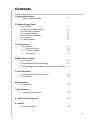
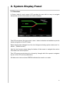
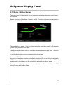
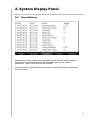
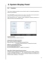
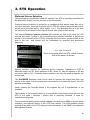
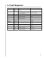
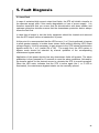
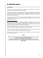
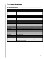
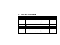
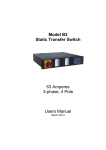
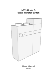
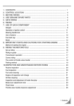
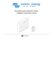
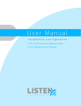
Model W Static Transfer Switch 32 – 100 Amperes 3-phase, 4 Pole Users Manual May 2010 Contents 1. System Description 1.1 Static Transfer Switch 3 2. System Display Panel 2.0 Overview 2.1 Mimic and Status Screen 2.2 LCD Alarm Indication 2.3 Variables Display 2.4 Event History Display 2.5 Controls 2.6 Settings Menu 3. STS Operation 3.1 Overview 1 Preferred Source 2 Controls Override 3 User Access 5 6 7 8 9 10 11 12 14 15 15 4. Maintenance Bypass 4.1 Overview 16 4.2 Installation and commissioning 16 4.3 Reinstatement from Maintenance Bypass Procedure 17 5. Fault Diagnosis 5.1 Interpretation of LCD Event List 19 5.2 Load Fault 21 6. Maintenance 6.1 Overview 22 7. Specifications 8.1 Operating Parameters 8. Main Item Components 23 24 9. Contact 9.1 Contact Details 25 2 1. System Description 1.1 Static Transfer Switch (STS) The Static Transfer Switch (STS) provides power and redundancy to items requiring / having only a single AC supply. The STS selects this supply from one of two input AC supplies. If one of the supply sources becomes unavailable the STS will automatically transfer the critical load to the alternative AC supply source. Manual selection of supply is also possible. This Static Transfer Switch has 3 identical and symmetrical switches, one for each phase of the 3-phase AC supply output. fig. 1. An example of a 3 pole STS This STS implementation uses Break-Before-Make transfer characteristics to ensure that the two sources are never paralleled so that the failure of one supply source has no impact on the other. The supplies can be truly independent. The installed STS is a 4 Pole switch (3-pole only shown in Fig 1) where the neutral is also switched. In the case for the neutral the transfer is overlapping. Upon incoming supply failure or degradation of the selected supply the STS immediately transfers the critical load to the alternative stand-by source. The break time is usually less than one millisecond, however under worst case conditions, can be up to 5 milli-seconds. In the case of down stream load fault conditions, the fault current drawn from the supply may degrade or damage the supply sources; as a consequence should a fault current exist in the load the STS will inhibit a transfer to the alternate source even if this causes source supply degradation or loss. At least the fault will not be 3 1. System Description transferred to the alternate supply with the possibility of degrading both sources. The current threshold for isolation is pre-set and is dependent on factors such as the capacity of the supply sources, line impedance and the line protection schemes employed for each STS. The STS is completely self-contained with its own detection, logic, display and controls. 4 2. System Display Panel 2.1 Overview. A Colour, back-lit, touch screen LCD provides the user with an easy to navigate hierarchical real time information and control interface. fig. 2. The system display panel. The LCD provides a full-colour mimic, alarm / status indication and audible to provide instant recognition of the STS state. Easily identify state changes from the mimic diagram showing system status and / or alarms (Default screen) Use the touch screen zones along the bottom of the screen to navigate the various information and control options. The LCD menus are structured in a hierarchy through which the operator navigates by use of the LCD control pushbuttons. All states are bi-colour where GREEN indicates the normal or on state. 5 2. System Display Panel 2.1 Mimic / Status Screen This menu item provides details on the equipment operating status and event history. STS Status Status summary of the Static Transfer Switch. Provides information on any active alarm or fault conditions. The availability of supply 1 and 2 is indicated by the respective supply LCD diagram (Green being the ON or OK state). The synchronization hold-off LED is located between the two supply bars. Green is in synchronism. 1 and 2 indicate which source is supplying the critical load. An alarm LED indicates an unacceptable, alarm or fault condition. Information as to the cause of the alarm condition is available from the LCD event history or the status LEDs located on the control board on the inside of the front door. The alarm LED and audible alarm (if available) can be cancelled by pressing the Alarms screen. From normal unattended operation a non normal state Clear Indication of ALARM Visual Prompt and Audible Alarm. . 6 2. System Display Panel 2.2 Alarm Indication Alternating visual display of ALARM Condition When indicated the user touches the LCD screen to acknowledge the condition, silence the audible and show the default Status display. The LCD further provides useful real-time information such as supply variables, power quality, event log via a 100 deep, real time, easily understandable event log to provide the user with operational information displays. 7 2. System Display Panel 2.3 Variables Display This menu item shows the input & output variables. Output Voltage R, W & B phase. Output Current R, W, & B phase. Output Power Factor. Output Power (kWatts). Output Power (kVA) Frequency for each source 1 Source Input Voltage R phase. 1 Source Input Voltage W phase. 1 Source Input Voltage B phase. 2 Source Input Voltage R phase. 2 Source Input Voltage W phase. 2 Source Input Voltage B phase. Phase Angle between Sources 1 & 2 8 2. System Display Panel 2.4 Event History Access to the event / Alarms list is available via the “Events” screen selection. To scroll through the events buffer the user again presses the “Events” pushbutton. Up to 100 events can be scrolled. Once the buffer is full the oldest events fall from the buffer and are replaced by any new events. 9 2. System Display Panel 2.5 Controls The control interface provides access transfer and to all essential parameters and set-up information. The TRANSFER control function forms part of the LCD control panel and is accessed using the Control touch zone screen pushbutton. Once pressed the user / operator merely pushes the transfer pushbutton to effect a transfer to the alternate supply. Control Functions LCD control functions enable the user to: TRANSFER BETWEEN SOURCES SET SUPPLY SOURCE PRIORITY GAIN ACCESS TO ALL SETTINGS PARAMETERS (2 levels for each parameter =>manual & automatic) MANUAL /AUTO Mode Selection SYNCH OVERRIDE/BREAK TIMER AUTO RETRANSFER ON/OFF AUTO RETRANSFER DELAY / TIMES TO LOCKOUT Synch Brk & Mode Angle Detection Setting Provides access to adjust the allowable not in synchronism transfer. (Default is 9o and is adjustable between 5o – 30o), Manual transfers are inhibited when supplies are outside this range, however, automatic transfers will experience a 50 msec break, settable (0 – 150 msec). 10 2. System Display Panel 2.6 Settings Menu This menu item provides a facility for adjusting STS settings and calibrations. 2.6.1 Password Restricted access to set-up menus (2 levels of access (000) and (1234). 2.6.2 Date / Time Date and Time adjustment. This menu item displays general information about the equipment. 2.6.3 Communication Settings LAN Web Server and SNMP TCP / network address configuration. 2.6.4 Internal Settings 1, 2 & 3 (Needs Special PASSWORD for access) Access to calibration submenus including: Source 1 Voltage Transient Hi /Lo Steady State Hi / Lo Source 2 Voltage Transient Hi /Lo Steady State Hi / Lo Output Voltage Transient Hi /Lo Steady State Hi / Lo Output Current Overcurrent Threshold Overload I2t (time and current) 11 2. System Display Panel Settings Re-Transfer Delay / no of re-tries Preferred Source Selection Diagnostics 2.6.6 Calibration Menus Used to adjust display accuracy of display variables (only or +/- 2 – 3 volts, follow the prompts, read the accurate value and enter into the Actual column. The user should exercise caution in changing the factory defaults as changing these values or incorrectly setting them could cause unstable or incorrect STS operation. Always ensure that the settings for the STS are wider than the source settings (e.g. mains and UPS). 12 3. STS Operation 3.1 Overview The Static Transfer Switch control panel consists of a touch screen colour LCD display / control panel accessible via the front of the unit. These inform the user information on the operation and status of the equipment. Other than the “Control” functions the LCD menu items cannot change the state of the Static Transfer Switch; this can only be done through the ”Control” menu; transfer pushbuttons, (except when incorrect settings are made). Selection of the required source to supply the critical load is made by simply pressing the transfer pushbutton for at least 2 seconds. Provided the supplies are within synchronization limits, the selected supply will be connected to the load. Verification is provided by the LCD and mimic. If the selected supply should vary outside preset limits and become unusable, the STS will automatically transfer the load to the alternative supply. The preferred source directive (presetable) will ensure that the STS will return to the preferred source if it is available and within acceptable limits, after a settling time. The preference for the preferred source is selectable. (please see over). Maintenance Bypass Switch This switch situated at the top RHS of the unit allows for a maintenance bypass arrangement. The switch is normally in the “N” position and can be used to bypass the internals of the STS to either “Supply Source 1” or “Supply Source 2”. It should be noted however, that operation should only be affected in the direction of the presently operating source. It cannot be used to transfer the critical load from one source to the other. A padlock can be used to stop inadvertent / unauthorized operation. Please read and understand the following section (Section 4) for further information. 13 3. STS Operation Preferred Source Selection The preferred source selection does not operate if the STS is manually transferred to the alternative supply from the controls on the front panel. Preferred source selection is pre-set by a mechanical slide switch inside the unit or via menu selection. Note that at power-up the STS will activate the preferred source, as pre-set by the slide switch, either supply 1 or 2. If no preferred source is set then the unit will not re-transfer to the original source after a fault in that source. The internal Preferred source selection will override any that is set using the LCD controls sub menu. Access to the preferred source selection switches is gained via access to the internals of the STS by removing the front cover via the screws at the side of the unit and should only be undertaken by qualified and authorized personnel. fig. 4. User control panel. These are located within the STS cubicle, bottom RHS of the panel, as shown. Manual transfers override the preferred source selection, (operation of STS to alternate supply say S1 when preferred is S2, where S1 fails will transfer to S2 but not return back to S1). Preferred source selector can also be used to transfer the critical load. The OVERRIDE Selection must not be used to transfer the critical load from one source to the other. Use the preferred source selector to transfer the load if the LCD panel is unavailable. Never operate the Override switch if the supplies are not in synchronism or not available. The purpose of the override switch is to override the control electronics and lock the STS in the state / direction / source that is presently selected. It used for maintenance purposes. Communications ports provide remote voltage free contacts for BMS or remote alarm indication and optional control of the STS from remote. The LAN enables remote viewing of the state of the STS using an internet browser or via SNMP via a Network Management System. 14 3. STS Operation 1. Preferred source selection (pre-set) 0 1 2 No preferred source Supply 1 is the preferred source. If STS is forced to automatically transfer the critical load to the alternate (Supply 2) source the STS will automatically transfer back to Supply 1 when again within tolerance and a pre-set settling delay. Supply 2 is the preferred source. If STS is forced to automatically transfer the critical load to the alternate (Supply 1) source the STS will automatically transfer back to Supply 2 when again within tolerance and pre-set settling delay. 2. Control override (CAUTION: For maintenance only, this should not be used as a transfer control) 0 Normal – Automatic Control Override -> Supply 1 is forced to supply the critical load directly 1 overriding any internal control logic. NEVER attempt to operate the OVERRIDE switch if the supplies are not in synchronism. Control Override -> Supply 2 is forced to supply the critical load directly 2 overriding any internal control logic. NEVER attempt to operate the OVERRIDE switch if the supplies are not in synchronism. 3. User access CAUTION The power cabling should not be run adjacent to user controls. Separate these control cables from power circuits by at least 300 mm. The control signals are distance limited to 30 metres. All output relays contacts are rated for 50 V DC 1 Ampere (Not 230 V AC rated) On DB14 Connector User Remote Inputs (Voltage free contact closure controllers only) Pin 13 to Pin 7 Remote Transfer to S1 Pin 11 to Pin 7 Remote Transfer to S2 User Relay Outputs Relays are normally closed and held open in OK state (closed contact represents the alarm state). Pin 1 to 3 RLY-O/P-ONA Pin 2 to 4 RLY-O/P- Overloaded Pin 5 to 14 RLY-O/P-ON B Pin 6 to 8 RLY-O/P-Not in Synch Pin 10 to 12 General Alarm 15 4. Maintenance Bypass 4.1 Overview The integral maintenance bypass switch should be used when the user is sure that the supplies are both available of the same magnitude and phase. If the STS is on Supply 1 then the maintenance bypass switch should only be operated to position 1. Similarly if the is on Supply 2 then the maintenance bypass switch should only be operated to position 2. If you wish to operate the bypass supply to position 2 then you must operate the STS to Supply 2 using the transfer pushbutton. This is only possible if the STS control logic is operating correctly. In the case of a control failure the STS internal control logic can be overridden and the output can be forced to the correct state using the OVERRIDE switch to position 1 or 2 as appropriate. Remember that the switch needs to be in the centre “O” position for normal operation. The override provides control logic bypass only’ it does not provide an alternative path for the load power. NEVER attempt to operate the OVERRIDE switch if the supplies are not in synchronism. There is no interlock to prevent the switch from being operated when the supplies are not available or not in synchronism. Refer to the LCD variables display and mimic diagram for the not in synchronism state, (SYNC LED will be RED, variables display will show degrees out of synchronism. Only operate when less than 10 degrees). If the control is not operating you may need to use other means to determine that the supplies are in synchronism. Do not operate the OVERRIDE switch onto an absent supply. Do not operate the unit without the fans operating. (63 & 100 Amp units only) CAUTION THIS EQUIPMENT RECEIVES POWER FROM MORE THAN ONE SOURCE. DISCONNECT OUTPUT AND ALL INPUT SOURCES OF POWER FROM THIS EQUIPMENT BEFORE SERVICING. WARNING HIGH LEAKAGE CURRENTS ON ISOLATED INCOMING AND OUTGOING CIRCUITS. EARTH CONNECTION IS ESSENTIAL BEFORE WORKING ON CIRCUITS OR CONNECTING / DISCONNECTING SUPPLIES. SEE INSTALLATION INSTRUCTIONS BEFORE CONNECTING / DISCONNECTING INPUT SUPPLIES. 16 4. Maintenance Bypass Installation and Commissioning Read this whole document thoroughly. Understand every aspect before proceeding. Request further assistance if you do not understand any aspect of the operation of the STS. Support and contact numbers are at the rear of the manual. Consider electrical distribution discrimination carefully. The STS has two incoming AC power isolators your upstream protective devices must discriminate with down stream protective devices and limit the peak fault current to less than 35kA so that when a fault occurs other items connected to the STS are not powered off by the opening of upstream protective devices. The upstream, STS supply breaker /fuse should only open if the down stream device protection is unable to trip or there is a fault within the STS. In case of down stream fault the STS will not transfer the fault to the alternate supply even if the voltage is adversely affected. Once the fault current has cleared the STS will resume normal operation protecting the critical loads from voltage disturbances, (10 second settling time). After following all of the considerations and precautionary processes in the last section and been successful and understanding, then no further special set-up is necessary. Each unit has been fully certified and heat soaked prior to shipment. The ALARM should not be active. If it is check the following states. ON Supply 1 when priority is Supply 2 On Supply 2 when priority is Supply 1 Supply 1 or Supply 2 are not in spec. Override Switch is in position 1 or 2 Supply 1 & 2 are not in synchronism The unit is too hot (thermal bi-metal switch on H.S. activated) There is / was an overcurrent/ overload / load fault condition CAUTION REMOVAL OF PANELS EXPOSES DANGEROUS VOLTAGES ACCESS RESTRICTED TO QUALIFIED PERSONNEL ONLY Ensure from the supply that you are connected to on the STS is also the supply selected by the Maintenance Bypass Switch supply. If you have a remote maintenance bypass then it too should be in the normal position, prior to this step. Go to normal mode (Use switching procedure 3.1.2 to go on line Try using the TRANSFER push button to transfer to the alternate supply. To affect a transfer you need to push and hold the transfer pushbutton for at least 2 seconds. 17 4. Maintenance Bypass The LCD should show that it is now powering the load from the other supply, (non preferred). If unsuccessful or the LCD is not functioning a transfer can be affected using the priority / PREFERRED switch. Simply slide the switch to the desired supply, wait 2 seconds and check the LCD and display to confirm. 18 5. Fault Diagnosis 5.1 Interpretation of LCD event list Event Descriptor INITIALIZE Append WARM BOOT WATCHDOG TIMER Diagnostic STACK EEPROM Diagnostic ROM BATTERY COMMS 1/2/3/4/5/6/ 7/8 CALIBRATION 1/2/3 LOW POWER MODE ON/ OFF S 1 / S2 / S3 AVERAGE V (R,W,B S 1 / S2 / S3 S 1 / S2 /S3 TRANS V (Red, White, Blu) LOW /OK S 1 /S2 /S3 HI / OK SUPPLY 1 or 2 or 3 LOCAL XFER FAILED / OK 0,1, 2 0,1, 2 FREQ LOW / HI /OK 1, 2 REMOTE XFER 1, 2 BACK FEED 1 or 2 on (R, W, B) OFF/ON LOS / OK OVERRIDE PREFERRED S 1 / S2 REMOTE POWER SYNCRONISATION Description RAM CHKsum failed – Cold Start (RAM Corrupt) – Flash Defaults downloaded Power-up, Warm Start, re-initialize all but RAM – Keeps Event List Signals software / hardware problems Stack or Heap has overflowed FLASH/ EEPROM Checksum error – cal may be damaged FLASH ROM has been corrupted (Program is in error) Battery has low power (needs replacing) Communications has failed to Dig Proc, Ana1, Ana2, N1, N2 Calibration of MSP required LOW POWER MODE (Power Down Modes @ loss of electronics power) Supply 1 or 2 OR 3 has Steady State High or Low or phase R, W or B Supply 1 or 2 OR 3 has Transient High or Low (1 sec) STS Action Resulting None - Contact Chloride Supply 1 or 2 OR 3 has Steady State Low (1 sec) Supply 1 or 2 OR 3 has Steady State High (1 sec) Supply 1 or 2 OR 3 has Steady State High (1 sec) Controls Override set to S1 Preferred Source Set (0 or 1) Frequency of supply 2 is high or low Transfers to supply 2 if on 1 Local Transfer to Supply 1 or 2 requested Remote transfer to Supply 1 or 2 requested Back feed voltage too high on S1 or S2 Remote Supply off Requested (EPO) S1 & S2 not in synchronism User - Manual Action Normal After Black Start None - Contact Chloride None - Contact Chloride None - Contact Chloride* None - Contact Chloride* None - Contact Chloride* None - Contact Chloride (can self repair) Contact Chloride * LOW POWER MODES Transfers to supply 2 if on 1 Transfers to supply 2 if on 1 Transfers to supply 2 if on 1 Transfers to supply 2 if on 1 User - Manual Switch Only User - Manual Switch Only Alarm No action Via User Inputs or BMS Contact Chloride Via User Inputs or BMS Alarm No action 19 5. Fault Diagnosis Event Descriptor Append CURRENT WARN / HIGH /FAULT/OK HEAT SINK TEMP HI /OK LOAD FAULT FAN THDI FLT/ CLR FAIL / OK HI / OK THDV HI / OK BREAKER OPEN Q1, Q2, Q3, Q4 or Q5 BREAKER Q1, Q2, Q3, CLOSED Q4 or Q5 TRIPPED Q1, Q2, Q3, Q4 or Q5 ALARM CANCEL POWER SUPPLY 1,2 or 3 SCR SC SCR OC S1,S2 R, W, B, N S1,S2 R, W, B, N Description Output is overloaded (timed shutdown) STS Action Resulting Alarm No action starts timer Fans Failed or Over Stressed Device Temperatures, Heat Sink is Over temperature There was a fault at the load Status Indication Only Total harmonic Distortion of current is very high Total harmonic Distortion of Voltage is too high Status Indication Only No Action – Check & Reduce Loading or Ambient Status Indication Only Status Indication Only Alarm Cancel was pressed Status Indication Only SCR on S1 or S2 short circuit detected on phase # SCR on S1 or S2 Open circuit detected on phase # Does not transfer (Inhibit) No Action - Repair Alarm No Action – Check Load Alarm No action - Check Load Response to interlocking controls Response to interlocking controls Response to interlocking controls Resets Audible & Latched LED None -Contact Chloride / Repair Contact Chloride – Locks to safe source Contact Chloride – Locks to safe source 20 5. Fault Diagnosis 5.2 Load Fault In case of sustained high current output load faults, the STS will inhibit a transfer to the alternate supply even if this means degradation or loss of source supply. It is therefore imperative that you ensure that the discrimination with down stream and upstream protective devices ensures that the downstream protective device always clears the fault first. In case that all output is lost the faulty equipment should be located and removed from the STS output before re-instatement of power. At this point it is recommended that the UPS source (1 or 2) be transferred to bypass to allow greater capacity to isolate down stream faults without affecting UPS output voltage integrity. It will be necessary to gain access to the STS internal maintenance bypass switch for 1 or 2 (switch Q4 or Q5) . The supply from the UPS system in bypass mode should be selected by manual operation of the corresponding maintenance bypass switch. Application of this power should clear any downstream faults still present. The alarm pushbutton is then pressed for 10 seconds to reset the alarm conditions, followed by the transfer switch for the desired source to reinstate the STS to normal operation. When the LED mimic indicates that the STS is active again (the 1 or 2 LED is illuminated), the maintenance bypass isolator can be manually opened. 21 6. Maintenance 6.1 Overview The STS s has been manufactured to provide a long, reliable and useful life. However, all equipment needs some maintenance. After the welcome sign you may be prompted to enter the date and time. This should be required the first time only. We strongly encourage the setting of the date and time so that real time event correlation can be undertaken. The Real Time Clock is thereafter battery backed up. If the STS has been off for 2-3 months awaiting installation the battery requires replacement. We recommend that the battery be replaced every 3 years as a precautionary matter. Recommended Schedule: Once per month record the operating variables and compare with the units specifications to ensure that you are within its operating capability. Inspect the unit and note down any variations from last observation. Action may need to be taken and or reporting may need to be taken on these variances. Inspect the Event History and correlate any recorded events since last observation with real occurrences. Report / investigate any suspicious entries. Once every 6 months, (sooner if the environment is bad), vacuum dust from grills at front of unit. Inspect cable / plug connections for overheating. Units with fans need their fans changed every 3-5 years. This may need to be sooner if the environment is bad. NOTE: Please note that the user should not undertake repair procedures or gains access to the internal of the equipment. If the unit is faulty then it should be removed from service as per the accompanying procedure and a qualified experienced service agent should affect repair. 22 7. Specifications 8.1 Operating Parameters Rating, 3-Phase / phase Voltage Rating Permissible Voltage Distortion Frequency Type Efficiency 20 / 32 / 50 / 63 / 80 & 100 Amperes RMS 230 V ± 20% (115 V AC or Auto ranging available) 15% THDV 50 Hz ± 5% (60 Hz or Auto ranging available on request) 3 Phase + N (true 4-pole, 4 x AC Static Switches /source) 98.9% Transfer Type Detection Break time MTBF Device Ratings Fault rating dV/dt Minimum Current Thyristor (break-before-make, no source overlap, zero current, neutral overlapping) Digital (< 1 msec) Normal; (< ½ msec), Max < ¼ cycle (5msec). > 800,000 Hrs 100 Amperes RMS, 1600 Volts, 2 kA 10msec, 20kA A2S 20 kA 1000 V/µsec 0 Amperes Fault Current Setting Protection Overload Capacity 400% Amperes peak (transfer lock-out) Internal 100 Ampere fuses for 32 Amp unit and 125 Amp fuses for the 100 Ampere unit Up to 120 % for 30 seconds 200 % for 0.5 second 400 Amperes for 100 msec 2000 Amperes for 10 msec User Interface Remote I/O LAN Browser SNMP Modbus Operating Temperature Cooling Physical Size Environmental Rating Weight Colour Hierarchical, Colour, backlit, touch screen real-time monitoring (internal manual override controls) 5 x Voltage free contacts (50 V DC, 1 Ampere N/O) + 2 Transfer Controls Standard Standard Standard, 0 - 45 oC Natural (except > 63 Ampere, redundant forced) 450 W x 200 D x 550H IP41 25 kg (typical) Black Powder Coat / Black front panel (or as specified) Compliance Inlet / Outlet Connections IEC 62310-1,2 & 3 (for STSs), CE Approval Fixed Cassette terminals 25mm2 for 32 & 63 Amp units and 35mm2 conductors for 100 Ampere unit for 3 x 4 core + Earth) 23 9. Main Item Components Part thy1 – 1 to 8 snb1, snb2 q1,q2 f1 & f2 F# main power board main control card colour lcd sp vt card sp firing card sp038r0 bypass switch 32 bypass switch 63 bypass switch 100 main power fuse 32/63 main power fuse 100 prs1-3 Description thyristors dv/dt limiter isolator fans fuses & terminals power control board sts control board display board voltage feedback monitoring board scr gating board user i/o board maintenance bypass switch maintenance bypass switch maintenance bypass switch Semiconductor Fuse Semiconductor Fuse power supply +hd Manufacturer ir sp schneider sunon pheonix i-sts i-sts reach i-sts Part Number sk120kq16 0.22/22 ins40n4, ins63n4, ins100n4 er60/25 12 v dc um04 sp031r1 sp0034r1d 51-0007 sp035r1 Rating 3000 Amps/ 1700 v 1000 v/usec 40/63/100 Amps 12 V dc 10 Amperes 240 v s n/a 63 a 5 v dc n/a i-sts i-sts asn switchgear asn switchgear asn switchgear Busman Trent meanwell sp036r1 sp038r0 wa 143/32e-13 with z32/d2 wa 143/63e-13 with z32/d2 wa 143/100e-13 with z32/d2 FE100 TS125 pd25a n/a n/a 32 Amperes 63 Amperes 100 Amperes 100 Amperes 125 Amperes +5 v / +12 25 w 9. Contact 9.1 Contact Details For Service and Maintenance 25