1
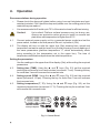
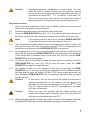
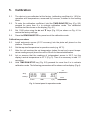
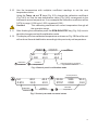
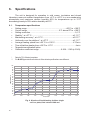
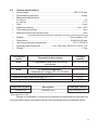
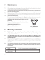
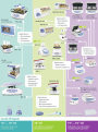
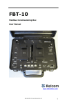
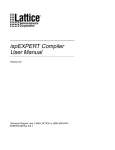
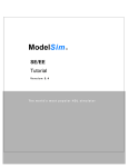
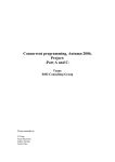
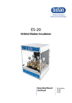
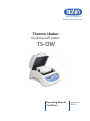
Medical–Biological
Research & Technologies
Thermo-shaker
for deep well plates
TS-DW
Operating Manual
Certificate
for version
V.2A01
Contents
1.
Safety Precautions
2.
General Information
3.
Getting Started
4.
Operation
5.
Calibration
6.
Specifications
7.
Maintenance
8.
Warranty and Claims
9.
Declaration of conformity
1.
Safety precautions
The following symbols mean:
Caution!
Make sure you have fully read and understood the present
Manual before using the equipment. Please pay special
attention to sections marked by this symbol.
Caution!
Hot surface! Platform surface becomes very hot during use.
Always use protective cotton gloves to install or remove test
plate when set temperature is higher than 60°C.
GENERAL SAFETY
Use only as specified in the operating manual provided.
·
·
The unit should be saved from shocks or falling.
·
The unit must be stored and transported in a horizontal position (see
package label).
·
After transportation or storage keep the unit under room temperature for 2-3
hrs before connecting it to the electric circuit.
·
Use only cleaning and decontamination methods recommended by the
manufacturer.
·
Do not make modifications to the design of the unit.
ELECTRICAL SAFETY
·
Connect only to the external power supply unit with voltage corresponding to
that on the serial number label.
·
Use only the external power supply unit provided with this product.
·
Ensure that the power switch and external power supply are easily
accessible during use.
·
Do not plug the unit into an ungrounded power socket, and do not use an
ungrounded extension lead.
·
Disconnect the unit from electric circuit before moving.
·
Disconnect the external power supply unit from power socket to turn off the
unit.
·
If liquid penetrates into the unit, disconnect it from the external power supply
unit and have it checked by a repair and maintenance technician.
·
Do not operate the unit in premises where condensation can form. Operating
conditions of the unit are defined in the Specifications section.
DURING OPERATION
·
Do not leave the operating unit unattended.
·
Do not impede the platform motion.
·
Do not operate the unit in environments with aggressive or explosive
chemical mixtures. Please contact manufacturer for possible operation of the
unit in specific atmospheres.
·
Do not operate the unit if it is faulty or has been installed incorrectly.
·
Do not use outside laboratory rooms.
·
Do not check the temperature by touch. Use a thermometer.
BIOLOGICAL SAFETY
·
It is the user's responsibility to carry out appropriate decontamination if
hazardous material is spilt on or penetrates into the equipment.
2.
General information
Thermo-shaker TS-DW is designed for shaking deep well plates in the
thermostatic regulation mode.
A distinctive feature of BioSan plate thermo-shakers is the patented two-side
plate heating that allows to achieve full correspondence of the set and actual
temperature in the plate wells.
Features of TS-DW meet the highest expectations of users according to many
parameters:
·
Fast reaching of specified mixing speed and maintenance of equal amplitude of
rotation throughout the Thermo-shaker block;
·
Stability of maintaining the set temperature in a wide range throughout the
Thermo-shaker’s block surface;
·
With the help of the temperature calibration function the user can calibrate the
unit approx. ±6% of the selected temperature to compensate differences in the
thermal behaviour of plates from different manufacturers;
·
LCD display indicates set and current values of temperature, speed and time of
operation;
·
Quiet motor operation, compact size, prolonged service life.
TS-DW was designed using the multi-system principle, which allows using it as
three independent devices:
·
Incubator
·
Plate shaker
·
Thermo-shaker
The device can be used in:
·
cytochemistry
—
for in situ reactions;
·
immunochemistry
—
for immunofermentative reactions;
·
biochemistry
—
for enzyme and protein analysis;
·
molecular biology
—
for nucleic acids isolation.
3.
Getting started
3.1.
Unpacking
Remove packing materials carefully and retain for future shipment or storage of
the unit. Examine the unit carefully for any damage incurred during transit. The
warranty does not cover in-transit damage.
3.2.
Complete set. Thermo-shaker set includes:
Standard set
TS-DW Thermo-Shaker for deep well plates ..........................................1 pce
external power supply unit........................................................................1 pce
power cord ...............................................................................................1 pce
spare rubber belt ......................................................................................2 pcs
Operating Manual; Certificate ..................................................................1 pce
Optional accessories
thermal block -2E for Eppendorf deep-well plates.............................on request
thermal block B-2S for SarstedtB deep-well plates ...........................on request
3.3.
Set up:
place the unit upon even horizontal non-flammable surface 30 cm away from
any flammable materials;
remove protective film from the display;
plug the external power supply unit into the socket at the rear side of the
unit;
connect the power cord to the external power supply unit.
3.4.
Thermoblock installation (if thermoblock is not installed)
Caution!
Thermoblock installation and replacement have to be
performed only when the Power switch is turned off and
external power supply is disconnect from the device.
Choose the thermoblock, connect the plug to the
contact terminal according to the scheme on Fig.1/1
on the underside of the thermoblock. Make sure
that the connector is mounted tightly.
Align the thermoblock so that the connector pins
are facing the right side of the unit.
Secure with the four knurled screws.
1
Fig. 1 Thermoblock
connection
Changing blocks
Disconnect the external power supply unit from the device.
Remove the four knurled screws, lift the block without damaging the cable
and disconnect the plug (fig.1/1).
Select the new thermoblock and install it according to the point 3.4.
3.5.
4.
Operation
Recommendations during operation
·
Please check the deep well plates before using, be sure that plates are heat-
resistant resistant. Don't heat the deep well plates over the melting point of the
material they are made of.
·
It is recommended to fill wells up to 75% of the rated volume for efficient mixing.
Caution!
Hot surface! Platform surface becomes very hot during use.
Always use protective cotton gloves to install or remove test
plate when set temperature is higher than 60°C.
4.1.
Connect external power supply unit to a grounded power socket and set the
power switch, located on the rear panel of the unit, to position I (ON).
4.2.
The display will turn on with the upper line (Set) showing time, speed and
temperature set earlier and the lower line (Actual) showing current readings of
the same parameters (platform temperature °C, which automatically starts
rising according to the temperature set in the upper line). The time of
temperature stabilisation depends on the initial temperature.
Setting the parameters
Use the readings in the upper line of the display (Set), while setting the required
parameters.
4.3.
Setting time (TIME). Using the p
and q
keys (Fig. 2/1) set the required
working time interval in hours and minutes (increment - 1 min). Pressing the key
for more than 3 sec will increase the increment rate.
4.4.
Setting speed (RPM). Using the p
and q
keys (Fig. 2/2) set the required
speed (increment 10 rpm). Pressing the key for more than 3 sec will increase
the increment rate.
4.5.
Setting temperature (Т, ºС). Using the p
and q
keys (Fig. 2/3) set the
necessary temperature (increment 0.1°C). Pressing the key for more than 3 sec
will increase the increment rate.
00:00 1400
STOP 0000
25.0
25.0
Thermo-Shaker
for deep well plates
Fig. 2. Control Panel
Caution!
Heating/temperature maintenance process does not stop
when the timer is finished. Platform thermal regulation can be
turned off only by setting the required temperature below 25 °C
(the display will show OFF - T,°C - set point). In this mode TSDW can be used in the cold rooms as a mixing device without
thermoregulation. Settings can be changed during operation.
Program execution
After the thermal stabilisation of the Thermo-Shaker (when the set and current
temperature readings become the same):
4.6.
Place the deep well plate on the platform and close the lid.
4.7.
Press the RPM-RUN/STOP key (Fig. 2/4). The platform will start rotating and
the timer indicator will start counting up the time interval (with 1 min precision).
Note!
If the rotation speed is set to zero, pressing RPM-RUN/STOP
key will start the timer but the platform will not move.
4.8.
After finishing the program (after the set time elapses) the platform motion will
stop and the timer will show the flashing reading STOP accompanied by the
repetitive sound signal until the RPM-RUN/STOP key is pressed.
4.9.
If the working time is not set (or is reset) and the timer indicator in the upper line
shows 00:00, pressing the RPM-RUN/STOP key will start continuous operation
of the device with countdown timer in the lower line (Actual) until the RPMRUN/STOP key is pressed again.
4.10. If required, there is possibility to restart the timer when it is running. Press the
TIME-RUN/STOP key once (Fig. 2/5) to stop the timer. Press the TIMERUN/STOP key again to restart the timer.
4.11. The platform motion can be stopped at any time by pressing the RPMRUN/STOP key. In this case the program realisation and the platform motion
will stop and the timer will switch into the STOP mode saving previously set
time. Press the RPM-RUN/STOP key to repeat the operation with the same
time and speed.
Caution!
At the end of the set time period the platform movement is
stopped automatically, but the heating can be stopped only
manually by reducing the temperature using the q
T,°C key
(Fig. 2/3 - lower button) till the OFF sign appears in the upper
line (Set) of the display
Caution!
When lid is open the platform and lid heating surfaces will
remain hot. Please, take necessary care and use protective
cloth gloves at temperatures over 60°C.
4.12. After finishing the operation set the power switch, located on the rear panel of the unit,
in position O (Off) and disconnect the external power supply from electric circuit.
5.
Calibration
5.1.
The device is pre-calibrated at the factory (calibrating coefficient is 1.00) for
operation with temperatures, measured by a sensor, installed in the heating
block.
5.2.
To enter the calibration coefficient, hold the TIME-RUN/STOP key (Fig. 2/5)
pressed for more than 8 s to activate calibration mode. The calibration
coefficient will be shown on the display (Fig. 4/1).
5.3.
Set 1.000 value using the p
and q
keys (Fig. 2/3) as shown on Fig. 4/1 to
restore the factory settings.
5.4.
Press the RPM-RUN/STOP key once to exit the calibration mode.
Calibration procedure
5.5.
Install autonomic sensor (0.5°C accuracy) into the plate well placed on the
platform. Close the lid.
5.6.
Set the required temperature in operation mode (e.g. 40°C).
5.7.
After the unit reaches the set temperature (when the set and current temperature readings equal) leave the unit for 30 min for thermal stabilization.
5.8.
Let us assume that the readings of independent sensor is 39°C, but the
display’s actual temperature is 40 °C (Fig. 3). Then it is necessary to add 1°C
correction.
5.9.
Hold TIME-RUN/STOP key (Fig. 2/5) pressed for more than 8 s to activate
calibration mode. The following parameters will be shown on the display (Fig.4):
set
temperature
Set p.
Actual p.
00:00
STOP
1000
0000
hr:min
RPM
40.0
40.0
o
T( C)
actual
temperature
Fig. 3 Control panel in operation mode
5.10. Use the temperature with multiplier coefficient readings to set the new
temperature value.
Using the Temp. p
and q
keys (Fig. 2/3), change the calibration coefficient
(Fig. 5A/1) so, that the new temperature value (Fig. 5A/2) corresponds to the
autonomic sensor temperature. In our example the calibration coefficient will be
0.974 (in range: 0.936 up to 1.063; increment 0.001).
Caution!
This calibrating coefficient will correct temperature through all
the operation range.
5.11. After finishing the calibration press the RPM-RUN/STOP key (Fig. 2/4) once to
save the changes and exit the calibration mode.
5.12. The display will show calibrated temperature as shown on Fig. 5B/3 and the unit
will continue thermal stabilization according to the previously set temperature.
calibration
mode
sct.
1.000
calibration
coefficient
40.0
40.0
modified
temperature
set
temperature
inner sensor
temperature
40.0
40.0
actual temperature multiplied
by previous coefficient
Fig. 4 Control panel in calibration mode
set temperature
sct.
0.974
40.0
39.0
calibration
coefficient
40.0
40.0
modified
temperature
00:00
STOP
1000
0000
40.0
39.0
calibrated
temperature
Fig. 5 Control pane and corrected values
11
6.
Specifications
The unit is designed for operation in cold rooms, incubators and closed
laboratory rooms at ambient temperature from +4°C to +40°C in a non-condensing
atmosphere and maximum relative humidity 80% for temperatures up to 31°C
decreasing linearly to 50% relative humidity at 40°C.
6.1.
Temperature specifications
·
Setting range ........................................................................+25°С to +100°C
·
Control range ...........................................................5°С above RT to +100°C
·
Setting resolution ....................................................................................0,1°С
·
Stability*, at +37°C.............................................................................±0.1°C**
·
Maintaining accuracy*, at +37°C........................................................±0.5°C**
·
Uniformity over the platform*, at +37°C .............................................±0.1°C**
·
Average heating speed from +25°С to +100°С...................................4°С/min
·
Time of platform heating from +25°С to +37°С .........................................4 min
·
Temperature calibration option
·
Calibration coefficient range .........................................0.936...1.063 (± 0.063)
*
**
Data for 75% filled microplates
For B-2E Eppendorf thermoblock. Other block specifications are different.
100
95
90
85
80
Temperature, °C
75
70
65
60
55
50
45
40
35
30
25
20
0:00
0:30
1:00
1:30
2:00
2:30
3:00
3:30
Time, h:mm
Fig. 6. Kinetics of liquid heating inside a single
cell in a plate, total volume 1000 mcl
12
4:00
4:30
6.2.
General specifications
·
Speed range..............................................................................250–1400 rpm
·
Speed setting resolution ........................................................................10 rpm
·
Maximal speed deviation
for 250 rpm .................................................................................................................2%
for 1400 rpm ............................................................................................................0.7%
·
Orbit ........................................................................................................2 mm
·
Digital time setting ..........................................................................1 min – 96 h
·
Time setting resolution .............................................................................1 min
·
Maximal continuous operation time............................................................96 h
recommended interval between operation sessions not less than 8 hours
·
Display...............................................................................16x2 symbols, LCD
·
Dimensions..........................................................................240x260x160 mm
·
Input current/power consumption ............................................12 V, 3,7 A/45 W
·
External power supply unit ....................in AC 100-240 V 50/60 Hz, out DC 12 V
·
Weight*...................................................................................................5.1 kg
Thermoblock
model
B-2E
Thermoblock description
Catalogue
number
BS-010159-AK
for Eppendorf deep well 96/1000 µl
microplates
Block parameters is in section 6. specification.
B-2S
for Sarstedt MegaBlock
BS-010159-CK
deep-well microplates, 96 x 2,2 ml wells
Temperature maintenance stability, at +37°С
±0,1°С
Temperature maintenance precision, at +37°С
±1,0°С
Uniformity over the platform, at+37°С
±0,2°С
Replacement parts
Description
Catalogue number
Rubber belt
122x6x0,6 mm
BS-000000-S18
* Accurate within ± 10%.
Biosan is committed to a continuous programme of improvement and reserves
the right to alter design and specifications of the equipment without additional notice.
13
7.
Maintenance
7.1.
If the unit requires maintenance, disconnect the unit from the electric circuit and
contact Biosan or your local Biosan representative.
7.2.
All maintenance and repair operations must be performed only by qualified and
specially trained personnel.
7.3.
Standard ethanol (75%) or other cleaning agents recommended for cleaning of
laboratory equipment can be used for cleaning and decontamination of the unit.
7.4.
Rubber belt replacement:
For maintenance of reliable operation of the device the producer recommends
to replace rubber belts after 1.5 years or 2000 hours of operation time.
Disconnect the external power supply unit from
the device.
Remove 4 fixation screws on the device bottom
and remove the bottom plate.
Replace the rubber belt (Fig. 7).
Re-assemble the device.
Fig. 7. Rubber belt
replacement
8.
Warranty and Claims
8.1.
The Manufacturer guarantees the compliance of the unit with the requirements
of Specifications, provided the Customer follows the operation, storage and
transportation instructions.
The warranted service life of the unit from the date of its delivery to the
Customer is 24 months. Contact to your local distributor to check availability of
extended warranty.
If any manufacturing defects are discovered by the Customer, an unsatisfactory
equipment claim shall be compiled, certified and sent to the local distributor
address. Please visit www.biosan.lv, Technical support section to obtain the
claim form.
The following information will be required in the event that warranty or postwarranty service comes necessary. Complete the table below and retain for
your records.
8.2.
8.3.
8.4.
Model
Serial number
Date of sale
14
TS-DW Thermo-shaker for deep well plates
9.
Declaration of conformity
Version 2.01 - December 2014