1
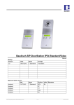
Rack User Manual Remote Control Interface RCI10 Date of issue: Date of publication: August 2015 This document replaces the following documents: New Edition Editor: E-T-A Elektrotechnische Apparate GmbH Industriestraße 2-8 . D-90518 Altdorf GERMANY Phone +49 9187 10-0 . Fax -49 9187 10-397 E-Mail: [email protected] . www.e-t-a.de Copyright © 2015 E-T-A GmbH The contents of this document are the property of E-T-A GmbH. No part of this publication must in any way be reproduced or distributed without prior written consent of E-T-A GmbH. Any person acting illegally with regard to this publication can be prosecuted. Limitation of liability Although all provisions were taken when creating this document, the editor does not accept any responsibility for errors or omissions or for damages caused by using the information contained in this document. The information contained in this document may be revised at any time without advance notice. Brands All references to software and hardware in this document are generally protected by brands or patents. © E-T-A GmbH 2015. All rights reserved 2 About this manual This manual describes the configuration for start-up and the operation of the integral SSH, web browser and SNMP interfaces by means of a control and configuration PC connected to the Remote Control Interface RCI10. The RCI10 sub-assembly provides ease of monitoring and remote control of the ControlPlex® Rack system in connection with a control computer or a management system. Typical application is mainly the control and monitoring of decentralised telecommunication systems. Besides this document, more information about the E-T-A ControlPlex® Rack can be found in the following documents. ControlPlex® Rack Data sheet Here you will find more technical data and figures as well as approval information on the various components of the ControlPlex® Rack system ControlPlex® Rack Installation and operating instructionsHere you will find the instructions for installation and start-up of the hardware of the ControlPlex® Rack system as well as helpful information for component replacement and trouble-shooting on site. The latest documents can be found on our website under: www.e-t-a.de/controlplex_rack All documents contain important instructions for connection and safe operation of the ControlPlex® Rack system. Safety instructions have to be observed. All users have to be informed about all safety instructions. The documents have to be accessible for the user. 3 General note Qualified personnel The system must only be installed, connected, configured and operated in connection with the above mentioned documentation. Installation and operation of the device/system must only be carried out by qualified personnel. With regard to the safety instructions of this documentation, qualified persons are persons authorised to operate devices, systems and circuits according to the standards and rules of safety engineering. Safety instructions Please follow the instructions given in this document carefully. Failure to comply may lead to serious damages of the product or the system. E-T-A does not accept any liability for problems caused by improper installation or handling by the customer or a third person. Symbols You will find the following symbols in the entire manual. Their meaning is as follows: Danger! You are in a situation which might cause injury. Before working on a device, you have to be aware of the hazards connected with electrical circuitries and you have to be familiar with the standard procedures of accident prevention. Warning There is a risk in this situation to do something which might cause damage of the devices or data loss. Note Here you receive information which might be particularly useful for the application. 4 Contents About this manual............................................................................................................................................3 General note.....................................................................................................................................................4 Contents ..........................................................................................................................................................5 1Introduction.......................................................................................................................................������6 2 Minimum requirements for start-up of the RCI10 sub-assembly ................................................������7 3 Important information and safety instructions ....................................................................................7 4 Schematic system design and network connection............................................................................8 5 General: RCI10 Start-up with web browser surface.............................................................................9 5.1 Start-up: Useful information on the web browser surface................................................................9 5.2 Start-up: IP settings on the configuration PC.................................................................................10 5.3 Start-up: Status and installation of the hardware...........................................................................10 5.4 Start-up: Starting the web browser surface....................................................................................10 5.5 Start-up: Configuration by means of web browser surface............................................................12 6 General: RCI10 Start-up with the SSH v2 surface..............................................................................13 6.1 SSH tools: Installation SSHv2 Client programme LePutty©............................................................13 6.2 SSH tools: Installation SSHv2 Client programme LePutty©............................................................13 6.3 Start-up: Configuration via SSH surface.........................................................................................14 6.4 Start-up: Table of SSH configuration parameters and factory settings..........................................16 6.5 Start-up: RCI10 configuration file download..................................................................................18 6.6 Start-up: RCI10 configuration by means of configuration file uploads...........................................20 7 General: RCI10 Additional functions SSH surface..............................................................................20 7.1 Operation of the SSH surface: Display RCI10 inventory data........................................................21 7.2 Operation of the SSH surface: Download of log data and measuring data file..............................21 7.3 Operation of the SSH surface: Reset to factory settings................................................................22 7.4 Operation of the SSH surface: RCI10 software update / upgrade.................................................22 8 General: RCI10 Operation with web browser......................................................................................22 8.1 Operation with web browser: Function of the mask “Fuse Control”..............................................22 8.2 Operation with web browser: Function of the mask “Feed Settings”.............................................24 8.3 Operation with web browser: Function of the mask “Fuse Settings”.............................................25 8.4 Operation with web browser: Function of the mask “System Log”................................................27 8.5 Operation with web browser: Function of the mask “Error Log”....................................................28 8.6 Operation with web browser: Function of the mask “Fuse Log”....................................................29 9 General: RCI10 operation with management system.........................................................................29 9.1 Operation with management system: Settings in the RCI10 sub-assembly..................................30 9.2 Operation with management system: Embed SNMP MIB..............................................................31 10 Appendix: List of pictures.....................................................................................................................32 11 Appendix: List of abbreviations............................................................................................................33 12 Appendix: Legal references and licences............................................................................................34 13 Appendix: Template of configuration table.........................................................................................35 14 Appendix: Example RCI10 configuration file (excerpt)......................................................................38 Notes...............................................................................................................................................................39 5 1Introduction You chose ControlPlex® Rack, a comprehensive, future-oriented protection system which combines safety, user convenience and service friendliness. It is a power distribution, measurement and control system which provides electronic and, in the event of a short circuit, current-limiting protection of various loads. By means of an internal bus system and an additional, hot-pluggable control interface module (optional), each load can remotely be controlled and monitored. In addition it allows recording of measuring data of every single load. Besides providing overcurrent and short circuit protection, it increases system availability by a multiple, because it disconnects faulty loads quickly, selectively and without voltage dips. In connection with the control interface module type RCI10 the ControlPlex® Rack system can be connected to a centralised management system (control computer). For this purpose an Ethernet interface is made available with SNMP v1, v2c or v3 protocol. The required private MIB for embedding is part of the delivery scope. An additional possibility for a centralised or also local monitoring/control is provided by the integral web server, which can be used without additional software on the control computer by means of the web browser. In addition great importance was attached to system security, against illegal access. Therefore the configuration of the RCI10 sub-assembly is effected via a secure Secure Shell (SSH) surface. It also offers a great number of configuration options to increase system security. Thanks to its system properties the ControlPlex® Rack is the perfect solution for smart protection, control and energy measurement for DC-supplied minus switching system cabinets. Typical applications include • System cabinets of any kind in telecommunications with DC -48 V or DC -60 V rated supply • Server cabinets in IT centres with equipment for DC -48 V or DC -60 V rated supply • System cabinets for mobile radio and television for DC -40 V to DC -72 V • Protection and control of illuminated advertising with a power supply of DC -48 V Further descriptions of the ControlPlex® Rack systems - mounting and connection procedures for the hardware as well as an instruction for start-up and trouble-shooting of the individual components can be found in the manual ControlPlex® Rack mounting and operation instructions. This document contains a configuration and operation instruction for the software of the Remote Control Interface sub-assembly RCI10. You will learn more about •How to configure the RCI10 sub-assembly via the SSH surface for the first operation and how to adjust it to your requirements. •How to use the integral web surface for monitoring and controlling the ControlPlex® Rack; system • How to embed the ControlPlex® Rack system into a management system 6 2 Minimum requirements for start-up of the RCI10 sub-assembly Please check if the components of the ControlPlex® Rack system were completely installed and work faultlessly, see document „ControlPlex® Rack: Installation and operation instructions“. You require the following tools for configuration and start-up: • PC with Ethernet interface (LAN) and operating system Windows 7.x or higher • P re-installed internet browser such as IE from v9 or Mozilla Firefox from v28.8, please also see data sheet ControlPlex® Rack. • Ethernet cable 10 / 100 Mbit (standard network cable) in the required length. 3 Important information and safety instructions The following table lists various information and safety instructions for start-up and use of the device. Danger: Installation and operation of the device This device has to be installed and operated in compliance with the given instructions. Failure to comply can lead to injury, damage of loads or of the ControlPlex® Rack. Danger: Turn off the supply voltage Before beginning with installation, the system has to be disconnected from the mains. A cable connection must only be established if the supply voltage is OFF. Danger: Possible ignition hazard The device must NOT be used in inflammable surroundings. Danger: High voltage The cover must NEVER be opened. Access to the inner components is not allowed unless indicated otherwise in this manual. Caution: Work with ESD protection Electronic modules must only be touched and installed with ESD protection so as to ensure protection against electrostatic voltage. Failure to comply can cause damages on the ControlPlex® Rack system or the corresponding components. Caution: Grounding The device must be grounded before switching on. Table 1: Important information EMC Installation Guidelines The ControlPlex® Rack hardware and accessories comply with the EMC directives. Thus electromagnetic interferences between the devices are avoided which would otherwise affect the system performance. A professional installation is mandatory. In order to ensure the best EMC conditions, the widest possible distance between the different electrical devices should be applied. Technical Accuracy All technical data in this manual were correct in all conscience at the time of printing. E-T-A cannot be held liable for any (inadvertent) errors. Due to continuous product improvements at E-T-A there could be discrepancies between the actual product and the manual. Product changes or amendments of the technical specifications will be carried out without prior notification. The latest versions of the ControlPlex® Rack documents are available on our website (www.e-t-a.de). 7 4 Schematic system design and network connection Schematic diagram of entire system ControlPlex® Rack + - Ethernet (RJ45) Ethernet Interface backplane/ ESX300-S (19) line (-) line (+) EL-BUS RED Remote Control Interface RCI10 power + load line line Sig. (C)/EL-Bus Sig. (NC) Circuit Protector ESX300-S (1) + - line entry / supply (LINE) load (1) . . . . . . . . . . . . . load (19) Fig. 1: Schematic diagram ControlPlex® Rack Connection example SNMP v1, v2c, v3 (HTTP(S)/SSH) management system / main computer intranet ControlPlex® Rack PDB-N-CP RCI10 (S TP HT Power SH )/S router Ethernet cable load-1 load-2 load-3 configuration PC Fig. 2: Connection example ControlPlex® Rack 8 system cabinet ESX300-S 5 General: RCI10 Start-up with web browser surface The web server included in the RCI10 sub-assembly offers an easy and convenient option of adjusting the RCI10 sub-assembly and the ControlPlex® Rack system to your requirements during start-up. An extended configuration (for enhanced security settings of various protocols) can be carried out via the SSH surface. If you do not want to use the web browser surface, you may skip this chapter. Continue with chapter 6 General: RCI10 Start-up with the SSH v2 surface. The web browser surface provides the following adjustment options for network and start-up configuration: Configuration: • IP address data • Web browser: log-on data • System time • Settings of the ControlPlex® Rack system - specific system designations • Setting the system language of the web browser surface 5.1 Start-up: Useful information on the web browser surface For using the web server function you only need a web browser on your PC. We tested the following browsers with regard to correction function and display: • Internet Explorer Version 9 • Mozilla Firefox Version 28.8.1 • Google Chrome Version 26.0 You are of course free to use other web browsers or versions of the above listed browsers. However, in such a case we cannot ensure that all charts of the web browser surface will be shown correctly. 9 5.2 Start-up: IP settings on the configuration PC Before starting configuration, you have to check the IPv4 Ethernet settings on the configuration PC and amend them if required. For this purpose connect your PC with a LAN (Ethernet) cable to the RJ45 connector of the RCI10 sub-assembly. The IPv4 Ethernet address of your configuration PC has to be as follows: 192.168.0.xxx Comment: xxx = 1 … 24, 26 … 254 (the address 192.168.0.25 is occupied by RCI10, factory settings). Example: Set an IPv4 address at the configuration PC, e.g. IPv4 = 192.168.0.20 Fig. 3: IPv4 setting configuration PC 5.3 Start-up: Status and installation of the hardware. The ControlPlex® Rack system with the components ESX300-S circuit protector and RCI10 Remote Control Interface was installed correctly as described in the ControlPlex® Rack Mounting and Installation Instructions“. The LED status is as follows: • RCI10 status LED: shows green • ESX300-S fault LED(s): OFF • ESX300-S OK LED(s): blink slowly or show green Your PC is connected with a LAN (Ethernet) cable to the RJ45 connector of the RCI10 sub-assembly. The PC and RCI10 sub-assembly can also be interconnected via a network, e.g. router. For this purpose please ensure that the RCI10 IPv4 factory pre-set address has not yet been assigned otherwise in your local network. For a list of all factory settings please see table 2, SSH configuration parameter list and factory settings 5.4 Start-up: Starting the web browser surface •Open a web browser window on your configuration PC e.g. with: Internet Explorer or Mozilla FireFox etc. • Enter the URL: https://192.168.0.25 in the address line and confirm with the Return button •Should a warning message appear such as „Problem with the security certificate“, please confirm with continue or continue loading of the indicated page. •Enter user name and password. The factory pre-set user name is user, password: user1234. Confirm with OK 10 Fig. 4: Web browser login IE •The web browser surface opens with the tab: Fuse Control of the RCI10 sub-assembly. Depending on the version of the ControlPlex® Rack system, the appearance may slightly differ, whether you installed a redundant system or not. Fig. 5: Web mask “Fuses” •Click on the tab Configuration on the left side of the surface. The configuration window System Settings opens. Fig. 6: Web mask “Configuration / System settings” 11 5.5 Start-up: Configuration by means of web browser surface The web browser configuration window shows the presently active factory settings. The tab Configuration contains three tabs (System Settings, Feed Settings, Fuse Settings). This chapter describes the setting options of the System Settings Please note that, depending on the internal factory-set configuration or the configuration carried out by you via the SSHv2 interface, some functions may not be available. Please make a note of all configuration changes with the newly entered values. Please carry out the following adjustments in the category HTTP: • Change the user name under Login • Change the password under Password The password is not shown (asterisks). No password is set in the event of no entry. •Change the display language if required under Language. You can choose between the languages German and English. In the category ETHERNET you can e.g. adjust the IPv4 address settings. In addition you can •Activate the DHCP protocol (Dynamic Host Configuration Protocol) in your local network. Please select the check box Use DHCP. After activation of the changed settings the DHCP protocol will automatically assign a new IPv4 address to the RCI10 sub-assembly. Please make a note of this address if you wish to connect your configuration PC again with the system at a later date (without network). You then have to enter https://<new IPv4 address> as URL into the address bar of the web browser. <new IPv4 address> = the above noted address. hould you deactivate the check box Enable v4, no IPv4 address will be considered valid any longer, i.e. you S do no longer have access to the RCI10 sub-assembly via IPv4. You will then always have to indicate an IPv6 address. • If your network does not support IPv6, we recommend deactivating the check box Enable v6. •If a DNS server (Domain Name Server) is available in your network, please enter the DNS URL under DNS Server. In the category MISC you can • enter a name for the ControlPlex® Rack system (System name). • indicate a contact person (System contact) • indicate an installation site (System location) •In addition you can determine the time zone (Time zone: 1 = CE winter time, 2 = CE summer time) and changeover summertime/wintertime (DST). Date and clock time cannot be set because the factory settings include an NTP server (time server, network time protocol). The RCI10 sub-assembly will automatically get the valid time information from the NTP server. It may, however, happen that the NTP server cannot be reached by your local network, see chapter: 6.4 Startup: Table of SSH configuration parameters and factory settings • Click on SAVE to save the changed values. If you do not save, all changes will be lost. •Click on the button REBOOT: EXECUTE to activate all changes, confirm with OK. The RCI10 sub-assembly carries out a reset with a re-load of the changed parameters. Re-booting may take up to 60 seconds. During this time you do not have a connection to the RCI10 sub-assembly. 12 The reset will not affect the plugged in circuit protectors ESX300-S, i.e. your connected loads remain active during the RCI10 re-start. •Re-load the page in your web browser after approx. 60 seconds. Click on the Reload function of the web browser. Now all carried out changes should be activated and visible. 6 General: RCI10 Start-up with the SSH v2 surface Secure Shell or SSH is the name of a network protocol and of corresponding programmes. For the purpose of a safe, encrypted connection between the configuration PC and the RCI10 sub-assembly, also via an unsafe network, the SSH surface can be used both for a comprehensive configuration of all parameters and for upload and download of data such as measuring and log data. The SSH surface offers you the full scope of configuration options of the RCI10 sub-assembly. This is particularly relevant for higher requirements of system safety. For a list of all factory settings please see table 2, SSH configuration parameter list and factory settings. 6.1 SSH tools: Installation SSHv2 Client programme 1LePutty© In order to be able to establish a safe SSH v2 connection, you require a terminal programme called SSH Client. The SSH Client programme has to be installed on the PC used for configuration. We recommend the freeware programme 1LePutty©, which is available for download on our website www.e-t-a.de/controlplex_rack. The configuration of the SSH Client mentioned below exclusively refers to this version. •After downloading the compressed file “CP-RCIxx_SSH-Client_Vxx.zip” unpack into a suitable directory on the hard disk drive of your configuration PC. • 6.2 Among the unpacked files there is a file named E-T-A_Readme.txt, holding all information required for installation. Please follow the instructions given in this file. SSH tools: Installation SSHv2 Client programme 1LePutty© To allow use of the full functional scope of 1LePutty©, you have to configure the programme as follows: 1.Start the programme by clicking on the programme icon Putty©. Carry out the steps 1 to 3 on right side of fig. 7; IP configuration 1LePutty©. 1) Mark the menu item “Session” in “Category” 2) Mark in menu item “Saved Session” the file: RCI10_Config-Vxx 3) Click on button: Load Fig 7: IP configuration 1LePutty© 1 see chapter 12: Legal references and licences 13 2.Configure the ZModem settings, see fig. 8 bottom. Carry out the steps 1 to 5 beside the picture left and right. 1) Mark the menu item „ZModem“ in „Category:“ 2) Click on button Browse. A browser window opens. Navigate and mark the file saved in chapter 6.1 rz and click on open 5) Enter the values -e -v in the fields “Options” 3) Click on button Browse. A browser window opens. Navigate and mark the file saved in chapter 6.1 sz and click on open 4) Click on button Browse A browser window opens. Select the directory where you wish to save the ControlPlex measuring and configuration data. Fig. 8: ZModem configuration LePuTTY • Mark the menu item Sessions in “Category”, see fig. 7, IP configuration LePuTTY top •Click the button Save to save the carried out ZModem settings in the configuration file RCI10_Config-Vxx. 6.3 Start-up: Configuration via SSH surface Before starting configuration, you have to check the IPv4 settings on the configuration PC and amend them if required, see chapter 5.2 Start-up: IP settings on the configuration PC 1. S tart the programme 1LePutty© and load the saved configuration file RCI10_Config_Vxx as described in chapter 6.2, paragraph 1. 2. C lick on the button Open in the 1LePutty© window. The programme will now build up a connection to the RCI10 sub-assembly and open an SSH window. 3. A uthenticate yourself with User: user and password: user1234 (factory settings). You now see the SSH configuration menu. 14 Fig. 9: SSH main menu The “Cursor” buttons () allow navigation in the menu, menu items can be selected with the “Enter” button. Parameters can be changed by the “ + / -” buttons (e.g. Yes / No) or adjusted by direct entry of the value (e.g. name). The “F1” buttons helps to leave a submenu and to close the SSH connection in the top menu. 4. A list of all SSH configuration parameters with a short description can be found in chapter 6.4. below Please make a note of all configuration changes with the newly entered values. For this purpose you can print the table inserted in chapter 13 and enter the values manually. After changing configuration settings you have to select the menu option „Reboot RCI10“ in the SSH menu so that the changes are activated. Re-boot can also be effected by pressing the reset button of the RCI10 sub-assembly for 3 seconds on site. Re-boot is visually indicated by the green LED going out. The RCI10 can be accessed again approx. 60 seconds after initiation of the re-boot. The reset will not affect the plugged in circuit protectors ESX300-S, i.e. your connected loads remain active during the RCI10 re-start if the configuration value “status after reset” was set to “ON” in the web browser surface or was not activated, see chapter 8.3, operation with web browser: Function of the mask “Fuse Settings” If you changed the IP address of the RCI10 sub-assembly, you are no longer able to open the RCI10 SSH surface. For this purpose you need to enter the changed RCI10 IP address also in the 1LePutty© programme, see 1LePutty© window, fig. 7; IP configuration 1LePutty© “Host Name (or IP address)”. Save the change by clicking on the button “Save” in the 1LePutty© window. 1 see chapter 12: Legal references and licences 15 6.4 Start-up: Table of SSH configuration parameters and factory settings Description of all available SSH configuration parameters including the factory setting when delivered. Please note that, depending on the internal factory-set configuration or the configuration carried out by you via the SSHv2 interface, some functions may not be available. SSH settings Setting parameters Description Factory settings SSH user login Defines the user name (user ID) for the SSH login. Permitted characters: 20 characters [a-z; 0-9; _-]. user SSH user password Defines the password for the SSH login. Please observe upper and lower case. Permitted characters: 110 characters [a-z; A-Z; 0-9; $/.] user1234 HTTP settings Setting parameters Description Factory settings HTTP enable Activation web server Allow access via web browser. Possible values {Yes; No}. Yes Access only using HTTPS Web browser access only via HTTPS protocol possible (encrypted transmission). Possible values {Yes; No}. Yes Allow settings write Parts of the configuration settings such as http/login, IP address etc. can be changed directly via webbrowser. Possible values {Yes; No}. Yes Allow fuse switch via HTTP Determines if the circuit protectors may be switched ON or OFF via the web browser surface. Possible values {Yes; No}. Yes HTTP access is password protected Web browser access only possible with user ID and password (http and https). Possible values {Yes; No}. Yes HTTP login Defines the user name (user ID) for the web browser access. Permitted characters: 20 characters [a-z; 0-9; _-]. user HTTP password Defines the password for the web browser access. Please observe upper and lower case. Permitted characters: 20 characters [a-z; A-Z; 0-9; !$%&/ ()=?{[]}+*#-_.:,;<>|\] user1234 HTTP language Defines the language for the web browser surface. Possible values: {english; german}. german SNMP settings Setting parameters Description Factory settings SNMP enable Activation of SNMP access. In OFF condition no SNMP commands will be accepted by a management system. Possible values {Yes; No}. Yes SNMP protocol Determination of the permitted SNMP protocol. The RCI10 supports SNMP v1, v2, v3. Data are transmitted encrypted only with v3. Possible values {v1; v2; v3}. v3 Enable traps Permit the sending of SNMP traps. If in the ON condition, alarm message can immediately be reported without a query from the superordinate system / management system. Possible values {Yes; No}. Yes Trap target The IP address or the host name of the system to which the SNMP traps (alarm or status indication) shall be sent. When entering more than one address, they have to be separated by a semicolon. Allow fuse switch Determines if the circuit protectors may be switched ON or OFF via the SNMP protocol. Possible values {Yes; No}. Yes Allow settings write Parts of the configuration settings such as snmp/login, IP address etc. can be changed directly via SNMP (management system). Possible values {Yes; No}. Yes SNMP community string SNMP “community string” of the RCI10 sub-assembly. If the protocol version SNMPv1 or SNMPv2c is used, the management system has to know the string indicated here. The value entered here is valid for the parameters „read“ and „write“. Permitted characters: 20 characters [a-z; A-Z; 0-9; !$%&/()=?{[]}+*#-_.:,;<>|\] private SNMP login Defines the user name (user ID) for an SNMP v3 connection. Permitted characters: 20 characters [a-z; 0-9; _-]. user SNMP password Defines the password for an SNMP v3 connection. Please observe upper and lower case. Permitted characters: 20 characters [a-z; A-Z; 0-9; !$%&/ ()=?{[]}+*#-_.:,;<>|\] user1234 16 SNMP authentication SNMPv3 authentication method. Possible values {MD5; SHA} MD5 SNMP encryption methode SNMPv3 encryption method. Possible values {AES; off; DES} AES SNMP encryption key SNMPv3 key used for data encryption. Permitted characters: 500 characters [a-z; A-Z; 0-9; !$%&/()=?{[]}+*#-_.:,;<>|\] ControlPlexRack-ESX300 NTP settings Setting parameters Description Factory settings NTP enable Activate NTP Client (automatic time synchronisation via external server). Possible values {Yes; No}. Yes Server IP address or URL of the NTP server from where the time information shall be obtained. Permitted characters: 100 characters [a-z; A-Z; 0-9; ptbtime1.ptb.de Time zone Adjust time zone (time difference between local time and UTC). Possible values {-12..-1; 0; 1..12}. Example: 1 = Central European winter time 2 = Central European summer time 1 DST Calculate with summer time and winter time Possible values {Yes; No}. Yes Ethernet settings Setting parameters Description Factory settings Enable IPv4 Activation of the IPv4 address range for addressing the RCI10 sub-assembly. Should you be able to set this value to „No“, the RCI10 can no longer be addressed via IPv4. Possible values {Yes; No}. Yes Use DHCP for IPv4 Activate DHCP for IPv4. If activated, an IPv4 address is automatically assigned via the connected network. Possible values {Yes; No}. No IP address IPv4 address, RCI10 sub-assembly. Example format {xxx.xxx.xxx.xxx} 192.168.0.25 Network mask IPv4 network mask, RCI10 sub-assembly. Example format {xxx.xxx.xxx.xxx} 255.255.255.0 Gateway IPv4 gateway of the current network segment Example format {xxx.xxx.xxx.xxx} DNS server IPv4/IPv6 IPv4 address of the „Domaine Name Server“ (DNS). Example format {xxx.xxx.xxx.xxx} Enable IPv6 Activation of the IPv6 address range for addressing the RCI10 sub-assembly. Possible values {Yes; No}. Yes Use DHCP for IPv6 Activate DHCP for IPv6. If activated, an IPv6 address is automatically assigned via the connected network. Possible values {Yes; No}. Yes IP address IPv6 address, RCI10 sub-assembly Example format {2001:db8:1:2:3C5:811::1} Network prefix length Enter the IPv6 length of the network prefix. Possible values: 3 characters [0-9}. DNS server IPv4/IPv6 IPv6 address of the „Domaine Name Server“ (DNS). Example format {2001:db8:1:2:3C5:811::1} RCI10 settings Setting parameters Description Factory settings Fuse log periodicity Period duration in seconds, with which measuring values of each ESX300-S circuit protector will be written into the log file, e.g.: load current, voltage and temperature values. Possible values {off, 30 … 600}. 30 Allow reset to factory defaults Option to reset all setting parameters listed in this table to the factory settings. When entering “No”, the menu option “Reset to factory default” will disappear. Possible values {Yes; No}. Yes System name Freely selectable system name. Permitted characters: 100 characters [a-z; A-Z; 0-9; !$%&/()=?{[]}+*#-_.:,;<>|\“‘] ControlPlex Rack System contact Freely selectable system contact name (e.g. person to contact on site). Permitted characters: 100 characters [a-z; A-Z; 0-9; !$%&/()=?{[]}+*#_.:,;<>|\“‘] E-T-A Altdorf, +49 9187-100 System location Freely selectable system location. Permitted characters: 100 characters [a-z; A-Z; 0-9; !$%&/()=?{[]}+*#-_.:,;<>|\“‘] 56 17 Time / Date settings Description Setting parameters Factory settings Time Enter present time, if no NTP server (see NTP settings) was indicated or is available. The parameter „NTP enable“ has to be „no“ for that. Format {hh.mm.ss} Date Enter present date, if no NTP server (see NTP settings) was indicated or is available. The parameter „NTP enable“ has to be „no“ for that. Format {DD.MM.YYYY} Time zone Adjust time zone (time difference between local time and UTC). Possible values {-12..-1; 0; 1..12}. Example: 1 = Central European winter time 2 = Central European summer time 1 DST Calculate with summer time and winter time. Possible values {Yes; No}. Yes Fuse Labels settings Description Setting parameters Factory settings Label for fuse 1...20 F1, F2, F3, F4, F5, F6, F7, F8, F9, F10, F11, F12, F13, F14, F15, F16, F17, F18, F19, F20 Freely selectable system name for the circuit protector ESX300-S in the slot. A1 .. A20 (A1 – A10 and B1 – B10). Permitted characters: 20 characters [a-z; A-Z; 0-9; !$%&/()=?{[]}+*#-_.:,;<>|\“‘] Table 2: SSH configuration parameter list and factory settings 6.5 Start-up: RCI10 configuration file download For locally saving the changed configuration settings on the configuration PC, please navigate in the SSH menu with the “Cursor” buttons () to the menu option Export all settings and press Enter. 1. A submenu opens. Fig. 10: SSH export settings 2. Start the file export with the Enter button 3.Navigate with the mouse on the upper SSH window frame. Press the right mouse button and select the menu option Zmodem Receive. 18 Fig. 11: SSH - Zmodem pull down menu 4.The RCI10 configuration file will be saved on your configuration PC under the name exportSettings.ini. The memory location on the configuration PC is the path selected in chapter 6.2, para-2, step-4. Fig. 12: SSH export configuration file successful 5.Press ESC to return to main menu. 6. C hange the name of the saved configuration file exportSettings.ini. A meaningful name could be the assigned system name or the installation site of the ControlPlex® Rack system. 19 6.6 Start-up: RCI10 configuration by means of configuration file uploads For a software update or when replacing RCI10 sub-assemblies you can re-input the configuration file saved in chapter 6.5 into the system. Should you operate several ControlPlex® Rack systems where e.g. only the IPv4 data are different, you are able to edit the configuration file *.ini and save a new (TXT format). Afterwards you can input the changed file into a new ControlPlex® Rack system. Passwords and user names can not be changed in the *INI file. In the event of non-observance you will lose the RCI10 access. When changing the INI file, you have to strictly observe the predetermined syntax. Incorrect data, e.g. regarding the IP address format, can cause loss of the functionality of the RCI10 sub-assembly as well loss of access to it. 1. Open an SSH window by means of LePutty© to the ControlPlex® Rack System 2. Log on to the system with your SSH user name and the password. 3.Navigate in the SSH menu window with the cursor buttons () to the menu option Import all settings and hit Enter. 4. A submenu opens. Start importing the configuration file by pressing the Enter button again. 5.Navigate with the mouse on the upper SSH window frame. Press the right mouse button, a menu opens. Select the menu option Zmodem Upload. 6.A browser window opens. Mark the configuration file meant for uploading (*.ini) on your configuration PC and click on Open. 7.Wait until the upload to the RCI10 has successfully been completed. The SSH window will close automatically. 8. Open a new SSH window. 9.Navigate in the SSH menu window with the cursor buttons (›œ) to the menu option Reboot RCI10 and confirm with the Enter button. The RCI10 sub-assembly carries out a re-boot. The re-boot activates the input configuration data in the RCI10. It can take up to 60 seconds until you can access the RCI10 sub-assembly again. 7 General: RCI10 additional functions SSH surface Other helpful SSH functions include the storage of current log or measuring value files and the query of RCI10 system information. These functions can be made available to you by means of the web surface. In addition you have the possibility to reset all settings you changed to the factory setting in the event of a wrong configuration. Upon availability of new functions or bug fixes you can input a software update into the RCI10 sub-assembly. Please note that, depending on the internal factory-set configuration or the configuration carried out by you via the SSHv2 interface, some functions may not be available. 20 7.1 Operation with SSH surface: Display RCI10 inventory data These data can also be obtained via the web surface or the SNMP interface. You can retrieve inventory data of the RCI10 sub-assembly, such as software version, hardware version, serial number and others including production data and check sum of the software via the menu option System Info. Fig. 13: SSH - system information submenu 7.2 Operation with SSH surface: Download of log data and measuring data file This function is also available via the web surface. Open a submenu via the menu option Export Log with the option to download the following log files • System Log messages regarding the ControlPlex® Rack system such as plug in or pull a circuit protector, short circuit trip etc. • Error Log internal failure indication of the RCI10 sub-assembly • Fuse Log measuring data regarding current, voltage and temperature of all installed circuit protectors. The storage time in the RCI10 sub-assembly is at least 30 hrs, depending on the number of circuit protectors and the pre-set measuring cycle time. The saved measuring data file is saved in a CSV (excel) format, i.e. it can be analysed and processed further by means of a simple excel script. Download can be carried out following the description in chapter 6.5 start-up: RCI10 configuration file Download. via the Z-Modem function of the SSH Client programme LePutty©. 21 7.3 Operation with SSH surface: Reset to factory settings This function is also available via the web surface. In the event of faulty configuration entries or if you cannot remember which value you entered how and where, you reset all configuration parameters to the factory settings under menu option Reset all settings to default. 1.Navigate in the SSH menu window with the Cursor buttons () to the menu option Reset all settings to default and press Enter. There will be no feedback from the system. However, the factory settings were copied into the memory. avigate in the SSH menu window with the cursor buttons () to the menu option Reboot RCI10 and press N Enter. The factory settings will now be re-activated. 2. Re-boot is visually indicated by the green LED going out. Repeated access of the RCI10 is possible approx. 60 seconds after initiation of the re-boot. The IPv4 and the login settings for new log on into the system can be found in table 2: SSH configuration parameter list and factory settings. 7.4 Operation with SSH surface: RCI10 software update / upgrade On our website www.e-t-a.de/Controlplex_rack you can check if a new software version is available for your RCI10 sub-assembly for downloading. In the event of a software update please proceed as follows: 1. Load the new software version onto your configuration PC. 2.Save the configuration data as described in chapter 6.5: start-up: RCI10 configuration file download. 3.Navigate in the SSH menu window with the Cursor buttons () to the menu option Firmware update and press Enter. 4.A submenu opens. Start the software upload to the RCI10 sub-assembly by pressing the Enter button again. 5.Navigate with the mouse on the upper SSH window frame. Press the right mouse button, a menu opens. Select the menu option Zmodem Upload. 6.A browser window opens. Mark the new image file meant for uploading on your configuration PC and click on Open. 7. Wait until the upload to the RCI10 has successfully been completed. The RCI10 sub-assembly automatically carries out a re-boot. Re-boot activates the RCI10 software. It can take several minutes until you can access the RCI10 sub-assembly again. Please keep in mind that the original factory-set configuration was re-activated after the software update. 8. Load the configuration file saved in step 1 into the RCI10 sub-assembly as described in chapter 6.6. 8 General: RCI10 operation with web browser The web surface offers a comprehensive use of the ControlPlex® Rack system. Besides a graphic surface for monitoring and manual switching of the circuit protectors, there is a second level for configuring threshold values for automatic ON and OFF operation of the circuit protectors. Over a third level the log and measuring data files can be reviewed and saved. 8.1 Operation with web browser: Function of the mask “Fuse Control” The mask “Fuse Control” serves for monitoring the individual electronic circuit protectors with regard to short circuit, overcurrent trip, under- or overvoltage indication etc. In addition the individual circuit protectors can be switched on or off manually and additional information can be retrieved. 22 Retrieving additional information about a circuit protector: Move the mouse pointer to the status indication bar of a circuit protector and the following information will be shown: • slot number of circuit protector • current rating of the circuit protector • hardware version of circuit protector • serial number of circuit protector • software version of circuit protector • present load current of circuit protector • present voltage on circuit protector • present temperature of power MOSFET of the circuit protector • name of circuit protector if applicable Fig. 14: Web mask “Fuse Control”, additional information ESX300-S Example: Mask “fuse control”, version with redundant supply total current display power input A total current display power input B only redundant version cf. related circuit protectors, e.g. F1 with F11 only redundant version status indication circuit protector F1 via LED colours, see table WEB LED colours main switch all circuit protectors ON/OFF load current indication ON/OFF switch circuit protector F1 system information Fig. 15: Web mask “Fuse Control” with description 23 The table below gives a description of the colours for the LED status indication on the web surface. Field name Status bar: LED colour coding of the circuit protectors on the web surface Short circuit green: no short circuit I ≤ IN of the circuit protector red: short circuit failure I > 1.2 x IN (load output was immediately switched off) grey: empty slot Overload green: no overcurrent I ≤ IN of the circuit protector yellow: overcurrent failure I > IN < 1.2 x IN (load output ON, max. 30 sec) red:overcurrent failure I > IN < 1.2 x IN (load was disconnected after approx. 30 sec of overcurrent) grey: empty slot Undervoltage green: voltage ≥ 37 V yellow: undervoltage failure U ≤ 36 V (load output connected) red:undervoltage failure U ≤ 36 V (load output disconnected; load output was off upon occurrence of the failure or was disonnected manually/automatically during the failure) grey: empty slot Overvoltage green: voltage < 72 V yellow: overvoltage failure U ≥ 72 V (load output connected) red: overvoltage failure U ≥ 73 V (load output disconnected) Grey: empty slot Overtemperature green: temperature of circuit protector ≤ 100 °C red:excess temperature failure (load output was disconnected, reset is only possible after temperature reduction) grey: empty slot No VCC green: supply voltage ≥ 15 V grey: no supply voltage Load out status green: load output of circuit protector ON (connected) grey: load output of circuit protector OFF (locked out) Load out ON/OFF When actuating (clicking) the button, the load output of the related circuit protector is switched ON or OFF. This is indicated by the LED load output: ON (green) or OFF (grey). Table 3: Web mask, LED colours 8.2 Operation with web browser: Function of the mask “Feed Settings” The mask “Feed Settings” offers the possibility to completely and automatically switch on or off all load outputs of a feed group depending on the limit value settings. The following limit value settings are possible: • Voltage value of feed group automatic ON and OFF of feed • Load current value of feed group (total current) automatic OFF of feed • Temperature value of feed group (medium value) automatic ON and OFF of feed aulty settings may cause inadvertent failure of your system. We recommend testing activated threshold F values before using them for continuous duty. 24 Example: Mask “Feed Settings”, version PDB-N-CP18R-RR-x with redundant supply Entries valid for supply group A (Feed-A) Entries valid for supply group B (Feed-B) Redundant version only If not activated any set threshold values will automatically be deactivated after an RCI10 re-boot. Save the entered values Refresh Delete and deactivate all entered values in the memory Checkbox: only upon activation will the entered threshold values switched ON Fields for threshold value entry Fig. 16: web mask “Fuse Control” with description Please proceed as follows for setting threshold values: 1.Activate the check box(es) on the left side of the entry field(s), e.g. for a voltage dependent ON and OFF operation. 2.Enter a threshold value in the corresponding field(s). 3.Save the settings in the RCI10 sub-assembly by clicking the button “Save”. The entered settings will thus be activated. 4. If possible test the activated value on the ControlPlex® Rack system. 5. Repeat steps 1 to 4 for each parameter-specific setting. hould you wish to de-activate the set values, but you do not yet know if you will need them again S at a later date, you only have to de-activate the check box(es) beside the input field(s) and save the change(s). Now all threshold values are de-activated, but still saved. 8.3 Operation with web browser: Function of the mask “Fuse Settings” The mask “Fuse Settings” offers the possibility to automatically switch on or off one single load output depending on the threshold values. The following limit values can be set: • Voltage value circuit protector automatic ON and OFF • Load current value circuit protector automatic OFF he value should be smaller than the current rating of the circuit protector which would otherwise never T switch off. • Temperature value circuit protectorr automatic ON and OFF • System time of RCI10 sub-assemblyr automatic ON and OFF • Free time indication (seconds) remote RESET of load (power off/on). 25 aulty entries may cause inadvertent failure of your system. We recommend testing activated threshold values F before using them for continuous duty. No fields for a threshold value entry will be shown for empty slots. Example: Mask “Fuse Settings” Fields and check box for threshold value entry Select circuit protector or load channel Refresh Delete and de-activate the threshold values of all circuit protectors in the memory Save the entered values Time entry and start of a reset function. After expiration of the time there will be switched ON Delete and deactivate values for the indicated circuit protector Fig. 17: Web mask “Fuse Settings” with description Please proceed as follows for setting threshold values: 1. Select the load channel you wish to edit by means of the circuit protector number. 2.Activate the check box(es) on the left side of the entry field(s), e.g. for a voltage dependent ON and OFF operation. 3. Enter a threshold value in the corresponding field(s). 4.Save the settings in the RCI10 sub-assembly by clicking the button “Save Settings”. The entered settings will thus be activated. 5.If possible test the activated value on the ControlPlex® Rack system. Repeat steps 2 to 5 for each parameter-specific setting of the circuit protector. Please note that the internal date and time configuration of the RCI10 sub-assembly will be used when activating the function at time ON / OFF. If no valid system time is available, ON and OFF operation is no carried out correctly. In the event of a supply voltage failure, date and time indication will be lost (no real time clock available). A possible solution is the configuration of an NTP server, please also see chapter 6.3 Start-up: Configuration via SSH surface. 26 If the function “Fuse state after reset” is “OFF” and the check box activated, the load output of the circuit protector will not automatically be switched ON in the event of a supply voltage failure and voltage restoration or after a re-boot of the RCI10 sub-assembly. This function shall prevent an automatic re-start, e.g. of a motor, in the event of a power failure (safety-relevant function). he function “Monoflop” was implemented particularly for “power on/off” of equipment and it keeps up T the physical connection between the ControlPlex® Rack system and the control computer, i.e. even in the event of an interruption of the connection when switching off the load output will be reconnected after a pre-set time and the connection will be restored. hould you wish to de-activate the set values, but you do not yet know if you will need them again at a later S date, you only have to de-activate the check box(es) beside the input field(s) and save the change(s). Now all threshold values are de-activated, but still saved. 8.4 Operation with web browser: Function of the mask “System Log” The mask allows retrieval and display of all system-relevant events that occurred in the ControlPlex® Rack. The log file can additionally be loaded up onto the configuration PC. Example: Mask “System Log” Fig. 18: Web mask “System Log” By clicking on the button “Download” you open the log file in a CSV format (excel) or save on your PC. 27 8.5 Operation with web browser: Function of the mask “Error Log” In the mask “Error Log” you can retrieve and display all internal messages of the RCI10 interface subassembly. The log file can additionally be loaded up onto the configuration PC. Example: Mask “Error Log” Fig. 19: Web mask “Error Log” By clicking on the button “Download” you open the log file in a CSV format (excel) or save on your PC. 28 8.6 Operation with web browser: Function of the mask “Fuse Log” In the mask “Fuse Log” you can retrieve and display all measuring values of each installed electronic circuit protector such as voltage, load current and temperature. The measuring data file can additionally be uploaded onto the configuration PC and can there automatically be evaluated e.g. by means of an excel macro. Example: Mask “Fuse Log” Fig. 20: Web mask “Fuse Log” By clicking on the button “Download” you open the log file in a CSV format (excel) or save on your PC. 9 General: RCI10 operation with management system The supported SNMP protocol allows control of the ControlPlex® Rack System centrally by means of a management system. For this purpose the available RCI10-MIB has to be integrated into the management system. Advantages include centralised alarm surveillance as well as an automation option by connecting various threshold values (also of other systems) within the management system. or integration of the ControlPlex® Rack SNMP-MIB into your management system you possibly require F special expert knowledge and the complete documentation of your management system. In the event of any questions please feel free to contact the manufacturer of the management system. Via the SNMP protocol / MIB tree you the following setting options for the network configuration. • IP address data • SNMP: log-on data • System time • Settings of the ControlPlex® Rack system-specific system designations 29 9.1 Operation with management system: Settings in the RCI10 sub-assembly Before you can integrate the SNMP MIB into your management system, the RCI10 SNMP settings have to be configured via the SSH interface according to the requirements of the management system. For this purpose you require the following information: 1. Which version of the SNMP protocol is supported by the management system (v1, v2c, v3)? 2.The IP address of the management system to which the alarm and status messages of the RCI10 subassembly shall be sent. 3. If you use SNMP v1 or v2c, you need the Community String used by the management system. 4. If you use SNMP v3, you need the SNMPv3 authentication method (MD5, SHA) of the management system. 5. If you use SNMP v3, you need the SNMPv3 encryption method (AES, Off, DES) of the management system. 6. If you use SNMP v3, you need the SNMPv3 data key entered in the management system. If all data listed above are known, you configure the SNMP settings of the RCI10 sub-assembly as described in chapter 6.3, Start-up: configuration via SSH surface et sqq. Please also see excerpt below, table 4 SSH SNMP settings SSH settings Setting parameters Description Factory settings SNMP enable Activation of SNMP access. In OFF condition no SNMP commands will be accepted by a management system. Possible values {Yes; No}. Yes SNMP protocol Determination of the permitted SNMP protocol. The RCI10 supports SNMP v1, v2, v3. Data are transmitted encrypted only with v3. Possible values {v1; v2; v3}. v3 Enable traps Permit the sending of SNMP traps. If in the ON condition, alarm message can immediately be reported without a query from the superordinate system / management system. Possible values {Yes; No}. Yes Trap target The IP address or the host name of the system to which the SNMP traps (alarm or status indication) shall be sent. When entering more than one address, they have to be separated by a semicolon. Allow fuse switch Determines if the circuit protectors may be switched ON or OFF via the SNMP protocol. Possible values {Yes; No}. Yes Allow settings write Parts of the configuration settings such as snmp/login, IP address etc. can be changed directly via SNMP (management system). Possible values {Yes; No}. Yes SNMP community string SNMP “community string” of the RCI10 sub-assembly. If the protocol version SNMPv1 or SNMPv2c is used, the management system has to know the string indicated here. The value entered here is valid for the parameters „read“ and „write“. Permitted characters: 20 characters [a-z; A-Z; 0-9; !$%&/()=?{[]}+*#-_.:,;<>|\] private SNMP login Defines the user name (user ID) for an SNMP v3 connection. Permitted characters: 20 characters [a-z; 0-9; _-]. user SNMP password Defines the password for an SNMP v3 connection. Please observe upper and lower case. Permitted characters: 20 characters [a-z; A-Z; 0-9; !$%&/ ()=?{[]}+*#-_.:,;<>|\] user1234 SNMP authentication SNMPv3 authentication method. Possible values {MD5; SHA} MD5 SNMP encryption method SNMPv3 encryption method. Possible values {AES; off; DES} AES SNMP encryption key SNMPv3 key used for data encryption. Permitted characters: 500 characters [a-z; A-Z; 0-9; !$%&/()=?{[]}+*#-_.:,;<>|\] ControlPlexRack-ESX300 Table 4: SSH-SNMP Settings 30 9.2 Operation with management system: Embed SNMP MIB The SNMP MIB (file: CP-RCIxx_SNMP-MIB_Vxx.mib) can be downloaded from our website www.e-t-a.de/ controlplex_rack free of charge. For integration of the RCI10 MIB into the management system please follow the instructions of the manufacturer of the management system. Fig. 21: SNMP MIB Tree 31 10 Appendix: List of pictures Fig. 1: Schematic diagram ControlPlex® Rack..........................................................................................................................................................8 Fig. 2: Schematic diagram ControlPlex® Rack..........................................................................................................................................................8 Fig. 3: IPv4 setting configuration PC..........................................................................................................................................................................10 Fig. 4: Web browser login IE.......................................................................................................................................................................................11 Fig. 5: Web mask “Fuses”...........................................................................................................................................................................................11 Fig. 6: Web mask “Configuration / System settings”................................................................................................................................................11 Fig. 7: IP configuration LePuTTYY© ..........................................................................................................................................................................13 Fig. 8: ZModem configuration LePuTTY©..................................................................................................................................................................14 Fig. 9: SSH main menu...............................................................................................................................................................................................15 Fig. 10: SSH export settings.......................................................................................................................................................................................18 Fig. 11: SSH - Zmodem pull down menu...................................................................................................................................................................19 Fig. 12: SSH export configuration file successful......................................................................................................................................................19 Fig. 13: SSH - system information submenu.............................................................................................................................................................21 Fig. 14: web mask “Fuse Control”, additional information ESX300-S......................................................................................................................23 Fig. 15: web mask “Fuse Control” with description..................................................................................................................................................23 Fig. 16: web mask “Feed Settings” with description.................................................................................................................................................25 Fig. 17: web mask “Fuse Settings” with description.................................................................................................................................................26 Fig. 18: web mask “System Log”...............................................................................................................................................................................27 Fig. 19: web mask “Error Log”....................................................................................................................................................................................28 Fig. 20: web mask “Fuse Log”....................................................................................................................................................................................29 Fig. 21: SNMP MIB Tree..............................................................................................................................................................................................31 32 11 Appendix: List of abbreviations ControlPlex® Rackelectronic power distribution system with electronic circuit protectors ESX300-S and interface sub-assembly RCI10. DHCP Dynamic Host Configuration Protocol DC Direct Current ESX300-S electronic circuit protector for DC -48 V/ DC -60 V Ethernet standardised interface for cable connected data networks EMC electromagnetic compatibility HTTP Hypertext Transfer Protocol (open transmission) HTTPS Hypertext Transfer Protocol Secure (encrypted transmission) IP Internet Protocol LePuTTY© Client Programme with SSH protocol support MIBManagement Information Base; programme part which can be embedded in a management system and which communicates via an SNMP protocol. NTP Network Time Protocol (automatic time synchronisation) PDB Power-D-Box (power distribution system) RCI10 Remote Control Interface sub-assembly SNMP Simple Network Management Protocol SSH Secure Shell (encrypted transmission) Terminal Client Programm, see LePutty© URL Uniform Resource Locator, the www address of a website. Web-BrowserProgramme for display of http / https protocol data such as the Microsoft internet explorer 33 12 Appendix: Legal references and licences SSH Client Programme LePutty©: The programme LePutty© was not changed or adjusted by E-T-A in any way. E-T-A tests the software to our best knowledge before making it available for download on our website. However, E-T-A does not assume liability for failures caused by misuse or software errors or malicious codes in the programme. The version tested and made available on the E-T-A website refers to LePutty© 0.53b. It is based on Putty© Beta Release 0.53 „Build Date“ 3rd October 2006. LePutty© is based on the programme Putty©. See PuTTY© / LePutty© homepage - legal notice, licences and copyright PuTTY©:PuTTY is copyright 1997-2015 Simon Tatham http://www.chiark.greenend.org.uk/~sgtatham/putty/ LePutty©:http://leputty.sourceforge.net E-T-A: ControlPlex® Rack download area - SSH-Client Software http://www.e-t-a.de/controlplex_rack Software Licenses ControlPlex® Rack: see http://www.e-t-a.de/licenses 34 13 Appendix: Template of configuration table Print table and enter values SSH settings Setting parameters Description SSH user login Defines the user name (user ID) for the SSH login. Permitted characters: 20 characters [a-z; 0-9; _-]. SSH user password Defines the password for the SSH login. Please observe upper and lower case. Permitted characters: 110 characters [a-z; A-Z; 0-9; $/.] HTTP settings Setting parameters Description HTTP enable Activation web server Allow access via web browser. Possible values {Yes; No}. Access only using HTTPS Web browser access only via HTTPS protocol possible (encrypted transmission). Possible values {Yes; No}. Allow settings write Parts of the configuration settings such as http/login, IP address etc. can be changed directly via webbrowser. Possible values {Yes; No}. Allow fuse switch via HTTP Determines if the circuit protectors may be switched ON or OFF via the web browser surface. Possible values {Yes; No}. HTTP access is password protected Web browser access only possible with user ID and password (http and https). Possible values {Yes; No}. HTTP login Defines the user name (user ID) for the web browser access. Permitted characters: 20 characters [a-z; 0-9; _-]. HTTP password Defines the password for the web browser access. Please observe upper and lower case. Permitted characters: 20 characters [a-z; A-Z; 0-9; !$%&/ ()=?{[]}+*#-_.:,;<>|\] HTTP language Defines the language for the web browser surface. Possible values: {english; german}. SNMP settings Setting parameters Description SNMP enable Activation of SNMP access. In OFF condition no SNMP commands will be accepted by a management system. Possible values {Yes; No}. SNMP protocol Determination of the permitted SNMP protocol. The RCI10 supports SNMP v1, v2, v3. Data are transmitted encrypted only with v3. Possible values {v1; v2; v3}. Enable traps Permit the sending of SNMP traps. If in the ON condition, alarm message can immediately be reported without a query from the superordinate system / management system. Possible values {Yes; No}. Trap target The IP address or the host name of the system to which the SNMP traps (alarm or status indication) shall be sent. When entering more than one address, they have to be separated by a semicolon. Allow fuse switch Determines if the circuit protectors may be switched ON or OFF via the SNMP protocol. Possible values {Yes; No}. Allow settings write Parts of the configuration settings such as snmp/login, IP address etc. can be changed directly via SNMP (management system). Possible values {Yes; No}. SNMP community string SNMP “community string” of the RCI10 sub-assembly. If the protocol version SNMPv1 or SNMPv2c is used, the management system has to know the string indicated here. The value entered here is valid for the parameters “read” and “write”. Permitted characters: 20 characters [a-z; A-Z; 0-9; !$%&/()=?{[]}+*#-_.:,;<>|\] Value Value Value 35 SNMP login Defines the user name (user ID) for an SNMP v3 connection. Permitted characters: 20 characters [a-z; 0-9; _-]. SNMP password Defines the password for an SNMP v3 connection. Please observe upper and lower case. Permitted characters: 20 characters [a-z; A-Z; 0-9; !$%&/ ()=?{[]}+*#-_.:,;<>|\] SNMP authentication SNMPv3 authentication method. Possible values {MD5; SHA} SNMP encryption methode SNMPv3 encryption method. Possible values {AES; off; DES} SNMP encryption key SNMPv3 key used for data encryption. Permitted characters: 500 characters [a-z; A-Z; 0-9; !$%&/()=?{[]}+*#-_.:,;<>|\] NTP settings Setting parameters Description NTP enable Activate NTP Client (automatic time synchronisation via external server). Possible values {Yes; No}. Server IP address or URL of the NTP server from where the time information shall be obtained. Permitted characters: 100 characters [a-z; A-Z; 0-9; Time zone Adjust time zone (time difference between local time and UTC). Possible values {-12..-1; 0; 1..12}. Example: 1 = Central European winter time 2 = Central European summer time DST Calculate with summer time and winter time Possible values {Yes; No}. Ethernet settings Setting parameters Description Enable IPv4 Activation of the IPv4 address range for addressing the RCI10 sub-assembly. Should you be able to set this value to “No”, the RCI10 can no longer be addressed via IPv4. Possible values {Yes; No}. Use DHCP for IPv4 Activate DHCP for IPv4. If activated, an IPv4 address is automatically assigned via the connected network. Possible values {Yes; No}. IP address IPv4 address, RCI10 sub-assembly. Example format {xxx.xxx.xxx.xxx} Network mask IPv4 network mask, RCI10 sub-assembly. Example format {xxx.xxx.xxx.xxx} Gateway IPv4 gateway of the current network segment Example format {xxx.xxx.xxx.xxx} DNS server IPv4/IPv6 IPv4 address of the “Domaine Name Server” (DNS). Example format {xxx.xxx.xxx.xxx} Enable IPv6 Activation of the IPv6 address range for addressing the RCI10 sub-assembly. sub-assembly Possible values {Yes; No}. Use DHCP for IPv6 Activate DHCP for IPv6. If activated, an IPv6 address is automatically assigned via the connected network. Possible values {Yes; No}. IP address IPv6 address, RCI10 sub-assembly Example format {2001:db8:1:2:3C5:811::1} Network prefix length Enter the IPv6 length of the network prefix. Possible values: 3 characters [0-9}. DNS server IPv4/IPv6 IPv6 address of the “Domaine Name Server” (DNS). Example format {2001:db8:1:2:3C5:811::1} 36 Value Value RCI10 settings Setting parameters Description Fuse log periodicity Period duration in seconds, with which measuring values of each ESX300-S circuit protector will be written into the log file, e.g.: load current, voltage and temperature values. Possible values {off, 30 … 600}. Allow reset to factory defaults Option to reset all setting parameters listed in this table to the factory settings. When entering “No”, the menu option “Reset to factory default” will disappear. Possible values {Yes; No}. System name Freely selectable system name. Permitted characters: 100 characters [a-z; A-Z; 0-9; !$%&/()=?{[]}+*#-_.:,;<>|\“‘] System contact Freely selectable system contact name (e.g. person to contact on site). Permitted characters: 100 characters [a-z; A-Z; 0-9; !$%&/()=?{[]}+*#_.:,;<>|\“‘] System location Freely selectable system location. Permitted characters: 100 characters [a-z; A-Z; 0-9; !$%&/()=?{[]}+*#-_.:,;<>|\“‘] Time / Date settings Description Setting parameters Time Enter present time, if no NTP server (see NTP settings) was indicated or is available. The parameter “NTP enable” has to be “no” for that. Format {hh.mm.ss} Date Enter present date, if no NTP server (see NTP settings) was indicated or is available. The parameter “NTP enable” has to be “no” for that. Format {DD.MM.YYYY} Time zone Adjust time zone (time difference between local time and UTC). Possible values {-12..-1; 0; 1..12}. Example: 1 = Central European winter time 2 = Central European summer time DST Calculate with summer time and winter time Possible values {Yes; No}. Fuse Labels settings Description Setting parameters Label for fuse 1 Value Value Value Freely selectable system name for the circuit protector ESX300-S in the slot. A1 .. A20 (A1 – A10 and B1 – B10). Permitted characters: 20 characters [a-z; A-Z; 0-9; !$%&/()=?{[]}+*#-_.:,;<>|\“‘] 2 3 4 5 6 7 8 9 10 11 12 13 14 15 16 17 18 19 20 37 14 Appendix: Example RCI10 configuration file (excerpt) Excerpt from file: exportSettings.ini [dhcp] enablev4=0 enablev6=1 [eth] dns= enablev6=0 ipv4addr=192.168.0.25 ipv4gateway= ipv4mask=255.255.255.0 ipv6addr=2001:: ipv6prefixlen=56 [feeda] switchbackontemperature= switchbackontemperatureen= switchbackonvoltage= switchbackonvoltageen= switchoffcurrent= switchoffcurrenten= switchofftemperature= switchofftemperatureen= switchoffvoltage= switchoffvoltageen= [fuse1] label=Server-1 stateafterreset= stateafterreseten=0 switchbackonovertemperature= switchbackonovertemperatureen= switchbackonovervoltage= switchbackonovervoltageen= switchoffcurrent= switchoffcurrenten= switchoffovertemperature= switchoffovertemperatureen= switchoffovervoltage= switchoffovervoltageen= switchofftime= switchofftimeen= switchontime= switchontimeen= [http] allowfuseswitch=1 allowlogaccess=1 allowsettingswrite=1 authonly=1 httpsonly=1 language=de login=eta password=*** [misc] systemcontact= systemlocation= systemname=Control Plex Rack [ntp] dst=1 enable=1 server=ptbtime1.ptb.de timezone=1 [rack] enablefeedmonitoringafterreset=0 [snmp] allowfuseswitch=1 allowsettingswrite=0 authentication=MD5 community=private enable=1 enabletraps=1 encryption=AES encryptionkey= login=eta password=*** traptarget= [ssh] password=************************************************************ 38 Notes 39 Anwenderhandbuch/User manual M_19BGTCP_d_310815 Ausgabe / Issue: 01/2015 Alle Rechte vorbehalten / All rights reserved E-T-A Elektrotechnische Apparate GmbH Industriestraße 2-8 . 90518 ALTDORF DEUTSCHLAND Tel. 09187 10-0 . Fax 09187 10-397 E-Mail: [email protected] . www.e-t-a.de