1
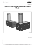
User Manual
COBRA 1X
6.3A-18003-A04
COBRA 1X
Lubrication Device for Moving Lubrication Points
Subject to modifications
6272b04
LINCOLN GmbH & Co. KG • Postfach 1263 • D-69183 Walldorf • Tel +49 (6227) 33-0 • Fax +49 (6227) 33-259
User Manual
COBRA 1X
6.3A-18003-A04
All rights reserved.
Any duplication of this User Manual, in its entirety or in part,
by whatever means is prohibited without the prior consent in
writing of Lincoln GmbH & CO. KG.
Subject to modifications without prior notification.
Phone: +49 (6227) 33-0
Fax: +49 (6227) 33-259
Subject to modifications
© 2004 by
LINCOLN GmbH & Co. KG
Postfach 1263
D-69183 Walldorf
Page 2 of 32
LINCOLN GmbH & Co. KG • Postfach 1263 • D-69183 Walldorf • Tel +49 (6227) 33-0 • Fax +49 (6227) 33-259
User Manual
COBRA 1X
6.3A-18003-A04
Table of Contents
Page
Page
Introduction .....................................................................
Explanation of Symbols Used ............................................
User’s Responsibility .........................................................
Environmental Protection ..................................................
Service ..............................................................................
4
4
4
4
4
Safety Instructions ..........................................................
Appropriate Use ................................................................
Applicable Lubricants ...................................................
Misuse ...............................................................................
Exclusion of Liability ....................................................
Regulations for Prevention of Accidents ............................
Disposal .............................................................................
General Safety Instructions ...............................................
Installation, Maintenance and Repair ................................
Operation ...........................................................................
5
5
5
5
5
5
5
5
5
6
Description .......................................................................
COBRA 1X ........................................................................
General ........................................................................
Features .......................................................................
Interface to equipment provided by the user .....................
Safety functions .................................................................
6
6
7
7
8
8
Planning and Layout .......................................................
Layout of the Holding Construction ...................................
Positioning .........................................................................
Positions ......................................................................
Lubricant pump .............................................................
Safety zone...................................................................
Lubricating devices ......................................................
Lubricant Supply ................................................................
Synchronization ...........................................................
Pump ...........................................................................
Feed Lines ...................................................................
9
9
9
9
9
9
9
9
9
9
9
Assembly and Start-up...................................................
Safety ...............................................................................
Preparation ......................................................................
Guidance of the conveyor belt ....................................
- Vertical guidance ......................................................
- Horizontal guidance .................................................
1. Preparation for adjustment .....................................
2. Vertical adjustment .................................................
3. Horizontal adjustment .............................................
4. Horizontal fine adjustment ......................................
- Adjust distance nozzle coupler – pick-up rollers ...
- Adjust pick-up stroke ............................................
5. Adjustment of swivelling distance ...........................
6. Adjustment of reverse travel speed ........................
7. Adjustment of output ..............................................
- Metering to zero ...................................................
- Adjustment ...........................................................
8. Adjustment of proximity switch ...............................
Start-up .............................................................................
10
10
10
10
10
10
11
11
11
12
12
12
13
13
14
14
14
14
14
Operating Method ...........................................................
Pneumatics and mechanics .............................................
Off-position .................................................................
Readiness for operation .............................................
Pick-up and lubrication phase .....................................
End of lubrication phase..............................................
Pull-back movement ...................................................
Lubricant supply ...............................................................
Metering procedure .....................................................
Lubrication procedure..................................................
Continuous operation of the COBRA 1X ..........................
Interval operation of the COBRA 1X ................................
Termination of readiness for operation .............................
15
15
15
16
17
18
19
20
20
21
21
21
21
Maintenance, Repair and Functional Test ...................
Maintenance ....................................................................
Repairs ............................................................................
Functional tests ................................................................
22
22
22
22
Troubleshooting.............................................................. 22
Technical Data................................................................. 25
Dimensions, assembly from the top ................................. 26
Dimensions, assembly from the bottom ........................... 27
Components and Kits..................................................... 28
Parts List .......................................................................... 29
Subject to modifications
Manufacturer’s Declaration ........................................... 31
Always keep this User Manual ready to hand
on the site where the COBRA 1X is in operation!
Page 3 of 32
LINCOLN GmbH & Co. KG • Postfach 1263 • D-69183 Walldorf • Tel +49 (6227) 33-0 • Fax +49 (6227) 33-259
User Manual
COBRA 1X
Introduction
6.3A-18003-A04
Explanation of Symbols Used
The following description standards are used in this manual:
Safety Instructions
Structure of safety instructions:
Pictogram
Signal word
Danger text
- Danger note
- How to avoid danger
The following pictograms are used in this manual and are
combined with the corresponding signal words:
1013A94
- ATTENTION
- CAUTION
- WARNING
4273a00
- ATTENTION
- CAUTION
- WARNING
6001a02
- NOTE
- IMPORTANT
The signal words give the seriousness of danger if the following text is not observed:
ATTENTION
CAUTION
WARNING
NOTE
IMPORTANT
refers to faults or damages on
machines.
refers to bad damages and possible injuries.
refers to possible dangerous injuries.
refers to improvements in handling
of systems.
refers to considerable disadvantages in handling of systems.
Example:
User's Responsibility
To ensure the safe operation of the unit, the user is responsible for the following:
1. The pump / system shall be operated only for the intended use (see next chapter "Safety Instructions") and
its design shall neither be modified nor transformed.
2. The pump / system shall be operated only if it is in a
proper functioning condition and if it is operated in accordance with the maintenance requirements.
3. The operating personnel must be familiar with this Owner
Manual and the safety instructions mentioned within and
observe these carefully.
The correct installation and connection of tubes and hoses, if
not specified by Lincoln GmbH & Co. KG, is the user's responsibility. Lincoln GmbH & Co. KG will gladly assist you
with any questions pertaining to the installation.
Environmental Protection
Waste (e.g. used oil, detergents, lubricants) must be disposed of in accordance with relevant environmental regulations.
Service
The personnel responsible for the handling of the pump /
system must be suitably qualified. If required, Lincoln GmbH
& Co. KG offers you full service in the form of advice, on-site
installation assistance, training, etc. We will be pleased to
inform you about our possibilities to support you purposefully.
In the event of inquiries pertaining to maintenance, repairs
and spare parts, we require model specific data to enable us
to clearly identify the components of your pump / system.
Therefore, always indicate the part, model and series number
of your pump / system.
Subject to modifications
1013A94
ATTENTION!
When making use of other than the original spare parts, serious damage may
affect your device.
Therefore, for the operation of your device
always use original spare parts made by
Lincoln GmbH & Co. KG.
Furthermore, you will find the following text symbols in this
manual:
Listing of applicable statements
- Subpoint of applicable statements
1. Determination of the number or sequence of contents
Procedural instruction
Page 4 of 32
LINCOLN GmbH & Co. KG • Postfach 1263 • D-69183 Walldorf • Tel +49 (6227) 33-0 • Fax +49 (6227) 33-259
User Manual
COBRA 1X
6.3A-18003-A04
Safety Instructions
Appropriate Use
The COBRA 1X lubrication device is exclusively designed for
the lubrication of moving lubrication points on rollers and
chain conveyors.
The appropriate use also refers to:
professional installation and repair works
regular visual controls and maintenance works
(depending on customized operation intervals)
disposal of used or contaminated lubricants as well as of
all parts that were in touch with lubricant according to the
legal regulations pertaining to environmental protection
safe operation by observing the technical data
General Safety Instructions
Lincoln lubrication devices COBRA 1X for moving lubrication points are designed state-of-the-art.
Incorrect use may result in bearing damage caused by
poor or excessive lubrication.
Unauthorized modification and alteration to the machine
are only allowed with the manufacturer’s or his contract
partner’s consent.
Use original Lincoln spare parts only or parts authorized
by Lincoln.
Warning directly fixed to the machine must always be
observed and must be kept in fully legible condition.
Applicable Lubricants
The lubrication device COBRA 1X is able to deliver greases
up to NLGI grade 2 or lubricating oils of at least 40 mm²/s
(cST) at 40 °C.
IMPORTANT
Make sure that the applied oils or greases
do not change their characteristics essentially due to age, pressure or temperature.
6001a02
Installation, Maintenance and Repair
The manufacturer recommends establishing a safety zone
around the operation area of the COBRA 1X.
Otherwise, the owner must secure the operation area with
protective devices against inadmissible access.
Maintenance, inspection, repair or installation work must
always be performed by authorized and instructed personnel who are familiar with the lubrication device.
On no account may work be carried out while the device
is in operation, but only in its off-position (see page 15).
In the case of exceptions:
Misuse
Any use of the COBRA 1X that is not expressly stated as
appropriate in this User Manual will be regarded as misuse. If
the COBRA 1X is used or operated in a different manner
other than the specified, any claim for warranty or liability will
be null and void.
CAUTION!
Risk of Crushing and Banging!
Make sure to observe all moving components when performing any work on the
COBRA 1X during operation.
Exclusion of Liability
6001a02
IMPORTANT
If personal injury or material damage occurs as a result of inappropriate operation,
e.g. if the safety instructions are ignored, or
resulting from an incorrect installation of
the COBRA 1X, no claims or legal actions
may be taken against Lincoln GmbH & Co.
KG.
1371a94
Fix the COBRA 1X at a suitable place (see pages 10 ff,
chapter “Assembly and Start-up“).
After completion of the assembly, maintenance or repair
work, reinstall all protective devices again.
Regulations for Prevention of Accidents
To prevent accidents, observe all city, state and federal
safety regulations of the country in which the product will be
used.
Disposal
Subject to modifications
Dispose of used or contaminated lubricants as well as of
parts that were in touch with lubricant according to the legal
regulations pertaining to environmental protection.
Page 5 of 32
LINCOLN GmbH & Co. KG • Postfach 1263 • D-69183 Walldorf • Tel +49 (6227) 33-0 • Fax +49 (6227) 33-259
User Manual
COBRA 1X
6.3A-18003-A04
Safety Instructions, continuation
Operation
CAUTION!
Risk of Crushing or Banging!
Always consider that the COBRA 1X may
move together with the conveyor belt when
ready for operation.
1371a94
6001a02
IMPORTANT
During operation the spring characteristic
of the COBRA 1X protects it against damage. Therefore, the lubrication device must
in no case be supported additionally.
Operation is allowed only under the following preconditions:
observe the maintenance instructions (see page 22)
technically proper condition of the lubrication device
all protective devices fixed (see page 8, chapter “Safety
functions“ and page 9, chapter “Positioning”)
use recommended or comparable lubricants (see page 5,
chapter “Applicable lubricants”)
follow the prescribed moving direction of the chain
operation only by authorized and instructed personnel
under observation of the instructions given in this User
Manual
within a complete system only, the commissioning of
which had been allowed under consideration of the respective directives
Description
COBRA 1X
6273b04
123-
COBRA 1X
Lubrication head (see Fig. 2)
Pick-up arm with air cylinder
Pressure gauge, lubricant pressure
456-
Slewing crank with pull-back spring
Safety notch
Base plate
78-
Slewing device
Mounting plate
Page 6 of 32
LINCOLN GmbH & Co. KG • Postfach 1263 • D-69183 Walldorf • Tel +49 (6227) 33-0 • Fax +49 (6227) 33-259
Subject to modifications
Fig. 1
User Manual
COBRA 1X
Description, continuation
6.3A-18003-A04
COBRA 1X, continuation
19-
6212b04
Fig. 2
Lubrication head
General
Features
- compact design
The COBRA 1X is a mechanically and pneumatically
operated lubrication device for the automatic lubrication of
moving rollers or swivel pins on transport chains.
- high rigidness
- reliable functionality
Applications:
- universally applicable on diverse roller or chain belts
- Power & Free belts
- adaptation of the required injecting pressure into the
roller or pin bearing of the transport chain
- Plate conveyors (mining industry)
- Coil conveyor belts (metallurgical industry),
- Crusher discharging belts and clinker transport
(cement industry)
- Circular conveyors, vehicle transport belts
(automobile industry)
On the transport chain a lubrication system normally consists of 2 COBRA lubrication devices, one in left-hand
version and one in right-hand version.
The COBRA 1X allows for the metered application of
lubricants into linearly moving lubrication points, even if
the roller distances vary.
The disconnection is effected via a 3-way air valve. The
valve can be activated as follows:
- mechanically (standard), manually
- chain pitch
- diameter of the chain rollers
The COBRA 1X is factory-adapted to the individual design
of the transport chain. Therefore, the geometry of the
chain must not change exceeding the admissible tolerances. It is determined by the following factors:
- dimensions of the chain rollers
- lubrication points on the transport chain
The metering quantity per stroke and lubrication point (0.2
to 2.0 cm³/ stroke) can be adjusted by means of the
measuring valve (see pos. 9).
As a protection against damages, the COBRA 1X has got
a safety notch (see fig. 1, pos. 5) as well as a slewing
notch (see fig. 1, pos. 7 and 8).
- electrically (option), remote disconnection possible
Subject to modifications
- pneumatically (option), remote disconnection possible
During the operation of the COBRA 1X variations in the
running speed of the transport chain are admissible to a
limited extent. Admissible variations in the running speed
depend on the following factors:
- average speed
- Beet transport belts (sugar industry).
Lubrication head with flush coupler (alternatively nozzle
for hydraulic lubrication fitting)
Pick-up arm and lubrication head bearing
Page 7 of 32
LINCOLN GmbH & Co. KG • Postfach 1263 • D-69183 Walldorf • Tel +49 (6227) 33-0 • Fax +49 (6227) 33-259
User Manual
COBRA 1X
Description, continuation
6.3A-18003-A04
Interfaces to the equipment provided by the user
COBRA 1X
left-hand version
right-hand version
6233b04
Fig. 3
Mechanics
working area
safety zone
holding construction
Lubricant supply
pump, pump pressure:
- 120 to 240 bar for grease
- 40 to 80 bar for oil
Pneumatics
maintenance unit
air pressure (5.5 to 6 bar)
shut-off valve
Controlling electronics
optionally via 3/2 way valve
Schematic of a lubrication system, view in direction of dispense
Safety Functions
Slewing notch (see page 6, fig. 1, pos. 7)
Safety notch (see page 6, fig. 1, pos. 5)
Preconditions
In case of unintentional pick-up of the pick-up rollers (see
page 10, fig. 4, pos. 2.1) by the transport chain
In case of a reverse movement of the transport chain
In case of a malfunction of the 5/2 way valve (see
page 13, fig. 7, pos. 13)
Function
The complete COBRA 1X is slewed out of the catchment
area of the transport chain.
As an option, this slewed position can be detected by a
proximity switch in order to provide an external control
with a signal.
Preconditions
In case the speed of the transport chain is too high
In case the actuating angle (page 13, fig. 7, pos. 4.3) has
been set wrongly.
Function
The safety notch engages into the slewed lubrication head
pick-up device and prevents it from slewing back into the
catchment area of the transport chain.
The 5/2-way valve (page 13, fig. 7, pos. 13) is thereby
actuated and drives the lubrication head pick-up device
(pos. 1 and 2) out of the catchment area of the transport
chain.
Subject to modifications
6001a02
IMPORTANT
Whenever one of the two safety functions has been applied, the COBRA 1X is out of operation.
Eliminate the cause for the activation of the safety function.
Bring the COBRA 1X back into the off position (see page 15).
Put the COBRA 1X into operation again (see page 14, chapter “Re-Start”).
Page 8 of 32
LINCOLN GmbH & Co. KG • Postfach 1263 • D-69183 Walldorf • Tel +49 (6227) 33-0 • Fax +49 (6227) 33-259
User Manual
COBRA 1X
6.3A-18003-A04
Planning and Layout
Layout of the holding construction
Prepare a holding construction with sufficient stability for
fixing four screws M10 (see page 11, fig. 5: hole pitches
270 x 70 mm), where the mounting plate can be attached
to (page 6, fig. 1, pos. 8).
The holding construction must provide a horizontal and
even rest for the mounting plate.
Keep a horizontal distance of 245 ± 5 mm (page 11, fig. 5)
from the lubrication fittings of the transport chain to the
hole pattern of the mounting plate.
During the vertical positioning, consider the different distances between the fixing versions from the top and those
from the bottom (see pages 26 and 27, fig. 23 and 24).
NOTE
6001a02
Customer services of Lincoln GmbH & Co.
KG are pleased to assist you in the
planning and layout of your automated
lubrication system (address on the rear
side of this User Manual).
Positioning
To determine the position of the COBRA 1X consider the
following factors:
Positions
Position with low degree of contamination
Position with high degree of contamination:
Install dust protection observing the maximum slewing
range (dimensions, see pages 26 and 27, fig. 23 and 24).
Lubricant pump
Lubricant Supply
Synchronization
Each COBRA 1X receives a separate feed line from the
pump.
The lubricant supply to two COBRA 1X lubrication devices
of a lubrication station is effected by dividing the feed line
into two supply lines of possibly equal lengths.
Pump
The output of the pump depends on the following factors:
the number of lubrication devices
the lubricant need per operating stroke
the stroke frequency:
stroke
Establishment of a safety zone (dimensions, see
pages 26 and 27, fig. 23 and 24).
Lubrication devices COBRA 1X
Feed Lines
The layout of the lubricant lines to provide the lubrication
devices with lubricant depends on:
the distance between the pump and the lubrication station
the viscosity of the lubricant
the required output
the minimum temperature expectation
IMPORTANT
6001a02
As the lubrication devices are to operate
simultaneously, there may occur a strong
short-term increase of lubricant
consumption.
Therefore, install a flexible hydraulic hose
on the lubricant inlet of each COBRA 1X.
Thanks to the flexibility of the hose walls,
an increased lubricant consumption can be
covered temporarily (accumulator effect).
NOTE
If mineral oils or fluid greases (NLGI 000
and 00) are used, differences in the line
lengths are insignificant.
Subject to modifications
Opposite positioning of two synchronized operating lubrication devices (example, see fig. 3) in order to avoid a
horizontal excursion of the conveyor belt.
Positioning of the lubrication devices:
Choose a running section of the transport belt where the
smallest horizontal (max. ±5 mm) and vertical variations
(max. ±1.5 mm) are expected.
If the variations of the transport belt are too big, the transport rollers must be guided (see page 10, chapter “Guidance of the conveyor belt“).
chain speed
chain pitch
Chain pitch: distance between two lubrication points on a
transport chain
Positioning of the lubricant pump:
As centrically as possible in order to achieve equal line
lengths to the lubrication devices.
Safety zone
frequency =
Page 9 of 32
LINCOLN GmbH & Co. KG • Postfach 1263 • D-69183 Walldorf • Tel +49 (6227) 33-0 • Fax +49 (6227) 33-259
User Manual
COBRA 1X
Assembly and Start-up
6.3A-18003-A04
Safety
CAUTION!
Risk of Crushing or Banging!
Carry out any preparation and assembly
works only with the transport belt switched
off.
1013A94
1013A94
During the test run with disassembled
protective devices, make sure to particularly observe all automated moving procedures in the catchment and slewing area of
the COBRA 1X.
Attach the respective protective devices
upon completion of assembly and start-up.
Preparation
Guidance of the conveyor belt
Vertical guidance (Pos. A):
The COBRA 1X can compensate a vertical excursion of the
chain rollers (pos. C) of ±1.5 mm.
In case of bigger excursions, mount vertical guidances
(pos. A) in the catchment area of the pick-up rollers
(pos. 2.1).
6001a02
NOTE
The vertical guidances (pos. A) must not
limit the moving process of the pick-up
rollers(pos. 2.1) during the pick-up and
lubrication phase (see page 17).
The distance between the vertical guidances (pos. A) must be big enough so that
the chain rollers (pos. C) will not stick between them during their passage.
If necessary, spare the vertical guidance (pos. A) of the
conveyor chain in the catchment area (min. 180 mm) of
the pick-up rollers (pos. 2.1).
Horizontal guidance (pos. B):
The COBRA 1X can compensate a horizontal excursion of
the chain rollers (pos. C) of ±5 mm.
In case of bigger excursions, mount horizontal guidances
(pos. B) in the catchment area of the pick-up rollers
(pos. 2.1).
6235b03
Guidance of the conveyor belt
Pick-up rollers
Pick-up rollers, waiting position
Pick-up rollers, backstroke position
Vertical guidance
Horizontal guidance
Chain rollers of the transport chain
CAUTION!
If there are no guidances for the chain
rollers, some rollers may suffer poor lubrication and the lubrication head may be
damaged.
1013A94
Subject to modifications
Fig. 4
2.1 III ABC-
Page 10 of 32
LINCOLN GmbH & Co. KG • Postfach 1263 • D-69183 Walldorf • Tel +49 (6227) 33-0 • Fax +49 (6227) 33-259
User Manual
COBRA 1X
Assembly and Start-up, continuation
6.3A-18003-A04
Assembly, continuation
6232b04
Fig. 5
Assembly of the COBRA 1X
1.1 - Lubrication head, nozzle for hydraulic
lube fitting (off position)
ALubrication fitting of the transport chain
7.1 - Slewing plate
8-
Mounting plate
B-
C-
Oblong holes of the slewing plate
Chain roller
1. Preparation for adjustment
Subject to modifications
Loosen the fastening nuts (see page 28, fig. 25, pos. 4.5)
on the threaded rods M 20 (pos. 4.4).
Separate the mounting and slewing plate (fig. 5, pos. 7.1
and 8) from the COBRA 1X.
Fix the mounting plate (pos. 8) with four fastening screws
M10 to the holding construction (see page 9, chapter
“Layout of the holding construction”).
Make sure that for execution of item 1. to 3. the COBRA
1X is in off position (see page 15).
Make sure that the mounting plate is supported horizontally and evenly by the holding construction.
Tighten the four fastening screws M10 upon the positioning of the mounting plate:
M10 … 35 Nm
2. Vertical adjustment
Put the threaded rod M20 (see page 28, pos. 4.4) of the
COBRA 1X back into the oblong holes (pos. C) of the
slewing plate (pos. 7.1).
Tighten the fastening screws M20 (pos. 4.5) slightly.
Place the nozzle coupler (pos. 1.1) respectively the axis of
the lubrication head (pos. 1) horizontally to the height of
the lubrication fitting (pos. A). To do so, use the thread
pitch of the threaded rods M20 (pos. 4.4) in combination
with the fastening nuts M20 (pos. 4.5).
Make sure that the axis of the lubrication head is parallel
to and at the same height as the axis of the lubrication fitting. This is valid for the complete moving area of the
COBRA 1X.
3. Horizontal adjustment
Move the threaded rods M20 (see page 28, pos. 4.4)
along the oblong holes (pos. C) until you achieve a distance of 36,5± 2,5 mm between the nozzle coupler and the
± 2,5
lubrication fitting (see fig. 5). The distance 36,5
mm is
the way that has to be done between the nozzle coupler in
off position and the pressure contact to the lubrication fitting.
IMPORTANT
Even in case of the maximum horizontal
roller variation, the distance must not be
more than 39 mm.
6001a02
Tighten the fastening nuts after completion of the positioning:
M20 … 290 Nm
Check all adjustments after tightening all screws.
If necessary, carry out the corrections.
Page 11 of 32
LINCOLN GmbH & Co. KG • Postfach 1263 • D-69183 Walldorf • Tel +49 (6227) 33-0 • Fax +49 (6227) 33-259
User Manual
COBRA 1X
Assembly and Start-up, continuation
6.3A-18003-A04
Assembly, continuation
6283b04
Fig. 6
Horizontal fine adjustment
4. Horizontal fine adjustment
4273a00
CAUTION!
Before connecting the lubrication devices
make sure to disconnect the system from
the power supply.
Only qualified electricians should proceed
with assembly and installation of electrical
equipment. Observe all pertinent safety
regulations and standards.
Adjust pick-up stroke
In the operating status “Waiting position“ the pick-up rollers are to move 7 to 15 mm into the catchment area of the
chain rollers (feeding depth 10 +-53 mm, see page 26 and
27, fig. 23 and 24).
6001a02
Make sure that the COBRA 1X is in waiting position (see
page 17).
IMPORTANT
Observe the minimum measure of 7 mm
for all horizontal chain roller and transport
chain variations.
The measure of 15 mm may be exceeded
under the following conditions only:
Adjust distance nozzle coupler – pick-up rollers
For the fine adjustment loosen the fastening screws
(pos. A) on the oblong holes of the pick-up arm (see
pos. 2.6).
Move the transport chain to that extent that one chain
roller stops at the pick-up rollers (pos. 2.1, see page 18,
fig. 14).
Variegate the distance between the pick-up rollers
(pos. 2.1) and the lubrication head (pos. 1) along the oblong holes (pos. A).
Position the nozzle coupler (pos. 1.1) exactly to a lubrication point whereby the pick-up rollers (pos. 2.1) must in no
case loose the contact to the chain roller.
Retighten the fastening screws (pos. A) after completion
of the positioning:
M 10 … 35 Nm
Check all adjustments after tightening all screws.
if the pick-up rollers (pos. 2.1) do not
run against stationary walls
if the pick-up rollers (pos. 2.1) do not
push the chain roller off the nozzle
coupler (pos. 1.1).
Loosen the nuts (see fig. 7, pos. C) on the pick-up guide
rod (pos. 2.4).
Move the pick-up stop (pos. 2.5) to the end of the pick-up
guide rod (pos. 2.4) in order to feed the pick-up rollers into
the catchment area of the chain rollers. Otherwise, move
the pick-up stop further on the pick-up guide rod.
NOTE
It is possible to move the stop up to 15 mm
on the guide rod. This corresponds to a
pick-up stroke of 60 to 75 mm.
6001a02
Page 12 of 32
LINCOLN GmbH & Co. KG • Postfach 1263 • D-69183 Walldorf • Tel +49 (6227) 33-0 • Fax +49 (6227) 33-259
Subject to modifications
Provide the air supply for the COBRA 1X.
If necessary, carry out the installation for electrically operated 3/2-way valves.
User Manual
COBRA 1X
Assembly and Start-up, continuation
6.3A-18003-A04
Assembly, continuation
6284b04
Fig. 7
Adjustment of swiveling distance and reverse travel speed
5. Adjustment of swiveling distance
6. Adjustment of reverse travel speed
Modify the reverse travel speed during the pull-back
movement (see page 18) by screwing the throttle screw
on the check valve in or out (pos. 15).
The actuating angle (pos. 4.3) stops the movement of the
slewing cranks (pos. 4.1) at the end of the lubrication
process. It actuates the 5/2-way valve (pos. 13).
Loosen the two screws (M 6) of the actuating angle
(pos. 4.3).
Modification of the swiveling distance
Shortening: (reduce angle α) to increase the operating
frequency and at the same time reduce the lubrication
time
Elongation: (enlarge angle α) to prolong the lubrication
time
Move/ turn the actuating angle as follows:
Reduce reverse travel speed
by screwing-in the throttle screw
during low chain speed
to avoid the contact of the pick-up rollers (pos. 2.1) with
an already lubricated chain roller during the pull-back
movement
to reduce the shock load at the end of the pull-back
movement
COBRA 1X
Subject to modifications
Swiveling distance
Shortening
Elongation
Right-hand
version
clockwise
counterclockwise
Left-hand
version
counterclockwise
clockwise
Increase reverse travel speed
by screwing-out the throttle screw
to increase the lubrication frequency
Page 13 of 32
LINCOLN GmbH & Co. KG • Postfach 1263 • D-69183 Walldorf • Tel +49 (6227) 33-0 • Fax +49 (6227) 33-259
User Manual
COBRA 1X
Assembly and Start-up, continuation
6.3A-18003-A04
Assembly, continuation
7. Adjustment of output
8. Adjustment of proximity switch
Make sure that the COBRA 1X is in off position (see page
15).
The slewing plate is fastened to the mounting plate by
screws and locked on the pressure piece (see page 28,
pos. 7.2).
Screw the proximity switch (pos. 7.3) into the threaded
bore M12 x 1 of the mounting plate.
The screwing depth is 0.5 mm less than the thickness of
the mounting plate (10 mm). Exceeding this screwing
depth will destroy the proximity switch during the slewing
function.
Make sure that the COBRA 1X is in off position (see
page 15).
Start-up
Fig. 8
Metering via lubrication head
Metering to zero
(broken-line representation of the metering screw pos. 1.10)
Tighten the metering screw (pos. 1.10) up to the mechanical stop of the metering ram (pos. 1.9) and of the
supply piston (pos. 1.6).
Adjustment
2)
Turn the thread revolutions indicated in the following
chart back in order to adjust the corresponding output
1)
(with the maximum output being S = 5.5 mm ).
Keep to the recommended range of adjustment (S ≤ 23.5
mm), as otherwise the inaccuracy of the output per stroke
increases (minimum output 0.2 cm³/ stroke).
6278b04
25.5
23.5
20.5
15.5
10.5
0
2
5
10
15
Metering to
zero
Fig. 9
1)
2)
5.5 mm
20 n
1)
2)
Range of adjustment
Output diagram
Depth gauge S in mm
Number of thread revolutions (n) of the metering screw
(pos.1.10) as of the metering to zero
Fix the adjustment of the metering screw (pos. 1.10) by
means of a fastening screw (pos. 1.11).
Observe the note regarding the lubrication procedure (see
page 21).
Remove lines already connected.
Clean, fill and mount the lines.
Set the lubricant pressure:
- for grease from 120 to 240 bar
- for oil from 40 to 80 bar
Check the adjustments of chapters 1, 2 and 3 (see
page 11):
- when the transport chain is standing
- when the 3/2-way valve is not actuated (see
page 15, pos. 14)
Check the adjustments of chapter 4 (see page 12):
- when the air supply is connected
- when the 3/2-way valve is actuated (pos. 14)
- when having contact between the chain rollers and the
pick-up rollers
Check the adjustments of chapters 5 and 6 (see page 13):
- during the moving procedure of the COBRA 1X
- if possible when the lubricant supply is shut-off
- when the air supply is connected
- when the 3/2-way valve is actuated (pos. 14)
- applying the planned transport direction and speed of
the running transport chain.
Check the adjustment of the output according to chapter 7
in off position.
Activate the lubricant supply
- Switch the pump on
- Open the lubricant line
Check the lubrication procedure several times with the
COBRA 1X in operation (see page 22, chapter “Functional
test“).
Adapt the pump pressure to the required lubricant injecting pressure into the roller respectively bold bearings of
the transport chain.
Reconnection
If necessary, eliminate the cause for the activation of a
safety function (see page 8) before the reconnection.
Also consider the chapter “Troubleshooting“ (see pages
22 ff).
Put the COBRA 1X into the operating status “Off position”
first, then into “Waiting position” (see pages 15 and 16).
Page 14 of 32
LINCOLN GmbH & Co. KG • Postfach 1263 • D-69183 Walldorf • Tel +49 (6227) 33-0 • Fax +49 (6227) 33-259
Subject to modifications
6279b04
User Manual
COBRA 1X
6.3A-18003-A04
Operating Method
Pneumatics and Mechanics
Off position
In the off position the COBRA 1X is out of operation.
Characteristics of the off position
The valves (pos. 13 and 14) are inoperative (valve position, see fig. 11). The compression springs (pos. 1.2 and
2.3) maintain the lubrication head (pos. 1) and the pick-up
arm (pos. 2) in off position.
The pick-up rollers (pos. 2.1) are positioned outside of the
catchment area of the chain rollers (pos. A).
6001a02
NOTE
If the COBRA 1X is not pressurized, the
compression springs (pos. 1.2 and 2.3)
maintain the lubrication head (pos. 1) and
the pick-up arm (pos. 2) in off position.
The lubricant supply pump is switched off.
6230b03
Fig. 10
COBRA 1X in off position
1.1 1.2 2.1 2.2 2.3 13 14 6274b04
Pneumatic wiring diagram in off position
A-
Subject to modifications
Fig. 11
nozzle coupler
compression spring for lubrication head
pick-up rollers
cylinder
Compression spring for pick-up arm
5/2-way valve, mechanically operated
3/2-way valve, mechanically operated (option: pneumatical,
electrical)
chain rollers
Page 15 of 32
LINCOLN GmbH & Co. KG • Postfach 1263 • D-69183 Walldorf • Tel +49 (6227) 33-0 • Fax +49 (6227) 33-259
User Manual
COBRA 1X
Operating Method, continuation
6.3A-18003-A04
Pneumatics and Mechanics, continuation
Waiting position
In the waiting position the COBRA 1X is ready for operation.
Characteristics of the waiting position
The 3/2-way valve (pos. 14) is operative.
The 5/2-way valve (pos. 13) is operative.
(Valve position see fig. 13).
The cylinder (pos. 2.2) drives the lubrication head (pos. 1)
and the pick-up arm (pos. 2) into the direction of the
transport chain.
The pick-up rollers (pos. 2.1) are positioned in the catchment area of the chain rollers (pos. A).
6001a02
NOTE
The extracting speed of the lubrication
head (pos. 1) and the pick-up arm (pos. 2)
can be adjusted on the throttle check valve
(pos. 15).
6225b03
Fig. 12
COBRA 1X in waiting position
1.1 2.1 2.2 13 14 6275b04
Pneumatical wiring diagram in waiting position
15 A-
Subject to modifications
Fig. 13
nozzle coupler
pick-up rollers
cylinder
5/2-way valve, mechanically operated
3/2-way valve, mechanically operated (option: pneumatical,
electrical)
throttle check valve
chain rollers
Page 16 of 32
LINCOLN GmbH & Co. KG • Postfach 1263 • D-69183 Walldorf • Tel +49 (6227) 33-0 • Fax +49 (6227) 33-259
User Manual
COBRA 1X
Operating Method, continuation
6.3A-18003-A04
Pneumatics and Mechanics, continuation
Pick-up and Lubrication Phase
During the pick-up and lubrication phase the COBRA 1X is in
contact with the transport chain.
Characteristics of the pick-up phase
The valve position (pos. 13 and 14) remains like in the
waiting position (see page 16).
A chain roller (pos. A) reaches the pick-up rollers (pos.
2.1) and moves the complete slewing crank (pos. 4.1 and
4.2 with pos. 1 and 2) in the running direction of the transport chain.
The slewing movement of the slewing cranks (pos. 4.1)
increases angle α during the pick-up phase. As a consequence the pull-back spring is bended and nozzle coupler
as well as pick-up rollers are moved towards the transport
chain.
1.1 2.1 2.2 4.1 4.2 13 14 A-
flush coupler
pick-up rollers
cylinders
slewing cranks
pull-back spring
5/2-way valve
3/2-way valve, mechanically operated (options: pneumatically
or electrically operated)
chain rollers
6226b03
Fig. 14
During the lubrication phase the COBRA 1X dispenses lubricant to the lubrication point.
Characteristics of the lubrication phase
COBRA 1X in pick-up phase
The valve position (pos. 13 and 14) remains like in the
waiting position (see page 16).
The pull-back spring (pos. 4.2) is still bended.
Nozzle coupler (pos. 1.1) and pick-up roller (pos. 2.1)
move towards the transport chain.
The nozzle coupler is pressed onto the lubrication fitting of
the chain roller (pos. A).
By doing so the lubrication head rod (pos. 1.3) is pressed
into the lubrication head housing (pos. 1.4) and triggers
the lubrication stroke (see page 21, chapter “Lubrication
procedure“).
Subject to modifications
6001a02
6227b03
Fig. 15
COBRA 1X in the lubrication phase
1.1 1.3 1.4 2.1 2.8 4.1 4.2 13 14 -
NOTE
The function of the compression springs
(pos. 2.8) prevents the pick-up rollers (pos.
2.1) from being damaged, even in case of
a maximum approach to the chain rollers
(pos. A).
flush coupler
lubrication head rod
lubrication head housing
pick-up rollers
compression springs of the pick-up rollers
slewing cranks
pull-back spring
5/2-way valve
3/2-way valve, mechanically operated (options: pneumatically
or electrically operated)
Page 17 of 32
LINCOLN GmbH & Co. KG • Postfach 1263 • D-69183 Walldorf • Tel +49 (6227) 33-0 • Fax +49 (6227) 33-259
User Manual
COBRA 1X
Operating Method, continuation
6.3A-18003-A04
Pneumatics and Mechanics, continuation
End of the lubrication phase
At the end of the lubrication phase the COBRA 1x is separated from the transport chain.
Characteristics at the end of the lubrication phase
The 3/2-way valve (pos. 14) is actuated.
The 5/2-way valve (pos. 13) is actuated by a mechanical
contact on the actuating angle (pos. 4.3, valve position
see fig. 17).
NOTE
6001a02
The angle α has reached its maximum
value as soon as the 5/2-way valve (pos.
13) is actuated. The actuation of the 5/2way valve is effected by adjusting the actuating angle (pos. 4.3) (see page 12,
chapter “Adjustment of the slewing distance“).
Afterwards the compression springs (pos. 1.2 and 2.3)
remove the lubrication head (pos. 1) and the pick-up arm
(pos. 2) from the transport chain.
6228b03
COBRA 1X at the end of the lubrication procedure
1.1 2.1 2.2 4.1 4.2 4.3 13 14 6276b04
Fig. 17
Pneumatic wiring diagram at the end of the lubrication
procedure
A-
nozzle coupler
pick-up rollers
cylinder
slewing cranks
pull-back spring
actuating angle
5/2-way valve, mechanically operated
3/2-way valve, mechanically operated (options: pneumatically
or electrically operated)
chain rollers
Page 18 of 32
LINCOLN GmbH & Co. KG • Postfach 1263 • D-69183 Walldorf • Tel +49 (6227) 33-0 • Fax +49 (6227) 33-259
Subject to modifications
Fig. 16
User Manual
COBRA 1X
Operating Method, continuation
6.3A-18003-A04
Pneumatics and Mechanics, continuation
Pull-back movement
During the pull-back movement the COBRA 1X slews back
into the waiting position.
Characteristics of the pull-back movement
The 3/2-way valve (pos. 14) is actuated.
The 5/2-way valve (pos. 13) looses the mechanical contact on the actuating angle (pos. 4.3; valve position, see
fig. 19)
6001a02
NOTE
The extracting speed of the lubrication
head (pos. 1) and of the pick-up arm
(pos. 2) can be adjusted on the throttle
check valve (pos. 15).
The bended pull-back spring (pos. 4.2) pulls the slewing
cranks (pos. 4.1) back into the waiting position (see page
15).
The cylinder (pos. 2.2) moves the lubrication head
(pos. 1) and the pick-up arm (pos. 2) towards the transport chain.
The pick-up rollers (pos. 2.1) move into the catchment
area of the chain rollers (pos. A) again.
6229b03
Fig. 18
COBRA 1X at the end of the pull-back movement
1.1 2.1 2.2 4.1 4.2 4.3 13 14 6277b04
Pneumatic wiring diagram at the end of the pull-back
movement
15 A-
Subject to modifications
Fig. 19
nozzle coupler
pick-up rollers
cylinder
slewing cranks
pull-back spring
actuating angle
5/2-way valve, mechanically operated
3/2-way valve, mechanically operated (options: pneumatically
or electrically operated)
throttle check valve
chain rollers
Page 19 of 32
LINCOLN GmbH & Co. KG • Postfach 1263 • D-69183 Walldorf • Tel +49 (6227) 33-0 • Fax +49 (6227) 33-259
User Manual
COBRA 1X
Operating Method, continuation
6.3A-18003-A04
Lubricant Supply
6215b04
Fig. 20
Lubrication head during metering procedure
1.1 - nozzle coupler (here: flush coupler, option: coupler
for hydraulic lubrication fitting)
1.3 - lubrication head rod
1.5 - control piston
1.6 - supply piston
1.7 - compression spring for control piston
1.8 - compression spring for lubrication head rod
1.9 - control pin
1.10 - metering screw
1.11 - fastening screw
Alubrication fitting
Bmetering chamber
Metering procedure
6216b03
Fig. 21
Metering procedure
Lubricant lines:
- white: without pressure
- light-grey: pump pressure
Subject to modifications
When the lubricant pump (pos. P) is switched on, during
the metering procedure the COBRA 1X passes the following operating states:
- End of the lubrication procedure (see page 18)
- Pull-back movement (see page 19)
- Waiting position (see page 16)
- Start of the pick-up phase and lubrication phase (see
page 17)
The lubrication head rod (pos. 1.3) and the control piston
(pos. 1.5) are maintained at their respective end positions
by compression springs (pos. 1.7 and 1.8).
The control piston (pos. 1.5) releases the feed line to the
metering chamber (pos. B) on the left side of the supply
piston (pos. 1.6) so that the pump pressure moves the
supply piston (pos. 1.6) up to the metering pin (pos. 1.9).
Turn the metering screw (pos. 1.10) in or out to adjust
the output per lubrication stroke from 0.2 to 2.0 cm³.
Fix the position of the metering screw (pos. 1.10) with the
fastening screw (pos. 1.11).
Page 20 of 32
LINCOLN GmbH & Co. KG • Postfach 1263 • D-69183 Walldorf • Tel +49 (6227) 33-0 • Fax +49 (6227) 33-259
User Manual
COBRA 1X
Operating Method, continuation
6.3A-18003-A04
Permanent operation of the COBRA 1X
Lubricant Supply, continuation
(Electrical control not required)
Lubrication procedure
During the comprehensive lubrication cycle of the transport
chain the COBRA 1X changes exclusively between the following operating states:
1. waiting position (see page 16)
2. pick-up phase and lubrication phase (see page 17)
3. end of lubrication phase (see page 18)
4. pull-back movement (see page 19)
5. waiting position (see page 16)
6. pick-up phase and lubrication phase, etc.
Interval operation of the COBRA 1X
(Electrical control required)
6217b03
Fig. 22
Lubrication phase
1.1 - flush coupler
1.5 - control piston
1.7 - compression spring for
control piston
1.9 - control pin
1.11 - fastening screw
Alubrication fitting
Lubricant lines:
Bmetering chamber
- white: without pressure
- light-grey: pump pressure
- dark-grey: supply pressure
At the end of the pick-up and lubrication phase (see
pages 17 and 18) the COBRA 1X is ready for lubrication.
The nozzle coupler (pos. 1.1) is pressed onto the lubrication fitting (pos. A) of a chain roller and moves the control
piston (pos. 1.5) back.
Thus the lubricant line towards the metering chamber is
closed and the supply line towards the nozzle coupler
(pos. 1) is opened.
The output capacity of the pump (pos. P) presses the
premetered output quantity to the nozzle coupler (pos.
1.1.) via the supply piston (pos. 1.6).
At the beginning of the pull-back movement the nozzle
coupler (pos. 1.1) frees itself from the lubrication fitting of
the chain roller.
The compression springs (pos. 1.6 and 1.7) press the
lubrication head rod (pos. 1.3) and control piston (pos.
1.5) back into their end positions.
Then another metering is initiated.
6001a02
Subject to modifications
1.3 - lubrication head rod
1.6 - supply piston
1.8 - compression spring for
lubrication head rod
1.10 - metering screw
If the supply speed of the transport chain exceeds the fastest
lubrication cycle sequence of the COBRA 1X, only every
second or third chain roller must be lubricated. This results in
the following cycle of operating states:
1. off position (see page 15)
2. waiting position (see page 16)
3. pick-up phase and lubrication phase (see page 17)
4. end of lubrication phase (see page 18)
5. pull-back movement (see page 19)
6. waiting position (see page 16)
7. off position (see page 15)
8. waiting position, etc.
The duration of the off positions must be actuated by means
of an external control via the 3/2-way valve (pos. 14).
Depending on the adjustment of the actuating angle (see
page 13, fig. 7, pos. 4.3), the throttle check valve (pos. 15)
and the control sensory mechanism every sixth operating
state (6. = waiting position) can be suppressed.
Termination of readiness for operation
When switching off the air supply via the 3/2-way valve
the COBRA 1X changes into the off position (see page
15).
Thereby the compression springs (pos. 1.2 and 2.3) remove the lubrication head (pos. 1) and the pick-up arm
from the transport chain.
The pick-up rollers (see page 19, pos. 2.1) are out of the
catchment area of the chain rollers (see page 19, fig. 18,
pos. A).
IMPORTANT
The lubrication procedure is incomplete if
the supply piston (pos. 1.6) could not reach
its final position (see control pin, page 14,
fig. 8, pos. 1.9) in time.
Reduce the output (see page 14) so
that the supply stroke can be completed within the lubrication phase (see
page 17).
Shorten the lubrication pauses of the
transport chain accordingly.
Page 21 of 32
LINCOLN GmbH & Co. KG • Postfach 1263 • D-69183 Walldorf • Tel +49 (6227) 33-0 • Fax +49 (6227) 33-259
User Manual
COBRA 1X
Maintenance, Repair and Functional Tests
6.3A-18003-A04
Maintenance
NOTE
6001a02
Whenever work is performed on the centralized lubrication system, special attention should be paid to absolute cleanliness.
Dirt will cause failure of the system.
IMPORTANT
To clean the system, use petroleum spirit
or petroleum. Do not use Tri, Per or similar
solvents or polar or organic solvents such
as alcohol, methanol, acetone, etc.
Repairs
Protect the COBRA 1X against serious contamination,
excessive influence of liquids or humidity and falling objects.
Lubricate the sliding surfaces of the COBRA 1X at the
latest after 50,000 lubrication strokes or at least five times
a year.
- Sliding surfaces are found:
on the lubrication head (page 29, pos. 1)
on the pick-up arm (pos. 2)
on the bearings of the slewing cranks (pos. 4.1)
- For this purpose use commercial machine oil for sliding
surfaces.
- Differentiate between the friction pairings steel-steel
and steel-plastic.
Functional Test
For repair works on the lubrication device use only original
Lincoln spare parts.
In case of warranty or for bigger repairs, send the lubrication device to the manufacturer.
Contact:
See rear side of this User Manual.
When lubrication is active (see pages 15 to 20):
During the pull-back movement (see page 19) a short
drop in pressure can be stated on the pressure gauge of
the lubricant supply.
The functioning of the COBRA X1 can be controlled via
the movement of the metering pin (see page 20, pos. 1.9).
Check whether the nozzle coupler (see page 20, pos.
1.1.) contacts the lubrication fitting centrically. Make sure
that no lubricant leaks out during the lubrication phase
(see page 17).
Carry out a spot check to verify the proper condition of the
lubrication fittings on the transport chain.
Troubleshooting
No or insufficient lubricant supply
Cause:
Remedy:
Metering of lubricant is set to zero or too little supply value Verify adjustment of output and correct if necessary (see
page 14, item 7).
Lubricant inlet pressure too low (see pages 26 and 27, fig. Check the function of the pump; if necessary, increase
23 and 24, pos. 3)
pump pressure (see page 25, chapter “Technical Data”).
Distance from the lubrication head (pos. 1) to the lubrication Control mounting position of the COBRA 1X (see page 11
fitting on the chain roller is too big
and 12, item 1 to 4).
Slewing distance of the slewing cranks (pos. 4.1) is too
short
The pick-up roller pushes (pos. 2.1) the chain roller off the Check adjustment of pick-up stroke and correct if necessary
lubrication head (pos. 1)
(see page 12, chapter “Adjust pick-up stroke“).
Verify adjustments and correct if necessary (see page 13,
item 5).
(Indications of positions without reference to figure or page refer to chapter “Components and Kits”, see page 28 ff)
Page 22 of 32
LINCOLN GmbH & Co. KG • Postfach 1263 • D-69183 Walldorf • Tel +49 (6227) 33-0 • Fax +49 (6227) 33-259
Subject to modifications
Fault:
User Manual
COBRA 1X
Troubleshooting, continuation
Fault:
Lubrication head (pos. 1) and pick-up arm (pos. 2) do not move into waiting position (see page 15)
Cause:
Remedy:
Check air connections, and for the version with electrically
operated 3/2-way valve (pos. 14) also check the electrical
connections.
3/2-way valve (pos. 14) does not actuate
Check the functioning of the valve and replace 3/2-way
valve (pos. 14) if necessary.
For the version with drive via chain sensor: Check the
functioning of the proximity switch “chain sensor” and its
electrical connections to the 3/2-way valve (pos. 14).
5/2-way valve (pos. 13) does not switch to waiting position Verify mounting position of the 5/2-way valve (pos. 13) and
the actuating angle (pos. 4.3) and correct if necessary
(page 13, item 5).
Check the functioning of the valve and replace 5/2-way
valve (pos. 13) if necessary.
Throttle check valve (pos. 15) clogged
Verify the functioning of the throttle check valve (pos. 15)
by unscrewing the throttle screw; replace throttle check
valve if necessary.
Cylinder (pos. 2.2) does not extract
Check the functioning of the cylinder, air pressure and air
connections; if necessary replace cylinder (pos. 2.2).
Mechanical connection interrupted between cylinder (pos. Verify mechanical connections.
2.2) and lubrication head (pos. 1) and/ or pick-up arm
(pos. 2)
Fault:
Pick-up rollers (pos. 2.1) do not go deep enough or too deep into the catchment area of the chain rollers
Cause:
Remedy:
Wrong COBRA 1X mounting position
Check COBRA 1X mounting position and correct if necessary (see pages 11 and 12, items 1 to 4).
Pick-up stroke initiated by the cylinder (pos. 2.2) is wrong
Verify adjustment of pick-up stroke (see page 12, chapter
“Adjust pick-up stroke”).
Fault:
Nozzle coupler (pos. 1.1) does not hit the lubrication fitting of the chain roller
Cause:
Subject to modifications
6.3A-18003-A04
Remedy
Wrong COBRA 1X mounting position
Check the COBRA 1X mounting position and correct if necessary (see pages 11 and 12, items 1 to 4).
Wrong distance between pick-up rollers (pos. 2.1) and
lubrication head (pos. 1)
Correct distance by adjusting the pick-up arm (pos. 2.6; see
page 12, “Adjust distance nozzle coupler – pick-up rollers).
Lubrication fitting is not positioned in the center of the chain Make sure to adjust the chain roller accordingly.
roller
Chain rollers have different diameters
The transport chain must be equipped with chain rollers of
equal diameters by the user of the system.
(Indications of positions without reference to figure or page refer to chapter “Components and Kits”, see page 28 ff)
Page 23 of 32
LINCOLN GmbH & Co. KG • Postfach 1263 • D-69183 Walldorf • Tel +49 (6227) 33-0 • Fax +49 (6227) 33-259
User Manual
COBRA 1X
Troubleshooting, continuation
6.3A-18003-A04
Fault: Lubricant leaks out between the nozzle coupler (pos. 1.1) on the lubrication head (pos. 1) and the lubrication
fitting on the chain roller
Cause:
Remedy:
The nozzle coupler (pos. 1.1) does not hit the lubrication
fitting of the chain roller in its center
Pressure force of the nozzle coupler (pos. 1.1) to the lubri- Check inlet pressure and correct if necessary (see page 25,
chapter “Technical Data“).
cation fitting of the chain roller is too little
Lubrication fitting of the chain roller is damaged and/ or
clogged
Fault:
roller
The user must ensure to bring the lubrication fittings into full
working order.
Pick-up rollers (pos. 2.1) don’t go into the catchment area of the transport chain right before each chain
Cause:
See fault “Nozzle coupler (pos. 1.1) does not hit the lubrication fitting of the chain roller“.
Remedy:
Moving procedure too slow
Verify inlet pressure and correct if necessary (see page 25,
chapter “Technical Data”).
Increase reverse travel speed (see page 13, item 6).
Reduce swiveling distance of the slewing cranks (pos. 4.1;
see page 13, item 5).
Slewing cranks (pos. 4.1) go into the safety notch (pos. 5)
Cause:
Remedy:
Swiveling distance of the slewing cranks (pos. 4.1) is too
big
Fault:
COBRA swivels against the proposed supply direction of the transport chain (see pos. 7 and 8)
Cause:
Remedy:
Wrong chain running direction
Fault:
Remedy:
Slewing cranks (pos. 4.1) engaged in the safety notch
(pos. 5)
5/2-way valve (pos. 13) does not actuate
Fault:
The user of the system must ensure the correct chain running direction.
COBRA swivels in the proposed supply direction of the transport chain (see pos. 7 and 8)
Cause:
Reduce swiveling distance of the slewing cranks (pos. 4.1;
see page 13, item 5).
Check the actuating angle (pos. 4.3) as well as position and
function of the 5/2-way valve (pos. 13): if the slewing cranks
(pos. 4.1) are positioned in the safety notch (pos. 5), the
5/2-way valve (pos. 13) must actuate reliably.
Lubricant leaks from the relief valve (pos. 16)
Cause:
Remedy:
Pump pressure is too high
Adjust pump pressure (see page 24, chapter “Technical
Data”).
Relief valve (pos. 16) defective or contaminated
Replace relief valve (pos. 16).
(Indications of positions without reference to figure or page refer to chapter “Components and Kits”, see page 28 ff)
Page 24 of 32
LINCOLN GmbH & Co. KG • Postfach 1263 • D-69183 Walldorf • Tel +49 (6227) 33-0 • Fax +49 (6227) 33-259
Subject to modifications
Fault:
User Manual
COBRA 1X
6.3A-18003-A04
Technical Data
COBRA 1X
NOTE
An operation of the COBRA 1X is admissible only with oiled air.
6001a02
Air connection ................................................................ G 3/8
Lubricant connection ..................................................... G 3/8
Inlet air pressure ................................................... 5.5 to 6 bar
Inlet lubricant pressure:
- for grease ...................................................... 120 to 240 bar
- for oil ................................................................. 40 to 80 bar
Control stroke of the lubrication head rod (pos. 1.3) into the
lubrication head housing (pos. 1.4) ............................... 8 mm
Output 1) ..................... infinitely variable 0.2 to 2.0 cm³/stroke
1)
Lubricant
- Grease ......................................................... NLGI grade 2
- Lubrication oil ......................... min. 40 mm²/s (cST) at 40 °C
Operating temperature ........................................ 0 to + 60 °C
Max. stroke frequency ............................ 1 lube cycle/ second
Max. chain speed
NOTE
Opening pressure of the relief valve on the
lubricant inlet: 270 bar +5% / -10%
6001a02
Cylinder stroke (pos. 2.2)
........................................ infinitely variable from 60 to 75 mm
- pick-up stroke ............... infinitely variable from 60 to 75 mm
- lubrication head stroke ........................................... 26.5 mm
Factory-set stroke of the slewing cranks in
the direction of the transport chain .............................. 27 mm
frequency =
stroke
1)
1)
chain speed
chain pitch
.................................................... 0,4 m/s
The output depends on the chain speed and on the kind of
lubricant.
Max. admissible excursion of the lubrication fitting
- horizontal ................................................................. ± 5 mm
- vertical .................................................................. ± 1.5 mm
Weight of the lubrication device .................................... 26 kg
Sound level ............................................................. < 70 dB/A
Data for electrically operated 3/2-way valve (option)
- Supply voltage .............................................. 24 VDC ± 10 %
- Power consumption
(without control or additional equipment) ...................... 10 W
- Type of protection with mounted plug DIN 43650 ...... IP 65
NOTE
Adjustment possible by modifying the
mounting position of the dashpot (pos. 4.6)
Subject to modifications
6001a02
Page 25 of 32
LINCOLN GmbH & Co. KG • Postfach 1263 • D-69183 Walldorf • Tel +49 (6227) 33-0 • Fax +49 (6227) 33-259
User Manual
COBRA 1X
6.3A-18003-A04
Technical Data, continuation
6280b04
Fig. 23
AH-
View in off-position, installation from the top
Customized
Dashpot retracted
BC-
419 mm in off-position
445.5 mm in waiting position
DE-
194 mm in off-position
220.5 mm in waiting position
FG-
Lubricant inlet G 3/8
Air inlet G 3/8
Page 26 of 32
LINCOLN GmbH & Co. KG • Postfach 1263 • D-69183 Walldorf • Tel +49 (6227) 33-0 • Fax +49 (6227) 33-259
Subject to modifications
Dimensions, Installation from the top
User Manual
COBRA 1X
6.3A-18003-A04
Technical Data, continuation
Subject to modifications
Dimensions, Installation from the bottom
6281b04
Fig. 24
AH-
View in off-position, installation from the bottom
Customized
Dashpot retracted
BC-
419 mm in off-position
445.5 mm in waiting position
DE-
194 mm in off-position
220.5 mm in waiting position
FG-
Lubricant inlet G 3/8
Air inlet G 3/8
Page 27 of 32
LINCOLN GmbH & Co. KG • Postfach 1263 • D-69183 Walldorf • Tel +49 (6227) 33-0 • Fax +49 (6227) 33-259
User Manual
COBRA 1X
Components and Kits
6.3A-18003-A04
6282b04
Fig. 25
COBRA 1X in off-position, installation from the bottom
Page 28 of 32
LINCOLN GmbH & Co. KG • Postfach 1263 • D-69183 Walldorf • Tel +49 (6227) 33-0 • Fax +49 (6227) 33-259
Subject to modifications
COBRA 1X in off-position, installation from the bottom
User Manual
COBRA 1X
Components and Kits, continuation
6.3A-18003-A04
Parts List
Item
Qty.
Part No.
Lubrication head assy.
- version flush coupler
- version: nozzle for hydraulic
lubrication fitting
1
1.1
Flush coupler,
Option: nozzle for hydraulic
lubrication fitting
1
581-32591-1
581-32609-1
1.2
Compression spring for
lubrication head
1
218-70204-9
1.3
Lubrication head rod
1
1)
1.4
Lubrication head housing
1
1)
1.5
Control piston
1
1)
1.6
Supply piston
1
1)
1
Item
581-32591-1
581-32610-1
1.7
Compression spring for control
piston
1
1.8
Compression spring for lubrication head rod
1
1)
Description
Qty.
Part No.
4.2
Pull-back spring
1
218-10312-1
4.3
Actuating angle
1
481-70535-1
4.4
Threaded rod M20
2
4)
4.5
Nut M20
4
207-14176-2
4.6
Dashpot
1
233-10051-1
4.7
1)
Pull-back spring bearing roller
1
481-70560-1
Safety notch
1
481-70551-1
Leg spring
1
300-17322-1
6
Base plate
1
481-70554-1
7
Slewing device with
mounting plate
1
681-29329-1
7.1
Slewing plate
1
5)
7.2
Thrust piece
1
5)
7.3
Proximity switch (option)
1
234-13134-3
7.4
Slewing axis
1
5)
5
5.1
1
1)
1
2)
8
Mounting plate
1
5)
1.10 Metering screw
1.11 Fastening screw
1
2)
9
1
581-32593-1
1.12 Bellows
1
481-70497-1
Pick-up and lubrication head
bearing assy.
1.13 Protective cap for metering
device
1
420-24818-1
9.1
Rubber damper
2
233-13073-7
10
Connecting block assy.
1
581-32608-1
1.14 Metering device assy.
1
520-34011-1
11
666-36998-2
1
3)
Pressure line, lubrication head,
outlet
1
Pick-up arm assy.
2.1
Pick-up roller
1
gem. Auftrag
12
1
666-36998-2
2.2
Cylinder
1
253-10321-1
Pressure line, lubrication head
inlet
2.3
Compression spring for pick-up
1
218-10204-8
13
1
235-10311-1
2.4
Guide bar for pick-up
1
3)
5/2-way valve, mechanically
operated
1
14.1 3/2-Wegeventil, mechanically
operated
253-10322-1
Stop for pick-up
3)
1
2.5
2.6
Pick-up arm
1
gem. Auftrag
253-10322-2
Pick-up bolt
1
gem. Auftrag
14.2 3/2-way valve, electrically
operated (optional to 14.1)
1
2.7
2.8
Compression spring for pick-up
1
gem. Auftrag
15
Check-valve
1
253-14262-7
Pressure gauge
1
234-13132-7
16
Relief valve
1
235-14343-2
1.9
2
3
4.1
Subject to modifications
Description
Metering pin
Slewing crank assy.
↓
1)
2)
4.1a Slewing crank, lubrication head
side, bottom installation
1
581-32598-1
4.1b Slewing crank, lubrication head
side, top installation
1
581-32599-1
4.1c Slewing crank, pick-up side,
bottom installation
1
581-32596-1
4.1d Slewing crank, pick-up side,
top installation
1
581-32597-1
Included in kit item 1
Included in kit item 1.14
3)
Included in kit item 9
4)
Included in kit item 4.1
5)
Included in kit item 7
Page 29 of 32
LINCOLN GmbH & Co. KG • Postfach 1263 • D-69183 Walldorf • Tel +49 (6227) 33-0 • Fax +49 (6227) 33-259
User Manual
COBRA 1X
6.3A-18003-A04
Subject to modifications
Note:
Page 30 of 32
LINCOLN GmbH & Co. KG • Postfach 1263 • D-69183 Walldorf • Tel +49 (6227) 33-0 • Fax +49 (6227) 33-259
User Manual
COBRA 1X
6.3A-18003-A04
Herstellererklärung im Sinne der
EG-Richtlinie Maschinen 89/37/EG,
Anhang II B
Hiermit erklären wir, dass die
Manufacturer’s declaration of
conformity as defined by the
EC machinery directive 98/37/EC,
Annex II B
Herewith we declare that the supplied model of the
COBRA 1X
COBRA 1X
in der von uns gelieferten Ausführung zum Einbau in eine
Maschine bestimmt ist und dass ihre Inbetriebnahme solange
untersagt ist, bis festgestellt wurde, dass die Maschine, in die
diese Pumpe eingebaut werden soll, den Bestimmungen der
o.g. Richtlinie einschließlich deren zum Zeitpunkt der Erklärung geltenden Änderungen entspricht.
Angewendete harmonisierte Normen insbesondere:
EN 292-1
Sicherheit von Maschinen Teil 1
Grundsätzliche Terminologie, Methodik
EN 292-2
Sicherheit von Maschinen Teil 2
Technische Leitsätze und Spezifikationen
EN 809
Pumpen und Pumpengeräte für
Flüssigkeiten, Sicherungstechnische
Anforderungen
EN 60204-1
Sicherheit von Maschinen
Elektrische Ausrüstung von Maschinen
Teil 1: Allgemeine Anforderungen
is intended to be incorporated into machinery covered by this
directive and must not be put into service until the machinery
into which it is to be incorporated has been declared in conformity with the provisions of the above mentioned directive
including all modifications of this directive valid at the time of
the declaration.
Applied harmonized standards in particular:
EN 292-1
Safety of machinery part 1
Basic terminology, methodology
EN 292-2
Safety of machinery part 2
Technical principles and specifications
EN 809
Pumps and pump units for liquids,
Safety requirements
Walldorf, 21.05.2004 , Dr. Ing. Z. Paluncic
Walldorf, May 05, 2004, Dr. Ing. Z. Paluncic
Safety of machinery
Electrical equipment of machinery
Part 1: General requirements
Subject to modifications
EN 60204-1
Page 31 of 32
LINCOLN GmbH & Co. KG • Postfach 1263 • D-69183 Walldorf • Tel +49 (6227) 33-0 • Fax +49 (6227) 33-259
User Manual
COBRA 1X
America:
Lincoln Industrial
One Lincoln Way
St. Louis, MO 63120-1578
USA
Phone: (+1) 314 679 4200
Fax: (+1) 800 424 5359
Europe/Africa:
Lincoln GmbH & Co. KG
Heinrich-Hertz Straße 2-8
69190 Walldorf, Germany
Tel: (+49) 6227 33-0
Fax: (+49) 6227 33-259
Asia/Pacific:
Lincoln Industrial Corporation
51 Changi Business Park Central 2
# 09-06 The Signature
Singapore 486066
Phone: (+65) 6588-0188
Fax: (+65) 6588-3438
Email: [email protected]
© Copyright 2002
Printed in Germany
Web site:
www.lincolnindustrial.com
Page 32 of 32
LINCOLN GmbH & Co. KG • Postfach 1263 • D-69183 Walldorf • Tel +49 (6227) 33-0 • Fax +49 (6227) 33-259
Subject to modifications
6.3A-18003-A04