1
2
Chapter 2
System Design and Installation
2-1
2-2
2-3
Installation
Wiring Products Conforming to UL/cUL and
Wiring Products Not Confrorming to Any
Standards
Wiring Products Conforming to EC Directives
System Design and Installation
Chapter 2
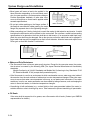
Installation and Wiring Precautions
! Caution
Do not step on or place a heavy object on the product. Doing so may result in injury.
! Caution
Do not cover the inlet or outlet ports and prevent any foreign objects from entering
the product. Doing so may result in fire.
! Caution
Be sure to install the product in the correct direction. Not doing so may result in malfunction.
! Caution
Provide the specified clearances between the Servo Driver and the control panel or
with other devices. Not doing so may result in fire or malfunction.
! Caution
Do not apply any strong impact. Doing so may result in malfunction.
! Caution
Be sure to wire correctly and securely. Not doing so may result in motor runaway,
injury, or malfunction.
! Caution
Be sure that all the mounting screws, terminal screws, and cable connector screws
are tightened to the torque specified in the relevant manuals. Incorrect tightening
torque may result in malfunction.
! Caution
Use crimp terminals for wiring. Do not connect bare stranded wires directly to terminals. Connection of bare stranded wires may result in burning.
! Caution
Always use the power supply voltage specified in the User’s Manual. An incorrect
voltage may result in malfunction or burning.
! Caution
Take appropriate measures to ensure that the specified power with the rated voltage
and frequency is supplied. Be particularly careful in places where the power supply
is unstable. An incorrect power supply may result in malfunction.
! Caution
Install external breakers and take other safety measures against short-circuiting in
external wiring. Insufficient safety measures against short-circuiting may result in
burning.
! Caution
Provide an appropriate stopping device on the machine side to secure safety. (A
holding brake is not a stopping device for securing safety.) Not doing so may result in
injury.
! Caution
Provide an external emergency stopping device that allows an instantaneous stop of
operation and power interruption. Not doing so may result in injury.
! Caution
Take appropriate and sufficient countermeasures when installing systems in the following locations:
S Locations subject to static electricity or other forms of noise.
S Locations subject to strong electromagnetic fields and magnetic fields.
S Locations subject to possible exposure to radioactivity.
S Locations close to power supplies.
2-2
Chapter 2
System Design and Installation
2-1
Installation
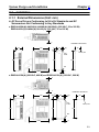
2-1-1 External Dimensions (Unit: mm)
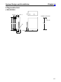
H AC Servo Drivers Conforming to UL/cUL Standards and AC
Servomotors Not Conforming to Any Standards
D R88D-UA02H(A)/-UA03H(A)/-UA04H(A)/-UA08H(A) (200 VAC, 30 to 200 W)
R88D-UA03L(A)/-UA04L(A)/-UA10L(A) (100 VAC, 30 to 100 W)
5
4
Installation dimensions
55
5
130
45
(5)
45
(6)
Three, M4
Two,
6 dia.
160
149
149
R3
5
(165)
6
D R88D-UA12H(A) (200 VAC, 400 W) and R88D-UA12L(A) (100 VAC, 200 W)
5
4
75
130
(6)
Installation dimensions
5
60
(5)
60
Two,
6 dia.
160
Three, M4
149
149
R3
(165)
5
6
2-3
Chapter 2
System Design and Installation
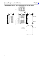
D R88D-UA20H(A) (200 VAC, 750 W) and R88D-UA15LA (100 VAC, 300 W)
3.5
7
105
130
90
(8)
6
Two, 6 dia.
160
149
Two, R3
5
(165)
6
6
90
Installation
dimensions
Four, M4
149
2-4
Chapter 2
System Design and Installation
H AC Servo Drivers Conforming to EC Directives
D R88D-UA02V/-UA03V/-UA04V/-UA08V (200 VAC, 30 to 200 W)
R88D-UA03W/-UA04W/-UA10W (100 VAC, 30 to 100W)
Installation dimensions
Two, 6 dia.
Three, M4
D R88D-UA12V (200 VAC, 400 W) and R88D-UA12W (100 VAC, 200W)
Installation dimensions
Two, 6 dia.
Three, M4
2-5
Chapter 2
System Design and Installation
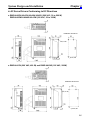
D R88D-UA20V (200 VAC, 750 W) and R88D-UA15W (100 VAC, 300W)
Two, 6 dia.
Two, R3
Installation dimensions
Four, M4
2-6
Chapter 2
System Design and Installation
H Regeneration Unit
D R88A-RG08UA
(15) (6)
25
Dia.: 6
Installation dimensions
Two, M4
160 130 149
149
R3
15
5
6
(18.5)
130
25
50
2-7
Chapter 2
System Design and Installation
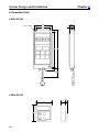
H Parameter Units
D R88A-PR02U
Two, 4.5 dia.
18.5
63
50
7
125 135
(8)
1000
D R88A-PR03U
54
57.5
2-8
15
6.9
Chapter 2
System Design and Installation
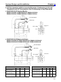
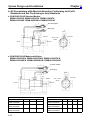
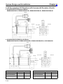
H AC Servomotors with Incremental Encoders Conforming to UL/cUL
Standards and AC Servomotors Not Conforming to Any Standards
D 30-W/50-W/100-W Standard Models:
R88M-U03030HA, R88M-U05030HA, R88M-U10030HA
R88M-U03030LA, R88M-U05030LA, R88M-U10030LA
300±30
35
Encoder adapter
Motor plug
6.5
18
14 dia.
300±30
6
6h6 dia.
2.5
Two, 4.3 dia.
30h7 dia.
17
9.5
5
Four, R3.7
6
40
46 dia.
33
40
LL
25
L
D 30-W/50-W/100-W Models with Brake:
R88M-U03030HA-B, R88M-U05030HA-B, R88M-U10030HA-B
R88M-U03030LA-B, R88M-U05030LA-B, R88M-U10030LA-B
300±30
35
Encoder adapter
Motor plug
21
14 dia.
2.5
Two, 4.3 dia.
30h7 dia.
17
5
33
Four, R3.7
4
46 dia.
40
9.5
6.5
6h6 dia.
300±30
LB
40
LL
25
L
Standard Models
Model
L
Models with Brake
LL
S
Model
L
LL
LB
S
R88M-U03030HA
R88M-U03030LA
94.5
69.5
6
R88M-U03030HA-B
R88M-U03030LA-B
126
101
31.5
6
R88M-U05030HA
R88M-U05030LA
102.0
77.0
6
R88M-U05030HA-B
R88M-U05030LA-B
133.5
108.5
31.5
6
R88M-U10030HA
R88M-U10030LA
119.5
94.5
8
R88M-U10030HA-B
R88M-U10030LA-B
160
135
40.5
8
2-9
Chapter 2
System Design and Installation
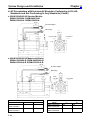
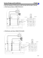
H AC Servomotors with Incremental Encoders Conforming to UL/cUL
Standards and Not Conforming to Any Standards (Contd.)
D 200-W/300-W/400-W Standard Models:
R88M-U20030HA, R88M-U40030HA
R88M-U20030LA, R88M-U30030LA
300±30
35
Encoder adapter
Motor plug
21
14 dia.
12
3
Four, 5.5 dia.
50h7 dia.
17
6
Four, R5.3
70 dia.
60
7
14h6 dia.
300±30
5.2
34
60
LL
30
L
D 200-W/300-W/400-W Models with Brake:
R88M-U20030HA-B, R88M-U40030HA-B
R88M-U20030LA-B, R88M-U30030LA-B
300±30
35
Encoder adapter
Motor plug
21
14 dia.
Four,
5.5 dia.
50h7 dia.
3
34
Four, R5.3
60
12
6
70 dia.
7
17
5.5
14h6 dia.
300±30
5.2
60
39.5
LL
30
L
Standard Models
Model
Models with Brake
L
LL
Model
L
LL
R88M-U20030HA
R88M-U20030LA
126.5
96.5
R88M-U20030HA-B
R88M-U20030LA-B
166
136
R88M-U40030HA
R88M-U30030LA
154.5
124.5
R88M-U40030HA-B
R88M-U30030LA-B
194
164
2-10
Chapter 2
System Design and Installation
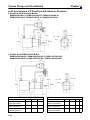
H AC Servomotors with Incremental Encoders Conforming to UL/cUL
Standards and Not Conforming to Any Standards (Contd.)
D 750-W Standard Models: R88M-U75030HA
300±30
35
Encoder adapter
Motor plug
21
14 dia.
300±30
8
15
3
Four, R8.2
35
80
90 dia.
16h6 dia.
Four, 7 dia.
70h7 dia.
8
17
5.2
34
80
145
40
185
D 750-W Models with Brake: R88M-U75030HA-B
300±30
35
Encoder adapter
Motor plug
21
14 dia.
300±30
8
15
Four, R8.2
3
35
34
44.5
90 dia.
Four, 7 dia.
80
70h7 dia.
8
16h6 dia.
17
5.2
80
189.5
40
229.5
2-11
Chapter 2
System Design and Installation
H AC Servomotors with Absolute Encoders Conforming to UL/cUL
Standards and Not Conforming to Any Standards
D 30-W/50-W/100-W Standard Models:
R88M-U03030TA, R88M-U05030TA, R88M-U10030TA
R88M-U03030SA, R88M-U05030SA, R88M-U10030SA
Encoder adapter
Motor plug
14 dia.
Sh6 dia.
Four, R3.7
Two, 4.3 dia.
46 dia.
53 dia.
30h7 dia.
D 30-W/50-W/100-W Models with Brake:
R88M-U03030TA-B, R88M-U05030TA-B, R88M-U10030TA-B
R88M-U03030SA-B, R88M-U05030SA-B, R88M-U10030SA-B
Encoder adapter
Motor plug
14 dia.
Sh6 dia.
Four, R3.7
Two, 4.3 dia.
46 dia.
30h7 dia.
53 dia.
Standard Models
Model
L
Models with Brake
LL
S
Model
L
LL
LB
S
R88M-U03030TA
R88M-U03030SA
117.5
92.5
6
R88M-U03030TA-B
R88M-U03030SA-B
149
124
31.5
6
R88M-U05030TA
R88M-U05030SA
125
100
6
R88M-U05030TA-B
R88M-U05030SA-B
156.5
131.5
31.5
6
R88M-U10030TA
R88M-U10030SA
142.5
117.5
8
R88M-U10030TA-B
R88M-U10030SA-B
183
158
40.5
8
2-12
Chapter 2
System Design and Installation
H AC Servomotors with Absolute Encoders Conforming to UL/cUL
Standards and Not Conforming to Any Standards (Contd.)
D 200-W/300-W/400-W Standard Models:
R88M-U20030TA, R88M-U40030TA, R88M-U20030SA, R88M-U30030SA
Encoder adapter
Motor plug
14 dia.
14h6 dia.
Four, R5.3
Four, 5.5.dia.
70 dia.
50h7 dia.
D 200-W/300-W/400-W Models with Brake:
R88M-U20030TA-B, R88M-U40030TA-B, R88M-U20030SA-B, U30030SA-B
Encoder adapter
Motor plug
14 dia.
14h6 dia.
Four, 5.5.dia.
Four, R5.3
70 dia.
50h7 dia.
Standard Models
Model
Models with Brake
L
LL
Model
L
LL
R88M-U20030TA
R88M-U20030SA
147.5
117.5
R88M-U20030TA-B
R88M-U20030SA-B
187
157
R88M-U40030TA
R88M-U30030SA
175.5
145.5
R88M-U40030TA-B
R88M-U30030-SA-B
215
185
2-13
Chapter 2
System Design and Installation
H AC Servomotors with Absolute Encoders Conforming to UL/cUL
Standards and Not Conforming to Any Standards (Contd.)
D 750-W Standard Models: R88M-U75030TA
Encoder adapter
Motor plug
14 dia.
Four, R8.2
Four, 7 dia.
16h6 dia.
90 dia.
70h7 dia.
D 750-W Models with Brake: R88M-U75030TA-B
Encoder adapter
Motor plug
14 dia.
Four, R8.2
Four, 7 dia.
16h6 dia.
90 dia.
70h7 dia.
2-14
Chapter 2
System Design and Installation
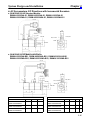
H AC Servomotors, EC Directives with Incremental Encoders
D 30-W/50-W/100-W Standard Models:
R88M-U03030VA-S1, R88M-U05030VA-S1, R88M-U10030VA-S1
R88M-U03030WA-S1, R88M-U05030WA-S1, R88M-U10030WA-S1
14 dia.
Sh6 dia.
Four, R3.7
Two, 4.3 dia.
46 dia.
30h7 dia.
D 30-W/50-W/100-W Models with Brake:
R88M-U03030VA-BS1, R88M-U05030VA-BS1, R88M-U10030VA-BS1
R88M-U03030WA-BS1, R88M-U05030WA-BS1, R88M-U10030WA-BS1
14 dia.
Four, R3.7
Two, 4.3 dia.
Sh6 dia.
46 dia.
30h7 dia.
Standard Models
Model
R88M-U03030VA-S1
R88M-U03030WAS1
R88M-U05030VA-S1
R88M-U05030WA-S1
R88M-U10030VA-S1
R88M-U10030WA-S1
Models with Brake
L
94.5
LL
69.5
6
S
102.0
77.0
6
119.5
94.5
8
Model
R88M-U03030VA-BS1
R88M-U03030WA-BS1
R88M-U05030VA-BS1
R88M-U05030WA-BS1
R88M-U10030VA-BS1
R88M-U10030WA-BS1
L
126
LL
101
LB
31.5
S
6
133.5
108.5
31.5
6
160
135
40.5
8
2-15
Chapter 2
System Design and Installation
H AC Servomotors, EC Directives with Incremental Encoders (Contd.)
D 200-W/300-W/400-W Standard Models:
R88M-U20030VA-S1, R88M-U40030VA-S1, R88M-U20030WA-S1, R88M-U30030WA-S1
14 dia.
14h6 dia.
Four, R5.3
Four, 5.5 dia.
70 dia.
50h7 dia.
D 200-W/300-W/400-W Models with Brake:
R88M-U20030VA-BS1, R88M-U40030VA-BS1, R88M-U20030WA-BS1, U30030WA-BS1
14 dia.
14h6 dia.
Four, 5.5 dia.
Four, R5.3
70 dia.
50h7 dia.
Standard Models
Model
R88M-U20030VA-S1
R88M-U20030WA-S1
R88M-U40030VA-S1
R88M-U30030WA-S1
2-16
Models with Brake
L
LL
126.5
96.5
154.5
124.5
Model
R88M-U20030VA-BS1
R88M-U20030WA-BS1
R88M-U40030VA-BS1
R88M-U30030WA-BS1
L
LL
166
136
194
164
Chapter 2
System Design and Installation
H AC Servomotors, EC Directives with Incremental Encoders (Contd.)
D 750-W Standard Models: R88M-U75030VA-S1
14 dia.
Four, R8.2
Four, 7 dia.
16h6 dia.
90 dia.
70h7 dia.
D 750-W Models with Brake: R88M-U75030VA-BS1
14 dia.
Four, R8.2
Four, 7 dia.
16h6 dia.
90 dia.
70h7 dia.
2-17
Chapter 2
System Design and Installation
H AC Servomotors, EC Directives with Absolute Encoders
D 30-W/50-W/100-W Standard Models:
R88M-U03030XA-S1, R88M-U05030XA-S1, R88M-U10030XA-S1
R88M-U03030YA-S1, R88M-U05030YA-S1, R88M-U10030YA-S1
14 dia.
Four, R3.7
Sh6 dia.
Two, 4.3 dia.
46 dia.
53 dia.
30h7 dia.
D 30-W/50-W/100-W Models with Brake:
R88M-U03030XA-BS1, R88M-U05030XA-BS1, R88M-U10030XA-BS1
R88M-U03030YA-BS1, R88M-U05030YA-BS1, R88M-U10030YA-BS1
14 dia.
Four, R3.7
Sh6 dia.
Two, 4.3 dia.
46 dia.
53 dia.
30h7 dia.
Standard Models
Model
R88M-U03030XA-S1
R88M-U03030YAS1
R88M-U05030XA-S1
R88M-U05030YA-S1
R88M-U10030XA-S1
R88M-U10030YA-S1
2-18
Models with Brake
L
117.5
LL
92.5
6
S
125
100
6
142.5
117.5
8
Model
R88M-U03030XA-BS1
R88M-U03030YA-BS1
R88M-U05030XA-BS1
R88M-U05030YA-BS1
R88M-U10030XA-BS1
R88M-U10030YA-BS1
L
149
LL
124
LB
31.5
S
6
156.5
131.5
31.5
6
183
158
40.5
8
Chapter 2
System Design and Installation
H AC Servomotors, EC Directives with Absolute Encoders (Contd.)
D 200-W/300-W/400-W Standard Models:
R88M-U20030XA-S1, R88M-U40030XA-S1, R88M-U20030YA-S1, R88M-U30030YA-S1
14 dia.
14h6 dia.
Four, R5.3
Four, 5.5 dia.
70 dia.
50h7 dia.
D 200-W/300-W/400-W Models with Brake:
R88M-U20030XA-BS1, R88M-U40030XA-BS1, R88M-U20030YA-BS1, U30030YA-BS1
14 dia.
14h6 dia.
Four, 5.5 dia.
Four, R5.3
70 dia.
50h7 dia.
Standard Models
Model
Models with Brake
L
LL
Model
L
LL
R88M-U20030XA-S1
R88M-U20030YA-S1
147.5
117.5
R88M-U20030XA-BS1
R88M-U20030YA-BS1
187
157
R88M-U40030XA-S1
R88M-U30030YA-S1
175.5
145.5
R88M-U40030XA-BS1
R88M-U30030YA-BS1
215
185
2-19
Chapter 2
System Design and Installation
H AC Servomotors, EC Directives with Absolute Encoders (Contd.)
D 750-W Standard Models: R88M-U75030XA-S1
14 dia.
Four, R8.2
Four, 7 dia.
16h6 dia.
90 dia.
80
70h7 dia.
D 750-W Models with Brake: R88M-U75030XA-BS1
14 dia.
Four, R8.2
Four, 7 dia.
16h6 dia.
90 dia.
70h7 dia.
2-20
Chapter 2
System Design and Installation
H Shaft Dimensions of Motors With Keys (Incremental and Absolute)
Standard U-series AC Servomotors do not have keys on the shafts. The dimensions of motors with keys
(produced on order) are shown below. Motors with keys are indicated by adding “-S1” to the end of the
model number. Key slots are based on JIS B1301-1976.
D 30-W/50-W Models
Standard: R88M-U03030jj-S1, R88M-U05030jj-S1
With Brake: R88M-U03030jj-BS1, R88M-U05030jj-BS1
14
Dia.: 6h6
1.2
2
2
D 100-W Models
Standard: R88M-U10030jj-S1
With Brake: R88M-U10030jj-BS1
14
Dia.: 8h6
1.8
3
3
D 200-W/300-W/400-W Models
Standard: R88M-U20030jj-S1, R88M-U40030jj-S1, R88M-U30030jj-S1
With Brake: R88M-U20030jj-BS1, R88M-U40030jj-BS1, R88M-U30030jj-BS1
20
Dia.: 14h6
3
5
5
D 750-W Models
Standard: R88M-U75030jj-S1
With Brake: R88M-U75030jj-BS1
30
Dia.: 16h6
3
5
5
2-21
Chapter 2
System Design and Installation
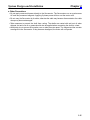
2-1-2 Installation Conditions
H AC Servo Drivers
D Space Around Drivers
• Install Servo Drivers according to the dimensions shown in the following illustration to ensure proper
heat dispersion and convection inside the panel. Also install a fan for circulation if Servo Drivers are
installed side by side to prevent uneven temperatures from developing inside the panel.
• Mount the Servo Drivers vertically (so that the model number and writing can be read).
ÉÉÉÉÉÉÉÉÉÉÉÉÉÉÉÉÉÉÉÉÉÉ
ÉÉÉÉÉÉÉÉÉÉÉÉÉÉÉÉÉÉÉÉÉÉ
ÉÉÉÉÉÉÉÉÉÉÉÉÉÉÉÉÉÉÉÉÉÉ
ÉÉÉÉÉÉÉÉÉÉÉÉÉÉÉÉÉÉÉÉÉÉ
ÉÉÉÉÉÉÉÉÉÉÉÉÉÉÉÉÉÉÉÉÉÉ
ÉÉÉÉÉÉÉÉÉÉÉÉÉÉÉÉÉÉÉÉÉÉ
ÉÉÉÉÉÉÉÉÉÉÉÉÉÉÉÉÉÉÉÉÉÉ
ÉÉÉÉÉÉÉÉÉÉÉÉÉÉÉÉÉÉÉÉÉÉ
ÉÉÉÉÉÉÉÉÉÉÉÉÉÉÉÉÉÉÉÉÉÉ
ÉÉÉÉÉÉÉÉÉÉÉÉÉÉÉÉÉÉÉÉÉÉ
ÉÉÉÉÉÉÉÉÉÉÉÉÉÉÉÉÉÉÉÉÉÉ
ÉÉÉÉÉÉÉÉÉÉÉÉÉÉÉÉÉÉÉÉÉÉ
ÉÉÉÉÉÉÉÉÉÉÉÉÉÉÉÉÉÉÉÉÉÉ
Servo Driver
Servo Driver
W
30 mm min.
50 mm min.
Fan
Servo Driver
Fan
Side of Unit
W
W = 10 mm min.
50 mm min.
D Operating Environment
Be sure that the environment in which Servo Drivers are operated meets the following conditions.
• Ambient operating temperature:
0°C to +55°C
• Ambient operating humidity:
35% to 85% (RH, with no condensation)
• Atmosphere:
No corrosive gases.
D Ambient Temperature
• Servo Drivers should be operated in environments in which there is minimal temperature rise to
maintain a high level of reliability.
• Temperature rise in any Unit installed in a closed space, such as a control box, will cause the ambient
temperature to rise inside the entire closed space. Use a fan or a air conditioner to prevent the ambient temperature of the Servo Driver from exceeding 55°C.
• Unit surface temperatures may rise to as much as 30°C above the ambient temperature. Use heatresistant materials for wiring, and keep separate any devices or wiring that are sensitive to heat.
• The service life of a Servo Driver is largely determined by the temperature around the internal electrolytic capacitors. The service life of an electrolytic capacitor is affected by a drop in electrolytic volume and an increase in internal resistance, which can result in overvoltage alarms, malfunctioning
due to noise, and damage to individual elements. If a Servo Driver is always operated at the maximum ambient temperature of 55°C, then a service life of approximately 50,000 hours can be expected. A drop of 10°C in the ambient temperature will double the expected service life.
2-22
Chapter 2
System Design and Installation
D Keeping Foreign Objects Out of Units
• Place a cover over the Units or take other preventative measures to prevent foreign objects, such as
drill filings, from getting into the Units during installation. Be sure to remove the cover after installation is complete. If the cover is left on during operation, heat buildup may damage the Units.
• Take measures during installation and operation to prevent foreign objects such as metal particles,
oil, machining oil, dust, or water from getting inside of Servo Drivers.
H AC Servomotors
D Operating Environment
Be sure that the environment in which the Servomotor is operated meets the following conditions.
• Ambient operating temperature:
0°C to +40°C
• Ambient operating humidity:
20% to 80% (RH, with no condensation)
• Atmosphere:
No corrosive gases.
D Impact and Load
• The Servomotor is resistant to impacts of up to 10 G
{98 m/s2}. Do not subject it to heavy impacts or loads
during transport, installation, or positioning. In addition, do not hold onto the encoder, cable, or connector areas when transporting it.
• Always use a pulley remover to remove pulleys,
couplings, or other objects from the shaft.
• Secure cables so that there is no impact or load placed on the cable connector areas.
D Connecting to Mechanical Systems
• The axial loads for Servomotors are specified in section 5-2-4. If an axial load greater than that specified
is applied to a Servomotor, it will reduce the service
life of the motor bearings and may damage the motor
shaft. When connecting to a load, use couplings that
can sufficiently absorb mechanical eccentricity and
variation.
Ball screw center line
Motor shaft center line
Shaft core
displacement
Recommended Coupling
Name
Oldham coupling
Maker
Myghty Co., Ltd
• For spur gears, an extremely large radial load may
be applied depending on the gear precision. Use
spur gears with a high degree of accuracy (for example, JIS class 2: normal line pitch error of 6 µm max.
for a pitch circle diameter of 50 mm). If the gear precision is not adequate, allow backlash to ensure that
no radial load is placed on the motor shaft.
Backlash
Adjust backlash
by adjusting the
distance between
shafts.
2-23
Chapter 2
System Design and Installation
• Bevel gears will cause a load to be applied in the
thrust direction depending on the structural precision, the gear precision, and temperature changes.
Provide appropriate backlash or take other measures to ensure that no thrust load is applied which
exceeds specifications.
• Do not put rubber packing on the flange surface. If
the flange is mounted with rubber packing, the motor
flange may separate due to the tightening strength.
Bevel gear
Make moveable.
• When connecting to a V-belt or timing belt, consult the maker for belt selection and tension. A radial
load twice the belt tension will be placed on the motor shaft. Do not allow a radial load exceeding
specifications to be placed on the motor shaft due to belt tension. If an excessive radial load is applied, the motor shaft may be damaged. Set up the structure so that the radial load can be adjusted. A
large radial load may also be applied as a result of belt vibration. Attach a brace and adjust Servo
Driver gain so that belt vibration is minimized.
Pulley
Belt
Tension
Make adjustable.
Motor shaft
Load shaft
D Water and Drip Resistance
• The Servomotor does not have a water-proof structure. Except for the connector areas, the protective structure is covered by the following JEM (The Japan Electrical Manufacturers’ Association)
standards.
Models Conforming to UL/cUL Standards and Models Not Conforming to Any Standards: IP-42
EC Directive Models: IP-44 (except shaft penetration point)
• If the Servomotor is used in an environment in which condensation occurs, water may enter inside of
the encoder from the end surfaces of cables due to motor temperature changes. Either take measures to ensure that water cannot penetrate in this way, or use water-proof connectors. Even when
machinery is not in use, water penetration can be avoided by taking measures, such as keeping the
motor in servo-lock status, to minimize temperature changes.
• If machining oil with surfactants (e.g., coolant fluids) or their spray penetrate inside of the motor, insulation defects or short-circuiting may occur. Take measures to prevent machining oil penetration.
D Oil Seals
If the motor shaft is exposed to oil or grease, use a Servomotor with oil seals. (Contact your OMRON
representative for details.)
2-24
System Design and Installation
Chapter 2
D Other Precautions
• Do not apply commercial power directly to the Servomotor. The Servomotors run on synchronous
AC and use permanent magnets. Applying 3-phase power will burn out the motor coils.
• Do not carry the Servomotor by its cable, otherwise the cable may become disconnected or the cable
clamp may become damaged.
• Take measures to prevent the shaft from rusting. The shafts are coated with anti-rust oil when
shipped, but anti-rust oil or grease should also be applied when connecting the shaft to a load.
• Absolutely do not remove the encoder cover or take the motor apart. The magnet and the encoder
are aligned in the Servomotor. If they become misaligned, the motor will not operate.
2-25
Chapter 2
System Design and Installation
2-2
Wiring Products Conforming to UL/cUL and Wiring
Products Not Confrorming to Any Standards
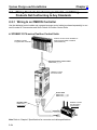
2-2-1 Wiring to an OMRON Controller
Use the dedicated control cables and a general-purpose control cable (purchased separately) to connect U-series AC Servomotors and Servo Drivers to Position Control Units.
H SYSMAC C/CV-series Position Control Units
SYSMAC C-series
Programmable Controller
Position Control Unit for SYSMAC Cseries Programmable Controllers
(C500-NC222-E)
General-purpose Control Cable
R88A-CPUjjjS
OMNUC U-series
AC Servo Driver
Power Cable
R88A-CAUjjjS
R88A-CAUjjjB
Encoder Cable
R88A-CRUjjjC
(Incremental)
OMNUC U-series
AC Servomotor
(Incremental)
Note Refer to Chapter 5 Specifications for connector and cable specifications.
2-26
Chapter 2
System Design and Installation
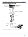
H SYSMAC CV-series Motion Control Units
SYSMAC C/CV-series
Programmable Controller
CV500-MC221/CV500-MC421
C200H-MC221
Motion Control Unit
Special Cables
R88A-CPUjjjM1 (for one-axis control)
R88A-CPUjjjM1 (for two-axis control)
OMNUC U-series
AC Servo Driver
Encoder Cable
R88A-CRUjjjC
(Incremental)
R88A-CSUjjjC
(Absolute)
Power Cable
R88A-CAUjjjS
R88A-CAUjjjB
OMNUC U-series
AC Servomotor
(Incremental, or
Absolute)
Note Refer to Chapter 5 Specifications for connector and cable specifications.
2-27
Chapter 2
System Design and Installation
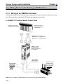
H OMNUC N115, N116, U43, and U45
N115
N116
U43/U45
Controller Cable
R88A-CPUjjjN
(for N115, N116, U43,
and U45)
OMNUC U-series
AC Servo Driver
Encoder Cable
R88A-CRUjjjC
(Incremental)
Power Cable
R88A-CAUjjjS
R88A-CAUjjjB
OMNUC U-series
AC Servomotor
(Incremental)
Note Refer to Chapter 5 Specifications for connector and cable specifications.
2-28
Chapter 2
System Design and Installation
2-2-2 Connector–Terminal Conversion Unit
The AC Servo Driver can be easily connected to the Connector–Terminal Conversion Unit through a
special cable without soldering.
Controllers
XW2B-40F5-P
Connector–Terminal
Conversion Unit
Connector Cable for
Connector–Terminal
Conversion Unit
R88A-CTUjjjN
OMNUC U-series
AC Servo Driver
Encoder Cable
R88A-CRUjjjC
(Incremental)
Power Cable
R88A-CAUjjjS
R88A-CAUjjjB
OMNUC U-series
AC Servomotor
(Incremental)
Note Refer to Chapter 5 Specifications for connector and cable specifications.
2-29
Chapter 2
System Design and Installation
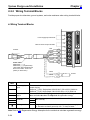
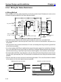
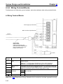
2-2-3 Wiring Terminal Blocks
Provide proper wire diameters, ground systems, and noise resistance when wiring terminal blocks.
H Wiring Terminal Blocks
Power supply input terminals
Main-circuit DC output terminals
Red
To Motor
White
Blue
Green
Power Cable
R88A-CAUjjjS
R88A-CAUjjjB (with brake)
(The broken lines indicate signal
lines for the brake. There is no
polarity on these lines.)
Black
Black
Terminal
Name
label
Power supply
R
input
T
P
N
U
V
W
Main circuit DC
output
24 VDC
Function
The commercial power supply input terminals for the main circuit and the
control circuitry.
y
R88D-UAjjH(A): Single-phase 200/230 VAC (170 to 253 V) 50/60 Hz
R88D-UAjjL(A): Single-phase 100/115 VAC (85 to 127 V) 50/60 Hz
The terminals for connecting
g Regeneration
g
Units ((R88A-RG08UA).
) Connect
these
h
terminals
i l when
h there
h
is
i a high
hi h level
l
l off regenerative
i energy.
Motor connection Red
These are the output terminals to the Servomotor. Be careful to wire
terminals
i l
h
correctly.
l
White them
Blue
Frame ground
Green The ground terminal for both the motor output and power supply input. Ground to a class-3 ground (to 100 Ω or less) or better.
Note Refer to 3-8 Regenerative Energy Absorption for the methods to calculate regenerative energy.
2-30
Chapter 2
System Design and Installation
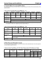
H Terminal Block Current and Wire Sizes
The following table shows the rated effective currents flowing to the Servo Driver and the sizes of the
electrical wires.
D Servo Drivers with 200-VAC Input (R88D-UAjjH(A))
Driver
(Watts)
R88D-UA02H(A)
(30 W)
R88D-UA03H(A) R88D-UA04H(A) R88D-UA08H(A) R88D-UA12H(A) R88D-UA20H(A)
(50 W)
(100 W)
(200 W)
(400 W)
(750 W)
Power supply input current (R, T)
1.3 A
1.5 A
2.5 A
4.0 A
6.0 A
11.0 A
Motor output current (U, V, W)
0.42 A
0.6 A
0.87 A
2.0 A
2.6 A
4.4 A
Power supply input terminal wire
size
0.75 mm2 or AWG 18 min.
1.25 mm2
2.0 mm2
Motor
output
o o ou
u
t
i l wire
i size
i
terminal
0.5 mm2 or AWG 20
Ground terminal
wire size
Use 2.0-mm2 external ground wires. Use the same wire as used for the motor output.
AWG 20 (see note) to AWG 18
Use OMRON standard cable. The applicable wire size for motor connectors is AWG22 to AWG18.
Note If the cable length is 15 meters or longer for a 750-W Servomotor, the momentary maximum torque at rotation speeds of 2,500 r/min or higher may drop by approximately 7%.
D Servo Drivers with 100-VAC Input (R88D-UAjjL(A))
Driver model
(Watts)
Power supply input current (R, T)
R88D-UA03L(A)
(30 W)
R88D-UA04L(A)
(50 W)
R88D-UA10L(A)
(100 W)
R88D-UA12L(A)
(200 W)
2.0 A
2.6 A
4.5 A
8.0 A
10.0 A
0.7 A
2.2 A
2.7 A
3.7 A
1.25 mm2
2 mm2
Motor output current (U, 0.63 A
V, W)
R88D-UA15LA
(300 W)
Power supply input terminal wire size
0.75 mm2 or AWG 18 min.
Motor output terminal
wire
i size
i
0.5 mm2 or AWG 20
AWG 20 to AWG 18
Use OMRON standard cable (AWG20). The applicable wire size for motor connectors is
AWG22 to AWG18.
Ground terminal wire
size
Use 2.0-mm2 external ground wires. Use the same wire as used for the motor output.
H Wire Sizes and Allowable Current
The following table shows allowable currents when there are three electrical wires. Use values equal to
or lower than the specified values.
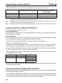
D Heat-resistant Vinyl Wiring, UL1007, Rated Temperature 80°C (Reference Value)
AWG size
20
--18
16
Nominal crosssectional area
2)
(
(mm
0.5
0.75
0.9
1.25
Configuration
((wires/mm2)
19/0.18
30/0.18
37/0.18
50/0.18
Conductive
resistance
(Ω/k )
(Ω/km)
39.5
26.0
24.4
15.6
Allowable current (A) for
ambient temperature
40°C
6.6
8.8
9.0
12.0
50°C
5.6
7.0
7.7
11.0
60°C
4.5
5.5
6.0
8.5
2-31
Chapter 2
System Design and Installation
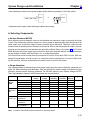
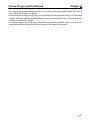
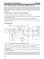
2-2-4 Wiring for Noise Resistance
H Wiring Method
Noise resistance will vary greatly depending on the wiring method used. Resistance to noise can be
increased by paying attention to the items described below.
Surge
Noise filter Contactor
MCCB absorber
X1
1
Servo Driver
R88DUjjjj
3
TB
R
TB
U
4
T
V
W
NF
AC power supply
2
E
Fuse
Servomotor
R88MUjjjjjj
Metal duct
M
CN2
RE
2 mm2 min.
3.5mm2
Class-3 ground
(to 100 Ω or less) Ground plate
Control board
ground
Controller power supply
Machine
ground
Thick power line
(3.5 mm2)
• Ground the motor’s frame to the machine ground when the motor is on a movable shaft.
• Use a grounding plate for the frame ground for each Unit, as shown in the illustration, and ground to a
single point.
• Use ground lines with a minimum thickness of 3.5 mm2, and arrange the wiring so that the ground lines
are as short as possible.
• If no-fuse breakers (MCCB) are installed at the top and the power supply line is wired from the lower
duct, use metal tubes for wiring and make sure that there is adequate distance between the input lines
and the internal wiring. If input and output lines are wired together, noise resistance will decrease.
• No-fuse breakers (MCCB), surge absorbers, and noise filters (NF) should be positioned near the input
terminal block (ground plate), and I/O lines should be isolated and wired using the shortest means
possible.
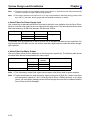
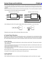
• Wire the noise filter as shown at the left in the following illustration. The noise filter should be installed
at the entrance to the control panel whenever possible.
Good: Separate input and output
1
AC input
Ground
3
NF
2
NO: Noise not filtered effectively
E
4
1
AC output
AC input
2
Ground
AC output
2-32
3
NF
E
4
Chapter 2
System Design and Installation
• Use twisted-pair cables for the power supply cables whenever possible, or bind the cables.
R
Driver
or
Driver
T
Binding
• Separate power supply cables and signal cables when wiring.
H Selecting Components
D No-fuse Breakers (MCCB)
When selecting no-fuse breakers, take into consideration the maximum output current and the inrush
current. The momentary maximum output for a servo system is approximately three times that of the
rated output, and a maximum output of three seconds can be executed. Therefore, select no-fuse
breakers with an operating time of at least five seconds at 300% of the rated maximum output. Generalpurpose and low-speed no-fuse breakers are generally suitable. Refer to the table in 2-2-3 Terminal
Block Wiring for the power supply input currents for each motor, and then add the current consumption
for the number of shafts, other controllers, etc., to make the selection.
The Servo Driver inrush current flows at a maximum of 50 A for 20 ms when 200 V is input. With lowspeed no-fuse breakers, a inrush current 7 to 8 times the rated current flows for 0.1 second. When making the selection, take into consideration the entire inrush current for the system.
D Surge Absorbers
Use surge absorbers to absorb surges from power supply input lines due to lightning, abnormal voltages, etc. When selecting surge absorbers, take into account the varistor voltage, the amount of surge
immunity, and the amount of energy resistance. For 200-VAC systems, use a varistor voltage of 470 V.
The surge absorbers shown in the following table are recommended.
Maker
Matsushita
El
Electric
i
Parts
Ishizuka
El
Electronics
i
Co
Co.
Okaya
Electric Ind.
Model
Varistor
voltage
Max. limit
voltage
Surge
immunity
Energy
resistance
Fuse
capacity
ERZV10D471(W)
ERZV14D471(W)
ERZV20D471(W)
ERZC20EK471(W)
Z10L471
Z15L471
Z21L471
Z25M471S
R.A.V
-781BWZ-2A
470 V
470 V
470 V
470 V
470 V
470 V
470 V
470 V
---
775 V
775 V
775 V
775 V
773 V
738 V
733 V
810 V
783 V
1,250 A
2,500 A
4,000 A
5,000A
1,000A
1,250 A
3,000 A
10,000 A
1,000 A
45 J
80 J
150 J
150 J
15 WSs
20 WSs
30 WSs
235 J
---
3 to 5 A
3 to 10 A
5 to 15 A
--3 to 5 A
3 to 5 A
5 to 10 A
-----
R.A.V
-781BXZ-2A
---
783 V
1,000 A
---
---
R.A.V
-401.621BYR-2
---
620 V
1,000 A
---
---
Note
1. The (W) Matsushita models are UL and CSA certified.
Note
2. Refer to manufacturers documentation for operating details.
Type
Disk
Block
Disk
Block
Block
2-33
Chapter 2
System Design and Installation
Note
3. The surge immunity is for a standard impulse current of 8/20 µs. If pulses are wide, either decrease the
current or change to a larger-capacity surge absorber.
Note
4. The energy resistance is the value for 2 ms. It may not be possible to retard high-energy pulses at less
than 700 V. In that case, absorb surges with an insulated transformer or reactor.
D Noise Filters for Power Supply Input
Use a noise filter to attenuate extraneous noise and to diminish noise radiation from the Servo Driver.
Select a noise filter with a load current of at least twice the rated current. The following table shows noise
filters that reduce by 40 dB noise between 200 kHz and 30 MHz.
Maker
Tokin
Model
LF-210N
LF-215N
LF-220N
Rated current
10 A
15 A
20 A
Remarks
For single-phase
g
To attenuate noise at frequencies of 200 kH or less, use an insulated transformer and a noise filter. For
high frequencies of 30 MHz or more, use a ferrite core and a high-frequency noise filter with a throughtype capacitor.
D Noise Filters for Motor Output
Use noise filters without built-in capacitors on the Servomotor output lines. The following table shows
the noise filters that are recommended for motor output.
Maker
Tokin
Fuji Electrochemical Co.
Model
LF-310KA
LF-320KA
ESD-R-47B
RN80UD
Rated
current
10 A
20 A
-----
Remarks
Three-phase block noise filter
EMI core for radiation noise
10-turn for radiation noise
Note 1. The Servomotor output lines cannot use the same noise filters used for power supplies.
Note 2. Typical noise filters are used with power supply frequencies of 50/60 Hz. If these noise filters
are connected to outputs of 7.8 to 11 KHz (the Servo Driver’s PWM frequency), a very large
(about 100 times larger) leakage current will flow through the noise filter’s condenser and the
Servo Driver could be damaged.
2-34
Chapter 2
System Design and Installation
D Surge Killers
Install surge killers for loads that have induction coils, such as relays, solenoids, brakes, clutches, etc.
The following table shows types of surge killers and recommended products.
Type
Diode
Features
Diodes are relatively small devices such as relays used
for loads when reset time is not an issue. The reset time
is increased because the surge voltage is the lowest
when power is cut off. Used for 24/48-VDC systems.
Thyristor
or
Varistor
Thyristor and varistor are used for loads when induction
coils are large, as in electromagnetic brakes, solenoids,
etc., and when reset time is an issue. The surge voltage
when power is cut off is approximately 1.5 times that of
the varistor.
Capacitor
+ resistor
Use capacitors and resistors for vibration absorption of
surge when power is cut off. The reset time can be
shortened by proper selection of the capacitor or resistor.
Recommended products
Use a fast-recovery diode with a
short reverse recovery time.
Fuji Electric Co., ERB44-06 or equivalent
Select varistor voltage as follows:
24-VDC system varistor:
100-VDC system varistor:
100-VAC system varistor:
200-VAC system varistor:
Okaya Electric Ind.
39 V
200 V
270 V
470 V
CR-50500 0.5 µF-50 Ω
CRE-50500 0.5 µF-50 Ω
S2-A-0
0.2 µF-500 Ω
Note Thyristors and varistors are made by the following companies. Refer to manufacturers documentation for
operating details. Thyristors: Ishizuka Electronics Co.
Varistors: Ishizuka Electronics Co., Matsushita Electric Parts
D Contactors
When selecting contactors, take into consideration the circuit’s inrush current and the momentary maximum current. The Servo Driver inrush current is 50 A, and the momentary maximum current is approximately twice the rated current. The following table shows the recommended contactors.
Maker
OMRON
Model
G6C-2BND
LY2-D
G7L-2A-BUBJ
J7AN-E3
LC1-D093A60
Rated current
10 A
10 A
25 A
15 A
11 A
Momentary maximum current
------120 A
200 A
Coil voltage
24 VDC
24 VDC
24 VDC, 200 to 240 VAC
24 VDC
24 VDC, 200/220 VAC,
200 to 240 VAC
D Leakage Breakers
• Select leakage breakers designed for inverters.
• Since switching operations take place inside the Servo Driver, high-frequency current leaks from the
armature of the Servomotor. With inverter leakage breakers, high-frequency current is not detected,
preventing the breaker from operating due to leakage current.
• When selecting leakage breakers, also remember to add the leakage current from devices other than
the Servomotor, such as machines using a switching power supply, noise filters, inverters, and so on.
• For detailed information about the selection methods of leakage breakers, refer to catalogs provided
by manufacturers.
2-35
System Design and Installation
Chapter 2
• The following table shows the Servomotor leakage currents for each Servo Driver.
Driver
Leakage current (direct)
(including high-frequency current)
Leakage current (resistor-capacitor,
in commercial power supply frequency range)
R88D-UA02H to -UA08H 80 mA
3 mA
R88D-UA12H
60 mA
4 mA
R88D-UA20H
110 mA
5 mA
Note 1. Leakage current values shown above are for motor power lines of 10 m or less. The values will change
depending on the length of power cables and the insulation.
Note
2. Leakage current values shown above are for normal temperatures and humidity. The values will
change depending on the temperature and humidity.
Note
3. Leakage current for 100-VAC-input Servomotors is approximately half that of the values shown above.
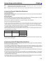
H Improving Encoder Cable Noise Resistance
The following encoder signals are used.
Incremental Encoders:
A, B, and S phase. The frequency for A- or B-phase signals is 154 kHz max.; the transmission speed for
S-phase signals is 616 kbps.
Absolute Encoders:
A, B, and Z phase, plus the absolute encoder signal. The frequency for A- or B-phase signals is 76.8 kHz
max.; the transmission speed for absolute encoder signals is 9.6 kbps.
Follow the wiring methods outlined below to improve encoder noise resistance.
• Be sure to use dedicated encoder cables.
• If lines are interrupted in the middle, be sure to connect them with connectors, making sure that the
cable insulation is not peeled off for more than 50 mm. In addition, be sure to use shielded wire.
• Do not coil cables. If cables are long and are coiled, mutual induction and inductance will increase and
will cause malfunctions. Be sure to use cables fully extended.
• When installing noise filters for encoder cables, use ferrite cores. The following table shows the recommended ferrite core models.
Maker
Tokin
TDK
Name
EMI core
Clamp filter
Model
ESD-QR-25-1
ZCAT2032-0930
ZCAT3035-1330
ZCAT2035-0930A
• Do not wire the encoder cable in the same duct as power cables and control cables for brakes, solenoids, clutches, and valves.
H Improving Control I/O Signal Noise Resistance
Position can be affected if control I/O signals are influenced by noise. Follow the methods outlined below for the power supply and wiring.
• Use completely separate power supplies for the control power supply (especially 24 VDC) and the
external operation power supply. In particular, be careful not to connect two power supply ground
wires. Install a noise filter on the primary side of the control power supply.
2-36
System Design and Installation
Chapter 2
• For speed and torque command input lines, be sure to use twisted-pair shielded cable, and connect
both ends of the shield wire to ground.
• If the control power supply wiring is long, noise resistance can be improved by adding 1-µF laminated
ceramic capacitors between the control power supply and ground at the Servo Driver input section
and the controller output section.
• For encoder output lines (A, B, and Z phases, plus the absolute encoder signal), be sure to use
twisted-pair shielded cable, and connect both ends of the shield wire to ground.
2-37
Chapter 2
System Design and Installation
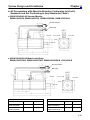
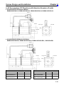
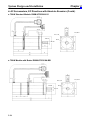
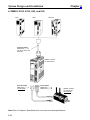
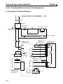
2-2-5 Peripheral Device Connection Examples
H Connecting to Peripheral Devices
R
T
Single-phase, 200/230 VAC, 50/60 Hz (R88D-UjjjH(A))
Single-phase, 100/115 VAC, 50/60 Hz (R88D-UjjjL(A))
MCCB
1
E
3
2
NF
4
Noise filter
Main-circuit
power supply
Main-circuit connector
ON
OFF
1MC
Class-3 ground
(to 100 Ω or less)
1MC
Surge killer
X
X
1MC
PL
OMNUC U-series
AC Servo Driver
XB
OMNUC U-series
AC Servomotor
B
24VDC
R
U
T
V
CN1
X
R88D-CAUjjjS
(-CAUjjjB)
Power Cable
Servo error display
M
34 ALM
W
24 VDC
35 ALMCOM
Class-3 ground
(to 100 Ω or less)
User’s control device
X
CN1
CN2
R88A-CRUjjjC (Incremental)
R88A-CSUjjjC (Absolute)
Encoder Cable
E
CN1
R88A-CPUjjjS
General-purpose
Control Cable
2-38
BKIR 7
XB
24 VDC
OGND 10
Chapter 2
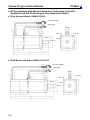
System Design and Installation
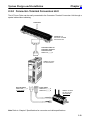
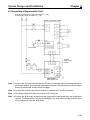
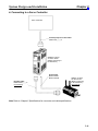
H Connecting a Regeneration Unit
Single-phase 200/230 VAC 50/60 Hz: R88D-UAjjH(A)
or 100/115 VAC 50/60 Hz: R88D-UAjjL(A)
OMNUC U-series Servo Driver
12 to 24 VDC
External
regeneration
resistor
R88A-RG08UA
Regeneration Unit
Note 1. Remove the short bar from between the RG and JP terminals when connecting external regeneration resistor. If the external regeneration resistor is connected without removing the
short bar, the internal circuitry will be damaged.
Note 2. Connect the external regeneration resistor to between the P and RG terminals.
Note 3. The Regeneration Unit does not conform to EC Directives.
Note 4. Connect the ALM output so that the power supply will be interrupted when the contacts are
opened. The Regeneration Unit may be damaged if it is used without including a power interruption sequence using the ALM output.
2-39
Chapter 2
System Design and Installation
2-3
Wiring Products Conforming to EC Directives
2-3-1 Wiring to an OMRON Controller
Use general-purpose control cable (purchased separately) to connect U-series AC Servomotors and
Servo Drivers (models conforming to EC Directives) to Motion Control Units.
H SYSMAC C/CV-series Motion Control Units
SYSMAC C/CV-series
Programmable Controller
Motion Control Unit
CV500-MC221/MC421
C200H-MC221
Dedicated Control Cables
R88A-CPUjjjM1 (for 1 axis)
R88A-CPUjjjM2 (for 2 axes)
OMNUC U-series
AC Servo Driver
(Model conforming to
EC Directives)
Power Cable
R88A-CAU001
R88A-CAU01B
Encoder Cable
R88A-CRUDjjjC
(Incremental)
R88A-CSUDjjjC
(Absolute)
Note Refer to Chapter 5 Specifications for connector and cable specifications.
2-40
OMNUC U-series
AC Servomotor
(Model conforming
to EC Directives)
(Incremental)
(Absolute)
Chapter 2
System Design and Installation
H Connecting to a Servo Controller
Servo Controller
General-purpose Control Cable
R88A-CPUjjjS
OMNUC U-series
AC Servo Driver
(Model conforming to
EC Directives)
Power Cable
R88A-CAU001
R88A-CAU01B
Encoder Cable
R88A-CRUDjjjC
(Incremental)
OMNUC U-series
AC Servomotor
(Model conforming
to EC Directives)
(Incremental)
Note Refer to Chapter 5 Specifications for connector and cable specifications.
2-41
Chapter 2
System Design and Installation
2-3-2 Wiring Terminal Blocks
Provide proper wire diameters, ground systems, and noise resistance when wiring terminal blocks.
H Wiring Terminal Blocks
Power supply input terminals
Main-circuit DC output terminals
Red
To Motor
White
Blue
Power Cable
R88A-CAU001
R88A-CAU01B (with brake)
(The broken lines indicate signal
lines for the brake. There is no
polarity on these lines.)
Green
Black
Black
Terminal
Name
label
Power supply
L1
input
L2
+
–
U
V
W
24 VDC
Function
The commercial power supply input terminals for the main circuit and the
control circuitry.
y
R88D-UAjjV: Single-phase 200/230 VAC (170 to 253 V) 50/60 Hz
R88D-UAjjV: Single-phase 100/115 VAC (85 to 127 V) 50/60 Hz
Main circuit DC
When there is a high level of regenerative energy in a multi-axis system, the
output
+ terminals can be connected together and the – terminals can be connected
together to increase the ability to absorb regenerative energy.
Motor connection Red
These are the output terminals to the Servomotor. Be careful to wire
terminals
i l
h
correctly.
l
White them
Blue
Frame ground
Green Ground to a class-3 ground (to 100 Ω or less) or better.
Note Refer to 3-8 Regenerative Energy Absorption for the methods to calculate regenerative energy.
2-42
Chapter 2
System Design and Installation
H Terminal Block Current and Wire Sizes
The following table shows the rated effective currents flowing to the Servo Driver and the sizes of the
electrical wires.
D Servo Drivers with 200-VAC Input (R88D-UAjjV)
Driver
(Watts)
R88D-UA02V
(30 W)
R88D-UA03V
(50 W)
R88D-UA04V
(100 W)
R88D-UA08V
(200 W)
R88D-UA12V
(400 W)
R88D-UA20V
(750 W)
Power supply input
current (L1, L2)
1.3 A
1.5 A
2.5 A
4.0 A
6.0 A
11.0 A
Motor output current
(U, V, W)
0.42 A
0.6 A
0.87 A
2.0 A
2.6 A
4.4 A
Power supply input
terminal wire size
0.75 mm2 or AWG 18 min.
1.25 mm2
2.0 mm2
Motor
output
o o ou
u
t
i l wire
i size
i
terminal
0.5 mm2 or AWG 20
Protective earth terminal wire size
Use 2.0-mm2 external ground wires. Use the same wire as used for the motor output.
AWG 20 (see note) to AWG 18
Use OMRON standard cable. The applicable wire size for motor connectors is AWG22 to AWG18.
Note If the cable length is 15 meters or longer for a 750-W Servomotor, the momentary maximum torque at rotation speeds of 2,500 r/min or higher may drop by approximately 7%.
D Servo Drivers with 100-VAC Input (R88D-UAjjW)
Driver model
(Watts)
R88D-UA03W
(30 W)
Power supply input current (L1, L2)
2.0 A
Motor output current (U, 0.63 A
V, W)
R88D-UA04W
(50 W)
R88D-UA10W
(100 W)
R88D-UA12W
(200 W)
R88D-UA15W
(300 W)
2.6 A
4.5 A
8.0 A
10.0 A
0.7 A
2.2 A
2.7 A
3.7 A
1.25 mm2
2 mm2
Power supply input terminal wire size
0.75 mm2 or AWG 18 min.
Motor output terminal
wire
i size
i
0.5 mm2 or AWG 20
AWG 20 to AWG 18
Use OMRON standard cable (AWG20). The applicable wire size for motor connectors is
AWG22 to AWG18.
Protective earth terminal wire size
Use 2.0-mm2 external ground wires. Use the same wire as used for the motor output.
H Wire Sizes and Allowable Current
The following table shows allowable currents when there are three electrical wires. Use values equal to
or lower than the specified values.
D Heat-resistant Vinyl Wiring, UL1007, Rated Temperature 80°C (Reference Value)
AWG size
20
--18
16
Nominal crosssectional area
2)
(
(mm
0.5
0.75
0.9
1.25
Configuration
((wires/mm2)
19/0.18
30/0.18
37/0.18
50/0.18
Conductive
resistance
(Ω/k )
(Ω/km)
39.5
26.0
24.4
15.6
Allowable current (A) for
ambient temperature
40°C
6.6
8.8
9.0
12.0
50°C
5.6
7.0
7.7
11.0
60°C
4.5
5.5
6.0
8.5
2-43
Chapter 2
System Design and Installation
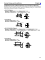
2-3-3 Wiring Products Conforming to EMC Directives
Model conforming to EC Directive will meet the requirements of the EMC Directives EN55011 Class A
Group 1 (EMI) and EN50082-2 (EMS) if they are wired under the conditions described in this section. If
the connected devices, wiring, and other conditions cannot be made to fulfill the installation and wiring
conditions when the product is incorporated into a machine, the compliance of the overall machine must
be confirmed.
The following conditions must be met to conform to EMC Directives.
• The Servo Driver must be installed in a metal case (control panel).
• Noise filters and surge absorbers must be installed on all power supply lines.
• Shielded cables must be used for all I/O signal lines and encoder lines. (Use tin-plated, soft copper
wires for the shield weaving.)
• All cables leaving the control panel must be wired in metal ducts or conduits with blades.
• Ferrite cores must be attached to the shielded cable and the shield must be clamped directly to the
ground plate to ground it.
H Wiring Methods
Control panel
Metal plate
Noise
filter
AC power
supply
Metal
duct or
conduit
Surge
absorber
Brake power supply
Metal
duct or
conduit
Contactor
Noise
2m
max.
Ground (100 Ω max.)
filter
0.5 m
max.
Controller
power
supply
Ferrite
core
Clamp
Ferrite
core
Clamp
Controller
Clamp
1 m max.
Grounding plate
Controller
Note 1. The cable winding for the ferrite core must be 1.5 turns.
Note 2. Remove the sheath from the cable and ground it directly to the metal plate at the clamps.
• Ground the motor’s frame to the machine ground when the motor is on a movable shaft.
• Use the grounding plate for the protective earth for each Unit, as shown in the illustration, and ground
to a single point.
• Use ground lines with a minimum thickness of 3.5 mm2, and arrange the wiring so that the ground lines
are as short as possible.
• If no-fuse breakers (MCCB) are installed at the top and the power supply line is wired from the lower
duct, use metal tubes for wiring and make sure that there is adequate distance between the input lines
and the internal wiring. If input and output lines are wired together, noise resistance will decrease.
2-44
Chapter 2
System Design and Installation
• No-fuse breakers (MCCB), surge absorbers, and noise filters (NF) should be positioned near the input
terminal block (ground plate), and I/O lines should be isolated and wired using the shortest means
possible.
• Wire the noise filter as shown at the left in the following illustration. The noise filter should be installed
at the entrance to the control panel whenever possible.
Good: Separate input and output
1
AC input
3
NF
2
NO: Noise not filtered effectively
1
AC output
E
4
AC input
3
NF
2
Ground
E
4
Ground
AC output
• Use twisted-pair cables for the power supply cables whenever possible, or bind the cables.
L1
L1
Driver
or
Driver
L2
L2
Binding
• Separate power supply cables and signal cables when wiring.
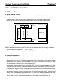
H Control Panel Structure
Any gaps in the cable entrances, mounting screws, cover, or other parts of a control panel can allow
electric waves to leak from or enter the control panel. The items described in this section must be abided
by in panel design and selection to ensure that electric waves cannot leak or enter the control panel.
D Case Structure
• Use a metal control panel with welded joints on the top, bottom, and all sides. The case must be electrically conductive.
• When assembling the control panel, remove the coating from all joints (or mask the joints when coating) to ensure electrical conductivity.
• Be sure that no gaps are created when installing the control panel, as gaps can be caused by distortion
when tightening screws.
• Be sure there are not any electrically conductive parts that are not in electrical contact.
• Ground all Units mounted in the control panel to the panel case.
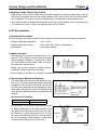
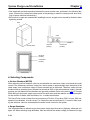
D Cover Structure
• Use a metal cover.
• Use a water-proof structure, as shown in the following diagram, and be sure there are no gaps.
2-45
Chapter 2
System Design and Installation
• Use electrically conductive packing between the cover and the case, as shown in the following diagram. (Remove the coating the contact points of the packing (or mask the contact points when coating) to ensure electrical conductivity.)
• Be sure that no gaps are created when installing the cover, as gaps can be caused by distortion when
tightening screws.
Case
Case
Cover
Oil-proof
packing
Control panel
Conductive
packing
Oil-proof
packing
Conductive
packing
Case (inside)
H Selecting Components
D No-fuse Breakers (MCCB)
When selecting no-fuse breakers, take into consideration the maximum output current and the inrush
current. The momentary maximum output for a servo system is approximately three times that of the
rated output, and a maximum output of three seconds can be executed. Therefore, select no-fuse
breakers with an operating time of at least five seconds at 300% of the rated maximum output. Generalpurpose and low-speed no-fuse breakers are generally suitable. Refer to the table in 2-2-3 Terminal
Block Wiring for the power supply input currents for each motor, and then add the current consumption
for the number of shafts, other controllers, etc., to make the selection.
The Servo Driver inrush current flows at a maximum of 50 A for 20 ms when 200 V is input. With lowspeed no-fuse breakers, a inrush current 7 to 8 times the rated current flows for 0.1 second. When making the selection, take into consideration the entire inrush current for the system.
D Surge Absorbers
Use surge absorbers to absorb surges from power supply input lines due to lightning, abnormal voltages, etc. When selecting surge absorbers, take into account the varistor voltage, the amount of surge
2-46
Chapter 2
System Design and Installation
immunity, and the amount of energy resistance. For 200-VAC systems, use a varistor voltage of 470 V.
The surge absorbers shown in the following table are recommended.
Maker
Okaya
y
El
Electric
i Ind.
I d
Model
Max. limit
voltage
783 V
783 V
R.A.V-781BYZ-2
R.A.V-781BXZ-4
Surge
immunity
1,000 A
1,000 A
Type
Block
Remarks
For power supply line
For power supply line
ground
Note
1. Refer to manufacturers documentation for operating details.
Note
2. The surge immunity is for a standard impulse current of 8/20 µs. If pulses are wide, either decrease the
current or change to a larger-capacity surge absorber.
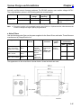
D Noise Filters
Use the following noise filters on the power supplies for the Servo Driver and brake. These filters are
manufactured by Okaya Electric Ind.
Application
200 V, 30 to 100 W
100 V, 30 or 50 W
Brake power supply
Model
Rated
current
SUP-P5HEPR-4
5A
200 V, 200 or 400 W SUP-P8H100 V, 100 W
EPR-4
8A
200 V, 750 W
100 V, 200 or 300W
10 A
SUP-P10HEPR-4
Test voltage
Between
terminals:
1,250 V rms,
50/60 Hz, 60 s
Between
terminals and
case:
2,000 V rms,
50/60 Hz, 60 s
Insulation
resistance
Between
terminals and
case:
6,000 MΩ min.
(at 500 VDC)
Attenuation
characteristic
Leakage
current
(
(max.)
)
0.6 mA
(at 250 V
rms 60 Hz)
Normal
(MHz)
Common
(MHz)
0.5 to 30
0.2 to 30
0.6 to 30
0.3 to 30
0.7 to 30
0.4 to 30
The appearance of the noise filters is shown below. Screw terminals are used.
Two, 4,8 dia.
Five, M4
2-47
Chapter 2
System Design and Installation
D Surge Killers
Install surge killers for loads that have induction coils, such as relays, solenoids, brakes, clutches, etc.
The following table shows types of surge killers and recommended products.
Type
Diode
Features
Diodes are relatively small devices such as relays used
for loads when reset time is not an issue. The reset time
is increased because the surge voltage is the lowest
when power is cut off. Used for 24/48-VDC systems.
Thyristor
or
Varistor
Thyristor and varistor are used for loads when induction
coils are large, as in electromagnetic brakes, solenoids,
etc., and when reset time is an issue. The surge voltage
when power is cut off is approximately 1.5 times that of
the varistor.
Capacitor
+ resistor
Use capacitors and resistors for vibration absorption of
surge when power is cut off. The reset time can be
shortened by proper selection of the capacitor or resistor.
Recommended products
Use a fast-recovery diode with a
short reverse recovery time.
Fuji Electric Co., ERB44-06 or equivalent
Select varistor voltage as follows:
24-VDC system varistor:
100-VDC system varistor:
100-VAC system varistor:
200-VAC system varistor:
Okaya Electric Ind.
39 V
200 V
270 V
470 V
CR-50500 0.5 µF-50 Ω
CRE-50500 0.5 µF-50 Ω
S2-A-0
0.2 µF-500 Ω
Note Thyristors and varistors are made by the following companies. Refer to manufacturers documentation for
operating details. Thyristors: Ishizuka Electronics Co.
Varistors: Ishizuka Electronics Co., Matsushita Electric Parts
D Contactors
When selecting contactors, take into consideration the circuit’s inrush current and the momentary maximum current. The Servo Driver inrush current is 50 A, and the momentary maximum current is approximately twice the rated current. The following table shows the recommended contactors.
Maker
OMRON
Model
J7AN-E3
Rated current
15 A
Momentary maximum current
120 A
Coil voltage
24 VDC
D Leakage Breakers
• Select leakage breakers designed for inverters.
• Since switching operations take place inside the Servo Driver, high-frequency current leaks from the
armature of the Servomotor. With inverter leakage breakers, high-frequency current is not detected,
preventing the breaker from operating due to leakage current.
• When selecting leakage breakers, also remember to add the leakage current from devices other than
the Servomotor, such as machines using a switching power supply, noise filters, inverters, and so on.
• For detailed information about the selection methods of leakage breakers, refer to catalogs provided
by manufacturers.
• The following table shows the Servomotor leakage currents for each Servo Driver.
Driver
Leakage current (resistor-capacitor,
in commercial power supply frequency range)
R88D-UA02V to -UA08V 80 mA
3 mA
R88D-UA12V
60 mA
4 mA
R88D-UA20V
110 mA
5 mA
Note 1. Leakage current values shown above are for motor power lines of 10 m or less. The values will change
depending on the length of power cables and the insulation.
2-48
Leakage current (direct)
(including high-frequency current)
System Design and Installation
Chapter 2
Note
2. Leakage current values shown above are for normal temperatures and humidity. The values will
change depending on the temperature and humidity.
Note
3. Leakage current for 100-VAC-input Servomotors is approximately half that of the values shown above.
H Improving Encoder Cable Noise Resistance
Incremental Encoders:
A, B, and S phase. The frequency for A- or B-phase signals is 154 kHz max.; the transmission speed for
S-phase signals is 616 kbps.
Absolute Encoders:
A, B, and Z phase, plus the absolute encoder signal. The frequency for A- or B-phase signals is 76.8 kHz
max.; the transmission speed for absolute encoder signals is 9.6 kbps.
Follow the wiring methods outlined below to improve encoder noise resistance.
• Be sure to use dedicated encoder cables.
• If lines are interrupted in the middle, be sure to connect them with connectors, making sure that the
cable insulation is not peeled off for more than 50 mm. In addition, be sure to use shielded wire.
• Do not coil cables. If cables are long and are coiled, mutual induction and inductance will increase and
will cause malfunctions. Be sure to use cables fully extended.
• When installing noise filters for encoder cables, use ferrite cores. The following table shows the recommended ferrite core models.
Maker
Tokin
TDK
Name
EMI core
Clamp filter
Model
ESD-QR-25-1
ZCAT2032-0930
ZCAT3035-1330
ZCAT2035-0930A
• Do not wire the encoder cable in the same duct as power cables and control cables for brakes, solenoids, clutches, and valves.
H Improving Control I/O Signal Noise Resistance
Position can be affected if control I/O signals are influenced by noise. Follow the methods outlined below for the power supply and wiring.
• Use completely separate power supplies for the control power supply (especially 24 VDC) and the
external operation power supply. In particular, be careful not to connect two power supply ground
wires. Install a noise filter on the primary side of the control power supply.
• For speed and torque command input lines, be sure to use twisted-pair shielded cable, and connect
both ends of the shield wire to ground.
• If the control power supply wiring is long, noise resistance can be improved by adding 1-µF laminated
ceramic capacitors between the control power supply and ground at the Servo Driver input section
and the controller output section.
• For encoder output (A, B, and Z phase, plus the absolute encoder signal) lines, be sure to use twistedpair shielded cable, and connect both ends of the shield wire to ground.
2-49
Chapter 2
System Design and Installation
2-3-4 Peripheral Device Connection Examples
H Connecting to Peripheral Devices
R
T
Single-phase, 200/230 VAC, 50/60 Hz (R88D-UjjjV)
Single-phase, 100/115 VAC, 50/60 Hz (R88D-UjjjW)
MCCB
1
E
3
2
NF
4
Noise filter
Main-circuit
power supply
Main-circuit connector
ON
OFF
1MC
Class-3 ground
(to 100 Ω or less)
1MC
Surge killer
X
X
1MC
PL
OMNUC U-series
AC Servo Driver
XB
OMNUC U-series
AC Servomotor
B
24VDC
L1
U
L2
V
CN1
X
R88D-CAU001
(-CAU001B)
Power Cable
Servo error display
M
34 ALM
W
24 VDC
35 ALMCOM
User’s control device
X
CN1
CN2
Class-3 ground
(to 100 Ω or less)
E
R88A-CRUjjjC (Incremental)
R88A-CSUjjjC (Absolute)
Encoder Cable
R88A-CPUjjjS
General-purpose
Control Cable
CN1
BKIR 7
24 VDC
OGND 10
2-50
XB