1
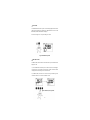
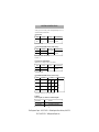
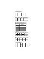
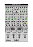
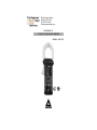
99 Washington Street
Melrose, MA 02176
Fax 781-665-0780
TestEquipmentDepot.com
USER MANUAL
A UNIQUE CLAMP-ON MULTIMETER
MODEL: ACD-330T
C
US
LISTED
ACDC-3000
TABLE OF CONTENTS
SAFETYINFORMATION
• INTRODUCTION
USING THE METER SAFELY
LCD DISPLAY ILLUSTRATION
GETTING ACQUAINTED WITH YOUR METER
•ALIGNMENTMARKS
•ROTARY SWITCH
•INPUTTERMINAL
•PUSH BUTTONS
PUSH-BUTTON OPERATIONS
POWER-ON OPTIONS
SPECIALFUNCTIONS INSTRUCTION
•Dynamic Recording
•Data Hold
•Zero (Relative)
•Analog Bargraph
•Auto Power Off and Sleep Mode
•Disable Auto Power Off
•Demonstrate Annunciator
•Continuity Function For Ohms Measurement
•1 ms Peak Hold
•Backlit LCD for easy reading in the dark
HOW TO OPERATE
• AC CURRENTMEASUREMENT
• DISTRIBUTION TRANSFORMERS MEASUREMENT
• ADJUSTABLE SPEED MOTOR CONTROLLERS
• AC MOTOR CURRENTMEASUREMENT
• AC VOLTAGE MEASUREMENT
• RESISTANCE/ CONTINUITYMEASUREMENT
• DIODE CHECK
GENERALSPECIFICATIONS
ACCESSORIES AND REPLACEMENT PARTS
ELECTRICALSPECIFICATIONS
CURRENTHARMONICS THEORY
• TRUE RMS MEASUREMENTS
• WAVEFORM COMPARISON
MAINTENANCE
• SERVICE
• BATTERY REPLACEMENT
• CLEANING
1
2
4
5
6
6
6
7
8
9
11
11
12
12
14
15
16
17
17
17
18
19
19
19
21
23
25
27
28
29
30
30
31
33
34
35
37
37
37
37
Test Equipment Depot - 800.517.8431 - 99 Washington Street Melrose, MA 02176
FAX 781.665.0780 - TestEquipmentDepot.com
SAFETY INFORMATION
SAFETY INFORMATION
To ensure that youuse the meter safety, follow the safety guidelines listed below.
• This meter is for indoor use, altitude up to 2000m..
• Avoid working alone. Take precautions when working around moving parts.
• Use extreme caution what working around bare conductors or him bars. Accidental
contact with the conductor could result in electric shock.
• Use the meter only as specified in this manual. Otherwise, the protection provided by
the meter may be impared.
• Never measure current while the test leads are inserted into the input terminals.
• Do use the meter if it looks damaged.
• Inspect the leads for damaged insulation or exposed metal. Check test leads continuity.
Replace damaged leads.
• Disconnect the power and discharge all high-voltage capacitors before testing in the
resistance, continuity, and diode function.
• Use caution when working above 60VDC or 30VAC RMS, Such voltages pose a
shock hazard.
• When making measurements, keep your fingers behind the finger guards, on the probe.
• Set the proper function and range before attaching the meter to circuit. To avoid
damaging the meter disconnect the test leads from test points before changing functions.
• Read this operation manual completely before using the meter and follow all
safety instructions.
• The meter is safety-certified in compliance with UL311-1, C22.2 NO.1010.1-92 and
EN61010 (IEC1010-1, IEC 1010-2-031, IEC 1010-2-032). Installation Category II 1000V
or Installation Category III 600V. In order to maintain its insulation properties, please be
sure to use with ULListed Category II 1000Vor Category III 600V probes.
• Installation Category (CAT) II is an environment with smaller transient over voltage than
Installation Category III.
• CE requirement: Under the influence of R.F. field according to standard, the supplied test
leads will pick up induced noise. To have better shielding effect, a short test lead should
be used. The following tests are required in order to conform to CE:
1. IEC 801-2:ESD (electro static discharge) test.
2. IEC 801-3:RFI (Radio Frequency Interference) test.
Condition: 27 ˜˜500MHZ, signal intensity is 3 volts per meter.
3. IEC 801-4:EFT(electro fast transient) test.
4. EN 55011: EMI (electro magnetic interference) test.
1
A UNIQUE CLAMP-ON MULTIMETER
INTRODUCTION
Measuring current accurately is a difficult job in today's industrial plants and commercial
buildings. An increasing number of personal computers, adjustable speed motor drives,
and other types electronic equipment come on-line every day. These, devices draw current in short pulses, and are referred to as non-linear loads.
Non-linear loads draw high peak -currents, causing harmonies in the load current. This
may result in unexplained circuit breaker tripping, or dangerous overheating of neutral
conductors and transformers. Currents containing harmonics, can only be accurately
measured with a true-rms meter or Clamp meter.
This CLAMP-ON MULTIMETER is shown in Figure 1. This meter his many functions
which, are shown below:
• TRUE RMS measurement fornon-linearand traditional loads.
• 1 ms Peak Hold feature to capture glitch orin-rush current.
• Dual Display Mode: Current vs Frequency or Voltage vs Frequency.
• Diode measurement.
• Dynamic Recording helps to record the variation of tests.
• Hand Guard forprevention of accidental contact with conductors.
• Carrying case with shoulderstrap.
• Data Hold to freeze displayed digital value.
• Relative (zero) function.
• Auto and Manual Ranging.
• Backlit display foreasy reading in dark places.
2
Test Equipment Depot - 800.517.8431 - 99 Washington Street Melrose, MA 02176
FAX 781.665.0780 - TestEquipmentDepot.com
Diode check.
Hand guard design
for more safety.
Ohm measurement
Dynamic recording
helps to record the
variation of tests.
And one touch DATA
HOLD.
Voltage measurement
Current measurement.
Rotary switch for easy
operation.
Dual display to indicate the
V/ frequency or A/
frequency simultaneously.
1ms Peak Hold for
glitch capture.
Backlit display for
easy reading in the
dark place.
AUTO/MANUALSELECT.
Relative (ZERO)
mode for deviation
measurements.
Dual display V/ frequency
or A/ frequency.
Figure 1. A Unique Clamp-ON Multimeter
3
Test Equipment Depot - 800.517.8431 - 99 Washington Street Melrose, MA 02176
FAX 781.665.0780 - TestEquipmentDepot.com
USING THE METER SAFELY
WARNING
Read “SAFETYINFORMATION” before using the meter.
NOTE
Some typical tests are provided in this manual. These tests are designed to help you understand how to use the Meter. Consult original manufacturer service manual for the test procedures that apply to your particular piece of equipment.
Your Clamp-on multimeter is a hand-held, battery-operated instrument for testing and
troubleshooting electrical and electronic systems. If the meter is damaged or something is
missing, contact the place of purchase immediately.
A WARNING identifies conditions and actions that pose hazard(s) to the user; a CAUTION identifies conditions and actions that may damage the Meter. International electrical symbols used are explained in Table 1.
AC ~ Alternating Current
DC ~ Direct Current
AC and DC ~ Alternating and Direct Current
Ground
Double Insulation
See Explanation in the Manual
Table 1. International Electrical Symbols
FRENCH WARNING
This meter has a warning on the bottom chassis case that needs to be followed prior to opening
the case. We have transfered this to French translation as listed below:
ATTENTION
POUR EVITER UN CHOC ELECTRIQUE,
ENLECER LES CORDONS D’ESSAI AVANT
D’OUVRIR LE BOITIER.
NE BAS UTILISER LORSQUE LE BOITIER
ESTOUVERT
4
LCD DISPLAY ILLUSTRATION
1)
2)
3)
-
4)
5)
DC
AC
6)
7)
8)
9)
10)
11)
12)
13)
14)
15)
16)
17)
18)
19)
20)
21)
22)
@OFF
: Negative Polarity Annunciator
: Auto Power Off Enabled Annunciator
: Low Battery Annunciator
: Direct Voltage Annunciator
: Alternating Current or Voltage
Annunciator
AUTO
: Indicates AUTO range mode Annunciator
DΗ
: Data hold annunciator
DΗ MAX : Peak Hold annunciator (1 mS response)
MAX AVG MIN : Dynamic recording mode, Present Reading
MAX
: Maximum reading
MIN
: Minimum reading
AVG
:Average reading
•)))
: Continuity function annunciator
: Diode Measurement
kHz
: Unit of frequency
V
: Unit of voltage measurement
A
: Unit of Current measurement
kΩ
: Unit of resistance (ohm) measurement
∆
: Zero (delta) mode annunciator
8.8.8.8
: Digital display for A, V, Ω, and diode
8000 8000
: Analog bar-graph annunciator
IIIIIIIIIIII
with scale indicator
- 8.8.8.8 : Digital display for frequency
Figure 2. LCD Display
5
Test Equipment Depot - 800.517.8431 - 99 Washington Street Melrose, MA 02176
FAX 781.665.0780 - TestEquipmentDepot.com
Getting Acquainted With Your Meter
MARK
ALIGNMENT MARKS
Conductor
MARK
Mark
Protective
Hand Guard
Figure 3. Alignment Marks
In order to meet the meter accuracy specifications when making a current measurement,
the conductor must be inside the jaws and centered within the indicated marks as much
as possible. (see Figure 3)
Rotary Switch
To turn the meter on and select a function, turn the rotary switch (Figure 4) to a switch
setting.The whole display lights for one second.
Then the meter is ready for use. (If you press and hold down any pushbutton while turning the meter from OFF to ON, the display remains, lit until the pushbutton is released.)
1) Power Off Position
2) AC Current measurements.
3) AC or DC Voltage.Default is AC voltage.
4) Ohms and Continuity. The continuity buzzer sounds when test value that is
displayed is below 100 counts.
5) Diode and Audible Continuity measurements.
5
4
3
2
1
)
•))
)
•))
Ω
H V
H A
OFF
Figure 4. Rotary Switch
6
INPUT TERMINAL
WARNING
To avoid damaging the meter, do not exceed input limits shown below in Table 1:
INPUT
TERMINAL
ROTARY SWITCH
FUNCTION
AC 400 ~ 1000V(CAT II)
AC 400 ~ 600V (CAT III)
DC 400 ~1000V(CAT II)
DC 400 ~600V (CAT III)
AC 400 ~ 1000A
OHM (Ω)
•))) )
DIODE (
V-Ω-
INPUTLIMIT
CAT II
1000VAC/ 1000VDC
CAT III
600V
& COM
1000ARMS
Clamp Jaw
V-Ω-
& COM
600VRMS
Table 1. Input limit Specifications
The meter has two input terminals ( Figure 5) that are protected against overloads to the
limits shown in the specifications.
1) Common terminal for all measurements (except current).
2) Volts, Ohms, Diode, measurements.
1
2
Figure 5. Input Terminal
7
Test Equipment Depot - 800.517.8431 - 99 Washington Street Melrose, MA 02176
FAX 781.665.0780 - TestEquipmentDepot.com
3. Press to toggle
“DH” ON/OFF.
4. Press and hold
for more than
1 second to
set Dynamic
Recording then
press to step
through MAX,MIN,
AVG and present
reading.
1. Press to select
DC or AC.
Press and hold for
more than 1 second
to toggle, between
PEAK and DC
or AC.
6. In manual range
press to step up 1
range at a time.
Press and hold for 1
sec to select Auto
range
2. Press to toggle
Continuity(•))) )ON/OFF
for ohm measurement.
Press to set
frequency
measurements.
In V or A range.
5. Press to toggle the
Relative (ZERO)
mode ON/OFF.
Figure 6. Push Buttons
8
Push-button Operations
The operation of the push-buttons are outlined below. When a button is pushed, an annunciator lights, and the unit beeps. Turning the rotary switch to another switch setting resets
all push buttons to their default states. The pushbuttons are shown in Figure 6 (Page 08).
1. Shift / Peak m:
• This push-button is used for selecting the measurement of either an Alternating or
Direct source, or for selecting the PEAK hold function.
• Press this button momentarily to toggle DC and AC voltage test.
• To select PEAK hold, press and hold this button until the display shows " DH MAX"
and indicates the PEAK hold mode.
2. Hold m : DATA HOLD orRefresh Data Hold
• The data HOLD function allows operator to freeze the displayed digital value while
the analog bargraph continues to display the present reading.
• Press this button momentarily to toggle DH on or off. The display shows "DH" to
indicate the hold function.
• If you select " Refresh Data Hold " by Power-ON Options, the reading is updated to
the display automatically when the reading changes. The beeper sounds a tone to
remind user, that an update has occurred.
• Press this button momentarily to toggle DH on or off.
3. MAX a MIN m : Dynamic Recording
• To enter or exit dynamic recording mode, press and hold this button to toggle
recording mode on or off.
• Records maximum, minimum, and calculates true average.
• Press this button momentarily to cycle through maximum, minimum, average
and present (MAX AVG MIN) readings.
• The beeper sounds when a new maximum, or minimum value is recorded.
4. Zero /* m :
• Push this button momentarily to zero the residual current. Note: Allow the meter to
stabilize before zeroing the display. The " A " will also be displayed.
• Press this button for more than I second to toggle Backlight ON or OFF. Backlight
turns off automatically after 30 seconds.
9
Test Equipment Depot - 800.517.8431 - 99 Washington Street Melrose, MA 02176
FAX 781.665.0780 - TestEquipmentDepot.com
5. •))) / Hz m : Continuity, Frequency
• In the Ω position, press this button momentarily to toggle"-)))" continuity ON/OFF.
The continuity buzzer sounds when test value is below 100 counts (10.0 Ω on auto
range). Pushing this button for more than 1 second will exit the continuity function
and return to the auto-ranging ohm measurement.
• Press to restart I ms PEAK hold test after entering PEAK mode.
• In the voltage and Current tests, push this button momentarily to enter dual display
mode. The small digits will indicate frequency reading. The frequency test always auto
range measuring.
6. AUTO / RANGE m :
• In auto-range press this button momentarily to select manual range and turn off the
"AUTO" annunciator.
• In manual range, press this button momentarily to step up 1 range at one time, press
this button for more than 1 second to enter auto-range.
• In auto-range, the " AUTO " annunciator is lit and the meter will select an appropriate
range for measurement being made. If a reading is greater than maximum available
range, " OL"(overload) is displayed on the screen. The meter selects a lower range
when reading is less than about 9% of full scale.
10
POWER-ON OPTIONS
SELECTING POWER -ON OPTIONS
Some options can be selected only when you turn the meter on. These power-on options
are listed in Table 2 To select power-on options, press and hold down pushdown while
turning the rotary switch to any ON position. Power-on options remain selected until the
meter is turned off.
PUSH BUTTON
DH
m
MAX • MIN
Hz
m
•)) )
OPTION DESCRIPTION
Demonstrate Annunciators
To demonstrate the annunciators, Full annunciators are
displayed. Press any buttons momentarily to exit
demonstrate mode.
Disable auto-poweroff
In general, the auto-power off function turns the meter off if neither rotary switch nor push button is activated for 15 minutes.
You can disable auto-power off function by this option. When
auto-power off is disabled the meter will stay on continuously.
Auto-power off is auto disable in Dynamic Recording.
Enable "Refresh Data Hold".
Turns off all beeper functions.
Table 2. Power-On Options
SPECIAL FUNCTIONS INSTRUCTIONS
This clamp-on multimeter provides the operator with various functions including:
Dynamic Recording
Data Hold
Zero(Relative)
Analog Bargraph
Auto Power Off and Sleep Mode
Disable Auto Power Off
Demonstrate Annunciator of Display
Continuity Function For Ohms Measurement
1 ms Peak Hold
Backlit LCD for easy reading in the dark
11
Test Equipment Depot - 800.517.8431 - 99 Washington Street Melrose, MA 02176
FAX 781.665.0780 - TestEquipmentDepot.com
DYNAMIC RECORDING
The dynamic recording mode can be used to catch intermittent and turn on or turn off
surges, verify performance, measure while you are away, or take readings while you are
operating the equipment under test and can not watch the meter. Refer to Figure 7.
The average reading is useful for smoothing out unstable or changing inputs, estimating
the percent of time a circuit is operational, or verifying circuit performance.
The operational procedures are described below:
1 ) Press and hold the "MAX * MIN"pushbutton to toggle recording mode on or off. The
dynamic recording mode is indicated when the MAX AVG MIN annunciator turns on.
The present value is stored to memories of maximum, minimum and average.
2) Press this button momentarily to cycle through maximum, minimum,average and
present readings. The MAX, MIN, AVG annunciator turns on respectively
to indicate what value is being displayed. See Figure 3)
3) The beeper sounds when a new maximum or minimum value is recorded.
4) If an overload is recorded the averaging function is stopped. An average
value becomes " OL"(overload).
5) In dynamic recording, the auto power off feature is disabled and the " Off" turns off.
6) By selecting dynamic recording in the auto range, the meter will record the value
of MAX, MIN or AVG for different ranges.
7) The record speed of dynamic recording is about 100 milli-seconds (0.1 second).
8) The average value is the true average of all measured values taken since the
recording mode was entered.
12
Figure 7. Display of Dynamic Recording
13
Test Equipment Depot - 800.517.8431 - 99 Washington Street Melrose, MA 02176
FAX 781.665.0780 - TestEquipmentDepot.com
DATA HOLD
The data HOLD function allows operator to freeze the displayed digital value while the
analog bargraph displays present readings. Press "DW HOLD button to enter the data
HOLD mode, and the "DWannunciator is displayed.
Press the button again to exit. The present reading is now shown.
Figure 8. Data Hold Operation
ZERO (RELATIVE)
The ZERO (relative) function subtracts a stored value from the present measurement and
displays the result.
1 ) Press the ZERO button momentarily to set the relative mode. This sets the display to
zero and stores the present reading as a reference value. The " m " annunciator will also
be displayed. Press this button again to exit the relative mode.
2) The ZERO (relative) mode can be set in both the autorange or manual range mode.
The'relative mode can't be set when an overload has occurred.
Figure 9. Relative (Zero) Operation.
14
ANALOG BARGRAPH
The analog bargraph display provides a 12-segment analog reading representation.
The unit of the bargraph is 100 counts/bar.
Figure 10. Analog Bargraph.
15
Test Equipment Depot - 800.517.8431 - 99 Washington Street Melrose, MA 02176
FAX 781.665.0780 - TestEquipmentDepot.com
AUTO POWER OFFAND SLEEPMODE
There are two modes for power saving:
1) The instrument will enter the "sleep" mode within 15 minutes, unless:
1-1. Any push buttons have been pressed
1-2. The rotary switch has been changed to another function
1-3. The unit has been set to Dynamic recording mode
1-4. The unit has been set to 1 ms PEAK hold mode.
1-5. The auto power off has been disabled with powerup option
2) In the sleep mode, the LCD will display a blinking "@OFF, . . . "annunciator.
2-1. To wake-up sleep mode, press any push button for 0.5 sec or
rotate rotary switch.
2-2. Without wake-up, after 15 minutes, the meter will automatically
shut off completely.
3) You must turn the rotary switch to the OFF position, then turn it back to a function to
activate the meter after an auto power off.
Figure 11. Sleep Mode
16
DISABLE AUTO POWER OFF
When the meter is to be used for long periods of time you may want to disable the auto
power off, Once the auto power off function is disabled, the meter will stay on continuously. The meter is shut off by turning the rotary switch to the OFF position.
To activate this function, press and hold the "HOLD/MAX * MIN" button and turn the
rotary switch from the OFF position to the desired function. When all annunciators are
displayed, press any button momentarily to exit demonstrate mode, and the "Off" annunciator will be off.
DEMONSTRATE ANNUNCIATOR
To demonstrate the annunciators, press "HOLDIMAX * MIN" button and turn on the
meter simultaneously. All annunciators will be displayed. Press any button to exit demonstrate mode. Auto power off will be disabled.
Figure 12. Demonstrate Annunciator
CONTINUITYFUNCTION FOR OHMS MEASUREMENT
To enable the continuity function, set the meter to the Ω range. Press -))) button momentarily to toggle the CONTINUITYfunction ON/OFF. The continuity range is 0400~O Ω
and the beeper will sound if the resistance is less than 10.0 0. If another range is selected, the unit will beep if the value displayed is less than 100 counts. Momentarily pushing
this button again will toggle the beeper and annunciator on or off.
(40MΩ Range
(400Ω Range)
Figure 13. Continuity Operation
17
Test Equipment Depot - 800.517.8431 - 99 Washington Street Melrose, MA 02176
FAX 781.665.0780 - TestEquipmentDepot.com
1 ms PEAK HOLD
You can use this Meter to analyze components such as power distribution transformers
and power factor correction capacitors. The additional features allow the measurement of
the half-cycle peak current by using the 1 ms peak hold feature. This allows the determination of the crest factor:
Crest factor= Peak value/True rms value
1) Press PEAK button for more than 1 second to toggle I ms peak hold mode ON/OFF.
2) Press PEAK button momentarily to select PEAK+ measurement after entering the
peak mode. The display shows "DH MAX" to indicate the PEAK +. See Figure 14.
3) If the reading is " OL", then you can push RANGE button momentarily to change
measuring range and restart the PEAK+ measurement after setting the peak mode.
4) Press .))) button to re-set the 1 ms peak hold again after setting peak mode.
Note: A crest factor of 1.4 indicates a sinusoidal waveform.
Figure 14. 1 ms Peak Hold Display
18
BACKLITDISPLAY FOR EASYREADING IN THE DARK
Press ❊ button for more than 1 second to toggle backlight ON/OFF. Backlight turns off
automatically after 30 seconds. To disable backlight(off automatically after 30 seconds),
use POWER-ON option (see page 17).
Figure 15. Backlit Display.
AC CURRENTMEASUREMENT
WARNING: MAKE CERTAIN THAT ALL TEST LEADS ARE DISCONNECTED
FROM THE METER TERMINALS.
1) Set the rotary switch to " A ".
2) Open the meter jaws and clamp around a single conductor. The most accurate reading
will be obtained by keeping the conductor aligned with the centering marks on the
jaws.Make sure that the jaws are fully closed.
3) Read the display.
19
Test Equipment Depot - 800.517.8431 - 99 Washington Street Melrose, MA 02176
FAX 781.665.0780 - TestEquipmentDepot.com
CORRECT
INCORRECT
Figure 16. Measuring In Rush Current.
20
DISTRIBUTION TRANSFORMER MEASUREMENT
You can measure current, phase imbalance between phases, and true RMS neutral current.
True RMS measurement yields the effective value.
1 ) Set the rotary switch to " A ".
2) Clamp around a phase wire of the transformer. Be sure the jaws are completely closed
or measurement will not be accurate.
3) Observe the display for true RMS current.
4) Repeat your measurement for each phase to determine balance. Imbalanced phases
and/or harmonics can cause neutral currents.
5) Observe the display for true RMS current reading. If the phases are balance, any significant current flow on the neutral may indicate the presence of harmonic currents.
6) Press the HOLD/ MAX • MIN button to freeze the digital display.
7) Press and hold the SHIFT button (>lsec) to enter the PEAK mode (DH MAX displayed). Measure the halfcycle PEAK current. Divide first reading into the second reading to determine crest factor,A crest factor other than 1.4 is an indication of harmonic current.
8) Press and hold the SHIFTbutton (>lsec) to exit the PEAK mode.
9) Press and hold the HOLD/ MAX • MIN (>lsec) to enter dynamic recording mode.
Momentarily press HOLD/ MAX • MIN button to review recorded maximum, minimum,
and average values.
10) Press and hold the HOLD/ MAX • MIN button (>lsec) to exit recording.
21
Test Equipment Depot - 800.517.8431 - 99 Washington Street Melrose, MA 02176
FAX 781.665.0780 - TestEquipmentDepot.com
Figure 17. Measuring AC Current.
22
ADJUSTABLE SPEED MOTOR CONTROLLERS
You can measure input current, output current and frequency of adjustable speed motor
controllers. The output current frequency is used to calculate the rotating speed of the
motor, while input current frequency is used to measure the frequency of the power line.
The frequency of the output current is important because the voltage frequency is often
meaningless for the calculations of motor controller speed.
1) Set the rotary switch to " A ".
2) Clamp around an input or output phase (as required), and run motor at desired speed.
Be sure the clamp jaws are securely closed, or measurements will not be accurate.
3) Observe the display for true RMS current.
4) Measure an output phase of the motor controller and press Hz button momentarily to
enter dual display mode. Then you will see the frequency reading be shown on small digits. Nominal motor speed is calculated formula is shown below:
RPM = 120 F/P
F: measured frequency.
P: number of pairs of motor poles
5) Press the MAX • MIN button for more than 1 second to record readings. To view readings, momentarily press MAX • MIN button.
6) Press the MAX • MIN button for more than 1 second to exit recording.
23
Test Equipment Depot - 800.517.8431 - 99 Washington Street Melrose, MA 02176
FAX 781.665.0780 - TestEquipmentDepot.com
Figure 18. Measuring Input/Ouput AC Current of Controller.
24
AC MOTOR CURRENTMEASUREMENT
You can measure starting (inrush) current, running current, and current imbalance in
AC Motor circuits. Inrush current is typically 6-8 times the value of running current,
depending on the motor type.
1) Set the rotary switch to " A ".
2) Press and hold the PEAK button (>lsec) to enter 1 ms PEAK hold mode.
3) Clamp around a motor phase conductor. Be sure the clamp jaws are completely closed,
or measurement will not be accurate.
4) Press ZERO button to set the display to zero.
5) Turn the motor on. When the motor gets to the desired speed, observe the display for
inrush current reading.
6) If the reading is " OL", you can push the RANGE button momentarily to change measuring range. Turn off the motor.
7) Repeat your measurement from step 2 through 6 for each phase. A voltage imbalance
or a shorted motor winding may cause imbalanced current.
25
Test Equipment Depot - 800.517.8431 - 99 Washington Street Melrose, MA 02176
FAX 781.665.0780 - TestEquipmentDepot.com
Figure 19. Measuring AC MotorCurrent.
26
AC VOLTAGE MEASUREMENT
1) Set the rotary switch to “ V ”.
2) Insert the black test lead to “COM” terminal and red test lead to
“V Ω
terminal.
3) Touch the probes to the test points and read the displayed AC voltage.
Figure 20. Measuring Voltage.
27
Test Equipment Depot - 800.517.8431 - 99 Washington Street Melrose, MA 02176
FAX 781.665.0780 - TestEquipmentDepot.com
RESISTANCE / CONTINUITYMEASUREMENT
CAUTION: Make sure that power is removed and all capacitors have been discharged before measuring.
1) Set the rotary switch to ".))) Ω ". OLis displayed.
2) Insert the black test lead to "COM" terminal and red test lead to
" V- Ω " terminal.
3) Short the test leads together and momentarily press the ZERO button to subtract
test lead resistance from measurement.
4) Touch the test leads to the circuit (Fuse Cartridge or other) and read resistance
value in the display.
5) Press .))) button momentarily to enter continuity function if desired.
6) Repeat steps 3 and 4. The beeper sounds if continuity reading is less than 10.0 Ω.
7) OL(overload) is displayed if the resistance across the input terminals is greater
than the full-scale rating on the range setting of the instrument. Be sure that the
contact between the probes and the circuit is clean. Dirt, oil, paint, rust or other
foreign matter can seriously effect resistance measurements.
FUSE
CARTRIDGE
FUSE
CARTRIDGE
Figure 21. Measuring Resistance and Continuity.
28
DIODE CHECK
A good diode allows current to flow in one direction only. To test a diode, turn the
power off, remove the diode from the circuit, and proceed as follows:
1 ) Set the rotary switch to "
"position.
2) Connect the black test lead to "COWterminal and red test lead
to " V-Ω "terminal.
3) Touch the red lead to the positive side of the diode and the black lead to the negative side. The meter can display diode voltage drops to approximately 2.5 V.A typical voltage drop is 0.3~0.8 V, and the meter will sound a beep to remind user.
4) Reverse the probes and measure the voltage across the diode again. If the diode is:
• Good : " OL" is displayed.
• Shorted : Near 0 V drop is displayed in both directions, and the
beeper sounds continuously.
• Open : " OL" is displayed in both directions.
5) Repeat step 3 and 4 for other diodes.
Figure 22. Diode Check.
29
Test Equipment Depot - 800.517.8431 - 99 Washington Street Melrose, MA 02176
FAX 781.665.0780 - TestEquipmentDepot.com
GENERALSPECIFICATIONS
Display: Fully annunciated 4-digit liquid crystal display (LCD) with maximum
reading of 4,000 count. Dual display in Temperature mode. 12 segments analog bar
graph. Automatic polarity indication.
Functions: DCV, ACV, DCA, ACA, OHM, Continuity, Frequency and Diode tests.
Measuring rate: 3.3 times per second for V, A, Ohm and Diode tests.
1 ~ 2 seconds per time for frequency test,
Low battery indicator: The " " appears when the battery voltage drops below
7V(approx.).
Operating temperature: Oº C to 50º C (32º F to 122º F), 0 - 80% R.H.
Storage temperature: -20ºC to 60ºC (-4ºF to 140ºF), 0 - 80% R.H. with
BATTERY REMOVED.
Temperature coefficient: 0.12 % / ºC(from OºC to 18ºC or 28ºC to 50ºC).
0.067 % / ºF(from 32ºF to 64.4ºF or 82.4ºF to 122ºF
Powersupply: Single standard NEDA1604, JIS006P,IEC6F22 carbon zinc or
alkaline type 9Vbattery.
MAX. Jaw Opening: To Accommodate Circuit Cables 2.04" (52 mm ) diameter.
Dimension: 32 (H) x 64 (W) x 273 (L) mm / 1,26"(H) x 2.52"(W) x 10.74"(L)
Weight: 860 grams with battery included. (1.9 lbs with battery included.)
Standard Accessories: Test leads (pair), Manual, Battery and Carrying case.
Safety: Designed and manufactured to conform to UL3111-1, C22.2
NO. 1010.1-92 and EN61010 (IEC1010-1, IEC1010-2-031, IEC-1010-2-032)
Installation Category (Overvoltage Category) 11 1000Vor Installation Category III
60OV, Pollution Degree 2 environment.
Note: Meter has been submitted for approval to above standard at the time of print ing of this manual. Product will be marked accordingly upon approval.
ACDC-300 ACCESSORIES AND REPLACEMENTS PARTS
Amprobe P/N
Description
MTL-90B
Safety Test Leads (included)
CC-ACDC
Carrying Case (included)
MN-1604
9 Volt Alkaline Battery (included)
978762
Instruction Manual (included)
30
ELECTRICALSPECIFICATIONS
Accuracy is given as ±% of reading + number of least significant digits at 23º C ± 5º C,
with relative humidity Less than 80% R.H.
DC VOLTAGE
Range
Resolution
400V
0.1V
1000V
1V
Accuracy
±(1%rdg+3dgt)
Overload Protection
1000V
AC RMS
• Input Impedence 10MΩ
AC VOLTAGE (TRUE RMS: From 10% to 100% of range.)
400V
Range
Resolution
0.1V
Accuracy
45Hz 400Hz
1000V
1V
±(1.5%rdg+3dgt)
Overload Protection
1000V
AC RMS
• Input Impedence 10MΩ // less than 100pF
Crest factor: <3:1
AC VOLTAGE (1 ms PEAK HOLD.)
Specified accuracy +/- 40 digits for changes > 1 ms in duration.
Range
Resolution
400V
0.1V
1000V
1V
Accuracy
±(1.5%rdg+43dgt)
Overload Protection
1000V
AC RMS
• Input Impedence 10MΩ
AC CURRENT(TRUE RMS: From 10% to 100% of range.)
Range
Resolution
45
65 Hz
400 A
Accuracy
65
400
400 Hz 1k Hz
0.1A
±(1.2%
+5dgt)
±(2.0%
+5dgt )
±(4.0%
+5dgt)
±(3.0%
+5dgt )
±(5.0%
+5dgt)
400
700 A
1A
±(1.5%
+5dgt)
700
1000 A
1A
±(2.5%
+5dgt)
Maximum Overload
1000 A
RMS
• This unit has a crest factor up to 3 on symmetric waveforms.
WARNING:
The measuring duty cycle should not exceed the following limits.
0
600 A RMS
Continuous
600
700 A RMS
10 minutes ON, 10 minutes OFF
700
1000 A RMS
5 minutes ON, 20 minutes OFF
31
Test Equipment Depot - 800.517.8431 - 99 Washington Street Melrose, MA 02176
FAX 781.665.0780 - TestEquipmentDepot.com
CURRENT (1ms PEAK HOLD)
Specified accuracy +/-40 digits for changes > 1 ms in duration.
Range
Resolution
Accuracy
400A
0.1A
±(2%rdg+43dgt)
1A
±(2%rdg+43dgt)
1000A
FREQUENCY(AC coupling)
Range
Resolution
100Hz
1kHz
0.01Hz
0.1Hz
Accuracy
Minimum Input Frequency
±(0.2%rdg+4dgt)
10Hz
• Overload protection: 1000Vrms AC;< 1000000 VxHz
FREQUENCYCOUNTERSENSITIVITY
INPUTRANGE
(Maximum input for
specified accuracy
=10 x range or1000V)
400A
1000A
400V
1000V
MINIMUM SENSITIVITY
(RMSSINEWAVE)
40 Hz-2 kHz
3A
30A
3V
30V
RESISTANCE
Range
Resolution
400Ω
4kΩ
0.1Ω
1Ω
Accuracy
Max Test Voltage
Overload Protection
3.3V
1.25V
600Vrms
±(1%rdg+3dgt)
• Instant continuity mode, built-in buzzer sounds when resistance is less than 10.0Ω.
DIODECHECK
Range
Diode
Resolution
1mV
Accuracy
Test Current
±(1.0%rdg+2dgt) approx. 1.65 mA
Test Voltage
<3.3V
• Overload protection: 600VRMS
AUDIBLE CONTINUITYTEST
Range
Diode
Resolution
1mV
Accuracy
Test Current
built-in buzzer
sounds when approx. 1.65 mA
reading is
below approx.
100mV
• Overload protection: 600VRMS
32
Test Voltage
<3.3V
CURRENT HARMONICS THEORY
True-RMS current is very important because it directly relates to the amount of heat
dissipated in wiring, transformers, and loads. Most clamp-on meters already in the
field measure average current, not true RMS current, even if this average value is
displayed on a scale calibrated in RMS. These average-sensing meters are accurate
only for sinusoidal signals.
All current signals are distorted in some way. The most common is harmonic distortion caused by non-linear loads such as office machines, medical equipment,
personal computers, or speed controls for motors. Harmonic distortion causes significant currents at frequencies that are odd multiples of the power line frequency.
Harmonic current can cause a substantial load on the neutral wires of wye-connected power distribution systems.
In most countries, 5OHz or 6OHz power distribution systems include 3-phase delta
primary - wye secondary transformers. The secondary generally provides 120VAC
from phase to neutral, and 208VAC from phase to phase. Historically, balancing
the loads on each phase was a big headache for the electrical system designer.
Typically, the vector addition of the phase currents in the transformers' neutral wire
is zero or quite low in a wellbalanced system. Typical devices that present linear
loading include incandescent lighting and small motors. The result is essentially a
sine wave current in each phase and a low neutral current at a frequency of 50Hz
or 60Hz.
Devices such as TV sets, fluorescent fighting, video machines, and microwave
ovens are now commonly drawing power line current for only a fraction of each
cycle so that they cause non-linear loading and subsequentnon-linear current. This
generates odd harmonics of the 50Hz or 60Hz line frequency. Therefore, the current waveform from the transformer could contain not only a 60Hz component, but
also a 180Hz component, a 300Hz component, etc.
The vector addition in a properly balanced power distribution system feeding nonlinear loads may still be quite low. However, the vector addition does not cancel all
the harmonic currents. The odd multiples of the 3rd harmonic (called the
"TRIPLENS") are added together in the neutral. These harmonics can create an
RMS current in the transformers neutral wire that is 130( of the total RMS current
measured in any individual phase. For example, phase currents of 80 amperes may
cause 104 amperes of harmonic current in the neutral, the most common harmonic
being the 3rd. The electrical designer must consider the following issues when
designing a power distribution system that will contain harmonic current.
33
Test Equipment Depot - 800.517.8431 - 99 Washington Street Melrose, MA 02176
FAX 781.665.0780 - TestEquipmentDepot.com
1. The AC neutral wires must be of sufficient gauge to allow for harmonic current.
2. The distribution transformer must have additional cooling to continue operation
at its rated capacity. This is because the harmonic current in the secondary neutral
wire is circulating in the deltaconnected primary winding. This circulating harmonic current heats up the transformer.
3. Phase current harmonics are reflected to the primary winding and they continue
back towards the power source. This can cause distortion of the voltage wave so
that any power factor correction capacitors on the line can be easily overloaded.
We can use this Meter to analyze components such as power distribution transformers and power factor correction capacitors. An additional feature allows the
measurement of half-cycle peak current by using the 1 ms peak hold feature. This
allows the ability to determine crest factor:
Crest factor = Peak value/True rms value
NOTE: If Crest Factor exceeds 1.1, harmonic distortion is present
TRUE RMS MEASUREMENT
The meter measures the TRUE RMS value of AC voltages and currents. In physical terms, the RMS (Root-Mean-Square) value of a waveform is the equivalent DC
value that causes the same amount of heat to be dissipated in a resistor. TRUE RMS
measurement greatly simplifies the analysis of complex AC signals. Since the RMS
value is the DC equivalent of the original waveform, it provides a reliable basis for
comparing dissimilar waveforms.
By contrast, many meters use average-responding AC converters rather than TRUE
RMS converters. The scale factor in these meters are adjusted so that they display
the RMS value for a harmonic-free sine wave. If a signal is not sinusoidal, averageresponding meters do not display correct RMS readings.
34
WAVEFORM COMPARISON
Table 3. illustrates the relationship between AC and DC components for common
waveforms, and compares readings for TRUE RMS meters and average-responding meters. For example, consider the first waveform, a 141.4AV (zero-to-peak)
sine wave. Both this Clamp-on meter and RMS-calibrated average-responding
meters display the correct RMS reading of 100.0V(the DC component equals 0).
However, consider the 200V(peak-to-peak) square wave, both types of meter correctly measure the DC component (0V). The clamp meter correctly measures the
AC component (100.0V). The average-responding meter measures 111.1V, which
amounts to an 11 %error.
The conversion factors in Table 3 show the differences between average sensing
instrument measurements and true RMS instrument
35
Test Equipment Depot - 800.517.8431 - 99 Washington Street Melrose, MA 02176
FAX 781.665.0780 - TestEquipmentDepot.com
Table 3. WAVEFORM COMPARISON CHART
AC-COUPLED
PEAK
VOLTAGE
DC AND
AC TOTAL
RMS
INPUT
DC
TRUE RMS=
WAVEFORM PK-PK 0-PK AC COMPONENTONLY COMPONENT
RMS CAL OURMETER
√ ac2+dc 2
ONLY
METERED VOLTAGES
282.8 141.4
100.0
100.0
000.0
100.0
141.4 141.4
042.1
043.6
090.0
100.0
200.0 200.0
077.9
077.1
063.6
100.0
200.0 100.0
111.1
100.0
000.0
100.0
141.4 141.4 087.5
070.7
070.7
100.0
200.0 200.0 444.2K2
200K
200D
200 √ D
346.4 173.2
100.0
000.0
100.0
096.2
* RMS CALIS THE DISPLAYED VALUE FOR AVERAGE RESPONDING
METERS THAT ARE CALIBRATED TO DISPLAY RMS FOR SINE WAVES
36
MAINTENANCE
WARNING
TO AVOID ELECTRICAL SHOCK, DO NOT PERFORM ANY SERVICING
UNLESS YOU ARE QUALIFIED TO DO SO.
SERVICE
If the instrument fails to operate, check battery, test leads, etc. and replace as necessary. If the instrument still does not operate, double check operating procedure as
described in this instruction manual. When servicing, use only specified replacement parts.
WARNING
TOAVOID ELECTRICALSHOCK OR DAMAGE TO THE METER, DO NOT
GET WATER INSIDE THE CASE. REMOVE THE TEST LEADS AND ANY
INPUTSIGNALS BEFORE OPENING THE CASE.
BATTERY REPLACEMENT
The meter is powered by a single 9V battery, with NEDA1604, S006P,IEC6F22
carbon-zinc alkaline, or similar battery. Replace battery if the low battery sign ( )is
displayed and flashing. Use the following procedure to replace the battery:
1. Remove the meter from the circuit and turn the rotary switch to the
OFF position.
2. Disconnect the test leads from the instrument.
3. Loosen the screw on the battery cover.
4. Pull the cover up slightly and slide the battery cover off (see Figure
24 and Figure 25).
5. Replace the defective battery.
6. Reverse the procedure of opening cover to close the battery cover.
CLEANING
To clean the instrument, use a soft cloth dampened in a solution of mild detergent
and water. Do not spray cleaner directly onto the instrument, since it may leak into
the cabinet and cause damage.
Do not use chemicals containing benzine, benzene, toluene, xylene, acetone or similar solvents.
37
Test Equipment Depot - 800.517.8431 - 99 Washington Street Melrose, MA 02176
FAX 781.665.0780 - TestEquipmentDepot.com
Pull up slightly.
Figure 22. Step 1 of Battery Replacement.
Figure 24. Step 2 of Battery Replacement.
38