1
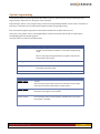
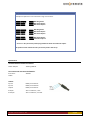
PowerLink Switch OneRemote Type 30012642 User Manual 30012642u3uk Content Standard Application ......................................................................................................................................... 2 Plug & Play ............................................................................................................................................. 2 Installation ......................................................................................................................................................... 3 Special Applications with an IR-receiver Connected ......................................................................................... 4 Option Programming ......................................................................................................................................... 5 www.oneremote.dk Page 1 Standard Application The OneRemote PowerLink Switch is developed for use with active (powered) B&O speakers that can be connected using the Bang & Olufsen PowerLink DIN connectors. The PowerLink Switch makes it possible for two different sound sources to share one set of active PowerLink speakers, especially attractive when the sound sources are not interconnected, e.g. via MasterLink. An example: BeoSound 5 Encore. (B&O Standalone audio product.) BeoVision TV One set of active B&O speakers Plug & Play When correctly installed the PowerLink Switch automatically selects one of the two connected sound sources to be played on the speakers. When using the factory setting (option-2) the sound source most recently powered up is selected. When one or both sources are powered up, the connected speakers are powered up. When none of the two sources is powered up, the connected speakers are powered down. This PowerLink Switch may be programmed for special applications, when an IR-receiver is attached. Note that the IR-receiver is not included as a standard delivery. www.oneremote.dk Page 2 Installation The OneRemote PowerLink Switch is easily installed. 1. 2. 3. Connect the speakers with PowerLink cable(s). Not included. Connect the two sound sources with PowerLink cables. Not included. Connect the mains adaptor. Input 1 Input 2 Outpu t Control IR-in 12 V DC Not used No programming is required for the standard application. The PowerLink Switch is operating in the default setting as described above. www.oneremote.dk Page 3 Special Applications with an IR-receiver Connected The main application for this PowerLink Switch is enabling the alternating use of just one set of active speakers for two separate B&O sound sources. As a default setting the switch detects whenever one of the two sources is powered up, and then directs the signal from this source to the speakers which are powered up simultaneously. For other special applications the PowerLink Switch can be option-programmed, using an external IRreceiver. Basically the PowerLink Switch operates in one of three ways: Switching via IR-control only. Switching to last source powered up. Switching via IR-control too, if an IR-receiver is connected. Switching to source B, if source B is powered up, otherwise source A is selected. (Stop – 2 option). Switching via IR-control too, if an IR-receiver is connected. www.oneremote.dk Page 4 Option Programming The PowerLink Switch may be programmed with different options, determining the way the switching is done. Programming is made only once, during the initial installation. Programming an option is easy. Programming is carried out using the Bang & Olufsen remote control. Therefore an IR-receiver is required to be connected to the PowerLink Switch during programming. Press and hold the programming switch on the PowerLink Switch till the Status LED turns red. Then press a 2 key option code on your Bang & Olufsen remote control within 30 seconds. The Status LED is acknowledging the input by flashing green. The 2 key options are found in the tables below. Status LED During Option Programming Red The programming switch has been activated for more than two seconds, and the PowerLink Switch is in the option programming mode. When in the programming mode the 2 key option code must be entered within 30 seconds. Flashing Green An option has been entered correctly. Flashing Red An error occurred while entering an option. No changes have been made. Green Idle, more than 30 seconds passed without receiving data. 2-Key Option Table q0 Sound source selection is controlled only via an external IRreceiver. Any source key may be used to select one of the two sources. Refer to the IR-source option table below for these options. q1 When one of the two sources is being powered up, the switch directs the sound signal to the speakers. q2 If the source connected to input 2 is powered up, the switch directs the sound signal from it to the speakers, otherwise the sound signal from input 1 is selected. www.oneremote.dk Page 5 2-Key IR-source Selection Table Examples of options for source selection using an IR-receiver. a0 a1 a2 v0 a Will be ignored. a Will select input 1. a Will select input 2. v1 v2 v Will be ignored. v Will select input 1. v Will select input 2. b1 u2 b Will select input 1. u Will select input 2. … and so on. Any source key can be programmed to select one of the two inputs. An option must be entered for every source key used in the set-up. Specifications Included with this PowerLink Switch: Power Adaptor: 12VDC @ 400mA Not included with the PowerLink Switch: IR-receiver: 455 KHz Cables Sockets: Input 1: Input 2: Output: DIN 8-pin PowerLink DIN 8-pin PowerLlink DIN 8-pin PowerLink IR Input: IR output: Jack 3-conductor, 5 volt Jack 3-conductor, not used. www.oneremote.dk Page 6