1
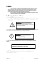
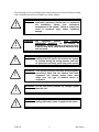
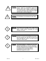
Advanced-High Force Linear Motors User’s Manual 4000 & 5000 Series Linear Motors UM-101 Revision A California Linear Devices, Inc. 2236 Rutherford Road, Ste. 119 Carlsbad, CA 92008 Ph: 760-603-8026, Toll Free: 877-474-2854 Fx: 760-603-0049 2001 e-mail: [email protected] web-site: www.calinear.com UM-101 Revision A Table of Contents: 1. SAFETY: ................................................................................................................... 4 2. WARNINGS, CAUTIONS AND NOTES: ............................................................. 4 3. SCOPE:...................................................................................................................... 7 4. INTRODUCTION: ................................................................................................... 7 4.1. 5. Installation Sequence: ......................................................................................... 8 MECHANICAL MOUNTING: ............................................................................... 9 5.1. Single-Face Mounting:........................................................................................ 9 5.2. Dual-Face Mounting: .......................................................................................... 9 5.2.1. Thermal Growth with Dual-Face Mounting: ............................................ 10 5.3. Coupling to the Load: ....................................................................................... 10 5.3.1. End-Stops:................................................................................................. 11 5.3.1.1. Standard End-Stop (option): ............................................................. 12 5.3.1.2. Threaded End-Stop (option): ............................................................ 13 5.3.1.3. Loads without End-Stops (option):................................................... 13 5.3.2. Trueness of Load: ..................................................................................... 14 5.3.3. Overhung Loads:....................................................................................... 14 5.3.4. Shaft Rotation: .......................................................................................... 14 6. ELECTRICAL CONNECTIONS: ........................................................................ 16 6.1. Motor Drives:.................................................................................................... 16 6.2. Motor Power Connections: ............................................................................... 16 6.2.1. Power Filter:.............................................................................................. 17 6.3. Temperature Levels: ......................................................................................... 17 6.3.1. Thermal Protection (AD590): ................................................................... 17 6.3.1.1. Filtering the VT signal ....................................................................... 20 6.4. Position Feedback: ............................................................................................ 20 6.4.1. Using CLD Position Sensor (optional): .................................................... 20 6.4.2. Using 3rd Party Position Sensor: (optional) .............................................. 20 6.5. Grounding and Shielding: ................................................................................. 20 7. CONTROL CONVENTIONS: .............................................................................. 21 7.1. 7.2. 7.3. 7.4. 8. Directional Reference: ...................................................................................... 21 Cycle Pitch:....................................................................................................... 22 Commutation Reference: .................................................................................. 22 Tuning a Servo System: .................................................................................... 23 MOTOR COOLING: ............................................................................................. 24 8.1. Fan Cooling (option):........................................................................................ 24 8.1.1. Fan Interconnections (option):.................................................................. 24 9. MOTOR CARE AND MAINTENANCE: ............................................................ 24 UM-101 Revision A 9.1. Environmental Considerations:......................................................................... 24 9.2. Bearing Replacement:....................................................................................... 24 9.3. Shaft Care: ........................................................................................................ 25 9.3.1. Shaft Cleaning:.......................................................................................... 25 APPENDIX-A: (REVISION HISTORY) ..................................................................... 26 UM-101 Revision A 1. Safety: The CLD motor is capable of producing high forces and velocities. Always follow appropriate safety precautions when installing and applying these motors. Equipment should be designed and utilized to prevent personnel from coming in contact with moving parts that could potentially cause injury. Read all cautions, warnings and notes before attempting to operate this device. Follow all applicable codes and standards. 2. Warnings, Cautions and Notes: The following conventions are used on the equipment and found in this manual. Please read all equipment labels and manuals before attempting to use CLD Linear Motors. ! WARNING: Identifies information about practices or circumstances that can lead to personal injury, property damage, or loss of life if not correctly followed. A WARNING identifies information that is critical for identifying and avoiding a hazard that could lead to serious personnel injury or equipment damage. ! CAUTION: Identifies information about practices or circumstances that can lead to severe equipment damage A CAUTION identifies information that is critical to prevent permanent equipment damage. NOTE: Identifies information that is critical for successful application and understanding of the product. A NOTE identifies information that is critical for successful application and understanding of the product. UM-101 4 Revision A The following is a list of warnings and cautions that must be observed when working with California Linear Devices High Force Linear Motors. ! ! WARNING: Only those familiar with linear motors and associated machinery should plan or implement the installation, startup, and subsequent maintenance of the system. Failure to comply can result in personnel injury and/or equipment damage. WARNING: This equipment contains HIGH ENERGY PERMANENT MAGNETS. Do not attempt to disassemble. Serious damage to property or injury to person may result. Keep ferrous materials away from the motor. ! WARNING: Improper Servo tuning can cause uncontrolled motion of the CLD motor. Do not allow the system to oscillate during the tuning process, and keep all personnel and body parts away from moving equipment. ! WARNING: This system produces extremely strong magnetic and electric fields that can interfere with other equipment. Use extreme caution when using motor near any type of medical device or equipment. ! ! UM-101 WARNING: Do not use drives powered by voltages greater than 240 VAC. WARNING: Keep fingers and limbs clear of the motor and moving parts when power is applied to the motor. 5 Revision A ! ! WARNING: This system produces very high forces and rapid motion. Under no circumstances should it be operated when hands, fingers or clothing are in, on, or near the motor. Guards should be installed to prevent such items from coming into contact with the motor or other moving parts. WARNING: CLD End-Stops are not designed for large loads. ! CAUTION: Do not move the CLD linear motor’s shaft without proper mechanical End-Stops. It is possible to over travel a motor without End-Stops and cause damage to the motor. ! CAUTION: Do not attempt to insert or realign the shaft into the bearings if has been moved beyond the bearings. If this has occurred, the shaft will be pulled to the stator side and lock in place. The motor must be returned to CLD for repair. ! UM-101 CAUTION: An incorrectly applied or installed motor can result in equipment damage or a reduction in product life. Wiring or application errors, such as under-sizing the motor, using incorrect or inadequate AC supply, or using the motor in excessive ambient temperatures can result in malfunction or permanent damage to the motor. 6 Revision A CAUTION: Poor ground or shield connections or wiring can cause unpredictable motion, and damage the motor, control system or machine. CAUTION: Only use Anderol 465. Other lubricants could break down prematurely and cause permanent damage to the motor. ! ! 3. Scope: This manual provides the necessary information for installation of CLD 4000 and 5000 Series Linear Motor. For technical support, application assistance and sizing information, contact CLD’s Application Engineering at: 760-603-8026, Toll Free 877-474-2854, Fax 760-603-0049, or email to [email protected]. 4. Introduction: The CLD motor is designed to be the driving part of a servo control system. To ensure that the motor performs its function with precision and reliability, it is important to follow the instructions contained in this manual. UM-101 7 Revision A The CLD motor is only one component of a motion system that also includes the load, position measuring device, power regulation device (amplifier) and a system controller. All of these components must be properly specified and working together to achieve optimum system performance and accuracy. Typical Servo System with CLD Motor: Servo Drive Phase A Comand or Program Servo Controller Amp. Control Servo Amp. Phase B Phase C Position Commutation Load C B A Position Sensor Position Commutation Feedback N S N S C N S B N S N S A CLD Motor The CLD motor has several options and accessories that are not addressed in this manual. For detailed technical information on these components, please reference relevant CLD interface control drawings and device manuals. 4.1. Installation Sequence: Use the following sequence when installing a CLD linear motor: 1. Read all of this manual’s warnings, cautions, and notes (Section 1). 2. Properly mount the motor (Section 5). 3. Ensure tight coupling to the feedback device if it is not an installed option from CLD (Section 6.4). 4. Interconnect the motor to the control system (Section 6). 5. Ensure good electrical shielding and grounding throughout the system (Section 6.5). 6. Initialize the motor with the control system (set direction, motion reference and limits) (Section 7.1). UM-101 8 Revision A 7. Attach the load in a manner that does not induce or cause binding when the motor is stationary or moving (Section 5.3). 8. Tune the system for desired performance and accuracy (Section 7.4). 5. Mechanical Mounting: It is important that the mounting of the motor and load are designed to handle the forces created. The mounting needs to allow the motor shaft to move freely while under load without binding or creating additional loading of the bearings. If the mounting is not secure and true, poor motion quality will most likely result. Tolerance information is contained in the CLD motor interface control drawings. 5.1. Single-Face Mounting: When mounting the motor, it is important that the motor mounting face (Datum A), is perpendicular to the direction of motion, and that it maintains this orientation when the motor is under load (Refer to motor ICD for bolt pattern). Shaft Stroke 5.2. Dual-Face Mounting: Dual-Face Mounting can only be utilized without an integral CLD position sensor. When mounting in this fashion, it is important to ensure that shaft motion is perpendicular to the parallel planes of the motor’s mounting faces with and without applied load. It is important to ensure that the linear position-sensing device is tightly coupled and its output is proportional to the shaft’s motion. UM-101 9 Revision A Mounting Surface Mounting Surface Shaft Stroke Shaft Stroke Thermal Growth 5.2.1. Thermal Growth with Dual-Face Mounting: As the steel within the motor heats, the motor will expand. The motor mounting will need to accommodate variation in the motor length that occur with varying temperature. 5.3. Coupling to the Load: The load is typically coupled with the four ¼ -20 threaded mounting holes on the end of the shaft, or with the use of an optional CLD end-stop. It is extremely important that the load is coupled with as little compliance as possible in the direction of force and motion. Poor coupling will result in diminished system performance. Load UM-101 No Compliance 10 Revision A UM-101 11 Revision A Stop Surface ! 5.3.1.1. Stop Surface WARNING: CLD End-Stops are not designed for large loads. Standard End-Stop (option): CLD’s standard end-stop is designed to prevent the shaft from being retracted into the motor. It is not designed for interconnection to a load. This plate is shipped as a standard option on both ends of the motor shaft. When a CLD-supplied feedback device is attached to the motor, an end stop is attached on the feedback side to prevent over-travel. UM-101 12 Revision A 5.3.1.2. Threaded End-Stop (option): The threaded stop option can simplify the connection of the motor to a load. When attaching the load, ensure full thread engagement of the stop and use a locking nut. Follow all other guidelines for attaching loads to the CLD motor. 5.3.1.3. Loads without End-Stops (option): When attaching loads to the end of the shaft without using an end stop, ensure that the stopping mechanism is capable of withstanding the forces exerted by the motor and load. 1. Use four ¼-20 hardened screws with ½ inch of engagement to attach the load to the motor shaft. 2. Ensure a flat flange of 2¼” diameter minimum to extend 1/8” beyond the shaft diameter. 3. Ensure that nothing is protruding inside the flange area that could damage the shaft seal. .125" min. Load UM-101 13 Revision A 5.3.2. Trueness of Load: Loads mounted to the CLD motor must to be mounted so the forces and motion are in line with the shaft. The CLD motor is not designed for offset loads that can cause additional loading or binding of the bearings. Load -B- CL MOTION A -A- B 5.3.3. Overhung Loads: The CLD motor is not designed for overhung loads greater than 25 lbs. Overhung loads cause additional and unpredictable bearing wear. Load 25 Lbs Max. Force 5.3.4. Shaft Rotation: Shaft rotation is only limited by the feedback device and load constraints. The CLD motor shaft has nothing preventing it from rotating. If shaft rotation is not acceptable, provisions need to be taken to prevent the shaft from rotating. UM-101 14 Revision A UM-101 15 Revision A 6. Electrical Connections: Control component and system manufacturers use differing nomenclatures in their wiring conventions. When inserting the CLD motor into a system, be sure to consider this, and carefully examine the CLD conventions and those of the control system manufacturer to ensure proper compatibility. Where applicable, CLD follows conventions established in NEMA ICS 16 and ICS 17 ( ICS 17 is presently being written). Motor current and Motor power need to be limited by the amplifier or drive to not exceed the ratings given by individual specification sheets. Thermal cutout should be employed by the system to ensure that motor does not exceed the maximum rated temperature of the motor. Note: 6.1. It is important to use good grounding and shielding practices for any servo systems that use this motor to minimize electrical interference. Motor Drives: CLD motors require a motor drive system to control the position of the motor. The motors are designed for use with drives powered by 240 V 3ø power. Use sinusoidal servo amplifiers or drives with the CLD motor. The servo drive system should be selected and specified to match the specific application. WARNING: Do not use drives powered by voltages greater that 240 VAC. ! 6.2. Motor Power Connections: It is recommended that a CLD Motor Power Cable be used to connect the motor to the power amplifier or drive. CLD power cables have integrated the necessary power components, connectors and shielding to make a good electrical power connection to the motor. CLD produces a 10 ft. motor power cable (MPC-XX-10-1) and a 25ft motor power cable (MPC-XX-25-1) for use with CLD 4000 and 5000 series motors. Note: UM-101 If cable lengths greater than 25 ft. are needed, additional voltage spike suppression and special cable design will be necessary. 16 Revision A MOTOR FILTER DRIVE A B C 4 5 6 1 2 3 CABLE PHASE A A N B PHASE C C PHASE B D 6.2.1. Power Filter: A common mode choke should be used in series with the motor power leads. This choke will help minimize ground currents associated with PWM amplifiers and drives. The choke presents a high impedance on to capacitively-coupled ground currents from the PWM transitions. The Choke should be placed within 6 inches of the amplifier or drive lugs. These chokes are supplied on CLD motor power cables. 6.3. 4 5 6 1 2 3 1 2 3 6 5 4 Temperature Levels: CLD motors are equipped with temperature sensors to signal the control system when the motor has reached its maximum rated temperature preventing permanent damage to the motor. This motor has no other mechanism that will shut down the motor in the event of over heating. Ensure proper use of the Thermal Protection Sensors with the control system. 6.3.1. Thermal Protection (AD590): The CLD motor’s temperature sensor is an Analog Devices AD590 integrated circuit temperature transducer. The AD590 is a terminal IC that provides an output current proportional to absolute temperature (i.e., the Kelvin scale). This device functions as a high impedance current source. UM-101 17 Revision A The end user will typically provide a fixed voltage source rated at anywhere from 4VDC to 30VDC, and a 10kΩ resistor. The device functions essentially the same at 4V as it does at 30V, thus providing a large degree of flexibility based on the user’s available power source. The CLD linear motor uses two AD590 sensors, one at either end of the motor. Connecting the two sensors as shown in the diagram, allows the two sensed temperatures to be measured. The AD590 simply provides 1 µA/Kelvin. Therefore, 25°C (273.2 + 25 = 298.2K), should give you 298µA (about 0.3 mA). When the 10kΩ resistor is incorporated as in the figure, the 0.3 mA found at room temperature drives the 10k resistor, giving you a voltage drop across the resistor of 3 volts (0.3mA × 10kΩ = 3 V). The Table shows what the user can expect to measure across the 10k resistor of figure as winding temperature increases. The maximum temperature that the sensor should reach is 95°C. In applications where the motor is rapidly climbing in temperature (>5°C/min.) the set point should be lowered by 20°C. Motor (winding) temperature and VT UM-101 Celsius Fahrenheit Kelvin AD590 output (microamps) V T output VDC 25 35 45 55 65 75 85 95 105 77 95 113 131 149 167 185 203 221 298 308 318 328 338 348 358 368 378 298 308 318 328 338 348 358 368 378 2.98 3.08 3.18 3.28 3.38 3.48 3.58 3.68 3.78 18 Revision A TEMP SENSOR CONNECTOR END OF MOTOR SUPPLY 5-30VDC RED + AD590JH ANALOG INPUT TO CONTROL SYSTEM BLACK - 10 KW 0VDC TEMP SENSOR OPPOSITE CONNECTOR END OF MOTOR SUPPLY 5-30VDC WHITE + AD590JH ANALOG INPUT TO CONTROL SYSTEM GREEN - 10 KW 0VDC UM-101 19 Revision A References: AD590 data sheet, Analog Devices: http://products.analog.com/products/info.asp?product=AD590 or http://www.analog.com/pdf/1186_b.pdf 6.3.1.1. Filtering the VT signal A filtering algorithm is typically required to prevent false trips due to noise. One method of filtering is to simply look at the time averaged VT value, and to disable the driver when the average value of VT (over 5 seconds or over some number of servo cycles) exceeds 3.78Vdc. (Example: Use in a servo loop; Vavg=.01(VinVavg)+Vavg ; Start loop with Vavg set to zero) 6.4. Position Feedback: A position feedback signal is required for proper operation of CLD motors. The position feedback signal supplies the control system with the motor’s position for control and commutation. Position sensors other than the CLD sensors can be used. The type of position sensor is a system consideration and needs to be determined during system design. 6.4.1. Using a CLD Position Sensor (optional): CLD produces several position feedback devices for use with its motors: Individual feedback device options have different resolutions, signal types, and compatibility. The Interface Control Drawings for the feedback option contain the relevant information and specifications. [Carefully match the feedback signal types described in the control system manual]. Ensure directionality and commutation compatibility before applying power to the motor. 6.4.2. Using a 3rd Party Position Sensor (optional): When using a position sensor other than one supplied by CLD, it is important to meet the following criteria in addition to those determined during system design: Ø Proportional coupling between motor linear position and output signal. Ø A means of commutating the motor. Ø Tight mechanical coupling between the sensor, motor shaft and motor. 6.5. Grounding and Shielding: It is important that the motor and interconnection cables are well-grounded and shielded. The motor grounding should be to a central system ground as well as to the amp and controller. The motor power cable also needs to be shielded and attached to the central ground. UM-101 20 Revision A CAUTION: ! Poor ground or shield connections or wiring can cause unpredictable motion, and could damage the motor, control system or machine. 3 Phase Power + Ground P 1 Amp Power Motor Power Cable Y Axis Filter Motor Power P 3 Control AMC Amp. P 2 X Axis Motor 7. Control Conventions: When using the CLD motor in a servo system, specific information always needs to be known and accounted for by the control system. The system always needs to have a directionality reference established, where positive direction or force sensed by the feedback device is commanded by the amplifier and control system. A commutation method with a cycle pitch and reference angle must be established. Many feedback devices supply commutation signals, but if they are devices other than one supplied with the motor, a zero reference angle will have to be established with the control system. 7.1. Directional Reference: For the motor and control system to work properly together, a directional reference will need to be established for the system. CLD motors will generate positive force and motion, and cause the shaft to extend on the power connector side of the motor when the 3 phase wave-form below is applied. UM-101 21 Revision A Positive Motion Phase to Null EMF DX Shaft Position (in.) -1.383 -0.922 -0.461 0.000 0.461 0.922 1.383 Phase A BEMF Phase B BEMF Phase C BEMF 180 270 0 90 180 270 0 90 180 270 0 90 180 Phase Angle (deg.) 7.2. Cycle Pitch: As with other sinusoidal brushless motors, the CLD motor is commutated relative to the shaft position within an electrical cycle. The repetition distance of the cycle is known as the cycle pitch. The cycle pitch on the 4000 and 5000 series motors is .922 inches. 7.3. Commutation Reference: When using a sinusoidal brushless motor without a CLD-supplied commutation feedback device, it is necessary to know the relative shaft position at the start of the electrical cycle. CLD motor documentation is supplied with two reference positions (Q max And X0). Q max is a reference commutation angle with the shaft fully extended in the positive direction. X0 is the distance from last zero degree phase position to the position of maximum positive direction. These values are determined UM-101 22 Revision A for each motor at the time of manufacture, and are specific for a motor and shaft combination. These values are listed in the documentation supplied with each motor. Shaft in Qmax position Shaft in X0 position 7.4. Tuning a Servo System: The servo system that includes the CLD motor will likely require some form of tuning. Follow the drive and control system manufacturers recommendations for tuning of the system. ! UM-101 WARNING: Improper servo tuning can cause uncontrolled motion of the CLD motor. Do not allow the system to oscillate during the tuning process, and keep all personnel and body parts away from moving equipment. 23 Revision A 8. Motor Cooling: Motor cooling is an important facet of the motor’s operation. Depending on the load capacity and ambient air temperature, a cooling system may be required. It is important to keep in mind that like any other motor, the CLD motor produces heat when it operates. It must have the opportunity to dissipate this heat or it will eventually overheat and fail. It may dissipate heat through natural convection (natural flow of air), conduction (attaching to a larger cool object), or one of the CLD cooling options. The more heat a motor can dissipate, the cooler the motor will run, and the longer it will last. 8.1. Fan Cooling (option): The CLD motor can be supplied with five fans that force air over the motor and keep it cool. It is important that the fans and the motor are kept clean, and that cool air is allowed to move freely around the motor. Buildup of excessive dirt and debris on the motor’s cooling fins will cause the cooling system to work inefficiently and could lead to overheating the motor. 8.1.1. Fan Interconnections (option): Connect the fan to a 220 VAC single-phase supply for optimum cooling. Fans will run at lower voltages with less than the designed airflow. Follow applicable local wiring codes and regulations for interconnections. 9. Motor Care and Maintenance: It is important to keep the motor clean and free of dirt and chemicals to prevent damage and ensure long motor life. The CLD motor is not designed for wash-down or exposure to most cleaning chemicals. When cleaning the motor, use a clean dry cloth when removing dirt and debris from the motor and shaft. 9.1. Environmental Considerations: The CLD motor is designed for use in an indoor industrial environment. The motor is not designed to be washed down, exposed to weather, corrosive, or abrasive elements. Ambient temperatures should be between 1°C and 30°C (33°F and 85°F). If the motor is to be used in an ambient temperature greater than 30°C (85°F), the motor’s power rating will need to be decreased. 9.2. Bearing Replacement: The CLD motor contains replaceable bearings in the event that they wear out or require replacement for other reasons. The bearings are designed in a taper-lock housing with an integrated oil reservoir. CLD supplies bearing replacement kits containing materials needed to replace both BKM2000. Note: UM-101 Only use bearings contained in the CLD bearing replacement kit for the 4000 and 5000 series motors. 24 Revision A 9.3. Shaft Care: The exterior of the motor shaft is carbon steel that will corrode if subjected to corrosive agents. Take care in keeping it clean and free of contaminates that could cause corrosion. The shaft should be maintained with a thin film of CLD-specified oil only. In corrosive environments, the motor shaft will need to be protected from elements. 9.3.1. Shaft Cleaning: The CLD motor shaft is self-lubricated by oil that is contained in a reservoir in the bearing assembly. Additional oil should not need to be applied to the shaft. If the bearing reservoir runs out of oil, the bearing assembly should be replaced. When cleaning the shaft, use a clean rag lightly oiled with Anderol 465. CAUTION: ! UM-101 Only use Anderol 465. Other lubricants could break down prematurely and cause permanent damage to the motor. 25 Revision A Appendix-A: (Revision History) ECO # Revision 0064 A Change Initial Release Date _ January 3, 2002 26