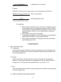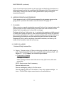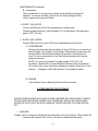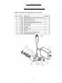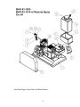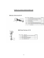
1
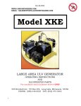
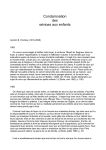
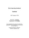
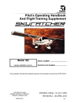
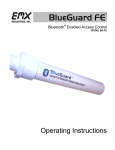
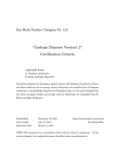
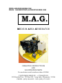
WWW.LONDONFOGGERS.COM
EMAIL: [email protected]
.M.A.G.
MEDIUM AREA GENERATOR
OPERATING INSTRUCTIONS
AND
ILLUSTRATED PARTS
For machines serial numbers above 450268
CUSTOMER SERVICE – A TRADITION
505 Brimhall Ave PO Box 406 Long Lake, Minnesota 55356
PHONE: (800) 448-8525 FAX: (952) 473-5302
Index
Specifications
2
I.
Safety Precautions
3
II.
Operating Instructions
1.
Service Before Start-Up
2.
General Operation
3.
Flow Rates
4.
Calibration
5.
Application Instructions
A: General Instructions
B: Indoor Application
C: Outdoor Application
4
5
8
9
9
9
10
10
Maintenance
1.
Daily or Every Use
2.
Every 25 Hours
3.
Every 100 Hours
4.
Every 200 Hours
10
11
12
12
III
IV.
V.
VI.
Preparation for Storage
Assembly/Installation Instructions
1.
Skid Mounted Units
2.
Wheel Mounted Units
13
14
Illustrated Parts
1.
Basic Machine
2.
Remote Fog On/Off Accessory
3.
Pickup Tube and Nozzle Tip
17
17
18
19
Orifice Disc Chart
21
1
12
SPECIFICATIONS
Type:
Wheel or skid mounted; non-thermal, U.L.V. (Ultra
Low Volume) Cold fog aerosol generator.
Engine:
Fuel consumption:
7 HP, 4 Cycle, Recoil Kohler gasoline.
2 hours run time approx.
Air Pump:
Cast Iron Single Stage; Operating Pressure = 40-85
P.S.I.
Formulation:
Chemical Flow Rate 0-6 oz. /min (0-180 ml. / min)
Nozzle System:
Single, sonic velocity; adjustable 180° azimuth, 0-45°
up elevation.
Tanks:
Formulation: 2.5 U.S. Gallons (9.5 Liters)
Gasoline: 1.05 U.S. Gallons (4.1 Liters)
Particle Size:
80% less than 20 microns
Weight Empty:
95 Pounds (43 Kilograms)
Length:
29 Inches (73.6 cm)
Height:
19 Inches (48.3 cm)
OPTIONAL
Remote 12V On/Off for formulation Flow part # 3-607
50 Ft. Remote Nozzle Retrofit Kit
part # 3-900
Wheel Kit with Handle
part # 3-825
The term U.L.V. is an abbreviation for Ultra Low Volume.
Ultra Low Volume is the designation for the technique of treating
areas with relatively small amounts of chemicals in the aerosol state.
For best results, London Fog ULV Aerosol Generators should be
operated and maintained in compliance with the formulation label
instructions.
2
I. SAFETY PRECAUTIONS
WARNING
READ AND UNDERSTAND THESE SAFETY PRECAUTIONS BEFORE OPERATING
MACHINE.
1.
Engine and Fuel: This machine uses gasoline as the fuel for the internal
combustion engine and all precautions commonly applying to this volatile fuel
should be observed. Exercise extreme caution to avoid spilling of gasoline. If
spillage occurs, wipe it off and allow evaporation time before starting the engine.
DO NOT attempt to put fuel in tank while the machine is still running. Avoid
smoking or open flames in area when handling gasoline. Never run the unit
indoors unless exhaust is vented outside. These fumes contain carbon
monoxide which is Colorless and odorless and can be fatal.
NOTE
DO NOT OPERATE ENGINE WITHOUT MUFFLER.
DO NOT TOUCH HOT MUFFLER, CYLINDERS OR FINS AS CONTACT
MAY CAUSE BURNS.
Except for adjustment, DO NOT OPERATE THE ENGINE IF AIR CLEANER
OR COVER DIRECTLY OVER THE CARBUETOR AIR INTAKE IS
REMOVED.
DO NOT RUN THE UNIT IF THE BELT GUARD IS REMOVED.
DO NOT TAMPER WITH GOVERNOR SPRINGS, GOVERNOR LINKS OR
OTHER PARTS WHICH MAY INCREASE OR DECREASE THE
GOVERNED ENGINE SPEED.
2.
Engine Speed: (rpm) should be checked periodically to ensure that it is
operating correctly, as the engine affects the air pressure and formulation flow
which affects droplet size.
3.
Machine Damage: Never operate a machine after it has been damage. A
damage machine can be very hazardous.
4.
Wind: Spraying during windy conditions is not usually practical because the
formulation will drift out of the intended area. However, under NO circumstance
should spraying into the wind be attempted. This may cause hazardous
accumulations of formulation on the machine or carrying vehicle.
3
SAFETY PRECAUTIONS - Continued
5.
Safety Equipment: In addition to any safety equipment that may be required by
the type of formulation which is being used, the following items should be with
each unit during fogging operations:
a. Fire Extinguisher, chemical type rated for fuel fires.
b. First Aid Kit
c. Eye Wash Solution
d. Safety Glasses
e. Container of Oil Dry Compound
f. Gloves rated for High temperature
g. Respirator adequate for formulation being used.
6.
LABEL: Ensure that formulations are applied only in strict compliance
with the formulation label as well as local, state, and federal regulations. IT
IS THE OPERATOR’S RESPONSIBILITY TO DISCOURAGE ANYONE FROM
PLAYING IN THE SPRAY OR BEING NEAR THE MOVING VEHICLE.
7.
Formulations: Ensure that formulations are applied only in strict
compliance with the formulation label as well as local, state, and federal
regulations and that these formulations are dispersed only by a trained
personnel of public health organizations, mosquito abatement districts, pest
control operators or other qualified personnel.
a. Always comply with any requirements for protective clothing, goggles,
gloves, facial masks, or respirators required on the formulation label.
b. Do not exceed the dosage set forth on the registration label of the insecticide
to be used.
c. Always store formulation in its original labeled container.
IN NO WAY IS IT TO BE CONSTRUED THAT THE CHEMICALS AND/OR DOSAGES
ARE THE RECOMMENDATION OF LONDON FOG, INC.
LONDON FOG, INC. SHALL IN NO EVENT BE LIABLE FOR CONSEQUENTIAL
DAMAGES OR CONTINGENT LIABILITIES ARISING OUT OF THE FAILURE OF ANY
AEROSOL GENERATOR OR PART TO OPERATE PROPERLY.
II OPERATING INSTRUCTIONS
1. SERVICE BEFORE START UP:
A. Engine: See Kohler engine manual provided with machine. Service
engine with gasoline and oil. Check oil level frequently.
4
OPERATING INSTRUCTIONS (Continued)
B. Compressor: Before operating compressor, remove the oil fill plug and
replenish the oil. Oil level should be maintained at the upper mark on the
indicator. Oil level should be checked daily. Use only London Fog
Anderol 500 or Amsoil Synthetic Reciprocating Compressor oil. Do not
use petroleum oil as increased nozzle cleaning and maintenance will
result.
C. Drive Belt: Check drive belt which should be in perfect alignment and
neither excessively tight nor loose enough to slip.
2. GENERAL OPERATION
A. Service the formulation tank with insecticide. Use only insecticide
formulation labeled for the specific application and supplied by a
reputable dealer or distributor.
B. Be sure the aerosol ON/OFF valve is in the OFF position. The aerosol is
turned ON and OFF by setting the handle of the ON/OFF valve to the
proper position. In the ON position, the handle will be positioned straight
up and down, or vertical.
C: Engine Start Up:
DANGER: Always keep hands and feet clear of machinery
5
OPERATING INSTRUCTIONS (Continued)
Choke Engine; Manual choke, move lever as illustrated.
Rewind starter. Grasp starter grip as illustrated and pull out cord
rapidly. Repeat if necessary with choke opened slightly. When
engine starts open choke gradually.
D: To stop engine:
Move stop switch to OFF position.
E: Air Pressure:
It is of the first importance that proper air pressure be maintained. Air
pressure to the air tip should be 40-85 psi as indicated by the green area
of the air pressure gauge. If proper air pressure is not obtained check:
A. Engine should be running at 2500-2800 rpm and air pump at 800900 rpm. A loose slipping belt can cause loss of compressor rpm.
Malfunctioning engine or governor out of adjustment can cause improper
engine rpm.
B. Air leaks can cause reduced pressure even though engine and air
pump are operating OK. Air leak at or around air – fluid nozzle tip or
junction of nozzle with aluminum nozzle body, can cause reduced
pressure. Be sure that the Teflon gasket which seals the mating surfaces
between the fluid nozzle and aluminum nozzle body is in good condition
and properly installed. Be sure that the fluid nozzle is properly tensioned
against the Teflon gasket. Air leaks at any of the line joints can also
cause reduced pressure.
NOTE: If nozzle air pressure is below normal on daily check up, check for
air leaks at all joints between compressor and outlet of aerosol nozzle
assembly. Air leaks can be detected by holding the hand or finger close to
the various joints and feeling if air under pressure is blown against the hand
or finger.
C. Unduly high pressure can be caused by air pump turning in
excess of 900 rpm, which is unlikely. High pressure can also be caused by
plugging up or partial obstruction of the annular outlet air orifice at air – fluid
nozzle tip. Replace air cap with spare if available to check for trouble due to
partially obstructed or damaged air outlet orifice. Also, unduly high air
pressure can be caused by obstruction with foreign matter of air holes in the
aluminum nozzle body.
6
OPERATING INSTRUCTIONS (Continued)
NOTE: To remove the air cap loosen and remove the knurled nozzle ring (see figure M).
Pull the air cap straight out and off of the fluid nozzle. It is not necessary to loosen or
remove the fluid nozzle from the nozzle body when cleaning the air cap.
(Non Remote Nozzle)
If air pressure exceeds normal setting and the engine rpm has not increased
above normal, a partial blockage may have occurred in the air cap of the
aerosol nozzle assembly. To clean air cap (and fluid nozzle when necessary)
use acetone as a solvent for gum or varnish and wipe all surfaces clean with
a rag. Carefully clean the orifice in the air cap with a rag and acetone. Blow
through the orifice with compressed air if available. While air cap is removed,
wipe clean all exposed surfaces of the fluid nozzle. Be sure that any deposit
or build-up is wiped clean form the projecting snout of the fluid nozzle, where
it projects through the center orifice of the air cap.
While the air cap is removed, also inspect the small holes in the fluid nozzle
for deposits or internal build-up. Cleaning of these holes (and removal of the
fluid nozzle) is seldom required due to the large area in relation to the air
flow area through the air cap. To clean the holes in the fluid nozzle, remove
nozzle and clean holes with a toothpick and acetone. Also clean all exposed
surfaces with a rag and acetone. At the same time, clean the circular air
grooves in the back of the fluid nozzle. Blow through the holes with
compressed air, if available.
7
All nozzle assembly parts should be soaked in acetone if necessary to soften
gum, varnish or other deposits.
OPERATING INSTRUCTIONS (Continued)
Use care not to over – tighten the fluid nozzle against its Teflon gasket so as
to avoid extruding or damaging this gasket. Replace Teflon gasket (p/n
1013) if worn or damaged in any way.
3. FLOW RATES
Rate of formulation flow is controlled by metering orifice located in the fitting at
the top of formulation tank. (See figure o)
A. Orifice Disc System
The orifice disc should be placed inside the filter/orifice chamber which is
located in the outlet of the formulation tank. (see figure O)
a. To remove or change an orifice disc, first use (2)13/16 wrenches (one
to hold the tank fitting, and the other to unscrew filter/ orifice chamber
nut) then remove nut and fluid line, then hold the smaller hex nut
using a wrench and loosen the hex retainer nut and another 13/16
wrench to hold tank fitting.
b. Several sizes of orifice discs are shipped in the small container
attached to the base frame next to the formulation tank (see figure O).
The discs are marked with the orifice hole size. A chart of
approximate flow rates vs. orifice sizes when using formulations with
a viscosity similar to that of carrier oils such as kerosene, mineral oil,
diluent oils, Etc.is located in the back of this manual.
8
c. Using a smaller orifice size will reduce the formulation flow rate and
produce a smaller particle size or “dryer” aerosol.
OPERATING INSTRUCTIONS (Continued)
Using a larger orifice size will increase the formulation flow rate or
keep the flow rate the same when using a more viscous material.
NOTE: DO NOT USE METAL OBJECTS TO CLEAN ORIFICE OR
SCREEN FILTER
4.
CALIBRATION
Since the nozzle used is an external mix siphon (suction) type nozzle,
calibration must be made with the machine running.
A. Disconnect the white nylon nut and fluid line from the nylon elbow fitting
attached to the filter/orifice chamber.
Use (2) 13/16 wrenches (one to hold the tank fitting, and the other to
unscrew filter/ orifice chamber nut.
With the machine running, using a stopwatch and graduated beaker and
measure the flow for (1) minute and measure the amount of fluid used.
Repeat for accuracy.
NOTE: Care should be taken not to have the graduated beaker higher
than the top of the formulation tank, or lower than the bottom of the
formulation, as this will affect the accuracy of the calibration.
5. APPLICATION INSTRUCTIONS
A. General Instructions:
a. Read, understand, and follow chemical labels instructions.
b. Use only chemicals that are labeled for your specific application.
c. Always use protective clothing and a respirator that is adequate
for the chemical and particle size being aerosolized.
d. Do not start formulation flow unless proper air pressure (40-85)
psi is obtained. When using Malathion, allow engine and
compressor to run for several minutes after start up from cold
condition, before turning chemical ON.
e. To determine the application time, first determine the total
amount of formulation to be used. Always follow label
language.
(cu ft of area to be treated) (oz of formulation req’d per 1000 cu ft) = oz. of
10000
formulation
9
oz. of formulation
calibration flow rate in oz/min
= application time in minutes
Example:
A 50,000 cu ft area is to be treated using 1 oz of formulation per 1000 cu ft.
(50,000 cu ft) (1.0 oz/1000 cu ft) = 50 oz of formulation
10000
50 oz
= 25 Min Application Time
2 oz/min (calibrated flow rate)
B. Application
a. Best results are obtained in the cooler hours of early morning or
evening when there is a temperature inversion and the insects
are most active. Ideal wind speed is between (3-7) mph. If wind
speed exceeds (10) mph, it is not recommended to disperse
insecticide.
b. Spray upwind of the area to be treated.
c. If the area to be treated is over 300 feet deep, move downwind
approximately 300 feet on each successive pass.
d. Do not spray automobiles or buildings; with some insecticides,
paint damage may result.
III. MAINTENANCE
1. DAILY OR EVERY USE
A. Compressor
Check oil level monthly. Oil level must be to the top mark on the oil indicator. Use
only London Fog Anderol 500 or Amsoil Synthetic Reciprocating Compressor Oil.
Do not use petroleum oil.
B. Engine
Check oil level daily. Oil level must be to the top of the fill hole. Pay particular
attention to the engine requirements to change the oil after the initial (5) hours of
running time. For oil type see Service Before start –up, section III-1 A.
C. Belt
Check drive belt which should be in perfect alignment and neither excessively tight
or loose enough to slip.
D. INSECTICIDE/AIR DISCHARGE NOZZLE
10
MAINTENANCE (continued)
Check to see that knurled nozzle ring is finger tight and that the fluid nozzle hex is
tightened properly so that the nozzle seats air tight against the Teflon gasket and
nozzle body. Check for air leaks at Teflon gasket with air pump running but
insecticide turned off.
E. NOZZLE OPERATING AIR PRESSURE
Check pressure to air tip (40-85) psi as measured by air pressure gauge on the
gauge panel. If pressure is incorrect, consult section III-2 E, page 10.
F. FLUSHING
When corrosive or caustic insecticides are used, flush out the chemical system with
soap and water or other suitable flushing fluid after each time chemical is used.
Always flush thoroughly prior to down time or storage.
Flushing out the lines, fluid nozzle, etc., is carried out by passing a suitable amount
of flushing fluid (soap and water or other recommended fluid) through the machine,
just as in normal operation. To drain or clean formulation tank, remove fluid line by
disconnecting line and nylon nut from elbow fitting and lift tank from tank wrap.
Dispense all fluid or remove and dump formulation container, and then dry the
inside of the formulation tank with a clean rag.
2. EVERY (25) HOURS
Perform all Daily functions Plus:
A. Engine: Change engine oil. Remove drain plug and drain oil while engine is
warm. Replace plug and fill with oil as specified in Service Before Start – UP,
Section III – 1 A. Oil capacity is in Kohler Engine Manual.
a. To service Air Cleaners
Cartridge Air Cleaner
Clean cartridge at three month intervals or every (25) hours, which ever
occurs first.
NOTE: Service more often if necessary
Remove knob and cover.
Remove cartridge by pulling it off of the screw.
Clean by tapping gently on a flat surface. If very dirty, replace cartridge
clean. Follow Kohler engine manual service recommendations.
11
or
MAINTENANCE (continued)
B. Compressor
The air intake filter in the air pump cylinder heads should be cleaned or
replaced. To remove air filters, remove the two bolts holding the filter
cover in place and remove the filters.
3. EVERY (100) HOURS
Perform all Daily and (25) Hours maintenance functions plus:
Change engine spark plug. Use Champion CJ-8 or equivalent. Set spark plug
gap at .030” (.76 mm).
4. EVERY (200) HOURS
Perform Daily (25) hours and (100) hours maintenance functions plus:
A. COMPRESSOR
Change air pump crankcase synthetic oil every 200 hours, or sooner if oil
becomes dirty. Use London Fog Synthetic Reciprocating Compressor Oil
Anderol 500 or Amsoil Reciprocating Compressor Lubricant may be
used. Do not use petroleum oil, as it will increase nozzle build up and
pressure increase.
NOTE: For sources of London Fog part number 3-203 (Oil 1 Qt.
Synthetic), Anderol 500 or Amsoil Synthetic Reciprocating Compressor
Oil, contact the London Fog factory (telephone number at the front of this
manual). Change air intake filter element, if not replaced earlier.
B. ENGINE
Follow Kohler Service Manual included with this manual.
IV. PREPARATION FOR STORAGE
NEVER STORE ENGINE WITH FUEL IN TANK INDOORS OR IN ENCLOSED, POORLY
VENTILATED ENCLOSURE WHERE FUEL FUMES MAY REACH AN OPEN FLAME,
SPARK OR PILOT LIGHT AS ON A FURNACE, WATER HEATER, CLOTHES DRYER,
ETC.
1. MACHINE
Prepare unit for storage by draining all the formulation form the container. Then partially fill
container with range oil (#1 fuel oil), kerosene or deodorized kerosene,
12
PREPARATION FOR STORAGE (continued)
or mineral seal oil. Flush system by operating unit until the above base oil is
consumed. Finally drain any remaining base oil from the container.
2. ENGINE
IF engine is to be stored over 30 days, prepare for storage as follows:
A. Remove all gasoline from fuel tank to prevent gum deposits from forming on
these parts and causing possible malfunction of engine.
B. Drain fuel into approved container outdoors, away from open flame.
C. Run engine until engine starts to falter, the use choke to continue engine
operation until all fuel in tank and carburetor is exhausted.
D. Remove the spark plug and pour approximately 1/2 oz (15cc) of engine oil
into the cylinder and turn the engine over by hand, slowly, several times.
Replace the plug.
WHEEL KIT ASSEMBLY & INSTALLATION INSTRUCTIONS
1. SKID MOUNTED UNITS
Use the wooden base on which machine was shipped, or fabricated wooden
mounting base frame to suit. Secure wooden base to vehicle bed, or frame to
vehicle securely. Use heavy duty bolts.
2. WHEEL MOUNTED UNITS
a. Remove the wooden shipping base from the machine.
b. Mount the two swivel casters attached to the caster mount plate to the mount
flange on the compressor end of the machine using the (2) 5/16 – 18 x ¾
hex head bolts, nuts and lock washers provided.
Next remove formulation tank by unscrewing white nylon nut from outlet
fitting at top of tank and removing tank from tank retainer, allowing access to
rear caster mount plate holes; use 1/4 - 20x3/4 flathead screw, lock washer
and nut.
Next remove (4) screws and remove belt guard, allowing access to caster
mount plate bolt hole and install 1/4 – 20x3/4 hex head bolt, nut and lock
washer provided.
13
ASSEMBLY INSTRUCTIONS (Continued)
C. At the engine end of the chassis, mount an axle/handle bracket assembly on
each side of the chassis. The handle pivot pins on the bracket should be located
in toward the engine. The flare out portion of the bracket should be oriented
towards the operator end of the machine. See figure B. Fasten the brackets to
the chassis by inserting the (2) 1/4 – 20X 3/4 bolt through each bracket and the
chassis. Fasten in place using lock washers and nut provided. Tighten firmly.
14
D. Push the axle through both of the axle/handle bracket assemblies and place a
spacer (provided in parts envelope) onto each end of the axle. Slide a wheel
onto each end of the axle and fasten in place by driving the axle hubs onto the
axle. See figure C.
E. Unpack the handle assembly. Using the bolts provided in the large handle
section, mount the smaller top part of the handle to the larger bottom part (see
figure D). Tighten wing nuts to hold in place.
15
F. Hold the handle assembly approximately straight up and down with lower
curved portion pointing towards the air pump end of the machine.
Place one end of the handle over a handle pivot pin (see figure E). Pull the
lower handle ends together and place other handle end over the opposite
handle pivot pin.
Lower the handle into a normal walking position until the handle lock pins snap
into the axle/handle brackets.
16
VI. ILLUSTRATED PARTS
REMOTE NOZZLE EXPLODED VIEW
17
(See Next Page for Item Disc. and Part Number)
18
Item #
1
2
3
4
5
6
Part #
3-404
3-406
3-681
3-675
3-307
3-205
7
8
9
10
11
12
13
14
15
16
17
18
19
20
3-309
3-308
3-405
3-710
3-700
3-209
3-207
3-212
3-316
3-315
3-702
3-200
3-100
3-214
Description
Alumin. Base Frame Weldment
Tank Wrap
Pressure Gauge Panel Only
Pressure Gauge Complete w/ Panel
Alum. Nozzle Body, Manual On Off Nozzle
90 Deg. Brass Elbow / SPECIFY
3-205 Specify remote or manual nozzle, and or Air
Filter
1/2 NPT Ball Joint Female Swivel Fitting
Elbow Brass 64 deg. Welded
Belt Guard Assembly
Tank Cap
Formulation Tank with Cap
Tee Weldment 3 port (pressure release)
Coupling Weldment (form tank to nozzle)
Pressure Relief Valve
Brass Fitting for on off valve 45 degree
On Off valve for Mag Nozzle
Welded Pickup Tube Assy Complete w/ Jaco
Compressor MAG
Engine 7HP Kohler
Copper Pressure Line
19
Quantity
1
2
1
1
1
1
1
1
1
1
1
1
1
1
1
1
1
1
1
1
NOZZLE TIP & PICKUP TUBE EXPLODED VIEW
20
ORIFICE DISC CHART
(see item #3 on MAG PU Tube Assy on Prev Page for orifice location)
NOTE: To order replacement orifices or orifices not listed, use part number # 3802 -xx for desired size.
Example: 3-802-14 = .014 diameter hole, 1 ounce disc or
3-802-51 = .51 disc or 6 ounce disc, .51 diameter hole
Chemical formulations with “thin” viscosity carrier oils such as kerosene,
mineral oil, diluent oils, Etc.
* Oz/Min
Orifice Disc #
1
====.
14
2
====.
22
3
====.
29
4
====.
39
6
====.
51
* These are approximate settings. Always calibrate in order to obtain true
flow rates.
21