1
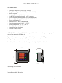
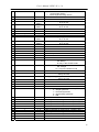
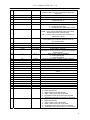
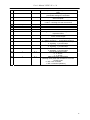
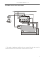
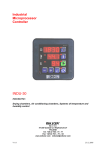
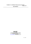
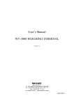
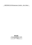
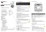
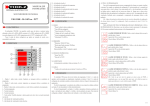
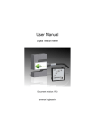
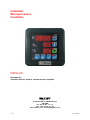
Industrial
Microprocessor
Controller
INDU-20
Intended for;
Vacuum devices, mixers, vacuum control systems
Sp. z o.o.
41-250 Czeladź ul. Wojkowicka 21
POLAND
Tel. +48 32 763 –77– 77,
Fax: +48 32 763 –75 –94
www.mikster.com [email protected]
v.1.0
23.12.2005
User’s Manual ‘INDU-20’ v 1.0
LIST OF CONTENTS
LIST OF CONTENTS......................................................................................................................................... 2
ACTIVATION .................................................................................................................................................... 4
OPERATING PANEL ........................................................................................................................................ 4
INFO MODE....................................................................................................................................................... 5
AUTOSTART MODE ........................................................................................................................................ 5
START MODE ................................................................................................................................................... 6
FUNCTIONS OF RELAYS ................................................................................................................................ 6
GOVERNOR OF THE „TEMPERATURE APPROACH”................................................................................. 6
SELECTION OF SETTINGS OF THE PID GOVERNOR ................................................................................. 7
SERVICE FUNCTIONS ACCESSIBLE FOR THE USER ................................................................................ 8
ALARMS............................................................................................................................................................ 9
CONTROLLER SETUP ..................................................................................................................................... 9
EXAMPLE OF APPLICATION* ..................................................................................................................... 13
NOTES.............................................................................................................................................................. 14
2
User’s Manual ‘INDU-20’ v 1.0
TECHNICAL DATA
-
1 analogue input PT-100 (PT-500, PT1000)
Temperature range: -30.. +400 °C (resolution 0.1 °C)
4 relay outputs
1 analogue output (0,4..20 mA)
1 x RS-485 communication with a PC computer
2 control inputs (alarm signaling or keyboard lockout)
Power supply 230 optional: (110)(24) ± 10% VAC
Power consumption 3 W
Protection level IP65 (from the front)
Operation temperature –10 °C .. +55 °C
Storage temperature –15 °C .. +60 °C
Overall dimensions 134x134x65 mm
Assembling hole 90x90 mm
Internal vacuum sensor
AUTOSTART: according to RTC, with the possibility of an advanced programming (up to 10
days) of the controller switching on.
Types of the temperature control: 2 types of bistable governors and the PID governor
Ending of the process can be done either by the set time or manually.
Recording of the set and measured values, approximately 100,000 recordings*.
65mm
134mm
134mm
80mm
Assembling hole 90x90mm.
* recording module, R- version
3
User’s Manual ‘INDU-20’ v 1.0
ACTIVATION
After the mains are connected the controller is automatically activated. After the welcoming
words the device displays in turn: current hour and minute, measurement in channel 1 –
vacuum in %, set value of the rotational speed of the drum. Three horizontal lines indicate the
lack or failure of a measuring element. Diodes on the keys signal the mode of the device (e.g.
editing or autostart mode). Horizontal lines at the left side of the displayed measured value
signal the governor’s mode: controlled output causes that the diode lights. Diodes on the keys
indicate the controller’s mode. Possible modes of operation are: AUTOSTART, START,
INFO and EDIT.
In the STOP mode, when the START mode ended, the word „STOP” is displayed on the
screen – instead of an hour and minute.
NOTE: in the case of power failure the controller remembers the mode of operation and
returns to this mode at the power supply restart. (unless the time set in the 48 Setup cell
expires).
OPERATING PANEL
RTC clock
Process time
Negative
pressure value
Rotational
speed – set
value
Key of the
AUTOSTART
mode
Key of the
INFO mode
Key of the
START mode
4
User’s Manual ‘INDU-20’ v 1.0
EDIT MODE – CHANGING OF THE SET VALUES
In order to enter the mode of editing the set parameters of the process the key should be
pressed.
Entering into the edit mode is indicated by pulsation of the diode on the key
EDIT.
Keys
are used for correction of parameters. Parameter being edited is
pulsating, confirmation and proceeding to the next editing field is done by the OK key.
Consecutive pressing of the key
means exit from the editing mode.
.
The set parameters are consecutively:
- START mode duration (number of hours and minutes)
- Negative pressure – set value
- Rotational speed – set value
INFO MODE
Single pressing of the INFO key causes the display of information in dependence of the
controller’s mode of operation:
For the AUTOSTART mode
Depending on the parameter in the 47 Setup cell:
At selecting HMD – hour, minute and twenty-four hours delay before the START mode
commences,
At selecting HM – number of hours and minutes remaining to the START mode
Consecutive information, for all modes, are the same:
- Temperature measurement: the upper display shows the current temperature measurement
in channel 1, the lower reads TE,
- The upper display shows PSET, the middle one the negative pressure (set value), the
lower display indicates the rotational speed of the drum.
- Current date: starting from the upper display - one can read the year, month and day.
- Current time: starting from the upper display - one can read hour, minute and second.
Proceeding into the next (previous ) information can be done by keys
.
To exit
the INFO mode the INFO key should be pressed again.
AUTOSTART MODE
The autostart mode is used for entering the START mode with a time delay.
Pressing the AUTO/START key causes transition to the parameters editing of this mode.
There are two possibilities of setting the moment of the controller AUTOSTART:
1. Activation at the predetermined hour and minute – with the possibility of adding the
twenty-four hour delay (F47 SETUP - HMD).
2. Activation after the predetermined number of hours and minutes (F47 SETUP - HM)
To exit the AUTOSTART mode the AUTO/START key should be pressed again.
There is also a possibility of a direct transition from the AUTOSTART into the START
mode. Single pressing of the START key is needed.
5
User’s Manual ‘INDU-20’ v 1.0
START MODE
When all set parameters are introduced (see: EDIT MODE – CHANGING OF THE SET
VALUES) the process can begin, which means the controller should be in the START mode.
Beginning and ending of the START mode is done by pressing the key:
.
For the typical settings of the controller, entering the START mode activates governors and
the countdown of the process time starts.
The display shows the number of hours and minutes remaining to the end of the process.
The end of the process is indicated by the internal sound signal of the controller and by
controlling of the relay output REL5 (unless it is declared in the SF81 Setup as the
temperature governor).
Pressing the OK. key switches off the sound signal.
FUNCTIONS OF RELAYS
REL 2: is responsible for the increase of the negative pressure and the pump controlling
(governor: simple hysteresis).
REL 3: is responsible for the decrease of the negative pressure (governor: reversed
hysteresis).
Controlling of the aerating valve.
REL 4: controlled in the START mode.
REL 5: temperature regulation or alarm event signaling.
GOVERNOR OF THE „TEMPERATURE APPROACH”
Temperature
Tz
Tza
Dout
Parameters
Tz – set temperature value
Tza – temperature of the
governor activation; up to
this temperature the output
is controlled (heating).
When this temperature is
reached the governing
algorithm starts.
Dout – state at the digital
output (high state
corresponds to the heaters
being ON).
6
User’s Manual ‘INDU-20’ v 1.0
SELECTION OF SETTINGS OF THE PID GOVERNOR
To obtain an access to the settings of the PID governor coupled with the particular
measuring channel the MINUS key should be pressed and held and then the INFO key. If the
temperature governor is selected on the relay (REL 5) the upper display shows the
information that the governor can be adjusted – the OK key should be pressed. The edition of
the selected parameter is being done on the middle display (pulsating value). Increasing of the
parameter’s value can be done by the PLUS key, while decreasing by the MINUS key.
Proceeding to the next parameter and confirmation of changes is done by pressing OK. Exit
from the edition mode - by pressing the EDIT key.
Regulation is being done on the bases of:
To – sampling period,
Pr – amplification of the proportional element,
Ti – integration constant (doubling time),
Td – differential constant (advancing time),
TS – set temperature,
Writing 0 value for the integrating or differentiating element causes its switching off. Due
to that feature, it is possible to obtain the arbitrary governing algorithm.
7
User’s Manual ‘INDU-20’ v 1.0
SERVICE FUNCTIONS ACCESSIBLE FOR THE USER
Cell number
UF0
Description
Setting of the real time clock.
Next parameter is reached by the OK. key.
UF1
Change of the access code for the user
Range 0..9999
For 0 value – checking of the access code is switched off
UF2
Information concerning the current program version
UF3
Switching ON/OFF of the keyboard click
OFF – switching off
ON – switching on
To enter the user’s mode the MINUS key should be pressed and held, the PLUS key should
be pressed and held. Those functions are accessible when the access code is given. The access
code is introduced by
keys.
To switch off the checking of the access code its value should be set as zero.
As a rule the access to the user’s settings is switched off.
8
User’s Manual ‘INDU-20’ v 1.0
ALARMS
Controller INDU 20 signals 11 alarm events:
-
Err 1
Err 2
Err 3
Err 4
Err 5
Err 6
Err 7
Err 8
Err 9
Err 10
Err 11
Failure of the internal sensor of negative pressure,
Failure or lack of the measuring element in the channel 1 (temperature),
Permissible MAX negative pressure exceeded,
Permissible MAX temperature exceeded,
Permissible MIN negative pressure exceeded,
Permissible MIN temperature exceeded,
Alarm from the control input 1,
Alarm from the control input 2.
The first step in an alarm activation is the setting of the time delay [seconds] in SETUP (cells
71..73) between an alarm event and the alarm activation. Then the activation of the selected
alarms in SETUP (cells 60..70) should be done.
Alarms are signaled on the display by the word Err with the adequate number, by internal
howler, and - when in Setup cell 81 the relay REL 5 is in the mode of alarm signaling - by
controlling of its output.
Alarm should be confirmed by the OK. key. If the cause of an alarm is not removed, the
controller – after the time delay of the alarm activation - will again signal the alarm.
CONTROLLER SETUP
To enter SETUP the MINUS key should be pressed and held, then the EDIT key pressed.
After providing the access code - the correction of the controller’s parameters can be done.
NR
0
1
DEFAULT VALUE
1
0
RANGE
0..99
0..4
2
1
0..12
DESCRIPTION
Address in the MODBUS network
Transmission rate
0 – 9600
1 – 19200
2 – 38400
3 – 57600
4 – 115200
Type of the measuring input for channel 1
0 – PT-500
1 – PT-100
2 – PT1000
3 – 0..20 mA*
4 – 4..20 mA*
5 – termocouple s**
6 – termocouple b**
7 – termocouple r**
8 – termocouple t**
9 – termocouple j**
10 – termocouple e**
11 – termocouple k**
9
User’s Manual ‘INDU-20’ v 1.0
12 – termocouple n**
current input version
termocouple servicing version
-99,0 ..
Value corresponding to 0 mA for channel 1
for 0..20 mA
999°C
-99,0 ..
Value corresponding to 20 mA for channel 1
for 0..20 mA
999°C
-99,0 ..
Value corresponding to 4 mA for channel 1
for 4..20 mA
999°C
-99,0 ..
Value corresponding to 20 mA for channel 1
for 4..20 mA
999°C
Temperature correction for channel 1
-20 .. 20°C
On / Off
Negative pressure governor:
Off- always
0n-only in the START mode
On / Off
Temperature governor:
Off - always
0n - only in the START mode
0..99%
The lowest negative pressure value, which could be
set by the user
0..99%
The highest negative pressure value, which could be
set by the user
0..3
Temperature governor coupled to relay REL 5
0 – simple hysteresis
1 – reversed hysteresis
2 – approaching hysteresis
3 – PID
0 .. 5
Lower hysteresis for the governor coupled to REL 2
0 .. 5
Lower hysteresis for the governor coupled to REL 3
0 .. 5
Lower hysteresis for the governor coupled to REL 5
0 .. 5
Upper hysteresis for the governor coupled to REL 2
0 .. 5
Upper hysteresis for the governor coupled to REL 3
0 .. 5
Upper hysteresis for the governor coupled to REL 5
Set temperature
-99..999°C
*
**
3
4
5
0
6
100
7
8
9
10
11
0
12
100
13
14
15
16
17
18
19
20
0
On
21
On
22
23
0
24
99
25
26
27
28
29
1
30
31
32
33
34
35
36
37
38
39
40
1
0
1
0
1
1
50°C
-
10
User’s Manual ‘INDU-20’ v 1.0
41
20°C
0..99°C
42
43
44
1
0..100 s
45
46
1
0..1
47
HMD
HMD / HM
48
5
0..10 hour
49
50
51
52
1
1
°C
1 [min]
1..360 min
1..360 min
°C / F
0..99 [min]
53
1
0..1
54
55
56
57
58
59
60
99
150°C
0
-99°C
Off
0..99%
-99.. 999°C
0..99%
-99.. 999°C
On / Off
61
62
63
64
65
66
67
68
69
Off
Off
Off
Off
Off
Off
On / Off
On / Off
On / Off
On / Off
On / Off
0..4
70
Off
0..4
Temperature of activation (Tza) of the governor
coupled to REL 5 for the „ temperature approach”
algorithm
Time delay of the governor [seconds]
coupled to REL 5
Recording
0 – continuous recording
1 – recording only in the START mode
AUTOSTART mode – parameters’ format
HMD – hour, minute and twenty-four hours delay
before the START of the process
HM – number of hours and minutes remaining to
the START mode
Maximal time (in hours) after which (when there was a
power failure) the controller does not return to
the START mode
Rate of the measurements recording
Rate of alarms recording
Temperature unit
Sound signal - duration.
Note! When 0 value entered, the signal can be deleted
by the OK key!
Alarm output mode of operation
0 – interrupted signal
1 – continuous signal
Maximal permissible negative pressure (alarm)
Maximal permissible temperature (alarm)
Minimal permissible negative pressure (alarm)
Minimal permissible temperature (alarm)
Alarm activation – failure of the negative pressure
sensor
Alarm activation – failure of the temperature sensor
Alarm activation - Max negative pressure exceeded
Alarm activation - Max temperature exceeded
Alarm activation - Min negative pressure exceeded
Alarm activation - Min temperature exceeded
Control input 1
0 - alarm switched off
1 – alarm, when inputs 6-8 shorted
2 – alarm, when inputs 6-8 not shorted
3 – keyboard lockout when inputs 6-8 shorted
4 - keyboard lockout when inputs 6-8 not shorted
Control input 2
0 - alarm switched off
1 – alarm, when inputs 7-8 shorted
2 – alarm, when inputs 7-8 not shorted
3 – keyboard lockout when inputs 7-8 shorted
4 - keyboard lockout when inputs 7-8 not shorted
11
User’s Manual ‘INDU-20’ v 1.0
71
60
0..999 s
72
60
0..999 s
73
60
0..999 s
74
0
0..9999
75
76
77
78
79
1
-99..100
80
0
0..99
81
0
0..1
82
1
0..1
83
1
0..1
84
1
0..1
85
1
0..1
86
1
0..1
Time delay in the alarm signaling, when sensors are
faulty
Time delay in the alarm signaling, when the
permissible settings are exceeded
Time delay in the alarm signaling, when there is an
alarm on inputs
Change of the access code to SETUP
0 value – checking the code switched off
Negative pressure offset for the governor
coupled to REL2
Set speed value corresponding to 20mA
on the current output
Mode of operation of the REL5 relay :
0 – alarms signaling, 1 - temperature governor
Response to alarm: measuring sensors faulty
0: signaling, 1: process stops
Response to alarm: settings exceeded
0: signaling, 1: process stops
Response to alarm from the control input
0: signaling, 1: process stops
Type of the current output:
0: 0..20 mA
1: 4..20 mA
State of the relay output REL3
(aerating valve) when the controller is not in the
START mode
0: REL3 not controlled
1: REL3 controlled (aeration)
12
User’s Manual ‘INDU-20’ v 1.0
EXAMPLE OF APPLICATION*
14
PORT1
(RS-485)
30
POWER
SUPPLY
28
* The example of application should give the user a general idea only, and can not be
considered the project of the control system - neither as total nor as its part.
13
User’s Manual ‘INDU-20’ v 1.0
NOTES
14
User’s Manual ‘INDU-20’ v 1.0
NOTES
15
User’s Manual ‘INDU-20’ v 1.0
NOTES
16