1
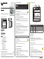
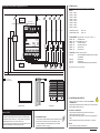
Leader Light s.r.o.
M.Gorkeho 33
SK-052 01 Spisska Nova Ves
Slovakia
www.leaderlight.eu
USER MANUAL
LL REL8 - Relay Output module
01 SAFETY INFORMATION
02.2 Product description
DIP
settings
WARNING!!!
Carefully read before installing, powering or servicing. Nothing to
do if anything misunderstand! Installation can be done only by a
qualified professional in accordance with relevant local codes.
Control data
6pin line conector
LL08 100
D- D+
01.1 Safety instructions
All dimensions are in millimeters
73,5
107
105,4
75,4
01.2 Operating restrictions
Package includes:
- LL REL8
1 pc.
- User manual
1 pc.
Additional items needed:
- Data and power cables
- 24V DC power supply
Content:
01
SAFETY INFORMATION
01.1 Safety instructions
01.2 Operating restrictions
01.3 Fire protection
02
PRODUCT SPECIFICATION
02.1 Technical specification
02.2 Product description
03
INSTALLATION
03.1 Unpacking
03.2 Physical installation
03.3 Connection
03.4 Installation factors
03.5 DMX channels
04
MAINTENANCE AND SERVICE
ENVIRONMENTAL PROTECTION
Do not throw away the appliance with the normal household waste at the end of
its life, but hand it in at an official collection point for recycling. By doing this, you
help to preserve the environment.
©MMX - Leader Light – All right reserved
- This product was designed for indoor use only!
- If the product has been exposed to drastic temperature fluctuation (e.g. after
transportation), do not switch it on immediately. The arising condensation
water might damage your unit. Leave the unit switched off until it has
reached room temperature.
- Do not operate the product in humid, dusty or too hot/cold environments.
- Before connecting, make sure the product is not damaged, wet, or otherwise
damaged.
- Unprofessional operation creates the most damages!
- For transport use the original packaging.
1234
x100
x10
x1 +24V 0V
DIP
CHANNELS
MODE & ADDRESS
POWER
INPUT
D P
A O
T W
A E
R
LL REL8
- Shut down power before installation or maintenance of equipment or
voltage /data source.
- Do not modify, alter, or attempt to service the LeaderLight appliance. Doing
so will void the warranty.
- Use only the recommended DC voltage source.
- Connect the ground to the bottom of the box!
- Electrical connections, service and maintenance can be performed only by
qualified professional.
- AC power supply of DC power supply must comply with local regulations.
- AC power supply must be protected against overvoltage and short circuits.
COMPLIMENTS ON YOUR PURCHASE!
D- D+
DMX 512
RS 423/232
DC 24V
power
Rotating DIP
Control
LEDs
“100““10“ “1“
Made in EU
Leader Light s.r.o. Slovakia, 2010
www.leaderlight.eu
[email protected]
S/N
DC 24V INPUT, Tmax:40°C
2A MAX FOR EACH CONTACT
REL1
REL2
REL3
REL4
S
C
REL5
O
REL6
REL7
REL8
CSOCSO CSOCSO CSOCSO CSOCSO
8x Relay output
4x 6pin line conector
Indication of control LEDs (LED power- green,LED data - yellow)
LED
Indication
Status
LED Power
blinking - 2Hz
O.K. - device is working correct
LED Data
not lit
No DMX signal
LED Data
blinking - 4Hz
O.K. - Connected the correct DMX signal
LED Data
fast blinking
ERROR - incorrect digital signal
LED Power &
LED Data
alternating
blinking
function AutoTest
03 INSTALLATION
Operate only with 24V DC stabilized source!
01.3 Fire protection
- Follow all safety restrictions.
- Device never cover – the minimum space around the vents must be at least
100mm (4 in.).
- Allowed maximum ambient temperature is 40°C (104°F).
02 PRODUCT SPECIFICATION
02.1 Technical specification
Power connection:
Output:
Control data:
Ambient temp. (Ta):
Net weight:
Dimensions LxWxH:
Installation:
DC24V max. 10W
8x relay with make-and-break contacts 2A, real / inductive load
Protocol USITT DMX-512 or RS 423/232 LL defined protocol
0°C ÷ +40°C
0,36 kg
107mm x 105,4mm x 73,5mm
standard DIN installation TS35 – 6DIN
Edition: A - 2010
03.1 Unpacking
- Unpack carefully.
- This is electronic equipment and should be handled carefully.
- Damaged delivered package or if are any mechanical parts broken – it must
be claim immediately by the transport company. Photo pictures as evidence
are valuable for future claim.
03.2 Physical installation
- Loading capacity of bearing area has to be at least 10 times the weight of all
device clusters.
03.3 Connection
-
Respect all SAFETY INFORMATION 01!
Connect the ground (earth) to the bottom of the module!
LL REL8 device may be operated only with 24V DC stabilized source.
In the case of connecting the power supply with more than a prescribed
voltage you can suffer a dangerous electric shock, inflict damage equipment
or fire.
- Shut down power supply from all devices before installation of LL REL8 to
end devices.
If you have any question please, contact [email protected]
03.5 DMX channels
Wiring diagram LL REL8 module for lighting control On / Off
These informations are subject to change, latest data are on: www.leaderlight.eu
Mode1:
L
CY 1.5, CYKY 3x 1.5
CIRCUIT BREAKER
4B
CIRCUIT BREAKER
Channel 1
Channel 2
Channel 3
Channel 4
Channel 5
Channel 6
Channel 7
Channel 8
CIR. BREAKER CIR. BREAKER CIR. BREAKER
stabilized
supply
230V/24VDC
bus data
RS 423/232
to the next module
FTP 4X2XAWG24 Cat 5e
to control unit
FTP 4X2XAWG24 Cat 5e
D- D+
D- D+
DMX 512
RS 423/232
1234
x100
x10
supply
24V DC
PE
+
x1 +24V 0V
DIP
CHANNELS
MODE & ADDRESS
POWER
INPUT
D P
A O
T W
A E
R
contactor
20A
contactor
20A
contactor
20A
contactor
20A
S/N
DC 24V INPUT, Tmax:40°C
2A MAX FOR EACH CONTACT
REL1
REL2
REL3
REL4
S
C
REL5
O
REL6
REL7
Channel=000-127 (<50%):
Channel=128-255 (=>50%):
Relay = Off
Relay = On
Feature DipBCD ( rotary switch RS1 - “100”, RS2 - “10”, RS3 - “1”):
DipBCD = 000
= DMX address 001
DipBCD = 001 – 512= DMX address 001 – 512
DipBCD = 9xx
= AutoTest: Fade-Over
DipBCD = 8xx
= AutoTest: all Relays On
DipBCD = 7xx
= without function
DipBCD = 6xx
= without function
LL REL8
Made in EU
Leader Light s.r.o. Slovakia, 2010
www.leaderlight.eu
[email protected]
-
= Relay 1
= Relay 2
= Relay 3
= Relay 4
= Relay 5
= Relay 6
= Relay 7
= Relay 8
REL8
CSOCSO CSOCSO CSOCSO CSOCSO
Feature Dip ( switch Dip1, Dip2, Dip3, Dip4 ):
Dip1 = Zap
Dip2 = Zap
Dip3 = Zap
Dip4 = On
CY 1.5, CYKY 3x 1.5
module width
6 DIN
4x light circuit On./Off.
= if the command RSX is not present more than 7s, all relays
are switched off
= without function
= without function
= activation protocol RSX3b (only if power is switched on)
Description of RSX3b protocol is in a separate annex.
N
PE
Cable:
CY 1.5, CYKY 3x 1.5
FTP 4X2XAWG24 Cat 5e
04 MAINTENANCE AND SERVICE
projection screen
curtains
window blind
Procedure for maintenance:
Feature LL REL8:
LL REL8 is addressable relay module with 8 separate switching contacts 2A.
It is designed for programmable control of any electronic equipment (lights,
blinds, projection screens, curtains, etc. ..) using a contactor. The maximum
allowable load per contact is max. 1A at max. 48V DC / AC.
In the case of switching higher loads than 2A must be used contactor. In case
switching inductive loads we recommend using a contactor.
©MMX - Leader Light – All right reserved
- Before any maintenance is necessary to carefully read all SAFETY
INFORMATION 01!
- Damages caused by inadequate cleaning or maintenance are not covered by warranty.
- Requires periodic cleaning (dust, dirt ,...)
03.4 Installation Factors
- For any indoor and outdoor installation inside the installation box must
be add +100mm to each side and must be add ventilation modul.
- For outdoor installation must be add heating modul, if the outdoor
temperature is less then 0°C any time!
Edition: A - 2010
- Unplug mains before maintenance and at least 10 minutes cool off.
- Appliance do not illegal open or demount.
- Clean-up dust only from outer surface. Use vacuum or dumpy duster (warm
water)
- Before reinstalling make sure everything is intact and dry– no wet parts!
Service:
- Customer service provided by the manufacturer.
If you have any question please, contact [email protected]

![LL STAGE 6-06D W - [2013.07.04]](http://vs1.manualzilla.com/store/data/005734810_1-c52217095191e9110aa67fdeef6b5f60-150x150.png)