1
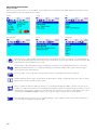
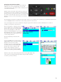
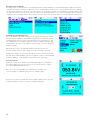
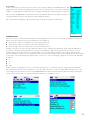
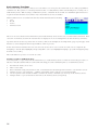
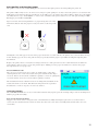
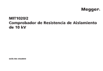
M
OTS80PB & OTS60PB
Oil Test Set
USER GUIDE
1
G
n
SAFETY WARNINGS
Safety warnings and precautions must be read and understood before the OTS80PB/OTS60PB is used. They must be observed during use.
n The OTS80PB/OTS60PB must only be used in the way intended and for the stated purposes described by Megger.
n The OTS80PB/OTS60PB must not be used if any part of it is damaged.
n The OTS80PB/OTS60PB must be properly earthed. A supplementary earth terminal is provided.
n Position the OTS80PB/OTS60PB so that power can be easily removed.
n The OTS80PB/OTS60PB must not be used in wet locations or with rain falling on the instrument.
n The OTS80PB/OTS60PB must only be used for testing electrical grades of insulating liquids. No other objects or substances should be placed in the test chamber.
n The OTS80PB/OTS60PB must only be used with one of Megger’s precision test vessels or VCM100D correctly fitted on the support horns in the test chamber.
n Replacement fuses must be of the correct type and rating.
n If batteries are fitted, the 12 VDC charger must only be powered from a negative earthed vehicle 12 VDC source using the Megger supplied lead.
n Calibration or repair must only be carried out by a Megger qualified repair facility.
n The test chamber must be kept clean and free from lint or other fibres.
n The OTS80PB/OTS60PB weighs between 16 kg and 23 kg. Care should be taken when lifting the instrument.
n It is prohibited to insert foreign objects into any gap on the instrument before or during a test.
n Unit must be used in a well ventilated location. Small quantities of Ozone may be created after prolonged testing.
NOTE
THE OTS80PB/60PB MUST ONLY BE USED BY SUITABLY TRAINED AND COMPETENT PERSONS.
IF THESE INSTRUMENTS ARE NOT USED IN THE MANNER SPECIFIED PROTECTION
MAY BE IMPAIRED
2
Symbols used on this instrument
G
Caution: refer to accompanying notes
F
Danger high voltage, risk of electrical shock
DC voltage
a
AC voltage
c
Equipment complies with current EU Directives
u
f
Earth terminal
Fuse
USB terminal
Equipment complies with ‘C tick’ requirements
Do not dispose of in the waste stream
3
Contents
Safety warnings
2
Symbols used on this instrument
3
General description
5
Features and benefits
6
Applications6
Instrument controls and indicators
7
Keypad and printer panel
7
Rear panel
8
Preparations for use
9
Getting started
9
Supply voltage
9
Assembly
9
Instrument setup procedure
9
Calibration
9
Test vessel mortised stirrer
9
Transportation and storage
9
Operating instructions
10
Top level tabs
10
Navigation and character entry
11
Set favourite test standards
12
Performing a breakdown test
12
Test in progress
12
Test results
12
Custom tests
13
Basic memory functions
14
Transfer results to USB flash drive
14
Print quality and changing paper
15
Vessel and electrodes
15
VCM100D/VCM80D
15
Test vessel motorised stirrer
15
Preventive maintenance
16
General
16
Cleaning
16
Care for OTS electrodes
16
New electrodes
16
Electrode storage
16
Cleaning oxidising/dirty electrodes
16
Technical specifications
17
OTS80PB/60PB technical specification
17
VCM100D/VCM80D voltage meters technical specification
18
Storage and transportation
18
Accessories and equipment
19
Optional
19
Spares
19
Repair and warranty
20
4
General description
Megger’s OTS80PB/60PB Oil Test Sets are portable
liquid dielectric breakdown testers. They are fully automatic, powered by battery/mains and facilitate accurate
breakdown voltage tests on mineral, ester and silicon
insulating oils. Used on site as well as in the laboratory,
the precision test vessel sets the accuracy standard for
the liquid insulation test industry. For ease of use the
instruments comes pre-programmed with a ‘library’ of
international breakdown test standards and the ability to
create custom tests.
The OTS60PB weighs less than 17 kg and the OTS80PB
21.5 kg to 23.5 kg depending on battery choice. It comes
complete with optional carry bag and optional impact
resistant transport case. The transport case provides
space for the unit, vessel and electrode set.
The instrument is housed in a metal case with moulded
end caps that accommodate convenient carry handles. The test chamber is designed with an easy-clean surface and
provides a drain for spilt oil through an internal pipe routed to the rear of the instrument. A beaker or similar can be
used for spillage collection. The test area is covered by a plastic lid with an electrically protective inner conductive layer
which, with the metal case, provides a safe equipotential enclosure for high voltage testing.
The lid allows in plenty of ambient light and users are able to view the test and witness stirring and the breakdown. The
chamber lid is dual redundant safety protected with micro-switches to prevent accidental electrification.
The advanced test vessel design yields highly accurate and repeatable results previously only produced by laboratory
instruments. Two stirring options are available; an internal magnetic bean stirrer which is dropped into the oil and an
optional lid mounted impeller that conforms to the ASTM D 1816 standard. Stirring during breakdown testing is
employed to produce an homogeneous distribution of contaminants within the oil and to free any carbon generated
between electrodes during testing.
Electrode gap is set by precision adjustment wheels that lock in position ensuring that the electrodes do not move
during a busy day in the field. It is, however, advisable to check the electrode condition and gap daily because it is a
critical parameter in breakdown voltage testing. Flat anodised Aluminium gap setting gauges are supplied in popular
sizes to facilitate electrode gap setting. Electrodes are detachable and are available in shapes that meet all international
standards, i.e. disk, spherical and mushroom (VDE) electrodes.
The OTS80PB is line powered with the option of internal batteries (either Lead Acid, NiMH or no battery) but the
OTS60PB only offers NiMH battery or no battery option. In addition to line power charging, a 12 V DC charger
facility is factory fitted with either battery option. A vehicle 12 V DC charger cable is provided to charge the instrument’s
batteries. Customers who order one of the battery pack options should be mindful of the need to maintain battery
capacity. As a minimum, lead acid batteries should be fully charged every 3 months. Customers who chose the NiMH
battery option are advised to operate from battery without line power periodically to ensure maximum battery life.
A selection of international breakdown tests are chosen from a library of standard sequences and started from the user
friendly menu on the LCD display. The top level test screen displays all pertinent test information to ensure the correct
electrodes are used with the specified electrode gap setting.
Results are viewed on screen and printed on either an external USB printer or the internal printer following a test result.
In the event of a breakdown not occurring before reaching the maximum voltage, the instrument will return maximum
voltage. This is a safety measure to ensure the instrument is not driven over its designed maximum voltage.
The instrument automatically turns off the display 15 minutes after completion of a test sequence or last use.
Safety features incorporated in the design include dual safety micro-switches and zero volt touch bar, the screened
chamber lid and convienent power supply On/Off switch. Pressing any button during a test will immediately remove the
high voltage and terminate the test. It is important to earth this instrument using the ground connection at the rear of
the instrument to ensure safe operation.
5
Features and benefits
n
n
n
n
n
n
n
n
n
n
n
n
n
Fully automatic breakdown tester with test voltages up to 80 kV / 60 kV depending on model
Advanced 400 ml oil vessel with accurate electrode gap setting and adjustment locking mechanism
Flat electrode gap gauges that will not damage electrodes
Easy clean test chamber with oil drain
Magnetic bead stirrer or optional lid mounted impeller (conforming to ASTM D 1816)
Direct trip control employing voltage and current measurement
Rapid response to trip (<10 μs)
Automatic oil temperature measurement
Intuitive user interface with backlit QVGA colour display (visible outdoors)
Simple transfer of test results via USB flash drive
Optional VCM100D/VCM80D voltage check units measure voltage directly
Optional carry case with shoulder strap
Optional transport case
Applications
The OTS80PB/60PB is used for determining the dielectric strength of high voltage insulating liquids, such as the
insulating oils used in transformers, switchgear and other electrical apparatus. The dielectric breakdown voltage is a
measure of the insulating ability of a liquid to withstand electrical stress. Contaminants such as cellulosic fibres,
conducting particles, dirt, and water reduce breakdown voltage of an insulating liquid. A low result indicates the
presence of one or more of these contaminants.
The test set is fully automatic. The operator has simply to prepare the test vessel, load it with sample oil, place it in
the test chamber, select the appropriate specification for the tests and then start the test sequence. The test set
automatically carries out the sequence of tests as defined by the pre-selected national specifications. Oil testing
specifications, for which the sets are pre-programmed, are as follows:
n
ASTM D 1816-04
n
ASTM D 877 A & B
n
BS EN 60156
n
CEI EN 60156
n
IEC 60156 1995-05
n
IRAM 2341-72
n
JIS C2101-99 (M) & (S)
n
PA SEV EN 60156
n
UNE EN 60156
n
NF EN 60156
n
SABS EN 60156
n
VDE 0370 Part 5
nAS1767.2.1
A critical factor with respect to field testing of oil is its temperature, because samples from a transformer taken shortly
after switch off can be many degrees hotter than equivalent room temperature laboratory tests performed at 20 ºC to
23 ºC. The OTS80PB/60PB instruments measure the oil temperature during the test so that temperature correction can
be applied to results.
NB: Certain standards require field tests to be performed between 20 ºC and 30 ºC.
6
Instrument controls and indicators
Keypad and internal printer panel
The control panel, illustrated below, is located to the front right side of the instrument and contains a QVGA colour
screen (1), navigation keypad with ‘OK’ (4) button and a ‘TEST’ (5) button. The operation is user friendly and driven
from six top level windows. A start-up LED (2) is used during instrument initialisation. The lower, vertical section of the
front panel houses an ON/OFF power switch (6) and a USB Type A interface socket
ItemDescription
1
3.5 inch, backlight, bright colour QVGA display
2
On/off LED
3
External power LED / icon
4
TEST’ button with associated red warning LED
5
USB socket
6
Navigation keypad with ‘OK’ select button
The instrument printer panel, shown below, houses the optional internal printer. A flat panel replaces the printer if not
ordered. The printer is a dot matrix impact printer with 57.5 mm wide paper roll. Paper results printed on this printer
will not blacken in high temperatures. The panel has two locking studs and a control print advance button.
7
Rear panel
The rear panel illustrated below accommodates all connections to the instrument with the exception of a front
facing USB interface.
Item Description
1Ground connection with cable lug
2IEC line power socket
3Fuses
4USB Type A socket
5USB Type B socket
612 VDC charger socket
It is mandatory for safe operation that an earth ground cable is attached to this instrument before performing tests. The
ground connection is identified as item 1 in the illustration. Attention must be paid to product warnings and markings.
Line power is applied via an IEC socket (2) and is fused (3). The internal batteries, if supplied, can be charged by a jack
type socket (6) from a vehicle or correctly rated wall plug transformer. If batteries are ordered with this product a
charger and vehicle charging cable is supplied. Note that the instrument is not designed to operate from 12 VDC, only
to charge the batteries.
Two USB interface connectors, one type A (4) and one type B (5), offer USB host and device interfaces. A second USB
type A (host) interface is located on the front of the instrument for user convenience. The USB type A interface (4) is
used to drive a printer or flash/hard disk drive.
8
Preparations for use
Getting started
It is important to read the user guide thoroughly before operating the OTS80PB/60PB for the first time. The safety
warnings are particularly important.
Supply voltage
Before connecting line power to the instrument the ground connector should be connected to a suitable earth point.
The OTS80PB/60PB is designed to operate on 50/60 Hz AC line power in the range 90 to 265 V AC. A 12 V DC power
circuit for battery charging is fitted when either NiMH or lead acid battery packs are ordered. The battery can be either
charged using the supply 12 V vehicle charger cable or from mains power.
Assembly
n
Unpack instrument and contents of the packing box.
n
Ensure that the instrument is placed on a solid surface or table with sufficient working space.
n
Connect ground to a suitable earth connector.
n
Fit selected electrodes to the threaded shafts in the test vessel taking care not to scratch electrode surfaces. Electrodes should be hand tightened onto the shafts to prevent any movement during use.
n
Adjustment of the electrode gap should be done with the feeler gauges provided, adjustment wheels locked and the gap rechecked.
n
Fit test vessel into instrument chamber.
n
If batteries are fitted, before switching on the instrument for the first time, connect power and leave for a period of at least four hours. This will ensure a full charge of the battery.
n
Read the section in this document entitled, “Instrument Operation” before powering up the OTS80PB/60PB for the first time.
n
Connect line power.
n
Turn on the instrument.
n
Follow the instrument setup procedure detailed below.
Instrument setup procedure
The required language option is selected from the top level tabbed window. Use the right arrow key to navigate across
the tabs to the language screen.The flag symbol is used as an icon representing language option. Simply use the up/
down arrow buttons to select the required language and press ‘OK’.
The following actions, accessed from the Settings tab window, should be taken before running a test:
1. Set date and time – Time/Date option.
2. Adjust the display backlight for optimum legibility – Display Setup option.
3. Select units - metric or imperial.
4. Set printer options.
Calibration
The OTS80PB/60PB are calibrated in the factory prior to delivery so there is no need to calibrate on initial setup.
The VCM100D/VCM80D voltage check devices can be used to confirm the output voltage of the instrument by reading
the voltage directly at the electrode before running tests. Periodic checking of actual test voltage using the VCM100D/
VCM80D is recommended. The voltage check test is accessed from the Tools tab window.
Test vessel motorised stirrer
Unpack the optional motorised stirrer assembly from its box and fit the stirrer shaft to the underside of the stirrer
assembly. The unit is ready for use. The oil test vessel lid is removed and the stirrer assembly used as a lid for tests that
require stirring.
When not in use care should be taken to store the stirrer shaft and stirrer lid assembly in the carry bag provided with the
instrument.
Transportation and storage
The OTS80PB/60PB are precision instruments that generates HV to 80 kV and needs to be transported and stored
carefully. A transportation case is available as an option and required by customers wanting to transport the OTS80PB
/60PB by road, rail or air.
The unit should be stored in a room or area where the environment is within the temperature range of -30 ºC to 65 ºC
and maximum humidity of 95% at 45 ºC.
9
Operating instructions
Top level tabs
The user is presented with a set of six tabbed, top level windows as depicted below which facilitate instrument control.
Left and right arrow keys navigate between tabs.
Home
Information SetupFile
Tools Language
The home tab contains summary information for each showing the selected automatic test standard, ID of
the asset the insulating liquid comes from, the type of insulator, electrode gap and the stirrer if required. This
is the main screen from which tests are run.
Setup window offers instrument settings of language (can also be set from language window – overcomes
difficulty when instrument is set to unknown languages), time/date, display, units, printer and a setting to
select fast detection of breakdown.
Users can print, save, recall, delete and download results to a USB drive from the file window.
The Information window offers details about the instrument software configuration/version as well as a help
function that serves as an indexed user guide.
The tools window offers the ability to manage test standards including the ability to define custom tests, favourite tests and add and remove new standards and standard upgrades via USB disk. An automatic electrode
clean function is included as a means of removing deposits from electrode surfaces. This window also runs a
test using the VCM100D/VCM80D voltage testers to check output voltage at the electrode barrier.
The flag symbol is used as an icon representing language option. Simply use the up/down arrow buttons to
select the required language and press ‘OK’.
10
Navigation and Character Entry
The keypad consists of arrow keys surrounding an
‘OK’ button used for navigating the screens and
selecting functions and options. These six buttons fully
control the instrument.
Within each user interface window the up and down
arrow buttons are used to navigate up and down the
functions listed on the left side of the screen. The ‘OK’
key either scrolls through options associated with each
function or enters a lower level window to perform a
function.
Left and right arrow buttons navigate between tabs on the top level window for optimum speed. Individual tab windows
save the highlight function and return to the same position on each screen.
Users can navigate into lower level windows using the up/down arrow buttons and the ‘OK’ button to reach, for
example, the ‘Display Setup’ function.
The user navigates to ‘Display Setup’ and
presses ‘OK’ to get to the display setup
window. The up/down or the left/right
buttons adjust brightness with a bar
indicator showing brightness percentage.
The ‘OK’ button is used to set brightness
after adjustment and subsequent return
to the settings window.
The following images illustrate this
function
A virtual QUERTY keypad that facilitates
alphanumeric entry to specify asset ID,
filename and custom test name.
A character is selected by navigating to
it, current character shows with a blue
background, and pressing the ‘OK’
button. After typing the required
characters the virtual keyboard ‘OK’ is
selected to return to previous window.
Numeric entry is via a virtual keypad as shown to the right. Digit entry
is the same as the full virtual keypad with a keypad ‘OK’ activating
a return to previous window.
11
Favourite test standards
It is important to setup favourite test standards from the standards library to avoid navigating thorough the entire list
each time you want to change to a different test. To do this navigate to the ‘Tools’ top level window and select ‘Manage
test standards’. Then move down to ‘Select favourite tests’ and choose only those tests which you require, making sure
you have the most recent version of each test, unless you specifically want to use an old test standard. Tests are greyed
out when selected. Simply return to the previous screens to save your selection. The screens below illustrate this process.
Performing a breakdown test
Select the ‘Home’ tab window using the arrow keys and ‘OK’ button. This
window offers a summary of information required for a measurement. The
following image shows a typical setup with the selected standard test, the
test identification or asset ID comprised of an asset number and two digit
serial number, the type of oil, required electrode gap, electrode shape and
finally the stirrer.
When the user selects a particular standard only valid options are
presented with respect to gap setting, electrodes and stirrer options.
Navigation is simple; up and down arrow buttons move up and down the
left side of the window whilst options for each line can be scrolled through
using the ‘OK’ key, or information entered in the case of Test ID.
Test in progress
During a test the screen flashes red warning HV symbols to remind the
user that a high voltage test is in progress. As a safety measure, any key
press will immediately halt the test.
The electrode potential difference is displayed as it ramps up in
over-sized digits to emphasise the presence of high voltage.
Between tests there is a dwell time and possibly a stirring action. A count
down timer indicates period of dwell or stirring remaining.
12
Test results
At the end of any test results are shown on the screen. A typical example is the IEC 60156 test. This
image shows the complete information presented to the user however the screen size is naturally
smaller so a slider function enables the user to navigate through the result and print it if required.
The test result for IEC60156 contains results of six sequential breakdown tests with test statistics of
average breakdown voltage, data dispersion and standard deviation.
The results window facilitates a direct print function at the bottom of the result window.
Custom tests
Custom tests are tests that can be defined by a user by giving the user control over the range of parameters set in a test.
Three custom tests have been pre-programmed for user definition;
n
Custom (5) – this test contains five successive breakdown tests
n
Custom (6) – this test contains six successive breakdown tests
n
Custom (10) – this test contains ten successive breakdown tests
Navigate to the Tools top level screen as illustrated below. Select, “Manage Test Standards” by pressing the OK button.
Go down to, “Edit Custom Test Parameters” and press the OK button. The custom parameters screen shows a set of
variables that control a breakdown test. Each variable is user settable, simply navigate down to the required setting,
press the OK button and proceed to change the value as required. For numeric entry on the OTS AF models the decimal
point can be entered by quickly pressing the digit ‘1’ twice. So to enter 2.5 mm gap setting the user enters the following
sequence:
n2
n
1, 1
n5
nOK
In the customs test parameters screen ‘set max. kV’ may appear as, ‘set kV (max. xxx)’ in certain versions of firmware.
All entry fields in the custom test parameters screen are range checked to ensure it is valid. When all values are set the
user navigates back to the Tools screen via the RETURN function. The user should ensure that Custom (5) and Custom
(6) are selected as favourite tests before leaving the manage test standards screen.
13
Basic memory functions
The internal memory is limited to fifty test records where a record represents a full result of one of the programmed
standard tests. Best practice is to backup internal results on a daily basis by either downloading data or saving onto a
USB memory device. When saving to USB memory device, a filename in the format of a maximum eight characters is
required and the filename entered must only contain characters A-Z, a-z and 0-9.
Memory functions are accessible from the files menu and include the following:
•Save
•Recall
•Delete
• Print last result
The user can select between internal memory and a USB memory device for the save, recall and delete functions. After
selection of a memory location the relevant files are displayed on screen. Navigation is via the arrow keys as follows:
Up and down arrow move up and down one item at a time. Left and right arrows implement a page up and page down
function to assist navigation where large numbers of file are present.
In the delete function window the user can select all, deselect all or select one file at a time. Select a single file by
navigating to the file (blue highlight) and pressing OK to select (red highlight changing to grey when navigating away
from the selected file.)
The recall function operates on one file at a time.
Transfer results to USB flash drive
Users may want to copy results from internal memory to a USB memory device as either an end-of-day procedure or
whenever the 50 result file limit is reached. The following procedure will backup files to a USB memory device:
1.
2.
3.
4.
5.
6.
14
From the file menu, select ‘Save’
Then ‘Select USB’
Enter a filename using only characters A-Z, a-z and 0-9 via the virtual keypad and return to save function screen
Navigate down to ‘Select Results’ – a full list of internally saved results are presented by TestID.
Select required results and then ‘SAVE’ to transfer the results to filename (as entered) on the memory device.
Navigate back to top level functions and remove the memory device (if required)
Print quality and changing paper
The printer cover is removed by turning the two fasteners through a quarter turn and pulling the panel off.
The printer ribbon may need to be moved on to improve print quality. To do this, remove the printer cover and turn the
right hand rotary winder in direction indicated on the ribbon case. To change the printer ribbon, simply press the ribbon
assembly where it says, “PUSH EJECT,” to remove the old ribbon and replace with a new one. The part is an Epson ERC09, Megger part number 25995-002.
Paper is fed into the housing with the lose paper facing the rear of the
instrument. Ensure that the paper is neatly cut and not curled up at the
end.
Holding the end of the paper roll, insert the paper under the cross bar and into the printer slot as shown (blue arrows)
in the drawing opposite. Press the print feed key repeatedly until the paper is just visible feeding through the print
mechanism.
Replace the printer front cover by first locating it at the base of the panel and secure it with the fasteners which are
turned back a quarter turn to secure the panel in place. Finally press the paper feed button to advance the paper
through the front cover paper slot.
Vessel and Electrodes
The oil test vessel and electrodes require no maintenance other than
cleaning. Electrodes can be unscrewed and replaced with another shape
electrode. Electrodes should be examined regularly to ensure no pitting has
occurred and the electrodes renewed where pitting is evident.
The instrument includes a built in electrode cleaning function which can be
activated from the tools menu. This function will perform 24 sequential
breakdowns to remove deposits on electrode surfaces.
VCM100D/VCM80D
The VCM100D/VCM80D are not user serviceable items but may require periodic cleaning using a clean cloth dampened
with Isopropyl Alcohol (IPA).
Test vessel motorised stirrer
Megger’s motorised stirrer is integrated into a modified lid assembly and simply replaces the vessel lid. Power is
connected via a flush mounted rear insert and is disconnected as the stirrer assembly is lifted. This unit is not user
serviceable.
15
Preventive maintenance
General
The OTS80PB/60PB is a HV instrument generating up to 80 kV and is not user serviceable. The user should ensure that
the lid is not cracked or distorted before use. The only internal part of the instrument that is accessible to the user is
the printer paper housing allowing renewal of paper and ribbon when required. Opening the OTS80PB/60PB is strictly
forbidden and will constitute a breach of warrantee. There is no need for any tools to be used with this instrument other
than the supplied gauges and magnetic bean retriever.
Cleaning
To clean the outer surfaces of the OTS80PB/60PB, first disconnect from line power and then wipe the instrument using a
clean cloth dampened with Isopropyl Alcohol (IPA).
The user must ensure that the test chamber is always kept clean, particularly prior to a test. Wipe away any spilt oil in
the chamber or on the outside of the test vessel with a lint free cloth. When a lot of oil is spilt in the test chamber the
unit is designed with a drain facility at the rear. Simply unclip the clear tube and drain oil into a beaker or other suitable
container.
To clean the inside of the test vessel follow the instructions given in the relevant test specification or, in the case of no
instructions, cleaned with a small volume of the next sample of oil to be measured.
Care for OTS electrodes
Brass electrodes supplied with the Megger oil test sets will show signs of deposits built up from insulating oil breakdown
testing. If left they will oxidise and appear dull.
New electrodes
Megger electrodes are supplied in a kit with gap gauges and magnetic stirrer beans and retrieval stick. the electrodes
have different shapes but are cared for in the same way. If new electrodes require cleaning, isopropyl alcohol (IPA) may
be used to clean them off. It is advisable to immerse the electrodes in clean insulating oil for a couple of hours prior to
use.
Electrode storage
Electrodes may be stored in a suitable container or immersed in clean mineral insulating oil. Electrodes in a test vessel
left to stand overnight may be left with the last oil sample tested in the vessel.
Cleaning oxidised/dirty electrodes
Dirty electrodes may be cleaned with a clean, soft cloth and brass cleaner but care should be taken to use minimal
pressure to avoid removal of excessive electrode material. After removing the dirt clean the electrodes with a clean cloth
and IPA. It is advisable to immerse the electrodes in clean insulating oil for a couple of hours prior to use.
If electrodes are pitted or scratched they should be discarded and new electrodes fitted.
16
OTS80PB/OTS60PB
Technical Specification
The following technical specifications apply to the OTS80PB/60PB:
Test voltage
-40 to 0 to 40 kV, -30 to 0 to 30 kV @ 61.8 Hz
Voltage resolution
0.1 kV
Voltage accuracy
±1% ±2 digits
Vessels
400 ml (standard)
150 ml (option)
Thermoplastic polyamide chamber provides precision electrode alignment, adjustment wheels lock electrodes in position
Temperature sensor resolution
1 ºC
Power supply
Line voltage/power 90 to 264 VAC, 300 VA
Line frequency 48 / 63 Hz
Fuses
2 x 4 A CFST ceramic, 20 mm x 5 mm, for 250 V
Batteries (optional)
Lead Acid 2 x 12 V 4 Ah, or NiMH 24 V 2 Ah
DC power supply 12 VDC, 60 VA – fitted with battery option, used to charge battery only
Internal printer (option)
Dot matrix impact printer with graphical output
Paper 57.5 mm wide, weight 52 gm per roll
Epson black ribbon cassette ERC-09B
Protection
Safety interlock on test chamber
Discharge barrier on polycarbonate test chamber cover
Display
320 x 240 QVGA colour display with backlight
Dimensions (W x H x D)
OTS80PB
520 mm x 380 mm x 250 mm
520 mm x 330 mm x 250 mm
OTS60PB
Weight
OTS80PB
20.5 kg (no battery)
21 kg (NiMH battery)
23.5 kg (with Lead acid batteries)
OTS60PB
16.3 kg (no battery)
16.8 kg (NiMH battery)
Operating temperature
0 ºC to +50 ºC
Storage temperature
-30 ºC to +65 ºC
Humidity
80% RH at 40 ºC operation
95% RH at 40 ºC storage
Altitude
1000 m
Safety
Designed in accordance with IEC61010
EMC
Light industrial IEC 61326-1 Class B, CISPR 22, CISPR 16-1 and CISPR 16-2
17
VCM100D/VCM80D Voltage check meters
Technical Specification
The VCM100D and VCM80D are OTS accessories that enable the voltage output of the oil test set to be checked by
measuring the actual voltage at the HV electrodes. The calibration meters fit in the oil test set chamber in place of a
standard vessel and are designed to ensure that the load on the OTS transformer is similar to the load during an oil
dielectric strength test.
Meter type
Proprietary 100 kV/80 kV Megger OTS voltmeter with 4 seven-segment digit digital readout
Accuracy at 23 °C
2.0% plus 2 digits to 50 kVrms
2.5% plus 2 digits > 50 kVrms to 75 kVrms
3.0% plus 2 digits > 75 kVrms to 100 kVrms (VCM100D only above 80 kV)
Temperature range
Operational
0 °C to 40 °C
Storage
-30 °C to +70 °C
Humidity range
Operational
50% RH at 20 °C
Storage
93% RH at 40 °C
Safety
The meter is only approved for use with Megger oil test sets
Dimensions (W x H x D)
250 mm x 150 mm x 115 mm
Weight
1.8 kg
Storage and transportation
The OTS80PB/60PB are precision instrument that generates HV to 80 kV and needs to be transported and stored
carefully. A transportation case is available as an option and required by customers wanting to transport the
OTS80PB/60PB by road, rail or air. A soft, shoulder carry case is provided as an option with the OTS80PB/60PB. It opens
up to facilitate running a test without removal of the instrument and provides two side pouches for storage.
The unit should be stored in a room or area where the environment is within the temperature range of -30 ºC to 65 ºC
and maximum humidity of 95% at 45 ºC.
If the OTS80PB/60PB has batteries fitted it should be fully charged at least once every three months to maintain full
battery capacity.
18
Only Megger supplied accessories can be used with the OTS range. Non approved
equipment cannot be guaranteed to work with the OTS.
Factory fitted accessories
n
n
n
n
n
n
Internal printer
Battery – either Lead acid (OTS80PB only), NiMH battery or no battery (line power only) option
Internal 12 V charger and 12 V vehicle cable to charge batteries (not to operate the instrument)
Electrode sets – IEC, ASTM and full electrode set containing one of each type of electrode
Vessel lid mounted impeller for use with 400 ml vessel
Power lead
Optional accessories & spares
n
n
n
n
n
n
n
n
n
Transportation case
VCM100D/VCM80D voltage check meters
Vessel assembly 400 ml
Vessel assembly 150 ml
Vessel lid mounted impeller for use with 400 ml vessel
Electrode sets IEC 156
Electrode set ASTM D 877/1816
Full electrode set – contains all electrodes
Printer paper
19
Repair and warranty
The Test set circuit contains static sensitive devices, and care must be taken in handling the printed circuit board. If the
protection of a product has been impaired it should not be used, and be sent for repair by suitably trained and qualified
personnel. The protection is likely to be impaired if, for example, the product shows visible damage, fails to perform the
intended measurements, has been subjected to prolonged storage under unfavourable conditions, or has been exposed
to severe transport stresses.
New products are guaranteed for 1 year from the date of purchase by the user.
Note: Any unauthorized prior repair or adjustment will automatically invalidate the warranty.
Note: Please ensure when returning an instrument for repair or warranty it is adequately packed. It is
recommended that the original packaging is taken note of, or retained, in case it is required. The instrument
should be carefully boxed and protected, and then be securely strapped to a pallet. Please note that damage
caused in transportation due to poor packaging may invalidate a warranty claim.”
Instrument repair and spare parts
For service requirements contact:–
Megger Limited or
Megger
Archcliffe Road Valley Forge Corporate Center
Dover 2621 Van Buren Avenue
Kent, CT17 9EN
Norristown, PA 194
EnglandU.S.A.
Tel: +44 (0) 1304 502243
Tel: +1 (610) 676-8579
Fax: +44 (0) 1304 207342 Fax: +1 (610) 676-8625
or an approved repair company.
Approved repair companies
A number of independent companies have been approved for repair work on most Megger products, using genuine
Megger spare parts. Consult the Appointed Distributor / Agent regarding spare parts, repair facilities and advice on the
best course of action to take.
Returning a test set for repair
If returning a test set to the manufacturer for repair, it should be sent freight pre-paid to the appropriate address. A copy
of the invoice and of the packing note should be sent simultaneously by airmail to expedite clearance through customs.
A repair estimate showing freight return and other charges will be submitted to the sender, if required, before work on
the instrument commences.
End of life disposal
WEEE
The crossed out wheeled bin placed on the Megger products is a reminder not to dispose of the product at the end of
it’s product life with general waste.
Megger is registered in the UK as a Producer of Electrical and Electronic Equipment.
The Registration No is WEE/HE0146QT
Batteries
The crossed out wheeled bin placed on the batteries is a reminder not to dispose of them with general waste at the end
of their life.
OTS60PB
This instrument is supplied with either no battery fitted or with a NiMH battery pack fitted.
OTS80PB
This instrument is supplied with either, no battery fitted, a sealed lead acid battery, or a NiMH battery pack fitted.
All OTS60PB and OTS80PB instruments are fitted with a lithium Ion memory backup cell, 3V 220mAh CR2032 type.
20
The CR2032 battery replacement should only be performed by a Megger authorised repair agent, who will correctly
dispose of the spent battery.
For end of life disposal only the CR2032 backup cell is located in the front panel module mounted behind instrument’s
display. These are classified as Portable Batteries and should be disposed of in the UK in accordance with Local Authority
requirements
The sealed lead acid battery replacement should only be performed by a Megger authorised repair agent, who will
correctly dispose of the spent battery.
For end of life disposal only, the sealed lead acid batteries are located behind the right hand end panel. These are
classified as Portable Batteries and should be disposed of in the UK in accordance with Local Authority requirements.
The NiMH battery pack replacement should only be performed by a Megger authorised repair agent, who will correctly
dispose of the spent battery.
For end of life disposal only, the sealed lead acid batteries are located behind the right hand end panel. Spent NiMH
batteries are classified as Industrial Batteries. For disposal in the UK contact Megger Ltd.
For disposal of batteries in other parts of the EU contact your local distributor. Megger is registered in the UK as a
producer of batteries. The registration number is BPRN00142
21
M
AUSTRALIA
Megger Pty Limited
Unit 1, 11-21 Underwood Road
NSW 2140
T +61 (0)2 9397 5900
F +61 (0)2 9397 5911
E [email protected]
DUBAI
Megger
Dubai
United Arab Emirates
T +971 4 456 9057
E [email protected]
CANADA
Megger
110 Milner Avenue Unit 1
Scarborough Ontario M1S 3R2
T +1 416 298 9688 (Canada only)
T +1 416 298 6770
F +1 416 298 0848
E [email protected]
FRANCE
Megger SARL
Z.A. Du Buisson de la Couldre
23 rue Eugène Henaff
78190 TRAPPES
T +33 (0)1 30.16.08.90
F +33 (0)1 34.61.23.77
E [email protected]
DEUTSCHLAND
Megger GmbH
Obere Zeil 2
61440 Oberursel
T 06171-92987-0
F 06171-92987-19
E [email protected]
INDIA
Megger (India) Pvt Limited
501 Crystal Paradise Mall
Off Veera Desai Road
Andheri(w)
Mumbai - 400053
T +91 22 26740468
F +91 22 26740465
SOUTH AFRICA
PO Box 22300
Glen Ashley 4022
Durban
South Africa
T +27 031 5646578
F +27 031 5637990
SCHWEIZ
Megger AG
Ob. Haselweg 630
5727 Oberkulm, Aargau
T +41 62 768 20 30
F +41 62 768 20 33
THAILAND
Megger
30/46 Moo 13
Nongprue, Banglamung
Chonburi 20150
T +66 860103395
E [email protected]
UNITED KINGDOM
Megger Limited
Archcliffe Road, Dover
Kent CT17 9EN
T +44 (0)1 304 502101
F +44 (0)1 304 207342
E [email protected]
USA
Megger
4271 Bronze Way, Dallas,
Texas 75237-1019
T +1 800 723 2861 (USA ONLY)
T +1 214 333 3201
F +1 214 331 7399
E [email protected]
USA
Megger
Valley Forge Corporate Centre
2621 Van Buren Avenue
Norristown, PA 19403
T +1 610 676 8500
F +1 610-676-8610 (USA ONLY)
E [email protected]
USA
Megger
4064 State Highway 6 South
College Station, TX 77845
T +1 979 690 7925
F +1 979 690 0276
E [email protected]
SVERIGE
Megger Sweden AB
Eldarvägen 4
Box 2970
SE-187 29 TÄBY
T +46 8 510 195 00
F +46 8 510 195 95
E [email protected]
This instrument is manufactured in the United Kingdom.
The company reserves the right to change the specification or design without prior notice.
Megger is a registered trademark
Part No. OTS80PB_OTS60PB_en_V09 0113
22