1
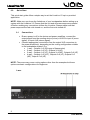
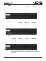
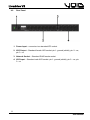
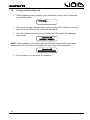
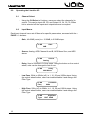
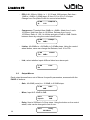
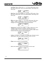
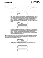
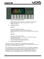
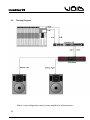
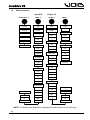
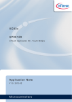
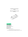
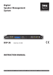
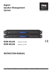
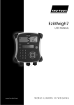
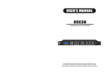
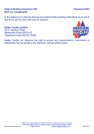
Livedrive V2 User Manual Livedrive V2 0.0 Quick Start This quick start guide offers a simple way to set the Livedrive V2 up in a practical application. NOTE: Make sure you know the limitations of your loudspeakers before setting up a system with the Livedrive V2. Ensure that the unit and all power amps are powered off before making any connections to/from the Livedrive. Always make sure that power amps are the last units turned on, and the first units turned off. 0.1 Connections Ensure power is off to the device and power amplifiers, connect the output signal from the sending device (mixer) via XLR to input A (mono signal), or input A+B (stereo signal). Connect appropriate connections from the output XLR connectors to the power amplifier(s), depending on the routing configuration suitable to the loudspeaker system. E.g. 1-way – Outputs 1+2 (full range of frequencies) 2-way – Outputs 1+2 (LF), Outputs 3+4 (HF) 3-way – Outputs 1+2 (LF), Outputs 3+4 (MF), Outputs 5+6 (HF) 4-way – Outputs 1+2 (VLF), Outputs 3+4 (LF), Outputs 5+6 (MF), Outputs 7+8 (HF) NOTE: There are many more routing options other than the examples but these options are basic configurations for beginners. 1-way 2 User Manual Livedrive V2 2-way 3-way 4-way Once all connections are made, you are ready to begin the set up of the system. 3 User Manual Livedrive V2 0.2 Step-by-step 1. Power up the sending device (mixing desk), then power up the Livedrive V2, make sure the power amplifiers are off before powering either of the other devices up. 2. On the Livedrive V2, press the Menu button until the routing page is displayed, then with the control wheel scroll through until the desired routing method is on the display. Press Exit to return to the main page. 3. Now, use the CH Select +/- buttons to scroll through to Out 1. Use Page – to get to the link page, ensure link is On (if channel display is Out 12 then the link is already on). Repeat this for outputs 3/4, 5/6 and 7/8. 4. For the crossovers on each linked output channel, scroll through channel pages until LowPass is displayed. Using the control wheel, and control wheel button, set the desired frequency, filter type and check the LPF is enabled. 5. For the HPF, scroll across one page to HighPass and repeat the process. 6. Now the crossovers are set, scroll through the remaining pages to set the values for the rest of the settings (EQ, Limiter, Delay) for each output channel. There are multiple parameters to some settings, use the control wheel button to change between them. 7. To store the program, press the Menu button until Save is displayed. Use the control wheel button to select and choose the name of the preset. Use Exit to backspace. Press Menu again for saving no/yes. 8. When the preset/program has been finalised and saved, power up the power amplifiers. Now the system is ready to go. NOTE: Alternatively, setting up a preset can be made beforehand on the live link software and synced with the Livedrive V2 unit. This allows the user to simply connect the unit to a computer with Live Link, plug in the appropriate connections, turn each part of equipment on in the correct order,then the system is ready to go. 4 User Manual Livedrive V2 Livedrive V2 User Manual 5 User Manual Livedrive V2 Contents 0.0 Quick Start....................................................................................................... 1 0.1 Connections .................................................................................................. 2 0.2 Step-by-step................................................................................................. 4 1.0 Introduction to Livedrive V2 .............................................................................. 8 2.0 Features ........................................................................................................... 9 3.0 Front Panel..................................................................................................... 10 4.0 Rear Panel ..................................................................................................... 11 5.0 Turning on the Livedrive V2............................................................................ 12 6.0 Operating the Livedrive V2 ............................................................................. 13 6.1 Channel Select............................................................................................ 13 6.2 Input Menus ................................................................................................ 13 6.3 Output Menus.............................................................................................. 14 6.4 System Menus ............................................................................................ 16 7.0 Live Link Control Interface.............................................................................. 18 7.1 Minimum System Requirements ................................................................. 19 7.2 Installing Live Link....................................................................................... 19 7.3 Connecting the Livedrive V2 ....................................................................... 19 7.4 Starting Live Link......................................................................................... 20 7.5 Using Live Link............................................................................................ 20 7.6 Livedrive V2 Control Window ...................................................................... 20 7.6.1 Main...................................................................................................... 20 7.6.2 X-Over .................................................................................................. 21 7.6.3 Input A-D .............................................................................................. 21 7.6.4 Output 1-8............................................................................................. 22 6 User Manual Livedrive V2 8.0 Specifications ................................................................................................. 24 9.0 Routing Diagram ............................................................................................ 25 10 Menu Structure............................................................................................... 29 11.0 Service ........................................................................................................ 30 11.1 Worldwide Service ................................................................................... 30 11.2 Warranty Registration .............................................................................. 30 11.3 Environmental .......................................................................................... 30 12.0 Warranty ..................................................................................................... 31 7 User Manual Livedrive V2 1.0 Introduction to Livedrive V2 The Void Acoustics Livedrive V2 is a full 4 analog input, 1 (2-channel) AES input, 8 output digital loudspeaker management system. Designed specifically for live sound, touring, fixed installations, stage and theatre productions, bar, club and conference applications. Through matrix mixing, any input can be routed to any output at any level, using high quality 24 bit A/D and D/A converters with the latest 64 bit processors, allowing unparalleled bandwidth from 5Hz to 45kHz. Inputs A, B, C and D are analogue, and AES is digital, which can handle clock speeds of up to 192kHz. Each input and output on the Livedrive V2 includes a 6/12/18/24dB HPF and LPF that can be set anywhere between 10Hz – 20kHz as Bessel, Butterworth or LinkwitzRiley filter types. There is also control of 10 parametric EQs per Input/Output channel with filter types bell, high shelf, low shelf, notch and allpass. When connected via USB or Ethernet to a Windows/Mac OSX PC, the Livedrive V2 can be controlled from the front panel or through the purposely designed Live Link software, which can be set up with an IP address on a network in order to run multiple devices. Shipping contents: - Livedrive V2 unit - User manual - USB Cable - Live Link software CD - Power cable NOTE: Be sure to check for any missing items or damage when opening the box. If this does occur, please immediately contact the Void distributor where the product was purchased from, or contact Void directly. 8 User Manual Livedrive V2 2.0 Features 118dB dynamic range (inputs) / 114dB dynamic range (outputs) 6 Inputs (4x Analogue, 1x(2-channel) Digital AES/EBU) & 8 Outputs with matrix mixing. Balanced inputs Matched-impedance outputs Frequency range of 10Hz - 30kHz Input gain up to +12dB 10 Parametric EQ's per input and output. Each can be set as Bell, High/Low shelf, Notch and Allpass. Compressor 2s delay per input and output Limiter 180° phase Nominal Input and output level +6dB. Maximum input level +22dB. Maximum output level +12dB. 640μs latency 64-bit DSP High quality 24-bit A/D & D/A converters USB/Ethernet interface for remote control/configuration on a PC Accurate control of delay, level, polarity and limiters Full range of crossover control parameters Ability to program & store up to 100 preset. Security lock CPU and DSP upgrades via PC 9 User Manual Livedrive V2 3.0 Front Panel 1. USB Port – standard Type-B female socket. 2. Peak Level LED – shows the current peak of the signal: SIG, -6dB, Limit, Clip. Input’s Limit = Max. Headroom. Output Limit = threshold of limiter. 3. Menu & Control Keys – CH SELECT + PAGE + MENU EXIT Previous channel Next channel Previous page Next page System information Return to main menu, backspace 4. LCD – Displays information about the unit 5. COPY - *WILL BE AVAILABLE IN A FIRMWARE UPDATE* 6. PASTE - *WILL BE AVAILABLE IN A FIRMWARE UPDATE* 7. Control Wheel – gives velocity sensitive control over parameter values. There is also a button click to allow changing parameters. 8. Mute – mutes/un-mutes the corresponding output channel. When a channel is muted, a red LED will light up. 10 User Manual Livedrive V2 4.0 Rear Panel 1. Power Input – connects via a standard IEC socket. 2. XLR Output – Standard female XLR socket: pin 1: ground (shield), pin 2: +ve, pin 3: -ve 3. Network Socket – Standard RJ45 female socket 4. XLR Input – Standard male XLR socket: pin 1: ground (shield), pin 2: +ve, pin 3: -ve 11 User Manual Livedrive V2 5.0 Turning on the Livedrive V2 When powering up the Livedrive V2 an initialization screen will be displayed on the LCD screen. Initializing . . . The device will take a few seconds to boot up during the initialization process, where all of the LEDs on the front panel will light up. Once the initialization process has finished, the LCD screen will displaythe main screen. Livedrive V2 DEFAULT PRESET NOTE: when powering up the device after the first time and/or presets have been made/saved, the main screen will display the name of the last used preset. Livedrive V2 XXXXXXXXXXXXXXXXXX The Livedrive V2 is now ready for operation. 12 User Manual Livedrive V2 6.0 Operating the Livedrive V2 6.1 Channel Select - 6.2 Using the CH Select +/- buttons, users can select the channel(s) to control. This can be Input AB, CD, and Output 12, 34, 56, 78. When link is selected off the inputs and outputs become uncoupled. Input Menus Each input channel has a set of Menus for specific parameters, accessed with the – PAGE + / - buttons. - Gain, -48.00dB (mute) to +12.00dB, in 0.25dB steps. In AB Gain 0dB - Source, Analog, AES Channel A and B, AES Mono Sum, and AES stereo In AB - Delay, 0ms to 2000ms in 0.01ms steps. Using the button on the control wheel, units can be changed to feet or mm. In AB - Delay 000.000ms Low Pass, 50Hz to 20kHz (off), in 1, 10, 50 and 100Hz steps. Using the control wheel button, users can enable/disable it and change the Filter Type. In AB Freq: - Source Analog LowPass 80Hz High Pass, 20Hz (off) to 20kHz, in 1, 10, 50 and 100Hz steps. Using the control wheel button, users can enable/disable it and change the Filter Type. In AB Type: HighPass BUT 24dB 13 User Manual Livedrive V2 - PEQ 1-10, 20Hz to 20kHz, in 1, 10, 50 and 100Hz steps. Gain from 12dB to +12dB in 0.25dB steps. Q from 0.10 to 25 in 0.10 steps. Change from Freq/Gain/Q with the control wheel button. In AB Q: 1.00 - PEQ XX Compressor, Threshold from 24dBu to -48dBu. Attack from 1ms to 10,000ms. Hold from 0ms to 10,000ms. Release from 1ms to 10,000ms. Ratio of 1.20:1 to Infinite and gain of 0dB to 12dB. Switch between these by using the control wheel button. In AB Compr. Thr: 0dBu - Limiter, -48.00dBu to +24.00dBu, in 0.25dBu steps. Using the control wheel button, users can change the Release, from 10 to 100. In AB Thr.: 0dBu - Link, select whether inputs A/B are linked as a stereo pair. In AB On 6.3 Limiter Link: Output Menus Each output channel has a set of Menus for specific parameters, accessed with the PAGE +/- buttons. - Gain, -48.00dB (mute) to +12.00dB, in 0.25dB steps. In AB Gain 0dB - Mixer, Input A-D -48dB to 0dB. Out 1 Input A - Delay, 0ms to 2000ms in 0.01ms steps. Using the button on the control wheel, units can be changed to feet or mm. Out 1 14 Mixer 0dB Delay 00.000ms User Manual Livedrive V2 - Low Pass, 50Hz to 20kHz (off), in 1, 10, 50 and 100Hz steps. Using the control wheel button, users can enable/disable it and change the Filter Type. In AB Freq: - High Pass, 20Hz (off) to 20kHz, in 1, 10, 50 and 100Hz steps. Using the control wheel button, users can enable/disable it and change the Filter Type. In AB Type: - LowPass 80Hz HighPass BUT 24dB PEQ 1-10, 20Hz to 20kHz, in 1, 10, 50 and 100Hz steps. Gain from 12dB to +12dB in 0.25dB steps. Q from 0.10 to 25 in 0.10 steps. Change from Freq/Gain/Q with the control wheel button. In AB Q: 1.00 - PEQ XX Compressor, Threshold from 24dBu to -48dBu. Attack from 1ms to 10,000ms. Hold from 0ms to 10,000ms. Release from 1ms to 10,000ms. Ratio of 1.20:1 to Infinite and gain of 0dB to 12dB. Switch between these by using the control wheel button. In AB Compr. Thr: 0dBu - Limiter, -48.00dBu to +24.00dBu, in 0.25dBu steps. Using the control wheel button, users can change the Release, from 10 to 100. In AB Thr.: 0dBu - Phase, can be normal or inverted polarity. Out 1 Normal - Limiter Phase: Link, select whether outputs 1/2 are linked as a stereo pair. Out 12 On Link: 15 User Manual Livedrive V2 6.4 System Menus The system menus show information about the device and allow the user to change some system parameters. These menus are accessed by pressing the MENU button repeatedly. Press Exit to return to the main page . - Load, Shows the program #1-100 and the first 16 characters of the program name. Load the preset by clicking the control wheel button. Load: 1 XXXXXXXXXXXXXXXX - Save, Stores the current settings to the designated program #1-100 by clicking control wheel. Users can set a custom name for the program with a combination of the control wheel and control wheel button. To delete a character, the EXIT button is pressed, to cancel storing a program, all characters must first be deleted, and then the EXIT button pressed. Save: 3 EMPTY Set Presetname: XXXXXXXXXXXXXXXX - Access Level, Unlocked or ****Locked****. This allows the user to secure the unit and prevent changes on the device. To lock/unlock the device a password is required by pressing the control wheel button. To delete a character whilst entering a password, the EXIT button is pressed. Press the menu button once the password has been entered to confirm it, and then again to set it. NOTE: Locking the unit will lock any parameters from being changed. To unlock the unit in order to make further changes, use the same process required to lock the device with the same password entered. Access Level : Unlocked - Version Info/IP Address/MAC Address, Information for the user about the device. Includes Serial Number, software version, hardware version, IP address and MAC address. Version Info SN: XXXXXXXXXXXXX IP Address XXX.XXX.XXX.XXX 16 User Manual Livedrive V2 - Routing, changes the configuration of the device: Mode Stereo 1-Way Stereo 2-Way Stereo 3-Way Stereo 4-Way Mono 8-Way Out 1 In1 In1 In1 In1 Any Out 2 In2 In1 In1 In1 Any Out 3 Out 4 Out 5 Out 6 Out 7 Out 8 In2 In1 In1 Any In2 In2 In1 Any In2 In2 Any In2 In2 Any In2 Any In2 Any 17 User Manual Livedrive V2 7.0 Live Link Control Interface The Livedrive V2 is enhanced by the Live Link software for Windows and Mac OSX which allows the user to have real-time, remote control via either USB or Ethernet. Utilizing this software makes using the Livedrive V2 easier for the user to manipulate and monitor the device, as it provides more accurate control over each parameter. Users have separate tabs for each Input and Output channel, as well as a tab specifically for the crossovers, which, with the Graphical User Interface (GUI) makes it easier to physically see the changes in LPF/HPF or EQ. The limitation of 100 preset programs on the Livedrive V2 does not necessarily apply when using the Live Link software, as more programs can be created and stored even when the device isn’t connected. The device must be connected in order to write/modify programs onboard. 18 User Manual Livedrive V2 7.1 Minimum System Requirements - 7.2 Windows XP (with service pack 2), 7 or Mac OSX 10.5.8 or higher. USB or Ethernet port for connecting the Livedrive to the PC. Pentium 4 or higher Installing Live Link Windows: - Insert the included CD into the PC. Follow the instructions on the Setup Wizard carefully. Once the installation has finished, close the Setup Wizard and remove the CD. Mac OSX: 7.3 Insert the included CD into the PC Double click on the disk on the desktop to open the files and open Void_DSPControl.mpkg Follow the instructions in the Setup Wizard. When the installation has finished, eject the CD. Connecting the Livedrive V2 The Livedrive V2 can be connected to a PC via USB or Ethernet network. Connection via USB requires the provided USB cable to be plugged into the front of the Livedrive V2, and any USB port on the PC. When connecting the Livedrive via Ethernet to the PC, an IP address is required for communication between the device and the PC. Connecting the Livedrive V2 to the computers network router will assign an IP address automatically through the networks DHCP. This configuration is useful for installations, where there will be more than one device controlling the system, as users are able to connect the 19 User Manual Livedrive V2 devices to a network and control each of them separately from one PC, connected to the network by Ethernet or wirelessly. NOTE: To configure a manual IP address when connected via Ethernet, on the main window of Live Link, go to the top menu bar Hardware -> Configure -> Network 7.4 Starting Live Link To open the Live Link software in Windows, find the icon either on the desktop and double click. The program can also be found in the start menu -> Void -> Void DSP Control, and through Windows Explorer. To open the Live Link software in Mac OSX, find Void_DSPControl.app in the applications folder in Finder, or in the applications folder in the dock. 7.5 Using Live Link Once the software has opened, the Void Network Control Software window is shown. If the Livedrive V2 is connected, ‘All Units (1 unit online)’ is shown, and beneath it the Livedrive V2 and information, e.g. the reference/address. To access the Livedrive V2’s main control window, press the ‘>>’ button. 7.6 Livedrive V2 Control Window Within the main control window, there are 14 tabs to control the 4 inputs, 8 outputs, crossovers and the main window. Note: Any changes made to any parameters on Live Link whilst the Livedrive V2 is connected will change the same parameter on the device. If the device is disconnected and the changes weren’t stored, the data will be lost from the device. 7.6.1 - Main A mixing window for all inputs/outputs, allowing the user to adjust the level of inputs/outputs relative to one another from -48.00dB (mute) to +12dB through the use of the faders. There are Mute buttons below each fader which cut the corresponding channel (red when active), as 20 User Manual Livedrive V2 well as Link buttons, which join two channels (A/B, C/D, 1/2, 3/4, 5/6, 7/8) together to form a stereo pair. Users have store/loading options both for the device and the PC on the software, under Local Presets users can store/load a program from/to their computer, and under Unit Presets users can store/loaded from the device. NOTE: To store a preset from the computer onto the device, it must first be loaded into Live Link and then the Store button pressed under Unit Presets. It would be advisable for the user to check on the device that the preset has loaded before disconnecting. 7.6.2 - - - This tab shows the crossovers for each of the 8 outputs. The right-hand side of the window includes metering for each output, -48dB to +12dB, as well as Link buttons for stereo linking outputs 1/2, 3/4, 5/6, 7/8. The Mute buttons below will cut the corresponding channel. The Phase Invert buttons determine the polarity of the output, either Normal (+) or Inverted (-). The HPF/LPF for each channel is at the bottom of the window. Users can enter the value for the frequency in the number box or click the corresponding triangles in the frequency graph to manipulate it. This applies for both HP and LP filters. The drop down menus for the HPF/LPF allows the user to choose the filter type: Bessel, Butterworth or Linkwitz-Riley from 6dB/Octave curve to 24dB/Octave. Below the HPF/LPF, there is a gain and delay control on each channel. The gain from -48.00(mute) to +12.00dB for level adjustment, and delay from 0 to 2000ms. 7.6.3 - - - X-Over Input A-D Each input tab contains EQ, Limiter, Gain and LPF/HPF controls. Every individual EQ in the 10-band EQ allows frequency control from 10Hz – 20kHz, gain +/-15dB and Q from 0.2 to 25.0 for each channel, which is visually represented in the graph above. Each EQ can be manipulated by left-clicking on the respective square in the EQ graph, and dragging with the mouse. The Q can be changed by right-clicking the respective square and dragging from left-right. Below the EQ matrix is the HPF/LPF controls. The number box sets the frequency (20Hz to 20kHz), and the drop down menu chooses the filter type (Butterworth, Bessel, Linkwitz-Riley, 6dB/Octave to 24dB/Octave). The gain fader on the right-hand side of the window, as well as the mute button coincides with the fader in the Main tab’s mixing matrix. The delay control offers a delay from 0ms to 2000ms, but the units can be changed to feet, inches, mil, meters, millimetres and seconds. 21 User Manual Livedrive V2 - - The Limiter is located to the right of the delay control. This ensures that clipping does not occur when the signal goes above the set threshold (between -48.00dBu and +12.00dBu). The release can be set between 1ms and 100dB/s. There is also a feature called "COMP" which will open up a compressor in a new tab. Within this, the threshold can be changed (-48dBu to 24dBu). Attack, hold and release ranges from 1-10,000ms. Ratio (1.2:1 - Inf:1) and Makeup Gain from -12dB to +12dB. 7.6.4 - - - - - Output 1-8 Each output tab contains control of 10 EQs, a Limiter, Delay, LPF/HPF, Polarity, Gain and an Input Mixer. The EQ is the same as the EQ for Inputs A-D, with a 10Hz – 20kHz frequency range, -15.00dB to +15.00dB range of gain and a Q from 0.20 to 25.00. Changing any of the EQ settings is represented in the graph above the EQ control matrix. Using the mouse's left/right clicks and dragging the EQ square in the EQ graph, users can physically manipulate each EQ band’s frequency and Q. Along the bottom of the window is the HPF/LPF, these can be set anywhere between 20Hz and 20kHz with the number box, and the drop down menu chooses the type of filter (Butterworth, Bessel, LinkwitzRiley from 6dB/Octave to 24dB/Octave). The gain fader on the right-hand side of each output tab relates to the fader in the Main tab’s mixing matrix. If the gain is changed in either of these windows, it will affect it in the other. The delay control ranges from 0ms to 2000ms. The limiter on the output is there to stop unwanted clipping from high peaks in the audio The mute button is linked to the mute button on the main tab, and will cut the channel. The invert button is linked to the phase invert on the X-over tab and will invert the polarity of the signal. When the button is blue, phase is inverted. The top left-hand part of the output window is the Input Mixer. This part of the output tab allows the user to route any input (A-D) to any output, from -48.00dB (mute) to 0 dB, with the gain fader in the mixing matrix. NOTE: The Input/Output EQ windows can be saved as a .png picture file by clicking the camera icon in the top-left hand side of the graphical EQ window in the Input/Output tabs. There is also a magnifying glass icon, which allows users to set more precise values for the EQ, and a full screen icon, which, when pressed once fits the EQ window to the Live Link window, and when pressed again sets the EQ window to full screen view. To exit full screen, press the X icon. The T icon shows the information for the EQ previously changed. NOTE: When moving a certain band in the graphical EQ window, holding CTRL and clicking will limit movement to horizontal (for Freq and Q). Holding Shift and clicking will limit movement to vertical (for Gain). 22 User Manual Livedrive V2 7.7 Upgrade To upgrade the firmware on the Livedrive V2, in the top menu bar go to Hardware -> Enter Password and enter the following password in the text field: Develo_p. This will then run the Live Link software in Development mode. Click Hardware -> Firmware Update and follow the instructions. NOTE: Updating the firmware on your device will erase all data/presets on it. It is highly recommended to back-up all presets before performing an update. 23 User Manual Livedrive V2 8.0 Specifications Inputs 4 analog, 1 (2-Channel) AES, maximum input level +22dBu Outputs 8 channels, maximum output level +12dBu Frequency Response 20Hz – 30kHz Dynamic Range >118 dB (unweighed) 20Hz – 20kHz THD 0.002% (20 – 40kHz @ +4dBu) Digital Processing 64-bit A/D – D/A 24-bit Compressor Gain: 0dB to 12dB Hold: 0ms to 10,000ms Threshold: 24dBu to -48dBu Release: 1ms to 10,000ms Attack: 1ms - 10,000ms Ratio: 1.20:1 to Infinite Crossover Slopes 6, 12, 18, 24 dB : Range 10Hz – 20kHz Crossover Type Butterworth, Linkwitz-Riley, Bessel : HP – LP - Out Output Limiters Threshold -48dBu to +12dBu Attack Time : predictive Release Time 10 – 100ms Equalisation 10 EQ’s for each output, 10 EQ’s for each input Bell filters with a Q of 0.20 to 25 Range 10Hz – 20kHz : Amplitude of ± 12dB Hi & Lo Shelf filters Fully adjustable Notch and Allpass filters Input Compressors 1 fully adjustable compressor on each input Delay Time Inputs up to 2000ms : Outputs up to 20ms AES/EBU Input On AES input, accepting all clock speeds up to 192kHz Connections Analogue XLR : AES/EBU XLR : USB PC link : Ethernet Presets 100 Power Input IEC 230 VAC 50Hz Dimensions: Height 44 (mm) 1.75” Width 483 (mm) 19” Depth 167 (mm) 6.57” Weight 2.37 (kg) 5.22lbs 24 User Manual Livedrive V2 9.0 Routing Diagram Stereo 1-way configuration using 1 power amplifier for all frequencies 25 User Manual Livedrive V2 Stereo 2-way configuration using 2 power amplifiers for Low Frequencies and Mid-High frequency bands 26 User Manual Livedrive V2 Stereo 3-way configuration using 3 power amplifiers for Low Frequencies, Mid Frequencies and High Frequencies 27 User Manual Livedrive V2 Stereo 4-way configuration using 4 power amplifiers for Very Low Frequencies, Low Frequencies, Mid Frequencies and High Frequencies. 28 User Manual Livedrive V2 10 Menu Structure Input A-D Output 1-8 CH SELECT +/- PAGE +/- PAGE +/- Input AB Gain Gain Input CD Source Delay Output 12 Delay MENU Load Preset ms Save feet Name mm Save Low Pass Access Level ms Output 34 feet Output 56 mm Output 78 Low Pass Freq Version Info Type Freq SN Enabled Type Enabled SW High Pass HW Freq IP Type MAC High Pass Freq Enabled Type Enabled Routing EQ 1-10 Freq EQ 1-10 Gain Freq Q Gain Type Q Enabled Type Enabled Compressor Thr Compressor Att Thr Link Hold Att Link Rel Phase Hold Ratio Rel Rel Rel Gain Thr Ratio Thr Limiter Gain Limiter NOTE: To access each Sub-Menu, depress the control wheel to cycle through 29 User Manual Livedrive V2 11.0 Service This unit has very sophisticated circuitry and should only be serviced by a fully trained technician. No user serviceable parts inside Refer servicing to a qualified technician 11.1 Worldwide Service Service may be obtained from your local authorised service centre. To obtain service, simply present your sales receipt as proof of purchase along with the defective unit to an authorised service centre. They will handle the necessary paperwork and repair. Remember to transport your unit in the original factory packaging. 1. When sending a Livedrive to an authorised service centre for service, please write a detailed description of the fault and list any other equipment used in conjunction with the faulty product. Send the fault description with the faulty product, do not send it separately. 2. Ensure safe transportation of your unit to the authorised service centre. Ship it in the original factory packaging if possible. 3. Do not ship the unit in any kind of rack. Ignoring this warning may result in extensive damage to the unit and the equipment rack. Accessories are not needed. Do not send the instruction manual, cables or any other hardware. 4. Before returning your faulty product for repair, please remember to get a return authorisation number from the dealer whom you purchased your product from. Failure to do so could delay the repair of your product. 11.2 Warranty Registration Please take time to fill out the warranty registration form at the back of this manual and return it to Void Acoustics. 11.3 Environmental WEEE Mark If you want to dispose of this product, do not mix with general household waste. There are separate collection systems for used electronic products in accordance with legislation under the WEEE Directive (Directive 2002/96/EC) and is effective only within the European Union. This product is RoHS compliant 30 User Manual Livedrive V2 12.0 Warranty LIMITED WARRANTY THE WARRANTY For a period of three (3) years from the date of delivery to the original purchaser (as shown on the original invoice or sales receipt), Void Acoustics (hereinafter "Void") warrants to the ORIGINAL OWNER of each new Livedrive (provided it was purchased at an Authorised Void Dealer) that it is free of defects in materials and workmanship and that each product will meet or exceed all factory published specifications for each respective model. Void agrees to repair or replace (at its discretion) all defective parts at no charge for labour or materials; subject to following provisions: WARRANTY VIOLATIONS Void shall take no responsibility for repair or replacement as specified under this warranty, if the damaged product has been subject to misuse, accident, neglect or failure to comply with normal maintenance procedures; or if the serial number has been defaced, altered or removed. Nor will Void accept responsibility for, or resulting from, improper alterations or unauthorised parts or repairs. This warranty does not cover any damage to speakers or any other consequential damage resulting from breach of any written or implied warranty. VOID WARRANTY PROVISIONS Void will remedy any defect, regardless of the reason for failure (except as excluded) by repair, or replacement. Void will remedy the defect and ship the product within a reasonable time after receipt of the defective product at an Void Authorised Service Centre. TO OBTAIN WARRANTY SERVICE In the event that a Void product requires service, the Owner must contact Void or an Authorised Void Service Centre to receive an R.A.N. (Return Authorisation Number) and instructions on how to return the product to the Void Authorised Service Centre, or to the factory. Void (or its Authorised Service Centre) will initiate corrective repairs upon receipt of the returned product. Please save the original carton and all the packing materials in case shipping is required. All products being returned to the factory or service centre for repairs must be shipped prepaid. If the repairs made by Void or the Void Authorised Service Centre are not satisfactory, the Owner is instructed to give written notice to Void. If the defect or malfunction remains after a reasonable amount of attempts by Void to remedy the defect or malfunction, the Owner shall then have the option to elect either a refund or replacement of said Void product free of charge. The refund shall be an amount equal to but not greater than the actual purchase price, not including any taxes, interest, insurance, closing costs and other finance charges (minus reasonable depreciation on the product). If a refund is necessary, the Owner must make the defective or malfunctioning product available to Void free and clear of all liens or other restrictions. 31 User Manual Livedrive V2 MODIFICATIONS OF EQUIPMENT Void reserves the right to modify or change equipment (in whole or part) at any time prior to delivery thereof, in order to include therein electrical or mechanical improvements deemed appropriate by Void, but without incurring any liability to modify or change any equipment previously delivered, or to supply new equipment in accordance with any earlier specifications. DISCLAIMER OF CONSEQUENTIAL AND INCIDENTAL DAMAGES YOU, THE OWNER, ARE NOT ENTITLED TO RECOVER FROM VOID ANY INCIDENTAL DAMAGES RESULTING FROM ANY DEFECT IN THE VOID PRODUCT. THIS INCLUDES ANY DAMAGE TO ANOTHER PRODUCT OR PRODUCTS RESULTING FROM SUCH A DEFECT. WARRANTY ALTERATIONS No person has the authority to enlarge, amend, or modify this Warranty. This Warranty is not extended by the length of time which the Owner is deprived of the use of product. Repairs and replacement parts provided pursuant to the Warranty shall carry only the non-expired portion of the Warranty. THIS STATEMENT OF WARRANTY SUPERSEDES ALL OTHERS CONTAINED IN THIS MANUAL 32 User Manual WARRANTY REGISTRATION Thank you for purchasing this Void product. Please complete this warranty registration card, cut off this part and send it to the address overleaf. Date of Purchase Model Serial Number Suppliers name and address Your name and address _ _ _ _ _ _ _ _ _ _ _ _ _ _ _ _ _ _ _ _ _ _ _ _ _ _ _ _ _ _ _ _ _ _ Void Acoustics Unit 15 Dawkins Road Ind est. Poole Dorset BH15 4JY UK 33 Owners Warranty Copy Thank you for purchasing this Void product. Please complete this warranty registration card, cut off this part and send it to the address overleaf. Date of Purchase Model Serial Number Suppliers name and address What to do if Void product needs repair Contact the dealer whom you purchased the product and get a return authorisation number. Return the product in its original box to: Void acoustics, Unit 15, Poole, Dorset, BH15 4JY, UK _ _ _ _ _ _ _ _ _ _ _ _ _ _ _ _ _ _ _ _ _ _ _ _ _ _ _ _ _ _ _ _ _ _ Void acoustics Warranty This Void acoustics product is guaranteed against defects due to faulty materials or workmanship for a period of 3 years from the date of original purchase, subject to the following restrictions. 1. This warranty is only valid in the country of purchase. 2. That the product has not been abused or operated in conjunction with unsuitable orfaulty apparatus. 3. That the product has not been modified, disassembled or tampered with by any person other than Void acoustics technical staff. 4. That the product has not suffered damage In transit. Do not send goods to Void Acoustics without first obtaining a return authorisation number. Carriage costs to Void Acoustics will be returned to the customer if warranty work proves necessary. Packing, insurance and freight on the return journey will be paid by Void Acoustics or is authorised dealers. This warranty in no way affects your statutory rights. Void Acoustics 34 Unit 15, Poole, Dorset, BH15 4JY Tel: +44 (0)844 410 1440 Fax: +44 (0)844 410 1439 Livedrive V2 35 User Manual