1
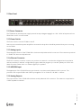
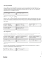
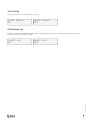
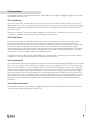
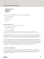
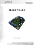
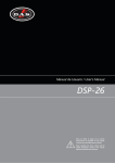
TEOd8
Professional Loudspeaker Management System
User Manual
Warranty
All IDEA products are guaranteed against any manufacturing defect for a period of 2 years from date of purchase.
The guarantee excludes damage from incorrect use of the product.
Any guarantee repair, replacement and servicing must be exclusively done by the factory or any of authorized service
centers.
Do not open or intend to repair the product; otherwise servicing and replacement will not be applicable for guarantee repair.
Return the damaged unit, at shipper’s risk and freight prepaid, with a copy of the purchase invoice in order to claim guarantee
service or replacement to the nearest service center or, when required by the manufacturer, to IDEA headquarters at:
UM_TEOd8_v1_DEF
I MAS D Electroacústica SL
Pol. A Trabe 28-20
15350 Cedeira (A Coruña)
Galicia - Spain
3
Safety Instructions
PLEASE, FOR YOUR PROTECTION READ THE FOLLOWING:
• This device shall not be exposed to dripping or splashing liquid and no object filled with liquid, such as vases, shall be
placed on the apparatus.
• Clean only with a dry cloth.
• Do not block any ventilation openings.
• Do not install near any heat sources such as radiators, heat registers, stoves or other devices that produce
heat.
• Only use the accessories specifies by the manufacturer.
• Unplug this device during lightning storms or when unused for long periods of time.
• Do not defeat the safety purpose of the polarized or grounding-type plug.
• A polarized plug has two blades with one wider than the other.
• A grounding type plug has two blades and a third grounding prong.
• The wide blade or third prong is provided for your safety.
• If the provided plug does not fit your outlet, consult an electrician for replacement of the obsolete outlet.
• Protect the power cord from being walked on or pinched particularly at plugs, convenience receptacles, and
the point where they exit from the apparatus.
• Refer all servicing to qualified service personnel.
• Servicing is required when the device has been damaged in any way, such as power-supply cord or plug is
damaged, liquid has been spilled or objects have fallen into it, the device has been exposed to rain or moisture,
does not operate normally or has been dropped.
• The symbols shown above are internationally accepted symbols that warn of potential hazards with electrical
products. The lightning flash with arrow point in an equilateral triangle means that there are dangerous
voltages present within the processor.
• The exclamation point in an equilateral triangle indicates that it is necessary for the user to refer to the
owner’s manual.
• These symbols warn that there are no user serviceable parts inside the processor.
• Do not open the processor.
• Do not attempt to service the processor yourself.
• Refer all servicing to qualified personnel.
• Opening the chassis for any reason will void the manufacturer’s warranty.
• Do not get the processor wet.
• If liquid is spilled on the processor, shut it off immediately and take it to a dealer for service.
UM_TEOd8_v1_DEF
!
4
POWER ON/OFF SWITCH
If the equipment has a Power switch, the Power switch used in this piece of equipment DOES NOT break the connection from
the mains.
MAINS DISCONNECT
The plug shall remain readily operable.
For rack mount or installation where plug is not accessible, an all-pole mains switch with a contact separation of at least 3
mm in each pole shall be incorporated into the electrical installation of the rack or building.
FOR PRODUCTS EQUIPPED WITH EXTERNALLY ACCESSIBLE FUSE RECEPTACLE
Replace fuse with same type and rating only.
MULTIPLE-INPUT VOLTAGE
This equipment may require the use of a different line cord, attachment plug, or both, depending on the available power
source at installation.
Connect this equipment only to the power source indicated on the equipment rear panel.
To reduce the risk of fire or electric shock, refer servicing to qualified service personnel or equivalent.
If connected to 240V supply, a suitable CSA/UL certified power cord shall be used for this supply.
This equipment is intended for rack mount use only.
THIS APPLIANCE SHALL BE CONNECTED TO A MAINS SOCKET OUTLET WITH A PROTECTIVE EARTHING CONNECTION.
The cores in the mains lead are colored in accordance with the following code:
GREEN and YELLOW - Earth
BLUE - Neutral
BROWN - Live
As colors of the cores in the mains lead of this appliance may not correspond with the colored markings identifying the
terminals in your plug, proceed as follows: The core which is colored green and yellow must be connected to the terminal in
the plug marked with the letter E, or with the earth symbol, or colored green, or green and yellow.
The blue core must be connected to the terminal marked N or colored black.
The brown core must be connected to the terminal marked L or colored red.
This equipment may require the use of a different line cord, attachment plug, or both, depending on the available power
source at installation.
If the attachment plug needs to be changed, refer servicing to qualified service personnel who should refer to the table below.
The green/yellow wire shall be connected directly to the processor’s chassis.
UM_TEOd8_v1_DEF
WARNING: If the ground is defeated, certain fault conditions in the processor or in the system to which it is connected can
result in full line voltage between chassis and earth ground.
Severe injury or death can then result if the chassis and earth ground are touched simultaneously.
5
1. Overview of Connectors and Controls
In addition to the available features described in this manual, you also have the option of controlling the
processor with a PC or MAC from a remote location over your network or via a USB cable.
IDEA DSPControl software is available for download at www.ideaproaudio.com/resources/downloads for MAC
OSX and PC running Windows XP and Windows7.
1.1.Front Panel
1.1.1.USB Connector
The USB connector is used to connect the TEOd8 to a PC or MAC. It can then be configured and controlled in real
time with the freely available PC and MAC configuration program. With this program you can also update your
DSP to the latest firmware. Please check our website regularly for updates.
1.1.2.Input VU Meters
There are 4 independent input meters available. The LEDs indicate: Signal (-48dBu), -6dBu, Limit and Clip. These
meters refer to the absolute input level, multiplied by the input gain. The Limit LED lights when any gain reduction
is taking place in that channel. The CLIP LED lights when the input level reaches +22dBu.
1.1.3.Function Buttons
The function buttons allow direct access to all editing and navigating functions. See section three for a detailed
description on the functions of each of these buttons.
1.1.4.Rotary Encoder
The rotary encoder is used to scroll through the menu items by pushing it, and to adjust values by rotating it.
When values are changed, the DSP is updated in real-time.
1.1.5.Output VU Meters
There are 8 independent output meters available. The LEDs indicate: Signal (-48dBu), -6dBu, Limit and Clip. The
indication refers to the output level w.r.t. The threshold of the output peak limiter. The Limit LED lights when any
gain reduction is taking place in that channel. The CLIP LED lights when more than 12dB of gain reduction is taking
place.
1.1.6.Output Mute Buttons
UM_TEOd8_v1_DEF
The 8 output mute buttons are used for independently muting each output.
6
1.2.Rear Panel
1.2.1.Power Connector
The TEOd8 has an internal power supply that will accept voltages ranging from 110V - 240V at frequencies from
50Hz-60Hz. An IEC cord is included.
1.2.2.Power Switch
The Power Switch turns the TEOd8 on and off.
Note: we recommend that power amplifiers connected to the product should be powered down prior to turning
on the TEOd8.
1.2.3.Analog inputs
The analog input section of the TEOd8 offers 4 electronically balanced XLR connectors. The maximum input level
is +23dBu max, electronically balanced.
1.2.4.Ethernet Connector
The RJ-45 connector is used to connect your product to a network. It can then be configured and controlled in
real time with the PC and MAC configuration program. With this program you can also update your DSP to the
latest firmware. Please check our website regularly for updates.
1.2.5.AES/EBU Input
The digital input of the TEOd8 offers an input channel on an electronically balanced XLR connector. The
processor will accept AES/EBU and S/PDIF input signals of 16 to 24 bit 44.1, 48, 88.2, or 96kHz.
1.2.6.Analog Outputs
UM_TEOd8_v1_DEF
The output section of the TEOd8 offers 8 electronically balanced XLR connectors. The maximum output level is
+12dBu, impedance matched.
7
2. Getting Started
2.1.Connections
2.1.1.Signal Connections
When setting up your processor, make connections as follows:
- Do not power the unit until the input and output connector are plugged.
- Connect the output(s) from the sound source (mixer) to the Ch. 1 XLR input connector (mono) or both, Ch. 1 and Ch. 2 XLR
input connectors (stereo).
- Connect the output XLR connector(s) to the input connector(s) of the selected power amplifier(s).
- Always make sure that your power amps are the last item turned on and the first turned off.
Once all of the connections have been made, and the device is powered up, you can navigate through the entire signal path of
your processor from the front panel.
The display provides you with a clear and concise overview of each aspect of the signal path from the input (left side of
display) to the output section (right side of display).
2.1.2.Remote Monitoring and Control
For the quickest and easiest results we recommend to install and use the PC or MAC configuration software. It provides a
complete and comprehensive tool to make your loudspeaker configuration settings, and to manage your presets.
When
connecting the unit via USB, make sure to connect it directly to your computer or to use a USB hub that supports USB 1.0.
If you have problems with the USB connection, please refer to the Installation Guide for details on how to install the proper
driver.
When connecting the unit via an Ethernet network, you have several options. The PC/MAC application has an auto-discovery
tool that will automatically connect to any unit found on the network.
Please refer to the Software Manual available on our
website for details on the control software.
2.1.2.1.Standard DHCP Network
For the easiest connection, use a standard Ethernet Router, plug in the unit and your computer, and the connection should be
made automatically. Standard routers have a DHCP server built in and enabled. A DHCP server assigns a network address to
your computer and to the TEOd8, allowing them to connect automatically.
2.1.2.2.Connection Without DHCP server
Alternatively, you can use a direct (cross) cable or a simple Ethernet Switch to connect the unit to your PC or
UM_TEOd8_v1_DEF
MAC. Please note that in this case, especially Windows computers may take up to several minutes to assign themselves a
network address (indicated by the text: “This connection has limited or no connectivity”). The computer and the TEOd8 both
will assign themselves a network address in the ZeroConfig range (169.254.0.0 - 169.254.255.255), and the TEOd8 will be
discovered automatically by the PC/MAC application. To facilitate connections without DHCP router, it may be convenient to
set your computer to a fixed IP address. If you do this, please choose any address in the ZeroConfig range, and set the subnet
mask to 255.255.0.0.
8
2.1.2.3.Fixed IP address
It is also possible to set a fixed IP address and subnet mask for the TEOd8. WARNING: If you set a wrong
address (in a different range than your computer), you may not be able to connect anymore. It is STRONGLY
RECOMMENDED to consult a system administrator before making such settings.
2.1.2.4.Firewall
After starting the software application for the first time, your computer may ask you to allow or block the
application access to the network. Please make sure to allow this; if there is a firewall between the application
and the TEOd8, the application will not find the TEOd8.
2.2.System Setup and Gain Structure
This product offers a wide range of tools for sound system design and setup. These tools can make your
system more efficient and better sounding, but to get the best possible sound it is important to use these tools
properly.
The following section explains how to maximize system gain and how to use the limiters to protect
your amplifiers from clipping. In traditional system design, the output of your console would be routed to a
system EQ, a compressor, and a crossover with output level control. From the crossover, there may be additional
filters that are employed to improve the response of your speakers. There may also be limiters set up to keep
your amplifiers from going into clipping and protect your speakers from the hazards of a clipped signal. Your
amplifiers play a vital role in system setup, because they are last device in the chain before your speakers and
offer the greatest amount of gain. If your limiters and amplifiers are incorrectly setup you will not be using your
system to its fullest potential and could result in damage to your speakers.
To ensure an optimal gain structure:
Play a signal at the nominal level from your mixing desk, and set the input gain of your processor to 0.
Set the crossovers that you want to use, while keeping the output gains also at 0.
With DISCONNECTED loudspeakers, turn up the volume of the power amplifiers entirely clockwise (full volume).
Now reduce the output gain and / or the output limiter setting to get the desired gain, so that the amplifier is just
clipping and the built-in limiters of your processor are just limiting. If the amplifier does not have a built-in clip
limiter, set your processor’s limiter so that the amplifier does not clip.
Now turn down the volume of the power amplifiers, connect your speakers, and slowly increase the volume
while checking the sound.
If there are no other issues, there should be distortion-free sound, and the limiter LEDs are flashing or off, but
not continuously on. If they are continuously on, reduce the output gain of your processor.
UM_TEOd8_v1_DEF
If you can not reach enough signal level, increase the processor’s input gain or turn up the level from your mixing
desk.
9
3.Setup And Operation
Before plugging the processor in, always make sure that the power supply matches the product specification voltage. Install
this device on a flat, stable surface. Do not supply power before all components of the system are set up and connected
properly. Make sure to power-up your device before your power amplifiers are switched on in order to avoid transients, which
could damage you.
3.1.System Check
After connecting all cables, you should mute all outputs first or turn the gain/level setting on your amplifiers to minimum.
Activate the HF-outputs first. In case of wrong cabling, High Frequency (HF) audio signals will come out of bass-speakers that
cannot be harmed this way. Vice versa, the Low Frequency (LF) audio signals would destroy your HF-speakers.
3.2.Input Setup
Press the Channel Up or Down button to select the input channel you wish to edit. Make the first settings with the output
turned low or muted.
To toggle through the different menus, press the Item Up or Item Down buttons.
3.2.1.Gain
Adjust the gain by dialing the rotary encoder. The gain is adjusted in steps of 0.25dB. Smaller steps (0.01dB) can be set via the
PC or MAC IDEA DSPControl software.
In AB Gain
-2.25dB
3.2.2.Input Selection
Select the source (Analog or AES/EBU) by rotating the encoder.
In AB Input
Analog
In AB Input
AES/EBU
3.2.3.Delay
Set the delay time by turning the encoder. Select the displayed unit (ms or s, mm or m, feet, inches, or mils) by pushing the
encoder.
In AB Delay
100.23m
In AB Delay
244.5Feet
UM_TEOd8_v1_DEF
In AB Delay
1.02ms
10
3.2.4.Low Pass Filter
Adjust the Low Pass Filter frequency by turning the rotary encoder. You can switch the low pass filter off by turning the
rotary encoder up (clockwise) until the frequency passes 20kHz.
Press the rotary encoder to change the filter type. Select the type by turning the rotary encoder. You can choose from:
Butterworth 6dB, Bessel 6dB, Butterworth 12dB, Bessel 12dB, Linkwitz Riley12dB, Butterworth 18dB, Bessel 18dB, Butterworth
24dB and Bessel 24dB. Higher Order filters may be set by adding filter sections in the PEQ blocks (see below).
In AB Low Pass
Freq: 14500Hz
In AB Low Pass
Type: But24
3.2.5.High Pass Filter
Adjust the high pass frequency by dialing the rotary encoder. You can switch the high pass filter off by dialing the rotary
encoder down (counterclockwise) until the frequency passes 20Hz.
Press the rotary encoder to change the filter type. Select the type by turning the rotary encoder. You can choose from:
Butterworth 6dB, Bessel 6dB, Butterworth 12dB, Bessel 12dB, Linkwitz Riley12dB, Butterworth 18dB, Bessel 18dB, Butterworth
24dB and Bessel 24dB. Higher order filters may be set by adding filter sections in the PEQ blocks (see below).
In AB High Pass
Freq: 34Hz
In AB High Pass
Type: Bes12
3.2.6.Parametric Equalizer (PEQ)
There are ten bands of parametric equalization. Each band can be adjusted freely over the complete frequency range of 20Hz
to 20kHz. Adjust the frequency by dialing the rotary encoder.
Press the rotary encoder to select the parameters. The available parameters are: Frequency (20Hz to 20kHz), Gain (-12dB to
+12dB), Q (0.2 to 25), Enabled (On or Off), Type (Bell, High Shelf, Low Shelf, Notch, All Pass, Band Pass, High Pass, Low Pass).
For the Shelving filters, the Q value sets the steepness of the filter in dB/Oct.
In AB PEQ 5
Gain: -7.
75dB
In AB PEQ 5
Type: Bell
In AB PEQ 5
Enabled: On
In AB PEQ 5
Q:
1.5
UM_TEOd8_v1_DEF
In AB PEQ 5
Freq: 14500Hz
11
3.2.7.Compressor
The compressor is a true RMS compressor. Turn the rotary encoder to set the threshold. Press the rotary encoder to select
the parameters. The available parameters are: Threshold, Attack, Hold, Release, Ratio, and Makeup Gain.
In AB Compressor
Thr.: 23.00dBu
In AB Compressor
Att.: 50ms
In AB Compressor
Hold: 10ms
In AB Compressor
Rel.: 500ms
In AB Compressor
Ratio.: 1:4.5
In AB Compressor
Gain: 4.75
3.2.8.Limiter
The limiter is a zero-attack peak limiter. Only the threshold and release can be set. Press the rotary encoder to select the
parameters. The release value is displayed in dB per second.
In AB Limiter
Thr.: 23.00dBu
In AB Limiter
Rel.: 50dB/s
3.2.9.Channel Link
By linking 2 channels, the settings are guaranteed to be identical for both channels, except for mixer and mute. Turn the
encoder to set the Channel Link on or off.
In AB Limiter
Off
UM_TEOd8_v1_DEF
In AB Limiter
On
12
3.3.Output Setup
Press the Channel Up or Down button to select the output channel you wish to edit. Make the first settings with the output
turned low or muted.
To toggle through the different menus, press the Item Up or Item Down buttons.
3.3.1.Gain
Adjust the gain by dialing the rotary encoder. The gain is adjusted in steps of 0.25dB. Smaller steps (0.01dB) can be set via the
PC or MAC interface.
Out12 Gain
-2.25dB
3.3.2.Mixer
Turn the rotary encoder to mix the signal from the selected input to the selected output. Push the rotary encoder to select
the input. Attention: The mixer is only available while the outputs are not linked by Channel Link. If the channels are linked, the
mixer will be skipped.
Out1 Mixer
In A: -6dB
Out1 Mixer
In B: Off
3.3.3.Delay
Set the delay time by turning the encoder. Select the displayed unit (ms or s, mm or m, feet, inches, or mils) by pushing the
encoder.
Out12 Delay
1.020ms
Out12 Delay
100.23m
Out12 Delay
244.5Feet
3.3.4.Low Pass Filter
Adjust the Low Pass Filter frequency by turning the rotary encoder. You can switch the low pass filter off by turning the
rotary encoder up (clockwise) until the frequency passes 20kHz.
Press the rotary encoder to change the filter type. Select
the type by turning the rotary encoder. You can choose from: Butterworth 6dB, Bessel 6dB, Butterworth 12dB, Bessel 12dB,
Linkwitz Riley12dB, Butterworth 18dB, Bessel 18dB, Butterworth 24dB and Bessel 24dB. Higher order filters may be set by
adding filter sections in the PEQ blocks (see below).
Out12 Low Pass
Type: But24
UM_TEOd8_v1_DEF
Out12 Low Pass
Freq: 14500Hz
13
3.3.5.High Pass Filter
Adjust the high pass frequency by dialing the rotary encoder. You can switch the high pass filter off by dialing the rotary
encoder down (counterclockwise) until the frequency passes 20Hz.
Press the rotary encoder to change the filter type. Select
the type by turning the rotary encoder. You can choose from: Butterworth 6dB, Bessel 6dB, Butterworth 12dB, Bessel 12dB,
Linkwitz Riley12dB, Butterworth 18dB, Bessel 18dB, Butterworth 24dB and Bessel 24dB. Higher order filters may be set by
adding filter sections in the PEQ blocks (see below).
Out12 High Pass
Freq: 34Hz
Out12 High Pass
Type: Bes12
3.3.6.Parametric Equalizer (PEQ)
There are ten bands of parametric equalization. Each band can be adjusted freely over the complete frequency range of 20Hz
to 20kHz. Adjust the frequency by dialing the rotary encoder.
Press the rotary encoder to select the parameters. The available
parameters are: Frequency (20Hz to 20kHz), Gain (-12dB to +12dB), Q (0.2 to 25), Enabled (On or Off), Type (Bell, High Shelf,
Low Shelf, Notch, All Pass, Band Pass, High Pass, Low Pass). For the Shelving filters, the Q value sets the steepness of the
filter in dB/Oct.
Out12 PEQ 5
Freq: 14500Hz
Out12 PEQ 5
Gain: -7.5dB
Out12 PEQ 5
Type: Bell
Out12 PEQ 5
Enabled: On
Out12 PEQ 5
Q:
1.5
3.3.7.Compressor
The compressor is a true RMS compressor. Turn the rotary encoder to set the threshold. Press the rotary encoder to select
the parameters. The available parameters are: Threshold, Attack, Hold, Release, Ratio, and Makeup Gain.
Out12 Compressor
Thr.: 23.00dBu
Out12 Compressor
Att.: 50ms
Out12 Compressor
Hold: 10ms
Out12 Compressor
Res.: 500ms
Out12 Compressor
Ratio: 1:4.5
Out12 Compressor
Gain: 4.75dB
3.3.8.Limiter
The limiter is a zero-attack peak limiter. Only the threshold and release can be set. Press the rotary encoder to select the
parameters. The release value is displayed in dB per second.
Out12 Limiter
Rel.: 50dB/s
UM_TEOd8_v1_DEF
Out12 Limiter
Thr.: 23.00dBu
14
3.3.9. Polarity
Turn the rotary encoder to switch polarity on or off.
Out12 Invert
On
Out12 Invert
Off
3.3.10.Channel Link
By linking 2 channels, the settings are guaranteed to be identical for both channels, except for mixer and mute. Turn the
encoder to set the Channel Link on or off.
Out12 Link
Off
UM_TEOd8_v1_DEF
Out12 Link
On
15
3.4.System Menu
Push the Menu button to enter the system menu. Push the Menu button again to toggle through the menu items.
The available menu items are:
3.4.1.Load Preset
Turn the rotary encoder to select the preset you wish to load. Push the rotary encoder to select it, then turn it
again to select “YES” and confirm again by pushing the rotary encoder knob. The preset is loaded and all settings
are applied immediately. All settings that were in the unit prior to loading the preset will be erased. This action
can not be undone.
The presets contain all filter, dynamics, gain settings etc. Presets do NOT contain the name of the unit, network
configuration, automatic standby delay, user access rights and passwords.
3.4.2.Save Preset
Turn the rotary encoder to select the location of the preset. If that location is not empty, the preset in that
location will be overwritten. This action can not be undone.
The system will ask you to give a name to the
preset name. Select a character in the cursor position by turning the rotary encoder; pushing the rotary encoder
confirms the character selected and moves the cursor to the next character to edit. Pushing the exit/ESC
button erases the last confirmed character. Once the name is set up, push the menu button again. If you want to
continue storing the preset, select Yes by turning the rotary encoder and confirm by pushing it. To cancel, push
the exit button. Now your preset is saved in the selected location.
The presets contain all filter, dynamics, gain settings etc. Presets do NOT contain the name of the unit, network
configuration, automatic standby delay, user access rights and passwords.
3.4.3.Access Level
The TEOd8 has the option of locking away the front panel controls to avoid tampering of settings by unauthorized
persons. To lock the unit, select “Locked” by turning the rotary encoder, and push it to confirm. The system will
ask you to enter a password. Select a character in the cursor position by turning the rotary encoder; pushing the
rotary encoder confirms the character selected and moves the cursor to the next character to edit. Pushing the
exit/ESC button erases the last confirmed character. Once the password is set up, push the menu button again
and the unit will be locked.
ATTENTION: Make sure to remember the password! When the unit is locked and you
forgot the password, it is not possible to unlock it without contacting your local service representative.
To unlock
the unit select “Unlocked” and enter the password. The password is automatically checked after each entered
character, and the unit will exit the system menu when the password is confirmed.
The default password is
“Password”.
3.4.4.Version Information
UM_TEOd8_v1_DEF
By pushing the rotary encoder, the display toggles through some version information about the unit, as well as
some parameters like IP address, MAC address etc.
16
Appendix A: Declaration Of Conformity
AllDSP GmbH & Co. KG
Spengler Str. 6
59067 Hamm
Germany
Declares that the product IDEA TEOd8 conforms to the following Specifications:
• Safety: IEC 60065 -01+Amd 1
• EMC : EN 55022:2006
• EN 55103 -1, -2 2008
• EN 55024:1998
• FCC Part 15
Supplementary Information
The product herewith complies with the requirements of the:
• Low Voltage Directive 2006/95/EC
• EMC Directive 2004/108/EC
• RoHS Directive 2002/95/EC
• WEEE Directive 2002/96/EC
With regard to Directive 2005/32/EC and EC Regulation 1275/2008 of 17 December 2008, this product is
designed, produced, and classified as Professional Audio Equipment and thus is exempt from this Directive.
A molded mains plug that has been cut off from the cord is unsafe. Discard the mains plug at a suitable disposal
facility. NEVER UNDER ANY CIRCUMSTANCES SHOULD YOU INSERT A DAMAGED OR CUT MAINS PLUG INTO A 13
AMP POWER SOCKET. Do not use the mains plug without the fuse cover in place. Replacement fuse covers can be
obtained from your local retailer. Replacement fuses are 13 amps and MUST be ASTA approved to BS1362.
If you want to dispose this product, do not mix it with general household waste. There is a separate collection
system for used electronic products in accordance with legislation that requires proper treatment, recovery and
recycling. Private household in the 25 member states of the EU, in Switzerland and Norway may return their used
electronic products free of charge to designated collection facilities or to a retailer (if you purchase a similar new
one). For Countries not mentioned above, please contact your local authorities for a correct method of disposal.
By doing so you will ensure that your disposed product undergoes the necessary treatment, recovery and
recycling and thus prevent potential negative effects on the environment and human health.
This device complies with part 15 of the FCC Rules and the Product Specifications noted on the Declaration of
Conformity. Operation is subject to the following two conditions:
- this device may not cause harmful interference,
and
- this device must accept any interference received, including interference that may cause undesired
operation. Operation of this processor within significant electromagnetic fields should be avoided.
- Use only
shielded interconnecting cables.
17
UM_TEOd8_v1_DEF
ELECTROMAGNETIC COMPATIBILITY
www.ideaproaudio.com
©2015 - I MAS D Electroacústica SL - Av. Constitución 5-9 46009 VALENCIA