1
novaNet OPC Server
novaNet OPC Server
OPC Server for Sauter
EY3600 System
7001063003 T3
This description corresponds to the current
program version 2.2.0.11 Changes may be
made at any time without prior notice.
7001063003 T3
Sauter Systems
1
novaNet OPC Server
2
7001063003 T3
Sauter Systems
novaNet OPC Server
0
Inhaltsverzeichnis
Inhaltsverzeichnis
Inhaltsverzeichnis ........................................................................................................ 3
1
Purpose .................................................................................................................. 7
2
Description ............................................................................................................. 9
2.1 OPC Server ......................................................................................................... 9
2.2 Time program editor component .......................................................................... 9
3
Installation............................................................................................................ 11
3.1
3.2
4
Quick start ............................................................................................................ 15
4.1
4.2
4.3
5
List of installed files of the OPC server ........................................................... 13
List of installed OPC proxy files ...................................................................... 14
Install one or more modems ........................................................................... 15
Connect the equipments ................................................................................. 15
Declare the equipments .................................................................................. 15
Usage.................................................................................................................... 21
5.1 OPC server parameters.................................................................................. 21
5.2 Trace utility for the visualisation of the trace messages .................................. 23
5.3 Client application: OPC server declaration..................................................... 23
5.4 Client application: OPC items declaration ...................................................... 24
5.4.1 General Items.......................................................................................... 24
5.4.2 Items for communication line (modem) .................................................... 25
5.4.3 Items for router ........................................................................................ 25
5.4.4 Items for automation station .................................................................... 26
5.4.5 Items for the addresses of the automation station (MFA)......................... 26
5.4.6 Items to read from historical database..................................................... 27
5.4.7 Items for direct memory access of the automation station ....................... 28
5.4.7.1 Access a column of DW ................................................................... 29
5.4.7.2 Access a row of DW......................................................................... 29
5.4.7.3 Access a DW in decimal format........................................................ 29
5.4.7.4 Access a DW in hexadecimal format ................................................ 29
5.4.7.5 Access a DW in measure format (real)............................................. 30
5.5 Usage of items for connection state................................................................ 30
5.6 Usage of Remote OPC (DCOM) ..................................................................... 31
5.7 Client application : Usage of the time program control .................................... 32
5.7.1 Usage of the control ................................................................................ 33
5.7.1.1 First page ......................................................................................... 33
5.7.1.2 Dialog to edit a time program ........................................................... 34
7001063003 T3
Sauter Systems
3
novaNet OPC Server
0
Inhaltsverzeichnis
5.7.1.3
5.7.1.4
5.7.1.5
5.7.1.6
6
Dialog to edit a analogue command ..................................................35
Dialog to edit a binary command.......................................................36
Operations on main page..................................................................37
Edit of the calendar ...........................................................................38
Operation of OPC Server......................................................................................39
6.1
6.2
6.3
6.4
Read and write ................................................................................................39
Presence test of the automation station...........................................................40
Information with spontaneous messages.........................................................40
Information with polling requests .....................................................................41
A1 List of all items of the OPC server.......................................................................43
A2 History of changes ...............................................................................................47
Version 2.1.0.0 to 2.2.0.4..........................................................................................47
Version 2.2.0.4 to 2.2.0.5..........................................................................................47
Version 2.2.0.5 to 2.2.0.6..........................................................................................47
Version 2.2.0.6 to 2.2.0.7..........................................................................................50
Version 2.2.0.7 to 2.2.0.8..........................................................................................50
Version 2.2.0.8 to 2.2.0.9..........................................................................................51
Version 2.2.0.9 to 2.2.0.10........................................................................................51
Version 2.2.0.10 to 2.2.0.11......................................................................................51
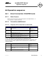
A3 Operation sequence .............................................................................................53
A3.1 Direct Connection: ROUTER mode .................................................................53
A3.1.1 Start of server ..........................................................................................53
A3.1.2 Connection establishment ........................................................................53
A3.1.2.1 Sequence of the connection in router mode ......................................53
A3.1.3 Disconnection ..........................................................................................54
A3.1.4 Connection error ......................................................................................54
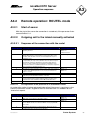
A3.2 Remote operation: ROUTEL mode..................................................................55
A3.2.1 Start of server ..........................................................................................55
A3.2.2 Outgoing call to the island manually activated..........................................55
A3.2.2.1 Sequence of the connection with the routel.......................................55
A3.2.2.2 Disconnection ...................................................................................56
A3.2.2.3 Connection error ...............................................................................56
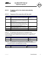
A3.2.3 Outgoing call to the island automatically activated ..................................57
A3.2.3.1 Sequence of the connection with the routel.......................................57
A3.2.3.2 Disconnection ...................................................................................58
A3.2.3.3 Connection error ...............................................................................58
A3.2.4 Incoming call from the island ....................................................................58
A3.2.4.1 Sequence of the connection with the routel.......................................58
A3.2.4.2 Disconnection ...................................................................................59
4
7001063003 T3
Sauter Systems
novaNet OPC Server
0
Inhaltsverzeichnis
A3.2.4.3 Connection error .............................................................................. 59
A4 Registry of the OPC server.................................................................................. 61
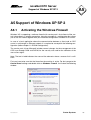
A5 Support of Windows XP SP 2.............................................................................. 65
A5.1 Activating the Windows Firewall...................................................................... 65
A5.1.1 Adding exceptions ................................................................................... 66
A5.1.2 Access rights for the network ports.......................................................... 67
A5.2 DCOM configuration ....................................................................................... 67
A5.2.1 Launch of DCOMCnfg.exe....................................................................... 67
A5.2.2 Adding anonymous user accounts........................................................... 69
A5.2.3 Launch permission .................................................................................. 71
A6 Recording of PC-291 telegrams .......................................................................... 73
A6.1 Description of the recording function............................................................... 73
A6.2 Example of a record........................................................................................ 73
A7 Bibliography......................................................................................................... 75
7001063003 T3
Sauter Systems
5
novaNet OPC Server
0
Inhaltsverzeichnis
Trademarks
Registered trademarks and product designations of various companies and manufacturers are not specifically shown in this manual, but a summary of them is given here.
Microsoft, Windows, MS-DOS
Microsoft Office
Microsoft Excel
Microsoft Access
Microsoft Word
Acrobat Reader
Trademark of Microsoft Corporation
Trademark of Microsoft Corporation
Trademark of Microsoft Corporation
Trademark of Microsoft Corporation
Trademark of Microsoft Corporation
Adobe Systems Incorporated
OPC
Trademark of the OPC Foundation
Ethernet
Intel, Pentium
Trademark of the Xerox Corporation
Trademark of the Intel Corporation
All other brand or product names mentioned in the manual are trademarks and/or registered trademarks of the owners of the respective rights.
6
7001063003 T3
Sauter Systems
novaNet OPC Server
1
Purpose
1 Purpose
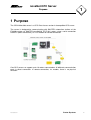
The OPCAsNovaNet server is a OPC Data Access version 2.0 compatible OPC server.
The server is designed for communicating with SAUTER automation stations of the
EY3600 system via SAUTER novaNet291 (EYZ 291) router, using a serial connection
RS232-C (direct connection), or via a modem for remote connection.
One OPC server can support up to 16 routers connected on 16 different communication
ports in direct connection. In remote connection, via modem, there is no physical
limitation.
7001063003 T3
Sauter Systems
7
novaNet OPC Server
1
8
Purpose
7001063003 T3
Sauter Systems
novaNet OPC Server
2
Description
2 Description
OPCAsNovaNet comes in two components : an OPC server and a time program editor
component.
2.1 OPC Server
The OPC server is with the standard OPC Data Access 2.0 compatible. It is supporting
'custom' interfaces, including the optional interfaces defined in the standard. Automation
stations can be addressed using OPC items (refer to namespace definition below).
Since version 2.2.0.5, server is dealing with the modem communication lines, independently from the routers. In other words, list of usable communications lines are simply
declared (for sure, one modem needs to be installed for each declared communication
line). The server will then assign a communication line to a router, as needed. It is possible to reserve some communication lines for incoming calls only (response only modus).
The server is composed of an executable file called OPCAsNovaNetTrace.exe and a
configuration file called OPCAsNovaNet.ini.
The configuration file contains all functional parameters needed by the server.
2.2 Time program editor component
The time program editor component is delivered as an ActiveX component, therefore it
can be integrated in any application supporting the OLE object. It is allowing the edition
of the time programs and calendars of all automation stations controlled by the OPC
server.
This component is delivered in two versions :
TimeProgramOcx.dll
TimeProgramOcxFra.dll
7001063003 T3
: English version
: French version
Sauter Systems
9
novaNet OPC Server
2
10
Description
7001063003 T3
Sauter Systems
novaNet OPC Server
3
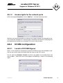
Installation
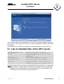
3 Installation
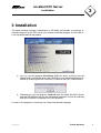
The whole software package is delivered on a CD-ROM, and includes an automatic installation program for the OPC server and a driver installation program for the USB security key delivered with the product.
1)
You can start the program hinstall.exe (USB key driver) manually from the
zipped folder \Util\Hinstall.zip on the CD-ROM or use the following shown interface by choosing INSTALL PRODUCTS and then INSTALL USB DRIVER.
2)
Following you start the program setup.exe from the folder \Bin\OPC Server\
from the CD-ROM or you can use the general installation surface by selecting
INSTALL PRODUCTS and INSTALL OPC SERVER.
As soon as the program is started you can choose the desired language.
7001063003 T3
Sauter Systems
11
novaNet OPC Server
3
Installation
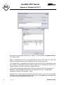
A dialog window shows you the version number of your OPC Server.
Click on 'Next'.
12
7001063003 T3
Sauter Systems
novaNet OPC Server
3
Installation
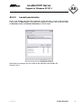
You have the choice of two setup types: the first will install the complete software on
your system or the second will allow you to install the different available components
customized.
At that moment the installation is finished you can parameterise the initialisation files.
3.1 List of installed files of the OPC server
OPCASNovaNetRemoteTrace.exe
OPCASENovaNet.ini
Net1.ini
OCSTrace.exe
TimeProgramOcx.dll
TimeProgramOcxFra.dll
OPC Library
: OPC server executable main program
: example of OPC server configuration file
: example of definition file for data points
with spontaneous
messaging
: trace display program
: English time program editor component
: French time program editor component
: OPC Core Components 2.00 Redistributable
2.20.msi
Installation program for OPC common files
Note: Never move this files manually to another folder after installation. If it is requested
to place them in another folder, uninstall the whole software (using install/uninstall
programs icon in configuration panel), and then reinstall it in the new folder. Only
one copy of this files can exist on a workstation (PC).
7001063003 T3
Sauter Systems
13
novaNet OPC Server
3
Installation
3.2 List of installed OPC proxy files
OPCEnum.exe
OPCComn_ps.dll
OPCProxy.dll
opc_aeps.dll
opcbc_ps.dll
opchda_ps.dll
opcSec_ps.dll
OpcComnRcw.dll
: Navigator for OPC Servers
: Proxy/Stub-DLL for the OPC Common interfaces
: Proxy/Stub-DLL for the OPC Data Access interfaces
: Proxy/Stub-DLL for the OPC Alarm and Event
interfaces
: Proxy/Stub-DLL for the OPC Batch interfaces
: Proxy/Stub-DLL for the OPC Historical Data
Access interfaces
: Proxy/Stub-DLL for the OPC Security and Marshalling interfaces
: .NET interface as Runtime Callable Wrapper
(RCW)
These files are installed in the ./Windows/System32 or . /WinNT/System32 folder. It is
not allowed to move them. If problems occur you can install the program OPC Core
Components 2.00 Redistributable 2.20.msi again.
14
7001063003 T3
Sauter Systems
novaNet OPC Server
4
Quick start
4 Quick start
4.1 Install one or more modems
In the Windows configuration panel, use the 'Add new hardware' wizard to install your
modem(s). Use the drivers delivered by the modem manufacturer.
For each modem, write down the windows identification name. This name has to be
listed as designation of the modem in the configuration file of the server.
Set up the modem parameters as follow, for every installed modem :
Communication rate: 19200 bauds or higher
Number of bits: 8
Number of stops: 1
Parity: none
Stream control: hardware
Attention: make sure this setup is correctly done, since the server will use the windows
settings. It is possible to change the communication rate if the router is setup
in the same manner.
4.2 Connect the equipments
Connect a 291 router to the PC via a serial interface or install a modem using the windows configuration panel.
4.3 Declare the equipments
Open file OPCASNOVANET.INI in NotePad or any other text editor.
In section [ComLines] insert a line for each phone line to be supported. In order to work
with the example application, this name needs to be 'Line1'.
Example:
[ComLines]
Line1
Add a section to describe the modem communication line. Section needs to be named
with the same label as the communication line.
7001063003 T3
Sauter Systems
15
novaNet OPC Server
4
Quick start
Insert line parameters in this section:
Parameter
Description
Device = U.S. Robotics 56K FAX EXT PnP
The device name is the modem name as it appears in the windows
configuration panel. If it is omitted, the server will use the first
available modem.
Put value 1 here, if you want to reserve this line for incoming calls
only. In this case this line is not used for outgoing calls.
1 if the modem should answer incoming calls. In this case the
server answers automatically to all incoming calls on this line.
InboundReserved = 0
Autoanswer = 1
Example:
[Line1]
Device = U.S. Robotics 56K FAX EXT PnP
InboundReserved = 0
Autoanswer = 1
In the [Routers] section, insert a line containing the name of the router. In order to work
with the example application , this needs to be set to 'Net1'.
Example:
[Routers]
Net1
Add another section to describe the router. The section needs to be named as the
router.
In this section , insert the router parameters:
Parameter
Description
PCAddress = aaaaa
ComPort = p
ComSpeed = sssss
aaaa corresponds to the PC address seen from the server.
p is the port number used to communicate with the router.
ssss is the communication rate in bauds.
Is p 0, the server is using a modem for the communication with the router. Each other
value is generating a direct local connection with the corresponding serial port (COM1,
COM2, etc.). A modem communication is not possible if p is bigger than 0. The allocation of the phone calls is managed dynamically by the OPC server.
Note: It is not possible to specify for a island explicitly a modem for outgoing calls if the
hardware configuration of the clients have multiple outgoing modems (administration by
modem pool).
16
7001063003 T3
Sauter Systems
novaNet OPC Server
4
Quick start
In order to communicate via modem, the port number has to be set to 0. Furthermore
the following parameters needs to be set:
Parameter
Description
NetworkID = xxx
xxx is the Routel ID which has been setup in the router with the
configuration program (RoutelPara, HWC).
ppp is the phone number to dial to connect to the modem connected on the router.
PhoneNumber = ppp
Note: the variable PCAddress needs to contain a value compatible with the Routel function, this means 32512 for the first Routel in the network. For a configuration as direct bus the value needs to be 31744.
Add a line to list the automation stations connected to the current router.
Parameter
Description
ASList = xxxx
xxxx is the name chosen for the automation station.
Note: For the application example the name has to be 'AS128'.
For each automation station add a line to describe his address on the ASNovaNet bus.
Example:
[Net1]
PCAddress = 31945
ComPort = 1
ComSpeed = 38400
ASList = AS128
AS128 = 1
For each declared router, create a text file describing the list for all data points with
spontaneous messaging for each automation station. This file needs to be named like
the router, and have the '.INI' extension.
Example: Net1.ini
This file needs to have a section for each declared automation station on the router (just
copy the names from the 'ASList' in file opcasnovanet.ini).
In each section, the number of the data points (MFA) which should be spontaneous is
listed. A value is linked to the number specifying the desired parameterisation:
7001063003 T3
Sauter Systems
17
novaNet OPC Server
4
Quick start
;
=
=
=
=
=
=
=
=
in
x0
x1
x2
x3
x4
x5
x6
x7
router mode and routel mode with disconnected link (calling activation)
: no spontaneous messaging
: spontaneous messaging of analogue value + counter
: spontaneous messaging of binary value + counter
: spontaneous messaging of analogue value + binary + counter
: NovaLink: no spontaneous messaging
: NovaLink: spontaneous messaging of analogue value + counter
: NovaLink: spontaneous messaging of binary value + counter
: NovaLink: spontaneous messaging of analogue value + binary + counter
;
=
=
=
=
=
=
=
in
1y
2y
3y
4y
5y
6y
7y
routel mode during connection
: spontaneous messaging of analogue value + counter
: spontaneous messaging of binary value + counter
: spontaneous messaging of analogue value + binary + counter
: NovaLink: no spontaneous messaging
: NovaLink: spontaneous messaging of analogue value + counter
: NovaLink: spontaneous messaging of binary value + counter
: NovaLink: spontaneous messaging of analogue value + binary + counter
The code for spontaneous messaging is a two-digit value (X, Y). Is the value 0 it is a
indication there is no spontaneous messaging.
•
•
The ones (Y) declare the type for programmed spontaneous messages in the
automation stations in router mode (direct connection) and in routel mode (modem connection) with disconnected line; it allows specification which MFA with a
value change activate a call (dialling).
The tens (X) declare the type for the programmed spontaneous messages in the
automation stations during connection in routel mode; it allows specification
which MFAs are dynamically actualised during connection.
Example of contents:
[AS128]
0 = 1
52 = 20
53 = 22
54 = 2
20 = 0
21 = 0
Explanation:
For the automation station AS128:
18
•
In routel mode MFA 0 is dialling with disconnected link. During connection it will
not be actualised.
In router mode it is in 'spontaneous messaging' mode.
•
In routel mode MFA 52 is not dialling during disconnected link. Only during connection it is in 'spontaneous messaging' mode.
In router mode it is not in 'spontaneous messaging' mode.
7001063003 T3
Sauter Systems
novaNet OPC Server
4
Quick start
•
In routel mode MFA 53 is dialling with disconnected link. During connection it will
be actualised in 'spontaneous messaging' mode.
In router mode it is in 'spontaneous messaging' mode.
•
In routel mode MFA 54 is dialling with disconnected link. During connection it will
not be actualised.
In router mode it is in 'spontaneous messaging' mode.
•
In routel mode MFA 20 is not dialling during disconnected link. Only during connection it is in 'spontaneous messaging' mode.
In router mode it is not in 'spontaneous messaging' mode. It is connected with a
novaLink module.
•
For MFA 21 the spontaneous messages are all deactivated.
In routel mode it is not dialling and during connection it is not actualised.
In router mode it is not in 'spontaneous messaging' mode.
Note :
•
•
•
The content of this file is interpreted at each connection to the router. It is therefore possible to change it while the server is up and running. A manual action to
disconnect/reconnect will allow to reprogram the automation stations.
With the usage of novaLink modules (code=5) the information 'SetpointFeedback.Local' is not transmitted spontaneously. It is necessary to read manually or
to wait on the automatic refresh cycle.
Code 6 and 7 are not used at this time. They are reserved for future development.
7001063003 T3
Sauter Systems
19
novaNet OPC Server
4
20
Quick start
7001063003 T3
Sauter Systems
novaNet OPC Server
5
Usage
5 Usage
Before the OPC server can be used, it is mandatory to define all the functional parameters and declare the list of routers and automation stations to be supported. This is done
by editing file OpcAsNovaNet.ini.
5.1 OPC server parameters
Below an example of the delivered configuration file with the default values, with some
comments:
Note: The values indicated below are those taken into account by the OPC server in the
case where the initialisation file does not carry an explicit declaration of these parameters.
Designation
Description
[Server]
ReadDelay = 2000
This section describes the server parameters
Asynchronous reading delay (in ms). The server will collect all reading requests
during this period of time, and then start a group request on the network.
WriteDelay = 1000
Asynchronous writing delay (in ms). The server will collect all writing requests during
this period of time, and then execute a group request on the network.
StatusPolling = 30000
Polling interval (in ms) for checking the presence of the automation stations. A polling of the online automation stations are just done if the revision of the router/routel
firmware is older than version 'F'.
ReadPolling = 20000
Periodic polling interval (in ms) for the reading items. The periodic polling to read the
items that are not configured to be in spontaneous messaging mode is just done in
router mode. In routel mode the actualisation is just done in spontaneous message
mode or with the manual request through the item 'Refresh'.
ReadMaskDelay = 3000
Update masking time (in ms) for writing operations
ContractTimeout = 5000
Waiting time when executing a request (in ms)
HDBContractTimeout = 15000 Waiting time when executing a historical reading request (in ms)
IgnoreRead = 0
Value 1 means reading request are ignored. Needs to be set to 1 for clients doing a
polling in order to not overload the communication.
AsyncRead = 1
Value 1 means, reading is asynchronous, otherwise reading is synchronous
AsyncWrite = 1
Value 1 means, writing is asynchronous, otherwise writing is synchronous
InactivityTime = 30000
In case of modem connection, time in ms before the line is shut down in case of
inactivity. Note : an integrated scheduler is forcing the shut down after 15 minutes of
inactivity.
PCAddress = 31744
Router address, for incoming calls.
PC address that is assigned to the routel with an incoming call if the EPROM is not
programmed with a valid PC address. This value is used as well for the default value
if there is no specification for each the section [Router]. If the OPC server is configured to be on a direct bus the PC address is 31744.
KeepValid = 1
Value 1, the variables will still be valid in supervision when connection with the
automation stations is shut down. With value 0 all items regarding the automation
stations become invalid with a missing connection. However, the last value stays.
AutoConnect = 1
Value 1, the network is automatically connected on start up, when there is a request
for reading or writing. If value is 0, a manual action for connection is required (only in
routel mode).
TraceLevel = 3
Level of detail for the trace messages. The default value is 3 (shows the service and
error messages). With the value 11 it is possible to show additionally the debugging
messages. The value 15 shows in addition the sent content of the frames.
InboundInactivityTime = 15000 Wait time before hang up during inactivity (expressed in milliseconds) in case of
modem connection for incoming calls.
ManualInactivityTime = 180000 Wait time before hung up during inactivity (expressed in milliseconds) in case of a
modem connection through a call by the user (Item Connect triggered)
NumRetries = 5
Count of dial retries if dial error occurs in routel mode. In router mode the retry to dial
is done as long as the connection request is active.
RetryDelay = 180000
Time interval between two dial retries of the modems (expressed in milliseconds)
ConnectionTimeout = 45000
Wait time of the dial connection of the router with a modem connection (expressed in
7001063003 T3
Sauter Systems
21
novaNet OPC Server
5
Usage
RouterPollingDelay = 15
AutoConnectOnStart = 0
HDBRetrieveTimeout =
1800000
RoutelCommTimeout = 5000
CheckAliveDelay = 3000
ReadQueueSize = 4000
WriteQueueSize = 16000
WatchdogPeriod = 10000
LogTAPIEvents = 0
ChekTAPIPeriod = 180000
NovaNetLogFiles = N,1,1
[Routers]
Net1
;Net2
…
[Net1]
PCAddress = 31744
ComPort = 1
ComSpeed = 38400
IdleDetectionCount = 3
AutoConnectOnStart = 0
CheckAliveMaskDelay = 10000
ASList = AS128,AS200,AS300
AS128 = 128
AS200 = 200
AS300 = 300
…
[Net2]
PCAddress = 32512
ComPort = 2
ComSpeed = 38400
IdleDetectionCount = 3
NetworkID = ILOT1
PhoneNumber = 0123456789
22
7001063003 T3
milliseconds). Is the router not recognised after this time the connection is ended.
Wait time between two request cycles of the router/routel in milliseconds. Increment
this value to slow down the reading flow. In the most cases the default value is
enough.
If 1, the server is trying to connect to all remote islands on start up (exclusively in
routel mode). In the router mode the connection is done always automatically on
start up.
Maximal wait time for the transmission of the historical database values to the OPC
clients. At the end of this time if not all clients have read the HDB values the process
to read the HDB will be reactivated and the HDB is available to be read again.
Timeout of the connection in routel mode. This time can be increased if latency in
the modems exists.
Wait time for the feedback of the automation station with the execution of the 'checkalive'-process (collecting all the automation station available on the bus). The whole
wait time is calculated by this value multiplied with the amount of available automation stations on the bus at time of the request.
Size of the internal read queue file (per controller). Represents the maximum number of read requests in the queue file. This value must be increased if the error
"Read failed: Queue size limit exceeded" appears. This value is identical for all
controllers in the island.
Size of the internal write queue file (for all controllers in the island). Represents the
maximum number of values in the write queue file. This value must be increased if
the error, "Write failed: Queue size limit exceeded" appears.
Defines the watchdog period for monitoring internal server tasks in milliseconds. The
minimum value is 2000 milliseconds.
Allows generation of a log file tracing TAPI events linked to activity of modems for
diagnostics (if value = 1).
Defines the task period for monitoring modems in milliseconds. This task monitors all
free modems and periodically verifies their state.
Can enable the debugging recording for the communication between the OPC
Server and the novaNet291 router. With = Y,24,60 the recording is switched on. It
will create 24 files each has data for 60 minutes.
This section is listing the names of the connected routers.
First router name.
Second router name (invalid in this example because of the semicolon at front)
First router parameters.
PC address for this router (default value); is the server configured in routel mode this
value is 32512.
Communication port number (1 to 16)
Communication rate
Count of consecutive request cycles of the router while no information is reported
during no-load of the network (no data traffic). This parameter is used for acquisition
of the feedback messages in the state for the 'checkalive'-Process.
If 1, the connection to the island is established automatically at start-up of the server
(in routel or router). If this value is absent, the AutoconnectOnStart parameter of the
SERVER section is taken into account for routel mode and an island on direct bus
(router) is automatically connected.
Defines a masking time before router data is taken into account, indicating that the
number of controllers present on the bus has changed. This mask prevents the
launching of CheckAlive procedures when the router returns error data due to a high
volume of transmission on the bus. A zero value disables masking, and status
change data is taken into account immediately.
List of the names of the automation stations (comma separated) to those the router
has access.
Address of the first automation station
Address of the second automation station
Address of the third automation station
Second router parameters
PC address for this router
Communication port number (1 to 16)
Communication rate
Count of consecutive request cycles of the router while no information is reported
during no-load of the network (no data traffic). This parameter is used for acquisition
of the feedback messages in the state for the 'checkalive'-Process.
(Only for Routel) ID of the island how it is coded in Routel (String of up to 16 characters).
(Only for Routel) to dial this number for a connection with the routel for this island.
Sauter Systems
novaNet OPC Server
5
Usage
ASList = AS128,AS200,AS300
AS128 = 128
AS200 = 200
AS300 = 300
…
List of the names of the automation stations (comma separated) to those the router
has access.
Address of the first automation station
Address of the second automation station
Address of the third automation station
Note : The configuration file needs to be located in the folder where the OPC server is
installed.
Up to 16 routers can be declared in direct connection, if so many communication ports
are available. In modem connection there is no physical limitation. The server parameters are valid for most of the applications. It could be necessary to adapt them in some
specific situations (lot of network traffic for example) or to solve compatibility issues.
Only one configuration file can exist on one PC. If different configurations needs to be
used, it will be necessary to use a configuration file library in a different folder.
The list of the names for the automation stations under 'ASList' does not allow to have
spaces. The only allowed separator is the comma.
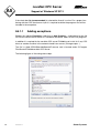
5.2 Trace utility for the visualisation of the
trace messages
Before starting a client application, start the OCSTRACE.EXE program. It will allow the
display of trace and diagnostic messages from the OPC server.
This utility is optional, it will be of help in setup phase as well as for fixing issues. This
utility can be started at any time to display the trace messages from the server.
5.3 Client application: OPC server
declaration
In the client application, create an OPC server instance. The OPCAsNovaNet server is
called:
SAUTER ASNovaNetRemote OPC Server V1.0
The ProgID of the server is: SAUTER.ASNovaNetRemote.1
7001063003 T3
Sauter Systems
23
novaNet OPC Server
5
Usage
5.4 Client application: OPC items
declaration
The communication with the OPC server occurs via items. The item name is representing the information which is addressed. It is composed of different elements assembled
by points. The full name represents a path in the tree structured namespace.
The namespace is a tree structure. The general syntax for items is the following:
RouterName.AutomationStationName.Item
Net1.AS128.MFA000.Measure
e.g.
'RouterName' (e.g. 'Net1') represents the router name as declared in the configuration
file.
'AutomationStationName' (e.g. 'AS128') represents the automation station connected to
the router, as declared in the configuration file.
'Item' (e.g. MFA000.Measure) is the information from the automation station according
to the syntax defined in the namespace.
For further details, refer to namespace in appendix.
5.4.1 General Items
Designation
Description
Traces
Its value is indicating the detail level for the trace messages.
Value is obtained by combining bits :
1 : (bit 0) error message
2 : (bit 1) warning messages
4 : (bit 2) exchange messages (transactions)
8 : (bit 3) diagnostic messages (OPC functions)
Watchdog
WatchdogDate
WatchdogInfo
Example: Value 3 (bit 0 + bit 1, default value) is enabling the
display of error and warning messages. With value 11 it will
show in addition the debugging messages. Value 15 would
show in addition the content of the frames.
This item is positioned at value 1 periodically to the watchdog
frequency if no fault condition has been detected in the
server. It can be periodically reset to 0 by the client for implementing a ‘"Full Watchdog" function.
This item (text format) is positioned at the current date of the
server periodically to the watchdog frequency if no fault
condition has been detected in the server.
This item (text format) displays a text which allows identification of the cause of watchdog activation. In the absence of a
fault condition, it indicates "OK". The causes of activation are
coded as follows:- [ISLAND_NAME(X)] or ISLAND_NAME is the name of the
island and X represents a code identifying the frozen task (R:
router task. D: main task. P: controller task).
- [Server(TAPI)]: task for monitoring frozen modems
WatchdogTest
24
7001063003 T3
- [Server(Update)]: Task for updating a frozen server.
This item (binary format) allows manual activation of the
watchdog for test purposes. The watchdog is activated as
long as this item is at 1. Note: It is not visible in the browser.
Sauter Systems
novaNet OPC Server
5
Usage
5.4.2 Items for communication line (modem)
We suppose THE line is called 'Line1'
Designation
Description
Line1.Name
This item's value will contain the logical name of the line (in
the example it will be 'Line1')
Value is indicating line status as text (in English)
Value is indicating if line is connected or not.
Value contains the dialled number.
Value contains the modem name associated with this line.
Line1.State
Line1.OnLine
Line1.PhoneNumber
Line1.DeviceName
5.4.3 Items for router
WE suppose THE router IS called 'Router1'
Designation
Description
Router1.ComPort
Router1.ComSpeed
Router1.Address
Router1.Connect
Router1.ConnectDate
Router1.OnLine
Router1.OffLine
Value indicates the communication port number which is used.
Value indicates communication rate (in bauds).
Value contains the PC address (novaNet) as seen from the router.
Allows to start or stop the communication with the router.
Value indicates the date of the last connection with the router.
Value indicates if communication with router is ok.
This value changes the status 'True' as soon as the connection with
the router is disconnected or if the connection cannot be established.
Value contains last error code occurred in the network.
Value indicates type of connected router.
Is enabling the transfer of the PC date to all connected automation
stations.
Value contains the AS network number (ID), configured in the router.
Value contains the logical name of the communication line associated with this router, in case of modem connection.
Value contains the phone number to be dialled to connect to the
router.
Value contains a text string indicating the status of the communication line.
Value indicates whether is in calling or answer mode.
Value indicates the number of incoming calls for this router since the
start of the server.
Value indicates the number of outgoing calls for this router since the
start of the server.
Value contains dial number programmed on router to call on channel
1
Value contains dial number programmed on router to call on channel
2
Value contains dial number programmed on router to call on channel
3
Value indicates the application associated text, stored in router (16
characters).
Routel indication: Indicates a call occurred by local violation.
Routel indication: Indicates a call occurred by return of power.
Routel indication: Indicates a call occurred with appearance or disappearance of an AS in the network.
Routel indication: Indicates a call occurred with the recognition of a
novaNet network interruption. This indication exists also in router
mode.
Value indicates the state of the connection in a text string (English):
Disconnected:
Connection not established
Connecting:
In state to be connected with the router
Router1.NetworkError
Router1.Id
Router1.SetDate
Router1.NetworkID
Router1.ComLine.Name
Router1.ComLine.PhoneNumber
Router1.ComLine.State
Router1.ComLine.Incoming
Router1.ComLine.NumIncomming
Router1.ComLine.NumOutgoing
Router1.Routel.PhoneChannel1
Router1.Routel.PhoneChannel2
Router1.Routel.PhoneChannel3
Router1.ClientID
Router1.Violation
Router1.PowerReturn
Router1.ASmutation
Router1.TLFailure
Router1.State
7001063003 T3
Sauter Systems
25
novaNet OPC Server
5
Usage
On Refresh:
Router1.NumASOnBus
Router1.NumTelegramsToRead
Router1.CheckAlive
Connection established; first actualisation of
the actual values and programming of the
spontaneous messages. The time for this
phase depends on the amount of items to be
actualised.
Connected:
Connection established and actualisation finished.
Parameter Setting: Programming of the spontaneous messages
in 'Offline' mode during disconnection (only
in routel mode).
This value indicates the number of controllers present on the bus as
reported by the router (for diagnostics).
This value indicates the number of telegrams waiting to be read in
the router. It allows an indication of the load on the network.
This command allows manual activation of a CheckAlive procedure.
5.4.4 Items for automation station
We suppose the router will be called 'Router1'.
We suppose the automation station will be called 'AS1'.
Designation
Description
Router1.AS1.OnLine
Value indicates whether communication with router is up and running.
This bit changes to the state "True" if the connection with the automation station is disconnected
Value contains the novaNet address of the automation station
Value indicates whether automation station is on battery supplied
power.
Value contains current date and time of the automation station
Value contains automation station type
Forced request to read all items associated with this automation
station
Router1.AS1.OffLine
Router1.AS1.Address
Router1.AS1.PowerFail
Router1.AS1.Date
Router1.AS1.Id
Router1.AS1.Refresh
5.4.5 Items for the addresses of the automation station
(MFA)
We suppose the router is called 'Router1'
We suppose the automation station is called 'AS1'
We suppose we address the MFA 1 (value possible between 0 and 255, i.e. MFA0 to
MFA255).
Designation
Description
Router1.AS1.MFA1.DWnn
Is addressing DW nn for reading or writing in decimal numeric
format.
(nn can take any value from 0 to 127).
Is addressing DW nn for reading or writing in hexadecimal text
format.
(nn can take any value from 0 to 127).
Is addressing DW nn for reading or writing in measure format
(floating numeric). (nn can take any value from 0 to 127).
Allows reading of DW3 value in measure format.
Allows writing a analogue command in measure format.
Is positioning the 'automatic bit' of the analogue command.
This item is the feedback of analogue command (DW3) sent to
the automation station.
This item is the feedback of the operation mode (automatic/manual) of the analogue command sent to the automation
station.
This item is the feedback of the operation mode (Local override)
of the automatic command sent to the automation station.
Router1.AS1.MFA1.DWHexnn
Router1.AS1.MFA1.DWMeasurenn
Router1.AS1.MFA1.Measure
Router1.AS1.MFA1.SetPoint
Router1.AS1.MFA1.SetPointAuto
Router1.AS1.MFA1.SetPointFeedback
Router1.AS1.MFA1.SetPointFeedbackAuto
Router1.AS1.MFA1.SetPointFeedbackLocal
26
7001063003 T3
Sauter Systems
novaNet OPC Server
5
Usage
Router1.AS1.MFA1.Counter
Router1.AS1.MFA1.Command
Router1.AS1.MFA1.Command.Cmd1
Router1.AS1.MFA1.Command.Cmd2
Router1.AS1.MFA1.Command.Cmd3
Router1.AS1.MFA1.Command.Cmd4
Router1.AS1.MFA1.Command.Cmd5
Router1.AS1.MFA1.Command.Cmd6
Router1.AS1.MFA1.Command.Auto
Router1.AS1.MFA1.BinaryFeedback
Router1.AS1.MFA1.BinaryFeedback.Bit24
Router1.AS1.MFA1.BinaryFeedback.Bit25
Router1.AS1.MFA1.BinaryFeedback.Bit26
Router1.AS1.MFA1.BinaryFeedback.Bit27
Router1.AS1.MFA1.BinaryFeedback.Bit28
Router1.AS1.MFA1.BinaryFeedback.Bit29
Router1.AS1.MFA1.BinaryFeedback.Bit30
Router1.AS1.MFA1.BinaryFeedback.Bit31
Allows reading DW6 value in measure format
Allows writing a binary command. The value is combination of
the bits:
1: bit of command 1
2: bit of command 2
4: bit of command 3
8: bit of command 4
16: bit of command 5
32: bit of command 6
64: bit "automatic"
Allows writing command 1
Allows writing command 2
Allows writing command 3
Allows writing command 4
Allows writing command 5
Allows writing command 6
Allows writing bit "automatic"
Allows reading of DW2 value. The value is a combination of the
bits:
1: bit 24 of DW2
2: bit 25 of DW2
4: bit 26 of DW2
8: bit 27 of DW2
16: bit 28 of DW2
32: bit 29 of DW2
64: bit 30 of DW2
128: bit 31 of DW2
Allows reading bit 24 of DW2
Allows reading bit 25 of DW2
Allows reading bit 26 of DW2
Allows reading bit 27 of DW2
Allows reading bit 28 of DW2
Allows reading bit 29 of DW2
Allows reading bit 30 of DW2
Allows reading bit 31 of DW2
5.4.6 Items to read from historical database
We suppose the router is called 'Router1'
We suppose the automation station is called 'AS1'
We suppose we address the MFA 1 (value possible between 0 and 255, i.e. MFA0 to
MFA255)
Designation
Description
Router1.AS1.History.StartDate
Specifies the global starting point of the time period for the
readings.
Router1.AS1.History.EndDate
Specifies the global ending point of the time period for the readings.
Note : this two items are specifying the starting and ending dates globally, for all MFA of an automation station. This
items are optional and can be replaced by StartDate and EndDate from MFAnnn branch to organize the time period
individually.
Router1.AS1.History.MFA1.StartDate
Specifies the starting point of the time period for the readings of
this MFA.
Router1.AS1.History.MFA1.EndDate
Specifies the ending point of the time period for the readings of
this MFA.
Router1.AS1.History.MFA1.Read
Activates the reading of the historical database. (set to 1)
Router1.AS1.History.MFA1.CurrentDate
Indicates current date during retrieval procedure.
Router1.AS1.History.MFA1.CurrentCount
Indicates the sample number during retrieval procedure.
Router1.AS1.History.MFA1.Status
Indicates the state of the retrieval procedure of the HDB and
possible errors:
0 : no readings occurred
1 : reading from automation station in progress
2 : reading finished; transmission of the values to the OPC
Clients
3 : transmission finished
7001063003 T3
Sauter Systems
27
novaNet OPC Server
5
Usage
-1 : reading error
-2 : error with the transmission to the clients. Is occurring if the
clients do not get all the values within the specified parameter
HDBRetrieveTimeout.
-10 : StartDate not valid
-11 : EndDate not valid or StartDate>=EndDate
The following items are allowing another read of the historical database. Only one of the items has to be declared
(choice is driven by the information which needs to be retrieved).
Router1.AS1.History.MFA1.Measure
This items will successively contain the measured value from
the historical database.
Router1.AS1.History.MFA1.Counter
This items will successively contain the counter value from the
historical database.
Router1.AS1.History.MFA1.BinaryFeedback
This items will successively contain the binary value of the entry
from the historical database. This item can be decomposed into
bits with items Bit24 till Bit31.
Notes : When starting the reading process, the values are transferred into the corresponding items successively and in chronological order, the maximum speed is
specified by the customer at OPC group creation. As long as the complete retrieval sequence and the transmission of the values is not finished (status = 1 or
2) it is not possible to activate a new retrieval.
If the reading process is successful, the starting and ending date items are both set to
the end value of the date range plus one second, this is done to facilitate the next reading operation.
If the item EndDate is not declared the end date will be the system date at the time of
the reading (Read=1).
If multiple OPC clients are subscribed to the same items of historical values, they will get
the same set of values and each with the maximum rate as specified with the creation of
the OPC group. For each client is only one subscription for an item of historical data
allowed (only one OPC group). The items CurrentCount, CurrentDate and as well the
items of the historical values are exceptions: each client gets his own values depending
on the specified rate of the retrieval.
If multiple clients are subscribed to the same items, it is required to be sure that only one
client is the 'master' of the retrieval operation (Setting StartDate, EndDate and Read).
5.4.7 Items for direct memory access of the automation
station
We suppose the router is called 'Router1'
We suppose the automation station is called 'AS1'
This set of items allows a dynamic addressing of memory. The addressing parameters
(MFA and DW) are not set during declaration, but are dynamically filled during execution. This enables realisation of maintenance lists or diagnosis of equipments.
28
7001063003 T3
Sauter Systems
novaNet OPC Server
5
Usage
5.4.7.1
Access a column of DW
The 5 following items are linked together and can not be taken individually. It is possible
to create several column reading sets; distinction is done by adding a two digit number
suffix (nn) to the 'Column' identifier.
Designation
Description
Router1.AS1.Diag.Columnnn.MFA
Router1.AS1.Diag.Columnnn.DW
Router1.AS1.Diag.Columnnn.Count
Router1.AS1.Diag.Columnnn.Read
Router1.AS1.Diag.Columnnn.Data
Specifies the address of the MFA that will be address.
Specifies the first DW that will be addressed.
Specifies number of DW to be accessed.
Starts the reading of the column of the DW.
This items allows the exchange of the table of values.
5.4.7.2
Access a row of DW
The 5 following items are linked together and can not be taken individually. It is possible
to create several row (line) reading sets; distinction is done by adding a two digit number
suffix (nn) to the 'Line' identifier.
Designation
Description
Router1.AS1.Diag.Linenn.MFA
Router1.AS1.Diag.Linenn.DW
Router1.AS1.Diag.Linenn.Count
Router1.AS1.Diag.Linenn.Read
Router1.AS1.Diag.Linenn.Data
Specifies the first address of the MFA that will be address.
Specifies the DW that will be addressed.
Specifies number of MFA to be accessed.
Starts the reading of the line of the DW.
This items allows the exchange of the table of values.
5.4.7.3
Access a DW in decimal format
The 4 following items are linked together and can not be taken individually It is possible
to create several reading sets; distinction is done by adding a two digit number suffix
(nn) to the 'DWDecimal' identifier.
Designation
Description
Router1.AS1.Diag.DWDecimalnn.MFA
Router1.AS1.Diag. DWDecimalnn.DW
Router1.AS1.Diag. DWDecimalnn.Read
Router1.AS1.Diag. DWDecimalnn.Data
Specifies the address of the MFA that will be address.
Specifies the DW that will be addressed.
Starts the reading of the DW.
With this item the value can be transmitted.
5.4.7.4
Access a DW in hexadecimal format
The 4 following items are linked together and can not be taken individually It is possible
to create several reading sets; distinction is done by adding a two digit number suffix
(nn) to the 'DWHex' identifier.
Designation
Description
Router1.AS1.Diag.DWHexnn.MFA
Router1.AS1.Diag. DWHexnn.DW
Router1.AS1.Diag. DWHexnn.Read
Router1.AS1.Diag. DWHexnn.Data
Specifies the address of the MFA that will be address.
Specifies the DW that will be addressed.
Starts the reading of the DW.
With this item the value can be transmitted.
7001063003 T3
Sauter Systems
29
novaNet OPC Server
5
Usage
5.4.7.5
Access a DW in measure format (real)
The 4 following items are linked together and can not be taken individually It is possible
to create several reading sets; distinction is done by adding a two digit number suffix
(nn) to the 'DWMeasure' identifier.
Designation
Description
Router1.AS1.Diag.DWMeasurenn.MFA
Router1.AS1.Diag. DWMeasurenn.DW
Router1.AS1.Diag. DWMeasurenn.Read
Router1.AS1.Diag. DWMeasurenn.Data
Specifies the address of the MFA that will be address.
Specifies the DW that will be addressed.
Starts the reading of the DW.
With this item the value can be transmitted.
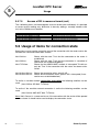
5.5 Usage of items for connection state
Some items can be used to control the state of the connection with the router and on the
novaNet bus connected automation stations:
Net1.OnLine :
Net1.OffLine :
Net1.TLFailure:
Net1.ASxxx.OnLine :
Net1.ASxxx.OffLine :
Shows with the state 'True' that the connection to the router is
established.
Shows with the state 'True' that the connection is cancelled (if
connection was established before)
Shows that the ASNOVANET network is interrupted. This bit can
only be 'True' if the connection with the router has been established.
Shows the connection with a specific AS.
Shows which connection with a specific AS is interrupted (if connection was established before).
To realise a novaNet network connection interruption the following condition can be
used:
(Net1.OffLine OR Net1.TLFailure)
To realise if the novaNet network connection is online the following condition can be
used:
(Net1.OnLine AND NOT Net1.TLFailure)
Note: Net1.Connect is a command to use if the connection with the router will be opened
or closed. It should not be used to display the connection status.
30
7001063003 T3
Sauter Systems
novaNet OPC Server
5
Usage
5.6 Usage of Remote OPC (DCOM)
The OPC server can be used by a remote client only if the computer and the application
are configured with correct DCOM settings. This settings can be done with help of the
Windows application 'dcomcnfg.exe'.
It is not possible to provide a sample configuration because the security requirements
are different for each application. But in all cases it is recommended to follow some basic rules for all computers where the OPC server is running:
Keep all the default COM security settings for the computer (access and launch
permissions). To secure access to the server it can be required to abrogate the
access rights for 'all users'.
Keep all the default DCOM communication properties for the computer (Connect
/ Identify).
For the application DCOM 'SAUTER ASNovanetRemote OPC Server V1.0':
Set up a user account with password (and no administrator account) for the
operation of the server on the register 'Identify'. If the computer is member of
Windows domain the user account has to be of this domain.
Eventually add certain user accounts in the register 'Security' for access and
launch permissions to accomplish the desired requirements and security limits.
Limitation of this version: Because the OPC server communicates with the program
(OCSTrace) to visualise traces using a Windows mechanism it is required that both executed programs are started from the same user. If the OPC server is running through a
user account as described above it cannot communicate with the program to visualise
the traces. This can cause problems during the phase of installation and tuning. In this
case it is recommended to specify the user ID for the OPC server to 'INTERACTIF'. In
this configuration the server cannot run as closed session.
7001063003 T3
Sauter Systems
31
novaNet OPC Server
5
Usage
5.7 Client application : Usage of the time
program control
In the client application, insert an OLE object corresponding to the chosen component:
Sauter.TimeProgram Control
Sauter.TimeProgramFra Control
for the English version
for the French version
The ProgID of the time program is Sauter.TimeProgramCtl.1 and Sauter.TimeProgramCtlFra.1
The control is stand alone and no other parameterisation is needed. Nevertheless, this
component is using the services from the OPC server. Therefore, the OPC server needs
to be installed on the same machine and running in order for the component to work
properly.
Note : also the control is an ActiveX component, it can not be seen in the ActiveX control
list of the system. For example to be able to use it in Visual Basic (version 6), it
has to be selected in the insertable objects and not from the ActiveX list in menu
Project/Component.
32
7001063003 T3
Sauter Systems
novaNet OPC Server
5
Usage
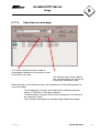
5.7.1Usage of the control
5.7.1.1
1
2
3
First page
Use the dropdown combo box 'AS' to select an automation station to explore.
Check the status line to see the result of the operation, this line will indicate
whether the selected automation station can be explored.
Select the MFA to be programmed using the 'MFA' input box.
Double-click on the line to be edited from the list. With clicking on <new>, a new
time program will be created.
7001063003 T3
Sauter Systems
33
novaNet OPC Server
5
Usage
5.7.1.2
Dialog to edit a time program
This dialog allows you to fully edit a time program.
1
2
3
4
Select the type of time program (period) using the upper buttons. Depending on
this first choice the relevant parameters are shown to the user.
Change the starting time in the 'Time' input box. In 'hourly' mode, the hour field
contains '**' to indicate that the hour parameter is not relevant and cannot be
changed, since it will be started every hour.
Change the starting date. Depending on the type of time program, you will be
able to enter :
- a date using the calendar ('once' and 'yearly' mode)
- a day of the week (in 'daily' and 'weekly' mode)
- a day of the month (in 'monthly' mode)
Click on the 'Edit' button to change the command.
The 'Delete' button is allowing the deletion of the currently selected time program (after
confirmation).
Notes : In field 'Hour', the value '**' means starting every hour.
In the 'Minutes' field the following values have a special meaning:
P4 : means command will be executed every 4 minutes
P8 : means command will be executed 8 times an hour
P15 : means command will be executed every 15 minutes
P30 : means command will be executed every 30 minutes
34
7001063003 T3
Sauter Systems
novaNet OPC Server
5
Usage
In "Weekly" mode, selection of the following days is possible:
- Monday to Sunday (fill or replacement): Activation on the day of the week
indicated, taking into account the possible replacement executed by programming the calendar.
- Special day 1 to Special day 8: Special days defined by the calendar
- Every day except (Monday, Tuesday,…weekend): Activation every day of
the week except the indicated day (or the weekend).
- Monday to Sunday (real): Activation on the real day of the week, independently of replacement days programmed by means of the calendar.
5.7.1.3
1
2
3
Dialog to edit a analogue command
Choose the type of command (Analogue in the screenshot). ATTENTION: Make
sure the type is compatible with the selected MFA !
Depending on the type, the dialog will display the relevant parameters to the
user.
Use buttons in 'Command' box to define the action to be executed:
Select 'Set in HDB' for having the value transferred in the historical database.
Select 'Set Value' for writing a value.
If 'Auto' is checked, the value is set to the automatic modus.
7001063003 T3
Sauter Systems
35
novaNet OPC Server
5
Usage
5.7.1.4
1
2
3
36
Dialog to edit a binary command
Choose the type of command (Command (binary) in the screenshot).
ATTENTION: Make sure the type is compatible with the selected MFA !
Depending on the type, the dialog will display the relevant parameters to theuser.
Use buttons in 'Command' box to define the action to be executed:
Select 'Set in HDB' for having the value transferred in the historical database.
Select 'Set Value' for writing a value.The check boxes 1 to 6 represents reprsent
the 6 output stages for the command. Checking a box will set the corresponding
output stage to 1, where is a not checked it will set the output to 0.
If 'Auto' is checked, the command is set to the automatic modus.
7001063003 T3
Sauter Systems
novaNet OPC Server
5
Usage
5.7.1.5
Operations on main page
This counter indicates the total number of
time programs defined in the automation station
(at the time it was read).
This indicator means some modifications have been done and are not yet
saved to the automation station.
When selecting a new automation station, the component will automatically propose to
save the changes.
-
7001063003 T3
The 'Read' button is forcing a new read from the selected automation
station. ATTENTION : all changes will be lost.
The 'Write' button is forcing a write of the time programs and calendar to
the automation station.
The 'Calendar' button opens the calendar dialog window to be edited
Sauter Systems
37
novaNet OPC Server
5
Usage
5.7.1.6
1
2
3
4
5
6
38
Edit of the calendar
The calendar edit dialog is displaying an annual calendar for two years
To change the replacement day of a given date :
Select the date in the calendar.
Click on button 'Select day'.
A dialog allows you to choose a replacement day on the given date.
The bold displayed days have a changed replacement day.
7001063003 T3
Sauter Systems
novaNet OPC Server
6
Operation of OPC Server
6 Operation of OPC Server
6.1 Read and write
The 'AsyncRead' and 'AsyncWrite' parameters allows to choose an synchronous or
asynchronous execution of the read/write operations. The choice is mainly driven by the
client application.
In order to limit the number of transactions on the communication bus, the OPC server is
grouping the read and write requests, and generates combined transactions. The collecting time is specified in the 'ReadDelay' and 'WriteDelay' parameters, in the configuration file.
Normally, the server is doing a synchronous read transaction on the automation station
on each reading of an item. Nevertheless, because a number of client applications are
doing a periodical polling that could possibly interfere with the internal refreshing process, the 'IgnoreRead' parameter allows (if set to -1) to ignore all reading requests. The
update will happen with spontaneous sending of values to the client application.
The 'ReadMaskDelay' parameter specifies the time during which all values returned by
the refreshing process are ignored after a writing operation, this prevents updating the
client application with inconsistent data. The default value of 3 seconds should apply in
most cases. If a fluctuation is detected on writing processes, this value has possibly to
be increased.
The 'ContractTimeout' parameter specifies the maximum wait time when executing a
request on the bus. It can be increased if related error messages are detected in the
trace window.
The 'HDBContractTimeout' parameter specifies the maximum wait time when executing
a read of the historical database on the bus. It can be increased if related error messages are found in the trace window.
7001063003 T3
Sauter Systems
39
novaNet OPC Server
6
Operation of OPC Server
6.2 Presence test of the automation station
If the revision of the Router/Routel firmware is older as 'F':
The OPC server makes a read of word 'MFA60DW6' for each declared automation station on regular time interval in order to check the communication line status to each
automation station. This polling occurs with a period defined in the 'StatusPolling' parameter in the configuration file. A value of 0 suppresses this polling.
If the revision of the Router/Routel firmware is 'F' or newer:
The OPC server is scanning the router to get the number of automation stations on the
network. As soon as the amount is changed the server requests a spontaneous emission from each single automation station to recognise which automation stations are
online or offline. The wait time for all feedback messages is declared with the parameter
'CheckAliveDelay'. The server presumes having received all feedbacks if the router does
not give new information within a number of successive request cycles defined with a
parameter in the supervisory interrogation.
6.3 Information with spontaneous messages
The OPC server is automatically setting the automation stations to have spontaneous
messages for measurement values, BinaryFeedback and counter values. The parameterisation of the spontaneous subscribed data points is done in the INI file associated to
the network.
The programming of the spontaneous messages depends on the operation mode:
• Router-Mode
The mode of spontaneous message 'online' is programmed during the start of
the connection (Detection of the presence of the automation station). MFAs
which are not for 'online' mode parameterised are programmed with the 'offline'
mode. During disconnection a new re-programming is not required.
• Routel-Mode – outgoing call manually activated (with writing of item
Net1.Connect)
The mode of spontaneous message 'online' is programmed during the start of
the connection (Detection of the presence of the automation station). MFAs
which are not for 'online' mode parameterised are programmed with the 'offline'
mode. MFAs with 'online' mode programmed are re-programmed to 'offline' mode
during disconnection.
• Routel-Modus – incoming call
The mode of spontaneous message 'offline' is programmed during the start of
the connection (Detection of the presence of the automation station). Only MFAs
with 'online' mode programmed are re-programmed. In order to the case that a
outgoing call would be interrupted earlier, it can invalidate this programming
'online'. During disconnection a new re-programming is not required.
40
7001063003 T3
Sauter Systems
novaNet OPC Server
6
Operation of OPC Server
6.4 Information with polling requests
Those information of the automation stations cannot be notified spontaneous are read
by a polling procedure with a rate that is specified in the parameter 'ReadPolling'. A
value of 0 suppresses the polled reads. The polling is only executed in the router mode.
Depending on the client, it can make sense to stop this polling to not overload the communication lines.
7001063003 T3
Sauter Systems
41
novaNet OPC Server
6
42
Operation of OPC Server
7001063003 T3
Sauter Systems
novaNet OPC Server
A1
List of all items of the OPC server
ANNEX
A1 List of all items of the OPC server
Hierarchy
Description
Traces
Defines the trace message level.
Watchdog
Watchdog indicator
WatchdogDate
Watchdog indicator
WatchdogInfo
WatchdogTest
ComLines
Information on the origin of watchdog
activation.
Watchdog test item (allows manual
activation of the WD for test).
Data type R/W Comment
Allows filtering and limitation
of trace massages
Positioned at 1 periodically in
VT_I2
R/W
normal state.
Updated periodically in normal
VT_BSTR R
state.
VT_I1
VT_BSTR
R/W
R "OK" in normal state.
VT_BOOL R/W Item invisible in the browser.
Branch of descriptors for communication lines (remote connection via modem)
.LineXXX
Branch of a line
.Name
Name of the line
VT_BSTR
Defines the logical name of a
line
R Logical name
.State
State of the line (error message)
VT_BSTR
R
.OnLine
Connection indicator
VT_BOOL
R
.PhoneNumber
Phone number
VT_BSTR
.DeviceName
System name of this line (TAPI)
VT_BSTR
R Only for outgoing calls
Name of the 'TAPI' device
R
connected to this line
RouterXXX
Branch of a router
--
.ComPort
Communication port number
VT_I1
.ComSpeed
Communication speed (Baud rate)
VT_I4
.Address
PC-Address
VT_I4
.Connect
.ConnectDate
.OnLine
.OffLine
.NetworkError
.Id
.SetDate
Command for connection / disconnection
Date of the last connection
State: Router connected
Status: Abortion of the connection with
the router
Last error code received from router
Identification string of router
Flag to write current date to all automation stations
Defines the logical name of
the AS network
With W: forces a new initialiR/W
sation of the communication
R
Defined in the configuration
R
file
VT_BOOL R/W
VT_BSTR
R
VT_BOOL
R
VT_BOOL
R
VT_I4
VT_BSTR
R
R
VT_BOOL
W
.NetworkID
ID of ASNOVANET network
.ClientID
ID of the application in the router
VT_BSTR
.Violation
Flag / Indicates a call by a violation
VT_BOOL
R
.PowerReturn
Flag / Indicates a call by power return
Flag / Indicates a call by total failure of
the novaNet bus
Flag / Indicates a call by changes of
number of connected AS
Shows in text format the state of the
connection
Indicates the number of controllers
present on the bus
VT_BOOL
R
VT_BOOL
R
VT_BOOL
R
VT_BSTR
R
VT_I4
L
.TLFailure
.ASmutation
.State
.NumASOnBus
7001063003 T3
VT_UI4
With W: current date is sent to
all automation stations
Network ID (for distinction /
R
incoming calls)
R
Sauter Systems
43
novaNet OPC Server
A1
List of all items of the OPC server
.NumTelegramsToRead
.CheckAlive
VT_I4
L
VT_BOOL
L/E
.ComLine
Branch of descriptors for used communication lines
.Name
Name of the used line
VT_BSTR
.PhoneNumber
Phone number to be dialled
VT_BSTR R/W
.State
State of the line (error message)
VT_BSTR R/W Copy of line state
Indicates if incoming call or outgoing
VT_BOOL R If true, incoming call
call
Counter of incoming calls since start of
VT_I4
R
server
Counter of outgoing calls since start of
VT_I4
R
server
.Incoming
.NumIncomming
.NumOutgoing
-R
Defines the logical name of
the used communication line
.Routel
Branch for input of routel parameters
.PhoneChannel1
Number to be dialled for phase 1
VT_BSTR R/W
.PhoneChannel2
Number to be dialled for phase 2
VT_BSTR R/W
.PhoneChannel3
Number to be dialled for phase 3
VT_BSTR R/W
.ASXXX
Branch of an automation station
.OnLine
State: Automation station connected
VT_BOOL
1: Automation station conR nected, 0: Automation station
not connected
.OffLine
State: Break of connection with automation station
VT_BOOL
R
.Address
Address of automation station
VT_I4
R
--
The parameter for routel
--
Defined in the configuration
file
.PowerFail
Indication for battery power
VT_BOOL
R
.Date
Current date of automation station
Identification string of automation
station
VT_BSTR
R
VT_BSTR
R
VT_BOOL
With W: all items subscribe to
W the automation station are
being read
.Id
.Refresh
Request to read all items
.MFAnnn
Branch of MFA
.DWnnn
Access to a DW in decimal format
.DWHexnnn
Access to a DW in hex format
.DWMeasurennn
Access to a DW as a measurement
.Measure
.SetPoint
.Counter
Read of a measurement
VT_R8
R
Write of a analogue command
VT_R8
R/W
Checking the auto bit for the analogue
VT_BOOL R/W
command
Re-read the actual analogue command
VT_R8
R
Re-read the auto bit of the actual
VT_BOOL R
analogue command
Re-read the local bit of the actual
VT_BOOL R
analogue command
Read of counter
VT_R8
R
.Command
Write binary command
.SetPointAuto
.SetPointFeedback
.SetPointFeedbackAuto
.SetPointFeedbackLocal
.Cmd1
44
Indicates the number of telegrams
waiting to be read in the router.
Allows manual activation of a CheckAlive procedure.
- Word decomposition into bits
-VT_I4
R/W
VT_BSTR R/W
VT_R8
R/W
Ordered: 1, 2, 3, 4, 5, 6, auto,
local
VT_BOOL R/W
Bit I
VT_I1
R/W
.Cmd2
VT_BOOL R/W
Bit II
.Cmd3
VT_BOOL R/W
Bit III
.Cmd4
.Cmd5
VT_BOOL R/W
VT_BOOL R/W
Bit IV
Bit V
7001063003 T3
Sauter Systems
novaNet OPC Server
A1
List of all items of the OPC server
.Cmd6
VT_BOOL R/W
Bit VI
.Auto
VT_BOOL R/W
Bit Auto
.Local
VT_BOOL R/W
VT_BOOL
Bit Local
Ordered: 1, 2, 3, 4, 5, 6, auto,
R
local
R
Bit I
.Cmd2
VT_BOOL
R
Bit II
.Cmd3
VT_BOOL
R
Bit III
.Cmd4
VT_BOOL
R
Bit IV
.Cmd5
VT_BOOL
R
Bit V
.Cmd6
.Auto
VT_BOOL
VT_BOOL
R
R
Bit VI
Bit Auto
Bit Local
.CommandFeedback
.Cmd1
Re-read the binary command
- Word decomposition into bits
.Local
.BinaryFeedback
.Bit24
VT_I1
VT_BOOL
R
Read binary feedback
VT_BOOL
R
- Word decomposition into bits
VT_BOOL
R
.Bit25
VT_BOOL
R
.Bit26
.Bit27
VT_BOOL
VT_BOOL
R
R
.Bit28
VT_BOOL
R
.Bit29
VT_BOOL
R
.Bit30
VT_BOOL
R
.Bit31
VT_BOOL
R
.History
.StartDate
Branch for historical data
Global start date
-VT_BSTR R/W Common date for all MFAs
.EndDate
Global end date
VT_BSTR R/W Common date for all MFAs
.MFAnnn
.StartDate
Branch of a MFA
Local start date of MFA
-VT_BSTR R/W
.EndDate
Local end date of MFA
VT_BSTR R/W
.Read
Read command
VT_BOOL
W
VT_BSTR
R For progress control
Starts the reading of the
specified range of dates
*
.CurrentDate
*
.CurrentCount
Sends back the last read date of the
historical data.
Progress counter, during reads
VT_I4
R For progress control
*
.Status
State of HDB / possible errors
VT_I4
R For progress control
*
.Measure
Read of historical measurement values
VT_R8
R
*
.Counter
Read of historical counter values
VT_R8
R
*
*
.BinaryFeedback
.Bit24
Read of historical binary feedback
- Word decomposition into bits
VT_I1
VT_BOOL
R
R
*
.Bit25
VT_BOOL
R
*
.Bit26
VT_BOOL
R
*
.Bit27
VT_BOOL
R
*
.Bit28
VT_BOOL
R
*
*
.Bit29
.Bit30
VT_BOOL
VT_BOOL
R
R
*
.Bit31
VT_BOOL
* : Items noted with stern asterisk are private: each client receives own values
R
.Diag
Branch for direct access items
--
Items for direct access to
memory in automation station
.ColumnXXX
To read from a DW column
--
For diagnosis or special
functions
.MFA
MFA selection
VT_I2
R/W
.DW
First DW selection
VT_I2
R/W
.Count
Selection for number of DW to read/write
VT_I2
R/W
7001063003 T3
Sauter Systems
45
novaNet OPC Server
A1
List of all items of the OPC server
.Read
Command to read
VT_BOOL W
VT_ARRAY
R/W
| VT_UI4
.Data
Results
.LineXXX
To read from a DW line
.MFA
First MFA selection
VT_I2
R/W
.DW
DW selection
VT_I2
R/W
.Count
Selection for number of MFAs to read/write
VT_I2
R/W
.Read
Command to read
.Data
Results
.DWDecimalXXX
To read a DW in decimal format
.MFA
.DW
MFA selection
DW selection
.Read
Command to read
VT_BOOL
W
.Data
Result
VT_I4
R/W
.DWHexXXX
.MFA
To read a DW in hex format
MFA selection
-VT_I2
R/W
.DW
DW selection
VT_I2
R/W
.Read
Command to read
VT_BOOL
W
.Data
Result
VT_BSTR R/W
.DWMeasureXXX
To read a DW as measurement
.MFA
MFA selection
VT_I2
R/W
.DW
DW selection
VT_I2
R/W
.Read
Command to read
.Data
Result
--
VT_BOOL W
VT_ARRAY
R/W
| VT_UI4
-VT_I2
VT_I2
R/W
R/W
--
VT_BOOL
W
VT_R8
R/W
NOTE:
The bolded IDs represents a start of a new branch (of the tree)
Data type definition:
VT_DATE
Date in OLE format
VT_BSTR
Character string (variable size)
VT_UI1
Unsigned byte
VT_I1
Signed byte
VT_I2
Signed word with 2 bytes
VT_I4
Signed word with 4 bytes
VT_R4
Real with 4 bytes (float)
VT_BOOL
Boolean with 1 byte (true/false)
VT_ARRAY… Array of …
EXAMPLES:
Writing "2" in item "Admin.Port" will result in re-initialization of the communication using COM2 (if previously it was COM1)
Read of item "Router1.Speed" : 19200 returns current speed in bauds.
The item "Router1.AS00012.OnLine" indicates the connection status of automation station 'AS00012' on router 'Router1'.
The item "Router1.AS00012.MFA3.DW6" is addressing (only in read only mode) the DW 6 on MFA 3 of the 'AS00012
automation station.
The item "Router1.AS00012.MFA3.Counter" is reading counter declared in MFA 3 of automation station AS00012.
46
7001063003 T3
Sauter Systems
novaNet OPC Server
A2
History of changes
A2 History of changes
Version 2.1.0.0 to 2.2.0.4
Correction
Evolution Description
x
x
x
x
x
x
x
x
x
x
x
x
x
x
x
x
x
x
Added item [Router].ConnectDate that shows date of last connection.
Added item [Router].OffLine. This item changes to 'True', if attempted connection is
not established. It could be useful to activate an alarm to show the non presence of a
router. The item is set to 'False' if the next connection with the router is successful.
Added item [Router].[ASxxx].OffLine. This item changes to 'True', if the automation
station is not 'online' while the router is being connected. It is useful to activate an
alarm to show the non presence of an automation station. The item set to 'False' if
the next connection with the automation station is successful.
The items TLFailure, ASMutation, PowerReturn und Violation keep operative after a
disconnection. Thus, visual traces of these alarms stay in operation.
The item TLFailure is set to 'True' in router mode if the novaNet bus is disconnected.
The connection with a call of the routel is being established again normally after a
failure (disconnection) of the novaNet bus.
Oppression of a inadequate disconnection after a minute.
Retry of last sent frame after a receiving error.
Identification of calling island with help of the ID string available from the routel and
not anymore with the numerical ID. The ID string has to be subscribed in the initialisation file with the variable NetworkID (was used to contain the numerical ID).
Correction of occurred error with retrieval of historical data.
Correction of not happened actualisation of entries when just the spontaneous message of a measurement is executed.
Oppression of writes for DW0 on page 1 of the routel.
Actualisation of IDs of EPROMS EYR203 and EYL106.
Support for revision F of EYZ291 EPROM.
Dating the OPC server to UTC time.
The exception date 01/01/1996 is now coded on UTC.
Return to the identified and corrected date fort he HDB messages.
Change in the management of the feedback messages.
Version 2.2.0.4 to 2.2.0.5
Correction
Evolution Description
X
Correction in the operation of the item TLFailure to take account of the connection
mode of the router or routel.
Version 2.2.0.5 to 2.2.0.6
Correction
Evolution Description
X
X
X
X
x
x
7001063003 T3
Managing the routine checkalive – Recognition of presence of automation stations
with EPROM router F or later – the old recognition method (polling date) is still active
if the EPROM is older than revision F. The CheckAlive request is repeated if not all
automation stations reply (only in router mode. No retries in routel mode).
Changes in the connection sequence to allow two programming modes for spontaneous messages: online (during the connection), offline (with disconnected connection) to allow spontaneous messages with a network connection. The offline mode is
programmed during disconnection (with outgoing call) and during connection (with
incoming call and only if online mode is configured for the MFA).
The parameter AutoConnectOnStart allows with the start in routel mode to suppress
the automatic connection establishment.
Specifying specific PC address for each network.
Change in the connection routine: better synchronisation with the connection state in
routel mode.
Displays the steps of connection state with item [Router].State.
Sauter Systems
47
novaNet OPC Server
A2
History of changes
Connection: Connecting..., On Refresh..., Connected
Disconnection: Parameter Setting..., Disconnected
x
x
x
x
x
x
x
x
x
x
x
x
x
x
x
x
x
x
x
x
x
The time for the step 'On Refresh' depends on the number of values to be read.
Oppression to save temporary connection errors those would produce a wrong disconnection of the connection with the automation stations.
Parameterisation of wait time in the polling loop for the router. Default value = 15 ms.
Added parameter: RouterPolling Delay.
Oppression of error message: R291: Response: F7 frame too short. This message
was shown with a temporary error on the novaNet bus; the router sends therefore
empty data frames (they are displayed correctly though; these frames have not
special importance and can be ignored). A debugging trace is now showing this
case.
Management of retrieving the changed historical data.
This is done in a separate thread that takes the process till the data is transferred to
the clients.
It allows the subscription of multiple clients to the same item and if required it manages the frequency for each different client. During the retrieval of the data is a reread not possible.
Supervision of the start and end date.
Added state item to control the progress.
Oppression of the message from values, that are older than the start date (the protocol transfers in blocks of 16 values)
The value items and CurrentCount and CurrentDate are exceptions from now on (an
item has for each client its own value)
Addition of parameters HDBRetrieveTimeout to specify the maximal time to send
back the historical data to the clients. The retrieval process is interrupted if not all
clients will have retrieved all values.
Item [Router].[Line].State: Addition of an information for a failure of the connection.
Addition of the parameter SetRoutelNotification that allows invalidating the programming of spontaneous messages with incoming calls in routel mode to optimise the
connection time.
Changes in the connection sequence to allow two programming modes for spontaneous messages: online (during the connection), offline (with disconnected connection). The offline mode is programmed during disconnection.
The parameter AutoConnectOnStart allows with the start in routel mode to suppress
the automatic connection establishment.
Specifying specific PC address for each network.
Change in the connection routine: better synchronisation with the connection state in
routel mode.
Correction of initial value for the dates in the history branch. The default date
(01/01/1996) is set to the current date when the item is subscribed. These items
have now the property BAD and with not read historical data they are 01/01/1996.
Added a trace message (warning) if receiving an alarm bit in the historical database
of MFA60.
Added traces messages (debugging) to show the programming of the spontaneous
messages for each MFA
Managing autoconnection with a write of item [Router].[AS].Refresh.
Timeout management of changed connection. The timeouts are 2 seconds in router
mode (fixed setting) and in routel mode adjustable but with a default value of 5 seconds.
Added a server parameter RoutelCommTimeout to control the timeout of the connection in routel mode.
The items NetworkID and NetworkError can now only be read.
Actualisation of user manual (Version 2.2.0.6).
Changes in the management of item properties:
In router mode and KeepValid parameter = 0:
Router/AS not connected: BAD: NotConnected
Router/AS connected: GOOD: NonSpecific
Router/AS not connected: BAD: LastKnown
In router mode and KeepValid parameter = 1:
Router/AS not connected: BAD: NotConnected
Router/AS connected: GOOD: NonSpecific
Router/AS not connected: GOOD: NotConnected
48
7001063003 T3
Sauter Systems
novaNet OPC Server
A2
History of changes
In routel mode:
Routel not connected: BAD: NotConnected
Routel connected: GOOD: NonSpecific
…
AS OffLine detected: BAD: LastKnown
Routel not connected: BAD: LastKnown
…
AS Online detected: GOOD: NonSpecific
Routel not connected: GOOD: NotConnected
In this case the property GOOD can be retained after disconnection (if the AS during
disconnection was online)
x
x
x
x
x
x
x
x
x
x
x
7001063003 T3
The items in the history branch are not involved of a disconnection. The service
items (OnLine, Connect..) stay always valid.
Change in the meaning of offline items; those items indicate a default condition fort
he connection:
[Router].OffLine changes to 1 if the attempt for a connection with the router/routel
fails.
[Router].[Net].OffLine changes to 1 if the automation station does not respond on a
request.
The state Connected / Not Connected is always shown with the online items.
Oppression of reads from MFA60DW2 during the connection establishment. The
item [Router].[AS].PowerFail is set default to 0. It is actualised with a spontaneous
message from value.
The management of the spontaneous message for the item CommandFeedback was
not supported but is now added.
In routel mode (incoming and outgoing) the bits 10, 14, and 17 of DW2 are not set to
1 anymore on the 1st routel page. The current value in the routel is kept.
Added the parameter IdleDetectionCount to specify the criteria to acquire the inactivity on the bus: Number of consecutive reads of router reading pointers without successful transmitted values (immobile pointer). This parameter is used to get the end
of the checkalive process.
Changes in the management of the communication error handling: Each transaction
(request of router) can be repeated maximal 10 times upon an error within 30 seconds. If no responses is received within this conditions after this time the connection
will be disconnected (without writing the pointer in routel mode). In routel mode the
scheduled writes will be cancelled (and therefore will be lost) to avoid a collision of
the PC and routel with an immediate and simultaneous repetition..
In routel mode and with the automatic outgoing call the spontaneous messages are
not programmed to 'online' and 'offline' mode to limit the connection time and to avoid
the actualisation of the values which is not requested with an automatic connection
(Writing of commands, reading of HDB, reading/writing of time programs)
Correction in the management routine for requests: The termination of the timeout for
the request lead in some cases to a deadlock that disconnected the communication
and avoided the termination of the server.
Changes in the synchronisation of the connection establishment in routel mode: It is
assumed that all telegrams are transmitted to the routel before the reading and
writing requests are started. Therefore it is prevented that the transmission of the first
requests is cancelled by the timeout, if the information volume is too big (i.e. retransmission of HDB values caused by a connection error).
Changes in the code interpretation of spontaneous messages in router mode to be
consistent with the routel mode: The code of a spontaneous message can be shown
in online mode (10 to 70) as well in offline mode (0 to 7 as before). The online mode
has priority if it is not 0. Thus the compatibility with earlier versions is assured.
Correction in the interpretation of MULTIRANDOM frames: A check of the generic
receiver address occurs with the first value of the frame. If the first value was not
meant to be for the PC the whole frame had been rejected.
Sauter Systems
49
novaNet OPC Server
A2
History of changes
Version 2.2.0.6 to 2.2.0.7
3.2.2005
Correction
Evolution Description
x
x
x
x
Component for the time program: Change in the UI for the daily time program in the
format 'daily except…'. These time programs are now available in weekly formats.
Component for the time program: Added the codes of an exception day for the real
days in the weekly format.
Component for the time program: Different changes in the coding of the data words
corresponding to the commands.
Consideration of the 4 possible routel recipients with the programming of the spontaneous messages and the CheckAlive request. The bits 16 and 17 of the DW32 are
set for each island registered PC address regarding to the INI file.
Version 2.2.0.7 to 2.2.0.8
Correction
Evolution Description
x
x
x
x
x
x
x
x
x
x
Adds an option that inhibits automatic connection per island at start-up, in routel as
well as in router.
Parameter INI: AutoConnectOnStart (for each island).
Integration of TAPI diagnostic routines. "A log file of traces relating to TAPI activities".
Generation of the file can be deactivated:
Parameter INI: LogTAPIEvents (Server section)
Addition of a modem monitoring task. If a free modem is not available, then closing and
reopening of the line is forced. The frequency is configurable:
Parameter INI: ChekTAPIPeriod (Server section)
Indicates the polling period in milliseconds (0 to deactivate, 180000 default)
Addition of a line cut-off function on incoming calls if no routel has been detected after
30 seconds. The line is interrupted and returned to the pool.
Following an out-going connection failure, the line is closed, reopened and then returned to the pool
Addition of a watchdog which monitors the activity of internal polling tasks of the server
(3 tasks per island plus the TAPI management task).
Creation of 3 items:- Watchdog: Used for implementing the full watchdog in E².
- WatchdogDate: Displays the server date in text, updated periodically by period of the
watchdog.
- WatchdogInfo: Displays a text identifying the task at the origin of activation of the
watchdog.
Parameter INI: WatchdogPeriod (Server section). Watchdog period in milliseconds
(10000 default, 2000 minimum value).
Modification of the CheckAlive detection. Addition of a masking delay before taking into
account "UGL number changed" data originating from the router. This avoids launching
CheckAlive repetition when the bus is loaded and the router returns an account error.
Parameter INI: CheckAliveMaskDelay (per island).
In milliseconds (default value 15000).
The CheckAlive is not launched if data for a change in the number of controllers is
received during a disconnection.
Modification of "Connected" status detection. During connection, the State item moves
to the ‘Connected’ state when the queue file for router values is emptied AND the
‘NetworkIdle’ condition has been detected.
Modification of the subscription sequence of items: Request for asynchronous reading
(instead of synchronous) and improved management of internal lock-in during subscription to optimise subscription.
Addition of parameters to specify the size of internal queue files:
Parameter INI: WriteQueueSize (Server section) default = 16000
Parameter INI: ReadQueueSize (Server section) default = 4000
x
50
7001063003 T3
The write queue file is common to all the ASs in the island, the read queue file concerns only one AS.
Addition of NumASOnBus item (router branch) which indicates the number of ASs
Sauter Systems
novaNet OPC Server
A2
History of changes
x
x
x
x
x
detected by the router.
Addition of NumTelegramsToRead item (router branch) which indicates the number of
telegrams in the router queue file.
Addition of CheckAlive item allowing manually activating a CheckAlive procedure.
Improvement of the trace messages:
- IOPCServerDisp::get_Count traces deleted.
- IOPCItemMgtDisp.get_Count traces of group deleted.
- The name of the island to R291 et ASNOVANET traces added.
Time programmes component: Addition of codes for the day of replacement of real
days in the weekly model.
Time programmes component: Various corrections for coding data words as a function
of the commands.
Version 2.2.0.8 to 2.2.0.9
Correction
Evolution Description
x
Modification of operation mode of the masking delay before taking into account 'AS
number changed’ data originating from the router:1) Reading of this counter by the driver in the router is executed in steps of 15 seconds
instead of 10 seconds.
2) This reading will be validated by the programme only if, during a period T (defined
by parameter CheckAliveMaskDelay), all the acquired values are identical. If a value
validated at the end of a period T is different to the validated value of the preceding
period, then there will be a reaction from the driver which will launch the procedure for
recognition of ASs present.
3) If during the period of validation T, one or several acquired values are not identical,
the number of ASs present will not be validated by the programme, which will not
activate any reaction at the end of this period. At the end of the period of timer T, a
new period of validation commences.
4) If the value defined in timer T (parameter CheckAliveMaskDelay) is set to 0, each
value read by the driver in the router will be validated and can therefore possibly activate a reaction from the programme.
5) With this modification, detection of a new state of AS absence or presence will
therefore be delayed by the value of timer T.
x
x
Modification of the activation time of daily time correction in all the controllers: 12:00
instead of 00:00.
Takes into account the 4 possible destination routels when programming spontaneous
feedback and CheckAlive requests. Bits 16 and 17 of word DW34 are positioned as a
function of the PC address declared in the ini file for each island
Version 2.2.0.9 to 2.2.0.10
Correction
Evolution Description
x
Increased buffer size in the INI file for the lecuture of the list of up to 2000 automation
stations (each station can have an identification name of up to 32 characters).
The buffer can have a total of 66560 characters.
Version 2.2.0.10 to 2.2.0.11
17.2.2006
Correction
Evolution Description
x
7001063003 T3
Change in the consideration of the counter for the available automation stations:
Sauter Systems
51
novaNet OPC Server
A2
History of changes
The reads for the available AS counters (Page1/DW57/bits16-31) is considered only if
the UKB (“CircleControlBit”) cycle-counter (Page1/DW7/bits12-13) has the value 3.
After a cold start the checkalive procedure is started only if the router has finished
three complete request cycles.
x
The change of the value of the UKB cycle-counter is shown in the progress window
over the message ‘UKB cycle counter = x’.
Logging of the data traffic and saving into text files.
For each connection the data traffic is being saved into time limited files. The maximum
amount of data is being able to be parameterised. If the amount is reached the oldest
file is deleted before a new one is being created.
Parameterisation in the section [Server]
NovaNetLogFiles = N,1,1 : On / Off and parameterisation of the recording of the data
traffic.
NovaNetLogFilesDirectory = (empty) : Saving path for the files.
NovaNetLogFilesTest = 0 : On / Off switch in the test mode of the recording of the data
traffic (reserved only for test and quality assurance).
52
7001063003 T3
Sauter Systems
novaNet OPC Server
A3
Operation sequence
A3 Operation sequence
A3.1
Direct Connection: ROUTER mode
A3.1.1
Start of server
With the start of the server the connection request is activated (Connect = -1).
The connection is started automatically.
A3.1.2
Connection establishment
A3.1.2.1
Sequence of the connection in router mode
Step
Description
Router state
1
Manual activation of the connection with writing -1 to the item
[Router].Connect.
OnLine = 0
OffLine =0
2
3
Opening of communication port
Reading router information (page 0) and synchronisation of pointer
« Disconnected »
« Connecting… »
OnLine = -1
OffLine =0
4
5
Writing PC address to the router
Launch of 'CheckAlive' process: Sending the command to acquire
the automation stations online on the bus.
Calculating the refresh time depending on the numbers on the bus
connected automation stations and the number of values to be
actualised for each automation station
actualisation timer
Timeout for the actualisation timer
6
7
« On Refresh… »
« Connected »
3.1.2.1.1 On registration of the presence of an automation station
An automation station is being registered to be online if the server is receiving a value
from the automation station. In general the first received value is a feedback on the
'checkalive' request.
Step
1
2
Description
State of the AS
No value received by automation station
OnLine = 0
OffLine =0
OnLine = -1
OffLine =0
A value received by the automation station
3
Usually program spontaneous messages for this automation
station in 'Online' mode; if no values in 'Online' mode, program
'Offline' mode.
4
Reading of values that are registered items, which are not just
notified caused by spontaneous actualisation.
7001063003 T3
Sauter Systems
53
novaNet OPC Server
A3
Operation sequence
3.1.2.1.2 On registration of a non-presence of an automation station
An automation station is being registered to be offline if it has not responded on a
'CheckAlive' request or the writing request was failing.
Step
1
A3.1.3
Step
Description
State of the AS
No response on the 'CheckAlive' request or a failed write
request
OnLine = 0
OffLine =-1
Disconnection
Description
Router state
1
Manual termination of the connection with writing 0 to the
item [Router].Connect.
OnLine = -1
OffLine =0
2
3
4
Actualisation of status in all automation stations (OnLine = 0)
Terminates all running requests
Closes the communication port
« Connected »
« Disconnecting… »
OnLine = 0
OffLine =0
« Disconnected »
A3.1.4
Connection error
The registration of a connection error is retrying the running transaction up to 10 times
or for a maximum time of 30 seconds.
If no response is received the sequence to terminate the connection is executed and
after 5 seconds the sequence for a new reconnection will be started. As long the item
Connect is -1 the re-connection will by tried continuously.
Step
1
Description
Not recovering connection error
Router state
OnLine = 0
OffLine =-1
« Disconnected »
54
7001063003 T3
Sauter Systems
novaNet OPC Server
A3
Operation sequence
A3.2
Remote operation: ROUTEL mode
A3.2.1
Start of server
With the start of the server the connection is started only if the parameter 'AutoconnectOnStart' is 1.
A3.2.2
Outgoing call to the island manually activated
A3.2.2.1
Sequence of the connection with the routel
Step
Description
Router state
1
Manual activation of the connection with writing -1 to the item
[Router].Connect.
OnLine = 0
OffLine =0
2
Looking for a free communication port from the ports defined in the
INI file. Opening the communication port and reservation of the
modem. If the modem or the line is not available this step is repeated for ever.
Numbering. If the remote routel is not available (no response or
occupied line) the retry of the call will be done as often it is specified with the parameter 'NumRetries' and with a wait delay between 2 retries as defined in the parameter 'RetryDelay'. If the
connection cannot be established after those retries the request for
the connection is stopped (Connect = 0)
Connected line with the modem of the remote routel
Reading the routel information (page 0 and 1) and synchronisation
of the pointer. Deleting the bits 11, 15, 19, 23, 31 of word 7 on
page 1 of routel.
Writing the PC address to the routel
Starting the 'CheckAlive' process: Sending the command to acquire the present automation stations on the bus.
Calculating the refresh time depending on the numbers on the bus
connected automation stations and the number of values to be
actualised for each automation station
actualisation timer
Timeout for the actualisation timer
3
4
5
6
7
8
9
« Disconnected »
« Connecting… »
OnLine = -1
OffLine =0
« On Refresh… »
« Connected »
A3.2.2.1.1
On registration of the presence of an automation station
An automation station is being registered to be online if the server is receiving a value
from the automation station. In general the first received value is a feedback on the
'checkalive' request.
Step
1
2
Description
State of the AS
No value received by automation station
OnLine = 0
OffLine =0
OnLine = -1
OffLine =0
A value received by the automation station
3
Usually program spontaneous messages for this automation station in 'Online' mode; if no values in 'Online' mode, program 'Offline' mode.
4
Reading of values that are registered items, which are not just
notified caused by spontaneous actualisation.
7001063003 T3
Sauter Systems
55
novaNet OPC Server
A3
Operation sequence
A3.2.2.1.2
On registration of a non-presence of an automation station
An automation station is being registered to be offline if it has not responded on a
'CheckAlive' request or the writing request was failing.
Step
1
A3.2.2.2
Step
1
2
3
4
5
6
Description
State of the AS
No response on the 'CheckAlive' request or a failed write request
OnLine = 0
OffLine =-1
Disconnection
Description
Router state
Manual termination of the connection with writing 0 to the
item [Router].Connect or timeout by the parameter 'ManualInactivityTime' defined connection timer, if the net transmits
no values.
OnLine = -1
OffLine =0
Programming of the spontaneous message for all online
automation stations which are configured in 'Offline' mode if
they were programmed to 'online' at connection.
Actualisation of status in all automation stations (OnLine = 0)
Terminates all running requests
Writing of routel pointer (Note. This writing process occurs
during the whole connection time periodically)
Hang up of line and closing the communication port. If the
line in automatic response mode (parameter in ini file) this
port will be open suddenly to reserve the modem.
«Disconnecting … parameter
setting…»
« Connected »
OnLine = 0
OffLine =0
« Disconnected »
A3.2.2.3
Connection error
The registration of a connection error is retrying the running transaction up to 10 times
or for a maximum time of 30 seconds.
If no response is received the line will be dropped and all waiting requests are cancelled.
The connection command is cancelled to avoid a call collision if the routel would call
again.
Step
1
Description
Not recovering connection error
Router state
OnLine = 0
OffLine =-1
« Disconnected »
56
7001063003 T3
Sauter Systems
novaNet OPC Server
A3
Operation sequence
A3.2.3
Outgoing call to the island automatically
activated
A3.2.3.1
Sequence of the connection with the routel
Step
Description
Router state
1
Automatic activation of the connection with writing or reading of an item related to an address in the automation station
OnLine = 0
OffLine =0
2
Looking for a free communication port from the ports defined in
the INI file. Opening the communication port and reservation of
the modem. If the modem or the line is not available this step
is repeated for ever.
Numbering. If the remote routel is not available (no response
or occupied line) the retry of the call will be done as often it is
specified with the parameter 'NumRetries' and with a wait
delay between 2 retries as defined in the parameter 'RetryDelay'. If the connection cannot be established after those retries
the request for the connection is stopped
Connected line with the modem of the remote routel
Reading the routel information (page 0 and 1) and synchronisation of the pointer. Deleting the bits 11, 15, 19, 23, 31 of
word 7 on page 1 of routel.
Writing the PC address to the routel
Setting the actualisation timer to 1 second.
Timeout for the actualisation timer
3
4
5
6
7
8
« Disconnected »
« Connecting… »
OnLine = -1
OffLine =0
« On Refresh… »
« Connected »
A3.2.3.1.1
On registration of the presence of an automation station
An automation station is being registered to be online if the server is receiving a value
from the automation station. In general the first received value is a feedback on the
'checkalive' request.
Step
1
2
Description
State of the AS
No value received by automation station
OnLine = 0
OffLine =0
OnLine = -1
OffLine =0
A value received by the automation station
A3.2.3.1.2
On registration of a non-presence of an automation station
An automation station is being registered to be offline if it has not responded on a
'CheckAlive' request or the writing request was failing.
Step
1
7001063003 T3
Description
State of the AS
A failed write request
OnLine = 0
OffLine =-1
Sauter Systems
57
novaNet OPC Server
A3
Operation sequence
A3.2.3.2
Step
Disconnection
Description
Router state
1
Timeout of connection timer defined by the parameter
'InactivityTime', if the net does not transmit values.
OnLine = -1
OffLine =0
2
Actualisation of status in all automation stations (OnLine
= 0)
Terminates all running requests
Writing of routel pointer (Note. This writing process
occurs during the whole connection time periodically)
Hang up of line and closing the communication port. If
the line is in automatic response mode (parameter in ini
file) this port will be open suddenly to reserve the modem.
« Connected »
3
4
5
A3.2.3.3
OnLine = 0
OffLine =0
« Disconnected »
Connection error
The registration of a connection error is retrying the running transaction up to 10 times
or for a maximum time of 30 seconds.
If no response is received the line will be dropped and all waiting requests are cancelled.
The connection command is cancelled to avoid a call collision if the routel would call
again.
Step
1
Description
Not recovering connection error
Router state
OnLine = 0
OffLine =-1
« Disconnected »
A3.2.4
Incoming call from the island
A3.2.4.1
Sequence of the connection with the routel
Step
1
Description
Registration of a incoming call on a monitored line.
Router state
OnLine = 0
OffLine =0
« Disconnected »
2
3
4
5
6
7
58
7001063003 T3
Connected line with the modem of the remote routel
Reading the routel information (page 0 and 1) and synchronisation of the pointer. Deleting the bits 11, 15, 19, 23, 31 of
word 7 on page 1 of routel.
Writing the PC address to the routel
Starting the 'CheckAlive' process: Sending the command to
acquire the present automation stations on the bus.
Setting the actualisation timer to 1 second.
Timeout for the actualisation timer
OnLine = -1
OffLine =0
« On Refresh… »
« Connected »
Sauter Systems
novaNet OPC Server
A3
Operation sequence
A3.2.4.1.1
On registration of the presence of an automation station
An automation station is being registered to be online if the server is receiving a value
from the automation station. In general the first received value is a feedback on the
'checkalive' request.
Step
1
2
3
Description
State of the AS
No value received by automation station
OnLine = 0
OffLine =0
OnLine = -1
OffLine =0
A value received by the automation station
Programming of the spontaneous messages of the automation
station in offline mode for each data point that is programmed
in online mode. The goal is to delete all online programming
those would exist further after an unexpected disconnection.
A3.2.4.1.2
On registration of a non-presence of an automation station
An automation station is being registered to be offline if it has not responded on a
'CheckAlive' request or the writing request was failing.
Step
1
A3.2.4.2
Step
Description
State of the AS
No response on the 'CheckAlive' request or a failed write
request
OnLine = 0
OffLine =-1
Disconnection
Description
Router state
1
Timeout of connection timer defined by the parameter
'InactivityTime', if the net does not transmit values.
OnLine = -1
OffLine =0
2
3
4
Actualisation of status in all automation stations (OnLine = 0)
Terminates all running requests
Writing of routel pointer (Note. This writing process occurs
during the whole connection time periodically)
Hang up of line and closing the communication port. If the line
is in automatic response mode (parameter in ini file) this port
will be open suddenly to reserve the modem.
« Connected »
5
OnLine = 0
OffLine =0
« Disconnected »
A3.2.4.3
Connection error
The registration of a connection error is retrying the running transaction up to 10 times
or for a maximum time of 30 seconds.
If no response is received the line will be dropped and all waiting requests are cancelled.
The connection command is cancelled to avoid a call collision if the routel would call
again.
Step
1
Description
Not recovering connection error
Router state
OnLine = 0
OffLine =-1
« Disconnected »
7001063003 T3
Sauter Systems
59
novaNet OPC Server
A3
60
Operation sequence
7001063003 T3
Sauter Systems
novaNet OPC Server
A4
Registry of the OPC server
A4 Registry of the OPC server
REGEDIT4
[HKEY_CLASSES_ROOT]
[HKEY_CLASSES_ROOT\CLSID]
[HKEY_CLASSES_ROOT\CLSID\{70DE4D81-DE9C-49b2-990C-D2BD9144F881}]
@="SAUTER ASNovaNetRemote OPC Server V1.0"
"AppID"="{70DE4D81-DE9C-49b2-990C-D2BD9144F881}"
[HKEY_CLASSES_ROOT\CLSID\{70DE4D81-DE9C-49b2-990C-D2BD9144F881}\LocalServer32]
@="C:\\Program Files\\Sauter\\EY3600\\novaNet OPC Server\\OPCASNovaNetRemoteTrace.exe"
[HKEY_CLASSES_ROOT\CLSID\{70DE4D81-DE9C-49b2-990C-D2BD9144F881}\ProgID]
@="SAUTER.ASNovaNetRemote.1"
[HKEY_CLASSES_ROOT\CLSID\{70DE4D81-DE9C-49b2-990C-D2BD9144F881}\VersionIndependentProgID]
@="SAUTER.ASNovaNetRemote"
[HKEY_CLASSES_ROOT\CLSID\{70DE4D81-DE9C-49b2-990C-D2BD9144F881}\Implemented Categories]
[HKEY_CLASSES_ROOT\CLSID\{70DE4D81-DE9C-49b2-990C-D2BD9144F881}\Implemented Categories\{63D5F430CFE4-11D1-B2C8-0060083BA1FB}]
[HKEY_CLASSES_ROOT\CLSID\{70DE4D81-DE9C-49b2-990C-D2BD9144F881}\Implemented Categories\{63D5F432CFE4-11D1-B2C8-0060083BA1FB}]
[HKEY_CLASSES_ROOT\CLSID\{70DE4D81-DE9C-49b2-990C-D2BD9144F881}\Programmable]
[HKEY_CLASSES_ROOT\SAUTER.ASNovaNetRemote]
@="Sauter novaNet OPC Server EY3600 Release 2.2.0.9"
[HKEY_CLASSES_ROOT\SAUTER.ASNovaNetRemote\CurVer]
@="SAUTER.ASNovaNetRemote.1"
[HKEY_CLASSES_ROOT\SAUTER.ASNovaNetRemote.1]
@="Sauter novaNet OPC Server EY3600 Release 2.2.0.9"
[HKEY_CLASSES_ROOT\SAUTER.ASNovaNetRemote.1\CLSID]
@="{70DE4D81-DE9C-49b2-990C-D2BD9144F881}"
[HKEY_CLASSES_ROOT\SAUTER.ASNovaNetRemote.1\OPC]
[HKEY_CLASSES_ROOT\SAUTER.ASNovaNetRemote.1\OPC\Vendor]
@="Sauter"
[HKEY_CLASSES_ROOT\TypeLib]
[HKEY_CLASSES_ROOT\TypeLib\{5F66E430-FC32-11D0-A25F-0000E81E9085}]
[HKEY_CLASSES_ROOT\TypeLib\{5F66E430-FC32-11D0-A25F-0000E81E9085}\1.0]
@="OCSTK 1.0 Type Library"
[HKEY_CLASSES_ROOT\TypeLib\{5F66E430-FC32-11D0-A25F-0000E81E9085}\1.0\0]
[HKEY_CLASSES_ROOT\TypeLib\{5F66E430-FC32-11D0-A25F-0000E81E9085}\1.0\0\win32]
@="C:\\Program Files\\Sauter\\EY3600\\novaNet OPC Server\\OPCASNovaNetRemoteTrace.exe"
[HKEY_CLASSES_ROOT\TypeLib\{5F66E430-FC32-11D0-A25F-0000E81E9085}\1.0\FLAGS]
@="0"
[HKEY_CLASSES_ROOT\TypeLib\{5F66E430-FC32-11D0-A25F-0000E81E9085}\1.0\HELPDIR]
@="C:\\Program Files\\Sauter\\EY3600\\novaNet OPC Server\\"
7001063003 T3
Sauter Systems
61
novaNet OPC Server
A4
Registry of the OPC server
[HKEY_CLASSES_ROOT\AppID]
[HKEY_CLASSES_ROOT\AppID\{70DE4D81-DE9C-49b2-990C-D2BD9144F881}]
@="SAUTER ASNovaNetRemote OPC Server V1.0"
"RunAs"="Interactive User"
"AuthenticationLevel"="1"
[HKEY_CURRENT_USER]
[HKEY_LOCAL_MACHINE]
[HKEY_LOCAL_MACHINE\SOFTWARE]
[HKEY_LOCAL_MACHINE\SOFTWARE\Classes]
[HKEY_LOCAL_MACHINE\SOFTWARE\Classes\AppID]
[HKEY_LOCAL_MACHINE\SOFTWARE\Classes\AppID\{70DE4D81-DE9C-49b2-990C-D2BD9144F881}]
@="SAUTER ASNovaNetRemote OPC Server V1.0"
[HKEY_LOCAL_MACHINE\SOFTWARE\Classes\CLSID]
[HKEY_LOCAL_MACHINE\SOFTWARE\Classes\CLSID\{70DE4D81-DE9C-49b2-990C-D2BD9144F881}]
@="SAUTER ASNovaNetRemote OPC Server V1.0"
"AppID"="{70DE4D81-DE9C-49b2-990C-D2BD9144F881}"
[HKEY_LOCAL_MACHINE\SOFTWARE\Classes\CLSID\{70DE4D81-DE9C-49b2-990C-D2BD9144F881}\LocalServer32]
@="C:\\Program Files\\Sauter\\EY3600\\novaNet OPC Server\\OPCASNovaNetRemoteTrace.exe"
[HKEY_LOCAL_MACHINE\SOFTWARE\Classes\CLSID\{70DE4D81-DE9C-49b2-990C-D2BD9144F881}\ProgID]
@="SAUTER.ASNovaNetRemote.1"
[HKEY_LOCAL_MACHINE\SOFTWARE\Classes\CLSID\{70DE4D81-DE9C-49b2-990CD2BD9144F881}\VersionIndependentProgID]
@="SAUTER.ASNovaNetRemote"
[HKEY_LOCAL_MACHINE\SOFTWARE\Classes\CLSID\{70DE4D81-DE9C-49b2-990C-D2BD9144F881}\Implemented
Categories]
[HKEY_LOCAL_MACHINE\SOFTWARE\Classes\CLSID\{70DE4D81-DE9C-49b2-990C-D2BD9144F881}\Implemented
Categories\{63D5F430-CFE4-11D1-B2C8-0060083BA1FB}]
[HKEY_LOCAL_MACHINE\SOFTWARE\Classes\CLSID\{70DE4D81-DE9C-49b2-990C-D2BD9144F881}\Implemented
Categories\{63D5F432-CFE4-11D1-B2C8-0060083BA1FB}]
[HKEY_LOCAL_MACHINE\SOFTWARE\Classes\CLSID\{70DE4D81-DE9C-49b2-990C-D2BD9144F881}\Programmable]
[HKEY_LOCAL_MACHINE\SOFTWARE\Classes\SAUTER.ASNovaNetRemote]
@="Sauter novaNet OPC Server EY3600 Release 2.2.0.9"
[HKEY_LOCAL_MACHINE\SOFTWARE\Classes\SAUTER.ASNovaNetRemote\CurVer]
@="SAUTER.ASNovaNetRemote.1"
[HKEY_LOCAL_MACHINE\SOFTWARE\Classes\SAUTER.ASNovaNetRemote.1]
@="Sauter novaNet OPC Server EY3600 Release 2.2.0.9"
[HKEY_LOCAL_MACHINE\SOFTWARE\Classes\SAUTER.ASNovaNetRemote.1\CLSID]
@="{70DE4D81-DE9C-49b2-990C-D2BD9144F881}"
[HKEY_LOCAL_MACHINE\SOFTWARE\Classes\SAUTER.ASNovaNetRemote.1\OPC]
[HKEY_LOCAL_MACHINE\SOFTWARE\Classes\SAUTER.ASNovaNetRemote.1\OPC\Vendor]
@="Sauter"
[HKEY_LOCAL_MACHINE\SOFTWARE\Classes\TypeLib]
[HKEY_LOCAL_MACHINE\SOFTWARE\Classes\TypeLib\{5F66E430-FC32-11D0-A25F-0000E81E9085}]
[HKEY_LOCAL_MACHINE\SOFTWARE\Classes\TypeLib\{5F66E430-FC32-11D0-A25F-0000E81E9085}\1.0]
@="OCSTK 1.0 Type Library"
62
7001063003 T3
Sauter Systems
novaNet OPC Server
A4
Registry of the OPC server
[HKEY_LOCAL_MACHINE\SOFTWARE\Classes\TypeLib\{5F66E430-FC32-11D0-A25F-0000E81E9085}\1.0\0]
[HKEY_LOCAL_MACHINE\SOFTWARE\Classes\TypeLib\{5F66E430-FC32-11D0-A25F-0000E81E9085}\1.0\0\win32]
@="C:\\Program Files\\Sauter\\EY3600\\novaNet OPC Server\\OPCASNovaNetRemoteTrace.exe"
[HKEY_LOCAL_MACHINE\SOFTWARE\Classes\TypeLib\{5F66E430-FC32-11D0-A25F-0000E81E9085}\1.0\FLAGS]
@="0"
[HKEY_LOCAL_MACHINE\SOFTWARE\Classes\TypeLib\{5F66E430-FC32-11D0-A25F-0000E81E9085}\1.0\HELPDIR]
@="C:\\Program Files\\Sauter\\EY3600\\novaNet OPC Server\\"
[HKEY_USERS]
[HKEY_USER_SELECTABLE]
7001063003 T3
Sauter Systems
63
novaNet OPC Server
A4
64
Registry of the OPC server
7001063003 T3
Sauter Systems
novaNet OPC Server
A5
Support of Windows XP SP 2
A5 Support of Windows XP SP 2
A5.1
Activating the Windows Firewall
Windows XP is supporting a software firewall with service pack 2 that allows to filter certain information in a network connection. Here the example of a configuration that allows
you to use this firewall together with your hardware configuration available OPC servers.
In case of a local application where the communication between a client and an OPC
server is not through an Ethernet network it is required to accomplish the following configuration (follow chapter 1.2 DCOM Configuration).
The service pack 2 from Microsoft includes several changes for the management of the
OPC layer through COM and DCOM, for the security area and for the attributes of the
user access rights.
Note: The text in bold indicates the name of the elements where a mouse click is sufficient.
First you have to be sure that the firewall on the machine is active. For that you go to the
Control Panel settings and double click on Windows Firewall. It will show the following
window.
7001063003 T3
Sauter Systems
65
novaNet OPC Server
A5
Support of Windows XP SP 2
If the check box On (recommended) is selected the firewall is active. For a proper functioning with the OPC client/server layer it is required to define the programs that will be
included in the exceptions.
A5.1.1
Adding exceptions
Choose the register Exceptions and click on Add Program… and browse for the file
OPCEnum.exe that will be found in C:\Windows\System32. Add it to the list of programs.
In addition it is required for the novaNet OPC server EY3600 to set in this list if any OPC
client on another machine in the network should have access (Change scope…).
The file is called OPCASNovaNetRemoteTrace.exe and is located under C:\Program
Files\Sauter\EY3600\novaNet OPC Server.
The following figure is illustrating these steps.
66
7001063003 T3
Sauter Systems
novaNet OPC Server
A5
Support of Windows XP SP 2
A5.1.2
Access rights for the network ports
Still in the register Exceptions click on Add Port… and enter following values:
With this you have the possibility to authorise the usage of the port 135 through the firewall to allow the attempts for a communication connection from the OPC client programs
that would like to connect to an installed OPC server on the machine.
A5.2
DCOM configuration
A5.2.1
Launch of DCOMCnfg.exe
Now it is only required to configure the extensive DCOM services from Windows to define the user access rights that would allow the access to the OPC server.
For this close the Windows Firewall and click in the toolbar on the start button and
then on Run…. Enter the name of the program DCOMCnfg as shown in the following
figure.
7001063003 T3
Sauter Systems
67
novaNet OPC Server
A5
Support of Windows XP SP 2
As the program is shown click on the Component Services and choose Computer.
Than you click with a right mouse click on My Computer to choose the Properties of
the DCOM services. The following window shows these steps.
68
7001063003 T3
Sauter Systems
novaNet OPC Server
A5
Support of Windows XP SP 2
A5.2.2
Adding anonymous user accounts
Click on the register COM Security:
Click on the button Edit Limits… in the area "Access Permissions", click on Add… and
enter the name ANONYMOUS LOGON. Than click on Check Names. The account
ANONYMOUS LOGON is added to the list. Select the box Remote Access in the Allow
column as shown in the following figure.
7001063003 T3
Sauter Systems
69
novaNet OPC Server
A5
Support of Windows XP SP 2
As well for the user group "Everyone" (in figures: "Tout le monde") the Remote Access
has to be marked.
Note: It is possible to create a user group with the name "OPC Users" to restrict the
amount of authorised users which would have access to the OPC server.
This configuration is required for the OPCEnum service of the OPC layer because with
the usage of an anonymous account it allows to get a list of available OPC servers on a
target machine for an OPC client from a remote machine.
If you connect without the usage of the OPCEnum service to an OPC server this configuration is not required because the list of available OPC server is recognisable
through the registry of the computer as well.
However now all OPC servers with specification Data Access 2.0 use this call method.
Therefore it is recommended to configure the system as described to be compatible with
this most common calling mechanism for now.
70
7001063003 T3
Sauter Systems
novaNet OPC Server
A5
Support of Windows XP SP 2
A5.2.3
Launch permission
Click in the window "My Computer Properties" under the rubric "Launch and Activation
Permissions" on Edit Limits… and select for the group "Everyone" the check box Allow
for Remote Launch and Remote Activation as shown below.
After those last changes you are ready for the operation with Window XP
Service Pack 2.
7001063003 T3
Sauter Systems
71
novaNet OPC Server
A5
72
Support of Windows XP SP 2
7001063003 T3
Sauter Systems
novaNet OPC Server
A6
Recording of PC-291 telegrams
A6 Recording of PC-291 telegrams
This setting - to listen and record the communication - is included since version 2.2.0.11
and helps to solve problems in the communication between the novaNet OPC Server
and the novaNet Router.
The data traffic between the novaNet OPC Server and the novaNet Router (EYZ291)
can be saved in several text files.
The recording can be switch on or off through a Server parameter in the OPCASNovaNet.ini file. The recording is organised cyclically in several files. The data traffic is not
being affected.
Under nomal conditions the recording has to be turned off.
A6.1
Description of the recording function
The files are saved as text files (.txt) and are named as following:
opc36xx_Date_Time.txt, where xx describes the COM port and Date_Time is the timestamp when the recording is started.
Each recorded information has ist own timestamp. The information is differenciated between inputs and outputs; RX for incomming data and TX for outgoing data.
The whole control of the recording is done with the definition file OPCASNovaNet.ini.
In the section [Server] there is a key called NovaNetLogFile it includes the required
parameters:
• Recording active (Y) or not active (N)
• Amount of files
• Time duration, in minutes, of the recording for each file
This parameter is for each COM connection (each novaNet network) valid.
The recording is running cyclically as long it is active. As soon the amount of files is
reached the oldest will be overwritten.
The entry NovaNetLogFiles is only read during the start of the OPC Server. A change
during the operation is not being considered
A6.2
Example of a record
With this example the recording can be turned on.
[Server]
…
NovaNetLogFiles = Y,24,60
…
means the recording creates 24 files, each organised for an hour of data.
7001063003 T3
Sauter Systems
73
novaNet OPC Server
A6
Recording of PC-291 telegrams
Fragment of an example of a recording file:
…
21/03/06 15:05:52.688
21/03/06 15:05:52.688
21/03/06 15:05:52.718
21/03/06 15:05:52.718
21/03/06 15:05:52.748
00 00 03 03 00 FF
00 06 00 00 00 00
09 00 00 00 00 0A
00 00 00 00 0D 00
00 00 00 10 00 00
00 43 13 88 20 B4
21/03/06 15:05:52.748
21/03/06 15:05:52.748
21/03/06 15:05:52.758
21/03/06 15:05:52.758
21/03/06 15:05:52.768
21/03/06 15:05:52.798
21/03/06 15:05:52.798
21/03/06 15:05:52.828
21/03/06 15:05:52.828
21/03/06 15:05:52.859
21/03/06 15:05:52.859
21/03/06 15:05:52.859
21/03/06 15:05:52.879
86 00 14 00 04 20
20 B4 DF 07 47 22
00 00 CA
21/03/06 15:05:52.939
21/03/06 15:05:52.939
…
TX
RX
TX
RX
TX
00
07
00
00
00
DF
RX
TX
RX
TX
RX
TX
RX
TX
RX
TX
RX
TX
RX
33
07
: 55 55 55 55 F4 00 40 00 01
: 00 F4 00 40 00 01 62 04 33
: 55 55 55 55 F4 00 40 00 01
: 00 F4 00 40 00 01 62 04 33
: 55 55 55 55 F0 00 33 00 01
04 00 00 00 00 05 00 00 00
00 00 09 00 08 00 00 00 00
00 00 00 0B 00 00 00 00 0C
00 00 0E 00 00 00 00 0F 00
00 11 00 00 00 7C 12 00 00
94 34 D5
: 00 F0 00 33 00 01 62 04 33
: 55 55 55 55 F4 00 40 00 01
: 00 F4 00 40 00 01 62 04 33
: 55 55 55 55 F4 00 40 00 01
: 00 F4 00 40 00 01 62 04 33
: 55 55 55 55 F4 00 40 00 01
: 00 F4 00 40 00 01 62 04 33
: 55 55 55 55 F4 00 40 00 01
: 00 F4 00 40 00 01 62 04 33
: 55 55 55 55 F4 00 40 00 01
: 00 F4 00 40 00 01 63 04 34
: 55 55 55 55 F7 00 62 04 C1
: 00 F7 00 62 04 01 63 04 34
10 00 05 F0 40 19 00 06 88
03 08 00 00 00 7C 09 01 90
00
10
00
10
FF
C2
C2
C2
C2
00 00 00 02 00 00
10
00
10
00
10
00
10
00
10
00
10
C2
C2
C2
C2
C2
C2
C2
C2
C2
C2
C2
10 02 09 00 62 04 03
TX : 55 55 55 55 F4 00 40 00 01 00 C2
RX : 00 F4 00 40 00 01 63 04 34 10 C2
These files can be taken in account if there are some problems.
74
7001063003 T3
Sauter Systems
novaNet OPC Server
A7
Bibliography
A7 Bibliography
[1d] Iwanitz, Lange: OPC - Grundlagen, Implementierung und Anwendung
(Hüthig Fachverlag ISBN 3-7785-2903-X, Softing)
[1e] Iwanitz, Lange: OPC – Fundamentals, Implementation and Applicaiton
(Hüthig Fachverlag ISBN 3-7785-2904-8, Softing)
[2]
Michel Condemine: OPC, Le Livre – Votre guide dans l’univers d’OPC
(4CE Industry)
[3]
OPC Foundation
www.opcfoundation.org
Download of specifications, white papers and presentations
Links for products of other companies and demo software
[4]
OPC Europe
www.opceurope.org
European organisation of manufacurer of OPC products
7001063003 T3
Sauter Systems
75