1
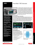
The two-channel Model 2182A Nanovoltmeter
is optimized for making stable, low noise
voltage measurements and for characterizing
low resistance materials and devices reliably
and repeatably. It provides higher measurement
speed and significantly better noise performance
than alternative low voltage measurement
solutions.
The Model 2182A represents the next step
forward in Keithley nanovoltmeter technology,
replacing the original Model 2182 and offering
enhanced capabilities including pulse capability,
lower measurement noise, faster current reversals, and a simplified delta mode for making
resistance measurements in combination with a
reversing current source, such as the Model 6220
or 6221.
• Make low noise measurements at
high speeds, typically just 15nV
p-p noise at 1s response time,
40–50nV p-p noise at 60ms
• Delta mode coordinates
measurements with a reversing
current source at up to 24Hz
with 30nV p-p noise (typical) for
one reading. Averages multiple
readings for greater noise
reduction
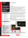
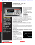
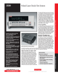
Flexible, Effective Speed/Noise Trade-offs
The Model 2182A makes it easy to choose the best speed/filter combination for a particular application’s response time and noise level requirements. The ability to select from a wide range of response
times allows optimizing speed/noise trade-offs. Low noise levels are assured over a wide range of
useful response times, e.g., 15nV p-p noise at 1s and 40-50nV p-p noise at 60ms are typical. Figure 1
illustrates the Model 2182A’s noise performance.
150
• Synchronization to line provides
110dB NMRR and minimizes
the effect of AC common-mode
currents
• Dual channels support measuring
voltage, temperature, or the ratio
of an unknown resistance to a
reference resistor
• Built-in thermocouple
linearization and cold junction
compensation
100
50
Keithley 2182A
nV
nV/μΩ Meter
0
-50
-100
0
100
Number of Readings
Figure 1. Compare the Model 2182A’s DC noise performance with a nanovolt/micro-ohmmeter’s. All the data shown was taken at 10 readings per second with a low thermal short
applied to the input.
1.888.KEITHLEY (U.S. only)
w w w.keithley.com
Low noise measurements for research, metrology,
Side Textand other low voltage testing applications
Nanovoltmeter
A
G R E A T E R
M E A S U R E
O F
C O N F I D E N C E
LOW LEVEL MEASURE & SOURCE
2182A
Low noise measurements for research, metrology,
Side Textand other low voltage testing applications
2182A
Ordering Information
2182A
Nanovoltmeter
Accessories Supplied
2107-4 Low Thermal Input Cable
with spade lugs, 1.2m (4 ft).
User manual, service
manual, contact cleaner,
line cord, alligator clips.
ACCESSORIES AVAILABLE
2107-30
2182-KIT
2187-4
2188
4288-1
4288-2
7007-1
7007-2
7009-5
8501-1
8501-2
8502
8503
KPCI-488LPA
KUSB-488B
Low Thermal Input Cable with spade lugs,
9.1m (30 ft)
Low Thermal Connector with strain relief
Low Thermal Test Lead Kit
Low Thermal Calibration Shorting Plug
Single Fixed Rack Mount Kit
Dual Fixed Rack Mount Kit
Shielded GPIB Cable, 1m (3.2 ft)
Shielded GPIB Cable, 2m (6.5 ft)
Shielded RS-232 Cable, 1.5m (5 ft)
Trigger Link Cable, 1m (3.2 ft)
Trigger Link Cable, 2m (6.5 ft)
Trigger Link Adapter to 6 female BNC connectors
Trigger Link Cable to 2 male BNC connectors
IEEE-488 Interface/Controller for the PCI Bus
IEEE-488 USB-to-GPIB Interface Adapter
Nanovoltmeter
Reliable Results
Power line noise can compromise measurement accuracy significantly at the nanovolt level. The
Model 2182A reduces this interference by synchronizing its measurement cycle to line, which
minimizes variations due to readings that begin at different phases of the line cycle. The result is
exceptionally high immunity to line interference with little or no shielding and filtering required.
Optimized for Use with Model 6220/6221 Current Sources
Device test and characterization for today’s very small and power-efficient electronics requires sourcing low current levels, which demands the use of a precision, low current source. Lower stimulus
currents produce lower—and harder to measure—voltages across the devices. Linking the Model
2182A Nanovoltmeter with a Model 6220 or 6221 Current Source makes it possible to address both of
these challenges in one easy-to-use configuration.
When connected, the Model 2182A and Model 6220 or 6221 can be operated like a single instrument.
Their simple connections eliminate the isolation and noise current problems that plague other solutions. The Model 2182A/622X combination allows making delta mode and differential conductance
measurements faster and with less noise than the original Model 2182 design allowed. The Model
2182A will also work together with the Model 6221 to make pulse-mode measurements.
The 2182A/622X combination is ideal for a variety of applications, including resistance measurements, pulsed I-V measurements, and differential conductance measurements, providing significant
advantages over earlier solutions like lock-in amplifiers or AC resistance bridges. The 2182A/622X
combination is also well suited for many nanotechnology applications because it can measure
resistance without dissipating much power into the device under test (DUT), which would otherwise
invalidate results or even destroy the DUT.
An Easy-to-Use Delta Mode
Keithley originally created the delta mode method for measuring voltage and resistance for the Model
2182 and a triggerable external current source, such as the Model 2400 SourceMeter instrument.
Basically, the delta mode automatically triggers the current source to alternate the signal polarity, and
then triggers a nanovoltmeter reading at each polarity. This current reversal technique cancels out
SERVICES AVAILABLE
2182A-3Y-EW
1-year factory warranty extended to 3 years
from date of shipment
C/2182A-3Y-ISO 3 (ISO-17025 accredited) calibrations within 3
years of purchase*
TRN-LLM-1-C
Course: Making Accurate Low-Level
Measurements
* Not available in all countries
5nV
LOW LEVEL MEASURE & SOURCE
APPLICATIONS
Research
• Determining the transition
temperature of superconductive
materials
• I-V characterization of a material
at a specific temperature
• Calorimetry
• Differential thermometry
• Superconductivity
• Nanomaterials
Metrology
• Intercomparisons of standard cells
• Null meter for resistance bridge
measurements
1.888.KEITHLEY (U.S. only)
w w w.keithley.com
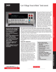
4μV
DC
Measurement
Delta Mode
Measurement
Figure 2. Results from a Model 2182A/6220 using the delta mode to measure a 10mΩ resistor
with a 20µA test current. The free Model 6220/6221 instrument control example start-up
software used here can be downloaded from www.keithley.com.
A
G R E A T E R
M E A S U R E
O F
C O N F I D E N C E
any constant thermoelectric offsets, so the results reflect the true value of
the voltage being measured. The improved delta mode for the Model 2182A
and the Model 622X current sources uses the same basic technique, but the
way in which it’s implemented has been simplified dramatically. The new
technique can cancel thermoelectric offsets that drift over time (not just
static offsets), produces results in half the time of the original technique,
and allows the current source to control and configure the Model 2182A.
Two key presses are all that’s required to set up the measurement. The
improved cancellation and higher reading rates reduce measurement noise
to as little as 1nV.
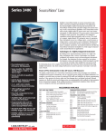
Model 2182A
2182A NANOVOLTMETER
6220 DC AND AC CURRENT SOURCE
Figure 3. It’s simple to connect the Model 2182A to the Model
6220 or 6221 to make a variety of measurements. The instrument
control example start-up software available for the Model 622X
current sources includes a step-by-step guide to setting up the
instrumentation and making proper connections.
Competition
100μs
Trigger Link
GPIB or
Ethernet
DUT
Differential Conductance Measurements
Characterizing non-linear tunneling devices and low temperature devices
often requires measuring differential conductance (the derivative of a
device’s I-V curve). When used with a Model 622X current source, the
Model 2182A is the industry’s fastest, most complete solution for differential conductance measurements, providing 10X the speed and significantly
lower noise than other instrumentation options. There’s no need to
average the results of multiple sweeps, because data can be obtained in a
single measurement pass, reducing test time and minimizing the potential
for measurement error.
Pulsed Testing with the Model 6221
When measuring small devices, introducing
even tiny amounts of heat to the DUT can raise
its temperature, skewing test results or even
destroying the device. When used with the
Model 2182A, the Model 6221’s pulse capability
minimizes the amount of power dissipated into
a DUT. The Model 2182A/6221 combination
synchronizes the pulse and measurement. A
measurement can begin as soon as 16µs after
the Model 6221 applies the pulse. The entire
pulse, including a complete nanovolt measurement, can be as short as 50µs.
Model 622X
RS-232
2182A
2182A in delta mode
0.5μA
Figure 4. The Model 2182A produces the lowest transient currents of any nanovoltmeter available.
In the delta, differential conductance, and pulse
modes, The Model 2182A produces virtually no transient currents, so it’s
ideal for characterizing devices that can be easily disrupted by current spikes
(see Figure 4).
Research Applications
The Model 2182A’s 1nV sensitivity, thermoelectric EMF cancellation, direct
display of “true” voltage, ability to perform calculations, and high measurement speed makes it ideal for determining the characteristics of materials
such as metals, low resistance filled plastics, and high and low temperature
superconductors.
Metrology Applications
The Model 2182A combines the accuracy of a digital multimeter with
low noise at high speeds for high-precision metrology applications. Its
low noise, high signal observation time, fast measurement rates, and
2ppm accuracy provide the most cost-effective meter available today for
applications such as intercomparison of voltage standards and direct
measurements of resistance standards.
Nanotechnology Applications
The Model 2182A combined with the Model 622X current source or Series
2400 SourceMeter® instrument is a highly accurate and repeatable solution
for measuring resistances on carbon nanotube based materials and silicon
nanowires.
1.888.KEITHLEY (U.S. only)
w w w.keithley.com
A
G R E A T E R
M E A S U R E
O F
C O N F I D E N C E
Low noise measurements for research, metrology,
Side Textand other low voltage testing applications
Nanovoltmeter
LOW LEVEL MEASURE & SOURCE
2182A
LOW LEVEL MEASURE & SOURCE
Low noise measurements for research, metrology,
Side Textand other low voltage testing applications
2182A
Nanovoltmeter
Three Ways to Measure Nanovolts
220
DC nanovoltmeters. DC nanovoltmeters
and sensitive DMMs both provide low noise
DC voltage measurements by using long
integration times and highly filtered readings
to minimize the bandwidth near DC.
Unfortunately, this approach has limitations,
particularly the fact that thermal voltages
develop in the sample and connections vary,
so long integration times don’t improve
measurement precision. With a noise
specification of just 6nV p-p, the Model 2182A
is the lowest noise digital nanovoltmeter
available.
215
AC technique. The limitations of the long
integration and filtered readings technique
have led many people to use an AC technique
for measuring low resistances and voltages.
In this method, an AC excitation is applied
to the sample and the voltage is detected
synchronously at the same frequency and
an optimum phase. While this technique
removes the varying DC component, in many
experiments at high frequencies, users can
experience problems related to phase shifts
caused by spurious capacitance or the L/R
time constant. At low frequencies, as the
AC frequency is reduced to minimize phase
shifts, amplifier noise increases.
The current reversal method. The Model
2182A is optimized for the current reversal
method, which combines the advantages of
both earlier approaches. In this technique,
the DC test current is reversed, then the
difference in voltage due to the difference
in current is determined. Typically, this
measurement is performed at a few hertz (a
frequency just high enough for the current
to be reversed before the thermal voltages
can change). The Model 2182A’s low noise
performance at measurement times of a
few hundred milliseconds to a few seconds
means that the reversal period can be set
quite small in comparison with the thermal
time constant of the sample and the connections, effectively reducing the impact of
thermal voltages.
30
Temperature
(°C)
25
210
20
205
15
200
10
Voltage
(nV)
195
5
190
0
185
–5
180
0
8
17
–10
25 33 42 50 58 67 75 83 92 100 108 117 125
Minutes
Figure 5. The Model 2182A’s delta mode provides extremely stable results, even in the presence of large ambient temperature changes. In this challenging example, the 200nV signal
results from a 20µA current sourced by a Model 6221 through a 10mΩ test resistor.
Optional Accessory: Model 2187-4 Low Thermal
Test Lead Kit
The standard cabling provided with the Model
2182A Nanovoltmeter and Model 622X Current
Sources provides everything normally needed
to connect the instruments to each other and to
the DUT. The Model 2187-4 Low Thermal Test
Lead Kit is required when the cabling provided
may not be sufficient for specific applications,
such as when the DUT has special connection
requirements. The kit includes an input cable
with banana terminations, banana extensions,
sprung-hook clips, alligator clips, needle probes,
and spade lugs to accommodate virtually any
DUT. The Model 2187-4 is also helpful when the
DUT has roughly 1GΩ impedance or higher.
In this case, measuring with the Model 2182A
Figure 6. Model 2187-4 Test Lead Kit
directly across the DUT will lead to loading
errors. The Model 2187-4 Low Thermal Test Lead Kit provides a banana cable and banana jack
extender to allow the Model 2182A to connect easily to the Model 622X’s low impedance guard
output, so the Model 2182A can measure the DUT voltage indirectly. This same configuration also
removes the Model 2182A’s input capacitance from the DUT, so it improves device response time,
which may be critical for pulsed measurements.
Figure 7. Model 2182A rear panel
1.888.KEITHLEY (U.S. only)
w w w.keithley.com
A
G R E A T E R
M E A S U R E
O F
C O N F I D E N C E
2182A
Nanovoltmeter
Volts Specifications (20% over range)
Channel 2 6, 10
100.00000 mV
1.0000000 V
10.000000 V
Input
Resistance
>10 GΩ
>10 GΩ
>10 GΩ
>10 GΩ
10 MΩ ±1%
Resolution
1 nV
10 nV
100 nV
1 µV
10 µV
10 nV
100 nV
1 µV
>10 GΩ
>10 GΩ
>10 GΩ
10 + 6
7+2
2 + 15
25 + 6
18 + 2
18 + 2
30 + 7
25 + 2
25 + 2
Temperature
Coefficient
0°–18°C & 28°–50°C
(1 + 0.5)/°C
(1 + 0.2)/°C
(1 + 0.1)/°C
(1 + 0.1)/°C
(1 + 0.5)/°C
40 + 7
32 + 3
32 + 3
(1 + 1 )/°C
(1 + 0.5)/°C
(1 + 0.5)/°C
CHANNEL 1/CHANNEL 2 RATIO: For input signals ≥1% of the range, Ratio Accuracy =
±{[Channel 1 ppm of Reading + Channel 1 ppm of Range * (Channel 1 Range/Channel 1 Input)] + [Channel 2 ppm of Reading + Channel 2 ppm of Range * (Channel 2 Range/Channel 2 Input)]}.
DELTA (hardware-triggered coordination with Series 24XX, Series 26XXA, or Series 622X current sources for low noise R measurement):
Accuracy = accuracy of selected Channel 1 range plus accuracy of I source range.
DELTA MEASUREMENT NOISE WITH 6220 or 6221: Typical 3nVrms / Hz (10mV range)21. 1Hz achieved with 1PLC, delay = 1ms, RPT filter = 23 (20 if 50Hz).
PULSE-MODE (WITH 6221): Line synchronized voltage measurements within current pulses from 50µs to 12ms, pulse repetition rate up to 12Hz.
PULSE MEASUREMENT NOISE (typical rms noise, R DUT<10Ω): ±(0.009ppm of range*) / meas_time / pulse_avg_count + 3nV** / (2 · meas_time · pulse_avg_count) for 10mV range.
* 0.0028ppm for the 100mV range, 0.0016ppm for ranges 1V and above.
** 8nV/ Hz for ranges above 10mV . meas_time (seconds) = pulsewidth – pulse_meas_delay in 33µs incr.
DC Noise Performance 7 (DC noise expressed in volts peak-to-peak)
Response time = time required for reading to be settled within noise levels from a stepped input, 60Hz operation.
Channel 1
Response
Range
Time
NPLC, Filter
10 mV
100 mV
1V
10 V
25.0 s
5, 75
6 nV
20 nV
75 nV
750 nV
4.0 s
5, 10
15 nV
50 nV
150 nV
1.5 µV
1.0 s
1, 18
25 nV
175 nV
600 nV
2.5 µV
667 ms
1, 10 or 5, 2
35 nV
250 nV
650 nV
3.3 µV
60 ms
1, Off
70 nV
300 nV
700 nV
6.6 µV
Channel 2 6, 10
25.0 s
5, 75
—
150 nV
200 nV
750 nV
4.0 s
5, 10
—
150 nV
200 nV
1.5 µV
1.0 s
1, 10 or 5, 2
—
175 nV
400 nV
2.5 µV
85 ms
1, Off
—
425 nV
1 µV
9.5 µV
Analog
Filter
Off
Off
Off
Off
On
On
—
—
—
—
TEMPERATURE (Thermocouples) 12
TYPE
J
K
N
T
E
R
S
B
RANGE
–200 to +760°C
–200 to +1372°C
–200 to +1300°C
–200 to +400°C
–200 to +1000°C
0 to +1768°C
0 to +1768°C
+350 to +1820°C
RESOLUTION
0.001 °C
0.001 °C
0.001 °C
0.001 °C
0.001 °C
0.1 °C
0.1 °C
0.1 °C
1.888.KEITHLEY (U.S. only)
w w w.keithley.com
CMRR 9
140 dB
140 dB
140 dB
140 dB
140 dB
110 dB
100 dB
90 dB
60 dB
140 dB
140 dB
140 dB
140 dB
60Hz (50Hz) Operation
Digital
Filter
100
100
100
100
100
100
Function
DCV Channel 1,
Channel 2,
Thermocouple
Digits
7.5
7.5 17, 19
6.5 18, 19
6.5 18, 19, 20
5.5 17, 19
4.5 16, 17, 19
7.5
7.5 17, 19
6.5 18
6.5 18, 20
5.5 17
4.5 17
6.5
Channel 1/Channel 2 (Ratio),
Delta with 24XX, Scan
(Displayed in °C, °F, or K. Accuracy based on
ITS-90, exclusive of thermocouple errors.)
NMRR 8
110 dB
100 dB
95 dB
90 dB
60 dB
Operating Characteristics 13, 14
VOLTAGE NOISE VS. SOURCE RESISTANCE 11
(DC noise expressed in volts peak-to-peak)
Source
Resistance
Noise
0 Ω
6 nV
100 Ω
8 nV
1 kΩ
15 nV
10 kΩ
35 nV
100 kΩ
100 nV
1 MΩ
350 nV
100 V
75 µV
75 µV
100 µV
150 µV
300 µV
ACCURACY
90 Day/1 Year
23° ±5°C
Relative to Simulated
Reference Junction
±0.2 °C
±0.2 °C
±0.2 °C
±0.2 °C
±0.2 °C
±0.2 °C
±0.2 °C
±0.2 °C
Delta with 622X
Readings/s
3
(2)
6
(4)
18
(15)
45
(36)
80
(72)
115 (105)
1.5 (1.3)
2.3 (2.1)
8.5 (7.5)
20
(16)
30
(29)
41
(40)
47 (40.0) 22
System Speeds 13, 15
RANGE CHANGE TIME: 14
<40 ms (<50 ms).
<45 ms (<55 ms).
FUNCTION CHANGE TIME: 14
<60 ms (<70 ms).
AUTORANGE TIME: 14
ASCII READING TO RS-232 (19.2K Baud):
40/s
(40/s).
120/s
(120/s).
MAX. INTERNAL TRIGGER RATE: 16
16
120/s
(120/s).
MAX. EXTERNAL TRIGGER RATE:
A
G R E A T E R
M E A S U R E
O F
C O N F I D E N C E
PLCs
5
5
1
1
0.1
0.01
5
5
1
1
0.1
0.01
1
LOW LEVEL MEASURE & SOURCE
Channel 1
Range
10.000000 mV 2, 3, 4
100.00000 mV
1.0000000 V
10.000000 V
100.00000 V 4
Accuracy: ±(ppm of reading + ppm of range)
(ppm = parts per million) (e.g., 10ppm = 0.001%)
24 Hour 1
90 Day
1 Year
2 Year
TCAL ±1°C
TCAL ±5°C
TCAL ±5°C
TCAL ±5°C
20 + 4
40 + 4
50 + 4
60 + 4
10 + 3
25 + 3
30 + 4
40 + 5
7+2
18 + 2
25 + 2
32 + 3
18 + 2
25 + 2
32 + 3
2 + 15
10 + 3
25 + 3
35 + 4
52 + 5
Model 2182A
Side specifications
Text
CONDITIONS: 1PLC with 10 reading digital filter or 5PLC with 2 reading digital filter.
2182A
Nanovoltmeter
Model
Model
2182A
Side
specifications
specifications
Text
Measurement Characteristics
GENERAL
POWER SUPPLY: 100V/120V/220V/240V.
LINE FREQUENCY: 50Hz, 60Hz, and 400Hz, automatically sensed at power-up.
POWER CONSUMPTION: 22VA.
MAGNETIC FIELD DENSITY: 10mV range 4.0s response noise tested to 500 gauss.
OPERATING ENVIRONMENT: Specified for 0° to 50°C. Specified to 80% RH at 35°C.
STORAGE ENVIRONMENT: –40° to 70°C.
EMC: Complies with European Union Directive 89/336/EEC (CE marking requirement), FCC
part 15 class B, CISPR 11, IEC 801-2, IEC-801-3, IEC 801-4.
SAFETY: Complies with European Union Directive 73/23/EEC (low voltage directive); meets
EN61010-1 safety standard. Installation category I.
VIBRATION: MIL-T-28800E Type III, Class 5.
WARM-UP: 2.5 hours to rated accuracy.
DIMENSIONS: Rack Mounting: 89mm high × 213mm wide × 370mm deep (3.5 in × 8.375
in × 14.563 in). Bench Configuration (with handles and feet): 104mm high × 238mm
wide × 370mm deep (4.125 in × 9.375 in ×14.563 in).
SHIPPING WEIGHT: 5kg (11 lbs).
A/D LINEARITY: ±(0.8ppm of reading + 0.5ppm of range).
FRONT AUTOZERO OFF ERROR
10mV–10V:
Add ±(8ppm of range + 500µV) for <10 minutes and ±1°C.
NOTE: Offset voltage error does not apply for Delta Mode.
AUTOZERO OFF ERROR
10mV:
Add ±(8ppm of range + 100nV) for <10 minutes and ±1°C.
100mV–100V: Add ±(8ppm of range + 10µV) for <10 minutes and ±1°C.
NOTE: Offset voltage error does not apply for Delta Mode.
INPUT IMPEDANCE
10mV–10V:
>10GΩ, in parallel with <1.5nF (Front Filter ON).
10mV–10V:
>10GΩ, in parallel with <0.5nF (Front Filter OFF).
100V:
10MΩ ±1%.
DC INPUT BIAS CURRENT: <60pA DC at 23°C, –10V to 5V. <120pA @ 23°C, 5V to 10V.
COMMON MODE CURRENT: <50nA p-p at 50Hz or 60Hz.
INPUT PROTECTION: 150V peak to any terminal. 70V peak Channel 1 LO to Channel 2 LO.
CHANNEL ISOLATION: >10GΩ.
EARTH ISOLATION: 350V peak, >10GΩ and <150pF any terminal to earth. Add 35pF/ft with
Model 2107 Low Thermal Input Cable.
NOTES
1. Relative to calibration accuracy.
2. With Analog Filter on, add 20ppm of reading to listed specification.
3. When properly zeroed using REL function. If REL is not used, add 100nV to the range accuracy.
4. Specifications include the use of ACAL function. If ACAL is not used, add 9ppm of reading/°C
from TCAL to the listed specification. TCAL is the internal temperature stored during ACAL.
5. For 5PLC with 2-reading Digital Filter. Use ±(4ppm of reading + 2ppm of range) for 1PLC with
10-reading Digital Filter.
6. Channel 2 must be referenced to Channel 1. Channel 2 HI must not exceed 125% (referenced
to Channel 1 LO) of Channel 2 range selected.
7. Noise behavior using 2188 Low Thermal Short after 2.5 hour warm-up. ±1°C. Analog Filter off.
Observation time = 10× response time or 2 minutes, whichever is less.
8. For LSYNC On, line frequency ±0.1%. If LSYNC Off, use 60dB.
9. For 1kΩ unbalance in LO lead. AC CMRR is 70dB.
10. For Low Q mode On, add the following to DC noise and range accuracy at stated response
time: 200nV p-p @ 25s, 500nV p-p @ 4.0s, 1.2µV p-p @ 1s, and 5µV p-p @ 85ms.
11. After 2.5 hour warm-up, ±1°C, 5PLC, 2 minute observation time, Channel 1 10mV range only.
12. For Channel 1 or Channel 2, add 0.3°C for external reference junction. Add 2°C for internal
reference junction.
13. Speeds are for 60Hz (50Hz) operation using factory defaults operating conditions (*RST).
Autorange Off, Display Off, Trigger Delay = 0, Analog Output off.
14. Speeds include measurements and binary data transfer out the GPIB. Analog Filter On, 4
readings/s max.
15. Auto Zero Off, NPLC = 0.01.
16. 10mV range, 80 readings/s max.
17. Sample count = 1024, Auto Zero Off.
18. For LSYNC On, reduce reading rate by 15%.
19. For Channel 2 Low Q mode Off, reduce reading rate by 30%.
20. Front Auto Zero off, Auto Zero off.
21. Applies to measurements of room temperature resistances <10Ω, Isource range ≤20µA.
22. Display off, delay 1ms.
Analog Output
MAXIMUM OUTPUT: ±1.2V.
ACCURACY: ±(0.1% of output + 1mV).
OUTPUT RESISTANCE: 1kΩ ±5%.
GAIN: Adjustable from 10 –9 to 106. With gain set to 1, a full range input will produce a 1V output.
OUTPUT REL: Selects the value of input that represents 0V at output. The reference value can be
either programmed value or the value of the previous input.
Triggering and Memory
WINDOW FILTER SENSITIVITY: 0.01%, 0.1%, 1%, 10%, or full scale of range (none).
READING HOLD SENSITIVITY: 0.01%, 0.1%, 1%, or 10% of reading.
TRIGGER DELAY: 0 to 99 hours (1ms step size).
EXTERNAL TRIGGER DELAY: 2ms + <1ms jitter with auto zero off, trigger delay = 0.
MEMORY SIZE: 1024 readings.
Math Functions
Rel, Min/Max/Average/Std Dev/Peak-to-Peak (of stored reading), Limit Test, %, and mX+b with userdefined units displayed.
Remote Interface
LOW LEVEL MEASURE & SOURCE
Keithley 182 emulation.
GPIB (IEEE-488.2) and RS-232C.
SCPI (Standard Commands for Programmable Instruments).
1.888.KEITHLEY (U.S. only)
w w w.keithley.com
A
G R E A T E R
M E A S U R E
O F
C O N F I D E N C E