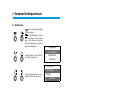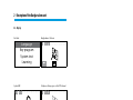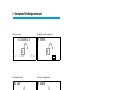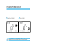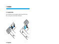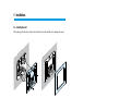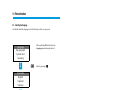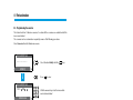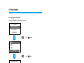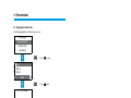
1
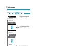
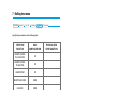
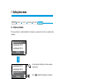
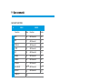
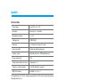
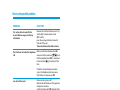
Burglar-alarm unit
5739 34/35
Installation manual
Part. U3500A - 11/08-01 PC
Contents
1 - Introduction __________________________________________________ 5
1.1 - Remarks and recommendaions ______________________________________ 5
1.2 - Contents of package ______________________________________________ 5
2 - Description of the Burglar-alarm unit _________________________________ 6
2.1 - Overview ________________________________________________________ 6
2.2 - Navigation keys __________________________________________________ 7
2.3 - Display__________________________________________________________ 8
2.4 - Main functions __________________________________________________ 11
2.5 - Example on how to use the burglar-alarm unit ________________________ 13
3 - Installation _________________________________________________ 14
3.1 - Back view of unit_________________________________________________ 14
3.2 - Connecting the battery ___________________________________________ 15
3.3 - Tamper device___________________________________________________ 15
3.4 - Installing the unit ________________________________________________ 16
3.5 - Connecting the telephone line _____________________________________ 16
4 - First activation _______________________________________________ 17
4.1 - Selecting the language ___________________________________________ 18
4.2 - Learning _______________________________________________________ 19
4.3 - Escaping from the maintenance menu _______________________________ 21
4.4 - System test _____________________________________________________ 22
4.5 - Programmaing the scenarios _______________________________________ 24
4.6 - Key program - transponder ________________________________________ 25
4.7 - Key program - numeric code _______________________________________ 26
4.8 - Key limitation ___________________________________________________ 27
4.9 - Setting the date and hour _________________________________________ 29
5 - Programming ________________________________________________ 30
5.1 - Programming from personal computer ______________________________ 30
5.2 - Programming from keypad ________________________________________ 32
5.3 - Programming menu diagram ______________________________________ 34
6 - Burglar-alarm menu ___________________________________________ 35
6.1 - Scenarios _______________________________________________________ 35
6.2 - Zones__________________________________________________________ 36
6.3 - Devices ________________________________________________________ 37
6.4 - Event memory __________________________________________________ 38
6.5 - Date and hour ___________________________________________________ 39
6.6 - Automations ____________________________________________________ 40
6.7 - Settings ________________________________________________________ 42
6.8 - Maintenance (for installer only) _____________________________________ 43
6.9 - Loss of Maintenance Code _________________________________________ 44
3
Contents
7 - Dialling device menu ___________________________________________ 45
7.1 - Jolly number ____________________________________________________ 45
7.2 - Index book _____________________________________________________ 47
7.3 - Set calls ________________________________________________________ 48
7.4 - Vocal messages __________________________________________________ 51
7.5 - Telephone function ______________________________________________ 53
7.6 - Telephone commands ____________________________________________ 55
8 - Operation___________________________________________________ 56
8.1 - Activation / disActivation antifurto __________________________________ 56
8.2 - Deactivating - activating zones _____________________________________ 58
8.3 - Sound signalling _________________________________________________ 61
8.4 - Consulting the event memory in case of an alarm ______________________ 62
8.5 - Sending telephone commands _____________________________________ 65
8.6 - Semplified 99 codes ______________________________________________ 66
8.7 - Asking for information - code 92 ____________________________________ 67
8.8 - Replying to a call from the Unit _____________________________________ 68
9 - Open commands ______________________________________________ 69
9.1 - The open web net code ___________________________________________ 69
Appendix _____________________________________________________ 81
Technical data _______________________________________________________ 81
Standard references __________________________________________________ 81
How to solve possible problems ______________________________________ 82
4
1 - Introduction
1.1 - Remarks and recommendaions
Before starting the installation, it is important to read this manual carefully since the guarantee
may automatically expire due to negligence, wrong or improper use and tampering of circuit by
unauthorized staff. Moreover, it expires when the damage is due to strong accidental overcurrents
on the power supply mains or telephone line.Therefore, if the burglar-alarm unit is installed in a
place that is subject to violent atmospheric discharges (storms), appropriate protections must
be installed on the power supply line and telephone line by carrying out the grounding properly
and complying with the CEI requirements.
1.2 - Contents of package
The Unit package contains:
• Burglar-alarm unit with dialling device 5739 34/35.
• Battery.
• Installation manual.
• User manual.
• CD-ROM containing SecurityConfig software and manuals in PDF format.
5
2 - Description of the Burglar-alarm unit
2.1 - Overview
1
2
3
OK
1
2
3
4
5
6
7
8
9
0
4
6
5
P
1 Graphic display: displays the messages that can control programming operations and events
that have previously taken place (more information on the next page).
2 Navigation keypad: lets you navigate through the menus and enables the confirmation or
cancellation of programming operations.
3 Alphanumeric keypad: allows manual entering of all programming operations that require
the use of numbers and/or symbols.
4 Microphone : used for recording the messages and for remote room monitoring by
telephone.
5 Transponder reader: receives the ON/OFF commands of the burglar-alarm system directly
from the transponder keys.
6 Loudspeaker: allows listening to the recorded messages and the scattering of room vocal
messages by telephone.
6
2 - Description of the Burglar-alarm unit
2.2 - Navigation keys
- Key for entering the displayed
selection or data.
- Key for deleting the selection
and for returning to the previous
page – hold down to escape from
the programming menus and to go
back to the initial page.
Language
Key program
System test
Learning
Scroll keys allow you to scroll the
list of items in the menus.
01
: Entrance
: Perimeter
03
: Night
Exclude
02
Selection keys allow you to select
functions included in the menus.
7
2 - Description of the Burglar-alarm unit
2.3 - Display
First start
Burglar alarm / 24 hours
Language
Key program
System test
Learning
System OFF
Telephone call in progress on the PSTN channel
1234–– –– –– ––
15/11/2008
1234–– –– –– ––
15:02
System ON
8
1234–– –– –– ––
Zones 2 and 3 disabled
1234–– –– –– ––
1234–– –– –– ––
15/11/2008
15/11/2008
15:02
15:02
2 - Description of the Burglar-alarm unit
Division scenario
Unit battery dead or damaged
SCENARIO 4
15/11/2008
1234–– –– –– ––
15:03
System battery dead
1234–– –– –– ––
General alarm*
1234–– –– –– ––
Power line voltage failure
1234–– –– –– ––
System test
VERIFY THE
SENSORS
HW
M30
*.**
**.**
* General alarm, indicates a technical alarm, a signal of a non-system battery (or radio device) fault
or a tamptest signal with the system switched OFF.
9
2 - Description of the Burglar-alarm unit
Telephone calls disabled
Sensor disabled
1234–– –– –– ––
1234–– –– –– ––
15/11/2008
15/11/2008
15:04
15:04
Important Unit functions are disabled; disable only if extremely necessary.
10
2 - Description of the Burglar-alarm unit
2.4 - Main functions
General features
• Burglar-alarm unit with integrated telephone dialling device.
• Self-learning of the system and configuration display.
• Controllable from transponder and keypad.
• Independent management of each sensor.
• Programmable from PC.
• Detailed history of events and alarm history.
• Editing of alarm messages.
• Telephone index book for alarm forwarding.
• Connection with surveillance control units with remote assistance function.
• Block for 1 minute of the possibility of switching ON/ OFF or access to the navigation menu, if
there is an key error three times in succession (from keypad or transponder).
• Combination of any scenario, zone and sensor name.
• Each individual sensor can be deactivated by sending a command from the control unit
keypad.
• Can send a test call, with programmable timing, to portal or surveillance Control unit.
• Signal of no interconnection with: sensors with system switched OFF a signal icon is displayed,
with system switched ON an alarm is generated.
• Division of zones directly from the Control unit keypad.
Burglar-alarm system unit:
The Unit manages a total of 10 zones:
• Zone 0 is reserved for the connectors (max. 9);
• Zones 1 – 8 are reserved for the sensors;
• Zone 9 is reserved for the technical/auxiliary alarms (gas detector, etc.).
It performs the following functions:
• Management of the events communicated by the sensors, including the possibility to determine
if and when the alarm will go on.
• Zones 1 – 8 can be divided according to the user’s needs.
• Can create up to 16 division scenarios and activate them as required
• A set division can be linked to each key; also use of the key can be limited to set days of the
week and with a precise time range.
11
2 - Description of the Burglar-alarm unit
• Lets the user carry out any automation in case of an event recorded by the burglar-alarm system
(e.g. turning the lights ON in a tampering alarm zone).
• All editing steps are guided and shown through the display.
Telephone dialling device
Provides bi-directional communication between the user and the home automation In One by
Legrand®:
• In case of alarm detected by the burglar alarm, it will automatically dial the telephone numbers
previously programmed by the user and will notify the type of event occurred through a vocal
message.
• It can be called by the user who can send commands to the automation system and burglaralarm system through predefined codes.
• It allows you to know - by telephone - the status of the burglar-alarm and automation
system.
• It lets you connect the portal and makes available the web service, for example the remote
assistance service as well as the possibility to download the history of events.
• It allows automatically sending the alarm and event signals to surveillance control units which
use the Contact ID protocol and requesting and setting its parameters.
12
2 - Description of the Burglar-alarm unit
2.5 - Example on how to use the burglar-alarm unit
Example 1: intrusion alarm
Burglar-alarm unit
OK
IR Sensor
1
2
3
4
5
6
7
8
9
0
Fixed telephone
Example 2: enabling/disabling the burglar alarm upon user’s request
Burglar-alarm unit
IR Sensor
OK
1
2
3
4
5
6
7
8
9
0
Contact
interface
Fixed telephone
13
3 - Installation
3.1 - Back view of unit
Battery
housing
Telephone
line IN
Telephone
line OUT
b
a
b
Tamper line
(see note)
Local tamper
T1
Reset
pushbutton
T1
OFF
Slide switch
ON OFF
ON
SCS Bus
Serial connector for
programming from PC
(with cable 0492 34)
NOTE: The Unit is supplied with tamper line terminals (– / T1) circuited for using the local
tamper T1 (wall-mounting installation with metal base).
14
3 - Installation
3.2 - Connecting the battery
Connect the battery to its connector, minding the polarities shown inside the housing.
Before connecting, make sure the slide switch is in OFF position.
3.3 - Tamper device
The Control unit should be protected against attempts at tampering by installing device item
6831 64 on the back.
To mount the tamper device remove the protection plug from the Control unit turning it by 90°.
If the flush-mounted box is flush fitted in the wall, before inserting the rod in the housing, cut it
at the first notch as shown in the figure.
Insert the rod, lock it by turning it by 90° and extract it completely.
52mm
< 60mm
15
3 - Installation
3.4 - Installing the unit
After making all connections, fasten the Unit to the base. Be careful not to damage the wires.
3.5 - Connecting the telephone line
The burglar-alarm unit must be the first component of the internal telephone system: it
should therefore be connected before any other device (telephone, fax machine or answering
machine).
A suitable overcurrent protection on the telephone line is required (e.g. 038 28).
038 28
OK
1
2
3
4
5
6
7
8
9
0
16
4 - First activation
When the Unit is switched ON for the first time, the Maintenance menu is shown; the slide switch
on the back is in OFF position.
To activate the Unit and make it operational:
• Choose the language.
• Have the Unit execute the learning.
• Flip the slide switch to ON.
• Press
twice to escape from the maintenance menu.
• Go back to the maintenance menu.
• Test the system by verifying the sensors.
• Program a transponder key or a numeric code.
• Enter hour and date.
• Edit the names of the zones, devices and division scenarios.
17
4 - First activation
4.1 - Selecting the language
Use this function if the language set at the factory is not the one you need.
Language
Key program
System test
Learning
When switching ON the first time, the
Language menu is already selected
Enter by pressing
Deutsche
English
Espanol
Français
Choose required language
Deutsche
English
Espanol
Français
Enter by pressing
ATTENTION
the key OK
will modify
all the names
18
A check page is displayed, which allows you to
choose if you want to reinitialize all set names
4 - First activation
4.2 - Learning
This function makes the burglar-alarm unit recognize all devices included in the burglar-alarm
system, hence identifying its classification (IR sensor, internal siren...etc.) and assigned zone. The
configuration is stored by the Unit and can be edited according to the current requirements.
Language
Key program
System test
Learning
Select Learning
Language
Key program
System test
Learning
Press
Z : 0
to enter
N : 1
device AI
t a m p : O F F
automatic
After pressing
figure opposite
Press
LEARNING
ENDED
NO PROBLEM
NEXT
, the display looks like the
to start the learning function
At the end, this message will appear:
LEARNING
ENDED
NO PROBLEM
(instead, if the message “tamper problem”
appears, press , press
and, with the side
go to the manual configuration and
arrow
check the device showing “tamp: ON” with the
down arrow. Eliminate the problem and repeat
the automatic learning function)
19
4 - First activation
At the end of the system learning the request to send the configuration to display devices
(e.g. Keypad connector with display) appears. This will let the devices not only show the alarmgiven signal but also indicate the zone and the sensor which detected it.
SEND
CONFIGURATION?
send
= OK
not send = CLEAR
If there are display devices in the system:
Press
to enter
On the contrary
Press
to cancel
PREPARE
SYSTEM
send
= OK
not send = CLEAR
Set up the devices to receive the configuration
as indicated in their installation manuals
Press
Press
TRASMISSION
ERROR
config. TX = OK
exit conf. = CLEAR
to enter
to cancel
If the page at the side appears make sure that
all the devices are correctly connected to the bus
and ready to receive the configuration
Press
Press
to enter
to cancel
SYSTEM
CONFIG. OK
If you modify the system, by adding or removing devices, it is necessary to execute the selflearning function in order to update the configuration of the system stored by the Unit.
20
4 - First activation
4.3 - Escaping from the maintenance menu
Flip the slide
switch to ON
T1
OFF
ON
Language
Key program
System test
Learning
Press
to escape from the
Maintenance menu
Date and hour
Automations
Settings
Maintenance
Hold down
initial page
to go back to the
1 2 3 4 –– –– –– ––
16 / 11 / 08
08 : 11
21
4 - First activation
4.4 - System test
Return to Maintenance menu as described hereinafter and select System Test; this function verifies
the correct operation of the sensors without causing alarms.
1 2 3 4 –– –– –– ––
16 / 11 / 08
08 : 11
Press
Code/Key
*
1
2
3
4
5
6
7
8
9
Enter the Maintenance Code
(basic 00000)
0
SELECT
Antitheft
Communicator
Date and hour
Automations
Settings
Maintenance
Language
Key program
System test
Learning
22
Select the Burglar alarm (Antitheft) menu and
to enter
press
Select the Maintenance menu and press
to enter
Enter System test.
After checking the system, escape from the
Maintenance menu as described in par. 4.3
4 - First activation
Execute the checks as shown below:
The red LED should light up when passing through the area protected by the IR sensor.
The red LED of the contact interface should light up when opening the windows or entrance door.
675 13
23
4 - First activation
4.5 - Programmaing the scenarios
The Control unit has 16 division scenarios. As a basis all the scenarios are enabled and all the
zones are activated.
The scenarios can be customised as required by means of the following procedure.
Select Scenarios from the Maintenance menu
01
: SCENARIO No1
________
Select function Modify with the
keys
Modify
Press
01
: SCENARIO No1
12345678
Memorize
1
2
3
4
5
6
7
8
9
With the numeric keys select the zones which
must not be activated
0
Press
01
to enter
: SCENARIO No1
________
Disable
24
to enter
When the scenarios have been customised,
hold down the
pushbutton until the initial
page appears
4 - First activation
4.6 - Key program - transponder
Select Key program from the Maintenance menu
Language
Key program
System test
Learning
Press
to enter
Press
again
01
: Key 1
: Key 2
03
: Key 3
02
New
Key program
WAITING KEY...
1
2
3
4
5
6
7
8
9
0
P
01
: transponder
: Key 2
03
: Key 3
Disable
02
Bring the transponder key (less than
one centimeter) near the reader. When
programming is completed, Programming
performed appears on the display.
Whenever the transponder has already been
saved the control unit will return to the list
of keys showing the existing one in case you
want to modify it.
The transponder so programmed will be
recognised by all the system readers
When key programming is completed, hold
pushbutton until the initial page
down the
appears
Notation on transponder use:
To enable or disable the burglar alarm, press the burglar-alarm unit
transponder key near the reader for about 2 seconds.
or
key. Then, bring the
25
4 - First activation
4.7 - Key program - numeric code
Select Key program from the Maintenance menu
Language
Key program
System test
Learning
Press
to enter
Press
again
01
: Key 1
: Key 2
03
: Key 3
02
New
KEY PROGRAM
WAITING
KEY
Press the
key
KEY PROGRAM
ENTER CODE
1
2
3
4
5
6
7
8
9
0
Type the 5-figure numeric code; whenever the
code has already been used the control unit will
return to the list of keys showing the existing one
in case you want to modify it
01
: Key 1
: Key 2
03
: Key 3
Disable
02
When key programming is completed, hold
down the
pushbutton until the initial page
appears
Notation on numeric code use:
To enable or disable the burglar alarm, press the burglar-alarm unit
26
key, then type the code.
4 - First activation
4.8 - Key limitation
The use of each key can be limited to some days of the week, to the activation of just some zones
of the system and with a set time range.
In the case of access limitation to just some zones of the system, the key cannot switch ON, OFF
and modify the system division.
Language
Key program
System test
Learning
Select Key program from the Maintenance
menu
Press
to enter
01
: __ __ __ __ __ __
: __ __ __ __ __ __
03
: __ __ __ __ __ __
Disable
02
Select the key to limit using the
keys
01
: __ __ __ __ __ __
: __ __ __ __ __ __
03
: __ __ __ __ __ __
Disable
02
Select function Select with the
keys
01
: __ __ __ __ __ __
: __ __ __ __ __ __
03
: __ __ __ __ __ __
Select
02
Press
to enter
NEXT
27
4 - First activation
IR
CH
L M M G V S D
– – – – – – –
00:00 – 23:59
1
2
3
4
5
6
7
8
9
0
With the numeric keys select the days when
the key cannot be used.
(1=Monday; 2=Tuesday etc.)
Press
IR
CH
L – M – V – –
1 2 3 4 – – –
00:00 – 23:59
to enter
The use of the key has been limited to Monday,
Wednesday and Friday
Press
to enter
IR
CH
L – M – V – –
1 2 3 4 – – –
00:00 – 23:59
1
2
3
4
5
6
7
8
9
Or, using the
keys select one of the 16
available scenarios
0
IR
CH
L – M – V – –
1 2 – 4 – – –
00:00 – 23:59
IR
CH
L – M – V – –
1 2 – 4 – – –
09:00 – 13:00
28
Press the numeric keys corresponding to the
zones which must not be activated by the key
When switching the system ON, the key will only
activate zones 1, 2 and 4
Press
1
2
3
4
5
6
7
8
9
0
to enter
Type the time when the time band in which
the key will be enabled starts and ends
The key can be used from 09:00 to 13:00
Press
to enter
to return to the page which presents
Press
the list of keys
4 - First activation
4.9 - Setting the date and hour
In order for the system to constantly keep all stored events under control, it is important to set
the correct date and hour.
SELECT
Antitheft
Communicator
Enter Burglar alarm (Antitheft)
Scenarios
Zones
Devices
Event memory
Select Date and hour
Zones
Devices
Event memory
Date and hour
Enter
03 : 05
01/01/00
Saturday
SLAVE
1
2
3
4
5
6
7
8
9
Set the date and hour (day/month/year) by
using the alphanumeric keypad.
(to set SLAVE/MASTER, see par. 6.5)
0
17 : 07
21/11/08
Saturday
MASTER
Press
to enter; the day of the week is
automatically updated
29
5 - Programming
5.1 - Programming from personal computer
Type of program
The Unit can be programmed by using the SecurityConfig software.
Programming from a PC requires a cable 0492 34, for the connection between the Unit 6-way
connector and a PC USB port.
Connection is carried out as follows:
Use the maintenance code to enter the Maintenance using the Maintenance menu, take the
Unit OFF the bracket.
Language
Key program
System test
Learning
Start SecurityConfig program.
Connect cable when requested and then follow the program procedure
b
a
b
T1
0492 34
OFF
ON
For further information, see SecurityConfig software manual.
30
5 - Programming
Firmware update
This function allows updating the Unit software with its latest release. Such update allows bringing
in improvements as well as new Unit functions.
The latest firmware releases are available at www.legrandelectric.com
Before starting the firmware updating procedure position the slide switch on OFF
For further information, see SecurityConfig software manual.
Programming of parameters
This section of the program allows complete editing of each parameter of the Unit with remarkable
simplicity.
It is possible to receive the existing configuration from the Unit, change it and send all changes to
the Unit (in this step, the software executes a compatibility comparison between the implemented
project and the installed system) or save the configuration in a file in order to change it later on
or keep it as a backup copy to retrieve the previous configuration.
Every time the configuration is modified by means of SecurityConfig, relearn the
system and confirm the sending of the configuration.
For further information, see SecurityConfig software manual.
Programming of messages
This program function allows easy management of vocal messages of the Unit. The commands
that are available are as follows:
• Send: transfers the vocal messages from the PC to the Unit
• Listen: lets you listen to the vocal messages directly from the Unit loudspeaker
• Receive: transfers all vocal messages from the Unit to the PC, letting you change and save it
as a project file
• Import wav: lets you import audio files with the extension .wav. The duration of imported files
must not be longer than the one suggested for each message
• Listen: lets you listen to the vocal messages from the PC loudspeakers.
• Record: for recording messages through a microphone connected to the PC.
For further information, see SecurityConfig software manual.
31
5 - Programming
5.2 - Programming from keypad
On completion of operations described in section “First activation”, it will be possible to access
the programming menus and execute a great number of editings that will allow you to fully use
the burglar-alarm unit features and therefore meet the user’s needs.
Two programming levels are required:
• level 1 (user), allows access to the functions used to operate the Unit. It does not allow access
to the Maintenance and Command menus. It allows access, though with partial use, to the
Automation menus (enabling and disabling) and Alarms memory (deleting is not allowed), can
also rename and enable the scenarios and keys and update the numeric codes.
The user can access the level only:
From the keypad
Press OK then type the user code (based 00000).
Entering an incorrect code three times in succession the Control unit prevents the enabling
of other codes for 1 minute.
–– –– –– –– –– –– ––
17 / 11 / 08
08 : 13
Key/Code
*
1
2
3
4
5
6
7
8
9
0
32
5 - Programming
• level 2 (installer) allows access to all menus, apart from the modification of the user code.
The installer can access the level only:
From the keypad
Press OK then type the Maintenance Code (basic 00000)
The Maintenance Code does not enable/disable the system;
if the system is enabled, it will not allow access to the menus.
Note: in the setups made at the factory, user codes and maintenance codes coincide and are
both: 00000; in this case, access is available for all programming menus; to change the maintenance code, see section 6.9.
33
5 - Programming
5.3 - Programming menu diagram
The main menu is characterized by two sections. To make things easier, programmings related
to the burglar alarm and those related to the Telephone dialling device (Communicator) have
been separated.
Key/Code
*****
Antitheft
Comunicatore
Scenarios
Jolly number
Zones
Index book
Devices
Set calls
Event memory
Vocal messages
Date and hour
Tel. functions
Automations
Tel. commands
Settings
Maintenance
34
Functions partly available
for the user
Functions not available
for the user
6 - Burglar-alarm menu
Zones
Devices
Event memory
Date and hour
Automations
Settings
Maintenance
6.1 - Scenarios
This menu contains 16 division scenarios which can be customised and used as required.
As basis all the scenarios are enabled and all the zones are activated.
01
Zone disabled
Functions
Use the horizontal scroll keys
Disable
Erase
Modify
: SCENARIO No1
12345678
Name that can be
edited
Active zones
Disable
to select one of the following required functions:
- Select this function to disable the scenario selected;
.
enter by pressing
- Erase the selected scenario;
enter by pressing
.
- Can modify the division scenario selected; enter by pressing
;
Press the numeric keys corresponding to the zones to activate/deactivate.
Enter the scenario by pressing
.
To use a division scenario select it directly from the main page using the
keys.
Confirm the choice with the user code or using an unlimited key.
35
6 - Burglar-alarm menu
Scenarios
Devices
Event memory
Date and hour
Automations
Settings
Maintenance
6.2 - Zones
The Zones menu shows the list of zones in which the burglar alarm is split into and indicates their
number and name. The active zones are shown in a dark box.
Active zones
01
: Entrance
: Perimeter
03
: Night
Exclude
02
Zone disabled
Functions
Use the horizontal scroll keys
36
1
2
3
Name that can be edited
to select one of the following required functions:
Exclude
- choose this function to divide the selected zone;
.
enter by pressing
Include
- select this function to reactivate a divided zone;
.
enter by pressing
6 - Burglar-alarm menu
Scenarios
Zones
Event memory
Date and hour
Automations
Settings
Maintenance
6.3 - Devices
The Devices menu gives information on each component included in the burglar-alarm system.
It gives information on the assigned zone, progressive number of the peripheral device within
the zone, type (IR sensor, internal siren...etc.), name, status (enabled or disabled) and, for zone 1
peripheral devices only, the delay on activation.
Zone (e.g. 1) and
number of the
peripheral device (e.g. 1)
Active zones
Delay on activation
Functions
Use the vertical scroll keys
Use the horizontal scroll keys
Activate
01
: sensore IR
02
Entrance
Rit. Ingr. OFF
Deactivate
Type of peripheral device (e.g. IR sensor)
Nome personalizzabile
tramite software
to select the peripheral device.
to select one of the following required functions:
- activates the selected peripheral device; enter activation by pressing
Deactivate
- deactivates the selected peripheral device; all peripheral devices are
.
enabled after the first activation; enter deactivation by pressing
Disabling one or more peripheral devices may jeopardize the burglaralarm safety. For this reason, a check page is displayed in order to avoid
unintentional deactivations.
Disabling a mechanical key and the devices assigned to zone 0 causes
their functions to be lost except for the connectors, which continue to
operate.
Note: Disabling is referred to the burglar-alarm functions and 24-hour
functions.
Delay ON
- if a device is configured as delayable, the Control unit proposes enabling
the input delay.
This function gives the possibility to delay the input alarm activation for
each sensor; (program the delay duration in the Settings menu, sec. 6.8);
enter by pressing
.
Delay OFF
- no delay: if an event is recorded, the sensor will immediately activate the
alarm; enter by pressing
.
37
.
6 - Burglar-alarm menu
Scenarios
Zones
Devices
Date and hour
Automations
Settings
Maintenance
6.4 - Event memory
Refer to this menu to display the last 200 events recorded by the burglar alarm system. It is also
possible to know the type of event (see table of events in section 8.3), the date and hour of
recording. Also, in case of an alarm, you can find out which sensor produced the alarm.
For consultation convenience, the events are shown in chronological order, starting from the
most recent one.
Recording date and hour
of the event
Sensor that has detected
the event (zone 4 sensor 1)
Progressive number
Event 035
11/11/08 11:37
Intrusion alarm
CI central
Type of recorded event
(see table of events sec. 8.4)
It is possible to display all stored events one after the other with the
It’s possible to display other information on the event with the key .
keys.
Erasing the event memory (possible only with installer’s code)
The installer can erase the entire event memory with the following procedure:
Event 035
11/11/08 11:37
Intrusion alarm
CI central
Press the
key
Erase?
OK
confirm
CLEAR cancel
The page on the left appears.
Press the pushbutton to erase
erasing menu
Press
ATTENTION
erasing
event memory
38
to erase memory
from the
6 - Burglar-alarm menu
Scenarios
Zones
Devices
Event memory
Automations
Settings
Maintenance
6.5 - Date and hour
Access this menu to set or change the present hour and date; the display shows the hour and
date in the following formats:
- Hour: hh:mm (hours:minutes)
- Date: dd/mm/yy (day/month/year, premendo il tasto # è possibile modificare il formato in
mm-gg-aa)
The setup procedure is the following:
00 : 00
01/01/00
Saturday
SLAVE
1
2
3
4
5
6
7
8
9
0
17 : 07
21/11/08
Saturday
SLAVE
17 : 07
21/01/08
Saturday
MASTER
Use numeric keys to set hour and date; by
typing a number, the cursor moves to the
next one; use the
keys to move the
cursor from the time line to the date line and
vice-versa
By setting the unit as a MASTER clock, it will
send, every 10 minutes, the time update to
all devices provided with a clock within the In
One by Legrand® (Touch Screen, Temperature
control Unit...).
Important: only one device of the system can
be set as a MASTER, all the others can be set
as SLAVES.
(this setup can be performed on the Unit only
if the menu is accessed via the Maintenance
Code)
; the BurglarEnter setup by pressing
alarm menu screen appears (the day of the
week will be automatically updated).
Zones
Devices
Event memory
Date and hour
39
6 - Burglar-alarm menu
Scenarios
Zones
Devices
Event memory
Date and hour
Settings
Maintenance
6.6 - Automations
When you access this menu with the Maintenance Code, a list of 20 automations, which can be set
up, is displayed. The automation lets you link an execution to one specific burglar-alarm event.
For example, it is possible to program the Unit in such a way that, in case of a burglar alarm, it can
send a command to turn ON the lights, hence confusing the trespasser.
EVENTS THAT CAN BE LINKED TO AN AUTOMATION
intrusion
24 ore
alarms
antipanic
silent
end alarm
aux channel 1
technical
aux channel ...
aux channel 9
supply lacking
AUTOMATIONS
plant failure
dead battery
supply return
partialis.
insertion
connector
key
partialis.
deconnection
connector
key
date and hour
select
OPEN code
select *
A few automation examples:
Intrusion alarm: lights turn ON in room 3 at every trespassing alarm.
Date and hour: burglar alarm disconnection at 7.00 every day (e.g. string: **/**/** 07:00).
OPEN code: links two executions, for example the lights go out in a room while roller shutters
roll up in the same room.
Key: a key can be programmed so that when it is used for switching ON/OFF, it corresponds for
example to switching a light ON or OFF.
40
6 - Burglar-alarm menu
Scenarios
Zones
Devices
Event memory
Date and hour
Settings
Maintenance
With the central unit menu it’s possible to enable/disable the automations set by the SecurityConfig
software.
Devices
Event memory
Date and hour
Automations
Select Automations and press
The automation list is displayed.
01
: Automation 1
: Automation 2
03
: Automation 3
Enable
02
After selecting an option from the list with the
keys, press
to enter.
The operation intended to be executed is
displayed in the last line. Therefore, if the
automation is disabled, the word enable
appears and vice-versa
Press
01
: Automation 1
02
: Automation 2
03
: Automation 3
Disable
to enter.
to enable automation
The number that marks the programmed
automation is highlighted by a dark square.
The set automations can be enabled or
disabled separately according to one’s needs
or eliminated by selecting the required
function with the
keys
01
: Automation 1
: Automation 2
03
: Automation 3
Erase
02
When programming is completed, hold down
pushbutton to go back to the initial
the
page
41
6 - Burglar-alarm menu
Scenarios
Zones
Devices
Event memory
Date and hour
Automations
Maintenance
6.7 - Settings
The user can edit all options in this menu without jeopardizing the proper functioning of the
system.
User code
Key/Code
Contrast
Select
Use the vertical scroll keys
User code
- this function can modify the user code. In the factory setting the user and
maintenance codes coincide and are both: 00000. In this case one always
has access to all the programming menus; modifying this setting the user
code will not allow access to the menus reserved to the installer.
Key/Code
- gives the list of transponder keys, remote controls and numeric codes.
Use can be enabled or disabled for each of these; the codes can be
customised.
Contrast
- display contrast adjustment.
Sound signalling
42
to select one of the following required functions:
- if there are delayed devices in the system an audible signal can be
enabled from the control unit and from all the connectors for the time set
for the delay.
6 - Burglar-alarm menu
Scenarios
Zones
Devices
Event memory
Date and hour
Automations
Settings
6.8 - Maintenance (for installer only)
Access to this menu is only possible using the maintenance Code (base 00000).
Language
Key program
System test
Learning
Use the vertical scroll keys
Language
to select one of the following required functions:
- option for the display language and vocal messages;
enter by pressing
.
Key program
- lets you program the remote controls and transponders for enabling and
disabling the burglar alarm.
Use the keys
to select one of the following options:
New: for programming new remote controls and transponders.
Share: for programming a remote control to be used for several burglar
alarms (e.g. home and office)
Update: for the configuration of a remote control, the code of which you
believe has been copied
Select: can associate some limitations of use to the remote control/
transponder.
Erase: to cancel the selected remote control or transponder.
Erase all: used for erasing of all remote control and transponder codes;
and to execute programming (for programming, go to sections 4.6 and
4.7).
System test
- select this function and press
to enter; the system switches to TEST
mode. This allows the installer to check all systems without activating
the system. When this function is selected the Control unit can receive
telephone calls.
Learning
- This function makes the burglar-alarm unit recognize all peripheral
devices included in the burglar alarm system, hence identifying its
classification (IR sensor, internal siren... etc.) and assigned zone.
2 options are available:
Automatic: la Centrale esegue una scansione del sistema e configura ogni
singola periferica (per la procedura si rimanda al par. 4.2).
Manual: allows you to check the connection, type and situation of the
tamper of each device, hence storing them.
43
6 - Burglar-alarm menu
Scenarios
Tamptest
Zones
Devices
Event memory
Date and hour
Automations
Settings
- enables or disables the periodic check of the interconnections between
the Unit and devices connected.
Interconnections: if a peripheral device does not communicate with the
Unit due to disturbances, the installer has the possibility to keep this from
producing an alarm by disabling this control.
Ext. siren flash
- this function indicates, through the flashing external siren, if the burglar
alarm is ON (3 flashes) or OFF (one flash).
Maintenance Code
- the user code and maintenance code coincide in the basic configuration
and let you access all menus. This function lets you distinguish them in
order to access the menus reserved for the installer.
The Maintenance Code must be modified before the user code can be
modified.
The maintenance code does not enable/disable the system.
If the system is enabled it will not be possible to access the menus with
the Maintenance Code.
To escape from the Maintenance menu, it is necessary to press the
, key , since there
is no time-out after 30 seconds.
(the Unit does not automatically return to the initial page if the keypad is not used for
more than 30 seconds).
6.9 - Loss of Maintenance Code
This procedure allows the installer to retrieve his code if it has been forgotten or lost.
• Make sure the system is OFF;
• Take the Unit OFF the bracket. This operation will produce an alarm;
• Flip the slide switch ON the back of the Unit in OFF position;
• Press the Reset pushbutton. The Unit switches to “Maintenance”;
• It is now possible to read the code by accessing the submenu “Maintenance Code”.
44
7 - Dialling device menu
Index book
Set calls
Vocal Messages Tel. Functions Tel. commands
7.1 - Jolly number
In case of an alarm, the burglar-alarm unit starts calling the set telephone numbers; the “Jolly
number” is the first telephone number that will be always dialled by the Unit when any type of
alarm is detected (intrusion, plant failure or technical alarm), except when all calls are disabled
(par. 7.5).
In this menu, it is possible to enter, edit or delete the telephone number set as “Jolly number”
(e.g. the number of your own “mobile phone”).
00
name
Press
to enter the function
Tel. number
00
name
3301234567
Memorize
1
2
3
4
5
6
7
8
9
Press
to enter and type in the required
number. Use the
ey to enter pauses. The
pause will be displayed as a comma.
0
. “In
Enter the number by pressing
progress” is displayed for a few seconds
00
name
3301234567
Tel. number
Select the Test function to call the Jolly number on the PSTN line.
45
7 - Dialling device menu
Index book
Set calls
Vocal Messages Tel. Functions Tel. commands
It’s possible to set the central unit in order to make a periodical line test. The test can be performed
once a day establishing the time, or with intervals of 2, 6, 8, 12 or 24 hours.
00
surveillance
4004004001
Tel. number
After setting the Jolly number per In One by
keys to select Line Test
Legrand®, use the
00
surveillance
4004004001
Memorize
Press
surveillance
Start hour: 2 0 : 0 0
Freq. hour: OFF
Tel. number
Use the
keys to set the time the test
keys to select minutes/
will start; use the
hours or change to the frequency setting
surveillance
Start hour: 2 0 : 0 0
Freq. hour: 12
Tel. number
If you intend to repeat the test cyclically use
keys to select the frequency with
the
which the test line will be repeated (2, 6, 8, 12,
or 24 hours)
If a vocal call is in progress, it will be blocked
by the test call
or
46
to enter
Press
to memorise.
Hold down the
key until the initial page
appears
7 - Dialling device menu
Jolly number
Set calls
Vocal Messages Tel. Functions Tel. commands
7.2 - Index book
This menu lets you store 10 telephone numbers. It is possible to choose 4 of these 10 numbers for
your calls according to the type of alarm recorded by the system (see next section). The available
functions are:
Modify - to enter a new number or edit an existing one
Erase - to erase the selected number from the index book
01
:
:
03
:
04
:
02
Name
Name
Name
Name
1
2
3
3
After selecting an option from the list
with the
keys, press
to
enter
00
name
Tel. number
00
name
13351234567
Memorize
1
2
3
4
5
6
7
8
9
Press
to enter and then type in the
required telephone number. Use the
key to enter pauses. The pause will be
displayed as a comma
0
Press
to memorise
once to go back to the index
Press
book and enter other numbers (max
10 in all) or hold down the key until the
initial page appears
47
7 - Dialling device menu
Jolly number
Index book
Vocal Messages Tel. Functions Tel. commands
7.3 - Set calls
This menu lets you match the telephone numbers stored in the index book with the alarm events
detectable by the burglar alarm or any Open event chosen by the user; it is possible to match
up to 4 telephone numbers with each event (in addition to the jolly number, which is common
to all events).
There are three types of events (see diagram below)
TYPE OF EVENT
CAUSE
intrusion
plant alarm
antipanic
silent
tampering
ALARM
plant failure
supply lack
battery
event Open1
technical 1–4
event Open2
event Open3
event Open4
The plant alarm event and the plant failure event are those detected by the burglar alarm;
technical events are established by the user. In this case, after matching the telephone numbers
you intend to call, the Open code related to the event that will make the call will be requested
(e.g. *5*12*#1## = activation of the gas detector)(see section 9).
Technical events include remote assistance which only works on auxiliary channel 9.
When one of the above events occurs, the burglar-alarm unit automatically dials the telephone
numbers matched with one specific event and communicates the type of alarm that has occurred
through a vocal message (see section 7.4).
If the line is busy or if there is no answer, the Unit keeps calling for the set number of times (see
section 7.5); the user who receives the call can stop the cycle of calls by dialling the user code
(basic 00000) on his/her own telephone after listening to the recorded message. If the user code
is not dialled, the Unit will keep on dialling the set telephone numbers that did not answer.
48
7 - Dialling device menu
Jolly number
Index book
Vocal Messages Tel. Functions Tel. commands
Setup procedure:
01
: plant alarm
: plant failure
03
: technical
Disable
02
The calls can be enabled or disabled separately
according to one’s needs or eliminated by selecting
keys.
the required function with the
The operation intended to be executed is
displayed in the last line. Therefore, if the call is
disable, the word enable appears and vice-versa
The DISABLE function is only for the set numbers, listed below.
The Jolly number will be called anyway
01
: plant alarm
: plant failure
03
: technical
Tel. number
02
Use the vertical scroll keys to select an option
from the list
With the keys
functions
Press
select Tel. number in the
to enter
01
: number 1
: number 2
03
: number 3
Modify
02
The list of the 4 telephone numbers linked to this
event appears, if previously memorised, or it will
appear empty as in the figure
Use the vertical scroll keys to select one of the
options and then press
01
: name 1
: name 2
03
: name 3
Modify
02
The list of the 10 telephone numbers included in
the index book appears
Select the number to call when the event
to enter
occurs and then press
NEXT
49
7 - Dialling device menu
Jolly number
Index book
Vocal Messages Tel. Functions Tel. commands
01
: name 7
: number 2
03
: number 3
Modify
02
It is now possible to:
select another option and match another
telephone number with the same event or
to go back to the previous page of
press
the menu and set up calls for other events
01
: plant alarm
: plant failure
03
: technical
Command
For the technical alarms, select Command
keys, then press
in order
with i tasti
to enter the OPEN code
02
OPEN
code
Modify
OPEN code
*5*12*#1##
Memorize
50
1
2
3
4
5
6
7
8
9
Press
againand then dial the Open code
(see section 9) related to the event that is to be
signalled
0
Press
to enter the code
Press
to go back to the previous page
or hold down the key until the initial page
appears
7 - Dialling device menu
Jolly number
Index book
Set calls
Tel. Functions Tel. commands
7.4 - Vocal messages
Vocal messages are sent from the Unit to the set telephone numbers when a particular event
occurs (see above section) e.g. “the burglar alarm system is in alarm”, or as an answer to telephone
commands sent by the user (section 6.6) e.g. “roller shutters up”.
This menu allows recording, relistening and storing of the personalizable parts of the vocal
messages. The complete message that the user will hear during a call will consist of pre-recorded
parts and personalized parts, for example, in case of a gas leak, the message will be:
Antitheft System. Attention gas alarm press a number to listen after pressing a number the
user will hear:
Personalized message (address) + the system is ON, attention gas alarm + enter code.
After typing in the correct code, the user can send commands to the Unit. A vocal message will
be returned, e.g. executed.
If a wrong code is typed in for three times in a row, the Unit cuts OFF the communication.
Pre-recorded messages
Pre-recorded messages
Pre-recorded
part
Part to be
recorded
Press a
number to
listen
Message
recorded by...
name and
address of
user
Antitheft System, warning + type of
alarm (e.g. intrusion)
Antitheft System, warning + type of
alarm (e.g. supply lack)
Antitheft System, warning +
personalized message
System status
(e.g. ON)
+
type of alarm
+
enter code
When recording the messages, watch the time available, which is set at 8 seconds for the address
and 2 seconds for the other messages.
However, it is possible to listen to the message again and, if the recording is incomplete or
unsatisfactory, make a new one. The pre-existing message will not be cancelled unless the
function “Memorize” is selected.
The time available to record the message is displayed by a number of asterisks that gradually go
OFF as the seconds go by.
- If there is a power line voltage failure, all messages will remain stored.
- If the battery is dead or not connected, it will not be possible to access this menu.
51
7 - Dialling device menu
Jolly number
Index book
Set calls
01
: address
: technical 1
03
: technical 2
Listen
02
Tel. Functions Tel. commands
Recording, listening and memorising
procedure of vocal messages:
Use the vertical scroll keys to select an
option from the list
01
: address
: technical 1
03
: technical 2
Command
02
01
: address
: technical 1
03
: technical 2
Modify
02
********
Memorize
01
: address
: technical 1
03
: technical 2
Memorize
02
52
Use the horizontal keys to select the
function “Record” and press
to enter
selection
The available time indicator is displayed
(asterisks)
• Start recording by speaking in a normal
vocal in front of the Unit.
• When the recording has been
completed, select the function Listen to
check the quality of the message
If the recording was performed correctly,
select Memorize and press
; In
progress... is displayed for a few seconds.
Press
once to go back to the first page
of this menu or hold down the key to
escape from the programming
7 - Dialling device menu
Jolly number
Index book
Set calls
Vocal Messages
Tel. commands
7.5 - Telephone function
The options in this menu can be edited in order to optimize the operation of the telephone dialling
device according to one’s needs.
Remote control
Sound spread
Select
Use the vertical
Remote control
scroll keys to select one of the following functions:
• This function is divided into:
Remote assistance (Tele assistance): can enable incoming remote
assistance calls for control units which use the Contact ID protocol (see
chap. 9).
Remote assistance is only possible if control unit 5739 34/35 is in
“Test system” mode.
Remote management (Telecontrol) AI: has the following choices:
• USER: only the user can perform the remote anti-intrusion
management by means of a telephone call.
• MANAGER: only the surveillance control unit can perform the
remote anti-intrusion management.
• ON: the user and the surveillance control unit can perform the
remote anti-intrusion management.
• OFF: the remote anti-intrusion management is disabled.
Sound spread
• Allows sending remote vocal messages in the environment through the Unit
loudspeaker and, if connected, through the sound system (sound spread),
too; allows remote room listening through the Unit microphone.
If activated (ON), the unit loudspeaker also reproduces preset messages (e.g.
enabled, disabled, etc).
53
7 - Dialling device menu
Jolly number
Index book
Set calls
Vocal Messages
Tel. commands
Specify all personalizations in the following table.
54
TELEPHONE
FUNCTION
BASIC
CONFIGURATION
REMOTE CONTROL
TELE ASSISTANCE
OFF
REMOTE CONTROL
TELEGESTIONE
OFF
SOUND SPREAD
OFF
MAINTENANCE CODE
00000
USER CODE
00000
LANGUAGE
English
ALARM DURATION
3 minutes
TAMPTEST AL. DURATION
3 minutes
OUTPUT DELAY
0 seconds
INPUT DELAY
0 seconds
LINE TEST
OFF
PERSONALIZED
CONFIGURATION
7 - Dialling device menu
Jolly number
Index book
Set calls
Vocal Messages Tel. Functions
7.6 - Telephone commands
This menu allows to enable/disable the telephone commands set by the SecurityConfig
software.
01
: command 9911
: command 9912
03
: command 9913
Enable
02
01
: command 9911
: command 9912
03
: command 9913
Enable
02
Use the vertical scroll keys to select an option
from the list
Press
to enable the telephone command
01
: command 9911
: command 9912
03
: command 9913
Disable
02
55
8 - Operation
8.1 - Activation / Deactivation burglar-alarm
Enabling and disabling the burglar-alarm system can be executed in three ways:
BY USING THE UNIT KEYPAD
Press
then dial the user code or an enabled numeric code on the alphanumeric keypad.
Entering an incorrect code three times in succession the Control unit prevents the enabling of
other codes for 1 minute.
1 2 3 4 –– –– –– ––
17 / 11 / 08
15 : 37
1
2
3
4
5
6
7
8
9
0
1 2 3 4 –– –– –– ––
17 / 11 / 08
15 : 38
The burglar-alarm can also be switched ON/switched OFF and divided by other devices such as
Touch screen and keypad connectors with display.
56
8 - Operation
USING THE TRANSPONDER KEY
or
key to activate the transponder reader and then bring the transponder key (less
Press
than one centimeter) near the reader for 2 seconds.
1 2 3 4 –– –– –– ––
17 / 11 / 08
15 : 39
OK
1
2
3
4
5
6
7
8
9
0
P
1 2 3 4 –– –– –– ––
17 / 11 / 08
15 : 39
The burglar-alarm can also be switched ON by keeping the
key pressed for 3 seconds
57
8 - Operation
8.2 - Deactivating - activating zones
After the “first activation”, all zones in which the burglar-alarm system is split into are active. One
can divide in 3 ways:
Deactivation and/or re-activation of the zones can be easily managed directly from the Unit
keypad.
1 2 3 4 –– –– –– ––
17 / 11 / 08
15 : 40
1
2
3
4
5
6
7
8
9
0
1 2 3 4 –– –– –– ––
17 / 11 / 08
58
15 : 41
When the system is OFF, press the number
corresponding to the zone/zones to be
deactivated or re-activated (e.g. deactivation of
zone 3) on the keypad
Press the
key then type the user code or an
enabled numeric code on the alphanumeric
keypad
Zone 3 has been deactivated.
The active zones are shown in a dark box.
The burglar-alarm system is OFF
8 - Operation
Deactivation and/or re-activation of the zones can be easily managed using the transponder key
1 2 3 4 –– –– –– ––
17 / 11 / 08
When the system is OFF, press the number
corresponding to the zone/zones to be
deactivated or re-activated (e.g. deactivation of
zone 3) on the keypad
15 : 49
OK
1
2
3
4
5
6
7
8
9
Bring a transponder key near the reader within
5 seconds to enter the change
0
P
1 2 3 4 –– –– –– ––
Zone 3 has been deactivated.
The active zones are shown in a dark box
17 / 11 / 08
15 : 50
59
8 - Operation
Deactivation and/or re-activation of the zones can be executed by accessing the Zones menu.
SELECT
Antitheft
Communicator
Enter Burglar alarm (Antitheft)
Scenarios
Zones
Devices
Event memory
Use the
keys to select the Zones menu
to enter
01
: Entrance
: Perimeter
03
: Night
Exclude
1
2
3
02
1 2 3 4 –– –– –– ––
17 / 11 / 08
60
15 : 42
Use the
keys to select the zone
Enter selection
(if the zone is active in the function line,
“Exclude” appears; if it is deactivated, “Include”
appears)
Hold down the
Zones
key to escape from menu
8 - Operation
8.3 - Sound signalling
The division scenarios can be selected with the system switched ON or OFF.
The example shows the selection procedure by means of keypad with user code or with a key
enabled code. An enabled remote control or a transponder key can be used to confirm the
selected scenario.
1 2 3 4 –– –– –– ––
17 / 11 / 08
15 : 51
1 2 3 4 –– –– –– ––
17 / 11 / 08
15 : 49
OK
1
2
3
4
5
6
7
8
9
With the
keys select the scenario
required; the operation can also be performed
with system switched ON
key then type the user code or an
Press the
enabled numeric code
0
P
SCENARIO No3
The SCENARIO No3 has been activated
17 / 11 / 08
15 : 53
61
8 - Operation
8.4 - Consulting the event memory in case of an alarm
When the display appears like the figure below, it indicates that an alarm has occurred since the
last activation of the burglar alarm. It is possible to know what type of alarm occurred and which
sensor has detected it by pressing the
keys.
1 2 3 4 –– –– –– ––
1 2 3 4 –– –– –– ––
The signal automatically
disappears from the display
after the next activation of
the burglar alarm.
Press the
keys to display
information concerning the alarm
32 sensore IR
Kitchen window
Intrusion alarm
inserted
The display provides information on:
- sensor and alarm zone
- type of alarm (e.g. intrusion)
- system status during the alarm
(e.g. ON)
Press
to go back to the initial page
1 2 3 4 –– –– –– ––
1
2
3
4
5
6
7
8
9
The signal “alarms present” is
automatically eliminated after the
next activation of the burglar alarm;
the technical alarms can be cancelled
either from the alarms memory or
locally by resetting the device that
has picked them up
0
P
1 2 3 4 –– –– –– ––
17 / 11 / 08
62
15 : 51
All alarms and other events
concerning the burglar alarm are
recorded in a special memory that
can be consulted by the installer
through the procedure described in
section 6.4
8 - Operation
This table allows fast identification of the meaning of each stored event that is displayed through
the menu Event memory.
Displayed message
INTRUSION ALARM
Type of event
Intrusion alarm produced by a detector
ANTIPANIC ALARM
Alarm forcing both when system is on and off )
SILENT ALARM
Alarm that activates the telephone call only
TAMPER ALARM
Tampering alarm (both for unit and other devices)
SILENCING
The alarm has been stopped
BATTERY BROKEN
The system battery is dead, Vbat < 10,4V
BATTERY OK
The system battery has been recharged correctly
BUS SCS ON
Voltage return of the SCS bus
BUS SCS OFF
Voltage failure to the SCS bus
SUPPLY LACKING
Power line voltage failure
SUPPLY RETURN
Return of power line voltage
DIVISION
Variation of status of one or more zones
CODE REQUEST
A connector has requested a code check to the unit
INSERTION
The system has been enabled
DISCONNECTION
The system has been disabled
TECHNICAL START
A technical alarm went on
TECHNICAL END
A technical alarm has ended
TECHINCAL RESET
A technical alarm has been reset
63
8 - Operation
Displayed message
Type of event
ACTIVE SENSOR
When activating, the sensor is active
KEY ON
Executes act/deactivation toggles (French version)
KEY OFF
Executes disconnection
TAMPTEST ERROR
Communication problems between the Unit and devices
INSERTION ERROR
Insertion not available
ACTIVATION
The system has exited from the maintenance
MAINTENANCE
The system is in maintenance mode
MEMORY RESET
The event memory has been deleted
KEY/CODE
Attempted enabling with unknown code/key
KEY ELIMINATED
Cancelling a transponder, remote control or code
ALL KEYS ELIMIN
Cancelling all the keys (switching ON/ switching OFF only
possible from the control unit keypad)
DATE - HOUR
The date/hour has been updated
KEY ENTERED
Switching OFF performed by ...... (key name)
KEY LEFT
Switching ON performed by ...... (key name)
DEAD BATTERY
Control unit battery dead
RADIO SENSOR KO
A radio sensor is faulty or its battery is flat
SENDING CONFIG. NOT After a configuration modification, the Unit did not
SUCCESSFUL
manage to send it to the display devices
64
8 - Operation
8.5 - Sending telephone commands
The programmed commands in section 7.6 can be sent to the Unit through any fixed
telephone.
Procedure:
Access the telephone line.
(Pick up the phone or press
a key if you are using a cordless
phone or mobile phone).
Dial the telephone number
connected to the unit
with telephone answering *
without telephone answering
After listening to the answering
machine, press
;the Unit will ask
you to type in the user code
After the number of ringing signal on
answering, the Unit will ask you to
type in the user code
* Operation is guaranteed only
with local answering machines
installed after the Unit
Type in the USER CODE (e.g. 00000
set at factory)
If you type in the wrong code, it
is possible to cancel the digits by
pressing or
once and by retyping in the code
Wrong code
The Unit notifies the error with
a vocal message; it is possible to
type the code again.
After three unsuccessful tries, the
Unit stops the communication
Presentation
message
Correct code
The Unit transmits a presentation
message and communicates the
system status
Type in the Open Web Net Code
(e.g. *1*1*3##)
or a simplified Code
(e.g. 9912) (see next page)
Listening to
the recorded
message
65
8 - Operation
8.6 - Semplified 99 codes
The simplified Code allows the user to send a telephone command to the Unit (among those
stored and included in section 7.6) with an easy and quick procedure that does not require typing
in the “Open Web Net” code.
The simplified 99 Code Commands can be used with the following functions:
• LIGHTING • CONTROL UNIT • AUXILIARIES • TEMPERATURE CONTROL • ALARMS
The structure of the simplified Code is the following:
BASIC CODE + TYPE OF COMMAND + TELEPHONE COMMAND No.
The number related to the COMMAND TYPE should be represented as follows:
1: executes the command corresponding to the set Open code (ON, OFF, etc.);
0: always executes an OFF or DOWN command on the device indicated by the Open code.
FUNCTIONS
BASIC
CODE
LIGHTING
CONTROL UNIT
AUXILIARIES
THERMO
ALARMS
99
TYPE OF
COMMAND
TELEPHONE
COMMAND DESCRIPTION COMMAND No.
1
Command Open
0
Command OFF
1
Command Open
0
Command GIÙ
1
Command Open
0
Command OFF
1
Command Open
0
Command Open
1
Command Open
0
Command Open
from 1 to
9
By using the simplified 99 Code Commands, it is possible – for each stored Open Web Net Code
– to execute two different actions (e.g. ON/OFF – UP/DOWN).
Example:
If Command 1 corresponds to the Open Web Net Code *1*1*2## (ON, entrance lights) by typing
the SIMPLIFIED CODE:
9911 - the Unit will execute ON
9901 - the Unit will execute OFF
All stored telephone commands will get a vocal message answer from the Unit, for example:
“command executed” or “wrong code”. For the first 4 commands, it will also be possible to listen
to a message recorded.
66
8 - Operation
8.7 - Asking for information - code 92
The burglar-alarm Unit, appropriately queried, can provide the following services through the
telephone:
• SYSTEM STATUS
• MESSAGE COMMUNICATION
• ROOM LISTENING
by typing in the following codes from the keypad:
CODE
FUNCTION
DESCRIPTION
communicates messages when:
the burglar alarm has been disabled
922
SYSTEM STATUS
the burglar alarm has been enabled
alarm intrusion (only if the alarm is in
operation during the call)
921
MESSAGE
COMMUNICATION
transmits one's own voice through
the loudspeaker installed in the
dialling device and/or sound system, if
connected
920
ROOM LISTENING
allows rooms listening for 1 minute (max)
through the built-in microphone
67
8 - Operation
8.8 - Replying to a call from the Unit
It is recommended to photocopy and distribute this page to all the telephone numbers that will
be called by the Unit in case of an alarm.
Example of messages
Antitheft System,
warning intrusion alarm.
Antitheft System,
warning 24h alarm.
Answer the call and
wait for the alarm message
for 3 seconds (max)
Antitheft System,
warning dead battery.
Antitheft System,
warning supply lacking.
Antitheft System,
warning (technical alarm recorded
by user).
Listen to the message
Antitheft System...
USER
CODE **
** All the calls
are blocked
END
COMMUNICATION*
* Pressing a key before
hanging up there will
be no recalls during the
next call cycles
END
COMMUNICATION
68
ASKING FOR INFORMATION
CODE 92
Type the following on the
telephone keypad:
SYSTEM STATUS RE-LISTENING
MESSAGE COMMUNICATION
ROOM LISTENING
9 - Open commands
9.1 - The open web net code
This is a protocol used to swap data and send commands between a remote unit and the Legrand
SCS systems. The protocol has been devised to be independent of the means of communication
used, considering as a minimum requirement the possibility of using DTMF tones on a normal
telephone line.
The code consists of a structure with variable length fields separated by a special character (*)
and closed with (##).
The logical structure is the following:
*WHO*WHAT*WHERE*WHEN##
WHO
= determines the type of function or type of system in the house that is interested in
the message transmitted; may be of the SCENARIO type (various resources in the
house are managed according to the user’s needs), LIGHTING type (management of
the lighting system), CONTROL UNITS type (management of the automatic systems),
ALARMS type (burglar-alarm management) and AUXILIARY type (management of the
auxiliary devices).
WHAT
= determines the operation to be executed (e.g. (ON, OFF, UP, DOWN), etc.)
WHERE = determines the aggregate of objects involved (e.g. a zone, a group of objects, a specific
environment, a single object, etc.)
WHEN
= specifies the time period or link to a particular event (e.g. auxiliary command)
The type of commands that can be achieved are the following:
• ACTIVATION / DEACTIVATION:
– lighting;
– automation;
– temperature control
– impianto antifurto;
– scenarios;
– auxiliaries.
• CHECK:
– burglar-alarm status;
– status of an SCS actuator (only in case of lighting and control unit functions).
69
9 - Open commands
DIALLING OF Open Web Net CODE
Determine the value of the WHO (function) according to the following table:
WHO
Function
Value
SCENARIOS
0
LIGHTING
1
CONTROL UNIT
2
TEMPERATURE CONTROL
4
ALARMS
5
AUXILIARIES
9
For each function of the WHO table, appropriate
WHAT, WHERE (and WHEN , if necessary) tables
are determined.
SCENARIOS FUNCTION
WHO
WHAT
Function
0
WHERE
Value
Scenario
pushbutton 1
0
Scenario
pushbutton 2
1
Scenario
pushbutton 3
2
Scenario
pushbutton 4
With scenarios
module 0035 51
4
Up to
16
WHEN
Function
Value
Device N1
01
Device N2
02
Device N3
03
Device N4
04
Device N5
05
Device N6
06
Device N7
07
Device N8
08
.........................
...
Device N99
99
Function
Value
Not used in this
function
Example:
If you want to turn on the entrance lights before getting home, you could send the following
Open Web Net code: *0*4*01*##
WHO = 0 scenarios, WHAT = 4 activates scenario pushbutton 4, WHERE = 01 unit No.1.
Before programming the scenarios, make sure that:
the automations are disabled
the incoming and outgoing calls are disabled (there must not be any remote commands
that could affect the programming)
70
9 - Open commands
LIGHTING FUNCTION
WHO
WHAT
Function
1
WHERE
Value
Function
WHEN
Value
OFF
0
General
0
ON
1
Room 1
1
ON = 10%
2
Room ...
...
ON = 20%
3
Room 9
9
ON = 30%
4
Light point 11
11
ON = 40%
5
Light point ...
...
ON = 50%
6
Light point 99
99
ON = 60%
7
Group 1
#1
ON = 70%
8
Group ...
...
ON = 80%
9
Group 9
#9
ON = 90%
10
ON timed 1 min
11
ON timed 2 min
12
ON timed 3 min
13
ON timed 4 min
14
ON timed 5 min
15
ON timed 15 min
16
ON timed 30 sec
17
ON timed 0,5 sec
18
Function
Value
Not used in
this function
Example:
To turn ON all lights in the house, the Open Web Net code is: *1*1*0*##
WHO = 1 lighting, WHAT = 1 ON, WHERE = 0 general.
QUERYING THE SYSTEM
It is possible to know the status of a system device:
to know the status of the N device in the Z, room, the code is the following:
*#1*ZN##
71
9 - Open commands
FREE TIMING
This command can activate the switching on of a light for a time which the user can define as
required; the timing limit is 255 hours, 59 minutes and 59 seconds. This function can also be
programmed using the SecurityConfig software.
*#1*ZN*#2*ORE*MINUTES*SECONDS##
Example:
To switch on Z=2 N=4 light point for 12 hours, 5 minutes, 0 seconds type the following
command:
*#1*24*#2*12*5*0##
AUTOMATION FUNCTION
WHO
WHAT
Function
WHERE
Value
Function
WHEN
Value
STOP
0
General
0
UP
1
Room 1
1
DOWN
2
Room ...
...
Room 9
9
2
Light point 11
Function
Not used in
this function
11
Light point ...
...
Light point 99
99
Group 1
#1
Group ...
...
Group 9
#9
Example:
To roll down the room roller shutters (group 4) the Open Web Net code is: *2*2*#4*##
WHO = 2 control unit, WHAT = 2 DOWN, WHERE = #4 group 4.
QUERYING THE SYSTEM
to know the status of the N device in the Z, room, the code is the following:
*#2*ZN##
72
Value
9 - Open commands
TEMPERATURE CONTROL FUNCTION
The field ”When” is not used in this function
WHO
4
WHAT
Function
Value
Function
Antifreeze
102
#0
Thermal protection
202
Temperature
control unit
OFF
303
Zone 1
#1
#...
Zone 99
#99
Value
Value
Function
Set the zone automatically
311
Zone 1
Value
Local release of probe
WHO
40
Value
Zone ...
Function
Function
4
WHERE
#1
Zone ...
#...
Zone 99
#99
Function
Value
1
Zone 1
Zone ...
...
Zone 99
99
WHAT
WHERE
Function
Value
Function
Activation of weekly
heating program 01
1101
Temperature
control unit
Activation of weekly
heating program 02
1102
Activation of weekly
heating program 03
1103
Activation of weekly
cooling program 01
2101
Activation of weekly
cooling program 02
2102
Activation of weekly
cooling program 03
2103
Value
#0
73
9 - Open commands
The field ”When” is not used in this function
WHO
4
74
WHAT
WHERE
Function
Value
Function
Activation of weekly
heating program 01
1201
Temperature
control unit
Activation of weekly
heating program . .
12 . .
Activation of weekly
heating program 16
1216
Activation of weekly
cooling program 01
2201
Activation of weekly
cooling program . .
22 . .
Activation of weekly
cooling program 16
2216
Activation of the last weekly
set-up program
3100
Activation of the last set-up scenario
3200
Value
#0
9 - Open commands
The field ”When” is not used in this function
WHO
WHAT
Function
4
WHERE
Value
Activation of holiday and return
to weekly heating
program 01
115#1101
Activation of holiday and return
to weekly heating
program 02
115#1102
Activation of holiday and return
to weekly heating
program 03
115#1103
Activation of holiday and return
to weekly cooling
program 01
215#1101
Activation of holiday and return
to weekly cooling
program 02
215#1102
Activation of holiday and return
to weekly cooling
program 03
215#1103
Activation of holiday and return
to general weekly program 01
315#1101
Activation of holiday and return
to general weekly program 02
315#1102
Activation of holiday and return
to general weekly program 03
315#1103
Function
Temperature
control unit
Value
#0
Example:
To activate a holiday and return to the weekly cooling program number 2, the Open Web Net
code is:
*4*215#1102*#0##
WHO = 4 temperature control, WHAT = 215#1102, WHERE = #0.
75
9 - Open commands
The field ”When” is not used in this function
WHO
WHAT
Function
4
WHERE
Value
Activation of Vacation mode for "nnn"
days with return to weekly
heating program 01
13nnn#1101
Activation of Vacation mode for "nnn"
days with return to weekly
heating program 02
13nnn#1102
Activation of Vacation mode for "nnn"
days with return to weekly
heating program 03
13nnn#1103
Activation of Vacation mode for "nnn"
days with return to weekly
coolinging program 01
23nnn#1101
Activation of Vacation mode for "nnn"
days with return to weekly
coolinging program 02
23nnn#1102
Activation of Vacation mode for "nnn"
days with return to weekly
coolinging program 03
23nnn#1103
Activation of Vacation mode for "nnn"
days with return to weekly
generic program 01
33nnn#1101
Activation of Vacation mode for "nnn"
days with return to weekly
generic program 02
33nnn#1102
Activation of Vacation mode for "nnn"
days with return to weekly
generic program 03
33nnn#1103
Deactivate Vacation mode
Function
Temperature
control unit
Value
#0
3000
In this case “nnn” indicates the number of days from 001 to 255.
Example:
To activate the Vacation mode for 125 days with return to the general weekly program number
3, the Open Web Net code is:
*4*33125#1103*#0##
76
9 - Open commands
Setting the end date of vacation/holiday
The Open Web Net code is:
*#4*#0*#30*dd*mm*yyyy##
where “dd” stands for the day, “mm” for the month and “yyyy” for the year.
Setting the end time of vacation/holiday
The Open Web Net code is:
*#4*#0*#31*hh*mm##
where “hh” stands for the time and “mm” stands for the minutes.
Manual temperature setup of a zone
The Open Web Net code is:
*#4*#n*#14*0xyz*m##
where “n” stands for the zone (0 unit, 1 to 99 zone);
“xyz” stands for the temperature in Celsius degrees (example: 23.5° = 235);
“m” stands for the mode (1 = winter mode, 2 = summer mode, 3 = maintains the unit mode)
77
9 - Open commands
ALARM FUNCTION
WHO
5
WHAT
WHERE
Function
Value
Activation
8
Deactivation
9
Function
WHEN
Value
Function
Not used in
this function
Value
Not used in
this function
Example:
If the remote control is active (Remote management / Telecontrol AI set on ON or USER), it is
possible – from the keypad or by telephone - to activate the burglar alarm by using the Open
Web Net code
*5*8##
or deactivate it with code:
*5*9##
WHO = 5 alarms, WHAT = 8 activation/ 9 deactivation.
ENTER AND SUB-DIVIDE
The following commands can be used both remotely and in the automation:
*5*8#.........##
(enables the system and changes the division)
*5*9#.........##
(disables the system and changes the division)
Where, instead of the dots, there will be the number of active zones required.
Example:
By entering the command:
*5*8#1256##
• the system will be enabled (if already enabled, it will remain the same);
• zones 1, 2, 5 and 6 will be active;
• the remaining zones 3, 4, 7 and 8 will be sub-divided.
These commands are useful when it is necessary to change the sub-division status while enabling
the system, for example from a connector or most importantly from a transponder reader (in this
case, the reader must be configured as a connector).
To carry out automations with the transponder readers, pay attention to the fact that if “connector
number 00” is used in the enabling/disabling automation, it will work at every enabling action,
from any device.
Instead, using a specific address and enabling from a transponder reader, the automation will
occur only if the transponder has MOD=1 and if it has been stored not only in the Unit but also
in the reader thereof. In fact, by doing so, the reader acts as a connector.
As for transponders produced from September 2005, this function will also be available in MOD=0.
78
9 - Open commands
COMMANDS POSSIBLE WITH PORTAL ACTIVE
By activating the portal, it is possible to:
Switch the system ON/OFF.
Have a remote assistance support.
Request the system state.
Request the zone state.
Completely download the event memory.
Also, when the system is switched OFF, the following operations can be performed:
Make a divided Z zone active.
Divide an active Z zone.
Include the N sensor in the Z zone.
Exclude the N sensor of the Z zone.
79
9 - Open commands
AUXLIARY FUNCTION
WHO
WHAT
Function
1
WHERE
Value
Function
Value
OFF
0
AUX channel0
0
ON
1
AUX channel1
1
TOGGLE
2
AUX channel2
2
STOP
3
AUX channel3
3
UP
4
AUX channel4
4
DOWN
5
AUX channel5
5
ENABLE
6
AUX channel6
6
DISABLE
7
AUX channel7
7
GEN. RESET
8
AUX channel8
8
BI RESET
9
AUX channel9
9
TRI RESET
10
Example:
To switch ON the heater on AUX = 2, the Open Web Net code is:
*9*1*2##
WHO
= 9 auxiliaries.
WHAT = 1 ON.
WHERE = 2 AUX channel 2.
The AUXILIARY CHANNEL number can be obtained from the burglar-alarm diagram; it
shall be identical to the number of the configurator placed in the AUX housing of the
actuator relay connected to the device (see actuator relay instructions sheet of the SCS
anti-intrusion system).
80
Appendix
Technical data
Power supply
from SCS bus: 18 – 28 V
Absorption
Stand–by: 55 – 90 mA Max
Operating temperature
5 – 40 °C
Telephone line
DTMF/PULSES
Dimension
L= 125 mm; H= 128 mm; P= 31 mm
Connection to line
Double wire with telephone pair
Selection system
Only with selection in DTMF multifrequency
Degree of protection
IP 30
Teleph. numbers that can be stored
Jolly number +10
Telephone command number
9 with the simplified commands
OPEN–SCS interface
for WHO = 0, 1, 2, 4, 5, 9
The Burglar Alarm 5739 34/35 is totally programmable from a PC with SecurityConfig software;
this application lets you:
• Update the Unit firmware.
• Personalise all vocal messages.
• Program all parameters.
Standard references
The Item in this manual is provided with the CE Conformity Declaration according to the
requirements shown below:
Legrand declares that the product, Item:
5739 34/35
is in compliance with the essential requirements of the 2006/5/CE directive, as it complies with
the following standards:
EN60950
EN50081-1 EN50082-1 EN50130-4
ETSI TBR21 ETSI ES 201187 V1.1.1
EN50130-5
CE mark year, according to the specified directive: 2008
More information concerning reference standards can be found at:
www.legrandelectric.com
81
How to solve possible problems
PROBLEM
SOLUTION
It is not possible to record/listen
to recorded messages and display
information
Remove the unit from the base (sect. 3.4);
Set the Unit to maintenance mode
(OFF switch);
press the reset push-button located at
the back of the unit.
The reset will cancel the date and hour
The Unit does not make the telephone Make sure that the telephone line IN is
connected to the terminals
and
call
that the telephone line OUT is connected
to the terminals
on the back of the
Unit.
Check the stored telephone numbers
and, in the Telephone functions menu,
that Call has not been set on OFF
82
Loss of installer code
Make sure the system is off.
Remove the Unit from base. This operation
will produce an alarm.
Switch the slide switch ON the back of the
Unit in OFF position.
Press the reset pushbutton, the Unit is
switched to “Maintenance” mode.
It is now possible to read the password by
accessing the submenu “Maintenance Code”
Loss of user code
Reprogram the Control unit with
SecurityConfig
The Control unit makes the telephone
call but does not send a vocal
message
Make sure that the setting in:
“Communicator/Tel. functions/ Protocol”
is OFF
Note
83
Legrand reserves at any time the right to modify the contents of this booklet and to communicate, in any form and modality, the
changes brought to the same.
World Headquarters and
International Department
87045 LIMOGES CEDEX FRANCE
: 33 5 55 06 87 87
Fax : 33 5 55 06 74 55
www.legrandelectric.com