1
CFHT Observatory Manual - cover
http://www.cfht.hawaii.edu/Instruments/ObservatoryManual/index.html
Canada-France-Hawaii Telescope
Version 1.0 January, 2003
1 of 2
08/07/04 11:19 PM
CFHT Observatory Manual - cover
http://www.cfht.hawaii.edu/Instruments/ObservatoryManual/index.html
TABLE OF CONTENTS
This page is maintained by the Observing Assistants of the CFHT.
Copyright (c) CFHT. All rights reserved.
This page was last modified on: Sun, 02 Nov 2003 20:33:41 GMT
Comments to: "website at cfht.hawaii.edu"
2 of 2
Home, News, Observing, Science,
Images, Outreach, OurUsers
08/07/04 11:19 PM
CFHT Observatory Manual - Table of Contents
http://www.cfht.hawaii.edu/Instruments/ObservatoryManual/CFH...
CFHT Observatory Manual
Section A - TABLE OF CONTENTS
Cover
Section A - TABLE OF CONTENTS
Section 1 - INTRODUCTION
Section 2 - SITE CHARACTERISTICS
1 of 2
08/07/04 11:19 PM
CFHT Observatory Manual - Table of Contents
http://www.cfht.hawaii.edu/Instruments/ObservatoryManual/CFH...
Section 3 - THE OBSERVATORY
Section 4 - THE TELESCOPE
Section 5 - INSTRUMENTS
Appendix 1 - MAPS
Version 1.0 January, 2003
Copyright (c) CFHT. All rights reserved.
This page was last modified on: Sun, 02 Nov 2003 20:31:43 GMT
Comments to: "website at cfht.hawaii.edu"
2 of 2
Home, News, Observing, Science,
Images, Outreach, OurUsers
08/07/04 11:19 PM
CFHT Observatory Manual - Intro (Sec.1)
http://www.cfht.hawaii.edu/Instruments/ObservatoryManual/CFH...
CFHT Observatory Manual
Section 1 - INTRODUCTION
TABLE OF CONTENTS
The Canada-France-Hawaii Telescope (CFHT) is operated by the
Canada-France-Hawaii Telescope Corporation, located in Waimea (also known
as Kamuela), on the island of Hawaii (The Big Island).
The Canada-France-Hawaii Telescope Corporation was founded by the National
Research Council of Canada, the Centre National de la Recherche Scientifique
of France and the University of Hawaii, and is funded by these three
governmental agencies.
The telescope itself is of 3.58 meters aperture. It is located on Mauna Kea at an
o
altitude (declination axis) of 4204 m (13,793 feet), at latitude +19 49’ 41.86" and
o
longitude 155 28’ 18.00". Inauguration ceremonies were held on 28 September
1979, and the first Guest Observers used the telescope in March 1980.
Observing time on the Canada-France-Hawaii Telescope is allocated to
applicants upon the recommendation of the national agencies and the Time
Allocation Committee. Members of this committee are appointed by the Board of
Directors of the Corporation with two members from Canada, two from France,
and one from Hawaii. The proportion of available observing time allocated to
each member organization is currently 42.5% for Canada, 42.5% for France, and
15% for Hawaii. Observing time is made available without charge, except for
accommodation and incidentals. The current Semester Observing Schedule is
available through the CFHT Home Page.
Apart from regular scientific observing, some nights are used by CFHT personnel
for engineering of the telescope and/or its associated instruments. Besides, a
number of discretionary nights are directly allocated by the Director. They are
often used by CFH staff astronomers - e.g. for familiarization with the
telescope/instruments - but can also accommodate outside observers, for
instance in case of unexpected astronomical events (targets of opportunity) or in
the course of testing new techniques of interest to the Corporation. To request
the use of these nights, write directly to the Director. Please note however that
the discretionary nights are not intended to give a second chance to programs
that could have been submitted in the regular competition or ones that were
submitted and were unsuccessful.
1 of 2
08/07/04 11:20 PM
CFHT Observatory Manual - Intro (Sec.1)
http://www.cfht.hawaii.edu/Instruments/ObservatoryManual/CFH...
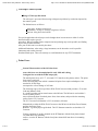
This Manual is intended as an aid in familiarization with the observatory and
telescope, for both those new to it (as an introduction) and for those familiar with
it (as a general overview). More detailed operational/technical manuals are
available for all instruments currently in operation and most operational
components of the facility.
A manual such as this requires continuous updating; large portions of it become
obsolete in a matter of a few years and sometimes a few months. This is done on
a regular basis, and new versions will be released at, we hope, quite frequent
intervals. In order to achieve this, your help will be invaluable. Please email any
contributions, comments or suggestions you may have to the address given
below. Figures can be directly incorporated if they are provided as common
image files or in AutoCAD format.
The CFHT web site contains the latest information regarding availible
instruments, as well as the latest news and other useful information.
Interested astronomers and scheduled observers are invited to consult the
"Welcome to CFHT" document, which covers practical arrangements, travel
conditions, observing runs, the Hale Pohaku facility, and many more logistical
subjects.
Copyright (c) CFHT. All rights reserved.
This page was last modified on: Wed, 05 Nov 2003 21:19:52 GMT
Comments to: "website at cfht.hawaii.edu"
2 of 2
Home, News, Observing, Science,
Images, Outreach, OurUsers
08/07/04 11:20 PM
CFHT Observatory Manual - Site (Sec.2)
http://www.cfht.hawaii.edu/Instruments/ObservatoryManual/CFH...
CFHT Observatory Manual
Section 2 - SITE CHARACTERISTICS
TABLE OF CONTENTS
Weather
Mean minimum temperatures at the summit are around 0 C (summer) and -4 C (winter). Extreme
temperatures hardly ever go lower than -10 C. Daytime temperatures are normally about 10 C in
summer and 3 C in winter. Weather conditions in the Hawaiian Islands are determined largely by
the strong persistent Northeast Pacific Ocean anticyclone, which usually gives rise to easterly
(trade) winds in Hawaii, especially during the summer season. Trade winds give an inversion layer
with an average height of 2000m; air above this inversion tends to be both dry and stable, hence
giving the good astronomical quality usually experienced at the Observatory. At the mesoscale
level, the summit of Mauna Kea is generally intercepting a free flow of air, thus preserving this good
quality. However, high altitude cirrus can be a problem; in some years it has been present about
30% of the time. The mean annual precipitation at the summit of Mauna Kea is ~15 cm, most of
which falls as snow during the winter.
Site Quality
General characteristics include: 80% usable nights (55% photometric, 25% spectroscopic), median precipitable
water
vapor 0.9 mm.
The median seeing (free atmosphere) is ~0.40 arc sec, with a likely systematic variation between winter (0.45)
and
summer (0.35). The 10 percentile is probably of the order of 0.25 arc sec. The summit of Mauna Kea appears to
be in
that respect, the best known site on earth. Observers must be cautioned, however, that seeing characteristics
are often
highly variable, even during the course of a single night.
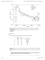
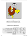
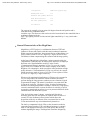
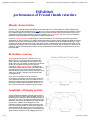
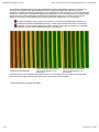
Image Quality
A large sample of CCD images, either at prime or F/8 Cassegrain focus, have allowed good statistical
study of the
image quality with CFHT. Images are at the subarcsec level at least 75% of the time and long-exposure
images with
FWHM better than 0.4 arcsec have been obtained. The figure below shows the evolution of image quality
as
documented by science images taken since the beginning of CFHT operations. Note that the HRCam and
SIS images
have been taken with the instruments’ fast tip/tilt systems, and that the MOS images are badly
under-sampled.
1 of 8
08/07/04 11:20 PM
CFHT Observatory Manual - Site (Sec.2)
http://www.cfht.hawaii.edu/Instruments/ObservatoryManual/CFH...
Median image quality with FOCAM is slightly better than 0.8 arc sec. Optical quality of the telescope,
dome and mirror
seeing, image motion and guiding errors play a substantial role, and the free atmosphere seeing is
usually better as
noted above.
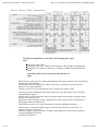
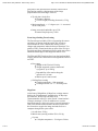
Sky Brightness
Average sky brightness at zenith during dark time is given in the table below.
Color
U
B
V
R
I
J
H
K
Equivalent
( )
0.36
0.44
0.55
0.64
0.79
1.23
1.66
2.22
Brightness
2
Flux
2
2
[mag/(") ]
[phot./cm /s/microns/(") ]
21.6
22.3
21.1
20.3
19.2
14.8
13.4
12.6
1.74x10e-2
1.76x10e-2
3.62x10e-2
5.50x10e-2
1.02x10e-1
2.49
4.20
3.98
Night sky brightness in U increases by a factor of 5 at quarter moon and 65 at full moon. Corresponding
values in V
are 1.3 at quarter and 5 at full moon. These rough estimates are of are, of course, for clear (cirrus-free)
nights.
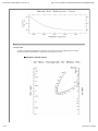
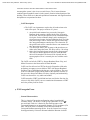
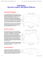
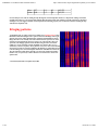
The diagram below shows a typical spectrum of visible night sky emission at Mauna Kea
(reproduced courtesy of Paul Hickson and Alan Stockton).
2 of 8
08/07/04 11:20 PM
CFHT Observatory Manual - Site (Sec.2)
http://www.cfht.hawaii.edu/Instruments/ObservatoryManual/CFH...
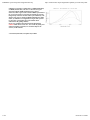
From 1.5 microns to 2.2 microns the spectrum of night sky emission is dominated by OH emission lines;
between 2.2m
and 2.55m H2O lines and thermal continuum are the dominant contributors.
(1) A spectrum from Kitt Peak, by Broadfoot and Kendall, in the near infrared region is included for
reference.
(2) Typical spectra, taken from ESO (Chile) and from UKIRT (Mauna Kea) are included for
reference.
3 of 8
08/07/04 11:20 PM
CFHT Observatory Manual - Site (Sec.2)
http://www.cfht.hawaii.edu/Instruments/ObservatoryManual/CFH...
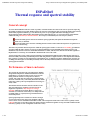
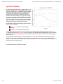
Average background fluxes are quite variable in the infrared. Over a few minutes they typically vary by
1% in J, 2% in H
and 0.3% in K. These figures by T. Gerball, obtained at UKIRT, are highly variable, however, especially
for J and H.
Longward of 2.5 m the background emission is set by thermal radiation from the telescope and from the
atmosphere.
Mean sky emissivity is 0.35 at 20 m and 0.67 at 27 m.
City lighting is relatively small, and quite often completely damped from cloud cover at the 2000-3000 m
level. A county
ordinance has been adopted, which restrict most lights of the Big Island to low-pressure sodium lamps.
For an interesting look at our night light environment at CFHT, see The Light Environment of Mauna
Kea.
Precipitable Water
The summit of Mauna Kea is especially dry and, on clear nights, typical total water content is ~1 mm. It is
thus a good
site for observations in the near to mid-infrared (1 micron to 25 micron).
Wind
Throughout the year, the wind rose is clearly bi-modal; a large percentage of the time winds are either
4 of 8
08/07/04 11:20 PM
CFHT Observatory Manual - Site (Sec.2)
http://www.cfht.hawaii.edu/Instruments/ObservatoryManual/CFH...
easterly or westerly.
50% of the time, wind speed is less than 7 m/s and 84% of the time it is less than 12 m/s. About 5% of
the time, they are
more than 30 m/s and the telescope must be closed. When observing during strong winds it helps to point
only at objects
which are situated roughly leeward. Note that these are average values, and that the percentage of very
high winds is
extremely variable from one period to another.
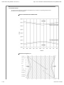
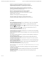
Extinction and Refraction
The mean extinction coefficient and refraction versus wavelength for Mauna Kea are shown below.
Extinction Curve for Mauna Kea
Atmospheric Refraction for Mauna Kea
5 of 8
08/07/04 11:20 PM
CFHT Observatory Manual - Site (Sec.2)
http://www.cfht.hawaii.edu/Instruments/ObservatoryManual/CFH...
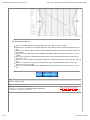
Airmass Values
An airmass nomograph for Mauna Kea is given here. Note that a unit airmass at Mauna Kea (with a mean
barometric pressure of 605 millibars) is equivalent to 0.60 airmass at sea level.
Nomogram to estimate airmass
6 of 8
08/07/04 11:20 PM
CFHT Observatory Manual - Site (Sec.2)
http://www.cfht.hawaii.edu/Instruments/ObservatoryManual/CFH...
Astronomical Calendar
The time of sunset and sunrise at Mauna Kea throughout the year, and the corresponding sidereal time are
provided in the accompanying figures.
Sunrise and Sunset times for Mauna Kea
Siderial time through the year
7 of 8
08/07/04 11:20 PM
CFHT Observatory Manual - Site (Sec.2)
http://www.cfht.hawaii.edu/Instruments/ObservatoryManual/CFH...
Site characteristics references
Bely, P.Y.: Weather and Seeing on Mauna Kea 1987, Publ. Astron. Soc. Pac., 99, 560.
Broadfoot, A.L., Kendall, K.R.: The Airglow Spectrum, 3100-10000 Å Journal of Geoph. Res. Space Phys., 73,
426.
Erasmus, D.A.: Meteorological Conditions Affecting Observing Quality on Mauna Kea 1986, Publ. Astron. Soc.
Pac., 98, 254.
Krisciunas, K.: Atmospheric Extinction and Night-sky Brightness at Mauna Kea 1987, Publ. Astron. Soc. Pac.,
99, 887.
McCord, T.B., Clark, R.N.: Atmospheric Extinction 0.65-2.50 microns Above Mauna Kea 1979, Publ. Astron.
Soc. Pac., 91, 571.
Morrison, D., et al.: Evaluation of Mauna Kea, Hawaii, as an Observatory Site 1973, Publ. Astron. Soc. Pac., 85,
255.
Racine, R., D. Salmon, D. Cowley, and J. Sovka: Mirror, Dome, and Natural Seeing at CFHT 1991, Publ.
Astron. Soc. Pacific, 103, 1020.
Warner, J.W.: Comparative Water Vapor Measurements for Infrared Sites 1977, Publ. Astron. Soc. Pac., 89,
724.
Version 1.0 January, 2003
Copyright (c) CFHT. All rights reserved.
This page was last modified on: Thu, 06 Nov 2003 14:13:30 GMT
Comments to: "website at cfht.hawaii.edu"
8 of 8
Home, News, Observing, Science,
Images, Outreach, OurUsers
08/07/04 11:20 PM
CFHT Observatory Manual - Observatory (Sec.3)
http://www.cfht.hawaii.edu/Instruments/ObservatoryManual/CFH...
CFHT Observatory Manual
Section 3 - THE OBSERVATORY
TABLE OF CONTENTS
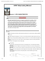
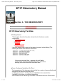
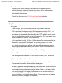
CFHT Observatory Facilities
Building General
These pages show the floor plans of each level in the dome. (under
construction)
1st (Ground) Floor
2nd Floor
3rd Floor
4th Floor
5th (Dome) Floor
Live video images can be received at various locations in the building. The
following are some useful channel allocations.
Channel 03:
Channel 06:
Channel 07:
Channel 08:
Channel 09:
Channel 10:
TV guiding camera (Cass and Coude)
Dome slit low light camera
West view of inside dome
Main entrance door
East view of inside dome
South view of telescope
Visitors are reminded that, in keeping with staff safety
requirements, hard hats should be worn at all times when
working in the dome area and main hatch area.
Dome Cooling and Ventilation (5th Floor)
The temperature of the dome area is controlled via a series of sensors distributed
throughout the dome and coupled to the
building glycol system. Cooling coils are imbedded in the concrete floor.
Ventilation of the dome is controlled primarily by
the motorized louvers at the top and bottom of the dome structure. These vents
1 of 10
08/07/04 11:21 PM
CFHT Observatory Manual - Observatory (Sec.3)
http://www.cfht.hawaii.edu/Instruments/ObservatoryManual/CFH...
are normally left open to allow air to flow
between the skins of the dome and closed when weather conditions require
sealing off the dome. Controls for these louvers
are located on the mezzanine catwalk, inside the dome.
In addition to the dome skin louvers, there are two fan units which can be
controlled with a timer or switched on and off manually.
These units are also fitted with glycol cooling coils and capable of delivering
chilled air to the dome area. The units are located
on the N.E. portion of the dome, (directly over the freight elevator) and also on
the S.E. portion of the dome, (directly over the
visitors gallery).
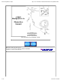
Dome Shutter and Windscreen (5th Floor)
The dome shutter is an "up and over" type shutter, consisting of 12 hinged
sections and driven by eight motors on a rack and
pinion drive system.
The control of the shutter can only be done from the dome catwalk.
The windscreen is a cable driven device consisting of a series of steel partitions
which store themselves in concertina fashion
at the base of the closed shutter. It is a gravity-activated lowering device and the
sections tend to hang up in high wind conditions.
Two slack cables have been recently fitted which prevent the down motion of the
windscreen in that case. When it happens, the
dome has to be rotated to take the windscreen away from the wind and the cable
driven up before attempting to cover the
windscreen. Like the shutter, the windscreen is controlled from the dome catwalk.
Seeing Conversion Measures (5th Floor)
Since a 1 C air temperature differential at the level of the primary mirror gives a
seeing degradation of about 0.5 arcsec, strict
control of the telescope thermal environment is essential. This is done chiefly by
maintaining the dome floor temperature, and the
temperature of the oil used in the telescope’s hydrostatic bearings near the mean
midnight outside air temperature of 0 C. This
cooling system is occasionally shut down,in particular during summit snow
storms. After inclement weather, observers should
confirm with the Observing Assistant operating the telescope that the chilling
system has been restarted.
Power dissipation in the dome is generally kept low. In particular, the sodium
vapor flood lamps on the 5th floor are turned off
when not needed. Similarly, all doors opening onto the observing floor, including
those leading to the elevator, should be closed
at all times. Generally, the dome slit is closed during the day, but may be opened
on occasion for engineering purposes.
Observers bringing visiting equipment can help reduce power dissipation near
the telescope by using the AC/DC power sources
provided at the various foci in lieu of instrument power supplies.
2 of 10
08/07/04 11:21 PM
CFHT Observatory Manual - Observatory (Sec.3)
http://www.cfht.hawaii.edu/Instruments/ObservatoryManual/CFH...
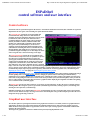
Control/Observing Room (4th Floor)
The telescope control/observing room is located on the fourth floor, directly to the
left upon exiting the elevator. A large console
contains the controls and computers necessary for controlling the telescope
(Operator’s section at right) and most CFHT
instrument sessions (Observer’s section at left). The guiding TV’s can be viewed
by both the Observer and the Observing Assistant.
A stereo audio system is also incorporated, and you can bring your favorite audio
tape or CD. Copies of a variety of useful
handbooks can also be found such as the SAO Star Catalog, The Astronomical
Almanac and the Observer’s Handbook.
Auxiliary Observing Room (4th Floor)
The room is located beyond the control/observing room, and adjacent to the
computer room on the fourth floor. It contains 19 inch
racks for auxiliary equipment, general-purpose instrumentation cabling
connected to the two foci and electronic crates. Many visitor instruments are
also operated from here. An observer’s console provides TV guiding monitoring,
an intercom equipment for
communication with the Observing Assistant, and workstations connected to the
CFHT local area network.
Remote Observering Facilities (Waimea)
TeleVideo communications are availible for remote observing from the CFHT
Headquarters, and observations may be done by
observers running identical observing sessions from the comfort of the Waimea
office. Observers interested in Remote Observing
should contact their support astronomer.
Instrument Preparation Labs (2nd and 3rd Floors)
There are two laboratories available on the second floor for the set-up and
testing of instruments. Room 209 (IP1) is best suited for
vacuum and cryogenics work. A pumping station comprising a turbomolecular
pump and a pair of Vacsorb pumps is available for
evacuating cryostats. The room is also equipped with an Edwards helium leak
detector.
For pumping on cryogens, there are two systems each using a Sargeant-Welch
Model 1397 mechanical pump (500 liters/minute).
These systems are also connected by plastic tubing to the Infrared and Optics
Lab (Room 209A) and to a manifold at the
Cassegrain focus of the telescope. The two pumps can be used separately or in
parallel.
IP1 also contains a work bench and various cryogenic accessories such as small
dewars and a helium transfer tube. The standard
vacuum hardware at CFHT is Klamp Flange or Alcatel KF 10 or 16.
The second instrument preparation room (IP2) comprises the combined area of
3 of 10
08/07/04 11:21 PM
CFHT Observatory Manual - Observatory (Sec.3)
http://www.cfht.hawaii.edu/Instruments/ObservatoryManual/CFH...
Rooms 205 and 206. A CAMAC crate which can
be connected to the PICA computer is available here, as well as a desk, cabinets
and several tables.
There is a small collection of tools and test equipment (multimeter, oscilloscope,
signal generator) available for visitor use.
Observers bringing their own instrument should not rely solely on this, however,
but should bring with them any spare parts, tools
or test equipment they may need.
Clean Room Facilities (3rd Floor)
CFHT maintains a clean room for detector repair/maintenence at the summit.
LAMA Room (4th Floor)
The YAg LAser MAchine is located on the fourth floor adjacent to the Auxiliary
Observing Room. It is connected to the local area
computing network. Observers use this facility to cut masks for multi-object
spectrography (MOS/OSIS).
CCD Lab (3rd Floor)
The CCD Lab is used primarily for storage and preparation of the MegaCam.
Infrared and Optics Laboratory Facilities (2nd and 3rd Floors)(Waimea
Headquarters)
Lab space is available on the 2nd and 3rd floors.
A modest optics lab facilities and clean room are availible at the Waimea
Headquarters facility. Access to these labs should be
prearranged with your Support Astronomer.
Mechanical Shop (1st Floor)
A small mechanical shop contains a bandsaw, cut-off saw, vise, shear, drill
press, grinder, lathe, milling machine, welding
equipment, and an assortment of hand tools. This equipment is not intended for
instrument fabrication. It is for emergency
repairs only and is not available to Observers.
Electronics Shops and Detector Labs (2nd and 3rd Floors)
A modestly equipped electronics lab is located in the building and is used for
servicing the telescope and CFHT instrumentation.
This laboratory is for staff use and is not available to Observers. Observers
should use the work station located in the
instrumentation preparation room.
A CCD lab is located in Room 319. It is used by the staff for preparation of the
CCD runs.
Living Facilities (3rd and 4th Floors)
A heated lounge on the fourth floor ("Café du Mont Blanc") is provided with
4 of 10
08/07/04 11:21 PM
CFHT Observatory Manual - Observatory (Sec.3)
http://www.cfht.hawaii.edu/Instruments/ObservatoryManual/CFH...
comfortable furniture, and a kitchenette. This facility
is for use by observers, staff, and guests for short rest periods during the day or
night.
Observers are requested to leave the kitchen in good order, especially during
weekends when no cleaning staff is on duty.
On the third floor there is one small bedroom and a washroom for use by
personnel during day or night. These bedrooms are
humidified but not pressurized. Individuals should remember that sleeping at
4200 m is very difficult, and not always
recommended, unless one is fully acclimatized.
Weather Station
A weather station is mounted on a tower adjacent to the dome. Readouts of the
weather station instruments are found directly
above the TV monitors at the telescope control console. A chart recorder view is
also availible, on the Telescope Status monitor
of the Telescope Control System (TCS). The instrument levels are shown in
colored traces. Several FITS keywords of
potentially useful weather data are added to the FITS header of each image file.
Compressed Air
Seven-bar filtered and dried compressed air is available for use by Observers at
the following locations:
instrument labs
upper coudé slit room
telescope Cassegrain focus
optics labs (including the LAMA room)
Glycol Cooling System (this section needs updating and inclusion of the
MegaPrime cooling system)
Because of the expense of trucked water, a recirculating cooling system has
been installed for all cooling purposes by
observers.
The cooling points are equipped with a valved supply line and a drain and are
installed in the following locations:
coudé rooms and coudé auxiliary rooms
infrared laboratory
instrumentation preparation room
Coolant characteristics are as follows:
maximum flow: 40 liters/minute
maximum pressure: 5 bars
incoming temperature: 10oC (adjustable)
Dry Nitrogen
5 of 10
08/07/04 11:21 PM
CFHT Observatory Manual - Observatory (Sec.3)
http://www.cfht.hawaii.edu/Instruments/ObservatoryManual/CFH...
Dry nitrogen outlets are available at telescope foci. Dry nitrogen is also available
in cylinder form, complete with gauges, on a
suitable trolley.
Electrical Power
Electrical power at the summit is provided by the Island-wide HELCO (Hawaii
Electric Light Company) grid which supply 480 volts,
3 phase, 60 Hz. Every room within the observatory is equipped with 110 volts 15
amp, 1 phase circuits. In addition, there are
special purpose 40 amp and 15 amp, 208 volt, 3 phase plugs available on the
observation floor, coudé rooms, coudé observation
rooms and LAMA room. The regulation is generally plus or minus 5% in voltage
and plus or minus 1 Hz.
Protected power supplies... To take care of fluctuating power, a Uninterrupted
Power Supply system has been installed for certain
systems.
All plugs in the building conform to American standards. French standard plug
adapters and 110/220 volts transformers up to 50 kvA
are available.
Special power equipment, consisting of portable electric supply boxes, is
available for the following services:
a) 220 volt, 1 phase, 60 Hz with French plugs.
b) 220 volt, 50 Hz, 1 phase regulated power plus or minus 2 percent, with
French plugs.
Building Communication Systems
The CFHT dome has a general purpose intercom system. 14 stations and 25
speakers are located throughout the dome, allowing
for easy paging.
To make a general announcement, press "Page" at any telephone station. After
the tone burst, speak into the transceiver, then
hang up.
Apart from the intercom, there is also an independent communication system
called Clear-Com. This consists of a network of
8 remote stations controlled from the Control Room console and is very useful for
talking to the O.A. on a permanent basis, using
the gooseneck microphone at the astronomers’ console at coudé focus, from the
prime focus cage or from the auxiliary observing
room. Other locations are: the upper coudé room, the slit room, the Cassegrain
environment, the prime focus cage, etc. If the
voice level is too low, slightly turn up the Headset/Speaker volume knob on the
remote station KBIII (the recessed steel base at
the right side of the observer’s console front panel). Be careful; with the live
microphone it is easy to get loud feedback by turning
the speaker up too much.
Walkie-talkies are also available, which allow permanent communication from
6 of 10
08/07/04 11:21 PM
CFHT Observatory Manual - Observatory (Sec.3)
http://www.cfht.hawaii.edu/Instruments/ObservatoryManual/CFH...
anywhere in the building.
More information on these dome audio-systems can be received by contacting
staff astronomers, telescope operators and other
technical staff members at the observatory.
Loaned Equipment
On special occasions, certain instruments or apparatus may be loaned to
Observers who have experienced difficulty with their own
equipment. Observers should not, however, rely on the availability of any
apparatus on loan unless prior explicit arrangements have
been made in writing with the Corporation. This applies, for example, to such
items as vacuum pumps, oscilloscopes, amplifiers,
cryogenic transfer tubes, etc.
Telephone
Observers may use the telephone at the summit. It is very reliable, but
occasionally may be out of operation for a few days at a
time during severe storms. Long-distance calls should be made collect, by credit
card, or billed to a home phone number.
In cases when it is impossible to do this, Observers may still make calls which
will, in turn, be billed to them.
There also is a FAX machine (No. (808) 935-4511).
Photocopier
A small photocopier is available in the staff office (4th Floor). It may be used for a
limited amount of copying.
Safety Equipment
Hard hats are required in the dome and hatch areas. They are located on the 4th
and 5th floor.
In case of minor injury, first aid supplies can be found in the first aid room on the
ground floor and at various other locations
throughout the building.
For emergency escape (e.g. in case of fire or trapping) escape devices have
been installed on the 4th and 5th floor mezzanine
exit doors, as well as in the crane cab inside the dome.
Waimea Base Facilities
General Description
The CFHT Base Facility is located in Waimea (Postal Address Reference:
KAMUELA 96743) on the Island of Hawaii. The building
is situated on the north side of Highway 190 about 300 m west of the intersection
7 of 10
08/07/04 11:21 PM
CFHT Observatory Manual - Observatory (Sec.3)
http://www.cfht.hawaii.edu/Instruments/ObservatoryManual/CFH...
of Highways 190 and 19.
The town of Waimea and surrounding region have a population of about 15,000.
The principal economic activities are cattle
ranching, diversified agriculture, and service industries. The Parker ranch is by
far the largest of the cattle ranches
(250,000 acres or 100,000 hectares). In Waimea, there is a post office, medical
center, several banks, several shopping centers,
and a theater.
The Base Facility is the principal work place for most of the Corporation’s staff
members. In addition to offices, there is a data
reduction facility, a library, optics and electronics labs, a technical design (CAD)
lab, machine shop, and vehicle maintenance facility.
Guest observers are strongly encouraged to spend a day or so in Waimea before
or after their run. They are most welcome to
present some of their current work in an ~45 minute long, relaxed seminar. An
overhead viewer and LCD projector are available
at CFHT.
Data Processing Facility
The Data Reduction Facility is available to meet the needs of the visiting
astronomer in the areas of data backup, data retrieval,
and preprocessing. The primary purpose of the facility is to allow the visiting
astronomer to preprocess data from CFHT detectors
to a degree that the astronomer is able to start scientific analysis and/or to
remove a record of their observations to their home
institution.
Tape Copying
Observers have the option of taking their raw telescope data offsite or
having them concatenated to reduce the amount of
media. Observers can also have copies made of their raw data for
co-investigators etc. Observers should plan on spending
half a day in Waimea at the end of their run if they require data
copying/concatenation.
Data Retrieval
CFHT now maintains a permanent record of all observations taken with the
data acquisition system. This record is made in
real time and recorded on optical disk. When full the optical disks are
shipped to the Canadian Astronomical Data Centre
(CADC) in Victoria, BC, Canada for eventual inclusion in an Archive of
CFHT data, through which non-proprietary data is
made available to interested researchers. In the event of inadvertent loss of
any FITS files, the Principal Investigator can
arrange to have images recovered from the Canadian Astronomy Data
Centre. Due to the technologies involved it is not
always possible to recover FITS files immediately.
8 of 10
08/07/04 11:21 PM
CFHT Observatory Manual - Observatory (Sec.3)
http://www.cfht.hawaii.edu/Instruments/ObservatoryManual/CFH...
Library
The library has modest holdings of astronomical and engineering books,
scientific and engineering periodicals, and catalogues. In
addition, the library houses the Palomar Sky survey, current instrumentation
manuals, reports, and technical information from
other leading observatories.
Consult the Librarian or the CFHT Library Home Page for details.
Supplies
Cryogens
Liquid nitrogen, liquid helium and dry ice can be provided to observers.
LN2 is purchased in self-pressurizing 160-liter dewars (owned by CFHT). It is
produced in Honolulu and shipped by barge to Hilo,
from where it is transported to the observatory by CFHT staff. We usually decant
the LN2 into self-pressurizing 25-liter dewars for
ease of use. No charge is made for the LN2 required for CFHT instruments or for
similar small amounts used by visitor instruments.
LHe is purchased in either 100-liter or 60-liter dewars. Our experience is that the
dewars are on average 60% full when they reach
the summit. Normal boiloff in storage is 1-2 liters/day. Although LHe is now
produced in Honolulu, it is still occasionally necessary for
us to obtain our supply from California. LHe is considered hazardous cargo by
many freight companies and usually must travel by surface--hence the need for
six weeks’ notice.
Dry ice must be obtained from Honolulu, in 50 pound (23 kg) increments.
Magnetic Tapes
Data storage media is available for Guest Observers using CFHT instruments.
Cold-weather Gear and Survival Kit
As mentioned previously, nighttime temperatures can be as low as -6 C.
Furthermore it is our policy to keep ambient temperature
below +15 C in most rooms in the telescope building.
In order to guarantee themselves adequate cold-weather gear, Observers should
provide it for themselves, although down-filled
trousers, and hooded parkas can be rented at Hale Pohaku. In all cases, leather
or thermal boots should be brought by Observers,
even during summer. Low oxygen concentration and the resultant lowering of
metabolism at 4200 meters make the temperature
seem colder than it would be at a lower altitude. Comfort items such as, lip balm
and lotion for dry skin, analgesic for headaches
9 of 10
08/07/04 11:21 PM
CFHT Observatory Manual - Observatory (Sec.3)
http://www.cfht.hawaii.edu/Instruments/ObservatoryManual/CFH...
(aspirin or acetaminophen) are also recommended.
Flashlights
Visitor’s should bring their own flashlights and batteries.
Version 1.0 January, 2003
Copyright (c) CFHT. All rights reserved.
This page was last modified on: Fri, 07 Nov 2003 06:15:46 GMT
Comments to: "website at cfht.hawaii.edu"
10 of 10
Home, News, Observing, Science,
Images, Outreach, OurUsers
08/07/04 11:21 PM
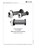
CFHT_ObservatoryManual_Floor1
http://www.cfht.hawaii.edu/Instruments/ObservatoryManual/CFH...
1st Floor
Description:
1. Lobby* - (Visitor Stairway*, Visitor Elevator*, First Aid Room, Rest Rooms)
2. Foyer - Main Entrance (South Door)
3. Personnel Check In/Out Area (Name Tag Board, Time Clock, Staff Elevator, Staff Stairway)
4. Mechanical Room (Dome Hydraulics, Glychol Chiller System, Telescope Hydraulics, Back Up Generator, Building Water
System Control)
5. Machine Shop
6. Frieght Elevator
7. Weld Shop
8. Hatchway
9. Aluminizing Room
* - These facilities no longer used for visitors
1 of 2
08/07/04 11:22 PM
CFHT_ObservatoryManual_Floor1
Copyright (c) CFHT. All rights reserved.
This page was last modified on: Sun, 02 Nov 2003 20:33:04 GMT
Comments to: "website at cfht.hawaii.edu"
2 of 2
http://www.cfht.hawaii.edu/Instruments/ObservatoryManual/CFH...
Home, News, Observing, Science,
Images, Outreach, OurUsers
08/07/04 11:22 PM
CFHT_ObservatoryManual_Floor2
http://www.cfht.hawaii.edu/Instruments/ObservatoryManual/CFH...
2nd Floor
Description:
1.
Copyright (c) CFHT. All rights reserved.
This page was last modified on: Sun, 02 Nov 2003 20:33:06 GMT
Comments to: "website at cfht.hawaii.edu"
1 of 1
Home, News, Observing, Science,
Images, Outreach, OurUsers
08/07/04 11:22 PM
CFHT_ObservatoryManual_Floor3
http://www.cfht.hawaii.edu/Instruments/ObservatoryManual/CFH...
3rd Floor
Description:
1.
Copyright (c) CFHT. All rights reserved.
This page was last modified on: Sun, 02 Nov 2003 20:33:08 GMT
Comments to: "website at cfht.hawaii.edu"
1 of 1
Home, News, Observing, Science,
Images, Outreach, OurUsers
08/07/04 11:22 PM
CFHT_ObservatoryManual_Floor4
http://www.cfht.hawaii.edu/Instruments/ObservatoryManual/CFH...
4th Floor
Description:
1.
Copyright (c) CFHT. All rights reserved.
This page was last modified on: Sun, 02 Nov 2003 20:33:10 GMT
Comments to: "website at cfht.hawaii.edu"
1 of 1
Home, News, Observing, Science,
Images, Outreach, OurUsers
08/07/04 11:23 PM
CFHT_ObservatoryManual_Floor5
http://www.cfht.hawaii.edu/Instruments/ObservatoryManual/CFH...
5th Floor
Description:
1.
Copyright (c) CFHT. All rights reserved.
This page was last modified on: Sun, 02 Nov 2003 20:33:14 GMT
Comments to: "website at cfht.hawaii.edu"
1 of 1
Home, News, Observing, Science,
Images, Outreach, OurUsers
08/07/04 11:23 PM
CFHT Observatory Manual - Observatory (Sec.4)
http://www.cfht.hawaii.edu/Instruments/ObservatoryManual/CFH...
CFHT Observatory Manual
Section 4 - THE TELESCOPE
TABLE OF CONTENTS
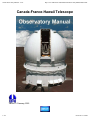
General Features
The CFH telescope is of the yoke type similar to the Palomar 5 meter telescope. It is a classical
Prime Focus/Cassegrain
combination. The primary mirror has a usable diameter of 3.58 m and has a parabolic figure. The
primary and secondary
mirrors are made of the low expansion coefficient glass-ceramic "Cer-Vit" and are thus practically
immune to thermal distortion.
1 of 17
08/07/04 11:26 PM
CFHT Observatory Manual - Observatory (Sec.4)
http://www.cfht.hawaii.edu/Instruments/ObservatoryManual/CFH...
For computations of light throughput, it is interesting to note that a 20th
magnitude object gives at 5500 Å flux of 1 photon/second/Å. This
number, of course, has to be multiplied by the transmission of the
system:
atmosphere + telescope (including central obscuration) + instrument +
detector.
The main optical characteristics at the different focii are
summarized in the table below:
2 of 17
08/07/04 11:26 PM
CFHT Observatory Manual - Observatory (Sec.4)
http://www.cfht.hawaii.edu/Instruments/ObservatoryManual/CFH...
The optical configurations are altered by interchanging three upper
ends:
Prime Focus and Coudé
Cassegrain f/8 (CAFE - fiber fed Coudé operates in the Cassegrain configuration)
Cassegrain f/35 (infrared) - This focus is no longer available (Decommissioned in
2000)
Interchange takes at least 3 hours and cannot be done at
night.
While observing, the dome slit is aligned automatically with respect to the telescope. The shutter is
normally fully opened during
the night but can be closed partially to reduce wind loads. A windscreen can also be raised.
Observers are warned that dome
rotation is quite slow, with a maximum speed of 45 degrees per minute of time.
The telescope area is maintained at the proper temperature by a chilled floor system. The floor
cooling normally operates
24 hours a day. It will be shut down, however, during summit storms and takes roughly a day to
stabilize once turned back on.
Experience has shown that the seeing is degraded if the floor cooling is shut off. Alternatively,
during high humidity conditions, the
floor cooling can cause severe icing, detrimental to electronic equipment and optics.
The telescope is controlled during the night by the Observing Assistant (or OA) only. This
includes all aspects of telescope
opertation, support systems (computer, electronic, and mechanical), and telescope orientation,
slewing and guiding on the field
requested by the observer.
3 of 17
08/07/04 11:26 PM
CFHT Observatory Manual - Observatory (Sec.4)
http://www.cfht.hawaii.edu/Instruments/ObservatoryManual/CFH...
Telescope Control System
Range of Telescope Movement
The telescope is prevented from moving to dangerous positions by restrictions imposed by
the control system.
The limitations are as follows:
hour angle: 6h 00m east and west
declination: -58 deg to +99 deg (9 deg below N Pole)
horizon: 8 deg above the horizon
For special applications the telescope can be brought down in some areas to within 3o of the
horizon but this requires special
procedures. When exceeding limits, computer-assisted pointing may not be possible, and finding
objects may be rather difficult.
Also, part of the beam is occulted by the dome.
Additional limitations, when using a large instrument, can be inserted to avoid a possible
instrument crash on the telescope
South and North piers. There are currently no such limitations for any CFHT instrument.
Prime Focus
General Characteristics of the f/4 Prime focus
(note: this focus was decommissioned in early 2003 and is being
redesigned for use with the WIRCam project)
The naked prime focus, at f/3.77, is located 13533 mm above the primary mirror. The prime
focus cage is equipped
with a focussing stage onto which is mounted all prime focus optics and adaptors. One
encoder bit for this stage
corresponds to a focus change of .022 mm.
The focussing stage will accept either a Wide Field Corrector which provides a 55 arc min
(240 mm) diameter field,
or a coudé secondary mirror turret known as the M2 unit. The M2 unit is used with the 3
coudé secondary mirror,
removed from the beam for naked prime focus observations, and provides the mounting
surface for the UV Corrector.
The UV Corrector field diameter is 22.5 arc minutes (100 mm).
Mounted above either the Wide Field Corrector or the M2 unit is the Prime Focus Rotator,
and then the Prime Focus
Bonnette - a general purpose guide head. The P.F. Bonnette cannot be used with the UV
Corrector.
Visiting equipment is usually mounted on the PF Bonnette with the focal plane situated
120.0 mm above the mounting
surface, or on the PF Rotator, with the focal plane situated 450 mm above its mounting
surface.
4 of 17
08/07/04 11:26 PM
CFHT Observatory Manual - Observatory (Sec.4)
http://www.cfht.hawaii.edu/Instruments/ObservatoryManual/CFH...
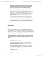
Prime Focus optical configuration is shown below. Image quality of the primary mirror at
the geometrical focus, according
to optical shop tests, is 0.2 arcsec FWHM.
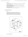
Prime Focus Cage
The internal dimensions and a schematic layout of the prime focus cage are available. The
cage can carry a maximum
payload of 400 kg including the Observer, instrumentation, and all auxiliary equipment.
Heavy visitor equipment will be
weighed by CFHT before being installed in the cage. Installation will be prohibited if the
overall limit is exceeded.
The following table gives the allowed additional weight (including the Observer) for
standard pieces of equipment.
5 of 17
08/07/04 11:26 PM
CFHT Observatory Manual - Observatory (Sec.4)
http://www.cfht.hawaii.edu/Instruments/ObservatoryManual/CFH...
Configuration
Additional payload (kg)
Naked prime focus
270
Naked PF with guiding head 162
Wide Field Corrector
274
WFC with guiding head
166
UV Corrector
240
The cage can be rotated by plus or minus 190 degrees from the mid position and is
controlled from a pushbutton station
inside the cage. The Observers chair can be raised or lowered and is also controlled from a
pushbutton station inside the
cage. Cage lighting consists of white and red lights controlled by a 3-way switch and a
dimmer.
General Characteristics of the MegaPrime
MegaPrime, a CFHT project, is a collaboration between CFHT and
institutes in France and Canada, with three major industrial contractors.
Within a myriad of capabilities, the principal mission of MegaPrime is to
offer scientists a field of view of 1 degree by 1 degree, the size of four
Full Moons, without compromising the resolution and the image quality.
At the heart of MegaPrime is MegaCam, a unique camera built by the
"Département d’Astrophysique, de Physique des Particules, de Physique
Nucléaire et de l’Instrumentation Associée" at the French
"Commissariat à l’Energie Atomique" (CEA). To cover the 1 square
degree field, CFHT ordered 40 CCDs from a company in the United
Kingdom, e2v technologies, which specializes in the production of high
quality detectors. CEA mounted these CCDs very precisely in a mosaic
which central area, made of 4 rows of 9 CCDs, covers a square of 25cm
by 25cm, or 1 degree by 1 degree on the sky.
When used for astronomical applications, CCDs have to be operated at
very low temperatures to reduce the amount of thermic noise they
generate during the long exposures (minutes to tens of minutes) typical
of astronomical images. The mosaic is installed in a cryostat where the
CCDs can be cooled to -120 degree Celsius. In order to minimize the
thermal losses through temperature exchanges with the air, a high quality
vacuum is maintained in the cryostat; the mosaic is cooled by a special
cryogenics system based on pressure waves in pressurized helium, which
extract the heat from inside the cryostat.
CEA also built the camera’s shutter, a rotating half-disk able to
uniformly open and close the camera for exposure times as short as 1
second; CEA also fashioned a filter jukebox which allows the
observation of the sky in different colors, an essential device as the
CCDs cannot disclose any color information by themselves.
The last key components built by CEA are the electronics needed to
extract the image from the CCDs: each MegaCam image is currently
made of 340 megapixels that have to be read quickly and carefully,
without degrading the image. The MegaCam electronics designed by
6 of 17
08/07/04 11:26 PM
CFHT Observatory Manual - Observatory (Sec.4)
http://www.cfht.hawaii.edu/Instruments/ObservatoryManual/CFH...
CEA can read the image in less than 35 seconds while maintaining a
very low readout noise - this is, in fact, the shortest readout time ever
achieved on a mosaic operated at CFHT!
As it was not possible to accommodate a 1 square degree field of view
with the old cage of the early days (still in use for CFH12K), a new,
upper end of the telescope had to be constructed. Designed at CFHT in
collaboration with the "Division technique" of the French "Institut
National des Sciences de l’Univers", it was built by a Californian
company, L&F Industries, now a division of Erie Press Systems. 13
meters above the main mirror of the telescope, this upper end offers a
platform ready to host the equipment needed to give to the camera a nice
view of the sky.
The parabolic main mirror of the telescope does not produce, alone, a
good image of the whole field of view; a wide field corrector (WFC) is
installed in front of the camera. With four lenses 50 to 80 cm in
diameter, in a structure two meters long for 660 kg, the WFC is an
amazing piece of optics designed at the Herzberg Institute for
Astrophysics (Victoria, Canada) and built in France by
SAGEM/REOSC. The resultant pixel size is slightly less than 0.2
arc-seconds: a good resolution giving a reasonable sampling of the
images even with good seeing (images of 0.5" were already observed
several times). To complement the corrector, 5 filters were also
fabricated by SAGEM. They follow relatively closely the Sloan Digital
Sky Survey filter set, but for the blue filter, which makes good use of the
superior transparency of the Mauna Kea sky and the UV enhanced WFC
glass.
To accommodate the changes in focal length of the telescope with
temperature, and the focus position changes induced by the various
filters, the camera must be able to move along the optical axis of the
telescope. The focus stage assembly (FSA) accommodates this motion,
supporting the camera and its shutter on a motorized stage bolted on top
of the upper end platform. In order to follow the apparent motion of the
sky due to the Earth’s rotation, two small cameras fix on stars outside of
the field of view, providing automatic guidance of the telescope and
measurements of the focal changes.
The guiding cameras (’guiders’) are installed underneath the FSA, and
like the FSA, were designed and built at HIA. To compensate for
telescope oscillations due to windshakes or telescope tracking anomalies,
an Image Stabilizing Unit (ISU) made of a tip/tilt plate is attached to the
beam on top of the wide field corrector. Designed at "Observatoire de
Paris", the ISU is servo-controlled through the guiders’ signals.
The integration and overall control of MegaPrime, and all the utilities helium lines, glycol hoses to eliminate all the heat sources on top of the
telescope, electronics box housings, hundreds of yards of cables or optics
fibers - and the development of the observing environment specific to
MegaPrime, have been CFHT’s work.
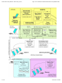
The various components of MegaPrime
Overall weight added to the telescope: 11,000 kg
Weight to be lifted up and down when the instrument
is installed/removed: 5700 kg
Observing runs: 15 to 18 days periods centered on the
7 of 17
08/07/04 11:26 PM
CFHT Observatory Manual - Observatory (Sec.4)
http://www.cfht.hawaii.edu/Instruments/ObservatoryManual/CFH...
New Moon
Upper End
The new prime focus upper end (PFUE) has been designed
at CFHT with the help of INSU-Division Technique: a new
base ring, a new set of spiders, and a prime focus base
which will receive all the other components of MegaPrime.
The PFUE has been built on the West Coast of the USA by
L&F Ind.
In addition to its basic structure, the PFUE provides a
temperature controlled environment for MegaCam and its
readout electronics. A temperature controlled enclosure for
the electronics of MegaPrime is installed on the telescope
"caisson central".
Total weight of the structure itself: 3000 kg
Base ring: 2400 kg
Spiders: 1100 kg
Prime Focuse Environment base: 500kg
With all the Megaprime equipment: 5700 kg
Overall height from the base ring to the top of the
cover: 6 m
Wide Field Corrector
The parabolic main mirror of the telescope does not
produce, alone, a good image of the whole field of view; a
Wide Field Corrector (WFC) is installed in front of the
camera. The WFC has been designed at HIA
(Victoria, Canada). The lenses have been fabricated by
SAGEM/REOSC, which also built the mechanical structure
of the WFC and coated the lenses.
Total weight: 660 kg
Overall height: 1.9 m
Four spherical lenses in BSL7-Y (enhanced UV
transparency glass)
Lens diameter:
First lens: 81 cm
All others: between 50 and 56 cm
Image quality: designed to achieve better than 0.3"
diameter at 80% encircled energy from u to z on most
of the field.
Image Stabilizing Unit
The Image Stabilizing Unit (ISU) has been designed and
built at Observatoire de Paris. It is used to produce small
image position correction on the focal plane of MegaCam: a
8 of 17
08/07/04 11:26 PM
CFHT Observatory Manual - Observatory (Sec.4)
http://www.cfht.hawaii.edu/Instruments/ObservatoryManual/CFH...
glass plate in the optical beam in front the camera can be
tilted and its produces a displacement of the image
proportional to the small angle of the tilt.
Tip-tilt plate: fused silica
Diameter: 480 mm
Overall weight (including electronics): 55 kg
Motion amplitude: +/- 1.2 degrees (or +/- 1 arcsecond
on the focal plane)
Image correction bandwidth: up to 5 Hz
Internal loop frequency: 50 Hz
Focus Stage/Guiding Focus Sensing
The Focus Stage Assembly (FSA) is supporting the camera
and allows its motion along the optical axis in order to
accommodate the focus variation due mainly to filter
changes and temperature induced telescope dilatation. Two
guiders (GFSU) located under the top plate of the FSA give
a position and focus information from two guide stars on the
North and South edges of the MegaCam field of view.
The FSA and GFSU hardware have been designed and built
at HIA, while the the control has been designed and realized
at CFHT.
Focus stage
Weight of the FSA itself: 260 kg
Weight supported (camera, shutter and
cryogenics): up to 250 kg
Repeatability of the motion along the
optical axis: 0.01 mm
Motion speed: 1mm/second
Guiding/focus sensing
Limiting magnitude: ~15th magnitude
Guiding field area: 20’ x 7’ for each guider
MegaCam
At the heart of MegaPrime is MegaCam, a unique camera
built by the "Département d’Astrophysique, de Physique
des Particules, de Physique Nucléaire et de
l’Instrumentation Associée" at the French "Commissariat à
l’Energie Atomique" (CEA). In addition to a cryostat
housing the mosaic, and its criogenics system to maintain it
cold, CEA built the camera shutter, the filter jukebox and
the electonics to acquire the image and and send it to a
computer through fiber optics cables.
Overall mass: 350 kg
Mobile mass (moving with the FSA): 230 kg
Cryostat
Cold plate temperature: -130 degrees Celsius
9 of 17
08/07/04 11:26 PM
CFHT Observatory Manual - Observatory (Sec.4)
http://www.cfht.hawaii.edu/Instruments/ObservatoryManual/CFH...
Readout electronics
Readout time: 30s
Readout noise: less than 5 electrons
Shutter
Type: Half rotating disk
Diameter: 1 m
Minimum exposure time: 1 second
Filter jukebox
Number of filters: 8
Filter change time (in any position of the
telescope): 2 mn
CCDs
Charge Coupled Devices (CCDs) are the detector of choice
in astronomy for observations in visible light. Appeared in
the early eighties, they have since replaced the photographic
plates or films used in astronomy for more than a century.
The CCDs used for MegaPrime have been built by e2v
technologies.
CCD type: CCD42-90
Number of CCDs: 40
Number of CCDs currently used: 36 (a square of 4
rows of 9 CCDs)
CCD size: 2048 x 4612 pixels
Pixel size: 13.5 micrometers
Pixel scale: 0.185 arsecond/pixel
Image size (whole mosaic): 378 Megapixels
Image size (current): 340 Megapixels
Operating temperature: -120 degrees Celsius
Coudé Focus
The CFHT coudé spectrograph, commonly referred to as Gecko, provides
spectroscopists with a spectral resolving power R up to 120,000 from the atmospheric
cutoff near 3000Å to 1µm for CCD’s with up to 4400 13.5µm pixels. Unlike most
echelle spectrographs, Gecko has been optimized for use with a single spectral order
(between 5 and 18) from the 316 groove/mm echellette mosaic. Order sorting is
achieved with interference filters or by one of three variable grisms. An image slicer
is used to optimize the throughput of the instrument. To minimize traffic into and out
of the inner coudé room, the entire spectrograph can be operated remotely from the
control room.
Since July 2000, CAFE, the CAssegrain Fiber Environment, replaces the red coudé
mirror train with optical fibers. CAFE consists of an optical bench mounted to a port
on the Cassegrain Bonnette, two fiber optic cables and a Bowen-Wallraven slicer for
injecting the beam into the Gecko Spectrograph. A "fiber agitator" (which agitates the
optical fiber with an amplitude of 1 mm and a frequency of 30 Hz) has been installed
to prevent modal noise and the S/N degradation associated with it. Flat field
10 of 17
08/07/04 11:26 PM
CFHT Observatory Manual - Observatory (Sec.4)
http://www.cfht.hawaii.edu/Instruments/ObservatoryManual/CFH...
correction seems to be better than with the coudé mirror train.
An autoguider system is also in use at coudé focues. The 16 meter diameter
combined spectrograph/slit room is in the central, vibration isolated portion of the
building. These rooms are in thermal equilibrium. Instruments with significant heat
dissipation are not permitted in them.
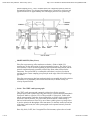
CAFE Description
The CAFE is an instrument to replace the old coude mirror train
with a fiber optic. The project consists of 3 pieces:
1. An optical bench mounted to a port on the Cassegrain
Bonnette which contains a holder for the fiber, feed optics
for the fiber, flat field and spectral (ThAr) calibration lamps,
feed optics for the calibration lamps, and a mechanism to
select between telescope feed and calibration feed. The light
from the telescope will be fed into this optical bench using
the Cassegrain Bonnette central mirror. The electronics for
the optical bench will be controlled from a crate mounted on
the Cassegrain environment.
2. Two fiber optic cables (one for spare) with microlenses on
either end to shape the beam. The fibers will be ~28 m long.
3. Optics for injecting the beam into the Gecko Spectrograph.
This will be a Bowen-Wallraven slicer to which the fiber
cable will be attached. The beam will be injected into the
spectrograph at f/20 as is currently the case with the coude
train.
The CAFE was built for CFHT by Jacques Baudrand, Rene Vitry, and
Michel Lesserter at the Observatoire de Paris-Meudon.
CAFE was first delivered to CFHT at the end of September 1999 and a
preliminary acceptance test was held at CFHT with Jacques Baudrand
and Rene Vitry of OPM during the last two weeks of October. The tests
went well with much progress being made on the controller software in
the two weeks Jacques and Rene were here. Optically and mechanically,
CAFE was shown to be very stable and reliable.
CAFE returned to CFHT in mid-2000 and was used for the first time for
science in July 2000. CAFE is now a commissioned instrument at CFHT
and is the primary feed for Gecko.
F/8 Cassegrain Focus
General Characteristics
This is a classical Cassegrain configuration using a hyperboloidal
secondary mirror. The f/ratio is f/8.00 giving a platescale of 139.4 m
per arcsecond. Field size is limited by the central aperture of the
Cassegrain Bonnette to an unvignetted diameter of 32.2 arcminutes (270
mm). The focal plane is nominally located 400 mm behind the
Cassegrain Bonnette mounting surface. It can be focussed over a range
from approximately 120 mm to 480 mm behind the Bonnette in which
11 of 17
08/07/04 11:26 PM
CFHT Observatory Manual - Observatory (Sec.4)
http://www.cfht.hawaii.edu/Instruments/ObservatoryManual/CFH...
Bonnette field acquisition and guiding are available. For a focus at
distance p (mm) from the nominal focus, the resulting third order
longitudinal spherical aberration is : 7xp microns (p > o if focus down).
Note that since the secondary mirror does not have the correct shape
required, it is permanently distorted in its cell through air bag pressure to
get the stigmatic focus at the nominal position.
Since it is a classical Cassegrain, the on axis image is stigmatic.
However, coma length grows at the rate of 1 arcsecond per 5.7
arcminutes (48 mm) off axis. On-axis optical image quality is currently
limited to about 0.3 arcseconds
FWHM by residual alignment and mirror support errors.
The large secondary mirror produces a 1.58 meter diameter central
obstruction with the upper Cassegrain baffle in place (or a 19% area loss)
TV Guiding
The TV guiding field is roughly 90x70 arc sec. Note that the x’ and y’ axis of the guiding
field can be independently reversed
if needed, using toggles on the monitor. It is direct, i.e. north up and east left, for the
standard Cassegrain environment
position angle ( =0). In this standard position, =0) the X axis is at west, the Y axis at south.
For a positive =0 degto +95 deg
they turn clockwise for a negative ( =0 to -95) they turn counterclockwise. If the TV
monitor is put in the direct mode, the
axes on its display will be oriented in the same way.
Limiting magnitude for autoguiding (in dark period) is V=18 near the center of the guiding
field, but much worse at its edges,
because of a significant amount of coma (coma length is 6 arc sec at the extreme edge of the
guiding field).
The available acquisition field for the x-y stage travel, without vignetting, is limited by an
offset rectangle on its outside,
and a more complicated figure in inside. The latter includes an approximate half circle
centered on the field (at X=O, Y=O,
in coordinates of the bonnette mirror). Its radius, R=77.8 mm (or 9.32 arc min.) at the F/8
focal plane, as drawn on figure,
corresponds to the standard F/8 focus, (400 mm below the Cass. bonnette mounting flange),
and to a vanishing working field.
When using a different focus at a distance L (mm) from the same mounting flange, and a
sizable field of diameter D (mm)
in the F/8 plane, the radius R of the limiting circle given by:
R(mm in the F/8 plane) = 52.8 + (6.25x10⁻³) Lmm + 5x10⁻¹) Dmm or R(arcmin on the sky) = 6.32 + (7.5x10⁻³)
Lmm + (6x10⁻²) Dmm
At high galactic latitude fields, the search for a guiding star can be quite time consuming.
The Observing Assistants
typically use the RASTER bonnette command to speed up the process. The 20 million stars
of the Hubble Guide Star
catalogue are now on-line, with computer-aided selection of the guiding star by the
Observing Assistant.
12 of 17
08/07/04 11:26 PM
CFHT Observatory Manual - Observatory (Sec.4)
http://www.cfht.hawaii.edu/Instruments/ObservatoryManual/CFH...
Focussing
Focussing is done with a special cassegrain focus control box at the observer’s station. Both
coarse and fine encoder
Z values of the longitudinal position of the secondary mirror are displayed on the TCS
monitor. One coarse encoder step
corresponds to a longitudinal displacement of the F/8 focus of ??? microns. Increasing
values correspond to a focus closer
to the bonnette. When inserting a filter of thickness e(mm) and refractive index n, focus on
the detector can be kept by
increasing the coarse focus value by 8(n-1)/n x e(mm) steps.
Cassegrain Environment
Overview
All structures below the primary mirror cell, including the Cassegrain
bonnette, mounted instruments and electronic racks as well as
instrumentation panels, are rotated as a single unit and constitute the
Cassegrain environment. There is a liberal amount of general purpose
standard 19 inch rack space available for instrumentation electronics.
Access to Cassegrain Focus
13 of 17
08/07/04 11:26 PM
CFHT Observatory Manual - Observatory (Sec.4)
http://www.cfht.hawaii.edu/Instruments/ObservatoryManual/CFH...
The Cassegrain focus has no observers cage. A large manlift is available
which permits access except when pointing near the horizon. For such
extreme telescope positions smaller, but higher, manlifts, (Wild Cat), are
available.
Mounting of Equipment
Please advise daycrew of any equipment being mounted in an
out-of-balance position so that a suitable counter balance can be prepared
should Cassegrain environment rotation be desired.
Rotation
Rotation control of the Cassegrain environment is normally done via a
standard handpaddle attached to the main console in the
control/observing room. It could also be similarly controlled from the
unit. Instructions for same are found adjacent to the handpaddles. An
encoder position readout of the Cassegrain environment can be taken
either from the TV monitor at Cassegrain environment or from the fourth
floor monitor. The rotation encoder resolution is approximately 0.1
degrees.
The normal parking position for the Cassegrain environment is zero° (the
long end of the Cassegrain bonnette which contains the acquisition TV
pointing due West). Total rotation available is +/- 95 degrees.
Electric Power
Electrical power for the Cassegrain environment is controlled with the
Cassegrain Focus Panel 2C (CFP2C).
The following D.C. power is available at Cass.
+
5V
12V
15V
24V
48V
at
at
at
at
at
7.2A
2.3A each
2.6A each
2.4A each
5A
The commons for each of these supplies are isolated. They can be tied together if the user
desires.
The 5,12, 15 and 24 volt supplies are controlled by front panel switches on the CFP2C. It is
important that only those
power supplies which are necessary be turned on. The 48 volts supply should be available at
all times. Please turn off all
controllable supplies when not in use.
Distribution of these supplies is at the front panel of the CFP2C. The connectors are
arranged in groups according to the
type of power available e.g. GROUP 5/12 has + 5 volts and ± 12 volts. Detailed information
regarding connector types
and pinouts can be found in the Cassegrain Focus User’s Manual.
The switch labeled "LEDs" on the CFP2C front panel is provided to give a visual indication
of the status of the controllable
14 of 17
08/07/04 11:26 PM
CFHT Observatory Manual - Observatory (Sec.4)
http://www.cfht.hawaii.edu/Instruments/ObservatoryManual/CFH...
D.C. supplies.
The following A.C. power is available at Cass.
220 V.A.C.
50 HZ power is available in standard French sockets
800 watts maximum.
208 V.A.C.
60 HZ 3 phase power is available in standard French sockets
2000 watts maximum.
208 V.A.C.
60 HZ 3 phase power is available in standard American sockets
3000 watts maximum.
110 V.A.C.
60 HZ power is available in several places at Cass.
Instrumentation Cabling
The general purpose instrumentation cabling available at the Cassegrain
focus consists of various sizes of overall shielded twisted pair,
individually shielded twisted pair and coax cables. These connectors run
between the CFP2A (Cassegrain Focus Panel 2A) at the Cassegrain
environment and the CPP2 in the observers room on the fourth floor.
Cryogen Pumping System
A vacuum system is available for pumping on cryogens, as is required with some IR
detectors. There are two separate
lines each connected to a Sargeant-Welch Model 1397 mechanical pump (500 liters/minute)
located on the second floor.
The lines terminate at a manifold which is permanently installed on the Cassegrain
environment. The manifold has valves
which permit the two systems to be used independently or in parallel and vacuum gauges to
monitor the pressure. The
connection between the manifold and the cryostat is made with flexible plastic tubing and
Klamp Flange or Alcatel KF
10 or 16 fittings.
Observers needing this facility must so specify on the Visitor Instrument Questionnaire and
on the Guest Observer
Information Sheet. Note that use of the system severely restricts the range of rotation of the
Cassegrain environment.
If this is a potential problem, it should be discussed with CFHT staff well in advance of the
run.
Cassegrain Bonnette
Overview
15 of 17
08/07/04 11:26 PM
CFHT Observatory Manual - Observatory (Sec.4)
http://www.cfht.hawaii.edu/Instruments/ObservatoryManual/CFH...
Instruments at the F/8 and F/36 Cassegrain focii are mounted on the
Cassegrain Bonnette, which provides a TV camera to monitor the field, a
retractable field finder and a guiding probe. Maximum capacity and
maximum moment with respect to the mounting plate are respectively.
Mounting face C1:
Mounting face C2:
Mounting face C3:
Mounting face C4:
100 kg and 600 NM.
300 kg and 1800 NM.
450 kg and 2700 NM.
750 kg and 4500 NM.
Clearances from the back surface of the Cassegrain guiding head are as
follows:
o
o
(1) to observing floor (declination limits about -30 to +72 )
- 3.00 m.
(2) to north pier (for declinations less than -30 o) - 1.48 m.
(3) to south pier (for declinations greater than +72 o ) - 1.61
m.
It is also possible to use a flat mirror to send the beam to the side of the guiding head. Four
positions are available at
o
90 intervals.
The useful field is 4 arc minute. Maximum capacity on a side port is 50 kg and maximum
moment with respect to the
mounting plate 150 NM.
Mounting of Equipment
The pitch circle and threaded hole sizes for the base of the Cassegrain bonnette are given in
an instrument mounting
diagram. Several spacers are available to bring the instrument focus close to the nominal
telescope focus, 400 mm below
the cass bonnette instrument mounting surface. Suitable centering rings are also available,
should the instrument register
requires changing from the normal male register to a female one.
For special applications a side port is also available for mounting small instruments. Contact
the Director prior to proposing
use of this side port.
TV Guiding System
The Cassegrain Bonnette contains a low light level TV for field acquisition and guiding. A
remote controlled mirror is used to
center the TV field at various x,y (orthogonal coordinates in the bonnette plane) locations.
The center of the field is close to
x=0 mm, y=0 mm. The area for the F/8 is roughly 60 arcsec x 70 arcsec. TV guiding fields
orientations, as a function of the
Cass. environment position angle.
Computer Control
16 of 17
08/07/04 11:26 PM
CFHT Observatory Manual - Observatory (Sec.4)
http://www.cfht.hawaii.edu/Instruments/ObservatoryManual/CFH...
The xy stage and central mirror as well as the focus motions of both the TV
acquisition/guide system and the knife edge
assembly are controlled by the TCS computer. In addition to the commands involving
motion to a given x,y position and
focus (Z’), the xy stage can be commanded to move with a given velocity for cometary or
planetary observations. The
velocity mode control program now provides improved velocity resolution and minimum
velocity rates. Other facilities such
as spiral searches, rastering and position recording are available. The status of the bonnette
is displayed continuously on
one of the console monitors.
Observational TV Systems
Low light level television (LLLTV) cameras are used at telescope focal positions to acquire object
fields and to provide offset
guide information. These cameras are ISIT type cameras. These cameras can also be mounted to
visitor instruments.
Mechanical information is readily available to make this adaptation, but advance planning is
required. Video from the offset
guide field is sent to a digitizer and integrator to provide automatic guide data.
Autoguider
When a guide star is chosen and the tracking rate of the telescope has been controlled
by the Observing Assistant, the astronomer can operate in the autoguider mode. It is
put in operation by the O.A. and generally performs well. In actual operation 16x16
pixels, each 0.46 x 0.38 arc sec wide, centered on the star are digitized, the centroid is
calculated by real time software and the resulting corrections sent to the telescope
control system. Careful flexure measurements on the telescope have shown that an
accuracy of at least 0.1 arc second per hour is attained at F/8.
Version 1.0 January, 2003
Copyright (c) CFHT. All rights reserved.
This page was last modified on: Fri, 07 Nov 2003 08:48:10 GMT
Comments to: "website at cfht.hawaii.edu"
17 of 17
Home, News, Observing, Science,
Images, Outreach, OurUsers
08/07/04 11:26 PM
CFHT Observatory Manual - Observatory (Sec.5)
http://www.cfht.hawaii.edu/Instruments/ObservatoryManual/CFH...
CFHT Observatory Manual
Section 5 - INSTRUMENTS
TABLE OF CONTENTS
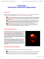
Overview
Currently available instruments are listed and are briefly described in this manual.
More complete operational manuals are available in Instrument Manuals.
Present CFHT instruments cover the following uses:
0.3 to 1 micron wide field imagery, at prime focus (MegaCam/MegaPrime);
(replacing the CFH12K mosaic)
1.2 to 2.5 micron imaging at f/8 using the AOB/PUEO with KIR, or the CFHT
IR camera; (and soon WIRCam)
0.36 to 1 micron low-to-medium resolution and multi-slit spectroscopy at f/8
Cass. focus (MOS/OSIS);
0.4 to 0.7 micron Fabry-Pérot spectroscopy at f/8 Cass focus MOS-FP or
OSIS-FP;
0.3 to 1 micron high resolution stellar spectroscopy at coudé focus (CFHT
coudé spectrograph Gecko and Gecko with fiber feed CAFE);
Visible instruments are CCD-based. The coudé spectrograph can use the
MIT2, or EEV1, detectors.
Also, CFHT astronomers are involved in future Instrumentation Projects:
ESPaDOnS, an Echelle SpectroPolarimetric Device for the Observation of
Stars at CFHT is under construction
WIRCam, the CFHT wide-field infrared camera (20’x20’, 0.3" pixels) is at the
final design review stage.
‘OHANA, the optical Hawaiian Array for Nanoradian Astronomy) project.
Data Acquisition and Instrument Control
The summit data acquisition and instrument control system, the Hale Pohaku data
reduction system, and the Waimea observing, permanent record/software
development/data reduction facilities function in a fully integrated way via:
1 of 10
08/07/04 11:26 PM
CFHT Observatory Manual - Observatory (Sec.5)
2 of 10
http://www.cfht.hawaii.edu/Instruments/ObservatoryManual/CFH...
08/07/04 11:26 PM
CFHT Observatory Manual - Observatory (Sec.5)
http://www.cfht.hawaii.edu/Instruments/ObservatoryManual/CFH...
At the summit there are several HP workstations, LINUX workstations, and
Xterminals. Another set of terminals are at Hale Pohaku, and several terminals are at
the Waimea Headquarters. There are also Sun Sparcstations at the summit, another at
Hale Pohaku, and several in Waimea. A fiber link exists between the summit and
Hale Pohaku.
The arrangement of having the display in a different machine of the one actually
taking the data or controlling the instrument, permits us to run the observing
environment from any machine with a suitable display in the network. However, only
one login session for a particular instrument is permitted to avoid any interference
with the present observer’s run. Other logins for different instruments are available to
permit development, debugging and preparations prior to the scheduled observing
run.
Instrument Control
Currently, all our controllers are purchased from Bob Leach at San
Diego State University. These consist of a set of boards providing the
analog and the digital functions, and are based around the Motorola
56000 Digital Signal Processor (DSP).
MegaCam uses a controller designed at the C.E.A. in France by Jean de
Kat, which is based on Analog Devices’ "sharc’’ DSP. This new
controller handles the higher readout speeds of MegaCam. The guide
CCDs for MegaCam use the San Diego State controller.
A controller for WIRCAM (under development) has not yet been
determined.
All controllers currently use fiber optic links to send pixel data down to
the 4th floor computer room.
Pegasus User’s Interface
The HP machines, and PC Linux workstations, are used for data
acquisition and instrument control running under the Unix operating
system. The vast majority of the programs are written in the C
programming language and use the X-window standard. Details of the
Pegasus system can be found in the Pegasus User’s Manual.
The user interface environment is built on top of the X-window system
and consist of a "Session Manager" and "Feed Back" windows. The main
interactions mode is "point and click". When the user sees a desired
command, mode, action, etc. the mouse is moved over the appropriately
labeled gadget and the left mouse button is pressed. Windows come and
go automatically, as do status icons. No window knowledge is required
of the user.
3 of 10
08/07/04 11:26 PM
CFHT Observatory Manual - Observatory (Sec.5)
http://www.cfht.hawaii.edu/Instruments/ObservatoryManual/CFH...
At login the Session Manager and the Feed Back windows appear
automatically. The Session Manager window contains a set of buttons
which has been tuned to the particular instrument configuration. When
an item has been selected (click) a "forms" window will appear.
Forms are the main way to communicate with a program. They, for
instance, allow writing parameters in text input fields (such as the
integration time for a CCD exposure) and deciding actions through
checked boxes (e.g., click the ACCEPT push button will to begin a CCD
exposure). For actions that take a long time (CCD integration, filter
wheel movement, etc.) a visual icon will appear on the screen to identify
the state of that resource or program. These icons go away when the
action is completed.
The "feedback" window contains a stream of output messages from the
action taking place, each action being a separate program which starts
up, does its work, and then dies. This allows writing UNIX or IRAF
scripts to manage sophisticated observing situations. It is also possible to
use normal UNIX command interpreters to run any of our programs
providing terminal access as well as our normal windowed environment.
Instruments
Prime Focus Environment with the WFC and MegaCam - MegaPrime
The new prime focus upper end (PFUE) has been designed at CFHT with the help of
INSU-Division Technique: a new base ring, a new set of spiders, and a prime focus
base which will receive all the other components of MegaPrime. The PFUE has been
built on the West Coast of the USA by L&F Ind.
In addition to its basic structure, the PFUE provides a temperature controlled
environment for MegaCam and its readout electronics. A temperature controlled
enclosure for the electronics of MegaPrime is installed on the telescope "caisson
central" .
The Wide Field Corrector (WFC)
The parabolic main mirror of the telescope alone does not produce a
good image of the whole field of view, and so a WideField Corrector
(WFC) is installed in front of the camera.
The WFC has been designed at HIA (Victoria, Canada). The lenses have
been fabricated by SAGEM/REOSC, which also built the mechanical
structure of the WFC and coated the lenses.
A succession of lenses and baffling rings ultimately extends to the
mosaic of MegaCam.
The Focus Stage Assembly
4 of 10
08/07/04 11:26 PM
CFHT Observatory Manual - Observatory (Sec.5)
http://www.cfht.hawaii.edu/Instruments/ObservatoryManual/CFH...
To accommodate the changes in focal length of the telescope with
temperature, and the focus position changes induced by the various
filters, the camera must be able to move along the optical axis of the
telescope. The focus stage assembly (FSA) accommodates this motion,
supporting the camera and its shutter on a motorized stage bolted on top
of the upper end platform. In order to follow the apparent motion of the
sky due to the Earth’s rotation, two small cameras fix on stars outside of
the field of view, providing automatic guidance of the telescope and
measurements of the focal changes.
MegaCam
At the heart of MegaPrime is MegaCam, a unique camera built by the
"Département d’Astrophysique, de Physique des Particules, de Physique
Nucléaire et de l’Instrumentation Associée" at the French
"Commissariat à l’Energie Atomique" (CEA). In addition to a cryostat
housing the mosaic, and its cryogenics system to maintain it cold, CEA
built the camera shutter, the filter jukebox and the electronics to acquire
the image and send it to a computer through fiber optics cables.
AOB/PUEO with KIR
The Adaptive Optics Bonnette (AOB), also called PUEO after the sharp vision
Hawaiian owl, was developed for the Canada-France-Hawaii Telescope, based on
F.Roddier’s curvature concept. The ‘‘bonnette’’ (adaptor) is a facility instrument
mounted at the f/8 Cassegrain focus of the CFH 3.6 m telescope on top of Mauna Kea
(Hawaii). The instrument is the result of a collaborative effort between several
institutes : The CFHT (managing the project and designing the general user
interface); The Dominion Astrophysical Observatory (Canada) who designed and
fabricated the opto-mechanical bench, the curvature wavefront sensor and its
electronics; the company Cilas (France) who provided the deformable curvature
mirror and the Real Time Computer and software, including a high level maintenance
interface; the Observatoire de Paris-Meudon (France) who manufactured the separate
tip-tilt mirror and was in charge with the final integration, testing and calibration of
the instrument. The UH adaptive optics team provided guidance throughout the
project. The system was commissioned at CFHT during three runs in the first
semester 1996.
KIR is a high resolution 1024 x 1024 near-infrared camera based on the Rockwell
Science Center HAWAII (HgCdTe Astronomical Wide Area Infrared Imaging) focal
plane array. This array is sensitive to radiation from 0.7 to 2.5 microns. KIR has been
designed to be used at the F/20 output focus of PUEO, the CFHT Adaptive Optics
Bonnette (AOB). It consists in an LN2 cryostat which harbors the detector, the fixed
0.67:1.0 transfer optics, an F/20 cold stop and a filter wheel. The standard I, J, H, K
and K’ broad-band filters are available, as well as several narrow-band filters. A
preamplifier and a shutter are mounted externally to the dewar. The system is driven
by an SDSU/Leach CCD controller which is the controller commonly used at CFHT
for all visible and infrared detectors. The system provides the observers with a user
interface , called DetI, incorporated into the CFHT/Pegasus observing environment,
through which they will configure the camera, control the data acquisition, monitor
the data storage and do some pre-processing.
The Dewar has been constructed by the Universite de Montreal, part of the array DSP
code by the Observatoire Midi-Pyrenees. The acquisition system and software were
under the responsability of CFHT. The final integration of the science grade detector
has been carried out at CFHT. The first light has been obtained during the first
5 of 10
08/07/04 11:26 PM
CFHT Observatory Manual - Observatory (Sec.5)
http://www.cfht.hawaii.edu/Instruments/ObservatoryManual/CFH...
technical run in September 1997 and the final acceptance as well as the first
astronomical observations were carried out in December 1997 and January 1998.
GriF
GriF is an upgrade to KIR that allows integral field spectroscopy in the K band, with
a spatial resolution at the diffraction limit of the telescope (~0.12") using PUEO, the
CFHT adaptive optics bonnette . It consists of a (warm) Fabry Perot interferometer,
coupled with a grism in the KIR filter wheel, that disperses the Fabry Perot orders. A
rectangular field selector in the focal plane (~6" x 36" on the sky) prevents the orders
from overlapping spatially on the detector.
The Fabry Perot Perot mode will be available for 2004A, although narrow band filters
will need to be used for order sorting . The focal plane wheel, which normally allows
for coronography, long slit spectroscopy and the cross dispersed mode is undergoing
major redesign and will not be available for 2004A.
CFHTIR
CFHT-IR is a general purpose 1024 x 1024 near-infrared camera for direct imaging at
the F/8 Cassegrain focus (0.2" pixels, 3.5’ FOV). It has also been in the past the
infrared detector for multi-object spectroscopy with OSIS. CFHT-IR has been
developed as a collaborative effort between Université de Montréal and CFHT.
Commissioning took place in November 2000 and CFHT-IR has been regularly used
for science since then.
MOS/OSIS
At a meeting in 1986, the CFHT users’ community identified a low spectral
resolution multi-object spectrograph as one of the highest priorities for new
instrumentation at CFHT. Although the original intermediate dispersion
spectrographs constructed for the CFHT had high throughput and were of excellent
optical and mechanical quality, they were designed for single slit observations with
image intensifiers or electronographic cameras as detectors. The desire to observe
many faint objects simultaneously and also the realization that the image quality at
CFHT is routinely better than one arcsecond led to the design of the MOS/SIS
spectrograph, a dual Multi-Object and Subarcsecond Imaging Spectrograph. It is
composed, in fact, of two distinct spectrographs sharing a common interface with the
telescope after the Cassegrain bonnette: one is optimized for multi-object
observations over a large field (MOS), the other (SIS) for high spatial resolution
observations incorporating rapid tip/tilt image stabilization similar to that very
successfully used in the CFHT/DAO high resolution camera HRCam (McClure et al.
1989). Two movable 45 degree mirrors permit a feed to either MOS or SIS. The
MOS/SIS spectrograph was jointly designed and built by teams from the Dominion
Astrophysical Observatory (DAO) in Victoria, theObservatoire de Paris-Meudon
(OPM), the Observatoire de Marseille andCFHT. Work began on the designs in May
1988 and resulted in an instrument which saw its first light in July 1992. For several
years from that time, MOS/SIS was the most popular instrument at CFHT. With the
advent of wide-field imaging and regular AOB observations, it has taken a smaller,
but still quite significant role in the observering schedule. MOS/OSIS have accounted
for 25 - 30 night per semester over the past few semesters (Sept 2001).
MOS is primarily designed for multi-aperture spectroscopy over a 10´ x 10´ field,
just covered with a 2048 x 2048 15 µm pixel CCD. This gives images with a correct
6 of 10
08/07/04 11:26 PM
CFHT Observatory Manual - Observatory (Sec.5)
http://www.cfht.hawaii.edu/Instruments/ObservatoryManual/CFH...
spatial sampling of 0.8". This is considered the best compromise between field size
and spatial resolution. The designed wavelength range is from 365 to 1000 nm, and
typical efficiencies are approximately 80% for imagery and 60% for spectroscopy.
MOSFP/OSISFP (Fabry-Perot)
Fabry-Perot spectroscopy offers moderate resolution (~5000 to 10000) 2-D
spectroscopy for the observation of various astronomical sources. The field of view
varies between 1 and 10 arcmin depending on the intrumental configuration, and the
spectral resolution depends essentially on the Fabry-Perot etalon inserted in the
instrument. The spectral PSF is oversampled so that there is no lost of resolution
resulting from a coarser sampling (except maybe at the edge of the field with a large
gap etalon).
Fabry-Perot spectroscopy has been used particularly on extended objects like galaxies
and nebulae. It is particularly efficient for emission lines, to obtain velocity or
velocity dispersion fields.
Gecko - The CFHT coudé spectrograph
The CFHT coudé spectrograph, commonly referred to as Gecko, provides
spectroscopists with a spectral resolving power R up to 120,000 from the atmospheric
cutoff near 3000Å to 1µm for CCD’s with up to 4400 13.5µm pixels. Unlike most
echelle spectrographs, Gecko has been optimized for use with a single spectral order
(between 5 and 18) from the 316 groove/mm echellette mosaic. Order sorting is
achieved with interference filters or by one of three variable grisms. An image slicer
is used to optimize the throughput of the instrument. To minimize traffic into and out
of the inner coudé room, the entire spectrograph can be operated remotely from the
control room.
Since July 2000, CAFE, the CAssegrain Fiber Environment, replaces the red coudé
7 of 10
08/07/04 11:26 PM
CFHT Observatory Manual - Observatory (Sec.5)
http://www.cfht.hawaii.edu/Instruments/ObservatoryManual/CFH...
mirror train with optical fibers. CAFE consists of an optical bench mounted to a port
on the Cassegrain Bonnette, two fiber optic cables and a Bowen-Wallraven slicer for
injecting the beam into the Gecko Spectrograph.
A "fiber agitator" (which agitates the optical fiber with an amplitude of 1 mm and a
frequency of 30 Hz) has been installed to prevent modal noise and the S/N
degradation associated with it. Flat field correction seems to be better than with the
coudé mirror train.
CAFE - (A Fiber Feed to Gecko)
The CAFE is an instrument that replaces the old coude mirror train with a fiber optic.
The project consists of 3 pieces:
1) An optical bench mounted to a port on the Cassegrain Bonnette which contains a
holder for the fiber, feed optics for the fiber, flat field and spectral (ThAr) calibration
lamps, feed optics for the calibration lamps, and a mechanism to select between
telescope feed and calibration feed. The light from the telescope is fed into this
optical bench using the Cassegrain Bonnette central mirror. The electronics for the
optical bench is controlled from a crate mounted on the Cassegrain environment.
2) Two fiber optic cables (one for spare) with microlenses on either end to shape the
beam. The fibers are ~28 m long.
3) Optics for injecting the beam into the Gecko Spectrograph. This is a
Bowen-Wallraven slicer to which the fiber cable is attached. The beam is injected
into the spectrograph at f/20 as is was the case with the coude train.
The CAFE was built for CFHT by Jacques Baudrand, Rene Vitry, and Michel
Lesserter at the Observatoire de Paris-Meudon.
CAFE was first delivered to CFHT at the end of September 1999 and a preliminary
acceptance test was held at CFHT with Jacques Baudrand and Rene Vitry of OPM
during the last two weeks of October. The tests went well with much progress being
made on the controller software in the two weeks Jacques and Rene were here.
Optically and mechanically, CAFE was shown to be very stable and reliable.
CAFE returned to CFHT in mid-2000 and was used for the first time for science in
July 2000. CAFE is now a commissioned instrument at CFHT and is the primary feed
for Gecko.
Filters
The CFHT filter list is available in a companion document (CFHT Filters).
Grisms
The MOS/OSIS grism information is provided in two tables, one for MOS/OSIS
visible, the other one for OSIS-IR.
Gumball
8 of 10
08/07/04 11:26 PM
CFHT Observatory Manual - Observatory (Sec.5)
http://www.cfht.hawaii.edu/Instruments/ObservatoryManual/CFH...
At the beginning of 1998, an upgraded version of the Gumball calibration unit was
commissioned at CFHT. Not only optomechanics and electronics components were
modified or changed but a new Pegasus interface was also implemented. For an
observer, the major changes include the possibility to define different exposure times
for each lamp for the same calibration frame, pre-defined setups for diverse
intrumental configurations to optimize the utilisation of the Gumball, and the
availability of two Fabry-Perot interferometers providing regularly spaced calibration
lines over large spectral ranges. See the Gumball Web Page for more information.
LAMA
LAMA (LAzer MAchine) - This is a Micro-Control YAG laser driller, which has
been installed by CFHT in 1990, with the help of the Observatoire de Marseille.
Maximum size of the drilling section is 150x150mm.
Currently for the MOS/SIS, we are using 75 microns thick, black anodized,
commercial aluminum wafers. The practical limit for the minimum width of the slits
is 0.25 arc sec. at f/8. Residual r.m.s. drilling errors on the slit edges are about 2
microns.
With recent refinements of the system, especially the adoption of a travelling
salesman algorithm to speed up transfer time of the x-y stage from one slit position to
another, drilling time, including data transfer to the LAMA controller, is typically 20
minutes for 150 slitlets (say 1.5 arc sec. x 12 arc sec. each). To this value, one must
add ~10-15 minutes for various overheads, quite independent of the number of slits.
Note that these values are quite comparable to typical integration time (except for
very faint objects), and the observers are strongly encouraged to plan their observing
sequences as well as possible. In particular, during long MOS/SIS multi- slit runs, it
makes sense that each observer makes a couple of images for his/her successor, so
that a run can start with a few masks already quietly made during the day.
9 of 10
08/07/04 11:26 PM
CFHT Observatory Manual - Observatory (Sec.5)
http://www.cfht.hawaii.edu/Instruments/ObservatoryManual/CFH...
Detectors
CCD Cameras
Optical: CCD Mosaic
MegaPrime/MegaCam
Optical: single CCD [ Table of CCDs ]
EEV1 - 2048 × 4500 - backside illuminated
MIT2 (for use with Gecko only) - 2048 x 4096 - Thinned backside illuminated
Infrared: single IRFPA
CFHT-IR - 1024 2 HgCdTe
KIR - 10242 HgCdTe
Version 1.0 January, 2003
Copyright (c) CFHT. All rights reserved.
This page was last modified on: Fri, 07 Nov 2003 12:14:55 GMT
Comments to: "website at cfht.hawaii.edu"
10 of 10
Home, News, Observing, Science,
Images, Outreach, OurUsers
08/07/04 11:26 PM
CFHT’s Web page for ESPaDOnS
http://www.cfht.hawaii.edu/Instruments/Spectroscopy/Espadons/
CFHT, Instruments, Spectroscopy, ESPaDOnS
ESPaDOnS: an Echelle SpectroPolarimetric
Device
for the Observation of Stars at CFHT
A Franco-Canadian project
managed by
Jean-François Donati , Claude Catala and John Landstreet
Tentative schedule and latest news from CFHT (Updated July 02)
CFHT is glad to announce that ESPaDOnS has received the final approval for acceptance and
shipping to Hawaii. ESPaDOnS in now en route to Hawaii.
After re-assembly, alignment, and daytime tests, ESPaDOnS will go on the sky for engineering (see
the Observing Schedule for 2004B for the detailed schedule). CFHT will provide the Graphical User
Interface. Most of the work at the telescope will probably involve integration with the Telescope
Control System and using the Guider with real stars.
Characteristics and Performances
For official information and numbers, please see the official ESPaDOnS webpage.
Other relevant documents
1.
2.
3.
4.
5.
6.
Development Responsibilities List
Presentation made to the CFHT Board of Directors, December 2000
Presentation made to the CFHT Science Advisory Committee, November 2001
Presentation made to the CFHT Science Advisory Committee, November 2002
Presentation made to the CFHT Science Advisory Committee, November 2003
Presentation made to the Board of Directors, December 2003
http://www.cfht.hawaii.edu/Instruments/Spectroscopy/Espadons/
This CFHT Web page is maintained by Nadine Manset (manset -=AT=- cfht.hawaii.edu)
Copyright (c) CFHT. All rights reserved.
This page was last modified on: Fri, 02 Jul 2004 23:21:28 GMT
Comments to: "website at cfht.hawaii.edu"
1 of 2
Home, News, Observing, Science,
Images, Outreach, OurUsers
08/07/04 11:27 PM
CFHT’s Web page for ESPaDOnS
2 of 2
http://www.cfht.hawaii.edu/Instruments/Spectroscopy/Espadons/
08/07/04 11:27 PM
Home Page of ESPaDOnS project
http://webast.ast.obs-mip.fr/magnetisme/espadons.html
ESPaDOnS
the new generation stellar spectropolarimeter
Latest information and results:
Designed and constructed at Observatoire Midi-Pyrénées (OMP) in France, ESPaDOnS, the new generation stellar
spectropolarimeter, is now fully operational at OMP, accepted by the CFHT technical staff and is about to be shipped and
installed at CFHT. The results of all tests that were carried out are progressively posted on this page. In particular, you can (or
will soon) find here the following information:
design and performances of ESPaDOnS:
instrument details and configurations
spectral domain and resolution
spectral response and global efficiency
thermal response and spectral stability
performances of Fresnel rhomb retarders
ccd readout modes and characteristics
control and data reduction software tools of ESPaDOnS:
control software and user interface
viewing, guiding and exposure meter facilities
temperature and pressure monitoring
observing procedures
data reduction routines
observing with ESPaDOnS:
instrument status
observers’ guide
exposure time calculator
documentation, picture gallery and credits:
© Ken Done
related documentation (restricted access)
description of critical items
examples of frames
examples of spectra
picture gallery
project team and budget
This web page is the only official ESPaDOnS site and information source. Whatever information you find or hear on
ESPaDOnS either reflects what is described on this site (and is probably carbon copied from it) or should be regarded as highly
uncertain and most likely erroneous. The old (and mostly out of date) ESPaDOnS web site can still be accessed at this address.
ESPaDOnS is a collaborative project funded by France (CNRS, MENESR, OMP, LATT), Canada (NSERC), CFHT and ESA.
1 of 2
08/07/04 11:28 PM
Home Page of ESPaDOnS project
http://webast.ast.obs-mip.fr/magnetisme/espadons.html
© Jean-François Donati, last update June 15 2004; statistics:
2 of 2
08/07/04 11:28 PM
ESPaDOnS: instrument details and configurations
http://webast.ast.obs-mip.fr/magnetisme/espadons_new/configs.html
ESPaDOnS
Instrument details and configurations
Overview
ESPaDOnS is a bench-mounted high-resolution echelle spectrograph/spectropolarimeter fibre-fed from a Cassegrain module
including calibration and guiding facilities, as well as an optional polarisation analyser. It can deliver:
a complete optical spectrum (from 370 to 1,050 nm) in a single exposure with a resolving power of about 68,000 (in
spectropolarimetric and ’object+sky’ spectroscopic mode) and up to 81,000 (in ’object only’ spectroscopic mode); with a
79 gr/mm grating and a 2kx4.5k ccd detector, the full spectrum spans 40 grating orders (from order #61 in the blue to
order #22 in the red);
15% to 20% peak throughput (telescope and detector included); this performance is obtained thanks to the very
efficient dual pupil design of Baranne (along which many modern spectrographs such as uves, feros and harps were
designed) as well as to the most recent advances in glass and coating technologies (allowing to produce large dioptric
optics with low reflectance and absorption as well as high efficiency optical fibres and image slicers);
continuum subtracted linear and circular polarisation spectra of the stellar light (in polarimetric mode); using
Fresnel rhombs instead of standard cristalline plates suppresses the usual problems of interference patterns in the
collected spectra, with the additional advantage of being much more achromatic.
Main scientific drivers
With ESPaDOnS, astronomers can now address with unprecedented detail
a broad range of important issues in stellar physics, from stellar magnetic
fields to extrasolar planets, from stellar surface inhomogeneities and surface
differential rotation to activity cycles and magnetic braking, from
microscopic diffusion to turbulence, convection and circulation in stellar
interiors, from abundances and pulsations in stellar atmospheres to stellar
winds and accretion discs, from the early phases of stellar formation to the
late stages of stellar evolution, from extended circumstellar environments to
distant interstellar medium.
The image on the right (obtained by Moira Jardine and collaborators)
illustrates one of such scientific programs. It shows a 3D magnetospheric
configuration extrapolated from a magnetic surface map of the young
ZAMS star AB Doradus, derived from spectropolarimetric data such as
those ESPaDOnS can secure. The image shows X-ray emission from the
high temperature plasma filling the closed magnetospheric loops (the stellar
surface being depicted here as the central dark sphere in which the loops
are anchored).
Brief instrument description
ESPaDOns consists of two distinct units, each located at a different place with respect to the telescope:
the Cassegrain unit, mounted at Cassegrain focus, includes the calibration/guiding module as well as the polarimeter
module;
the spectroscopic unit, installed in a thermally stable room right at the heart of the telescope building (the Coude
room), includes the spectrograph module (the core item of ESPaDOnS in terms of cost and weight) fed from the
1 of 3
08/07/04 11:28 PM
ESPaDOnS: instrument details and configurations
http://webast.ast.obs-mip.fr/magnetisme/espadons_new/configs.html
Cassegrain unit by the fibre link and image slicer module.
The specific role of these four modules is described below:
the calibration/guiding module includes an atmospheric dispersion corrector (made of 2 separate null-deviation
prisms rotating independantly from each other and cancelling out in
real time the atmospheric refraction), a compact 1kx1k ccd camera
looking at the instrument aperture (that can be used to autoguide on
the star of interest or on any other star present in the 100" camera field
of view), and a calibration wheel that can replace the stellar beam by
various sorts of calibration light (composite featureless spectra from
tungsten lamps for flat fielding purposes, thorium spectra used as a
wavelength reference, fully polarised light with known directions of
vibration);
the polarimeter, including one quarter-wave and two half-wave
Fresnel rhombs coupled to a Wollaston prism, provides a very
achromatic polarisation analysis of the stellar light without producing
the usual spectral interference patterns; two images of the main 1.6"
instrument aperture are produced at polarimeter output, each image
gathering the photons from the incoming beam associated with one of
the two orthogonal vibration states of the selected polarisation); the
optical design on the right shows the beam passing through the
instrument aperture (top right of image), through the three rhombs
and Wollaston prism (performing the polarisation analysis and
duplicating the input beam) and through the two reimaging triplets
(working at infinite conjugate ratio and bracketing the polarisation
optics), before being refocussed on the optical fibres (bottom left of
image, not shown on picture);
in non polarimetric mode, the Wollaston prism is removed and
replaced with a wedge plate producing at polarimeter output a single image gathering all photons from the incoming
beam (a second image is also produced in this mode, gathering photons from a second instrument aperture offset from
the main one by about 8" and with which we estimate the spectral contribution from the sky background, if needed);
the multiple fibre link collects photons at polarimeter output (one fibre per image) and conveys them to a tunable
Bowen-Walraven image slicer device (with attendant optics) at the entrance of the spectrograph; this device slices the
twin circular images of the fiber heads at a rate of 3 or 6 slices per fibre (depending on the selected instrument
configuration) into a pair of narrow images at the spectrograph slit level; a peak fraction of about 40% to 45% of the
stellar photons that reached the telescope made their way through the previous instrument modules and are injected
into the spectrograph;
the spectrograph, set up in dual pupil configuration, features a 190mm pupil, a double set of high-reflectance
collimators (cut from a single 680mm parabolic
parent with 1500mm focal length), a 79 gr/mm
R2 200x400mm monolithic grating, a fully
dioptric f/2 camera with 388mm focal lens and
a 210mm free diameter (7 lenses in 4 blocks,
one of them being a 220mm quadruplet), a high
dispersion prism crossdisperser (made of a
train of 2 identical PBL25Y prisms with 35deg
apex and 220mm cross section) and a ccd
detector with 2kx4.5k 0.0135mm square pixels;
the optical design on the right shows the beam
entering the spectrograph (in dark blue, just
below the grating in the top centre of image),
bouncing successively off the main collimator,
grating, main collimator, flat mirror and
transfer collimator (all shown as light green
surfaces in the image) before passing trough
the double prism cross disperser, the 4-block
fully dipotric camera and the ccd dewar
window (all shown as light blue volumes);
this configuration yields full spectral coverage
of the optical domain (from grating order #61
centred at 372nm to grating order #22 centred
at 1029nm) in a single exposure with a
resolution in excess of 65,000; the peak
throughput of the spectrograph (with ccd
detector) is about 40% to 45%, bringing the total instrument peak efficiency at a level of about 15% to 20%.
2 of 3
08/07/04 11:28 PM
ESPaDOnS: instrument details and configurations
http://webast.ast.obs-mip.fr/magnetisme/espadons_new/configs.html
Instrument configurations
To keep ESPaDOnS as simple as possible, it has been designed as a ’point and shoot’ instrument with very few different
configurations. Only three choices are available:
a spectropolarimetric mode in which the two orthogonal states of a given polarisation - either circular (Stokes V) or
linear (Stokes Q or U) - are recorded throughout the whole spectral range; the two spectra are recorded simultaneously
on the ccd detector with the two sets of orders interleaved; the two fibre images are sliced in 3 at spectrograph entrance,
yielding an average spectral resolution of about 68,000;
a first spectroscopic mode (called ’object+sky’) in which the spectra of the star and of the background sky are
recorded simultaneously on the ccd detector (with orders interleaved); again, the two fibre images are sliced in 3 at
spectrograph entrance, and the average spectral resolution is about 68,000;
a second spectroscopic mode (called ’object only’) in which we only collect the spectrum from the star and neglect
that from the background sky (for objects bright enough to outshine the sky background); in this case, the single fibre
image is sliced in 6 at spectrograph entrance, bringing the average spectral resolution to about 81,000.
© Jean-François Donati, last update May 18 2004
3 of 3
08/07/04 11:28 PM
ESPaDOnS: spectral domain and resolution
http://webast.ast.obs-mip.fr/magnetisme/espadons_new/resol.html
ESPaDOnS
Spectral domain and resolution
Echelle orders
The image on the right represents an example flat field frame
taken with ESPaDOnS in polarimetric mode (using light from
a combination of tungsten lamps and filters so that all orders
get a reasonable illumination level). Orders are clearly visible
on this image, where they show up as bright slightly curved
strips running vertically, successive orders being stacked next
to each other from the left to the right of the ccd. As obvious
from this image, the order separation varies with wavelength,
being largest in the blue (right side of image) and smallest in
the red (left side of image) as expected from a prism
crossdisperser. A close up view of the small scale structure of
the orders is displayed in the insert (bottom right of image),
where the two spectra associated to each order in polarimetric
mode (one spectrum per orthogonal state of the selected
polarisation to be measured) are clearly visible.
Up to 40 orders are visible on the image, the first one being
order #22 (centred at 1029nm) on the left side of the chip and
the last one being order #61 (centred at 372nm) on the right
side of the chip. Apart from very small gaps on the edges of the
3 reddest orders (between 922.4 and 923.4, 960.8 and 963.6nm,
1002.6 and 1007.4nm), the wavelength coverage is complete
from 369 to 1048nm and can be obtained in a single exposure.
When reducing the data, the first operation consists at tracking
the location and shape of all orders across the whole chip to a
rms accuracy of better than 0.1pxl.
Wavelength calibration
The image on the right represents an example calibration
frame taken with ESPaDOnS in polarimetric mode (using light
from a combination of a thorium/argon and a thorium/neon
lamp with filters to minimise the amount of strong red lines
blooming the chip). As obvious from this image, a very large
number of lines are present in each order, from which the
accurate relation between pixel number along and across each
order can be derived. The spectral resolution achieved is
derived from the width of these lines. A close up view of the
individual thorium lines is shown in the insert (bottom right of
image) where one can see again the dual structure of each
order (the gap between the two spectra as well as the
instrumental width of the lines (slightly lower than 2pxl).
1 of 2
08/07/04 11:29 PM
ESPaDOnS: spectral domain and resolution
http://webast.ast.obs-mip.fr/magnetisme/espadons_new/resol.html
An average number of about 50 lines per order (about 2,000
lines in total) are automatically searched for by the reduction
routine and identified using reference lists of thorium line
wavelengths; from these, wavelength calibration polynomials
are produced over the full spectral range. The typical accuracy
of this calibration is found to be of order of 0.06pxl or 150m/s at
each given wavelength.
The few remaining neon lines blooming the ccd in the red part
of the domain do not really affect the precision of the
calibration procedure.
Spectral resolution
By measuring the full width at half maximum of the individual
thorium lines (reflecting mostly the instrumental broadening),
one can determine the spectral resolution of ESPaDOnS in the
selected instrument configuration (the reduction code does it
automatically).
The graph on the right shows an example of such thorium lines
(the strongest of the 3 being the ThI line at 550.75385nm). The
full line indicates the wavelength calibrated spectrum around
this line derived with ESPaDOnS being set in polarimetric
mode, while the dashed line depicts that obtained in the ’object
only’ spectroscopic mode. The respective line widths (at half
maximum) are respectively equal to 8.3 and 6.9pm, in
agreement with the spectral resolutions of 68,000 and 81,000
associated to these modes.
These resolutions correpond to velocity elements of 4.4 and
3.7km/s respectively, to be compared to the 2.6km/s ccd pixel
size and the 1.8km/s bin size on which the spectra are
recovered.
© Jean-François Donati, last update May 5 2004
2 of 2
08/07/04 11:29 PM
ESPaDOnS: spectral response and global efficiency
http://webast.ast.obs-mip.fr/magnetisme/espadons_new/efficiency.html
ESPaDOnS
Spectral response and global efficiency
Estimated throughput
The total throughput of ESPaDOnS as estimated from the
measurements of the individual optical components (full line on
graph) should peak at about 19% around 500nm (telescope and
detector included), dropping down to about 2% at 370 and
1000nm. The combined efficiency of the telescope (at
Cassegrain focus), polarimeter, fiber link and slicer (dashed
curve on graph) is roughly flat down to 400nm and equal to
about 40% on average, while that of the spectrograph and ccd
detector (dotted curve on graph) peaks at about the same value
but strongly drops towards both ends of the spectral domain
(the red drop reflecting mainly the decrease in ccd efficiency).
In addition to this, one must take into account the light losses at
instrument aperture (about 10% in median seeing conditions)
and through the atmosphere (about 10% for an average
airmass of 1.5), bringing the peak total efficiency in average
observing conditions at a level of about 15%.
Spectral response
By taking a flat field exposure and measuring the signal to
noise ratio in the reduced spectrum, one can check whether the
spectral response of ESPaDOnS (as a whole) is comparable to
what we expect. The full line on the graph shows how S/N is
found to depend on wavelength over the whole spectral
domain. By measuring accurately (with an independant
spectrophotometer) the radiation temperature of the flat field
lamps, the spectral response of the associated filters as well as
that of all optical components in the calibration channel, we
obtained the expected spectral response of ESPaDOnS to flat
field illumination (dashed curve on graph). The agreement
between both curves is found to be rather good, confirming
that ESPaDOnS matches the spectral response estimated from
individual components.
Note of course that this only checks the spectral response of the
instrument with respect to a reference wavelength and not the
absolute efficiency (for which we need a light source with well
known brightness and color).
Global efficiency
To evaluate the absolute efficiency of ESPaDOnS, we use an
artificial star whose brightness was evaluated through the
guiding channel. The measured signal to noise ratio (per 2.6
km/s bin) as a function of wavelength is shown on the right (full
line), along with the predicted response (using the estimated
throughput presented above) assuming the artificial star
1 of 2
08/07/04 11:30 PM
ESPaDOnS: spectral response and global efficiency
http://webast.ast.obs-mip.fr/magnetisme/espadons_new/efficiency.html
radiation corresponds to a temperature of 1500K (dashed line)
or 2000K (dash-dot line). The curve we measure is in good
agreement with the 1500K prediction as far as flux is
concerned, while it agrees better with the 2000K expectations as
far as spectral response is concerned (presumably because the
halogen lamp used does not behave like a pure blackbody). The
signal to noise ratio we obtain at 550nm (independent on lamp
colour, by definition of V magnitudes) is larger than expected
by about 40% (presumably due to uncertainties in the
calibration of the guiding channel).
In any case, it indicates that the instrument throughput is
nominal within about a factor of 2. Tests on the sky (using stars
of known brightness and color) are needed to improve the
accuracy of this estimate.
© Jean-François Donati, last update May 24 2004
2 of 2
08/07/04 11:30 PM
ESPaDOnS: thermal response and spectral stability
http://webast.ast.obs-mip.fr/magnetisme/espadons_new/stability.html
ESPaDOnS
Thermal response and spectral stability
General concept
To ensure that ESPaDOnS would be as stable as possible, we decided to follow the advice of the Geneva experts for improving
the stability of echelle spectrographs. Without going to the extremes of enclosing the entire spectrograph within a depressurised
and thermally regulated container (eg as was done for harps, the eso spectrograph dedicated to ultra high precision
measurements of stellar radial velocities and mounted on the la silla 3.6m telescope), we converged towards an intermediate
solution involving a double-layer thermal insulation. The concept (recommended by the Geneva experts) features:
an inner thermally-passive enclosure in which the spectrograph table (and optical and mechanical components
mounted on it) are included;
an outer thermally-active enclosure containing the inner enclosure and in which the temperature is regulated at an
accuracy of about 0.1deg.
This ensures in particular that the temperature within the spectrograph is stable to a rms level of a few 0.01deg, provided that
operations within the inner enclosure are kept to an absolute minimum. For both scheduling and practical reasons, it was
decided that only the inner enclosure is built while ESPaDOnS is at OMP, while the outer enclosure and thermal regulation is
implemented in a second step, once ESPaDOnS is installed in the coude room of cfht.
Accurate temperature sensors (with a precision of 0.01deg) are implemented at different points within the inner enclosure to
check the stability and estimate potential temperature drifts and gradients. A digital barometer is also implemented within the
inner enclosure to monitor pressure fluctuations at the 0.01mbar level. To minimise operations within the inner enclosure, the
ccd filling and exhaust pipes are installed permanently and are thermally insulated (within an evacuated tube) from the inner
spectrograph environment.
Performance of inner enclosure
The graph on the right shows the room temperature (full line)
along with the temperature within ESPaDOnS inner enclosure
(dashed line), as recorded in a long test run of several weeks
during which the enclosure was kept closed as much as
possible. This graph shows the temperature variations during
about four consecutive days, where daily fluctuations in outside
temperature (with a peak-to-peak amplitude of about 1deg) are
clearly visible.
This demonstrates that the inner enclosure smoothes out all
short term temperature variations by at least an order of
magnitude. In particular, daily changes are no longer
detectable within the spectrograph. However, longer term
variations (on a timescale of several days) are still present and
essentially mimic (as expected) the long term fluctuations in
outside temperature.
Spectrograph temperature variations of as much as 0.7deg/d
are observed in the present context; they should be reduced by
at least a factor of 2 once ESPaDOnS is installed at CFHT, where temperature drifts in the coude room are typically of order
0.1degr/d and rarely exceed 0.3deg/d. Once the outside enclosure and thermal regulation is setup, such drifts should be further
reduced by typically an order of magnitude on timescales of days.
1 of 2
08/07/04 11:30 PM
ESPaDOnS: thermal response and spectral stability
http://webast.ast.obs-mip.fr/magnetisme/espadons_new/stability.html
Spectral stability
By taking calibration frames during a complete night (at a rate
of one every 10min) and by correlating all images with respect
to the first one in the series, it is possible to see how the position
of the spectrum with respect to the ccd varies with time; this
experiment is very useful to estimate how much spurious
spectral radial velocity changes are induced by thermal and
mechanical relaxation within the spectrograph. The graph on
the right show the changes in the radial velocity of the thorium
spectrum (in km/s, full line) with respect to the first spectrum
of the series, while the 2 other curves depict the corresponding
temperature and pressure changes (in deg and mbar, dashed
and dash-dot line respectively) throughout one night.
We find that the position of the thorium spectrum with respect
to the ccd varies by typically:
-3.5 km/s per deg change in the spectrograph
temperature;
0.3 km/s per mbar change in external pressure.
Once the temperature and pressure effects are subtracted off, the residual changes in radial velocities, equal to about 20m/s
rms, indicate what the true absolute stability of the spectrograph is. Note that this experiment demonstrates clearly the need for
an outer enclosure with thermal regulation to reduce the shifts with temperature as much as possible and make them depend
mostly on pressure.
From such a series of thorium frames, we can also estimate the relative stability of the instrument (with respect to a given
spectral reference). Using the even thorium frames as the reference and the odd thorium frames as the test spectrum whose
stability is to be checked, we obtain that the relative stability is better than 10m/s rms, for a time lag of less than 10min between
the object and reference measurements.
© Jean-François Donati, last update May 10 2004
2 of 2
08/07/04 11:30 PM
ESPaDOnS: performances of Fresnel rhomb retarders
http://webast.ast.obs-mip.fr/magnetisme/espadons_new/rhombs.html
ESPaDOnS
performances of Fresnel rhomb retarders
Rhomb characteristics
Given the large wavelength domain of ESPaDOnS, the first natural idea is to use superachromatic retarders designed along
Serkowsky’s ideas, like those manufactured by Halle. However, previous experience with them demonstrated that they generate
large amplitude fringing in the intensity and polarisation spectra and thus drastically reduce the polarisation accuracy of any
potential measurements obtained with them. We therefore decided to use Fresnel rhombs, that were proven to be much more
achromatic and producing almost no fringing patterns in high resolution spectra.
A bunch of 24 single bk7 rhombs (with birefringence smaller than 0.2nm/cm) was ordered and constructed along detailed
specifications, to construct 8 quarter-wave (single) rhombs and 8 half-wave (double) rhombs, with different thicknesses of MgF2
coating to study the effect on the rhomb retardance. The rhombs are mounted in a specific barrel filled with helium (to avoid
oxydation of the totally reflecting surfaces) and sealed with a soft joint. A dedicated and fully automated optical bench was also
designed and constructed to measure the rhombs retardance with an accuracy of 0.1deg. The best rhombs were selected for the
polarimeter modules of ESPaDOnS and NARVAL (the copy of ESPaDOnS in construction for the 2m Bernard Lyot telescope
atop Pic du Midi).
Retardance accuracy
The graph on the right shows the retardance curves of 2
different quarter wave rhombs in the series (full line: first
rhomb; other lines: independant measurements of second
rhomb, taken over a few months). It demonstrates that Fresnel
rhombs can be designed and constructed so that their
retardance is nominal to better than 0.3% throughout the
whole optical domain, while their optical axis remains stable to
better than 0.1deg. This is much better in particular than
superachromatic waveplates, the retardance and optical axis of
which vary by about 2% and 4deg respectively in the same
wavelength interval.
These curves also demonstrate that the retardance
measurement is repeatable to better than 0.1deg, and does not
evolve significantly with time, at least on a timescale of a few
months. The optimal thickness of the MgF2 film deposited on
the rhombs to achieve such performances is found to be very
close to the theoretical value (of 24nm for our bk7 rhombs).
Amplitude of fringing paterns
We also estimated the amplitude of fringing patterns induced
in polarised spectra by Fresnel rhombs by taking sequences of
flat field exposures in different rhomb azimuths, in exactly the
same way as one observer recording polarisation spectra with
ESPaDOnS. The graph on the right shows the achieved signal
to noise ratio as a function of wavelength for one such
polarisation sequence. The full line depicts the signal to noise
ratio expected from the number of counts on the ccd detector,
and the dash-dot line the signal to noise ratio measured from
the check spectrum (derived from spectra recorded in the same
rhomb azimuths and thus free of any fringing patterns from
1 of 2
08/07/04 11:30 PM
ESPaDOnS: performances of Fresnel rhomb retarders
http://webast.ast.obs-mip.fr/magnetisme/espadons_new/rhombs.html
the rhombs). The dashed line, tracing the signal to noise ratio as
measured in the polarisation spectrum, is almost everywhere at
the same level of the 2 others, except in the infrared, where it
shows a small drop of about 5% in signal to noise.
This demonstrates that no detectable fringing patterns are
observed in the visible domain while a weak pattern is observed
around 850nm with a typical rms relative amplitude of less than
0.03%; it confirms in particular the superior performance of Fresnel rhombs for high resolution spectropolarimetry.
© Jean-François Donati, last update May 10 2004
2 of 2
08/07/04 11:30 PM
ESPaDOnS: ccd readout modes and characteristics
http://webast.ast.obs-mip.fr/magnetisme/espadons_new/ccd.html
ESPaDOnS
CCD readout modes and characteristics
CCD characteristics
The chip used for ESPaDOnS is a 2kx4.5k 0.0135mm square pixel ccd manufactured by eev (42-90 series). The one tested up to
now is an engineering grade with a rather high number of cosmetic defects. The science grade chip that cfht allocated to
ESPaDOnS (referred to as eev1 in cfht dialect) is supposedly much better for cosmetics. Cfht unofficially agreed that this
detector would be dedicated to ESPaDOnS as much as possible, and that it will remain mounted all the time on the instrument
to optimise the instrument stability and preserve the thermal and mechanical equilibrium within the instrument as much as
possible.
In order to cover a wide enough range of astrophysical applications, we decided to implement several readout speeds. This
flexibility is usually not offered on other cfht instruments, but we thought that ESPaDOnS users could greatly benefit from it.
For the brightest objects for which photon noise will dominate, achieving the smallest possible readout noise is not crucial; short
readout times are much more important, either to improve the overall duty cycle of the observing session (eg when short
exposures are required to avoid saturating the chip or to ensure a high frequency temporal monitoring). For the faintest objects
that are usually exposed for longer time chunks, having short readout times is much less critical; decreasing readout noise as
much as possible is in this case very important as it impacts very heavily on the final quality of the collected data.
To optimise observing time as much as possible, we also requested that ccd readout could be done as a background task while
setting up the instrument (eg changing the polarimeter configuration) for the next exposure. While this possibility exists already
in the cfht detector control software system (called detcom in cfht dialect), and is being used for other cfht instruments
(megaprime), it still appears as very unreliable, producing major system failures at random times and subsequent losses of
collected data.
Readout modes
Four readout modes were selected to cover all potential needs
of future users. The fastest reads out the full chip in 25s with a
readout noise of 7.5e, while the slowest achieves the lowest
possible noise of 2.5e, reading out the whole chip in 90s. For
each of these readout modes, we determined the noise by
measuring the rms deviation in various 100x100pxl portions of
the chip in a bias frame. The gain was measured by ratioing
slightly out-of-focus flat field images taken in identical
conditions and by computing the slope of the inverse variance
(ie the squared signal to noise ratio) as a function of adu
counts. The graph on the right shows one of such fits in the
particular case of the ’slow’ readout speed (points representing
measurements troughout the image while the full line depicts
the linear fit to the points). In all cases, good linearity was
observed up to the saturation level.
The following table summarises the measured characteristics of
each readout speed. Note however that these values are likely
to change slightly when the science grade eev chip is mounted
into the dewar.
speed gain (e/adu) noise (e) time (s) saturation (adu)
fast
1.85
7.4
25
58,000
normal 1.40
4.2
40
>65,535
1 of 2
08/07/04 11:31 PM
ESPaDOnS: ccd readout modes and characteristics
slow 1.27
xslow 0.84
http://webast.ast.obs-mip.fr/magnetisme/espadons_new/ccd.html
2.9
2.5
65
90
>65,535
>65,535
Several attempts were made at reading the chip through the second output line that the eev chip and the sandiego controllers
normally offer. However, our measurements indicate that the analog board of the sandiego controller (untested by cfht before
sending it to us) was bugged, with this second output line not behaving properly. We are therefore sticked to reading the chip
with the first output line only.
Fringing patterns
As all thinned ccds, eev chips are known to exhibit severe fringing patterns when
illuminated with infrared light. This is quite obvious from the image on the right
showing some of the reddest flat field orders obtained with ESPaDOnS. On this
image, the orders run vertically, and each of them show the expected cross order
structure for the polarimetric mode (two spectra per order and three slices per
spectrum). The fringing signature is that the flux along the orders is found to
exhibit very strong variations (with an amplitude of as much as 50%) on very
small scales (a few tens of pixels). These patterns are however observed to flat field
out properly, leaving no apparent residuals in the intensity or polarisation spectra
even when images are corrected using flat field frames with different count levels.
The only signature of this effect is that the error bar in the reduced spectrum is
found to vary, as expected, by relative amounts of as much as 25% on the same
spatial scales.
© Jean-François Donati, last update May 6 2004
2 of 2
08/07/04 11:31 PM
ESPaDOnS: control software and user interface
http://webast.ast.obs-mip.fr/magnetisme/espadons_new/control.html
ESPaDOnS
control software and user interface
Control software
Instrument control is operated through the cfht ’director’ environment. Within this environment, line commands are typed and
dispatched to the four agents, each controlling one specific instrument module.
The cassegrain agent controls the cassegrain module and
associated motions, lamps and sensors. This includes in
particular moving the atmospheric dispersion corrector prisms
(commands adc, adc1 and adc2), the calibration wheel
(command calibwh), the guider density wheel (command
denswh), the halfwave rhombs (commands rhomb1 and
rhomb2), the wollaston slide (command wedwol) and the
fabry-perot wheel (command fabpero). It also involves
switching on and off the flat field and thorium lamps in the
calibration box and tuning their fluxes (commands flat, thor,
fluxred, fluxblue) and reading the two temperature sensors
(commands temppol and tempcb). It can also display the status
of the cassegrain unit, as shown in the image on the right.
The spectrograph agent controls the spectrograph unit and
associated motors, lamps and sensors. In particular, it operates
the camera drive and hartmann mask for focussing the
spectrograph (commands camfocus and hartmann), the slicer
rotation and associated motions for setting the spectrograph
configuration (commands slicer, bench and dekker) and the
slicer lamp drive (only used for alignment purposes, command
lamp). It can also set the slicer lamp on or off (command halogen), put the exposure meter on or off (command expometer),
open or close the exposure meter shutter (command exposhutter), read the 4 temperature, the pressure and hygrometer sensors
(commands tmp1, tmp2, tmp3, tmp4, pressure, hygrometry) and launch the associated graphical tools (commands hskgui for
displaying the sensors values and apdgui for displaying the exposure meter graphs).
The guider agent operates the guiding camera and offers all usual functionalities, among which acquiring and displaying images
from the guiding camera (commands acquire and visu), changing the position and size of the image (command winsize),
updating the zone on which guiding is active (command gzone), computing the relative position of the guiding star with respect
to the centre of the guiding zone and send corrections to the telescope control system (command autoguide). It also provides the
observer with a number of byproducts, like for instance a graphical window displaying the magnitude and width of the guiding
star as a function of time (command gapgui).
The detcom agent operates the main ccd detector as well as the spectrograph shutter. It offers the observer all usual explosure
handling utilities, like setting the exposure type and time (commands etype and etime), running exposures (command go) and
checking the ccd temperature (command temp).
Individual commands can be chained within shell scripts to automatically run series of operations that require a large number
of low level tasks. With such scripts, observing sessions can be automated quite easily, provided adequate procedures have been
designed for the program being carried out.
Graphical user interface
The alternate option for operating the instrument is the graphical user interface. It essentially consists in a graphical interface
with buttons, checkboxes and popup menus offering all commands mentioned above with a much more intuitive approach.
While checkboxes and popup menus set up parameters, buttons run scripts executing sequences of individual commands that
depend on the selected options.
The design of the graphical user interface is finished and is presentely being implemented at cfht.
1 of 2
08/07/04 11:31 PM
ESPaDOnS: control software and user interface
http://webast.ast.obs-mip.fr/magnetisme/espadons_new/control.html
© Jean-François Donati, last update May 18 2004
2 of 2
08/07/04 11:31 PM
ESPaDOnS: viewing, guiding and exposure meter facilities
http://webast.ast.obs-mip.fr/magnetisme/espadons_new/guiding.html
ESPaDOnS
viewing, guiding and exposure meter facilities
Viewing
The instrument aperture of ESPaDOnS consists of
two pinholes drilled within a small tilted mirror.
The central pinhole (of diameter 0.22mm or 1.6")
is used for collecting the stellar light in all three
observing modes, ensuring that 90% of the stellar
light enters the instrument in median seeing
conditions (0.7" seeing). The second pinhole
(located at a distance of 1.1mm or 7.9" to the
south of the central pinhole) is used to collect the
background light from the sky in the ’object+sky’
spectroscopic mode only. The tilted mirror (of
diameter 100") is used to reflect off the light to a
viewing camera, so that the observer can easily
focus the telescope on the central instrument
pinhole, identify the star of interest and make sure
that it fits optimally within this pinhole.
The camera we selected is model CM2-1 of the
MaxCam series, developped by Finger Lake
Instrumentation (implementing an eev ccd of type
CCD47-10 with 1kx1k 0.013mm square pixels).
Along with reimaging optics, the viewing channel
includes a filter (of schott type bg38, to select visible light only) and a density wheel (to adapt the stellar brightness to the
camera sensitivity).
The control software includes a viewing agent that can display in real time the image from this camera as observations are
carried out. When the star of interest is fitted into the central pinhole (as on the image above), the observer can see no more
than the light from the far wings of the stellar image at Cassegrain focus. When the star is properly centred into this pinhole,
this light should draw a bright ring around the central hole, as in the above example image.
Guiding
The viewing agent also include guiding facilities specifically developped for
ESPaDOnS. This tool uses the residual light from the edges of the stellar
image to evaluate any potential image decentring and remove it by
interacting with the telescope control system. If a second star is also present
in the camera field of view, the observer can also choose to offset guide on
this second star. This is obtained by simply moving the guiding zone
(depicted with a dashed circle on the above image) to the star from which
guiding must be performed, and the guider ensures that the star within the
guiding zone remains at the centre of this circular area. The sensitivity of
the camera is such that guiding can be performed with a star as faint as a V
magnitude of about 17 (when guiding on the central star), and of about 19
(when offset guiding).
The guiding algorithm used for ESPaDOnS implements a 2d gaussian
fitting (following Levenberg Marquard technique for chi square
minimisation) with two predefined null sensitivity circular area modelling
the two mirror pinholes (from which no flux is redirected to the camera).
The algorithm has proved to be rather robust when used with fake stars
(obtained by reimaging a fibre core onto the instrument aperture).
1 of 2
08/07/04 11:32 PM
ESPaDOnS: viewing, guiding and exposure meter facilities
http://webast.ast.obs-mip.fr/magnetisme/espadons_new/guiding.html
As a by-product, the guiding algorithm also produces in real time the width
and flux of the stellar image (and thus the average seeing and magnitude), as
well as an estimate of the fraction of the total flux that was fitted into the
central pinhole. The guiding agent displays this information in the status
server and can (on users’ request) plot it as a function of time on a graphical
window, an example of which is shown on the right (recorded in arbitrary
guiding conditions).
Exposure meter
To check that the flux entring the spectrograph is maximum
and corresponds to the expectations, the observer can use the
exposure meter implemented within the spectrograph, picking
off a small fraction of the beam (of order 0.1% of the total flux)
on its way from the main collimator to the grating. The
detected count rate (in the range of about 10 counts/s to 2
million counts/s) corresponds to stellar V magnitudes of about
4 to 18 (depending on the color of the star of interest).
The detected count rate, as well as the number of counts
accumulated during an exposure, are displayed in real time in
the status server. The observer can also activate, on request, a
graphical window (see example panel on the right) displaying
the count rate information, both on a linear scale (top graph)
and on a logarithmic magnitude scale (bottom graph). Both
graphs include both the instantaneous meaurements (light blue
curve) and values averaged over the last 30 measurements
(green curve). The standard deviation on the same sample of 30
measurements is also indicated in the appropriate box and
updated in real time.
This tool is very useful to check how much the observing
conditions are varying with time, and to potentially correct the
situation (eg by refocussing the telescope or fine tuning the
guiding zone) if necessary.
© Jean-François Donati, last update May 18 2004
2 of 2
08/07/04 11:32 PM
ESPaDOnS: temperature and pressure monitoring
http://webast.ast.obs-mip.fr/magnetisme/espadons_new/sensors.html
ESPaDOnS
temperature and pressure monitoring
Temperature monitoring
The temperature of the whole instrument is monitored continuously during the observations and displayed in the status server.
Up to six temperature sensors are installed within the instrument, two within the Cassegrain unit (one in the calibration box and
one in the polarimeter, with an accuracy of about 0.1deg), and four within the spectrograph inner enclosure (one at the bottom
of the transfer collimator, one at the top of the transfer collimator, one on the spectrograph camera and a last one close to the
ccd dewar, the three first being accurate at a level of about 0.01deg and the last one at a level of about 0.2deg).
The observer can also visualise this information
on a specific window (see example on the left)
indicating the temperature from each sensor (first
four lines for the spectrograph sensors and last
two lines for the Cassegrain unit sensors) as well
as the average value and the rms deviation over
the last 50 measurements (all information being
updated every second whenever the window is
active).
With this, the observer can follow in particular
temperature drifts within the spectrograph,
evaluate the consequences on the spectrograph
stability and work out the impact on the data being collected (see thermal response and spectral stability of ESPaDOnS).
Pressure and hygrometry monitoring
The relative atmospheric pressure and hygrometric level within the inner spectrograph enclosure are also monitored during the
observations, and displayed in the status server and in the sensors window (see above image, line 6 and 5). In particular, the
pressure (measured at an accuracy of about 0.01mbar) is the second most important factor on the spectrograph stability and
can thus be used in conjunction with the temperature to evaluate the impact on the data being collected.
© Jean-François Donati, last update May 18 2004
1 of 1
08/07/04 11:32 PM
ESPaDOnS: observing procedures
http://webast.ast.obs-mip.fr/magnetisme/espadons_new/procedures.html
ESPaDOnS
observing procedures
Procedures for astronomical observations
Although some observing procedures may depend on the program being carried out, others are essentially dictated by the type
of data being collected. This is the case in particular for spectropolarimetric studies, in which very small amplitude signals
(ranging typically from about 1% of the unpolarised continuum for the largest signals down to about 10ppm for the smallest
ones) are usually being looked for. In this case, it is important to minimise all sorts of spurious signatures that can plague the
data being collected.
Optimally, one would need to record the spectra associated to orthogonal states of a given polarisation both simultaneously (to
avoid mistaking polarisation signatures with temporal variations) and at the same place on the detector (so that pixel to pixel
differences do not affect the results). Since this is obviously impossible, the solution we adopt is to regularly swap the role of
both beams within the instrument by rotating waveplates between exposures. This way, we make sure that both polarisation
states are collected simultaneously (although on different detector regions) within each exposure; we also ensure that the same
region of the ccd detector records both polarisation states (although not simultaneously) to minimise all errors resulting from
flat fielding procedures. This compromise, although not ideal, has the obvious advantage of getting rid of all systematics at first
order. This method is also useful to minimise errors caused by slight waveplates imperfections, and in particular to correct at
first order all crosstalk between circular and linear polarisation states.
In practice, this solution consists in dividing each polarisation exposure in a series of 4 subexposures, each taken in a different
waveplate configuration. Polarisation information is then obtained by processing the complete series of 4 subesposures with the
specific reduction tools, while unpolarised spectra can be derived by individually processing each of the four subexposures.
These observing procedures are implemented in the instrument control software of ESPaDOnS as scripts, chaining
automatically waveplate settings for individual subexposures along with ccd exposure and readout tasks.
Similar procedures can be used for scientific programs interested in measuring very small signals whose origin is not
polarisation but rather temporal variations, such as small spectral variations induced by, eg, atmospheric pulsations, wind
phenomena, activity cycles or extrasolar planets. Although the details of the observing procedure are different, the basic
principles remain the same and aim at minimising all spurious signatures in the collected data. Such procedures are not
implemented yet, but could be added later on specific requests from users.
Calibration sequences
Similarly, it is important to run sequences of calibration exposures to ensure that everything is setup properly for collecting
stellar exposures and reducing them in real time. Such calibration sequences are usually taken once before sunset, and a second
time after sunrise (to keep night time for stellar exposures).
A typical calibration sequence includes at least the following mandatory frames:
one bias frame (null exposure time) to evaluate the magnitude of the ccd readout noise;
one comparison frame (illumination from Th/Ar lamp) to determine the details of the ccd pixel to wavelength
relationship;
a series of ten flat fields (composite illumination from 2 halogen lamps with associated filters) for correcting pixel to
pixel response differences.
Optional (and recommended) calibration exposures to be added to the series are:
one fabry perot exposure to estimate the shape of the slit formed by the image slicer at spectrograph entry with a
better accuracy than with a comparison frame;
one dark frame (no illumination with exposure time similar to that of stellar exposures) to evaluate the amount of
background level in a typical stellar exposure;
1 of 2
08/07/04 11:33 PM
ESPaDOnS: observing procedures
http://webast.ast.obs-mip.fr/magnetisme/espadons_new/procedures.html
series of check exposures (with polarised Q=1 or U=1 illumination and given waveplate configurations) to verify that
the polarimetric analysis is behaving as expected;
additional series of flat fields in case the scientic program involves observing very bright stars at extremely high
signal to noise ratios.
Unless radial velocity information at a precision higher than 50m/s is required, it is not necessary to collect comparison frames
throughout the night; using the numerous telluric lines present in the collected stellar frames is usually enough to correct for
potential spectral drifts (caused mainly by thermal and pressure fluctuations) across the night with an accuracy of a few tens
m/s.
Scripts designed for carrying out automatically such sequences of calibration exposures are already implemented in the
instrument control software and can be started with one single command line or with just a few clicks.
© Jean-François Donati, last update May 24 2004
2 of 2
08/07/04 11:33 PM
ESPaDOnS: data reduction routines
http://webast.ast.obs-mip.fr/magnetisme/espadons_new/reduction.html
ESPaDOnS
data reduction routines
Libre-ESpRIT: a dedicated data reduction package
ESpRIT is a data reduction package developed specifically for reducing echelle spectropolarimetric data. Developed in 1995 by
Donati et al. (1997, MNRAS 291, 658), it implements the main principles of optimal extraction as devised by Horne (1986, PASP
98, 609) and further revised by Marsh (1989, PASP 101, 1032), but generalised to retrieve polarimetric information from echelle
spectra with curved orders and tilted slits. ESpRIT was extensively used in the last decade to extract spectropolarimetric and
spectroscopic data secured with the 3.9m Anglo-Australian Telescope (equipped with the ucles spectrograph and the sempol
polarimeter) or with the 2m Bernard Lyot Telescope (equipped with the MuSiCoS spectropolarimeter).
ESpRIT proceeds in 2 steps:
the first step consists in performing a geometrical analysis from a sequence of calibration exposures; the position and
shape of orders is derived from a mean flat field image while the the details of the wavelength to pixel relation along and
across each spectral order is obtained from a comparison frame;
the second step achieves spectrum optimal extraction in itself, using the geometrical information derived in step 1;
spectra processed with ESpRIT include not only the flux and polarisation information, but also a check spectrum (to
help identifying spurious polarisation signatures) and error bars at each wavelength point in the spectrum.
Libre-ESpRIT is the new release of ESpRIT; in addition to being much more automated than its predecessor (the full
calibration step is now performed automatically in a single command line), a number of new important features are now
available (eg possibility of extracting tilted slit spectra on a grid with bins smaller than ccd pixels) and many critical operations
(eg order tracking and order section profile determination) are significantly improved both for reliability and accuracy.
As opposed to ESpRIT (distributed around at users’ request) and to avoid repeating the same errors twice, it has been decided
that Libre-ESpRIT is not a free package (’Libre’ meaning here ’autonomous’ or ’independent from others’ rather than
’available to others’); while the binary files will be operational at cfht for real time processing of ESPaDOnS data, observers
will not be able to bring them back home and (ab)use them for other applications of their own, unless explicit written agreement
under strict and predefined conditions is obtained before hand from the author.
Geometrical calibration (step #1)
As mentionned above, the first step starts with finding all
orders present on the ccd and tracking them across their free
spectral range (full length of order); the derived positions are
then fitted by a 2d polynome (with a typical rms accuracy of
better than 0.05pxl). The graphical result of this operation is
shown on the right graph, where the estimated and fitted
lateral shifts of the 40 orders with respect to their position at
mid ccd are plotted as a function of row number (circles
depicting measurements and lines representing the fit). The
longest orders are the red ones (order number #22 and above),
while the shortest orders are the blue ones (order #61 and
below), the free spectral range of an order being inversely
proportional to the order number. Note the difference in scale
between both axes.
The direction and shape of the slit formed by the image slicer
at spectrograph entry is then evaluated across each order from
a comparison frame (either a Th/Ar or a Fabry-Perot frame)
and fitted by a low order 2d polynome depending on both
order number and distance from order centre (for the slit
direction) plus a multi-parametric shift function depending on
1 of 2
08/07/04 11:33 PM
ESPaDOnS: data reduction routines
http://webast.ast.obs-mip.fr/magnetisme/espadons_new/reduction.html
distance from order center only (for the slit shape, assumed to be identical for all orders).
The previous two pieces of information are then merged together to derive a new curvilinear coordinate system for each order,
with one coordinate being the distance from order center and the second one the distance along the order from the slit position
at the first pixel of the order. The comparison frame is then extracted within this curvilinear system to obtain a ThAr spectrum,
with flux as a function of distance along each order.
Finally, this ThAr spectrum is used to derive automatically the details of the wavelength to pixel relationship at order centre (ie
dispersion relation); to achieve this, the code starts by searching, fitting and identifying thorium lines iteratively in each order
with no human help, then fits with a 2d polynome the position of all lines successfully identified (up to several thousands
typically) as a function of both order number and distance along the order. With this scheme, each line effectively participates,
not only in the wavelength calibration of a single order, but also in the wavelength calibration of all orders simultaneously,
making this process very robust and accurate. The typical rms precision of the derived wavelength calibration at any given pixel
is about 150m/s.
Optimal extraction of stellar spectra (step #2)
In the second step, optimal extraction of each order in each
polarisation spectrum of each subexposure is performed, using
the curvilinear coordinate system set up in step #1. The graph
on the right shows an example optimal extraction of a solar
spectrum in the particular case of order #30 (centred on
750nm), in which one group of very strong telluric lines is
clearly visible in the last third of the order.
The optimally extracted spectra from each subexposure and
each polarisation state are then combined together in a specific
way to obtain the intensity, polarisation and check spectra,
along with the error bars associated to each spectrum point.
Finally, automatic continuum normalisation and wavelength
calibration (with the dispersion polynomes derived above) of
the resulting spectra is achieved, and radial velocity corrections
from earth spin and orbit motions are applied to the
wavelength scale before storing the final result into a
multicolumn ascii file.
A complete spectrum obtained with ESPaDOnS and reduced
with Libre-ESpRIT is worth about 190,000 data points, each point corresponding to a velocity bin of 1.8km/s.
© Jean-François Donati, last update May 25 2004
2 of 2
08/07/04 11:33 PM
ESPaDOnS: instrument status
http://webast.ast.obs-mip.fr/magnetisme/espadons_new/status.html
ESPaDOnS
instrument status
Official status
Quoting the Memorandum Of Understanding (MOU) signed between CFHT and OMP, ESPaDOnS was developped to become
a guest instrument, ie an instrument developped by an institution other than CFHT and operated/maintained by the CFHT staff
during the time the instrument is available to observers at CFHT. The status of guest instrument is only awarded once:
ESPaDOnS has successfully completed a series of tests demonstrating that the instrument specifications are matched
(acceptance tests), both at OMP (before shipping) and at CFHT (once installed at its final destination);
ESPaDOnS has been thoroughly tested on the sky during several technical runs aimed at checking the performances
that could not be estimated with sufficient precision in the lab;
ESPaDOnS has received the necessary documentation allowing the CFHT staff to maintain and troubleshoot the
instrument and the observers to use it efficiently;
ESPaDOnS has been used in an inaugural observing period called ’science verification’ or ’commissioning’
establishing that the instrument can carry out the typical science programs for which it has been designed.
If any of these conditions were not met (or at least agreed upon by both CFHT and OMP), the MOU specifies that ESPaDOnS
will have the status of a visitor instrument (ie operated and maintained by the owners without significant CFHT support) until
all problematic issues are settled.
Acceptance tests
Initially planned for January 2004 then postponed to the end of March 2004 (due to problems in fabricating the specific fibre
bundles), acceptance tests were again postponed to an unspecified date by the CFHT staff on the argument that the control
software of ESPaDOnS was still very unreliable and contained a large number of major bugs. Given the fact that the OMP team
did not agree with this diagnosis, it was proposed that ESPaDOnS was used as a visitor instrument (following the suggestion
explicitely included in the MOU), to allow the community benefit from the unique capabilities of ESPaDOnS as early as
semester 2004B.
A total of 16 different proposals were submitted along these lines to both French and Canadian TACs, asking for a total of
about 60 observing nights for carrying out scientific programs focussed on various issues (from stellar magnetic fields and
activity phenomena to extrasolar planets, from stellar pulsations to circumstellar environments and interstellar media). All
these proposals were simply rejected by CFHT authorities on the argument that ESPaDOnS had not been tested on the sky and
could thus not pretend to the ’visitor instrument’ status. The OMP team deeply regrets this decision, that was taken without
even attempting to evaluate quantitatively both the risk and the scientific impact associated with proposing ESPaDOnS to the
community as a visitor instrument as early as semester 2004B.
Acceptance tests were finally carried out between May 24 and June 4 2004, ie almost immediately after the 7th CFHT Users’
Meeting and the associated meeting of the CFHT Scientific Advisory Committee (SAC). During this 2 week period, ESPaDOnS
was thoroughly tested, not only for the reliability of its harware and software control system, but also for its capacity at
matching the instrument specifications initially aimed for. A number of issues were reported and/or evidenced during these
tests, to be fixed by either CFHT (for problems concerning material provided by CFHT such as the dewar, CCD detector and
associated software detector control) or by OMP (for all other problems). Given the fact that all these issues were mostly minor,
the CFHT staff in charge of the acceptance tests decided that ESPaDOnS successfully passed the acceptance tests at OMP and
could be shipped to CFHT (once all minor issues are fixed).
Shipping is planned to occur once ESPaDOnS is dismounted and securely packed, around late June 2004, while installation at
CFHT and associated acceptance tests should take place in the first half of August 2004. More information on these steps will be
posted here as they are being carried out.
1 of 2
08/07/04 11:33 PM
ESPaDOnS: instrument status
http://webast.ast.obs-mip.fr/magnetisme/espadons_new/status.html
Technical nights and science verification time
A total of 6 technical nights are scheduled in 3 blocks of 2 nights each, for checking a number of issues that could not be reliably
estimated in the lab (eg measuring the absolute efficiency of the instrument by using stars of known colour and magnitude).
Although no official announcement was made by CFHT authorities, preliminary information from CFHT staff indicates that
technical runs are scheduled for early September, late September and late October 2004.
Similar information indicates that science verification nights are scheduled for late November 2004.
Availability to the general community
In principle and if no further problems appear in the coming few months, ESPaDOnS should be open to the general community
for semester 2005A, with proposals to be submitted to the TACs by mid September 2004.
© Jean-François Donati, last update June 08 2004
2 of 2
08/07/04 11:33 PM
ESPaDOnS: description of critical items
http://webast.ast.obs-mip.fr/magnetisme/espadons_new/critical.html
ESPaDOnS
description of critical items
The most critical items of ESPaDOnS are the large optical components used in the spectrograph, and in particular:
the f/2 dioptric camera;
the two large highly reflecting parabolic collimators;
the twin prism cross disperser;
the R2 diffraction grating.
Additional information about these components is given below.
The f/2 fully dioptric camera
The f/2 fully dioptric camera was built for ESPaDOnS by
EADS/Sodern (France). The image on the right shows the
camera while being qualified on the optical bench of
EADS/Sodern. With a focal length of 388mm, it includes 7
large lenses in 4 blocks, the first one being a massive
quadruplet with a free aperture diameter of 220mm (as can be
seen on the close-up view of the camera optical design).
This camera is designed to yield a spherical focal surface whose
curvature compensates that induced by the parabolic
collimators over the whole field of view (whose diagonal
reaches 9deg). The associated image quality is very good
throughout the whole wavelength domain with a spot diagram
featuring a full width at half maximum smaller than 0.010mm
except for the most distant field where it reaches about
0.013mm. The corresponding wavefront distortion is better
than lambda/5 rms except in the most distant field where it is
of order lambda/3 rms.
High transmission broadband antireflection coating was used on all air/glass surfaces to obtain the highest possible throughput.
The achieved throughput ensures that 85% of the photons reaching the camera are redirected to the ccd detector throughout
most of the wavelength domain.
The two parabolic collimators
The two Zerodur parabolic collimators of ESPaDOnS, cut
from a single 680mm parent with a focal length of 1500mm,
were polished and coated for ESPaDOnS by Optical Surfaces
(UK). The image on the right shows the main collimator seen
from behind, with its 6 invar holding pins (black circles) just
glued on the rear, top and side surfaces, and before being
mounted in its metallic cage.
The mirrors were polished at a surface accuracy of better than
lambda/30 rms (as demonstrated from the interferograms of
the main collimator and transfer collimator) to ensure that the
wavefront distortion resulting for a double pass on the main
collimator and a single pass on the transfer collimator remains
1 of 2
08/07/04 11:34 PM
ESPaDOnS: description of critical items
http://webast.ast.obs-mip.fr/magnetisme/espadons_new/critical.html
smaller than lambda/5 rms.
All surfaces were coated with Dentons FSS-99 high-reflection
silver coating, ensuring a reflectivity larger than 98% in most of
the spectral domain (from 400 to 1000nm), dropping progressively in the blue down to 85% at 370nm.
The twin prism cross disperser
The two cross-dispersing prisms are made of PBL25Y in GSPLA-2 quality (Ohara equivalent for Schott LF5 in PH3 quality),
with an apex angle of 34.5deg and a free aperture of 220mm. Grinding and polishing was performed by Optique Fichou
(France).
The entrance and output surfaces are polished to ensure that the wavefront distortion remains smaller than lambda/4, as
demonstrated by the interferogram provided by the constructor.
The prism apex angle was set to ensure that the minimum distance between orders is 0.4mm at ccd detector level. With the
present set up, this distance varies from about 0.4mm in the red up to about 1.2mm in the blue (see curve).
Both prisms are coated with a broad band antireflection coating optimised for an angle of incidence of 28deg, ensuring that the
average reflection per air/glass surface is less than 1% in average over the full spectral range, ie that only 4% of the photons are
reflected off the main beam (in average) while passing through the prism train.
The R2 diffraction echelle grating
The R2 echelle grating used for ESPaDOnS (blaze angle 63.4deg) has a ruled area of 204x408mm featuring 79 lines/mm, and
was manufactured by Richardson Lab (USA). It is used in quasi-Littrow configuration, with the output beam being tilted from
the input beam by 1.2deg perpendicularly to the dispersion.
The reflectivity as measured by the constructor shows that the average efficiency over the full spectral range is about 65%. The
wavefront distortion measured on the full aperture is everywhere smaller than the lambda/2 p-v specification.
© Jean-François Donati, last update June 09 2004
2 of 2
08/07/04 11:34 PM
ESPaDOnS: examples of frames
http://webast.ast.obs-mip.fr/magnetisme/espadons_new/frames.html
ESPaDOnS
examples of frames
Examples of flat field frames
Below are some example flat field frames (close-up views) corresponding to different instrument configurations. One can notice
in particular that:
two sets of interleaving orders are present in the left image (polarimetric configuration) while only one set of orders
shows up on the other two images (’object only’ spectroscopic configuration);
the number of slices per spectrum is different for the different setups, each spectrum being divided into 3, 4 and 6
thin stripes on the left, middle and right image respectively, with the two side stripes being slightly weaker than the
middle ones.
polarimetric configuration (2
fibres and 3 slices per fibre)
’object only’ spectroscopic
configuration (1 fibre and 4
slices per fibre)
’object only’ spectroscopic
configuration (1 fibre and 6
slices per fibre)
Note that the second image corresponds to a configuration not offered for observations as it gives no advantage over the official
’object only’ spectroscopic configuration (1 fibre, 6 slices per fibre) depicted in the third image. It is only displayed here as an
illustration of how ESPaDOnS behaves.
Examples of Th/Ar and Fabry-Perot frames
These are now example comparison frames (close-up views) of different types (Th/Ar and Fabry-Perot) and for 2 different
instrument configurations (polarimetric and object only’ spectroscopic configurations). In addition to what was noted on the
flat field frames above, one can observe here that:
thorium lines are very numerous and rather narrow in the vertical (ie grating dispersion) direction, with a full width
at half maximum of order 1.5 pxl (the exact value being 1.7 and 1.4 pxl for the left and right image respectively);
although wider than the thorium lines, the Fabry-Perot interference features are well defined and very regular,
1 of 3
08/07/04 11:35 PM
ESPaDOnS: examples of frames
http://webast.ast.obs-mip.fr/magnetisme/espadons_new/frames.html
offering a very interesting alternative to Th/Ar lamps for tasks such as estimating the spectrograph slit tilt and shape.
Th/Ar frame, polarimetric
configuration
Fabry-Perot frame, polarimetric Th/Ar frame, ’object only’
configuration
spectroscopic configuration
The spectral resolutions associated to the left and right image are equal to 69,000 and 81,000 respectively.
Examples of polarimetric frames
2 of 3
08/07/04 11:35 PM
ESPaDOnS: examples of frames
http://webast.ast.obs-mip.fr/magnetisme/espadons_new/frames.html
The example presented below illustrates the ability of ESPaDOnS to diagnose polarised light. Among the very extensive tests
carried out, the one included below depicts ESPaDOnS response to fully polarised light with north-south (Q=1) linear
polarisation. To estimate the amount of polarisation for a given polarisation state, four subexposures are successively taken with
the half-wave Fresnel rhombs set to 4 different configurations (configurations 1 and 4, and configurations 2 and 3 being roughly
equivalent by pairs). When estimating linear polarisation along north/south and east west axes (Stokes parameter Q), the
rhombs are successively rotated to position q1, q2, q3 and q4. On the frames included below, one can notice that:
the right beam disappears almost completely when rhombs are set to position q1 (middle image) compared to an
image obtained with unpolarised illumination (left image); a similar result is obtained with rhombs set to position q4;
the situation is reversed, with the right beam now almost completely extinguished, when rhombs are set to position
q2 (right image); a similar result is obtained with rhombs set to position q3.
Unpolarised illumination
Fully polarised illumination
(Q=1), with rhombs set to
position q1
Fully polarised illumination
(Q=1), with rhombs set to
position q2
Note that in both cases, the extinguished beam still shows up at a very weak intensity level (of less than 1% that of the main
beam). This is due to slight residual chromatic inaccuracies in the properties of Fresnel rhombs.
© Jean-François Donati, last update May 26 2004
3 of 3
08/07/04 11:35 PM
ESPaDOnS: examples of spectra
http://webast.ast.obs-mip.fr/magnetisme/espadons_new/spectra.html
ESPaDOnS
examples of spectra
Solar spectrum, Balmer lines
To collect solar photons with ESPaDOnS, light from the Sun was simply redirected to the instrument aperture with a flat
mirror. A large size silica lens was also added in the beam to make it diverge and avoid chip saturation in exposure times of a
few seconds. Although this was enough to obtain a reasonably well exposed solar spectrum, the absence of motorised drive to
compensate for the Earth rotation forced us to manually redirect the beam towards the instrument every 30s or so and
prevented us from carrying polarimetric experiments (requiring a very stable light injection on time scales of at least 5
minutes).
The full optical spectrum of the Sun was recorded and processed with Libre-ESpRIT. A few portions of the reduced solar
spectrum are presented below, starting with Balmer lines. Among the first five of the series (from Halpha to Hepsilon) present
in the ESPaDOnS spectra, only the first two are included here for illustration purposes:
Solar spectrum @ Halpha
Solar spectrum @ Hbeta
Note that in both cases, the lines appear in the overlap regions of two consecutive orders. Rather than being concatenated, the
orders are displayed on top of each other (the straight crossing segment being due to the plotting routines going back to the first
wavelength of the following order). This illustrates in particular how well the two consecutive orders match throughout their
overlap region, both in intensity and wavelength.
Solar spectrum, selected regions
1 of 2
08/07/04 11:35 PM
ESPaDOnS: examples of spectra
http://webast.ast.obs-mip.fr/magnetisme/espadons_new/spectra.html
The second example features two close-up views of selected line profiles:
the first graph shows a spectrum portion very well known to solar physicists working on solar magnetism, including
2 close-by FeI lines with different magnetic sensitivities. ESPaDOnS observations (full line) are found to match perfectly
with the reference Kitt Peak solar spectrum (dotted line) once the latter is broadened to a spectral resolution of 69,000
(dashed line). Only the two time variable telluric lines (@ 630.20 and 630.28nm) show (as expected) a significant
difference with respect to the Kitt Peak spectrum;
the second graph shows a spectrum region in the near infrared (@ 760nm) heavily crowded with strong telluric
bands having null core relative intensities; one can notice from this data that diffused light within the spectrograph is
small and well corrected out by the reduction routines.
Solar spectrum @ 630.2 nm
Solar spectrum @ 763.5 nm
Other such examples will be added soon on this page.
© Jean-François Donati, last update May 26 2004
2 of 2
08/07/04 11:35 PM
ESPaDOnS: picture gallery
http://webast.ast.obs-mip.fr/magnetisme/espadons_new/gallery.html
ESPaDOnS
picture gallery
A large number of photographs (mostly taken by Jacques Cadaugade from OMP) were collected during the various integration
phases of ESPaDOnS. A small selection of them is presented below. Click on the small images to enlarge them.
The Cassegrain unit
The Cassegrain unit as a whole is shown on the right. Detail
views of specific subunits or individual components are
presented below:
close-up view of the upper part
(calibration/guiding module) with both drawer 1
(atmospheric dispersion corrector/adc) and drawer 2
(calibration wheel) visible; the tilted mirror hosting the
instrument entrance apertures is visible at the bottom
of the image, as well as the viewing/guiding channel
(dark horizontal cylinder with attached folding flat
mirror on the left of the image);
another detailed view of the upper
part, with the tilted mirror and entrance aperture at
the bottom of the image and the head of the
guiding/viewing channel turret on the left of the image;
optical components are inserted (and visible) in the
calibration wheel immediately above the tilted mirror;
detailed view of the viewing/guiding camera mounted at the other end of the viewing/guiding
channel; this camera, designed and assembled by FingerLake Instrumentation (MaxCam series), includes a Peltier
cooled 1kx1k eev ccd with 0.013mm square pixels (type ccd47-10, class 1);
close-up view of the tilted mirror hosting the two instrument entrance apertures; the small
central hole (0.22mm) is for collecting photons from the star of interest, while the larger hole on the side (0.3mm) is for
1 of 5
08/07/04 11:36 PM
ESPaDOnS: picture gallery
http://webast.ast.obs-mip.fr/magnetisme/espadons_new/gallery.html
estimating the sky background (in the ’object+sky’ spectroscopic mode only); photons that do not enter the instrument
are reflected off towards the viewing/guiding channel;
detailed view of drawer 1 once removed from the main structure and taken from above,
showing both the adc slice and the rotation mechanism for the top adc prism (before optics was installed); the rotation
mechanism for the second adc prism is on the other side of the drawer;
detailed view of drawer 2 taken from below, showing the calibration wheel whose different
positions correspond to different sorts of illumination, the open space being for observations on the sky; optical parts
were not yet mounted at the time the image was taken;
close-up view of the lower part (polarimeter) with drawer 3 (first half-wave rhomb), drawer 4
(quarter-wave rhomb) and drawer 6 (with the fabry-perot wheel on one side and the wollaston/wedge plate slide on the
other side) installed, and drawer 5 (second half-wave rhomb) removed to improve visibility; the two microcontrol
barrels holding the two reimaging triplets are visible (at the top and bottom of the image), as well as the on-axis torque
motor rotating the half-wave rhomb (on drawer 3) and the fabry-perot wheel with associated temperature sensor (on
drawer 6);
detailed view of drawer 3 taken from below and showing the encoder disk (glued on the non
visible side of the central black disc) associated with the on-axis torque motor, the encoder sensor (metallic sector just
above the encoder sector) as well as the encoder electronics (small circuit board inserted in a rectangular holder at the
top of the image); the half-wave rhomb (to be inserted in the central cylindrical aperture) is not yet mounted;
close-up view of encoder circuit board on drawer 3;
detailed view of drawer 6 taken from above and showing the fabry-perot wheel (with no optics
inside) and its temperature sensor;
the fibre bundle coming out of the polarimeter, and conveying photons from the Cassegrain
module down to the spectrograph module;
2 of 5
08/07/04 11:36 PM
ESPaDOnS: picture gallery
http://webast.ast.obs-mip.fr/magnetisme/espadons_new/gallery.html
detailed view of the calibration box containing flat-field and spectral reference (thorium) lamps; a
short optical fibre conveys light from the lamps (collected on the left edge of the calibration box) to the main Cassegrain
structure;
detailed view of the electronic rack containing all control harware for the Cassegrain module.
The spectrograph and enclosure
The spectrograph is the main module
of ESPaDOnS, both in cost and size.
The image on the right shows the
image slicer module with the slit
shutter (behind the small black disc
in the middle) corresponding to
where the photons are injected within
the spectrograph; after a first pass on
the main collimator (not visible on
this image), the beam is dispersed
vertically by the grating (on the right
side of the image) before passing a
second time on the main collimator; a
first spectrum (running vertically)
with all orders overlapping (no cross
dispersion) is formed close to the flat
mirror (visible at the immediate left
of the slit shutter) before being
reflected off to the other side of the
spectrograph (transfer collimator,
prism train, camera and dewar, all
hiding behind the large black baffles
visible on the left side of the image).
Selected images of individual
components are presented below:
close-up view of the image slicer bench, showing the fibre bundle (on the left) bringing photons
from the Cassegrain module along with the manual and motorised newport stages (both translation and rotation) for
positionning the fibre and dedicated optics (three reimaging triplets plus a field doublet lens) with respect to the
rotatable image slicer (hiding behind the central newport stage);
detailed view of the main collimator mirror, cut off (along with the transfer collimator) from a
parent parabolic mirror of 68cm diameter; the exposure meter (picking off a very small amount of light from the main
beam in its way from the main collimator to the grating) is also visible in the foreground;
3 of 5
08/07/04 11:36 PM
ESPaDOnS: picture gallery
http://webast.ast.obs-mip.fr/magnetisme/espadons_new/gallery.html
detailed view of the exposure meter with the main collimator in the background; the small pickup
mirror reflecting off photons towards the exposure meter optics, as well as the exposure meter shutter, are clearly
visible;
detailed view of the 204mm wide and 408mm long R2 diffraction grating in its mount (inspired from
the feros design); the grating is tilted downwards (with 6 invar pins glued on its rear and side surfaces to hold it against
gravity) to minimise dust accumulation on the diffracting surface, and semi circular baffles are included in the bottom
part of the mount to reduce straylight from the grating to a minimum;
detailed view of the transfer collimator in its mount; the side panel of the main collimator and part
of the mirror itself is also visible on the left of the image (the rest of the main collimator hiding behind the black baffle);
global view of the last section of the spectrograph optics; photons reflected off the transfer
collimator (not visible here) are cross-dispersed by the prism train (in its black parallelepipedic cage with two handles
on top, on the right of the image) and concentrated by the large dioptric camera (black cylinder with a hook on top of it,
in the middle of the image) before being collected onto the ccd detector inside its dewar and vaccuum vessel (pink
cylinder on the left of the image); the thin disc between the prism train and the dioptric camera is the motorised
hartmann mask, used to focus automatically the spectrograph;
detailed view of the cross-dispersing prism train within its mount; the whole train can be rotated
manually (when aligning the spectrograph) with the newport stage included in its base;
detailed view of the ccd dewar with its attendant electronics installed on top of it and the
permanent evacuated fill/exhaust pipe coming from behind (with further insulation added around it, forming a
yellowish horizontal cylinder on the right side of the image); the dewar mount was designed so that the ccd tilts could be
adjusted to fit the instrument focal plane to within better than 1 arcmin;
close-up view of the pressure sensor (accurate to within 0.01mbar) installed within the
spectrograph; note the temperature sensor (thin horizontal rod) mounted on the base of the transfer collimator (upper
left corner of image); three such temperature sensors (accurate to within 0.01deg) are installed throughout the
4 of 5
08/07/04 11:36 PM
ESPaDOnS: picture gallery
http://webast.ast.obs-mip.fr/magnetisme/espadons_new/gallery.html
spectrograph enclosure;
© Jean-François Donati, last update June 15 2004
5 of 5
08/07/04 11:36 PM
ESPaDOnS: project team and budget
http://webast.ast.obs-mip.fr/magnetisme/espadons_new/team.html
ESPaDOnS
project team and budget
Project core team
A total of 15 scientist/engineers/technicians/administrators, mostly from Observatoire Midi-Pyrénées, were involved for about
5 years (from 1999 to 2004) in the design, construction and integration of ESPaDOnS:
Jean-François Donati as principal investigator and system scientist (optics, mechanics);
Jean-Pierre Dupin as project manager and system engineer (control hardware/software, ccd);
Laurent Parès, Hervé Valentin and Patrick Rabou (LAOG) for the optical design, integration and tests;
Gérard Gallou and Driss Kouach for the mechanical design, integration and tests;
Sébastien Baratchart, Pierre Tilloles and Elodie Bourrec for the control software;
Guy Delaigue for the control hardware;
Francis Beigbeder for the scientific ccd;
Patrick Couderc for the integration of the scientific ccd and packaging;
Anne-Marie Cousin and Eric Brune for the administration.
On the cfht side, a number of scientists/engineers (Greg Barrick, William Rambold, Tom Vermeulen, Todd Szarlan, Sidik Isani,
Jeff Ward, Nadine Manset and Remi Cabanac) were also involved sporadically in advising the ESPaDOnS team during the
construction, in testing the instrument once integrated and in setting up the graphical user interface.
International contacts
Although not directly associated with the design and construction of the instrument, a few other scientists were also actively
involved throughout the whole project duration, in particular for helping attracting official’s interest on ESPaDOnS and raising
the funds needed to start and complete the construction:
Claude Catala from Observatoire de Paris/Meudon (France);
John Landstreet from University of Western Ontario (Canada);
Bernard Foing from RSSD/ESTEC/ESA (Netherland).
Budget
The total project budget is 755 k
.
Funds were provided by:
France (CNRS & MEN, 260 k ); half (132 k )
comes from CNRS/INSU or MEN directly, while the
other half comes from the Laboratoire
d’Astrophysique de Toulouse-Tarbes (LATT, 71 k ),
1 of 2
08/07/04 11:37 PM
ESPaDOnS: project team and budget
http://webast.ast.obs-mip.fr/magnetisme/espadons_new/team.html
the Observatoire Midi-Pyrénées (OMP, 41 k ) and
the Observatoire de Paris/Laboratoire d’Etudes
Spatiales et d’Instrumentation en Astrophysique
(OP/LESIA, 16 k ).
CFHT (240 k including the ccd detector and dewar);
Canada/NSERC (150 k );
ESA/ESTEC/RSSD (105 k ).
This budget breaks down into the usual engineering categories
as follows:
385 k for the optics;
140 k for the mechanics;
135 k for the ccd detector;
60 k for the instrument control;
35 k for shipping and travel.
The budget breakdown by instrument module is:
530 k for the spectrograph;
160 k for the Cassegrain module;
15 k for the fibre link;
15 k for the inner spectrograph enclosure;
35 k for shipping and travel.
© Jean-François Donati, last update June 02 2004
2 of 2
08/07/04 11:37 PM
ObservatoryManual - Maps
http://www.cfht.hawaii.edu/Instruments/ObservatoryManual/CFH...
CFHT Observatory Manual
Appendix 1 - CFHT Maps
TABLE OF CONTENTS
State of Hawaii
Click on picture to get enlarged version
Island of Hawaii
"The Big Island"
1 of 2
08/07/04 11:40 PM
ObservatoryManual - Maps
http://www.cfht.hawaii.edu/Instruments/ObservatoryManual/CFH...
CFHT
Headquarters to
Mauna Kea
Summit
Click on picture to get enlarged version
Copyright (c) CFHT. All rights reserved.
This page was last modified on: Fri, 07 Nov 2003 12:25:20 GMT
Comments to: "website at cfht.hawaii.edu"
2 of 2
Home, News, Observing, Science,
Images, Outreach, OurUsers
08/07/04 11:40 PM