1
IAEA-TECDOC-913
Manual for troubleshooting and
upgrading of neutron generators
INTERNATIONAL ATOMIC ENERGY AGENCY
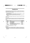
The IAEA does not normally maintain stocks of reports in this series.
However, microfiche copies of these reports can be obtained from
IN IS Clearinghouse
International Atomic Energy Agency
Wagramerstrasse 5
P.O. Box 100
A-1400 Vienna, Austria
Orders should be accompanied by prepayment of Austrian Schillings 100,
in the form of a cheque or in the form of IAEA microfiche service coupons
which may be ordered separately from the I MIS Clearinghouse.
The originating Section of this publication in the IAEA was
Physics Section
International Atomic Energy Agency
Wagramerstrasse 5
PO Box 100
A-1400 Vienna, Austria
MANUAL FOR TROUBLESHOOTING AND UPGRADING OF NEUTRON GENERATORS
IAEA, VIENNA, 1996
IAEA-TECDOC-913
ISSN 1011-4289
© IAEA, 1996
Printed by the IAEA in Austria
November 1996
FOREWORD
During the past 20-25 years the IAEA has provided many new laboratories in the
developing world with simple low voltage accelerators for the production of neutrons via the
well known 2H(d,n)3He and 3H(d,n)4He reactions. (These neutron generators were originally
supplied mainly for purposes of neutron activation analysis). However, the operation of
these machines can often be halted or compromised by a lack of special or short lifetime
components. Serious problems can also arise when the original well-trained technical staff
leave the laboratories and when the new operators have less experience in accelerator
technology.
This manual is intended to assist operators in troubleshooting and upgrading of
neutron generators. It is directed particularly to operators and technicians in less experienced
laboratories and therefore the descriptions of the principles and techniques of these machines
are operator oriented. In addition to a discussion of the main characteristics of neutron
generators, detailed information is given on the function of particular commercial units, on
common problems related to specific components of accelerators, and on methods of
troubleshooting and repair. Detailed schematic and circuit diagrams are provided to help
operators in the development and improvement of the generators.
The problems treated in the Manual have been collected during several IAEA missions
in developing countries.
The IAEA is grateful to T. Sztaricskai, who performed the major part of the drafting
of the manuscript, and also to J. Csikai and S. Szegedi for their contribution to the drafting.
The IAEA officer responsible for this publication was R.L. Walsh, Physics Section, Division
of Physical and Chemical Sciences.
EDITORIAL NOTE
In preparing this publication for press, staff of the IAEA have made up the pages from the
original manuscripts as submitted by the authors. The views expressed do not necessarily reflect those
of the governments of the nominating Member States or of the nominating organizations.
Throughout the text names of Member States are retained as they -were when the text was
compiled.
The use of particular designations of countries or territories does not imply any judgement by
the publisher, the IAEA, as to the legal status of such countries or territories, of their authorities and
institutions or of the delimitation of their boundaries.
The mention of names of specific companies or products (whether or not indicated as registered)
does not imply any intention to infringe proprietary rights, nor should it be construed as an
endorsement or recommendation on the part of the IAEA.
The authors are responsible for having obtained the necessary permission for the IAEA to
reproduce, translate or use material from sources already protected by copyrights.
CONTENTS
1. INTRODUCTION .............................................................................
9
2. PRINCIPLES OF OPERATION ............................................................
11
3. DETERMINATION OF THE BEAM ENERGY .......................................
23
4. TYPES OF NEUTRON GENERATORS ................................................. 26
4.1. Commerical neutron generators ...................................................... 28
4.2. Sealed tube neutron generators ....................................................... 34
4.3. Intense neutron generators ............................................................ 38
5. ION SOURCES: OPERATION PRINCIPLES, MAINTENANCE
AND TROUBLESHOOTING ...............................................................
5.1.
5.2.
5.3.
5.4.
43
High frequency ion sources ...........................................................
Extraction of ions from ion sources ................................................
Maintenance of gas discharge pyrex bottle ........................................
High frequency oscillators ............................................................
5.4.1. Troubleshooting of high frequency oscillators ...........................
5.5. Penning ion sources ....................................................................
5.5.1. Troubleshooting of Penning ion sources ..................................
43
48
51
52
55
58
61
6. DEUTERIUM LEAKS .......................................................................
63
6.1. The palladium leak .....................................................................
6.2. The thermomechanical leak and the needle valve ................................
6.2.1. The thermomechanical leak valve ..........................................
6.2.2. Maintenance and troubleshooting of thermomechanical leaks ........
6.2.3. Needle valves ..................................................................
6.2.4. Maintenance of needle valves ...............................................
6.3. Calibration of leak valves: Gas consumption measurements of ion sources
6.3.1. Measurement ...................................................................
63
65
65
66
67
70
73
74
7. DEUTERIUM ELECTROLYZERS ........................................................
76
7.1. The float regulator electrolyzer ......................................................
80
8. REMOTE CONTROL OF THE HIGH VOLTAGE TERMINAL ...................
84
8.1.
8.2.
8.3.
8.4.
8.5.
Mechanical control .....................................................................
Electromechanical control .............................................................
Insulation transformer control ........................................................
Optical insulation control ..............................................................
Computer control .......................................................................
84
85
86
88
88
9. VACUUM SYSTEMS OF NEUTRON GENERATORS ..............................
93
9.1. Important terms and units in vacuum technology ................................ 93
9.1.1. Terms ............................................................................ 93
9.1.2. Units ............................................................................. 99
9.2. Vacuum pumps ..........................................................................
9.2.1. Vacuum system based on a combination of
oil diffusion and rotary pumps .............................................
(a) The rotary vane pump ..................................................
(b) The diffusion pump ......................................................
(c) Combination of diffusion and rotary pump .........................
9.2.2. Vacuum system based on Ti-ion getter pump ...........................
9.2.3. Vacuum system based on turbomolecular pump ........................
9.3. Pressure (vacuum) measurements ....................................................
9.3.1. Thermal conductivity gauges ................................................
9.3.2. lonization gauges ..............................................................
(a) Thermionic ionization gauges .........................................
(b) Cold cathode or Penning ionization gauge ..........................
9.4. Pressure monitoring and leak detection ............................................
9.4.1. Leak rate measurement .......................................................
9.4.2. Pumping speed measurement ...............................................
9.4.3. Leak detection .................................................................
100
102
102
104
106
Ill
113
115
115
116
116
117
118
118
119
123
10. BEAM ACCELERATION AND BEAM TRANSPORT SYSTEMS ................ 128
10.1.
10.2.
10.3.
10.4.
10.5.
Electrostatic lens ......................................................................
Unipotential or Einzel lens ..........................................................
Troubleshooting of electrostatic focus lenses ....................................
The acceleration tube .................................................................
Troubleshooting of acceleration tubes .............................................
128
129
130
131
134
11. PRINCIPLES OF BEAM FILTERS ....................................................... 135
11.1.
11.2.
11.3.
11.4.
11.5.
Electrostatic and magnetic beam deflection ......................................
Troubleshooting of electrostatic deflectors .......................................
Analyzing magnets of neutron generators ........................................
Vacuum chambers of deflecting magnets .........................................
Problems with analyzing magnets ..................................................
135
137
138
144
145
12. QUADRUPOLE LENSES ................................................................... 146
12.1. The biased quadrupole lens ......................................................... 148
12.2. The biased magnetic quadrupole doublet ......................................... 150
12.3. Troubleshooting of a magnetic quadrupole lens ................................. 154
13. HIGH VOLTAGE POWER SUPPLIES .................................................. 155
13.1. Electrostatic (Felici) high voltage generator .....................................
13.2. AC-DC conversion high voltage power supplies ...............................
13.2.1. The single phase half wave rectifier ....................................
13.2.2. Cascade generators .........................................................
13.2.3. Improved cascade circuits ................................................
13.3. Troublehsooting of high voltage power supplies ................................
155
159
159
161
164
168
14. BEAM LINE COMPONENTS ............................................................. 173
14.1. Beam stops ............................................................................. 173
14.2. Beam scanners ......................................................................... 173
14.3. Wire electrode (matrix) beam scanners ........................................... 178
14.4.
14.5.
The Faraday cup ......................................................................
14.4.1. Beam current integration ..................................................
Target assemblies .....................................................................
14.5.1. Target replacement .........................................................
14.5.2. Air cooled target holder ..................................................
14.5.3. Replacement of the target at air cooled target holders ..............
14.5.4. Rotating and wobbling target holders ..................................
179
182
182
185
188
188
191
15. CLOSED CIRCUIT COOLING SYSTEMS ............................................. 192
15.1.
15.2.
The Kaman cooling system .......................................................... 192
15.1.1. Maintenance ................................................................. 193
Closed circuit cooling system with soil heat exchanger ....................... 195
16. PNEUMATIC SAMPLE TRANSFER SYSTEMS ...................................... 197
17. NANOSECOND PULSED NEUTRON GENERATORS .............................. 200
17.1.
17.2.
Pre-acceleration nanosecond bunched ion beam neutron generator .......... 200
Post-acceleration klystron bunching of a commercial neutron generator ... 204
18. THE ASSOCIATED PARTICLE METHOD ............................................ 206
18.1.
Self-target formation by deuteron drive-in ....................................... 208
19. NEUTRON MONITORS ..................................................................... 211
19.1.
Monitoring by long counter ......................................................... 211
19.2.
Fission chamber monitoring ......................................................... 212
20. SAFETY: HAZARDS RELATED TO NEUTRON GENERATORS ............... 215
20.1.
20.2.
20.3.
20.4.
20.5.
20.6.
Radiation hazard .......................................................................
Radioactive material storage and waste disposal hazard .......................
High voltage hazard ..................................................................
Implosion hazard ......................................................................
Pressure hazard ........................................................................
Fire hazard .............................................................................
215
219
219
220
220
220
21. CONSTRUCTION OF A NEUTRON GENERATOR LABORATORY ........... 221
21.1.
21.2.
21.3.
Construction details ................................................................... 221
Workshops .............................................................................. 223
Laboratory log book .................................................................. 224
REFERENCES ....................................................................................... 227
ANNEX A: LIST OF MANUFACTURERS AND COMPONENT DEALERS ....... 233
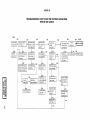
ANNEX B: TROUBLESHOOTING FLOW CHART FOR NEUTRON
GENERATORS WITH RF ION SOURCE .................................... 241
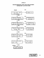
ANNEX C: TROUBLESHOOTING FLOW CHART FOR SEALED
TUBE NEUTRON GENERATORS ............................................ 243
ANNEX D: TROUBLESHOOTING FLOW CHART FOR NEUTRON
GENERATOR VACUUM SYSTEM ......................................... 245
CONTRIBUTORS TO DRAFTING AND REVIEW ......................................... 247
1. INTRODUCTION
Neutron generators are small accelerators consisting of vacuum, magnetic,
electrical and mechanical
components,
radiation sources,
cooling circuits and
pneumatic transfer systems. There are various types of ion sources, beam accelerating and transport systems, targets, high voltage and other power supplies, neutron and tritium monitors and shielding arrangements.
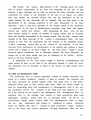
The operation, maintenance and troubleshooting of a neutron generator require
well trained technicians who can successfully undertake not only preventive maintenance of the machine but also its upgrading.
Troubleshooting and the locating of faults in components can be just as
difficult as their prevention. Thoughtless component exchange in an accelerator
may cause additional problems: the correct choice of component for a given function in the machine requires complete understanding of the operation of the generator as well as the role of the component in the machine.
In troubleshooting
for neutron generators, as with other sophisticated
equipment, it may be that the cause of malfunction stems from a single fault and
that an investigation of the whole system is both time consuming and unnecessary.
However, an electrical failure in the high voltage power supply or a discharge in
the accelerating tube could be caused by trouble in the high vacuum system. An
experienced troubleshooter can avoid unnecessary investigation of a number of
subunits.
This Manual has been prepared not only for operators but also for those who
are dealing experimentally with the upgrading of neutron generator laboratories.
Principles of operation and output characteristics of neutron generators can be
found in Refs [1-3]. This Manual is restricted to practical information required
by the operator and service personnel. The functions of the subunits are described and proposals for troubleshooting in case of malfunction of a component
are outlined. The Manual contains descriptions of some symptoms and proposals for
their repair. The proposed repair and maintenance methods have been chosen bearing in mind that some laboratories may have poor infrastructure.
The Manual contains a short description of the commercially available neu
Iron generators, including the sealed tube and intense models. The description of
the operation of a specific component is usually followed by a general guide to
troubleshooting and repair. As this is NOT A SERVICE MANUAL, the guidelines for
troubleshooting and maintenance are not given for all types of neutron generator,
although the information herein can be used for any type of low voltage accelerator. The detailed description of some methods, such as pulsing or the associated
particle technique, is intended to help in improving and widening the applica-
tions of the original machine. The list of manufacturers and other sources of
components in Annex A is intended to assist laboratories in developing countries
to find suppliers for spare parts or improved components. The short review of the
hazards related to accelerators is particularly directed towards operators who
have less experience in these matters and should be read with care by them. The
detailed schematic and workshop drawings should be useful in upgrading neutron
generators and accelerators as well in setting up new experiments.
10
2. PRINCIPLES OF OPERATION
The low voltage (a few 100 kV) neutron generators produce neutrons by the
following reactions:
2
3
H(d,n)3He
Q= 3.268 MeV
(1)
H(d,n)4He
Q = 17.588 MeV
(2)
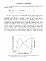
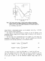
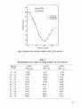
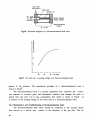
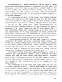
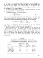
The large cross section of the 3H(d,n) 4He reaction permits high yields of
fast neutrons to be obtained even at low deuteron energy (150-200 keV). The 0°
differential
cross
sections of reactions
(1) and (2) are 2.6 mb/sr and 400
mb/sr, respectively. The total cross section of the 3H(d,n) 4He
reaction has a
broad resonance with a maximum value of 5 barns at E, = 107 keV. At this deuteron energy the total cross section of the
H(d,n) He reaction is about 20 mb;
therefore, the contribution of the D-D background neutrons to those emitted in
the D-T reaction can be neglected. As the D-T cross section has a peak at around
107 keV, and the
tritium
targets are thick
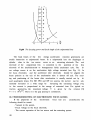
metal titrides, the neutron yield
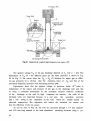
shows an increasing trend up to about 400 keV bombarding energy (see Fig.l). The
D-D reaction is used for neutron production mainly by
electrostatic accelerators or cyclotrons, where the neutron energy is changed by changing the deuteron
100
200
300
DEUTERON ENERGY (keV)
Fig.l Neutron production cross section and the total yield of neutrons for a
TijT, , thick target vs deuteron energy
11
i r
150-
• Meos by Zr/ Nb
'—£
Calc
—— Calc.
- tt.5-
0.15
Ed(keV]
14.0
0.1
13.5-
30
60
90
120
150
180
EMISSION ANGLE
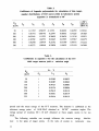
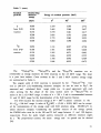
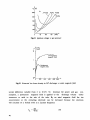
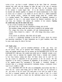
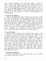
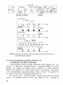
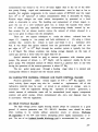
Fig.2 Thick target neutron energy vs emission angle at different bombarding
deuteron energies. The angular dependence of the neutron energy spread
relates to E, = 150 keV. The energy broadening of D-T plasma neutrons at
T.= 10 keV [6], is also shown
energy. However, monoenergetic neutrons can be produced only at Ed < 4.45 MeV,
below the deuteron break-up threshold.
The energy of the emitted neutrons in reactions (1) and (2) depends on the
bombarding deuteron energy and the emission angle of neutrons to the direction of
the deuteron beam.
The thin target data recommended [4] for the angular (Yn) and energy (En)
distributions of neutrons emitted in the D-D and D-T reactions can be well approximated by the following expressions [1, 6] in laboratory system:
Y
n<V>
=
(3)
(4)
In eqs (3) and (4), n = 5 and 3 for D-D while n = 3 and 2 for D-T reac
tions. The evaluated data [5] for thick targets can also be described by eqs (3)
and (4). The values of the Y , Y^ EQ and Ej coefficients from a least-squares
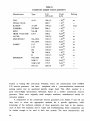
fit are given in Tables 1-5 for the 20-500 keV deuteron energy range [1,6]. In
12
the case of the D-T reaction, eqs (3) and (4) have been checked by experiment
using a point source in a scattering-free arrangement [1] and the Zr/Nb, Zr/Au,
Zr/Ta activity ratio method [7,8]. The En(Ed,0) functions at
Ed = 50, 150 and
300 keV for a thick tritium target are shown in Fig.2.
Table 1.
Recommended parameter values for calculation of thin target
angular distributions of D-T source yields in laboratory system
(equation 3) normalized to 90°
Ed(keV)
A
A
20
30
40
50
60
70
100
150
200
250
300
350
400
450
500
1
1
1
1
1
1
1
1
1
1
1
1
1
1
1
0.0220
0.0227
0.0310
0.0344
0.0518
0.0407
0.0482
0.0599
0.0678
0.0685
0.0818
0.0904
0.1003
0.1140
0.1273
o
l
*2
0.00025
-0.0093
0.0007
0.0010
-0.0035
0.0011
0.0011
0.0009
0.0005
-0.0104
0.0005
0.0028
-0.0008
-0.0101
-0.0187
o (90°)
(mb/sr)
[Ref.4]
4.2942
19.6126
52.8382
105.4180
173.2630
249.3768
393.3834
316.3704
198.4180
132.8133
95.0878
77.3864
63.4112
53.0290
45.5970
Data obtained from the 89rZr/ /92mmNb
above activity ratio [6] produced in
(n,2n) reactions prove the possible use of
the analytical expressions.
The calculated energy spread (6E ) [6] of neutrons (1/2 FWHM) as a function of emission
angle for a thick TiT target is also shown in Fig.2 at E j = 150 keV.
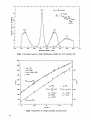
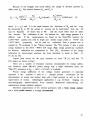
Typical
shapes of the distributions [9] calculated by the
Monte Carlo simulation code
PROFIL [10] are shown in Fig.3.
The
neutron energy spreads refer
to the following
circumstances:
+
E, = (190±10)keV, point-like beam spot, D analyzed beam, 11.5 cm sample-target
distance, and 8 mm x 16 mm sample dimension. Recently, Kudo and Kinoshito [11]
have developed a method based on the pulse height distribution of the recoil edge
for 4He nuclei in a 3He proportional counter for the determination of the energy
13
Table 2.
Coefficients of Legendre polynominals for calculation of thin target,
angular distributions of D-D source yields in laboratory system
(equation 3) normalized to 90°
E
a (90°)
d
(keV)
A
A
50
100
200
300
400
500
I
1
1
1
1
1
0.11787
0.01741
-0.03149
-0.10702
0.02546
-0.10272
o
l
*2
*3
0.58355 -0.11353
0.88746
0.22497
1.11225
0.38659
1.64553
0.63645
1.05439
0.21072
1.09948
0.29820
A
A
4
5
0.04222
0.08183
0.26676
0.67655
0.81789
1.09435
0.16359
0.37225
0.11518
0.35367
0.59571
0.76159
(mb/sr)
[Ref.4]
0.32016
1.01828
1.95031
2.66479
3.32222
3.63084
Table 3.
Coefficients in equation 3 for the calculation of the D-T
thick target neutron yield vs emission angle
F
fi.j
(keV)
50
100
150
200
250
300
325
D-T
—————————————————————
A
o
1
1
1
1
1
1
1
A
l
0.03003
0.04087
0.04727
0.05124
0.05419
0.05651
0.05616
A
2
0.00035
0.00062
0.00083
0.00096
0.00110
0.00119
0.00119
spread and the mean energy of the D-T neutrons. The detector is calibrated at the
reference energy point of 14.00 MeV obtained at 96°-98° emission angles. The
energy spread of neutrons <5E ^ 10 keV obtained at these angles seems to be too
small.
The following variables can strongly influence the neutron energy
distribution: 1) the types of target atoms, 2) the ratio of atomic to molecular ions,
14
Table 4.
Values of parameters in equation 4 for the calculation of thin target
neutron energy vs emission angle in laboratory system
E
d
(keV)
50
100
200
300
400
500
D -T
E
o
14.04814
14.06732
14.10711
14.14704
14.18670
14.22569
E
l
0.47679
0.67488
0.95596
1.17282
1.35640
1.51899
D -D
E
E
E
o
2
0.00834
0.01719
0.03320
0.04923
0.06527
0.08249
2.46073
2.47303
2.49771
2.52289
2.54798
2.57246
E
l
0.24848
0.35237
0.50072
0.61581
0.71456
0.80285
E
2
0.01282
0.02524
0.05044
0.07530
0.10013
0.12592
3
0.00031
0.00062
0.00242
0.00589
0.00757
0.01024
Table 5.
Values of parameters in equation 4 for the
calculation of thick target neutron energy vs
emission angle in laboratory system
E
d
(keV)
50
100
150
200
250
300
325
400
500
D -D
D -T
E
o
E
l
E
2
14.06520 0.42329 0.00682
14.07883 0.57613 0.01222
14.08942 0.66776 0.01600
14.09680 0.72427 0.01908
14.10286 0.76661 0.02167
14.10803 0.80001 0.02374
14.10723 0.79477 0.02347
_
_
.
E
o
E
l
.
2.46674 0.30083
2.47685 0.39111
2.49712 0.47697
2.50981 0.55825
2.52140 0.62147
_
E
2
_
0.01368
0.04098
0.05124
0.07125
0.09816
E
3
-
0.02749
0.02957
0.02474
0.03307
15
I
13.2
13.*.
13.6 13.8
I———I—I—I—
14.0 14.2 14.4 14.6 14.8 15.0 15.
NEUTRON ENERGY [ MeV]
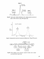
Fig.3 Calculated neutron energy distribution profiles for D-T reaction [9]
exp. IRK
x exp. CBNM
• eval. ( Pavlik, 1989)
fitted
90
Zr(n.2n) 8 9 Zr x l X
ff(E
100 -
52
n ) = VQ1En
Cr(n.2n) 51 Cr
15
13
Fig.4 Parameters of energy standard reactions [12]
16
3.0
Ed = 200 keV
O)
z:
50
2.5
o
or
30
2.0 10
30
I
I
I
60
90
120
EMISSION ANGLE [9]
I
150
180
Fig.5 Neutron energy vs emission angle for D-D reaction at E, = 200 keV
3) the energy spread of ions, 4) the slowing down and
scattering of projectiles
in the target. Therefore, a value of (14.00 ± 0.07) MeV at 96°-98° is recommended
as a reference for absolute normalization of the energy scale with D-T neutrons.
Shapes and parameters of the cr(En) curves for 90Zr(n,2n)89Zr and 52Cr(n,2n)51Cr
energy standards given in Ref. [12] are shown in Fig. 4. A value of (460 ± 5)mb
is recommended for the cross section of the 93Nb(n,2n)92mNb fluence monitor
around 14 MeV.
The error of this method is determined by the shapes of the 90Zr(n,2n) or
the
Cr(n,2n) cross section curves and the source-sample geometry, but it does
not exceed 50 keV, while the sensitivity between 13 and 15 MeV is, on average,
50 %/MeV and 64 %/MeV for Zr and Cr, respectively. The activity ratio is measured
with an accuracy of better than 1 % and so the error in the determination of the
mean neutron energy at 14.1 MeV is about 20 keV.
This method is also applied to determine the mean neutron energy for an
extended sample. In this case the Zr and Nb foils are placed back-to-back in
different positions inside the sample.
The calculated energy-angle functions En(0) for D-D reaction are shown in
Fig.5 for thin and thick targets at E, = 200 keV.
17
The measurements of the mean energy and its spread require appropriate energy and fluence monitors. The angular yield of the D-D neutrons can be measured
either by the 238U(n,f) using a depleted U layer in a fission chamber or by the
115
In(n,n')115mIn reaction. The a r(E ) curve is relatively well known [13] and
its change between 2 and 3 MeV is within 2.0 % (see Fig.6). For 115In(n,n')115mIn
reaction, the high cross section value in this
energy
range is advantageous;
however, this inelastic process is sensitive for the scattered neutrons.
Measurements carried out in Debrecen, Jiilich, Dhaka and Khartoum have indirated that the discrepancies in the a(E ) data between 2 and 3 MeV originate
mainly from the presence of room scattered neutrons and self-target build-up in
beam apertures. The contamination of the neutron spectrum by the scattered neutrons can be decreased if a scattering-free arrangement is used. The contribution
of the scattered neutrons to the activity can be checked [14] via the
1/r2 relation between the apparent activity and the flux values.
EMISSION ANGLE [9]
50
100
T
150
500
1.00
6 ( 90*)
at E,a = 2 0 0 k e V
JO
e
400
0.95
238
300
1.0
U (n,f
i——i——i——I
I
2.0
3.0
i
U.Q
NEUTRON ENERGY [ MeV ]
Fig.6 Absolute and relative cross section curves for the 238U(n,f) reaction
between the threshold and 14 MeV neutron energy
18
2.4
2.2
D(d,n) He
E.=200keV
a
O
measured
eye-guide
—— calculated
2.0
>s
V
J3
Q>
ce
1.4
1.2
i.o
0.8 LJ-
50
100
150
Emission angle
Fig.7 Measured and calculated angular yields of D-D neutrons
Table 6.
Recommended cross sections of energy monitors for D-D neutrons
Neutron
e nergy
1.9
2.0
2.1
2.2
2.3
2.4
2.5
2.6
2.7
2.8
2.9
-
2.0
2.1
2.2
2.3
2.4
2.5
2.6
2.7
2.8
2.9
3.0
a(mb)
Zn(n,p)
a(mb)
Ni(n,p)
M
58
6.095
8.635
11.65
15.82
20.14
26.77
34.36
43.10
54.70
66.45
78.80
36.8
46.28
60.12
73.95
87.79
101.6
117.1
134.3
151.6
168.8
186.0
a(mb)
P(n,p)
31
8.353
9.338
14.57
24.04
31.86
38.02
46.50
57.30
62.52
62.17
61.49
19
Table 7.
Energies of residual particles emitted in
T(d,n)4He, D(d,n)3He, and D(d,p)3H reactions
Residual
particles
Bombarding
deuteron
energy
(MeV)
Energy of residual particles (MeV)
0°
180°
n
from D-T
reaction
0.050
0.100
0.150
0.200
0.250
0.300
14.554
14.783
14.960
15.117
15.259
15.390
14.068
14.088
14.108
14.128
14.148
14.167
13.599
13.432
13.304
13.203
13.117
13.042
n
from D-D
reaction
0.050
0.100
0.150
0.200
0.250
0.300
2.723
2.852
2.958
3.052
3.139
3.220
2.462
2.474
2.486
2.498
2.511
2.524
2.225
2.146
2.090
2.045
2.009
1.978
0.050
0.100
0.150
0.200
0.250
0.300
4.041
4.261
4.436
4.587
4.723
4.848
3.531
3.520
3.551
3.501
3.491
3.481
3.086
2.910
2.779
2.672
2.581
2.499
0.050
0.100
0.150
0.200
0.250
0.300
1.093
1.223
1.329
1.423
1.510
1.591
0.807
0.795
0.782
0.769
0.757
0.745
0.596
0.516
0.460
0.416
0.380
0.349
4
He
from D-T
reaction
3
He
from D-D
20
90°
Table 7. (cont.)
Residual
particles
Bombarding
deuteron
energy
(MeV)
P
from D-D
reaction
3
H
from D-D
reaction
Energy of residual particles (MeV)
0°
90°
180°
0.050
0.100
0.150
0.200
0.250
0.300
3.324
3.465
3.579
3.681
3.773
3.860
3.036
3.048
3.061
3.073
3.085
3.098
2.772
2.657
2.617
2.566
2.523
2.486
0.050
0.100
0.150
0.200
0.250
0.300
1.311
1.451
1.565
1.666
1.758
1.844
0.997
0.984
0.971
0.959
0.946
0.933
0.758
0.668
0.603
0.552
0.509
0.472
64
58
The
Zn(n,p)64Cu,
Ni(n,p)58Co and the 31P(n,p)31Si reactions are recommended as energy monitors for D-D neutrons in the 2-3 MeV range. The latter
is a pure beta emitter. Cross sections in the 2 and 3 MeV neutron energy range
are summarized in Table 6.
The angular yield of D-D neutrons is measured by the 115In(n,n')115mIn reaction at 200 keV [15] bombarding deuteron energies. As can be seen in Fig.7, the
measured and calculated thick target yields are in good agreement with each
other, proving the flat shape of the cross section curve of 115In(n,n')115mIn reaction in the 2.1-2.9 MeV range. A value of a = 325 ± 5 mb is recommended between
2.1 and 2.9 MeV range for the determination of the D-D neutron fluence.
For D-D reaction the neutron energy at & = 100° is almost constant in the
50 ^ Ed ^ 500 keV range. A value of En(100°) = (2.414 ± 0.010) MeV can be accept
ed for normalization of the energy scale with D-D neutrons using 100-200 keV incident deuteron energies. Considering the possible sources of the energy spread,
the FWHM value must be in the 100 and 25 keV range between 0 and 100 degrees,
respectively. From the pulse height spectra measured at different emission angles
by a 3He proportional counter, the mean energy and its spread can be derived
[16].
21
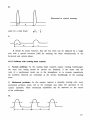
The absolute source strength of the 3H(d,n)4 He and 2H(d,n)3 He reactions can
be measured accurately (<0.5%) by means of the associated particle method (APM),
i.e. by the registration of the He and He particles from the D-T and D-D reactions, respectively, by an alpha detector in a given solid angle.
The differential cross sections of the 2H(d,n)3He and 2H(d,p)3H reactions
are the same at 90° up to a few 100 keV deuteron energies [17]. Therefore, the
source strength can be determined by observing the recoil tritons or protons with
a silicon surface barrier detector. In Table 7 energies of the residual particles
produced in the D-T and D-D reactions are summarized.
In addition to the 93Nb(n,2n), the 27Al(n,a) activation detector is also a
good fluence monitor for D-T neutrons. Fission chambers with
U and
"Th
foils, long counters and liquid scintillators are used as prompt monitors for recording the source strength as a function of time.
The spectra of background neutrons are determined either by the activation
threshold foils method or by prompt spectrometry based for example on an NE-213
liquid scintillator.
The ideal 14 MeV neutron field of the neutron generators is contaminated in
practice by lower energy groups to some extent. The most important sources of
these non-14 MeV neutrons are:
1) Elastic and inelastic scattering of the original 14 MeV neutrons in the target
target assembly, sample holders, bulk samples, APM head and electronics, air,
construction materials of the target room.
2) The D + D neutrons from the drive-in target, resulting in a 0.1-1% of the
D-T yield depending on the condition of the tritium target.
3) D + D neutrons from the beam apertures (i.e. beam accelerating and transport
systems, diaphragms, etc.).
4) Contribution of the D~ and D.,
ion induced reactions in the case of nonanalyzed beam.
In order to decrease the influence of these parasitic neutrons, the target
should be placed in the center of the target room at equal distances from the
walls, floor and ceiling. Thin wall, air cooled target holders [1] are ideal to
get low contributions of the background neutrons. The thick, water cooled targets
in a heavy-set target holder and the mixed beam neutron generators (i.e. sealed
tubes) may produce a contaminant of non-14 MeV neutrons of about 10%.
22
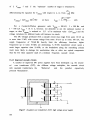
3. DETERMINATION OF THE BEAM ENERGY
According to eqs (3) and (4) the angular yield and energy of neutrons depend
on the incident deuteron energy.
The absolute energy of an ion beam can be measured by using an electrostatic, a 180° magnetic or a velocity analyzer. In addition to the absolute methods,
the energy calibration of particle
accelerators is usually performed
by a 90°
magnetic analyzer which must be calibrated with nuclear reactions having accurately known resonance and threshold energies.
A magnetic analyzer containing entrance and exit slits is transparent only
for ions with charge Q and energy E
E = Kf2Q2/m
(5)
where K is the analyzing magnet calibration factor, f is the NMR frequency if the
strength of the magnetic field is measured by a nuclear-magnetic-resonance probe
(usually a proton probe) and E is the nonrelativistic kinetic energy [18], i.e
the analyzer is a tool for Q/m separation and for measuring the energy E.
In addition to the absolute methods, measurements of current through a bank
of resistors is widely used - because of its simplicity - below a few hundred kV
terminal
voltage. However, at high voltage, discharges on the surface of the
resistors and their unstable values can cause an uncertainty of about ± 5 kV.
During the last decades, new methods based on nuclear reactions have been
developed for precise beam energy measurement. For instance, by using a Ge(Li)
detector to measure the energy of the direct capture gammas emitted in the
12
C(p,y)13N non-resonant reaction, the absolute proton beam energy between 150
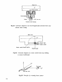
and 350 keV could be determined with a precision of about 0.4 keV [19]. The absolute energy calibration is possible even below 100 keV by using the D(p,y)3He
nonresonant reaction [20]. This process was observed [21] as low as
E = 25 keV. The Q values of the D(p,y)3He, 12C(p,y)13N and 16O(p,y)17F are
5.4936, 1.9435 and 0.60035 MeV, respectively. The nonresonant direct capture
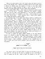
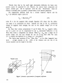
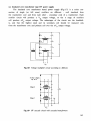
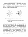
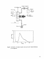
method has been developed [22] in an experimental arrangement as shown in Fig.8.
The y-ray yield curves are measured at target location 1 with a Nal(Tl)
detector. At the second location, the y-ray transitions can be measured with a
high resolution Ge detector at 0 and 90 degrees. According to the kinematics of
an X(p,y)Y reaction, the energy of a gamma photon emitted by a nucleus decaying
at rest is
M
E
° =°
+E
x
23
TARGET LOCATION 1
TARGET LOCATION 2
.
72cm J Ge{Li)
DETECTOR
8x8cmNaI(TU
DETECTOR
Fig.8 Experimental setup for measuring proton beam energy via the y-ray
detection emitted in non-resonant (p,y) reactions
10
1.0
10"
11
10
-6
CO
-7
10
0.5
10 -9
C£.
,-10
10
459keV RES.
10'
/1
0.1
I
I
0.2
0.3
ill
0.4
I
0.5
0.6
0.0
I
0.7
EplMeV]
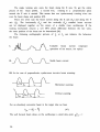
Fig.9 yield curves of (p,y) reactions on
24
B and
C
Because of the Doppler and recoil effects, the energy of detected gammas
differs from E \J . The relation between E\J and E3 is
#2.1/2
E2
E = E ii^LJ— _ ——° =
s
°
2M c 2
n
E
E 2 (MeV)
(1+£COS0) _ —o———— 0.53678 keV (7)
°
M (u)
where fi = v /c and 0 is the angle between the directions of M and the y-ray.
By measuring E at 90°, the energy of protons can be determined from eqs (6)
and (7). Equation (7) shows that at 90°, only the recoil effect must be taken
into account. The calibration of the Ge detector for high energy gammas is a
difficult
task. If the measurements are based on the D(p,y)3He reaction, the
6.12917 MeV gamma line with its single and double escape peaks at 5.61817 and
5.10717 MeV, respectively, can be used for calibration. Such a gamma line is
emitted by 16N produced in the 16O(n,p) reaction. The ^Ga isotope is also a good
energy standard in the 833.6 - 4807.0 keV range. High energy gamma-ray standards
for detector calibration are summarized in Ref. [23]. Procedure of the energy
calibration by non-resonant reactions has been described in detail in Refs
[1,
19, 20, 22, 24].
Typical yield curves for the (p,y) reactions on thick nB [1] and thin 12C
[25] targets are shown in Fig.9.
There are a number of resonance reactions recommended for energy calibration. However, below 200 keV proton energy only a single calibration point, the
n
B(p,y)12C resonance at E = (163.1 ± 0.2) keV, is available.
Precise energy calibration of low voltage neutron generators is especially
important if the
machine is used as a
charged particle
accelerator for the
determination of atomic and nuclear data with a high accuracy as well as for the
improvement of various
technological applications ( e.g. ion-beam
imaging, ion
microtomography, particle-induced X-ray emission, Rutherford backscattering, ion
implantation, prompt radiation analysis).
Therefore, improvement of the neutron generators with a beam energy analyzer
and a beam profile detector is strongly recommended.
d
25
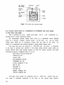
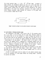
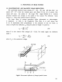
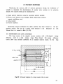
4. TYPES OF NEUTRON GENERATORS
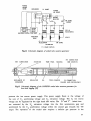
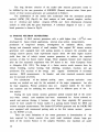
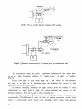
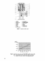
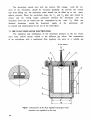
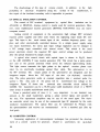
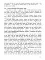
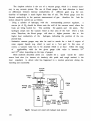
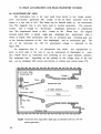
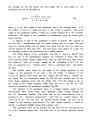
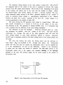
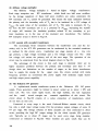
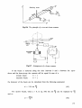
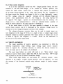
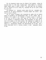
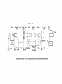
The principle of the neutron generator is shown in Fig. 10. This schematic
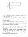
applies for all particle accelerator. A schematic drawing of a home-made generator working in Debrecen is shown in Fig. 11. From this figure it is easy to follow the functions of each unit and its position.
The
ion source, the
extraction, the
focusing, and the gas supply units
placed on the HV terminal need electric power, cooling and insulated remote
control systems. The ion source is RF or Penning type for standard (commercial or
medium size) neutron generators while it is a duoplasmatron (duopigatron) if
high currents are required. The deuterium gas flow is regulated into the ion
source by needle, thermomechanical or palladium leaks. As the ion beam analyzer
requires relatively
high power, the separation of the D beam is made usually
after acceleration.
The pulsing of the ion source allows the production of a pulsed beam, i.e.
14 MeV neutron burst, in the [is, range, while the nanosecond pulsing can be made
before and after acceleration using special bunching units.
The acceleration tube is generally a homogeneous field type allowing a high
pumping speed for the vacuum pumps situated at the ground potential. The intense
neutron generators (beam current over 10 mA) utilize strong focusing single-gap
or two and three gap tubes by which the space charge effects are taken into
account.
The
high voltage power supplies are usually Cockcroft-Walton voltage
multipliers,
Felici-type electrostatic machines, medium frequency Allibone-type
voltage
multipliers, insulated core transformer HV supplies or parallel powered
Dynamitron voltage multipliers.
In a number of commercial neutron generators, separate insulating transform-
ers are used to supply and control the HV terminal. These types are as follows:
SAMES J-15 and J-25, TMC A-lll and KAMAN 1254 models. Most of the non-commercial
neutron generators use a single insulating transformer or an insulated motor
driven generator (see Fig. 11), to ensure the power for the units placed on the
HV terminal. The control of these power supplies and other components like needle
valves can be performed by insulating electromechanically driven rods (MULTIVOLT,
KFKI and TOSHIBA neutron generators) or by insulated optical fibers (SAMES series
T neutron generators, INGE-1 in Dresden, RTNS-II at LLL, OCTAVIAN and FNS in Japan). The optical cables between the HV terminal and the control desk give the
computer control and regulation of the whole neutron generator.
Most neutron generators have ion beam handling facilities: magnetic or electrostatic quadrupole lenses, beam profile monitors, ion beam analyzers (simple
electromagnet or Wien-filter), beam stops and scanners, etc. The size and the
26
HV terminal
Ion source
Acceleration
Gas supply
Cooling
Power supplies
!____
, ,+ ,+ , + x
(d
,d 2 ,d 3 )
Ion beam
Beam handling
Lenses, ion
———— «=Beam analyzers
Pulsing.etc.
Target
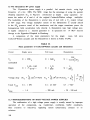
Suppr.Volt.
Cooling
3
H trap
—1
Accel. HV
Control
Insul.transf.
console
t
Vacuum
L_ _ _ _ _ _ _ _ and
cooling
systems
_,„____-_ J
Fig. 10 Block-diagram of neutron generator
HIGH
VOLTAGE TERMINA_L_
LIQUID H2
2QOkV
TRAP
DIRECT
TARGET -3QOV
CURRENT
SUPPRESSOR
-300V
^
300 kn
REGULATED MAINS
Fig. 11 Diagram of a working neutron generator
27
technical solution of the target holder depends on the purpose of the neutron
generator. A neutron generator utilized mainly for activation analysis, neutron
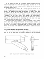
therapy or materials research may have a bulky water cooled target holder, especially for a few mA target current. The intense neutron generators, having several kW target loads, can manage this load only with water cooled rotating targets. The thin wall, low mass target holders with air jet cooling [1] are recommended for "clean" neutron work, around 2 and 14 MeV.
The vacuum system of a neutron generator consists of prepumps (mechanical,
cryogenic) and high vacuum (diffusion, ion getter, turbomolecular) pumps. The advantages of the diffusion pumps are as follows: low cost, high pumping speed
simple maintenance, long lifetime, no mobile components. Their disadvantages are:
oil vapour contamination of the accelerator components and the target which can
be decreased by using of FLOMBIN or SANTOVAC oils and liquid nitrogen traps
(see Fig. 11) not only at the inlet of the diffusion pump but also along the
beam lines.
The titanium getter pumps can assure clean vacuum and high pumping speed for
hydrogen (deuterium) gas; however, the high absorption rate for tritium released
from the target makes it difficult to handle the used pump elements because of
their high activity, even in the case of moderate commercial neutron generators.
The cleanest vacuum can be achieved by using turbomolecular pumps. Their disadvantages are the relatively high cost and the possibility of mechanical damage.
In general, Pirani and thermocouple vacuum gauges are used for measuring the
forevacuum. The high vacuum is measured mostly with Dushman type or Penning type
gauges. The use of the vacuum controllers makes possible the automation of the
neutron generator control. The rubber or Viton O-rings are changed these days
for metal gaskets: the contemporary neutron generators use bakeable vacuum components as well.
With neutron generators used for research purposes, control is mostly
manual, but the principle of minimal interlock and other control inputs is also
followed with commercial generators. The multipurpose and intense neutron generators use microcomputer and computer control systems. The choice of neutron generator depends on its construction and purpose.
This Manual outlines the commercial (medium), intense (high current) pulsed
and sealed tube neutron generators, dealing with their operation, technical solutions, maintenance and repair as well as with updating with a view to extending
their utilization in science and technology.
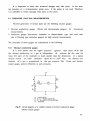
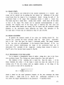
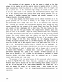
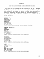
4.1 COMMERCIAL NEUTRON GENERATORS
The commercial neutron generators are modest machines with production yields
11
9
of about 10
28
n/s and 10 n/s for D-T and D-D reactions, respectively. They are
utilized in basic nuclear research, education
and technology, for measurement of
nuclear data, and in laboratory exercises to study the different interactions of
neutrons, detection of charged particles and neutrons. They are also used in accelerator technology for activation analysis, prompt radiation analysis,
irradiation effects of fast neutrons, neutron dosimetry, etc. Practically no technological development in the field of commercial neutron generators has been reported
in recent years and only a few companies are producing these moderate
(150-300 kV, 1-2 mA) machines.
The existing manufacturers are IRELEC (formerly AID and SAMES) in
France, KFKI in Hungary, the EFREMOV Institute in Russia, and MULTIVOLT in the
United Kingdom. The sealed tube replacement is still made by KAMAN NUCLEAR in the
USA.
These types of neutron generator are still in operation in many countries.
As these machines are excellent devices for pure and applied research, service
and education, the IAEA has provided them to the following developing countries:
Albania, Algeria, Bangladesh, Bolivia, Burma, Costa Rica, Cuba, Equador, Hungary,
Indonesia, the former Yugoslavia, Lebanon, Malaysia, Mongolia, Morocco, D.P.R. of
Korea, Nigeria, Pakistan, Peru, Singapore, Sudan, Thailand, Turkey, Zambia.
Unfortunately some of these generators are now out of order, and, in addition to
repair of the machines, it is recommended that they be fitted with some upgrading
components. For example, determination of the nuclear level schemes and neutron
cross sections requires microsecond and nanosecond pulsing units. These systems
have been developed almost entirely in the laboratories where the neutron generators were constructed and are not available commercially. Therefore, strong cooperation is required between the developing and advanced laboratories for upgrading the commercial neutron generators with pulsing units and other components.
As a number of manufacturers have closed down in the last decade, some "second
hand neutron generator" companies (POTENTIAL in the USA or MULTIVOLT in the UK)
have started to buy used machines and restore them to their original conditions.
POTENTIAL specializes in neutron generators manufactured by TEXAS NUCLEAR [29],
while MULTIVOLT deals with those made by SAMES. The lack of spare parts and
components causes many
problems for the users - especially in the industrially
less developed countries - in the field of maintenance and repair. Dealing with
"second hand neutron generators" is particularly
important for the developing
countries. Table 8 lists the most popular commercial neutron generators. Improvement of the original characteristics of a commercial neutron generator, i.e. analyzing magnet, quadrupole lenses, pulsing systems, associated target assemblies,
etc., needs local or international co-operation with experienced laboratories. An
excellent example of such international co-operation is the Fast Neutron Research
29
Table 8.
Commercial pumped neutron generators
Manufacturer
Type
U/I
[kV/mA]
Yield
[n/s]
TMC
TEXAS NUCL.
KAMAN
TOSHIBA
KFKI
HIGH VOLTAGE
ACCEL.
MULTIVOLT
A-lll
180/1.5
280/7
190/2.2
200/1
120/1.3
300/2
150/3.5
150/1.5
150/3.5
150/1.5
150/2.5
150/2.5
300/8
150/1.5
150/3
150/2
175/5
250/10
>1010
>10U
SAMES
EFREMOV
A- 1254
NT-200-5
NA-4B
LN-S
NA-150-2
NA- 150-4
J-15
J-25
JB
TB
D
NG- 150-1
NGP-11
NGP-11M
NG-12-1
>io
Pulsing
yUS
—
n
>1010
>io n
4xl010
3xl010
>1010
SxlO11
>1010
2xl010
2xlOU
~1012
5xl010
-1011
2xlOU
SxlO11
~1012
ns-/^s
—
—
—
fiS
ps
fis
JtS
A«s
//s
/IS
——
—
——
—
Facility at Chiang Mai University, Thailand, where the commercially built SAMES
J-25 neutron generator has been completed with a post-acceleration nanosecond
pulsing system and an associated particle target head. This effort resulted in a
good time-of-flight spectrometer laboratory based on a modest commercial neutron
generator. These were originally small compact machines, manufactured mainly for
activation analysis.
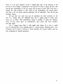
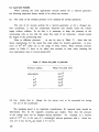
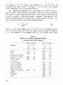
A comparision of the commercial neutron generators (see Tables 9 and 10) can
help users to select the appropriate machine for a specific application, while
knowledge of the technical solutions of these generators may help in the improvement of their own machines and in repair and troubleshooting. Some components can
be similar enough to be used in their own systems. The main characteristics and
30
Table 9.
Comparison of different commercial neutron generators
Type No.
10
>10
= io
n
1
+
S A M E S
TMC
2 3 4 5 6
Neutron yield [n/s]
+
+
+
12
<10
- 1012
KAMAN T* KFKI MULTIV. EFREMOV
7 8
9
10
11 12 13
+
+
+
+
+
+
+
+
+
+
Beam energy [keV]
<150
= 150 [keV]
<200
>200
>1
> 3
> 5
+
+
+
+
+
Electrostatic
+
Mains frequency
Medium frequency
Ins.transfor.
Ins.rod
Fiber optics
+
+
+
Penning
+
RF
Duoplasmatron
PD leak
Electrolyzer
Mechanical
Sealed tube
+
+
+
+
+
+
+
+
+
+
+
+
+
+
+
+
+
+
+
+
+
+
Beam current [mA]
+
+
++
+
+
+
Ion source
+
+ +
+
+ +
+
+
Gas supply
+
+
+
+
+
-I+
+
HV supply
+
+
+
+
+
+
+
+
+
+
+
+
+
+
+
+
Terminal control by
+
+ +
+
+
+
+
+
+
+
+
+
+
* TOSHIBA
31
Table 9. (cont.)
Type No.
1
S A M E S
TMC
2 3 4 5 6
KAMAN T
7 8
9
KFKI MULTIV. EFREMOV
10
11 12 13
Accel.tube
Homogeneous +
Inhomogeneous
Vacuum system
Diff.pump
+
Titan getter
+
Turbomolecular
Pneumatics
HV terminal insulation
Air
Oil
SF-6
+
+
solid
Cooling system
Open
Closed circuits
+
Power consumption
<2.5 kVA
>2.5 kVA
>4 kVA
>8 kVA
+
Optional pulsing
< 100 /<s
> 100 /«s
Beam stop
+
+
+
Spare parts
Easy
Available
Not easy
+
+
+
Maintenance of the machine
Comfortable
Not comfort.
TOSHIBA
32
+
+
Table 10. Advantages and limitations of the commercial neutron generators
TYPE
ADVANTAGES
DISADVANTAGES
SAMES-D
Simple construction
Simple insulation (oil)
Small room for installation
Electrostatic HV unit
Mixed beam
Not easy maintenance and
repair of HV terminal
Horizontal use only
SAMES-J
Easy maintenance
Reliable electropneumatic
safety system
Easy beam line assembling
Mixed beam
Unreliable and too numerous
insulating transformers
Electrostatic HV unit
SAMES-T
Easy maintenance and repair
Reliable electropneumatic
safety system
Electrostatic HV unit
Insulator shaft motor generator
Mixed ion beam
The maximum HV can be
achieved only in an environment
that is not humid
AC power at the HV terminal
SAMES-JB
Compactness
Small room for installation
Simple installation and
position change
Safe operation in humid or
low pressure atmosphere
Mixed ion beam
Not easy maintenance and
repair
Special tools
SAMES-TB
Compactness, small room for
installation
Simple position change
Safe operation in humidty
Mixed ion beam
Not easy dismantling, repair
and maintenance
Special tools
TMC A-lll
Compactness, easy achievement
of horizontal or vertical beam
Simple closed circuit cooling
Mixed ion beam
Not easy dismantling, repair
and maintenance
Unreliable needle valve
KAMAN A-1254 Compactness, small room for
installation
Simple position change
SF6 insulation FREON 113 cooling
Mixed ion beam
Unreliable needle valve
TOSHIBA
NT-200
Long life D2 supply
Compactness
200 kV acceleration voltage
Mixed ion beam
Unavailable spare parts
KFKI NA-4
Compactness
Long life D~ supply
Small room for installation
Mixed ion beam
Low acceleration voltage
(120 kV)
MULTIVOLT Compactness
NA-150
Availability of spare
parts and components
Mixed ion beam
Relatively low yield
High D2consumption
33
technical solutions are given in Table 9,
following manufacturers and types:
where the numbers
correspond to the
SAMES (D, J, T, JB, TB) Type No. 1, 2, 3, 4, 5
TMC (A-lll) Type No. 6
KAMAN (A-1254, A-711) Type No. 7,8
TOSHIBA (NT-200) Type No. 9
KFKI (NA-4) Type No. 10
MULTIVOLT (NA 150-02 and NA 150-04) Type No. 11,12
EFREMOV (NG-150 I) Type No. 13
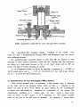
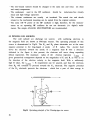
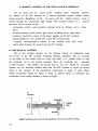
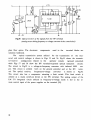
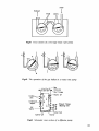
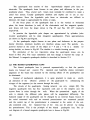
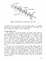
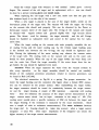
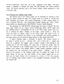
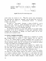
4.2 SEALED TUBE NEUTRON GENERATORS
The sealed tube neutron generators or neutron tubes are 14 MeV neutron sources used in in-situ geological
measurements
(bore-hole
logging), in hospitals
and in chemical, biological and industrial laboratories. Most neutron tubes have
a Penning ion source, a one- or two-gap acceleration section, a tritium target
and deuterium-tritium gas mixture filling system. The pressure of the gas is controlled by a built-in ion getter pump and/or gas storage replenisher. The tritium
displaced from the target during the operation is absorbed by the gas occlusion
elements and is accelerated later back into the target, resulting in an extended
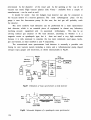
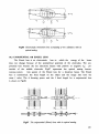
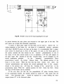
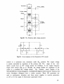
target life [26]. The operation principle of a typical sealed tube generator
is
shown in Fig. 12. The first sealed tube neutron generator was developed by PHILIPS
12
[27] and its originally low neutron yield could increase up to over 10 n/s. The
advantage of the neutron tubes is their small size which makes them suitable for
geological bore-hole logging or isocentric cancer therapy in hospitals. The disadvantages are their limited lifetime and the relatively high neutron production
cost. Typical applications of the neutron tubes (with built-in high voltage power
supplies and neutron detectors) are as follows: Bore-hole logging, deposit evaluation, uranium exploration and processing, mineral exploration, coal exploration
and processing,
oil well logging,
gas well logging, under-sea
exploration and
such utilization where the small diameter and the remote detection are important. For cancer therapy the isocentric irradiation is most important: the neutron source and the neutron collimator are rotated around the malignant tumour in
the same way as in linear accelerators or at radioactive sources.
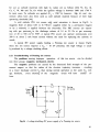
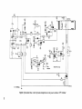
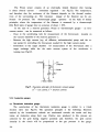
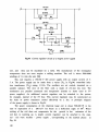
The deuteron ions - bombarding the tritium target - are produced in a Penning ion source. The ion source is powered by a 0 - 10 kV HV power supply consisting of an
insulating high voltage step-up transformer and single wave rectifier.
The discharge current of the ion source can be observed by an !<, ion source amp
meter. Owing to the negative resistance of gas discharges, a damping resistor
34
PENNING
VACUUM
GUAGE
REPLENISHER
TiT TARGET
PENNING
ION SOURCE
ION SOURCE
CURRENT
STEP-UP
TRANSFORMERS
PRESSURE CONTROL FEED BACK
VARIACS
ACCELERATION
EXTRACTION
ION SOURCE
H V POWER SUPPLIES
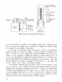
Fig.12 Schematic diagram of sealed tube neutron generator
VHV
CONNECTION
RESISTOR
TUBE TN26
HOUSING
HV CONNECTION
(IONSOURCE)
\
MECHANISM OF
EXPANSION
INSULATOR
OIL
TIME COUNTER
LV CONNECTION
(GAUGE AND R E S E R V O I R )
Fig.13 Schematic diagram of the SODERN sealed tube neutron generator for
bore-hole logging [28]
protects the ion source power supply. This power supply floats at the voltage of
the sum of U accelerating voltage and U extraction voltage. The U- ion source
+
+
•
•
voltage can be regulated by the right hand side variac. The D and T
mixed ions
are extracted by the U c extraction voltage into the first acceleration gap and
accelerated by the U acceleration voltage within the second gap towards the TiT
target. The operation of the sealed tube requires a definite gas pressure in the
35
tube. The gas pressure is regulated by heating the gas replenisher (mainly zircon
or titanium). The gas pressure is measured mainly by a Penning type vacuum meter.
Some sealed tube neutron generators utilize feedback control between the neutron
monitor and the replenisher to achieve a constant neutron yield.
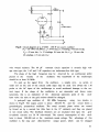
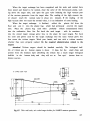
Sulphurhexafluoride (KAMAN 711), oil (several PHILIPS sealed tubes) or solid
plastic materials (SODERN tubes) are used for the insulation of the sealed tube
generator head [28].
The KAMAN 711 sealed tube is placed in a pressure vessel under the insulating compressed Sulphurhexafluoride gas. The ion source is cooled by electrically
insulating liquid FREON 113, while the target is cooled by circulated water outside the pressure tank. The arrangement makes it possible for the small so-called
accelerator head - which has only two pairs of coolant pipes and a couple of
cables - to be moved easily and adapt to the circumstances of the investigations.
This sealed tube neutron generator delivers over 10 n/s during its guaranteed
life-time of 200 hours.
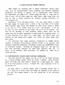
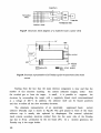
The PHILIPS sealed tube type 18601 has a built-in Dushman type ionization
vacuum gauge, a pressure regulating replenisher and a high voltage damping resistor in its 737 mm long, 70 mm diameter, usually oil filled, metal tube
container.
This typical
bore-hole logging neutron tube has a pulsing capability
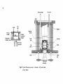
between 5 and 1000 ^s. A schematic diagram of a recent solid insulation tube
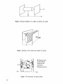
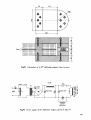
packed SODERN neutron generator is shown in Fig.13 [28].
Therapeutic use of neutron generators assumes a minimum 14 MeV neutron yield
of > 10 n/s. The relatively small size of the neutron tubes is an advantage in
fast neutron therapy: they can be easily installed in the neutron collimators of
the isocentric treatment geometry. The problems related to tritium handling in
pumped neutron generators do not exist in the case of the sealed tube, so sealed
tube intensive neutron generators are ideal for fast neutron cancer therapy. The
MARCONI-ELLIOTT [30] and the HAEFELY (the KARIN or KORONA) are sealed tube neutron generators that can meet the criteria of the high neutron yield and relatily long life-time. The MARCONI has a mixed D , T beam containing a refillable
sealed tube with typical high frequency ion source and a homogeneous field acceleration tube. The target material is Er, to achieve high thermal stability. The
manufacturer can renew the system, and this is advantageous for situations where
regular change of used sealed tubes is required. For cancer therapy, the sealed
tube in the collimator is changed regularly every week.
The KARIN tube is manufactured by HAEFELY in Basel. This generator has an
annular shaped Philips ion gauge (PIG) ion source at the ground potential, while
the cylindrical or conical target is on the high voltage potential and in the
36
ALPHA
SCINTILLATOR
-PHOTO MULTIPLIER
TUBE
D/T ION BEAM
ACCELERATING
ALPHA
PARTICLE
TUBE
ENVELOPE
HIGH VOLTAGE
INSULATOR
ELECTRODE
VACUUM
PINCH-OFF
HIGH VOLTAGE
ELECTRODES
TARGET
GETTER
-FARADAY
CAGE
-14MCV
NEUTRON
FOCUS
ELECTRODE
1C
SOURCE
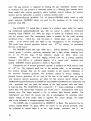
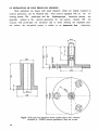
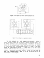
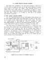
Fig. 14 A sealed tube neutron generator combined with APM head for
time correlated measurements
Table 11.
Comparison of sealed tube neutron generators
Type/Name Manufacturer
A-3045/6
A-3041-4
A-3043
18601
18604
TN-26
KARIN
TN-46
KAMAN
KAMAN
KAMAN
PHILIPS
PHILIPS
SODERN
MARCONI
HAEFELY
SODERN
Life-time
Acc.voltage/Beam current
[kV/mA]
200 h
2xl06 pulses
100 h
1000 h
400 h
2500 h
200 h
400 h
> 1000 h
200 kV/5 mA
125 kV/0.1 mA
200 kV/8 mA
125 kV/0.1 mA
200 kV/20 mA
200 kV/500 mA
225 kV/2 mA
Yield
[n/s]
3xl010
5xl07
5xl07
>108
>1012
2xl08
>1012
5xl012
>io n
center of the annular ion source and spherical collimator. A cylindrical
pneumatic rabbit system (sample transfer) can be introduced into the center of
the target along its axis by an insulating polyethylene tube to achieve a homogeneous
sample irradiation, especially if the sample is rotated during irradiation
in the hollow target. The conical targets are used almost only for neutron therapy. The target is produced from scandium titride. The tube can give > 1012 n/s
yield during its guaranteed life-time of 400 hours.
37
The long life-time criterion of the sealed tube neutron generators seems to
be fullfilled by the new generation of SODERN (France) neutron tubes. Some parameters of these neutron generators are summarized in Table. 11.
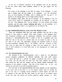
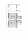
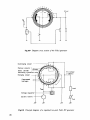
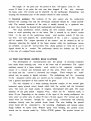
The combination of the sealed tube accelerator with the associated particle
method (APM) [28] (Fig. 14) for field analysis of bulk mineral samples, verification of chemical and nuclear weapons [29,30], and three dimensional elemental
analysis in solids [28] has great importance. A schematic diagram of such a combined generator is shown in Fig. 14.
4.3 INTENSE NEUTRON GENERATORS
Recently, 14 MeV neutron generators with a yield higher than > 1012 n/s were
developed for fusion related applications, neutron cross section measurements,
production of long-lived isotopes, investigations on radiation effects, cancer
therapy and elemental analysis of small samples. The original DC intense neutron
generators were equipped later with pulsing systems to measure the secondary and
leakage neutron spectra. Such experiments require about 100 times higher neutron
yields than that of today's intense neutron generators to achieve the required
accuracy of data for fusion reactor design. These programs became more important
after the first successful experiment with DT fusion in the Joint European Torus
in Abingdon (UK, 1991). The design of a fusion reactor needs accurate data for
tritium breeding, nuclear heating, bulk shielding, secondary reactions and gas
production. The accuracy of the energy and
angular distributions of secondary
neutrons - DDX measurements - for blanket and other structural materials should
also be increased [31,33,34].
For calculations of the induced activity, more accurate activation cross
sections are needed not only for the materials of the major components but also
for their impurities. Precise activation data are
required mainly for the dosimetry reactions and for unfolding the neutron field in different parts of the
fusion reactor.
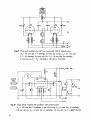
During the early intense neutron generator period (second half of the seventies) when several such machines had been constructed for fusion oriented research and neutron therapy, it became clear that these originally DC generators
would be more suitable for fusion studies if a pulsing system helped the DDX and
neutron transport measurements. The Osaka OCTAVIAN generator and the JAERI FNS
were equipped with nanosecond pulsing units as the first intense neutron generator, the RTNS-I at LLL.
There are some limitations of the recent generators in determination of the
data required for fusion reactors (low yield, small irradiated volume, large gradient of the neutron fluence in the sample). Therefore, new machines are under
38
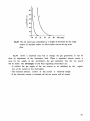
200 kV
c
._.
o _
O
*—
O
2-
1-
10
30
50
70
TARGET LOAD [ kW ]
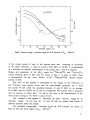
Fig.15 Specific neutron yield vs specific target load for solid
tritium targets [35]
100-•
a
10
JO
E
t/i
-2
K) -|
ScH
cr
./;
S3 K ) - |
1.8
2
10-6.
XX)
300
500
700
TEMPERATURE [ * C ]
Fig.16 The equilibrium pressure for some metal hydride systems vs temperature
construction or improvement, e.g. the conceptionally new Osaka generator and the
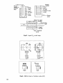
Los Alamos supersonic gas target system.
A 200 kV acceleration voltage and 50 mA current produce a load of 10 kW on
the target, which gives about 10 n/s yield if the beam is selected for D
(see
Fig.15) [34].
Since the thermal stability of the tritium targets depends on the equilibrium pressure of the metal titride system at a given temperature, the use of more
39
Table 12.
Some characteristics of intense neutron generators [32]
Name
Yield
1012[n/s]
RTNS-I
RTNS-II
LANCELOT
OCTAVIAN
LOTUS
Chalk River
Lewis/NASA
Sandia
" 6'x6' "
NRPB
DYNAGEN
FNS
AWRE
Bratislava
Kiev
INTTF
Dresden
Debrecen
Wisconsin
Lanzhou
6
30
6
4
5
4
>1
4000
10
>1
3
5
2.5
>1
>1
>10
>1
>1
>1
<1
V ace'/I target
[kV/mA]
400/22
380/130
160/200
300/35
250/500
300/25
300/30
(200/40A*)
250/250
600/10
500/12
400/20
300/12
300/10
250/15
180/200
300/20
200/20
300/5
Beam diam.
Application
[mm]
6
10
50
30
(50 cm2)
10
54
(200 cm2)
1800
6
20
15
10
10
10
16
15
10
(gas)
10
irradiation, TOP
irradiation
irradiation
irradiation, TOP
irradiation
irradiation
therapy
irradiation
radiobiology
irradiation
therapy
irradiation, TOP
—
irradiation, TOP
irradiation
target devel.
irradiation
irradiation
therapy
irradiation
Note the high current (40 A) for the Sandia generator
stable titrides than TiT has many advantages. The target cooling is a fundamental
problem for intense neutron generators, and therefore the use of a technically
perfect gas target assembly is recommended to increase the yield of present-day
neutron generators. At an equilibrium pressure of 100 Pa the corresponding temperature for the TiH, ZrH, ScH, ErH and YH systems are 390, 590, 700, 790 and
860 Celsius, respectively. The behaviour of the TiH, ScH and ErH systems is shown
in
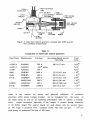
Fig. 16 [35], and a survey of these generators is given in Table 12.
Most of these neutron generators have solid
rotating targets and minimal
beam line components to achieve the highest possible neutron output. The mixed
(DT) beams were used to increase the target life at LANCELOT and LOTUS. A gas
40
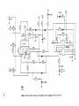
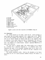
80 BEAM LINE
WORKSHOP
TARGET
TARGET ROOM I.
p
,jg
/BEAM PROFILE MONITOR
G.V.
VACUUM PUMP
QUAORUPOLE LENS
— GAS A N A L Y Z E R
n
GATE VALVE
EXPERIMENTAL PORT
o
O
*
0
-^
A ' ^
ROTATING TARGET
0" BEAM LINE ^
/|
TARGET ROOM TJ.
Q.L.
DEFLECTION MAGNET
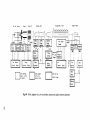
MOTORALTERNATOR
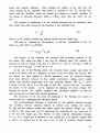
U
DEFLECTOR
G.V
ACCELERATION
\
Q.L.\
TUBE
U
\
/'
ION SOURCE
ACCELERATOR ROOM
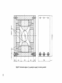
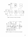
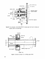
Fig.17 Top view of the FNS facility at JAERI, Tokai-mura, Japan
ANALYZING
MAGNET
ION SOURCE
• Jl
target is used only at Wisconsin University.
The target problems, the tritium
handling and the shielding require special buildings in the case of intense neutron generators. RTNS-II, OCTAVIAN and FNS were constructed in their own building
together with the supporting electronic and mechanical workshops. The relative
amount of associated equipment inside and outside the generator hall can be
estimated on the basis of the top view of the FNS facility in Tokai-mura (see
Fig. 17) [36].
42
5.0 ION SOURCES: OPERATION PRINCIPLES,
MAINTENANCE AND TROUBLESHOOTING
5.1 HIGH FREQUENCY ION SOURCES
Low voltage D-T generators employ three types of ion source: radiofrequency
[37-39], Penning [also called PIG (Philips Ion Gauge)] [26,27,40,41], and duopla-
smatron (DP) [31,42-44]. A comprehensive monograph on atom and ion sources has
been published by Valyi [44], discussing in detail both theoretical and practical
aspects. The advantage of RF sources is their high monatomic ratio ( - 9 0 %),
while PIG and DP have high currents.
The high frequency ion source proposed by Thonemann and co-workers [45] and
improved at Oak Ridge [37] is applied in different versions in many laboratories.
The high frequency discharge in HF ion sources can be generated by an inductively or a capacitively coupled oscillator of 15 to 100 MHz frequency with a
power consumption of 100 to 400 W. The discharge generated by the high frequency
electric field applied to two electrodes placed outside or inside the discharge
tube is called either capacitively coupled or linear high frequency discharge.
This type of ion source is used in the SAMES (called later AID), MULTIVOLT, etc.,
neutron generators (see Fig. 18) [37].
The discharge generated by the high frequency magnetic field in the discharge tube placed inside the solenoid of the high frequency oscillator is called
inductively coupled or ring high frequency discharge. This type of HF ion source,
used at KFKI, Toshiba, etc., neutron generators is shown in Fig. 19 [39].
In both cases the discharge chamber of about 30 to 50 mm diameter and 100
to 200 mm long is made of Pyrex or quartz glasses.
The free electrons are accelerated by the induced alternating electric field
E and will oscillate at the same frequency as the oscillator. For the condition
of ignition of the ring HF discharge it was found that the maximum value H of
the applied alternating magnetic field (H = H sintwt) must satisfy the equation
2EIrT
+
("V
rH
°
where r is the radius of the tube, (a is the angular velocity of the high frequen
cy field, and mc is the mass of the electron. The collisions between electrons
and gas particles lead to ionization only if E6 =6 eEA
a E-, where
A is the
1
C
mean free path of electrons of energy EC and E-1 is the ionization energy.
43
Cooling fin (Al)
Pyrex glass
Discharge tube
(Pyrex glass)
To oscillator
(100 MHz)
Cement
(polyvinyl acetate)
Magnet coil
Cooling
Gas inlet
Extracting electrode (Al)
Fig. 18 Capacitivefy coupled high frequency ion source [37]
The ignition voltage IL of the gas discharge depends on A and a) = 2nf. The
dependence of U, on f for different gases (at the same pressure) is shown in Fig.
20. In Fig. 21 the curves show the UL = U, (f) function for argon gas at different gas pressures. It is obvious that the minimum value of Ui and that of the
associated frequency increases with increasing pressure [44].
_2
Experiments show that the ignition voltage at pressures below 10 mbar is
independent of the nature and pressure of the gas in the discharge tube and that
its value is primarily determined by the secondary electron emission coefficient
of the discharge at the wall. In high frequency ion sources, the walls of the
discharge tubes are important because, in a real case, the secondary electrons
play a role owing to the impurities on the wall, which are usually caused by
electrode evaporation. The impurities will reduce the extracted ion current and
thus the efficiency of the ion source.
As can be seen in Fig. 18, the ions are extracted through a 1-4 mm diameter
and 5-20 mm long channel in the hard aluminium extracting electrode using a po44
-Quartz
-Extracting electrode (Al)
- Anode(W)
Quartz
Focusing lens
Fig. 19 A version of a high frequency ion source [44]
(V)
p-30jjHg
Ar
500
AGO
300
200
100
Xe
0
10
20
30
40
50 (MHz)
Fig.20 Ignition voltage vs frequency
45
(V)
1000
120jiHg
800
600
400
200
0
50
100
150
(MHz)
Fig.21 Ignition voltage vs gas pressure
Inhomogeneous
magnetic field
Homogeneous
magnetic field
0
200
400
600
800 (Oe)
Fig.22 Extracted ion beam density in HF discharges vs static magnetic field
tential difference variable from 2 to 10 kV. To decrease the power and gas consumption, a permanent magnetic field is applied to the discharge volume either
transverse or axial to the axis of the tube. By an axial magnetic field the ion
concentration at the extracting electrode can be increased because the electrons
will circulate on a helical orbit at a Larmor frequency
(9)
46
(W)
/j=1.56*10~2mmHg
200
f=30MHi
160
120
80
40
H (Oe)
0
1
2
3
4
5
6
7
8
Fig.23 Dependence of the power consumption vs magnetic field and extracted
ion density vs high frequency power [44]
and consequently the ionization probability will increase. Furthermore, the plasma with diamagnetic behaviour is compressed in the presence of a magnetic field.
The magnetic field parallel to the electric field can be either homogeneous
or inhomogeneous. It was found that the ion current density in the linear high
frequency discharge is substantially higher in the presence of an inhomogeneous
magnetic field (see Fig. 22).
The power consumption of the discharge and the luminosity of the plasma show
a resonance type increasing in a given interval of the static magnetic field
(see Fig.23). This resonance phenomenon can be observed at a pressure of
-3
2
p =1x10 to 5x10 mbar. The resonance in
high frequency ring discharges (inductively coupled HF ion sources) has been observed in transversal magnetic
fields at frequencies:
<WH = 1.5 CD to
3 (o
(10)
while in longitudinal fields at frequencies:
TJ = 3 a) to
6 ft>
(H)
47
5.2 EXTRACTION OF IONS FROM ION SOURCES
Well collimated ion beams with small diameter, which are mainly required in
neutron generators, can be obtained only from sources equipped with an ion extracting system. The probe-type and the diaphragm-type extraction systems are
generally utilized in the neutron generators. In ion sources (mostly HF ion
sources) with probe-type ion extraction and in those utilizing the expanded plasma surface, the ion-optical system is similar to an immersion lens
(objective).
04.4
08.1
I
04.4
r
012
Fig.24 Probe-type ion extraction system (quartz sleeve and extractor
electrode of SAMES neutron generators), Sizes are in mm
48
Fig.25 Schematic diagram of electrostatic immersion lens-type extraction and
the relation between the parameters
In ion sources (mostly Penning ion sources) with diaphragm-type ion extraction,
where the electrodes are shaped so as to reduce the space charge effect in the
ion beam, the extracting system is similar to
a
quasi-Pierce-type
ion-optical
system. The scheme of a probe-type extracting system is shown in Fig.24.
An immersion lens (objective) consists of two electrodes, both with diameter
D. One of them is of length h and closed at one end while the other electrode
(open at both ends) is placed at some distance from the first. The relations between the parameters of this simple immersion lens are shown in Fig.25 (graph).
It can be seen from the figure that for h<0.785D, the distance K of the image is
negative. It means we have a virtual image: for h = 0.785D, the distance K = ±m
and for h < 0.785D the image is real and the distance of the image decreases as h
increases.
In the optimum case the parameters of the extracting system are chosen so that
the total cross section of the ion extracting channel in the electrode is fully
utilized while the
ion current on the channel wall is diminished. Therefore, the
magnification h of the immersion lens defined by
K
M = ZF
(12)
should be chosen to have a value close to unity (K~2h). For other values of this
magnification the transmitted ion current decreases and for its low values the
angle of divergence of the ion beam increases on leaving the channel. Under
49
0
2
4
6
8
10
Fig.26 Diaphragm-type ion extraction and its focusing characteristics
these conditions, the h and D parameters of the probe-type extraction system are
restricted to the values in the range of
0.6D * h * 0.9D
(13)
The actual characteristics for J. ion current versus extraction voltage U .
should be determined experimentally.
The diaphragm-type extracting system is applied in Penning and duoplasmatron ion sources. This system can ensure a precise geometry with a well defined
emitter plasma surface, and it can also be used for HF ion sources.
In the Fierce-type optical systems the electrodes are shaped to prevent the
divergence due to the space charge effect in intense ion beams. This ion-optical
system is based on the principle that the direction of a charged beam between the
two surfaces of two concentric spheres with different radii is not affected by
the space charge (see Fig.26).
The relation between the extracted ion current J. and the extraction voltage
U
ext
is given by
J
i •
KU
ext
(14)
The most important parameters are the length 1 of the metal probe (aluminium) sonde and the length h of the quartz sleeve over the metal probe (see
Fig.24).
An extraction arrangement of a quasi-Fierce geometry is shown in Fig.26 with
electrodes of approximately ideal shape.
50
Magnet (BaFe)
Tin-
Extraction voltage
V
Cooling fin
'Discharge tube
(quartz)
^^
Magnet ( BaFe)
Gas inlet
\
Insulator
Insulator (Al.O, )
Extracting electrode ( A l )
Fig.27 Capacitivefy coupled HF ion source with quasi-Fierce extraction
The
quasi-Pierce-type extraction systems
consisting of two conical
electrodes are used in duoplasmatrons, Penning (PIG) and duopigatron type ion sources
with oscillating electrons.
The quasi-Pierce-type extraction system is used with HF ion sources as well,
especially in those neutron generators where the HV terminal and the accelerator
are placed in a tank under pressure of SF6 or oil. Fig.27 shows such an HF ion
source with high (5-10 mA) extracted ion current.
In an arrangement shown in Fig. 19, by applying a frequency of ~ 45 MHz at
100 W output power and UCXlT =6 kV, an ion current of 5 mA with a gas consuption of ~ 15 cm /h has been achieved [31].
5.3 MAINTENANCE OF GAS DISCHARGE PYREX BOTTLE
After several hundred hours of operation, a thin metallic layer is deposited
on the inner wall of the discharge bottle, which can lead to a reduction in the
atomic ion ratio of 40 to 50 %. Metals are good catalysts for the recombination
of atomic ions; this should be considered in construction of ion sources. The
recombination coefficient on a relative scale for most
metals is about unity,
5
-4
while for Pyrex: 2 x 10 ; quartz: 7 x 10 ; aluminium: 0.3. The surface recombination of the ions at the exit canal is decreased by applying a quartz sleeve
51
that acts as a virtual anode and focuses the positive ions into the channel in
the presence of extracting voltage. During the
operation, aluminium sputtered
from the extraction channel is deposited onto the inner surface of the quartz
sleeve, causing an increase in the fraction of molecular ion component to well
over 40 %. This means that after a long-term operation (50 to 100 h) the glass
balloon and the quartz shield surrounding the canal must be cleaned or changed.
For cleaning, a solution consisting of 80 % HF (40 %) and 20 % HNO3 (100 %)
is recommended. The layer deposited from the inner surface will disappear within
10-15 minutes if the discharge balloon is rotated around its axis horizontally in
the presence of a few mm thick layer of the solvent. After cleaning, the balloon should be washed carefully with distilled water. The same procedure is required to clean the quartz sleeve. The
metal extractor tips ( soldered into the
ion source balloons) should not be etched with the HF + HNCs solution.
The brownish deposit - carbon layer from the oil vapour - is a very adhesive layer on the surfaces of the glass, and it can be removed only by mechanical
procedure.
The aluminium extractor tip (canal) should be changed in every case. The
mechanical cleaning of its surface is simpler but the diameter of the hole must
remain.
Cleaning the dirty glass parts of the HF ion source usually results in a
shorter lifetime of the component. Use the "cleaned" balloons and quartz sleeves
only in case of emergency because, after cleaning, they will always give a lower
beam current.
Before starting a long irradiation (> 20 hours) always change the extractor
tip, quartz sleeve and Pyrex bottle.
5.4 HIGH FREQUENCY OSCILLATORS
The high frequency oscillators in the 15-100 MHz range are coupled to the
discharge balloon inductively, while at frequencies
>100 MHz they are coupled
capacitively. The high frequency oscillators are fed by a
ca. 500-1500 V, 0.5 A
anode power supply. The active component of the oscillator is an HF triode, tetrode or pentode type transmitter electron valve. The circuit diagram of a simple
but reliable oscillator of about 100 W output power is shown in Fig.28. The circuit is a three point type oscillator and it oscillates at about 27 MHz frequency. The coil L^ is the inductive coupling coil of the oscillator, surrounding the
Pyrex discharge balloon of the ion source. The 5 nF capacitor and the coil
1^2 protect the anode power supply against the high frequency. The grid and the
cathode resistors ( 7.5 kQ and 220 Q respectively ) are high power (ca. 20-30 W)
52
!KOOV m a x )
220
—CD— I—-— -- ,—-ft
———e
-ft
Fig.28 Circuit diagram of a 27 MHz - 100 W ion source oscillator
(V1 =OT100or GL8005;Lj = 50mm dia, 2x5 windings, 4mm dia CuAg;
Ly= 18 mm dia, 3 x 12 windings, 0.8 mm dia Cu; L? = 18 mm dia,
40 windings, 1.0 mm dia Cu)
wire wound resistors. The 60 pF
resonant circuit capacitor is ceramic high voltage tube type; the 1 nF and 5 nF capacitors are inductance-free disk type.
The shape of the high frequency may be observed by an oscilloscope probe
placed in the
vicinity
of the
oscillator. The bandwidth of the oscilloscope
should be at least 30 MHz.
To pick up the signal from
the oscillator, a simple wire, as aerial, or
small coil on the end of the coaxial cable input may be used. Use always the 1:10
probe at the AC input of the oscilloscope to avoid accidental damage to the vertical input. If the shape of the oscillation is not sinusoidal and shows some
saturation, this is an indication of the
abnormal operation point of the
oscillator valve: the tube or the grid resistor should be changed.
A push-pull type oscillator of
100 MHz frequency,
using two triodes, is
shown in Fig.29. The output power is about 200-250 W, and the circuit forms a
grounded-grid, symmetrical oscillator. The metal ceramic plane valves are vented
by forced air by a normal fan (like fans in the 19" cabinets) and they are placed
in two metal tubes. The feedback trimmers are air insulated disk type; the gridto-cathode resistors are 50 W wire-wound. The current consumption of this oscillator is about 200-400 mA at the maximum anode voltage. The advantage of this
oscillator is the easy and
distortion-free output power, which
can be changed
53
*"+
Fig.29 Push-pull oscillator for HF ion sourceswith 200 W output power
(Li = 40 mm dia, 5.5 windings, 3.0 mm dia CuAg; Ly = 24 mm dia,
4 x 20 windings, 0.6 mm dia Cu; L^= 20 mm dia, 40 windings,
0.7mm dia Cu; V = V= GS-90B or GU-6B or TL2/300)
-*+UQ( 1100V max.)
!0
Coupling
ring
SP
5T
5p
SFH 350
J
7~
ID
LS sg
12V
BU208
C
GND
*U F
Fig.30 Capacitively coupled HF oscillator with optical pulser
(Lj = 100 mm dia, 2 windings, 4 mm dia CuAg; Ly= 8 mm dia, 50 windings,
0.8 mm dia Cu; L^ = 8 mm dia, 11 windings, 1.0 mm dia Cu; Vj=QQE 06/40)
54
by the anode voltage. The diameter of the coil L. fits that of the ion source
balloon used. This oscillator is utilized at the KFKI neutron generator.
A capacitively coupled oscillator of about 200 MHz frequency is utilized in
the SAMES neutron generators. This push-pull oscillator is constructed on the
basis of a double tetrode. The output power is coupled to the ion source bottle
by two metal rings. The use of the double tetrode allows an easy pulsing possibility by grounding the suppressor grid through a high voltage, high frequency switching transistor, which is driven by an optical cable. For the DC mode
neutron generator, disconnect the wire between the suppressor grid to the collector of the BU 208A transistor and ground the collector of the transistor. The optical coupling between the ground and the HV terminal may be light cable or
(screened) Perspex rod. The circuit diagram of the oscillator and the pulsing
unit's receiver is shown in Fig.30. The transmitter of the light pulser may be a
commercial pulse generator-fed infrared LED.
5.4.1
Troubleshooting of high frequency oscillators
The discharge tube (ion source balloon) is made of glass, so the colour of
the HF discharge gives information on:
- the vacuum condition of the system
- the condition of the gas supply
- the power of the HF oscillator.
The HF oscillator should be tested if the discharge in the ion source bottle
is poor or totally absent but the vacuum system and the gas supply operate correctly. The operation of the oscillator can be detected by a neon lamp or a tube
light. If a small neon lamp, fixed on a 20-30 cm long Perspex (or any other isolator) rod is placed near the oscillator (close to the anode or to the coil), the
lamp should light when the HF oscillator operates (see Fig.31). A tube light (1840 W of power) already indicates the output power of the oscillator placed in the
vicinity of the HF coil
(Fig.32). The tube light will light up if the oscillator
works. The intensity of the tube light depends on the output power of the oscillator.
Neon lamp
\
Perspex rod
20-2Scm)
Fig.31 The neon lamp indicator of HF oscillation
55
Brighter light
u\U
Fig.32 The use of tube light for testing an HF oscillator
Incandescent
lamp
Ion source
Fig.33 Qualitative measurement of the output power by incandescent lamp
The incandescent lamp also gives a qualitative indication of the output power of the high frequency oscillator: for higher power the light is brighter
(Fig.33).
If the tube light or neon lamp lights up in the vicinity of the oscillator
but there is no light in the discharge tube, this indicates that vacuum is bad
(high pressure) in the whole system.
In normal operating conditions the light emitted from the balloon is vivid
reddish-violet or bright pink. A light blue colour indicates bad vacuum in the
discharge balloon or that the D~ gas is dirty, containing air.
For testing the neutron generators the use of H2 gas instead of deuterium is
recommended. The difference is only the lack of neutron production on the blind
target or constructional parts, which is an advantage when testing and repairing
56
neutron generators. (The bremsstrahlung still exsists!) If the discharge is greyish-pink or light blue and
the extraction current shows a weak plasma, it can
happen that there is no more Y>2 ^ in tne bottle or that there are problems with
the pressure regulator valve
(palladium leak, thermomechanical leak or needle
valve). If the D~ bottle has a built in manometer, check the pressure in the
bottle.
ATTENTION: All maintenance, troubleshooting and repair on the HV terminal
must be done only after first grounding the HV terminal. If the terminal is not
grounded, the 500-1000 V anode voltage can be lethal. The neon lamp and incandescent lamp may only be used with a sufficient long isolator (Perspex) rod.
When the indicators do not show HF oscillation, the HF oscillator should be
checked. Test the following components and parts:
1)
2)
3)
4)
5)
All of the electromechanical connections of the oscillator.
At power on, check:
- Filament voltage and current
- Anode voltage and current
- Suppressor voltage and current (if it exists).
At power off, check:
- Conductivity between the contacts, coils and along the condensers
- Resistance of the resistors.
The operation of vacuum valve(s) of the oscillator.
The operation of the anode power supply.
For capacitively coupled ion sources of some 100 MHz, the twin tetrode QQE
06/40 is used. Because the two anodes are connected by a thick, rectangular, silver plated copper bar which can span the two anode pins, the glass-metal soldering of the anode pin sometimes cracks, leading to the exposure of the vacuum
valve to air. If this happens, a larger white area can be observed on the glass
wall of the tube, which is caused by the chemical reaction between the getter material and the air.
In push-pull HF oscillators - used usually in inductively
coupled ion sources - the changing of the two tubes should be carried out simultaneously. A test circuit for determination of the operational characteristics of
the vacuum tubes is recommended: the lack of oscillation in the case of a pushpull oscillator may have been due to the poor characteristics ( emission) of one
or both tubes.
For the repair of HF oscillators always use the same quality components:
- Silver coated electromechanical component should not be used without a reason
(e.g. HF coil, anode-, grid- connections, capacitor holder).
57
- The wire-wound resistors should be changed to the same size and value (in ohms
and watts) components.
- The condensers used in the HF oscillators should be inductance-free (mostly
mica) and high voltage capacitors.
- The trimmer condensers are usually
air insulated. The actual size and details
related to the mechanical mounting can be copied from the original solution.
- The some 100 W power of the HF oscillator is high; therefore, for the measurements on an operating HF oscillator do not use electronic (i.e. digital) multimeters. The simple ANALOG MULTIMETERS are recommended.
5.5 PENNING ION SOURCES
The cold cathode arc discharge ion sources
with oscillating electrons in
the magnetic field are known as PIG-type sources. The operating principle of this
source is demonstrated in Fig.34. The K, and Kj plane electrodes are at the same
negative potential to the ring-shaped A anode of R radius. The
electric field
drives the electrons towards the anode. If a magnetic field B with a direction
indicated in the figure is also present, the electrons will move along expanding
helical trajectories. The maximum radius of the electron trajectory
re,max
at
orrio
given geometrical arrangement depends on the magnitudes of E and B, as well as on
the direction of the electron velocity to the magnetic field. With a sufficiently
high B value, the r CuLlLcLA < R requirement can be assured, and thus the electrons
from K, will continue to proceed towards the K-. electrode. The negative potential
of the K electrode prevents the electrons - which lost a part of their energy in
-o-
-o-
Fig.34 Operating principle of the Pennine-type ion source
58
elastic and inelastic collisions - from reaching the surface of Kj, and they will
return towards the K~ electrode. This process is repeated at the Kj and 1C, electrodes and the electrons create an intense gas plasma by further collisions. If
the energy of electrons decreases below a critical value, they can strike the anode.
The number of oscillations n of the primary electrons can be calculated from
the x mean freee path covered by the electrons in the oscillation [44]:
2d
where d is the distance between the cathode surface and the anode ring.
The value of depends on the pressure p and the probabilities of the
elastic (a-ic and elastic a)e collisions:
in-
The number of the collisions will decrease with increasing pressure in the
ion source. The mean free path x can vary for different gases. For example, for
electrons of 100 eV energy in H~ gas, x = 500 cm (n = 20); in He gas x = 800 cm
(n = 32); and in N~ gas x = 140 cm (n = 6).
In the case of the Penning source, the extracted beam contains only about 40
to 60 % of atomic ions as a maximum. In spite of the low atomic ion fraction, PIG
ion sources are often applied in neutron generators, even for deuteron energies
lower than 200 keV, because of their simple construction, cooling, power supply
system, inlet gas-flow requirement, and long operating lifetime. The Ua is usually about 5-10 kV; the I is in the range of mA. The current from the ion source
the density of the plasma - can be regulated by changing the anode voltage. The
Penning ion sources are usually equipped with permanent magnets, so they are
ideal ion sources for sealed tube neutron generators.
The extraction of the ions from the discharge in the Penning ion sources is
usually made by a diaphragm-type extraction system.
The self-maintaining discharge is influenced by the cathode material through
the secondary electron emission induced by positive ions striking the surface.
Al, Mg, and Be cathodes coated with oxides require low ignition voltage (U- = 300
to 400 V). The oxide layer can be regenerated by operating the ion source for 10
to 30 min with oxygen gas. The lifetime of oxide cathodes substantially increases
if 2 to 10 % oxygen gas is admitted to the ionized gas. Low ignition voltage (400
to 800 V) is required also in the case of Fe, U, and Ti cathodes. Metals suitable
59
Vacuum gauge
Hi
Anode
Magnets
Ferrous
cathode
Nonmagnetic
(stainless steel)
Magnetic
circuit
Annular
permanent
magnet
Pyrex
tube
Extracting
electrode
Cathodes
Anode
Base
Fig.35 Typical Penning ion source - schematic (left) and actual
scheme (right)
Rubber
seal
for use as cathode materials with high U- values are as follows [44]: Ni, Zn, Al,
Cu, C, W, Mo and Ta, for which the ignition voltage is between 3600 and 1700 V.
In most cases, Ta cathodes are applied (U- = 1700 V); however, Mg, Al, and aluminium alloys have also been used as cold cathode material because of their high
sputtering thresholds [46].
A cold cathode PIG ion source with axial extraction is shown in Fig.35. A
9
magnetic field of about 0.03 to 0.7 W/m , supplied either by a permanent magnet
or by a solenoid, is applied between the electrodes. The PIG sources are operating with gas pressures in the discharge volume of 0.1 to 2.5 Pa at gas consumption of 20 to 500 cm /h NTP. A typical PIG source can operate continuously over
200 h at about 2 mA beam current without the need for replacing the cathode or
anode.
A typical HV power supply feeding a Penning ion source is shown Fig.36.
Since the ion source requires a U ~ 10 kV potential, this high voltage is usually produced by a voltage doubling circuit.
5.5.1 Troubleshooting of Penning ion sources
The problems causing improper operation of this ion source can be divided
into three groups: magnetic, mechanical, electric.
The magnetic problems are caused by the decreased field strength of the permanent magnet so that the radius of the electron trajectory increases - resulting
in a lower discharge current I than during normal operation at the same U voltage. Similarly, every shunting of the
magnetic circuit will have
similar effects.
-CZh
Primary
from
variac
-0 +
o-
Penning
ion source
0%
Fig.36 A voltage-doubling HV power supply of a Penning ion source
61
The mechanical problems may be caused by:
- contaminated cathode surface (due to the oil vapour in the vacuum
system),
- alteration of the original anode-ring-cathode geometry,
- a change in the geometry or surface properties of the extraction slit.
The electrical problems can be caused by the:
- HV power supply: transformer, rectifiers, condensers, limiting resistor
R
L- HV connectors: on the HV supply or on the Penning ion source (the HV
feedthrough),
- HV cable between the power supply and the ion source.
Testing the magnetic circuit needs some magnetic field measuring instrument,
but the field strength in the ion source must not be tested directly. Some iron
objects (bolts, screws, etc.) accidentally bypassing the magnetic circuits can be
observed visually, while the magnetic
short circuits inside the ion source can
be found only after dismantling the source.
If the source is opened, carefully clean the ceramic HV leadthrough, the
cathode and the anode surfaces. The oil deposit on the cathode can be removed
only by sandpaper and polishing paper. After drying the surfaces, clean them
with organic solvents. When the components are dry, assemble the ion source. If
the extraction slit becomes bored out by backstreaming secondary electrons,
replace the plasma extraction cup with a new orifice insert (if it was used in the
original ion source). Test the mechanical position of the extraction electrode.
The electric test of the power supply and the ion source requires a high
voltage voltmeter (up to 30 kV) and a MQ meter, using a couple of hundred volts.
Test the HV transformer, the rectifiers and the condensers. The components
can be checked with a normal, everyday multimeter through an HV probe. The resistors Rr and Rwj can be tested similarly with the same multimeters. Test the HV
cable and the connectors under working conditions as well. The operation, the
insulation of the HVPS and the source can be tested at atmospheric pressure. If
the system seems to be working electrically normally the fault should be searched
for elsewhere, for example in the gas supply or in the vacuum system.
62
6.0 DEUTERIUM LEAKS
The ratio of atomic to molecular ions depends on the operating time of the
ion source, the pressure in the discharge volume, and the purity of the gas entering the plasma. A carefully designed pressure regulator must be applied to
guarantee the stable flow rate and the purity of the gas during long operation
time. The three most commonly used deuterium leaks in neutron generators are palladium leak, thermomechanical leak and the needle valve.
The palladium leak can be utilized for the regulation of hydrogen gas (isotopes) flow which discriminates against other gases. The thermomechanical leak
and the needle valve are suitable for the regulation of all types of gases. As
the neutron generator uses deuterium for feeding the ion sources, all of these
leaks may be found in the vicinity of the ion sources on the high voltage terminal.
6.1 THE PALLADIUM LEAK
One of the best gas regulators is the "palladium leak", constructed of palladium-silver alloy [2]. Palladium has temperature-dependent permeability to the
passage of hydrogen isotopes and discriminates against contaminant gases between
300 and 400°C. Characteristics of the I - P d system make it possible to supply the
low intensity RF and PIG ion sources with the necessary amount of hydrogen or
•5
deuterium gases at a consumption of 10 to 20 cm /h NTP. Permeation of hydrogen
through a palladium tube of 2 mm diameter, 100 mm length, and 0.1 mm wall thick•5
ness is about 5 cm /h at 400°C, which value is enhanced significantly by the use
of Pd-Ag alloy. The rate of permeation of hydrogen through palladium is higher
than that of deuterium, the ratio Pj-j/^D ranging from about 1.2 to 2.5 depending
on temperature and the condition of the Pd metal [47,48].
The usual setup of a palladium leak consists of a palladium tube closed at
one end which is heated either indirectly by a separate heater spiral or directly
by resistance heating. The palladium metal has special features: about one litre
of hydrogen gas can be absorbed by one gram of palladium. The two usual constructions of Pd leaks are shown in Fig.37.
The indirectly heated palladium leak manufactured of glass is usually connected to heavy water electrolyzers. The directly heated Pd tube is placed inside
a high pressure D~ tank.
A common disavantage of palladium leaks is ageing. After about 150-200 h operating time the transparency of the palladium will decrease at a given temperature and the leak gives a lower D2 flowrate. If this takes place the heating of
£
63
02 to the ion source
(pressure ~1(T1-1(r2mbar)
Pd tube
Thin glass insulator
Heater spiral
Up -6-10V AC/DC
Up~1-2A
Filling inlet
valve
(I
Manometer
/^~~*\ /
.
"
^
Out let
n to the ion source
p ( p~10~1-10~2mbar)
Atmospheric pressure
(Ibar)
glass cone
joint
Insulated
feed -through
02 tank
p>1bar
C
S ———
— Pd tube
Up ~ 0.5 - IV
Ip -10-12A
D2 tank
(pressures Ibar)
Fig.37 Directly and indirectly heated Pd leaks
the Pd tube should be increased. As the heating in both cases (indirect and direct) is resistive, the heating can be increased by changing the heating voltage
or by reduction of the resistance of the heater.
In the case of an indirectly heated Pd tube, the heater spiral should be
shortened (cutting off 10-20 % of length). In direct heating, the palladium tube
itself is the load of the low voltage power supply (transformer): the Pd tube resistance
can be decreased by sliding the isolated F, contact towards the lid of
the D2 tank. Shortening the original tube length by 20-50 % is a successful solution for improvement of the maximum D~ transparency of the Pd leak. At a given
potential difference the energy is dissipated in the resistor at a rate I^R0, and
so, if R = R /2, then I = 21 , i.e. the energy is doubled.
The glass-ware palladium leaks may break. If they do, lower pressure - vacuum or ion source - side should be tested by usual vacuum testing if there are
improper (gray coloured) gas discharges in the HF ion sources. The vacuum testing
of directly heated palladium leaks is carried out in a similar way. In the case
of an overpressure greater than 1 bar D~ in the tank, the sealing of the tank
should be adequate. All of the seals at the connection of the manometer, the tank
closing valve and the heater electrode should be checked regularly.
64
In the case of defective operation of the palladium leak (if the operation
of the ion source shows some problems related to the gas supply) test the
following:
- The colour of the discharge of the HF ion source: if the discharge is weak
and is slightly pink, the gas supply is not adequate - e.g., the electrolyzer
does not work properly, the filling valve is leaking and the Y>2 gas is exhausted or the heating power is not enough (contact failure).
- The palladium (tube) leaks: this can be observed if the discharge in the ion
source bottle cannot be extinguished by switching off the filament. A hole in
the thin wall palladium tube can be detected by usual vacuum leak testing
methods, and the repair requires soldering with silver at the workshop of a
precision goldsmith if there is no replacement for the defective Pd.
6.2 THE THERMOMECHANICAL LEAK AND THE NEEDLE VALVE
These two mechanical leaks have two major problems: they can fail to close
properly or they cannot be opened. Their repair requires a well equipped precision mechanical workshop and an experienced tradesman. The electrical troubleshooting of a thermomechanical leak is similar to that of a palladium leak. The
high flow rate in the case of a closed valve can be caused by stain or dirt in
the canal of the leak. The dismantling, cleaning and assembly should be carried
out with precautions. Anybody who is not familiar with the structure of these
leaks must not open them for cleaning or repair. The best solution for the repair of these elements is to send them back to the manufacturer for repair and
readjustment.
6.2.1 The thermomechanical leak valve
The operation of the thermomechanical leak is based on the differential
thermal expansion coefficients of different materials. The leak itself consists
of a metal ball held by a ceramic rod against a precision seat with an orifice.
The orifice and the ball form the valve seal. The outer cylinder, the container
wall around the ball and the ceramic rod are directly heated electrically. The
expansion of the cylinder is greater than that of the ceramic rod, so the seal
between the ball and its seat will be gradually opened.
The leak rate of the thermomechanical leak valve depends on the temperature
of the outer wall of the leak, i.e. on the electric current used for heating the
wall. In the case of a heating current switch-off or power failure, the ball will
be reseated to the seat and the valve closes. In the case of an electric power
cut-off, this valve will protect the neutron generator against exposure to
atmo65
Gas outlet
(ion source)
metal ball
ceramic rod
Direct heated
metal cylinder
Good electrical
contact
0-1 V AC
Fig.38 Schematic diagram of a thermomechanical leak valve
_ E
E
«-
a
^^
-12
-8
—r~
10
20
30
[ mV (AC)]
Fig.39 The leak rate vs heating voltage of a thermomechanical leak
spheric or D~£ pressure. The operational principle of a thermomechanical leak is
shown in Fig.38.
The thermomechanical leak is a precise component and therefore the concurrent exposure to corrosive gases and atmospheric moisture may damage the valve. A
typical leak rate (torr 1/s) or gas consumption (bar ml/h) is shown in Fig.39 as
a function of the heating voltage of the outer wall of a thermomechanical valve.
6.22 Maintenance and troubleshooting of thermomechanical leaks
The thermomechanical leak valves should be connected to the vacuum system
(ion source) in a correct way relative to the direction of the gas flow. The di66
rection of the gas flow is usually indicated on the valve. Flush the thermomechanical leak valve with dry nitrogen (or other dry gas) in the case of uncertain
operation. Check the electric contacts of the leak valve. As the heating current
of the cylinder is usually higher than
10 A, the electrical connections should
be checked and cleaned regularly. As accurate AC current measurement in the range
of several tens of amperes is not simple (it can be done by a digital clampmeter
for AC heating current), calibrate the heating voltage along the cylinder while
it is working properly. The voltmeter contacts should be separately connected to
the cylinder: in case of a bad contact between the filament transformer and the
leak body, this voltmeter will indicate the condition of the contacts. Opening
the welded body may kill the whole leak valve.
In case of lack of heating test the following:
- The primary side of the stepdown transformer (voltage and current)
- The secondary voltage across the leak valve (it should be the nominal value)
- The voltage drop across the secondary coil and thermomechanical leak
contacts. There should be a small (~ 1-10 mV) voltage drop along a good
contact.
If the contacts are defective, clean them and test again.
If there is a grayish-pink discharge in the RF ion source, check the vacuum
and deuterium connections. If these connections are in good condition, there may
be some cracks along the body of the leak.
6.2.3 Needle valves
Needle valves are used for controlled admittance of fine gas flows into
the ion sources. They can be operated either manually or electromechanically. Reliable and popular needle valves for ion sources are the BALZERS EVN 010 HI and
EDWARDS FCV 10K types. The variable leak needle valve of VARIAN includes a movable piston with an optically flat sapphire which forms a variable seal completely free from friction, seizing and shear. All these valves can be used for very
fine gas streams for adjustment of the gas pressure in the ion sources. The fine
adjustment of the stream is performed by adjustment of the position of the needle
or the sapphire piston. The movement of the needle is controlled through a
threaded shaft or a threaded shaft-and-lever mechanism having a mechanical advantage of up to 10,000 to 1 [49].
For a BALZERS EVN 010 HI valve an exchangeable, easy-to-clean dust filter is
fitted into the lateral small flange port by which the valve can be connected to
the gas bottle of the ion source. The main parts of the valve are made of stainless steel or rustproof material, and the valve seat is made of lead. In a closed
position the valve needle is forced into the preformed conical seat by a spring
67
17-
1
HOUSING
11 GUARD RING
2
3
4
5
6
7
8
KNOB
SCALE DRUM
SOCKET
NEEDLE
FILTER
NUT
SPRING
12
13
14
15
16
17
9
COVER
LOCKING WASHER
NEOPRENE O-RING
VITON O-RING
SEAL
SCREW
COVER
18 THREADED PIN
19 THREADED PIN
10 BALL BEARING
Fig.40 A typical needle valve
SCALE
TURNSCStO n
101- 100 i • • •
=b.
— (~r-
E VN OK H2-
103 10
10Z
EVN010H1?< - -s
iff
f^
1
X*
101 0.1
mO
/
1(T3
/-
•*^
^,'
^
^•£;=•
—
10~2
10"
10
GAS FLOW ( m b - l / s ) FOR AIR
10°
Fig.41 Gas flow rate curves for BALZERS needle valves [49]
(Sk = scale marks of the micrometer-like scale drum
n- number of turns of flow rate adjusting knob)
68
which ensures a constant closing pressure. Over-tightening the valve during closing may damage the needle and/or the valve seat. Moving axially in one direction
the needle is coupled to the actuating knob over a ball bearing. The fine thread
of the knob ensures that the needle is lifted reproducibly from the seat. The
scale ring and actuating knob are coupled to each other for easy adjustment. This
allows a simple setting of the opening point at any time and marking a specific
gas flow as 0-point for accurate reproducibility. Usually, the adjustment of this
valve tends from a maximum conductance of ca. 130 mbar 1/s to a minimum of
_Q
1x10" mbar 1/s NTP (i.e. the leak rate in closed position). The construction of
the needle valve is shown in Fig. 40 [49]. The gas flow rate - the air admittance - of the EVN 010 HI (and EVN 010 0 H2) is shown in Fig.41.
The conductance of a needle valve depends on the viscosity of the gas to be
admitted into a vacuum chamber. If gas other than air is used, the original calibration curve can be utilized only by taking into account the viscosity of the
given gas related to air. Table 13 shows the viscosity of the most frequently
used gases [49].
Table 13.
Viscosity of the most frequently used gases
Gas
r\ Viscosity [Poise]
Air
Nitrogen
Carbon monoxide
Oxygen
Carbon dioxide
Hydrogen
Water vapor
Helium
Argon
Crypton
Xenon
K = r\ air / rj gas
1
1.04
1.05
0.9
1.24
2.07
1.97
0.93
0.82
0.73
0.8
180
173
172
200
145
87
93
194
220
246
225
For a laminar gas flow in the needle valve, the following equation
used for correction of the flow rate Q of the admitted gas:
V
=
*air/ ^gas
x Q
air = K
x
^air
Imbar '/*]
can be
W
69
Example 1:
For a neutron generator, where the ion source should be fed by deuterium gas
), the preset conductance of 10" mbar 1/s for air (Sk scale mark of
needle valve EVN 010 HI is about 13, based on Fig. 41) will be higher than for
air owing to the K value of hydrogen (2.07).
As Fig.41 shows the gas flow is higher than 0.001 mbar 1/s, a flowrate below
this
value can be set reliably
calculated on the basis of
if a vacuum gauge is used.
The gas
flow
Q = Ap x S [mbar 1/s]
can then be
(18)
where the gas flowrate is Q [mbar 1/s]. the pressure change in the vacuum chamber
is Ap [ mbar ] and the pumping speed of the vacuum pump is S [ 1/s ].
Example 2:
If the pressure in the vacuum system is increased from a value of 2x10"
3x10" mbar and the pumping speed is 100 1/s, the value of Q will be:
Q = 10"6 x 100 = 10"4 [mbar 1/s]
to
(19)
Gas flows below 10" mbar 1/s can be set relatively easily by means of a
vacuum gauge. Experience has shown that a lower limit of ca. 10" mbar 1/s
can be reached, but that the long term stability of the valve begins to decline
at gas flowrates below 10" mbar 1/s.
6.2.4 Maintenance of needle valves
Needle valves do not require any maintenance, in general. In the course
of time, however, some contamination effects will become apparent. Very fine dust
particles
can
still pass through
the filter of the
inlet port of the needle
valve and they can settle in the gap between the needle and the needle seating.
Adjustment of the low gas flows becomes difficult and the leak rate of the
closed valve deteriorates. These symptoms indicate that the valve requires cleaning.
The dismantling and cleaning procedure of needle valves is
BALZERS EVN 010 HI type valve in the manufacturer's Manual [49].
70
described for
a) Dismantling the valve (see Fig.40)
-
Take off the cap (9) from the actuating knob (2)
Remove locking washer (12) from spindle needle (5)
Unscrew knob (2) with scale drum (3) counterclockwise from sleeve-socket (4)
Remove screws (16) and sleeve-socket (4)
Pull out carefully spindle (5) together with spring (8) and K (shape) ring
(14) from valve body (1)
- Undo the screw (7) and remove filter (6).
b) Cleaning the dismantled valve parts
Wash needle (5) seating, filter (6) and the hole in the valve body (1) with
chloroethane or similar, using a soft brush. Carefully remove any deposits from
the needle using a soft tool of wood or plastic. Then rub the needle vigorously
but carefully with a cloth drenched in solvent cleaner. Make sure the needle surface is clean and smooth.
IMPORTANT NOTE: DO NOT BEND THE NEEDLE DURING THE CLEANING !
Rinse all parts in alcohol or acetone (in an ultrasonic bath if possible)
and dry them. Blow out the seating with clean compressed air or hair dryer. Be
sure that the seating surface is score-free and smooth. Wipe the holes and sealing surfaces of sleeve (4) and valve body (1) with lint-free cloth drenched in
alcohol, remove all dirt and dust. Finally rinse O-ring (15) and K-ring in alcohol or acetone (if possible in an ultrasonic bath).
c) Reassembling the valve
Slightly grease O-ring (14) and K-ring (15) with Flombin
grease
(or
silicon
grease) and slide them onto spindle (5).
Be sure to protect the needle from contact with lubricant !
Carefully insert spindle needle (5) with washer under the
valve body (1) until needle rests in the seating
spring into
- Slide spring (8) onto spindle (5)
- Fasten sleeve (4) to valve body (1) using screw (16)
Screw actuating knob (2) with scale drum (3) clockwise onto sleeve
groove of spindle (5) protrudes clearly over ball bearing (10)
- Attach locking washer (12)
- Close the actuating knob (2) with cap (9).
(4)
the
until
71
d)
-
Adjusting the spindle clearance
Take off the cover-cap (9) from the actuating knob (2)
Remove locking washer (12), guard ring (11) and ball bearing (10)
Adjust clearance with threaded pin (21)
Assemble in reverse sequence.
e) Testing the needle valve after cleaning
Open and close the valve about 10 times to compensate for any rough spots.
The leak-tight valves should fulfill two requirements:
- Leak tightness of the valve seat in closed position (needle/seating)
- Leak tightness between valve interior and valve surrounding.
Tightness of the second type is less important because such leaks merely result in gas losses to the atmosphere if the needle valve is used to regulate the
gas consumption of ion sources from gas tanks of more than 1 bar pressure.
If the valve operates correctly it must be possible to alter the gas flow
smoothly, without steps. If the direction of the rotation is changed the valve
must react immediately. The values of the calibration curves for
mbar 1/s should be reproducible within about 10%.
0.01 or
0.1
f) Leak testing the valve with vacuum gauge
The leak-tightness of a valve can be checked with the vacuum gauge which is
normally installed in any vacuum system.
- Valve seat: Evacuate the closed needle valve to a low pressure and close the
gas inlet flange with a blanking plate. Open the valve slowly about five turns to
evacuate also the valve interior. Close the valve and wait until the pressure
stabilizes. Remove the blanking plate abruptly and observe the meter. If there is
a leak at the valve seat there will be a pressure rise in the vacuum chamber
which will be indicated by the meter.
- Valve interior: The valve interior is sealed by a K-shaped ring, the K-ring.
Again, the gas inlet flange must be closed by a blanking plate and the valve
opened. If the valve interior is leak-tight, the same pressure must be reached
irrespective of whether the valve is open or closed. As mentioned above, a
leaking valve interior only means a certain loss of the gas admitted.
Compared with
the results
obtainable
with sensitive leak detectors, this
testing method yields a relatively low detection limit. For qualitative testing
this is normally sufficient because leaks, which would be detrimental to the vacuum system, can be detected easily by a vacuum gauge. Leaking valve seats can
only be repaired by the manufacturers. Leaks in the valve interior are mainly
caused by contaminated or damaged seals.
72
g) Testing leaks with halogen or helium detector
- Valve seat: Connect the closed valve to the leak detector and admit test gas
into the gas inlet port via a fine (dust) filter.
- Valve interior: Cover the gas inlet port with a blanking plate and slowly open
the valve about five turns. This also evacuates the valve interior. Now, blow the
outside of the valve with test gas.
If the valve is in good condition, the leak-tightness values must reach the
technical data. Similar halogen or helium leak testing procedures can be used in
thermomechanical valves.
6.3 CALIBRATION OF LEAK VALVES:
GAS CONSUMPTION MEASUREMENTS OF ION SOURCES
In the case of abnormal operation of
leak valves, their transmission
should be tested. The gas consumption of the ion sources is usually measured in a
practical unit of ml/h NTP ( Normal Temperature and Pressure ), i.e. 20°C and
1 bar; the gas consumption unit is ml bar/hour, which can be converted into the
usual flow rate, pumping speed unit of 1 mbar/s . The gas consumption of the HF
or Penning ion sources at the neutron generators is in the range of 1 to 10 ml/h
NTP, while the duoplasmatrons and other high current ion sources consume 10 to
100 ml/h NTP gas. This means, the leaks should assure the gas flow into the ion
sources in the range of 1 to 100 ml/hour NTP gas. The U shaped manometer - which
is the usual equipment for determination of the pumping speed of the vacuum
pumps - can be used for the measurement of the gas consumption and the characteristics of the gas adjusting valves. For the determination of the
gas consumption
Vacuum
system
Rubber
gas balloon
(H2.D2)
Fig.42 Setup for the measurement of flow rate of ion source leaks
73
v
—1*>—'
r^~^
^^J shaped
glass tube
mounted
vertically
|
E-
mm
scale
1-
Silicon oil ~
rr.
-=
L.
j =j
Fig.43 The U shaped glass tube manometer used to determine the pumping speed
and gas consumption of ion sources through the measurement of the
flow rate
of the ion sources, a good gas adjusting valve, the U shaped manometer and an extra gas container (usually plastic balloon) is needed (Fig.42).
The setup with the U shaped glass tube filled with silicon oil for the calibration of gas leaks and pumping speed measurements is shown in Fig.43.
The valve connecting the upper part of the U shaped manometer serves to
equalize the pressure in the two separate vertical legs of the manometer.
6.3.1
Measurement
Regulate the gas leak for the required value of the gas flow. This can be
detected, for example, by the optimal colour gas discharge in the HF ion source.
The valve connecting the two legs of the U tube is open. The flow rate (gas consumption of the ion source) can be measured in such a way that the volume of the
gas entering from the plastic balloon into the gas leak valve (into the ion
source) in a given time will be determined.
Close the valve which bypasses the legs of the U tube manometer and start a
stop watch. The gas entering into the leak valve will flow from the left leg of
the U tube, causing a pressure drop against the right leg of the U tube. The level of the silicon oil will rise at the left hand side and decrease at the right
hand side. While waiting for an easily observable volume of gas consumption (say
1-3 ml) stop the stop watch. If the fall of the silicon oil level took a time At,
the flow rate through the gas leak (the gas consumption of the ion source) will
be
X =
74
4At
(20)
where d is the inner diameter of the U shaped glass tube. If the diameter d and
the Ah oil level change is measured in cm and the At time in hours, the flow rate
and the gas consumption of the ion source will be given in ml/h NTP. This unit is
suitable for other purposes as well: based on the consumption, the normal operation time of an ion source (neutron generator) can be calculated from the ^2 8^
container volume.
The gas flow rate value may also be calculated for other pressures. In the
case of a needle valve the adjustable flow rate is usually given at lower pressures, e.g. in mbars. This measurement makes it possible to check the characteristics of leak valves given in manufacturers' data sheets and their recalibration after repair.
The U shaped tube filled to half height with silicon oil is also a useful
tool for determination of the pumping speed of vacuum pumps. Pumping speed measurements will be found in Section 9, which describes the vacuum systems and vacuum components of neutron generators.
75
7. DEUTERIUM ELECTROLYZERS
Deuterium gas needed for the operation of neutron generators is commercially
available, but many laboratories produce their own D~ gas to supply their accelerators. The deuterium consumption of a RF or Penning ion source is below 10
ml/h NTP, while a duoplasmatron needs about 20-100 ml/h. These gas consumptions
can be satisfied by a simple laboratory electrolyzer. The Toshiba and the KFKI
neutron generators even have their own electrolyzers with palladium leak on the
HV terminal to supply the HF ion source.
The Toshiba neutron generator uses a heavy water electrolyzer of a few ml
heavy water with a built-in palladium leak. The construction of this Pd leak with
heavy water electrolyzer is shown in Fig.44 [50] .
The production rate of the electrolyzer can be adjusted by setting the conductivity, the pH value, of the heavy water electrolyte. The solution is usually
alkaline: by putting a couple of KOD or KOH tablets into the heavy water. If the
electrolyzer produces more deuterium gas than the consumption of the ion source,
the water level will sink in the central glass tube and the cathode contact will
be cut off.
This electrolyzer works normally if the conductivity of the electrolyte is
set up properly, i.e. in the 0.2 Q" cm" range. A part of the tip of the cathode electrode is immersed in the electrolyte, which can sometimes cause a KOH deposit formation on the
cathode surface. This insulating layer can prevent the
to leak
Joint
Anode +
~ Cathode
Mercury
_^ cut
Electrolyzer
Fig.44 Heavy water electrofyzer of the TOSHIBA NT-200 neutron generator
76
a ®
a ON
0
6
a OFF
*
Si
02
03
LED bar
Sx1.2K
D 2 0 ELECTROLYZER
AND Pd LEAK
INFRA LIGHT
TRANSMITTER
Fig.45 Optical fiber isolated Pd leak control and electrofyzer for the
deuterium supply of ion sources on the HV terminal
flow of the electric current from the electrolyte, especially if the neutron generator has been out of action for a long time.
This disadvantage of the simple electrolyzers was eliminated by KFKI [51] in
their U shaped electrolyzer-Pd leak system, by using two cathodes. The upper
cathode (electrode No.2 in Fig.45) switches on a relay which remains switched on
through the lower cathode of the electrolyzer (electrode No.3 in Fig.45) until
the electrolyte level sinks under the level of the tip of the lower cathode. As
77
the electrolyte level rises again up to the upper cathode - due to the gas consumption of the ion source - the relay switches on and the electrolyte level
sinks again due to the operating condition. Using this hysteresis principle of
the KFKI electrolyzer, a heavy water electrolyzer-Pd leak system with optical fiber connection for the regulation of the deuterium flow into the ion sources has
been constructed. This system can be used for the gas supply of the HF, Penning
and duoplasmatron ion sources. The circuit diagram of the system is also shown
in Fig.45 [52].
The electrolyzer works on the hysteresis principle described above. The
heater of the Pd tube is controlled by a switching (Darlington) power transistor.
The on-off ratio of the transistor is controlled through a LED phototransistor
optical link by an astable
multivibrator at
the ground
potential. The optical
connection can be a simple 3 mm diameter Perspex rod or plastic (insulating) fiber cable which endures the high voltage differences between the electrolyzer (on
the HV terminal) and the LED driving pulse generator (at the ground potential of
the control desk). The effective heating current of the Pd leak is controlled by
the duty-cycle of the astable multivibrator pulse generator. The heating current
of the Pd leak is displayed on the electrolyzer by a simple linear 5 LED bar indicator. Similarly, the D2 level status of the
"hysteresis"
switching
relay is
shown by a green and a red LED.
The electrolyzer-Pd leak systems are very economical solutions for the deuterium supply of a neutron generator.
The deuterium supply of commercial neutron generators can be solved also by
separate heavy water electrolyzers at the site of the neutron generator laboratories. An electrolyzer for filling the ion source deuterium vessels can be
constructed on the basis of Fig.46. This electrolyzer can produce 100-500 ml/h NTP
deuterium gas with a simple (sometimes not water cooled) electrode stucture and
can serve as the deuterium supplier for the neutron generator and other utilizers. The whole glass system of the electrolyzer can be manufactured by a
skilled glass-blower or made of commercial laboratory glassware.
Before starting the heavy water electrolysis, the electrolyzer and the deuterium vessel should be evacuated. A simple mechanical pump is used after opening the
valves V|, X^, and V-,. The mercury level in the long (800 mm) vertical glass tube
indicates when the whole system is evacuated. Closing the valve V^,, the mercury
level, as in a manometer, shows the tightness of the system. The mercury level
should not sink if the vacuum-tight system is properly sealed. If the Hg level
does not sink within about 10 minutes, the heavy water electrolyzer can be put
into operation. To get clean deuterium gas, heavy water and deuterized alkalis
(DO + NaOD, KOD, LiOD) as electrolyte can be used. Since the amount of hydrogen
78
Liquid nitrogen
trap
Mercury
traps
vessel
for
ion
sources
(ca. 11)
Water cooled
jacket
Pt electrodes
Fig.46 Electrolyzer for filling deuterium tanks of neutron generator ion sources
in the solution of 1-2 g NaOH or KOH is negligible compared to the 100-200 ml
D-O, the utilization of normal alkalis to set the conductivity is not usually a
problem. Depending on the thickness of the Pt tube electrodes and the Pt wires,
the power supply is a 20-50 V/2-3 A unit. A full wave rectifier with variable
output voltage is suitable. The output voltage is usually regulated by a variac
or triac on the primary side of the step down transformer.
79
The electrolysis should start with low current. The voltage
(and the current) of the electrolysis should be increased gradually. To prevent the conical
taps from falling out, the deuterium vessel should not be filled up to the atmospheric pressure. When the electrolysis stops, the Vj and ¥2 glass taps should be
closed, and the O-ring sealed connection between the electolyzer and the
deuterium vessel can be vented into the atmosphere by the valve V^. With two
identical deuterium vessels, the deuterium supply of the accelerator will
be smooth and uninterrupted by the use of the electrolyzer.
7.1 THE FLOAT REGULATOR ELECTROLYZER
The regulation and stabilization of the deuterium pressure in the ion source
need some control circuits related to the different gas valves. The combination
of an electrolyzer with a mechanical float regulator can serve as a reliable gas
Fig.47 Construction of the float regulator-electrolyzer [53]
(numbers are explained in the text)
80
supply for the ion source. The regulating electrolyzer, described below, has been
used satisfactorily for a long time at Bratislava [53].
The construction of the regulating electrolyzer is shown in Fig.47. The main
component is a float (4) filling almost the whole volume of the cylindrical chamber (1). The electrolyzer is closed from the upper side of the flange (2) in the
center where there is a nozzle (3). The float has small points (5) round its circumference that prevent the float jacket from directly touching the inner surface
of the chamber and at the same time allows the float to move freely along the
axis of the chamber. In the center of the upper lid of the float there is an
elastic rubber seal (6). On the inner and outer walls of the lower edge of the
float are the platinum electrodes (7) of the electrolyzer. The chamber and the
float are placed in a glass vessel (8) partly filled with the electrolyte D2O
with the addition of KOD. The material of the float, the nozzle and the float
chamber is Perspex (Plexiglas).
In order to understand the operation of the regulating electrolyzer, let us
assume that the whole free space of the float chamber is filled with the electrolyte, so the float is pushed upwards till it closes the inlet of the nozzle by
its elastic seal. If DC voltage of appropriate polarity
is applied to the
electrodes, the electric current starts to flow between them, and deuterium gas production starts at the inner negative electrode. The deuterium gas gradually fills
the space between the float and the inner surface of the float chamber, pushing
the electrolyte out. With a gradual decrease
of the electrolyte
level in the
float chamber, the force P, by which the float presses the seal to the nozzle,
will also decrease. The force P can be described by
P
=
^D2sh - G + -* d2 (p2 - PI)
(21)
where
D = diameter of the float
s = specific density of the electrolyte
h = height of the electrolyte level measured from the bottom of the float
G = weight of the float
d = diameter of the inlet of the nozzle
P2 = deuterium gas pressure above the electrolyte
p, = deuterium pressure at the inlet of the nozzle
81
The size and mass of the float as well as the diameter of the nozzle inlet
should be chosen so that the following relations for each term of eq. (21) are
fulfilled:
D2sH > G and G »
d2 ( P ' P >
(22)
where H is the height of the float.
If the construction of the regulating electrolyzer obeys these conditions,
the force P at a certain electrolyte level h = h decreases so much that a leakage appears between the rubber seal and the nozzle edge and deuterium flows from
the float chamber into the vacuum system of the ion source. The leakage grows
with further decrease of the
electrolyte
level until the
gas quantity
q that
flows through the leakage into the ion source equals the quantity Q originated by
the electrolysis, i.e. until
q =Q
(23)
becomes valid. If the electric current in the electrolyzer circuit is changed,
the quantity of the gas achieved by electrolysis is changed as well. By the corresponding change of the electrolyte level in the float chamber the leakage between the rubber seal and the edge of the nozzle is also automatically changed
(as well as the quantity of q)
in such
a degree that a new equilibrium is
achieved, i.e. a state
at which the eq.(23) is valid. When the electric current
is switched off, the electrolyte level gradually rises up to the level
at which
the nozzle actually gets completely closed. The time behaviour of the equilibrium
settling after the change of Q is given by the equation:
dh/dt = 4 [Q - q(h)]/w (D2 - D2)
(24)
where the meaning of D and DQ is evident from Fig.47, and q(h) is the function of
the escaping deuterium quantity from the float chamber into the ion source during
unit time of the electrolyte level h. The behaviour of this function is characteristic for each construction of a regulating electrolyzer, since it depends on
the geometry and the mechanical properties of the nozzle and the seal as well as
on the geometry of the float.
The experimental function q(h) for a given geometry and construction of a
regulating electrolyzer is shown in Fig.48. The rough surface rubber float shows
a faster rising function while the fine surface silicon rubber float gives a relatively easy way to change the gas admittance characteristic of the regulatingelectrolyzer [53].
82
18
22
26
38
40 h[mm]
Fig.48 The ion source gas consumption q vs height of electrolyte for the rough
surface (1) and fine surface (2) silicon rubber seal on the top of the
float
Fig.48 shows a relatively easy way to change the gas generation. It can be
done by adjustment of the electrolyte level. When a regulated current source is
used for the supply of the electrolyzer, the gas admission into the ion source
will be stable. The advantages of this float regulating electrolyzer are:
- It enables the gas supply of the ion sources to be stabilized by the regulation of the current in the electrolyzer.
- The insulated distance control of the current is relatively simple.
- If the electrode current is switched off the ion source will be closed.
83
8. REMOTE CONTROL OF THE HIGH VOLTAGE TERMINAL
The ion source, the ion source power supplies, beam handling facilities,
etc., placed on the HV terminal of a neutron generator require normal control
during operation. Regulation of the ion source and the related devices needs a
control through the acceleration high voltage. The terminal control of a neutron
generator can be carried out by:
- mechanical control using insulators (manual drive by Perspex rod or nylon
fiber),
- electromechanical control (motor gear driven insulating rod or nylon fiber),
- insulation transformer control of the power supplies on the HV terminal,
- optical insulation in the control line of the HV terminal units,
- computer (microprocessor) control of the terminal units with serial
optical links between the ground and the HV terminal.
8.1 MECHANICAL CONTROL
This is the simplest solution for the distance control of mechanical leaks
and variacs at the HV terminal. Insulating (Perspex, Bakelite) rods are fastened
to the shaft of the needle leak or variac and there is a suitable knob to turn
the insulating rod at the ground potential. Since the insulating rod - especially
in high humidity - may conduct, the ground side of the rod should be grounded
between the the manually touched knob and the HV terminal to avoid an electric
shock to the operator. If the mechanical transmission is made of nylon fibers,
similar precautions should be taken to avoid an electric shock. A schematic representation of this simple distance is shown in Fig.49 .
HV
TERMINAL
GROUNDED
TURNING
i-KNOB
Fig.49 Insulating rod control of the regulation elements at the HV terminal
84
8.2 ELECTROMECHANICAL CONTROL
The electromechanical control of the units at the HV terminal is similar to
the mechanical control. However, instead of manual control, the rods (or fibers)
are driven electrically by servo motors, DC motors with gear, etc. The insulation
between the HV terminal and the ground is the same. Since the servo motors and
especially the DC motors with gear may produce a higher momentum, the mechanical
overload of the insulating rod, fiber or variac, and needle valve should be
avoided This is why position limiting switches are used for the electromechanically driven variacs, potentiometers, needle valves, etc. These switches
protect
the system against mechanical overdrive and, in the case of the lower or upper
mechanical limit,
allows the opposite direction
drive only. The
limit switches
are usually microswitches with NO (Normal Open) and NC (Normal Closed) contacts.
The principle of such a mechanical overload protection is shown in Fig.50.
INSULATING ROD
VARIAC
ETC.
NO
HV
TERMINAL
NO
o DOWN
MOTOR
o NO
LIMIT SWITCHES
Fig.50 Principle of mechanical protection of the electromechanical drives
This mechanical protection utilizes a twin DC power supply for the DC motor
gear driving insulating rods or fibers. The motor can be switched to the forward or backward direction by the UP/DOWN switch. This switch is a key with normal open
position. For forward motion the motor will be powered by positive
voltage, and for backward direction it will be connected to the negative voltage.
The two limit switches break the positive or negative supply when the position of
the rod (fiber) reaches the upper or lower limit. These switches ensure the return
of the gear in the opposite direction after the positive or negative supply
has been switched off.
This type of electromechanical remote control ( from the control desk ) is
utilized at the Toshiba, KFKI and MULTIVOLT neutron generators.
85
TERMINAL
POTENTIAL
+ 150 hV
n n n n
TO THE
VARIACS ON THE CONTROL DESK
n
n
INSULATING
TRANSFORMERS
Fig.51 Insulating transformer control of HV terminal
(SAMES J-15 and J-25 neutron generators)
8.3 INSULATION TRANSFORMER CONTROL
This type of ion source control is a solution for the control of a Penning
ion source or an extraction voltage. For RF or duoplasmatron ion sources the insulation transformer control is less reliable due to the high number of insulation transformers connected to the HV terminal. The KAMAN (TMC) A-111, A-1254 and
A-711 and the SAMES type D neutron generators utilize this method for insulation
remote control of the equipment at the HV terminal. In the case of a Penning ion
source this is a simple method while the RF type requires a number of separate
insulating transformers: as many as five or six, as at the SAMES J-15 and J-25
neutron generators. The probability of sparking along the surface or between the
primary and secondary sides in a single transformer is much lower than in the
five or six insulating transformers. The utilization of a single, high power insulating transformer is typical for neutron generators and small accelerators.
Figure 51 shows a block diagram of the insulation transformer remote control of
the SAMES J-25 [54].
The only advantage of insulating transformers is the easy variac control at
the ground potential.
86
660
1k
100n=*=
=: \\o
i--- U?
100n
HV TERMINAL
Fig.52 Optoisolated triac control of mains transformers to the power control at HV terminal
oo
OOV AC
The disadvantage of this type of remote control, in addition to the high
probability of electrical breakdown along the
surface of the
transformers, is
that repair of the insulated secondary coils is impossible in practice.
8.4 OPTICAL INSULATION CONTROL
The control of HV terminal equipment by optical fiber insulation can be
ANALOG or DIGITAL. Analog control is mostly used for neutron generators. However, some sophisticated neutron generators (RTNS-II, OCTAVIAN, etc.) use microcomputer control.
Analog control of equipment at the acceleration high voltage (HV terminal)
requires power supplies and other units where the regulating input needs DC voltages. This input is the usual remote input of the medium frequency power supplies and other electronically controlled devices. In a simple power supply using
one mains transformer, the variac type input voltage regulation can be changed to
a DC voltage input controlled triac control circuit. This circuit is the usual
power electronic circuit: the required DC input control voltage can be produced
after the optical insulation by simple circuits.
A typical triac control circuit with optical input is shown in Fig.52, based
on the AID (SAMES) T type neutron generator [55]. This circuit has a pulse generator unit at the ground potential which drives the infrared light-emitting diode.
This light source transmits the light pulses to the optical
receiver photo transistor by an electrically insulating optical fiber cable. The optoreceiver is on
the HV terminal. The
output pulses of the optoreceiver are integrated and the
integrator output drives the DC input of the triac (or thyristor) controller
chip. The pulse generator works at constant repetition rate ( constant pulse frequency ). The duty cycle of the pulses will be transformed into voltage at the
integrator. Figure 52 shows this
universal triac controller circuit utilized by
SAMES. The transmitter can be a TL494 pulse width modulation circuit or a NE555
timer circuit in astable multivibrator mode [56].
From a practical point of view, it is very important to use transient suppressors at the small transformer, giving a phase control signal, and parallel to
the triac. The operational amplifiers may be any of the usual types. The thyristor controller circuit may be one of the commercial type 1C proposed by the semiconductor manufacturers. The optical fiber can be substituted by Perspex rods;
the optotransmitter and receiver are recommended
to be a matched pair (like optical gate).
8.5 COMPUTER CONTROL
Increasing application of microcomputer techniques has promoted the development of a control system for processes related to accelerators. An up-to-date
88
LJ
cr
o
1/1
<
J
Umg
A.C.
POWER
J Ug
POWER
UQ
ON
OFF
\
\
I
350 kV
Uex Uf U.
UJ
ex.
MEASURING
CONTROL AND
x
STEP
MOTOR J
/
y /f
lEOj^a
yr
^
£
_rf^
*
POWER
'\
MEASURING
V
f
J
1
ON
OFF
1
AUX.
J
VACUUM
|
300 kV
(V^__p— FIBER OPTIC CONNECTION
1 [~ -tCON-MEAUTROL R ING
MAIN
\
BEAM
AUD TEC
\C
Ij-i
i
/L™/
VACUUM
——
CONTR.
r AIkj A r
Fig.53 Block diagram of the ion source control by CAMAC at the neutron
generator using intelligent CAMAC crate controller [51]
i.
i
M
graphic computer
terminal
r
>.
•
oj
•
£
ofc
"c«>
CO
-->
X 0
D
zl 3 I
^
*
o
w
^ >~^
u. _
>*
-s-
«i
0 U)(7) ^'D
^
fc
<
54
A
^
i
\/
electronics for
matching and
transfer
^x^
^
/ V'micrcx:omputer
for
communication
0
NEUTRON GENERATOR
Fig.54 Hardware system block diagram of a neutron generator control
89
+12 V
Fig.55 Optical transmitter of analog signals from control console to HV terminal
computer control system for such purposes represents an on-line closed loop system consisting of one central computer and additional microcomputers for special
tasks. Such a system reduces operating expenses and is necessary for testing and
operation of the automation of the accelerators. The microprocessor system for
neutron generators requires solution of problems related to the operation and
construction of a (cascade) generator. The open loop systems can be utilized at
the manual control of the generator, while the closed loop systems can handle the
entire control of the neutron generator operation.
The modules of the accelerator (neutron generator) control are almost standard: CAMAC or, more recently PC cards. A block diagram of a neutron generator
(with duoplasmatron ion source) control is shown in Fig. 53 [57]. In this neutron
generator the ion source is floating on the HV terminal at the potential of the
acceleration voltage + extraction voltage. The optical fiber cables allow
excellent insulation between the HV terminal and the subterminal of the ion source.
The sensors and controllers are at different potentials, in the HV area and the
ion source area, so they are connected by different fiber cables. The intelligent
CAMAC controller at the ground potential controls the ion source power supplies
and the gas supply. The measured parameters - e.g. arc current, arc voltage,
pressure in the ion source - are transmitted back to the ground potential. The
software of the system has been designed to meet requirements like starting the
generator operation, controlling the operational parameters of the generator, as
well as operator-aided control and safety control in breakdown situations.
90
+12V
TL072
3
-*-
12V
Fig.56 Optical receiver of analog signals at HV terminal with a switch-on option
+ 12V
-12V
Fig.57 Optical transmission circuit of signals from HV terminal to ground
(HVterminal to control desk)
A similar system using CAMAC data way is shown in Fig.54 [58]. The lower
part of this diagram shows the microcomputer configuration (Z-80 based). The measured ion source parameters and the output control values are using the CAMAC
data way in digital form. The analog values measured at the HV potential are connected to a multiplexer between the ADC to obtain more input. The analog output
of the DAC is also demultiplexed.
The transmission techniques and the electronic equipment in the vicinity of
the neutron generator were designed and developed taking into consideration the
noise immunity and protection from corona discharges and sparking along the system. The analog and digital (binary)
signals are
transmitted
and received by
91
+ 12V
- _ BC182
Fig.58 Optical receiver of the signals from the HV terminal
(analog meter driving frequency to voltage converter in the control desk)
glass fiber optics. The electronic components used in the terminal blocks are
radiation hardened.
The optical transmission system utilized for the transmission of the measured and control voltages is shown in Figs 55 and 56. Fig.55 shows the transmitter-receiver
configuration related to the
operator console
(ground potential)
while Figs 57 and 58 show the HV terminal-to-ground optical insulation circuits.
The circuit in Fig.55 is a voltage-to-frequency converter with infrared LED
output. This circuit is utilized both on the ground potential and at the HV terminal. The optical receiver,
frequency-to-voltage
converter
is shown in
Fig.56.
This circuit also has a comparator actuating a limit switch. This limit switch is
utilized as a mains switch-on device at the HV terminal. The analog output of the
LM 331 integrated circuit utilized in frequency-to-voltage mode is led to the remote control input of the power supplies on the terminal [59].
92
9. VACUUM SYSTEMS OF NEUTRON GENERATORS
9.1 IMPORTANT TERMS AND UNITS IN VACUUM TECHNOLOGY [60]
9.1.1 Terms
The terms used in descriptions and technical data for the pumps and components in catalogues are standardized. The more important terms given below have
been chosen to assist those less experienced in vacuum technology in the use of
the catalogues and to extend their utilization.
An absolute pressure gauge is a pressure gauge used to determine the pressure from the normal force exerted on a surface divided by its area. An absolute pressure gauge is independent of the gas type used.
Absorption is a type of sorption in which the gas
(absorbed) diffuses
into
the bulk of the solid or liquid (absorbent).
Adsorption is a type of sorption in which the gas (adsorbed) is retained at
the surface of the solid or liquid (adsorbent).
Backing pressure is the pressure at the outlet of a pump which discharges to
a pressure below atmospheric only.
Compression ratio is the ratio between the outlet pressure and the inlet
pressure of a pump for specific gas.
Concentration of molecules is the number of molecules contained in an adequately chosen volume divided by that volume.
Intrinsic conductance is conductance in the special case where the orifice
or duct connects two vessels in which Maxwellian
velocity distribution prevails.
In the case of molecular flow, intrinsic conductance is the product of the conductance of the inlet port of the conductance of the duct section and the transmission probability of the molecules. In
this flow
range, it is independent
of
the pressure.
Degassing is a desorption which is accelerated by physical processes.
Desorption is the liberation of gases absorbed by a sorbent material. The
liberation can be spontaneous or can be accelerated by physical processes.
Gas diffusion is the movement of a gas in another medium due to its concentration gradient. The medium may be gaseous, liquid or solid.
Flow:
Viscous flow is the passage of a gas through a duct under conditions such
that the mean free path is very small in comparison with the smallest internal
dimension of a cross section of the duct. The flow is therefore dependent on the
viscosity of the gas and may be laminar or turbulent. In the case of viscous
flow, the resistance is a function of the pressure.
93
Turbulent flow (eddy flow) is a viscous flow with mixing motion above a
critical Reynolds number (For circular cylindrical pipes, Re = 2300).
Laminar flow (parallel flow) is a viscous flow without mixing motion at
small Reynolds numbers.
Molecular flow is the passage of a gas through a duct under conditions such
that the mean free path is very large in comparison with the largest internal dimensions of a cross section of the duct. In the case of molecular flow, the resistance is independent of the pressure.
Gas is matter in a state of aggregation in which the mean distances between
the molecules are large in comparison with their dimensions, and the mutual
arrangement of the individual molecules is constantly changing. Gas in the
stricter sense is matter in gaseous state which cannot be brought to a liquid or
solid state by compression at the prevailing temperature.
Gas ballast is the inlet of a controlled quantity of a gas, usually into the
compression chamber of a positive displacement pump, so as to prevent condensation within the pump.
Gettering means bonding of gas, preferably by chemical reactions. Getters
(getter materials) often have large real surfaces.
Leaks in a vacuum system are holes or voids in the walls or at joints,
caused by faulty material or machining or wrong handling of the seals.
Leak rate is the throughput of a gas through a leak. It is a function of the
type of gas, pressure difference and temperature. The unit for the leak rate is:
1 Pa m3 s'1 = 1W = 10 mbar 1 s'1.
Maximum tolerable water vapour inlet pressure, pWO, is the
highest inlet
pressure at which a vacuum pump can continuously pump pure water vapour under
ambient conditions of 20°C and 1013 mbar.
The mean free path is the average distance which a molecule travels between
two successive collisions with other molecules.
Outgassing is a spontaneous desorption.
Partial pressure is the pressure due to a specified gas or vapour component
of a gaseous and/or vapour mixture.
Permeation is the passage of gas through a solid
barrier or a liquid of
finite thickness. Permeation involves diffusion and surface phenomena.
The pressure of a gas on a boundary surface is the normal component of the
force exerted by the gas on an area of a real surface divided by that area.
The legal pressure units are: Pascal as the SI unit (abbreviation Pa) and
bar as a special unit designation for 105 Pa.
1 Pa = 1 N rn2
1 bar = 1000 mbar = 105 N m"2 = 105 Pa
The unit commonly used in vacuum technology is the millibar.
94
Quantity of gas (pv value) is the product of the pressure and volume of a
specified quantity of gas at the prevailing temperature. If the pv value is to be
used as a measure for the quantity of substance or gas, this must be an ideal gas
whose temperature must be specified.
The resistance is the reciprocal of the conductance.
The Reynolds number is the nondimensional quantity
Re = ^
(25)
where
p = Density of fluid
v = Average flow velocity
1 = Characteristic length (e.g. pipe diameter)
n = Dynamic viscosity
Re < 2300 : Laminar flow
Re > 4000 : Turbulent flow
The saturation vapour pressure is the pressure exerted by a vapour which is
in thermodynamic equilibrium with one of its condensed phases at the prevailing
temperature.
Sorption is the taking up of gas (sorbate) by a solid or a liquid (sorbent).
Sorbents are also called sorption agents.
The standard reference condition is the condition of a solid, liquid or
gaseous substance determined by the standard temperature and standard pressure.
The abbreviation is NTP : Normal Temperature and Pressure.
Standard temperature:
Tfl = 273.15 K
aR = 0°C
Standard pressure:
pn = 101325 Pa = 1013.25 mbar
The throughput is the quantity of gas (in pressure-volume units) passing
through a cross section in a given interval of time at the prevailing temperature, divided by that time.
The throughput of a pump is the throughput of gas pumped.
The total pressure is the sum of all partial pressures present. This term is
used in contexts where the shorter term "pressure" might not clearly distinguish
between the individual partial pressures and their sum.
The ultimate pressure is the value which the pressure in a standardized test
dome approaches asymptotically, with normal operation of the vacuum pump and
without gas inlet. Distinction can be made between the ultimate pressure which
is due to noncondensable gases, and the ultimate pressure which is due to gases
and vapours (ultimate total pressure).
Vacuum is the state of a gas with the concentration of molecules being less
than that of the atmosphere at the earth's surface. Vacuum is the state of a gas
95
Table 14. Vacuum ranges
Low vacuum (GV)
Medium vacuum (FV)
High vacuum (HV)
Ultra high vacuum (UHV)
mbar
Molecule concentration
1000
1-10"3
3
7
10 - *y10"'
< KT
2.5xl025 - 2.5xl022m-3
2.5xl022 - 2.5xl019rn3
2.5xl019 - 2.5xl015mf3
1C
*5
< 2.5xl013m'J
The molecule concentrations refer to a temperature of 20°C.
with a pressure below atmospheric pressure, i.e. the air pressure prevailing at
the respective location. The vacuum ranges are given in Table 14. The relationship between pressure p and concentration of molecules n (for ideal gases) is:
P - n KT
K = 1.3807 x 10"23J K1 (Boltzmann constant)
T = Thermodynamic temperature
Vapour is a substance in gas phase which is either in thermodynamic equilibrium with its liquid or solid phase (saturated vapour), or can be brought to
thermal equilibrium by compression (condensed) at the prevailing temperature (unsaturated vapour).
Note: In vacuum technology, the word "gas" has been loosely applied to both the
noncondensable gas and the vapour, if a distinction is not required.
The vapour pressure is the partial pressure of a vapour.
The volume flow rate is the volume of gas passing through the duct cross
section in a given interval of time at a specified temperature and pressure, divided by that time.
The volume flow rate S is the average volume flow from a standardized test
dome through the cross section of the pump's intake port. Units for the volume
flow rate are m s" , 1 s" , m h" .
The water vapour capacity C«y is the maximum mass of water per unit of time
which a vacuum pump can continuously take in and discharge in the form water vapour under ambient conditions of 20°C and 1013 mbar. It is given in g h"1. The
relationship between water vapour capacity D^Q and maximum tolerable water vapour
inlet pressure PW is :
CWo
= 217
in g j-
(26)
S = Volume flow rate, in m3 h-1, at inlet pressure
pw
= Maximum tolerable water vapour inlet pressure, in mbar
T = Thermodynamic temperature of the water vapour pumped, in K
96
Table ISA, Multiples and units
Power of
10
Prefix
Designation
IO9
IO6
IO3
giga
mega
kilo
deci
centi
milli
micro
nano
pico
G
M
k
d
c
m
io-21
ioio-3
10"6
io-9
io-12
/"
n
P
Table 15B. Vacuum technological quantities [62]
Quantity
Symbol
SI units
Pressure
Total pressure
Partial pressure of gas
constant "i"
Saturation vapour pressure
Vapour pressure
Residual total pressure
Residual gas pressure
Residual vapour pressure
Ultimate pressure
Mean free path
Collision rate
Collision rate related
to area
Particle density
Throughput
Leak rate
Pumping speed
Conductance
Impedance
Conductance
P
N/m2,Pa
Pt
p.
PS
Pd
pr
P
Pm
"end
r, A
z
z"
n
V
s
c
R
L
m
1/s
1/s m2
1/m3
N m/s
N m/s
m3/s
m3/s
s/m3
1/s
Recommended
units
bar, mbar
mbar
mbar (e.g. pR ,pN )
2 2
mbar
mbar
mbar
mbar
mbar
mbar
m, cm
s"1
s" m" , s" cm"
m-3, cm-3
mbar 1/s
mbar 1/s
1/s, m3/h
m /s, 1/s
s/m , s/1
1/s
97
Table 16. Conversion tables
(a) Temperature
K
Kelvin
°Celsius
°Fahrenheit
OF
°C
5/9 (°F+459. 67)
5/9 (°F-32)
1
1
K-273.15
9/5 K-459.67
°C+273.15
1
9/5 ° C + 32
Pa
mbar
bar
torr
atm
1
100
105
133.32
101325
98066.5
9806.65
47.88
6894.8
0.01
1
1000
1.33
1013
981
98.1
0.47
68.95
10'5
10'3
1
7.5xlO'3
0.75
750.06
1
760
735.6
0.097
0.36
51.71
-
(b) Pressure
1
1
1
1
1
N/m2 = 1 Pascal
mbar
bar
torr = 1mm mercury
atm
2
1 at = 1 kp/cm
1 m of water
1 lb/ft2 = 1 psf
1 lb/in2 = 1 psi
at = kp/cm
1
1
1
1
1
1
1
1
1
98
N/m2 = 1 Pascal
mbar
bar
torr = 1mm mercury
atm
at = 1 kp/cm2
m of water
lb/ft2 = 1 psf
lb/in2 = 1 psi
1.82
1.033
1
0.1
mW s
0.0102
10.19
10.33
10
1
1.013
0.981
0.098
psf
-
2.09
2089
2.78
2116.2
2048.2
204.82
1
144
0.98
1
0.97
0.1
0.068
psi
0.014
14.50
0.019
14.69
14.22
1.42
1
Table 16 (Cont.)
(c) Volume flow rate, Conductance
m3/s
1 m3/s
1 1/s
1 m /h
1 ft3/min
1
10"3
2.78xl04
4.72xlO"4
1/s
m3/h
1000
3600
3.6
1
1.69
1
0.278
0.47
(d) pV throughput, Leak rate
W
mbar 1/s torr 1/s
31 Pa m3/s = lW 1
1 mbar 1/s
0.1
1 torr 1/ls
0.133
1 cm3/m (NTP) 1.69xlO"3
10
1
1.33
0.017
7.5
0.75
1
0.013
fl3/min
2118.88
2.119
0.59
1
cm3/m (NTP)
592
59.2
78.9
1
(e) Ion source gas consumption (pV throughput) unit
1 ml atm/hour = 2.8x10" mbar 1/s at Normal Temperature and Pressure (NTP)
9.1.2 Units [61]
The basic units were established in October 1954 at the First General Conference for Mass and Weight in Paris. This uniform system was given the internationally binding initials "SI" (from the French, Systeme International d'unites).
The recommended units are mostly multiples of fractions of the SI units (Table
15A). As exceptions to this, some units which have become customary in certain
branches are recommended (see Table 15B). For convenience, a conversion table is
given in Table 16.
99
9.2 VACUUM PUMPS
When selecting the most appropriate vacuum system for a neutron generator
the following important factors should to be taken into account:
(a)
The value of the ultimate pressure to be attained for normal operation:
The aim of all vacuum systems for a neutron generator, as for a charged particle accelerator, is that the accelerated deuteron ions should reach the tritium
target without collision. To do this, it is necessary to keep the pressure in the
accelerating tube so low that the mean free path of air molecules should exceed
the length of the accelerating tube.
Data at different pressures - as can be seen in Table 17 - show that the
above requirements for the mean free path values for neutron generators at pressures of 10" -10" mbar are in the range of some meters. These ultimate pressure
values, in Table 17, have to be taken into account, at least when selecting the
most appropriate type of vacuum pump [63].
Table 17. Mean free path vs pressure
Pressure (mbar)
atmospheric
1
10"3
10"6
10"9
Mean free path (cm)
6x10"
5xlO"3
5x10°
5xl02
5xl06
(b) Gas intake (due to lakage, the ion source, etc.) to be accounted for during
the run of the accelerator:
The pumping speed is an important consideration. Its required value should be
determined, first, by the regularly occurring gas intakes. Note that the pressure
in the system must not be changed during operation: for example, at a neutron
yield of 10 n/s in the case of a commercial neutron generator with a beam current of 1-2 mA, the Y>2 8as intake is 4-5 cm /h.
100
(c) Economic considerations:
-
The greatest possible simplicity in handling the
-
system (start, stop);
The lowest possible probability of failures (the pumps may break down,
-
pumps and the entire
vacuum
espe-
ally during long irradiations);
The least possible reconstruction requirements during maintenance (to repair
any parts of the system might be difficult owing to tritium contamination);
The best possible accommodation for the existing laboratory conditions
(various
supplies,
e.g. for
electric
power,
water
and
liquid
nitrogen;
replacement possibilities of failed parts of instruments, workshop
for maintenance and renewal, etc.).
made by well known manufacturers.
Fig.59 shows the
background
best known pump
types,
Taking into account both the pumping rates and cost during
operation, the
manufacturers of neutron generators use in practice one of the following pump
combinations to obtain the
10" - 10" mbar ultimate pressure (necessary for a
neutron generator):
- oil diffusion pump - rotary pump
- turbomolecular pump - rotary pump
- Ti-ion getter pumps (+ rotary pump).
The working principles of these pumps, vacuum gauges and other vacuum technical equipment, as well as the most important details of the operation of vacuum
systems containing the above fittings, are discussed below.
Ultra high
vacuum
Medium
vacuum
High vacuum
Low
vacuum
-Vi 5COU s flow -
Mol ecular flow
M«.l
h
^
.Diaphragm
Roti irv i/one
Multi - staqe dry
Rot jry plunqer
\—
Roots
Turt 0 ITolec ular
Diffusion
-Sublimation
i— Sputter ion
t—
Cryoaenic
h-
h-
A dsor ptio i
-H
H
H
Fig.59 The operation pressure range of different vacuum pumps
101
Gas ballast
inlet valve
Inlet
Exhaust
valve
Gas ballast
inlet
Pump
fluid
Sliding
vanes
Fig.60 The rotary vane vacuum pump
9.2.1 Vacuum system based on a combination of oil diffusion and rotary pumps
(a) The rotary vane pump
This is probably the most widely used pump and is well established as a
backing pump in many compound systems.
An eccentrically placed slotted rotor turns in a cylindrical stator (Fig.60)
driven by a directly coupled electric motor. In the slots are two (or three)
sliding vanes which are in continuous contact with the walls of the stator. Air
drawn in is compressed and expelled through a spring loaded exhaust valve.
The vanes and rotor are sealed by a fluid film and the stator is immersed
in the fluid to provide heat transfer to the pump casing. Rotary pump fluids are
usually selected from high quality mineral oil with low vapour pressure and good
lubricating properties. Suggested types of oil are:
Shell Rotary Vacuum Pump Oil
Gluvacol R 910
Alcatel 1DO
ELF MOVIXA PV100
TURBELF SA 100
ELFLL BARELF F 100
BP CS 100
INLAND 15
INVOIL 2D
SHELL VITREA 100
TOTAL CORTIS 100
Two-stage rotary pumps are frequently used, in which the exhaust from thefirst stage is internally connected to the inlet of the second stage (Fig.61).
102
Inlet
Exhaust
Fig.61 Cross section of a two-stage rotary vane pump
Fig.62 The operation of the gas ballast in a rotary vane pump
Gas
molecules
Inlet flange
•HH
w.
— Vapour jet
Cooling.
coils
Condensed .__«•
vapour
o*
Hot
vapour -
o
B
Exhaust flange
(Backing line)
y[ | iQL®—fi «i .
»
1—*
i
9
c
3
.** o-*- »
in
iii>rlij~iiTlr~-^ r>..._
im^lJ^TTTT-^p^p
Ejector jet
flujd
Heater
Fig.63 Schematic cross section of a diffusion pump
103
This solution improves the
ultimate
pressure of the
pump by
reducing the back
leakage where the rotor and stator are fluid sealed.
To reduce the condensation of vapours during the compression cycle, gas
ballasting can be used, where a controlled quantity of a suitable noncondensable
gas (usually air) is admitted during compression (Fig.62).
In Fig.62, vane A is about to close the crescent-shaped chamber B containing
the gases and condensable vapours being pumped. As this volume is sealed from the
inlet, a controlled volume of air at atmospheric pressure is admitted at point C.
The air intake raises the pressure in B and prevents condensation of vapour by
opening the exhaust valve before the conditions of condensation are reached.
(b) The diffusion pump
The operation of the diffusion pump can be seen in Fig.63. The pump fluid
(usually oils with large molecules) is heated
electrically
and the
oil vapour
streams through the chimneys. Then the vapour molecules - emerging from the
(ring-shaped) nozzles with supersonic speed - are directed toward the cooled pump
wall, where condensation takes place. The vapour condensate reflows to the bottom
of the boiler. This process can be maintained continuously by permanent heating.
Air molecules in the pump - and in the connected vessel - can be mixed by
Brownian movement (diffusion) between the oil molecules while moving towards the
wall; thus, in all probability, air molecules can get - by collisions - a velocity component directed downwards because their mass number is much smaller than
that of the oil molecules. Gases compressed in this way in the lower part of the
pump can be removed by the backing pump.
The condition of the operation is that the mean free path of the oil molecules
should be greater than the distance from the nozzle to the wall. This condition
can be reached in such a way that - before switching on the diffusion pump - the
whole vacuum system should be evecuated to a forevacuum (10-1-10-2 mbar) by applying a forepump (usually rotary type) as backing pump to the diffusion pump. In
addition, the rotary pump must be kept in operation as long as the diffusion pump
works in order to prevent the disintegration of the lowest vapour jet stream system because of the accumulation of gases from the diffusion pump at the exhaust
passage towards the backing. On disintegration, the velocity of the air molecules
in the upward direction is the same as that in the downward direction. This is
interesting because a jet's disintegration leads to a gradual breaking down of
the pumping ability.
The value of the necessary forevacuum at the exhaust passage of a diffusion
pump is at least 10-1 -10-2 mbar. However, the pumping speeds of the rotary pumps
in this pressure range are usually quite low (see later). It is usual to insert a
so-called booster-pump in between the two pumps if the gas intake is high.
104
In older vacuum systems, an overheated diffusion pump, only at the pressures
10 - 10 2 mbar, was used as a booster. In this way, the exhaust pressure of the
booster increased into the mbar region, where the rotary pumps also have high
enough pumping speeds.
In contemporary diffusion pumps the booster stages are originally built in
the housing (stator). Fig. 63 shows that the outstreaming of the oil vapour
from the pipe directed towards the exhaust passage - operates as an oil vapour ejector pump.
1
Table 18. Technical data for diffusion pump fluids [64]
Mineral oils
BALZERS
61
71
Theoretical vapour
pressure [mbar]
2
Viscosity [mm /s]
(at 25°C)
Chemical resistance
Thermal resistance
Pressure range
Price
Silicon oils
Pentaphenylaether
DC704
AN 175
SANTO VAC 5
2xlO"7
2xlO"8
2xlO"8
4X10'10
IxlO'10
171
410
39
175
1000
good
good
good
good
better
better
better
better
best
10-2-5xlO'6
low
^
very good
7
10"3- 10"7 10-10"' 10"5-10"8 10'3-10~8
low
medium medium high
Suggested types of diffusion pump fluids are as follows (Table 18):
Mineral oils
These oils are manufactured by molecular distillation of
crude oil and they
are suitable for general applications down to a pressure of 10" mbar. They will
not withstand repeated exposure to atmosphere in a hot state because the exposure
will produce carbonaceous compounds with high vapour pressures which decrease the
performance of the pump. Their deposits on the inner surface of the accelerator
system will produce conducting layers.
105
Silicon oils
These oils are exceptionally stable compounds at high temperatures and they
will provide an ultimate pressure between 10-5 to 10-9 mbar. Their deposits on
the electrodes of an accelerator will produce an insulating layer. These fluids
are poor lubricants.
Pentaphenylaether
These fluids have exceptionally low vapour pressure and are thermally very
stable. They will not backstream in a properly designed pump and baffle, and they
are chemically stable. Their break-up on the surfaces
of the electrodes of an
accelerator will produce a conducting layer. They are good lubricants, but they
are expensive.
—Vacuum chamber
^|
High vacuum
Isolation -
lonization gauge
Roughing valve
Fore-line
trap
Diffusion
pump
valve
Rotary pump
Fig.64 Typical diffusion pump vacuum system
(c) Combination of diffusion and rotary pump
A typical system consisting of an oil diffusion pump and a rotary pump can
be seen in Fig.64.
As mentioned earlier, selection of the appropriate diffusion pump is determined, first of all, by the gas consumption of the ion source. On the other hand,
for the selection of the rotary pump - to be fitted to the diffusion pump - the
pumping speed of the diffusion pump as well as the maximum permissible pressure
at the exhaust have to be taken into account.
106
For example, in the case of a diffusion pump having 1000 1/s pumping speed:
—4
if a pressure as low as 10 mbar is assumed for the pumped volume (in fact, it
should be higher than that), then a 3.6 m /h pumping speed is necessary at the
exhaust side with a 10" mbar pressure. Such a pumping speed can be achieved even
by the simplest rotary pumps with a pumping speed of 6-8 m /h in practice (see
the pumping speed diagrams).
Cooled vapour traps: The
so-called foreline traps - liquid nitrogen traps between the rotary and diffusion pump protect the diffusion pump from the oil
vapour of the rotary pump. This must be impeded in order to prevent mixing the
rotary pump oil with the much finer
diffusion pump oil. This is necessary because such mixing would spoil the diffusion oil (the molecular size being much
larger for diffusion than for rotary pump oils).
A vapour trap has another very important role: it prevents the vapours (especially steam), generally present in vacuum systems, from getting into the rotary pump. A rotary pump cannot completely remove such water (or even steam). Practical experience shows that the use of a trap improves the vacuum by at least
half an order of magnitude.
The FREON-12 cooled traps are advantageous in laboratories where liquid nitrogen supply is either difficult
or impossible to obtain. The manufacturers of
diffusion pumps usually stock this type of refrigerator operating cooled traps as
well.
Fig.65 shows some simple forms of cooled vapour traps. It is quite practical to put a vacuum trap in the inlet chamber of the diffusion pump; this reduces
the risk of getting diffusion oil into the
accelerator tube and helps to limit
the different vapours present in the vacuum system. Further questions on the
correct use of a vapour trap are discussed later.
Buffer chamber: Sometimes it is worth while to insert a buffer chamber with a
volume of 3 to 5 litres - usually made of stainless steel - between the oil
diffusion and the rotary pumps ( see Fig.64 ). In the case of power cut-off, the
buffer chamber will play an important role and take over the duty of the rotary
pumps for a short time (until the diffusion pump cools down). Owing to its relatively large volume, it can pump out, for a while, air from the exhaust port of
the diffusion pump that is still working and reduce the contact of its oxygen
with the still hot oil vapours.
Isolation valves: Diffusion oils in contact with air may absorb a lot of humidity from the air and gaseous material, which will be released again when the
pump is started up and results in extra gas intake. Therefore, after stopping the
vacuum system of the generator, it is worth while to isolate the diffusion pump
107
——»
(Vacuum
chamber or
diffusion
pump
—
—
-——
^ ^_
_ ——»•
=
^
—
L^^J^~
Vacuum
— —.
Rotary
pump
__ _-—. _^.
- ——
_- Liquid
Nitrogen
^Liquid
Nitrogen
.^Stainless steel
vessel
—— _
—-Glass
vessel
1
^:—- Rotary
numo
\ Inlet for liquid
rnr
11
— — '"-— — —
.
D*
Nitrogen
^Accelerc
tube
——7— — —~^IE~^3 — Liquid
Nitrogen
\
\
Inner cylindrical
vessel
Fig.65 Liquid N~ cooled traps
Fig.66 Different types of isolation valves [65]
108
from the other parts of the vacuum system by valves (see Fig.66). These valves
are usually quarter swing or butterfly valves. The acceleration tube and the target beam line are usually isolated by gate valves. In this way, air is admitted
only into the small space just at the inlet of the rotary pump by the air admittance valve, while the other parts of the system keep the vacuum.
After switching off the vacuum system, the backing valve prevents the vapours
of the warming-up trap from streaming back towards the diffusion pump. The role
of this valve is similar to that of the high vacuum isolation valve.
For the safe running of the vacuum system, it is worth while to control the
cooling water supply of the diffusion pump continuously by a pressure switch;
this switches off the pump heating automatically if the water supply cuts off.
A relay indicating the pressure level - built into the electronic unit of
the vacuum gauge (vacuum gauge controller) - can also be used for a similar purpose; this relay stops (or inhibits switching on) the
heating
of the diffusion
pump if the gas intake exceeds the upper limit set in the controller.
If a neutron generator - with its vacuum system - is operated for a long
time, it is advisable to control continuously the temperature of the diffusion
pump by a thermocouple or thermal switch.
Pirani
gauge
lonization
gauge
Vent <3>
valve
Target —
assembly
Backing
valve (1)
Vent
valve (1)
Rotary
pump
Rotary
pump
Fig.67 General vacuum system for a neutron generator
109
During operation of the vacuum system of a neutron generator consisting of a
rotary as well as diffusion pumps (see. Fig.67), the following important instructions should be followed:
A. Switching on the vacuum system
a) Switch on, first, the rotary pump (backing valve 3 is opened and the vent
b)
c)
d)
e)
valve 1 is closed automatically). Let the rotary pump run for 5-10 minutes with gas ballast valve open. During this time the pump house warms
up to operation temperature (the vapours do not condense later), and, in
addition, it will be possible to release the gases and condensed vapours
from the foreline trap.
After this "cleaning", the foreline trap has to be
filled by liquid
nitrogen.
Open the backing valve 2.
Open the isolation valve 1.
Switch on the heating of the diffusion pump when the correct forevacuum
value - in the whole system - is reached.
After another period of 10-15 minutes has elapsed - this depends on the
heating-up time of the diffusion pump - the cold trap (on the top of
the diffusion pump) has to be filled up with liquid nitrogen.
B. Switching off the vacuum system
a) Close the isolation valve 1.
b) Empty the cold trap (by warming or compressed air). During this operation, the greater part of the adsorbed gases and vapours will be released, and the diffusion pump that is still working will transport
them
to the foreline trap (within about 10-20 minutes - depending on the size
of the traps).
c) Switch off the heater of the diffusion pump; let it cool down below
operation temperature.
d) Close the backing valve 2.
e) Switch off the rotary pump (now, the valves 3 and 1 will automatically be
turned off and on, respectively).
This vacuum system - as can be seen in Fig. 67 - involves the possibility
of the tritium target exchange and the exchange of the old ion-source components
- using a second rotary pump - without switching off the diffusion pump. In such
a case, the
required part of the vacuum system
- after
closing the
isolation
valve 1 can be exposed to the atmosphere. After the necessary changes have
been made, the upper part of the vacuum manifold can be evacuated by the second
110
rotary pump in order to reach the required forevacuum value and, finally, it can
be connected
- by opening the isolation valve 1 or the isolation valve 2 to
the high vacuum manifold.
9.2.2
Vacuum system based on Ti-ion getter pump
The sputter ion pump is a getter ion pump in which ionized gas is accelerated towards a getter surface, continuously
renewed by cathodic sputtering. The
basic sputter ion pump consists of two flat titanium cathodes, a cylindrical anode and an axial magnetic field as shown in Fig.68.
A typical Ti getter pump consists of two flat rectangular titanium cathodes
with a stainless steel anode between them consisting of a large number of open
ended boxes (see Fig.69).
The pump, mounted inside a narrow stainless steel box and attached to the
vacuum system, is surrounded by permanent magnets. The anode is operated at a potential of some kV whereas the cathodes are at ground potential. The cold discharge is initiated by stray electrons produced by cold field emission. These electrons execute a helical motion around the magnetic field lines and they oscillate to and fro in the axial direction between the cathodes, as in the case of
PIG ion sources or Penning vacuum gauges. The positive gas ions formed by ionization bombard the titanium cathode, sputtering titanium to form getter films on
the anode and the opposite cathode. The titanium reacts with all active gases,
forming stable compounds, and a considerable number of bombarding gas molecules
will be buried in the cathode.
Noble gases (He, Ar, Ne) are pumped by burial under the layers of titanium
on the pump walls and anode, while the other gases are buried in the cathode.
Unfortunately as further sputtering takes place, the previously buried molecules
can be released, giving rise to
instability in pumping. Various solutions to the
pumping of noble gases have been attempted, for example the use of differential
cathode materials, where one is titanium and one is tantalum, and the use of
slotted cathodes where the bombarding ion arrives at a glancing angle. However,
the most successful has been the triode ion pump configuration (Fig.70), in which
the whole pump body (B) is grounded and, being at the same potential as the anode
cylinder (A), acts as an auxiliary anode. The ions, produced as in the diode
pump, now graze the titanium lattice (C) giving a high sputtering rate, the sputtered titanium forming preferentially on the pump body.
Energetic neutral particles created by ions glancing off the cathode are bur-
ied on the surface of the pump body or are reflected and pumped at the anode. Any
positive ions arriving at the pump body are repelled by its positive potential
and do not touch the surface. Buried or implanted noble gases covered with fresh
111
c
D
Fig.68 Schematic diagram of a single cell sputter ion pump
Fig.69 Operation of the diode type sputter ion pump
• Titanium atom
O Gas molecule
B
©Positive ion
0 Electron
® Neutral particle
Fig.70 The triode-type ion getter pump
112
titanium are left generally undisturbed, leading to a higher net pumping speed
for these gases.
Before the titanium ion getter pumps start, it is necessary to reach the fore
vacuum in the vacuum system of the accelerating tube by a rotary pump. A cooled
trap between the rotary pump and the sputter ion pump adsorbs the vapours and
the humidity of the air.
As soon as the rotary pump reaches the ultimate vacuum, the ion getter pump
should be switched on for a short time. The starting current of the Ti getter
pump at the forevacuum pressure is usually high, which leads easily to overheating of the ion pumps. The switch on and off procedure should be repeated several times as the loading current of the getter pump reaches the normal working current range. During this time, the isolation valve between the rotary pump
and the getter pump should be closed, and the rotary pump should be switched off,
exposing to the atmosphere its inlet through an air admission valve. The normal
work of the ion getter pump
- in a leak-free vacuum system will be indicated by a decreasing getter pump current.
9.2.3
Vacuum system based on turbomolecular pump
The principle of the molecular pump is based on the fact that the gas particles to be pumped receive, through the impact with the rapidly moving surfaces
of a rotor, an impulse in a required flow direction. The surface of the rotor,
usually disc shaped, forms with the stationary surface of a stator, intervening
spaces in which the gas is transported to the backing port. In the original Gaede
molecular pump and its modifications, the intervening spaces were very narrow,
which led to construction difficulties.
wttr
STATOft OCCS
ftOTCftOKC
EXHAUST
Fig.71 Schematic diagram of the turbomolecular pump
113
Using a turbine form of blading of the rotor, the so-called "turbomolecular
pump" was developed as a technically viable pump.
A typical double flow pump can be seen in Fig.71. The rotor revolving at a
very high speed carries the air - by molecular impacts - towards the backing
pressure channel. In the case of lower vacuum needs
- e.g. for neutron generators mainly rotary pumps are utilized as backing pumps. The turbomolecular
pumps have the advantage over oil diffusion as well as ion getter pumps in many
respects: they can be put into operation quickly (in only a few minutes); the
vacuum system is much less polluted by oil vapours; an unexpected exposure of the
vacuum to the atmosphere does not damage the pump.
Important instructions on the use of turbomolecular pumps are as follows:
a) It is worth while to insert a cooled trap between the turbomolecular
pump and the rotary pump; this improves the ultimate vacuum and protects
the turbomolecular pump and the recipient from the oil vapours of the
rotary pump.
b) Before starting up the turbomolecular pump, it is important to check the
operation
of
water
cooling. In most vacuum systems, water cooling
starts automatically and the operation of the turbomolecular pump is interlocked by a pressure switch on the drain leg of the water cooling
pipes. If the water cooling is not automatically switched on by the forevacuum pump, wait until the pressure in the vacuum system has reached the
forevacuum level. The interlock circuit of the forevacuum controller will
inhibit the manual switch-on of the turbomolecular pump.
c) The
use of an
isolation valve
(quarter swing or butterfly valve) is
advisable between the inlet of the turbomolecular pump and the vacuum
manifold of the neutron generator. This butterfly valve is common in
most neutron generators. The operation of the isolation valves is manual,
electromagnetic or pneumatic. For smooth operation of the neutron generator, the vacuum in the manifold (and in the acceleration tube, beam line,
etc.) should be kept, but the housing of the turbomolecular pump has to
be vented to atmosphere to avoid oil infiltration
from bearing lubricating oils. The use of dry nitrogen is advisable.
d) After switch-off, the rotor of the turbomolecular pump remains whirling
for a period of 10-15 minutes. During this time, it is advisable to leave
the rotary pump running and only at the end of this period to vent the
pump housing to atmosphere.
Experience has shown that uninterrupted operation of turbomolecular pumps
gives a longer lifetime than frequent switching on and off.
114
It is important to know that structural changes may take place in the bearing materials of a turbomolecular pump even if the pump is not used. Therefore,
it is advisable to review bearings every three to five years.
9.3 PRESSURE (VACUUM) MEASUREMENTS
Neutron generators of various types use the following vacuum gauges:
1. Thermal conductivity gauges (Pirani and thermocouple gauges) for forevacuum
measurements;
2. Ionization gauges (thermionic ionization or Bayard-Alpert type and cold cathode or Penning type ionization gauges) for high vacuum measurements.
The principles of these gauges are summarized in the following.
9.3.1
Thermal conductivity gauges
It is well known that for higher pressures (greater than about 10-20 mb)
the thermal conductivity of a gas is independent of pressure (in this case the
mean free path of the molecules is much smaller than the dimensions of a typical
vacuum vessel). At lower pressures (from 0.5 to 5x10"* mb),
the thermal conductivity of a gas is proportional to the gas pressure. The Pirani and thermocouple gauges operate efficiently at such pressures.
W. GAUGE HEAD
Rl, R2, R3 BRIDGE RESISTORS
P1,P2
BALANCE POTENTIOMETERS
M AMMETER
Fig.72 Circuit diagram of a variable resistance thermal conductivity gauge
(Pirani vacuum gauge)
115
The Pirani sensor consists of an electrically heated filament (the heating
is direct electric current
- sometimes regulated - see Fig.72). The temperature,
and therefore also the resistance, of the filament depends on the thermal conductivity of the surrounding air. The resistance
change of the filament can be calibrated for pressure. The thermocouple gauge operates on the basis of similar
principles, where the temperature of the filament is measured by a thermocouple
[66]. Both types of gauge have an accuracy of about ± 10%.
In the case of a neutron generator, Pirani or thermocouple gauges - as forevacuum meters - can be connected as follows:
Close to the accelerating tube for measurement of the forevacuum (usually on
the vacuum manifold of the neutron generator );
- Between the high vacuum (e.g. oil diffusion, turbomolecular) pump and the rotary pump for controlling the forevacuum needed for the high vacuum pump;
- Somewhere to the target chamber for measurement of the forevacuum after a
target exchange while the the main vacuum system of the accelerator is
running (see Fig.67).
Cathode
Ion
collector
Anode
U
U
K
A
(+50VH+200V)
Fig.73 Operation principle of thermionic vacuum gauge
(I = ion current; f = electron current)
9.3.2 lonization gauges
(a) Thermionic ionization gauges
The construction of the thermionic ionization gauge is similar to a triode
electron valve (see Fig.73). The operation principle is the following: Electrons
emitted by the incandescent cathode are accelerated towards the anode and they
ionize air molecules along their way. Positive ions produced in this process are
collected by the grid having negative potential and, therefore, the grid current
intensity in the circuit will be proportional to the gas pressure in the gauge.
116
The normal operation range is in the 10 3 - 10"8 mbar range, in general. At
higher pressures, the incandescent filament may burn out; on the other hand, the
extension of measuring ranges towards smaller pressures would be limited by secondary electrons released from the collector by X-rays generated by the electron
bombardment of the anode. The electronics, connected to the gauge, usually has
built-in filament protection, which interlocks the switch-on of the gauge whenever the pressure is higher than 10 mbar.
+ 2kV
Fig.74 Operation principle of cold cathode ionization vacuum gauge
(b) Cold cathode or Penning ionization gauge
The construction of this gauge can be seen in Fig. 74. The operation principle is very similar to the ion sources with the same name. Electrons emitted by
cold emission from the two flat cathodes as a result of having some kilovolts on
the ring anode ionize the gas molecules in the gauge head. The positive ions produced in this way run up towards the negative electrode and therefore they change
- proportionally to the gas pressure - the electric current in the anode or cathode circuit. The magnetic field B (generated by a permanent magnet) forces the
electrons between the anode and the cathode onto a long helical path and therefore the
efficiency of ionization and the
sensitivity of the pressure
measurement increase (Penning principle, like the ion sources of the same name).
The ionization vacuum gauges with cold cathode can generally be used within
3
7
the range from 10" down to 10" mbar having a direct meter readout; however,
this range can be extended by the use of current amplifier down to as low as
10"12 or even 10"13 mbar.
In spite of vacuum gauges with hot cathode, the cold cathode ionization gauges have the advantages of a much higher lifetime and needing simpler electronics
for operation and readout.
117
On the other hand, there is the disadvantage that, from time to time, the
gauge needs cleaning. This is because the cold emission depends strongly on the
cleanliness of the cathode surface. Meticulous care should be taken, especially
in vacuum systems with an oil diffusion pump. Oil deposits and any other contamination on the surface of a cathode decrease emission capability, and therefore
higher and higher vacuum will be "measured" by the contaminated gauge. It is
worth while to clean the dismantled gauge head by washing it with hot water and
household detergent, distilled water, alcohol and any other organic solvent.
9.4 PRESSURE MONITORING AND LEAK DETECTION
9.4.1 Leak rate measurement
The pressure in a vacuum chamber that is to be evacuated by any pump system will decrease with time (after switching on the system), as shown on the curves in Fig.75. If at all the connections of the system
the gaskets are well fitted to result in hermetic sealing, and the inflow is very small, the pressure
will decrease from the initial p value, as described by curve (1). The pressure
decrease continues until the ultimate pressure - whose value depends on the pumping speed and the hermeticity of the vacuum system - is reached. The time necessary to attain the ultimate pressure is determined by the pumping speed of the
pump.
t
Fig.75 Pressure change in vacuum chamber vs pumping time
Curve (2) shows the case when the usual ultimate pressure can be reached later: after switch-on of the gas ballast of the rotary pump. This phenomenon indicates the presence of different vapours.
Curve (3) describes a situation when the ultimate pressure can't be reached
even after switching on the gas ballasting valve. This indicates a higher than
usual intake from the outer atmosphere. In this case, the pumping speed of the
pump is not high enough to decrease further the pressure in the vessel to be
evacuated. The dynamic equilibrium will be reached when the gas outflow - produced by the pump - is the same as the leak current, that is the intake from the
outside.
118
In case (3), it is not advisable to leave the vacuum system in operation. A
leak test should be carried out: search for the defective gaskets and change them
for a new (or properly sealing) one! At the installation of a new neutron generator, after assembling the vacuum system, it is very important to determine which
of these three cases exists. This kind of pumping speed determination - as a test
- may also be needed several times, especially if some changes have been made on
the vacuum system of the accelerator (e.g. inserting a new cooled trap; replacing
valves; dismantling, cleaning and re-filling (by oil) of a diffusion pump; etc.).
The best method to check the hermeticity of a vacuum system is by measuring
the leak rate, which can be done as follows:
Measure the pressure p^ at a moment t| and then separate the pump from the
evacuated vessel. The pressure will increase slowly due to the air intake through
the leak, and later, at moment i^ we may measure the pressure p^
The air intake, /?, is by definition
where V c is the volume of the evacuated system. If the pressure difference is
measured in mbars, the time in seconds and the volume in litres, then /J will be
obtained in mbar 1/s.
In practice (utilizing a pump of usual power and a vacuum system with rubber
seals and gaskets), if /? is equal to or lower (in order of magnitude) than
10"* mbarl/s,
then the hermeticity of the system (i.e. the effectiveness of the
sealing) can be considered acceptable. If the hermeticity of the system is not
good enough, further leak tests should be carried out.
9.4.2 Pumping speed measurement
A very important part of the vacuum system design is determination of the
pumping speed, which must be known in order to attain the required ultimate pressure. This is a basic problem at the different accelerators, where the ion source
naturally consumes gas. When a new neutron generator is put into operation
- and also later, when a modification has been made - the pumping speed of the
system should be tested.
When connecting a pump to a vacuum system of volume V, the pressure change
with time during operation will be:
= S ——
(28)
V
where S is the pumping speed.
The negative sign corresponds to the fact
that
119
the pressure decreases with time. If constant pressure is maintained by a needle
valve controlling the air intake from the atmosphere, the pumping speed will be:
dV
S = ar
(29)
In practice, when the pumping speed is to be determined, a definite change in
atmospheric pressure air volume during the corresponding time interval has to be
measured. This can be done by using the equipment shown in Fig.76. This setup is
also used for measuring ion source gas consumption [66].
ext
Fig.76 Equipment for the measurement of pumping speed
The pressure p in the vessel under evacuation is adjusted by a needle valve
in the ON position of the valve V. In equilibrium the pump removes the amount of
air inflows into the system through the needle valve. Turning the valve V in the
OFF position, air from the left side of the U shaped glass tube will flow into
the vessel under evacuation; therefore, the liquid level will
rise on this side.
Using a stopwatch, the time interval can be measured during which the liquid level rises from the lower to the upper mark in the U shaped glass tube. The volume
of air v - having the external atmospheric pressure - between the marks can also
be determined.
From the expression p GXlv = pV, it follows that the volume of air that
flowed into the vessel:
V =
120
ext
(30)
and therefore the pumping speed:
Pext v
Typical pumping speed versus pressure functions are shown in Fig.77 and
Fig.78 for a rotary and an oil diffusion pump, respectively. It is characteristic
for both cases that the real pumping speed becomes zero at the ultimate pressure,
i.e. when the pumping causes a dynamic equilibrium: then the pump removes just as
much air from the system as the air intake due to the ineffective sealing. The
pumping speed is given - for both types of pump - at the constant section of the
pumping speed function (in 1/s for a diffusion pump and in m /h for a rotary pump
in general).
These pumping speed values - given by the manufacturers - are measured at the
inlet of the pumps, but the realistic pumping speed far from the inlet is below
this catalog value because the resistance of different
elements of the vacuum
system decreases the pumping speed. This can be seen in Fig.79, where changes in
the pumping speed functions for an oil diffusion pump are shown with different
cooled traps. For neutron generators, it is advisable to carry out the pumping
speed measurements of the vacuum system according to the arrangement shown in
Fig.80.
The most important task is first of all to check whether the required vacuum
can be guaranteed by the available pumping system along the whole length of the
accelerator tube
(having dimensions negligible compared to the mean free path)
with the deuterium consumption necessary for normal operation of the accelerator.
For pumping speed measurement it is advisable to connect the U tube to the
gas inlet of the ion source via a needle valve and to let an amount of deuterium
gas flow into the system which corresponds to the actual gas consumption. If, for
economic reasons, T>2 cannot be used, hydrogen gas may serve the same purpose,
like at the installation of a new or repaired neutron generator.
Most commercial neutron generators with a deuteron beam of 1-2 mA have a
deuterium gas consumption equivalent to 4-5 cm /h at NTP. Therefore, the pumping
speed measurement should be carried out at this gas inlet with very great precision.
The pumping speed of the pumping systems can change for the following reasons:
- Decreased
heating power of the oil
diffusion
pumps: This can be an
electrical failure, but the problem may arise even if the water cooling loop
is very close to the heater of the pump or if the oil level in the pump is
121
10
10 -
10 '
10"
10
PRESSURE (robar)
Fig.77 Pumping speed characteristics of a twin stage (DP) and a single stage
(UP) TUNGSRAM rotary pump [65]
in3
CRYSTAL 160
I
XX
~~X
^
CRYSTAL 100
/
CRYSTAL
"">»
63
' /,''
f J
/ If
I /
II I
10'
N
N
If
1
I
m
10-'
10-' 10 -7
10 -6
10 -5
10"*
10-3
10-2
PRESSURE ( m b a r l
Fig.78 Pumping speed vs pressure characteristics of ALCATEL diffusion pumps [64]
1600
~1500l/s
A
1200
-9001/s
B
800
~700l/s
C
400
0
K
4
p(mbar)
Fig. 79 Pumping speed of a diffusion pump (A: without traps, B: with water
cooled trap C: with water and liquid A cooled traps)
122
Pirani
gauge
ION
SOURCE
HYDROGEN
GAS
ACCELERATOR
TUBE
H Needle
valve
Valve
OIL
DIFF
PUMP
Fig.80 Arrangement for the pumping speed measurement on a neutron generator
less than is needed. Normal oil level is 8-10 mm
of the diffstack.
- In rotary pumps, the lower pumping speed stems
oil level, so this should be checked regularly.
- In ion getter pumps, the contaminated cathode
crease the electron emission, which may cause
pumping speed.
high measured from the bottom
mainly from problems with the
surfaces (mainly by oil) dea fairly large decrease in the
9.4.3 Leak detection
As mentioned in Section 9.4.1, if the measured intake exceeds a value of
about 10" mbar 1/s, then the vacuum system is not tight enough and therefore a
leak detection becomes necessary. There are many technical methods available to
detect a leak, starting from single vacuum gauges to the most modern mass spectrometers [67].
However, before starting any leak detection, it is worth checking the whole
system again. Most problems are caused by rubber gaskets (it may happen that the
gaskets are not fitted properly to the metal surfaces in the joints, or the gaskets might be missing by mistake). It is advisable to check the valves and the
air admittance valves. A particularly careful
test should be carried
out on any
part of the neutron generator where some alteration has been made recently, e.g.
target exchange, exchange of glass balloon in the ion source, placing or
replacing a new vacuum gauge, etc. If the check seems to be unsuccessful, some method
of leak detection should be carried out.
Some methods - which can be easily accomplished in a neutron generator laboratory - are described below.
123
The simplest solution is the use of a vacuum gauge, which is a normal accessory in any vacuum system. The use of Pirani gauges for leak detection is based
on differences between thermal conductivities of
different gases (e.g. the conductivity of hydrogen is much higher than that of air). The Pirani gauge uses the
thermal conductivity in the pressure measurement of gas: therefore the leak detection should be carried out as follows:
- Using a cylinder of hydrogen, with the
corresponding pressure regulator,
a
narrow jet of H^ should be blown onto the wall of the vacuum vessel, where the
leaks are being looked for. Test carefully the gaskets and the joints. The
hydrogen creeps into the vacuum vessel at that area of the wall where a leak
exists. Therefore, the Pirani gauge will show a higher pressure due to the
higher heat conductivity of the
hydrogen, indicating the position of the suspected leak.
- lonization vacuum gauges may also be used to search for a leak if vapour of
some organic liquids (e.g. ether) is used as a "test gas". In this case, of
course, a vacuum value has to be attained which is at least within the range
3
of
applicability valid for the given gauge (this value is between 10"
Q
and 10" mbar, depending on the type of gauge).
Both methods described above are suitable for a quick search for rather
coarse leak sites (i.e. intense air intakes); this quick and rough method is the
most expedient to detect what has happened to a neutron generator during dismantling and reassembly.
Vacuum
chamber
Rubber
ring ——.
1
sssfcHI
2^^-JJ———
Penning /T\
gauge ^O/
ISOLATION \
VALVE
OIL
DIFF
PUMP
HALOGEN
LEAK
DETECTOR
TT
KjU*1
anrt Pirani
\^ J aauoe
x
Needle
valve
vent
Pirani gauge
valve
1
®
J
FREON
GAS
\ ts3Li
Cold i< PI 1 Rotary
— "-PNJ- trap -P /^
pump
Valve
Vaive
Fig.81 Vacuum test stand with halogen leak detector
124
When an ion getter pump is used in the vacuum system, this pump can also be
used for leak detection. This is because the pumping speed of an ion getter pump
is different for different gases: for example, it is three or four times smaller
for argon than for oxygen. Therefore, if argon is used in the test gas jet the
ammeter of the pump power supply will show a higher power consumption.
Leaks causing smaller inflows - which cannot be detected by common vacuum
gauges - will occur due to mechanical imperfections (e.g. imperfect welding).
This could occur e.g. when a new target-holder or a new cold trap is assembled
onto the vacuum system. It is advisable to test them - with the help of a separate simple vacuum system - before installation. Such a vacuum system equipped
with a halogen leak detector is shown in Fig.81.
The measuring gauge of the halogen leak detector contains an indirectly heated platinum probe - like a cathode - emitting alkali ions, and their current is
measured by an ammeter or is indicated by audio signal. The ion emission increases considerably whenever halogen gas gets into the measuring gauge. This
phenomenon can be used for leak detection in any vacuum system. The test gases
containing halogen are usually fluorocarbons which may be easily purchased on the
market. FREON-12 is the usual gas used in cooling machines, refrigerators and air
conditioners: it has a boiling point of 30°C, while FREON-112 is a liquid, with a
boiling point of 93°C. Both can be utilized for halogen leak detection. The FREON
liquid or gas gets easily into the vacuum chamber through the leaks in the wall
(and improves sealing) of the vacuum vessel from the outside and therefore an increased ion current will be detected by the electronics.
In order to achieve the highest possible sensitivity in the leak detection
process, it is advisable to place the halogen gauge as close as possible to the
vacuum vessel to be checked for leaks (short interconnection). Vacuum gauges
mounted on a vacuum stand can give - even before the halogen-using in-situ leak
detection process - rough preliminary
information on the
expected leak, if it
exists. A needle valve can be used to simulate a leak, and therefore to check the
leak detector.
Aluminium
/ holder
o - ring
Fig.82 Typical O-ring seal for interconnection
The vacuum vessel to be tested should, of course, be well fitted to the vacuum system for the leak test. For this it is advisable to use a well fitting Oring, for example one like that shown in Fig.82. The diameter of the ring is
125
determined by the diameter of the vessel and by the opening at the top of the
vacuum test stand. High vacuum plastics (like Viton) - available from a couple of
manufacturers - can be used as well.
It should be noted that the halogen leak detector can also be connected to
the vacuum system of a neutron generator. The most advantageous place for the
gauge is near the forevacuum pump. In this case, the test gas will probably reach
the detector.
The most sensitive leak detection can be performed by a mass spectrometer
leak detector, which is an essential piece of equipment in almost any laboratory
involving vacuum equipment and
its associated technologies. This may be an
existing residual gas analyzer or He leak detector, according to whether it is a
magnetic sector or quadrupole type, but it does not need a very high resolution
because it is only necessary to separate the two most commonly used gases, hydrogen and helium, at mass numbers 2 and 4 respectively.
The conventional mass spectrometer leak detector is normally a portable unit
having its own vacuum system including a rotary and a turbomolecular pump (liquid
nitrogen trap), gauges and electronics, as shown schematically in Fig.83.
Neutron
(jenerator
-o-
1
h——dP
U*sT—
ft
——\^ /
He
gas
Rotary
pump
Penning
gauge
Backing
valve
Valve
-*-
-H^Venf
nass
spectrometer
valve
Yd
valve Zi?
Cold
trap
—.^N^™ Speed
control
Electronics
panel
OIL
DIFF
PUMP
Cold
trap
Fig.83 Utilization of mass spectrometer as leak detector
Gas
intat
-TL -LIT=^^
I CollecHm
Collec
Focusing
electrodes
Fig.84 Schematic diagram of a quadrupole mass spectrometer
126
The most specialized mass spectrometer leak detector is usually quadrupole,
in view of its small flange-mounted gauge head and easy operation. The ion beam
produced by electron collision in the ion source is accelerated and injected into
a quadrupole separation system having four electrodes of hyperbolic cross section
( see Fig.84 ) [69].
A constant high frequency voltage U (f = 2.5 MHz) and a superimposed DC
voltage V are applied to the electrodes. As the value of U and V are increased
simultaneously, the mass will be scanned from an initial value up to a maximum,
whereby the ratio U/V must be kept precisely constant.
The mass number of the ions emerging through the separation system and being
detected must satisfy the following conditions:
M =
——————————
7.2 f2 rQ2
(32)
where r is half the distance between two opposite electrodes.
As a result of the linear dependence of the mass M and the voltage V, a linear mass scale may be obtained by a linear scan of V and U.
The filament of the ion source in the spectrometer is switched on when the
A
pressure in its own vacuum system is less than ~ 5 x 10" mbar and the vacuum
system of the neutron generator under test is to be tested with a helium gas jet.
The leak is detected by the audio indication and/or by the analog meter in the
readout. The sensitivity of this detector can be improved by increasing the gain
of the electrometer amplifier and/or reducing the effective pumping speed of the
high vacuum pump by adjusting the speed control valve but still maintaining the
maximum pressure at which the filament operates.
127
10. BEAM ACCELERATION AND BEAM TRANSPORT SYSTEMS
10.1
ELECTROSTATIC LENS
The electrostatic lens is the most usual focus device in low energy accelerators and neutron generators. The energy of the ion beam extracted from the
source is a few tens of keV. This beam can be focused easily by an electrostatic
lens. The magnetic lens is very rarely used in neutron generators. The preacceleration
lens is usually an
electrostatic
diaphragm, immersion or unipotential
lens. The unipotential lenses is also
known as the
Einzel lens
(its original
German name) [69]. A typical single gap diaphragm lens acceleration tube is
shown in Fig.85. This acceleration tube has an extraction gap (focusing gap: due
to the focusing behaviour of the first diaphragm) and an acceleration gap. The
size of the electrodes for 150 kV acceleration voltage is indicated in the
figure [70].
An immersion lens is
an electrostatic lens which
has equipotential regions on both sides of the lens. It can be constructed of diaphragms or
cylinders. Fig.86 shows an immersion lens consisting of two equal diameter cylinders.
The immersion lens - depending on the polarity of the voltage drop of the lens
gap - can be analogous with convex and concave or concave and convex lenses [71].
Ion source base
Acceleration HV
Vacuum
manifold
Focus gap
"Extraction canal
100mm
GND
Fig.85 Immersion lens equivalent single gap acceleration tube for 150 kV
neutron generator
128
U,>U 2
Fig.86 Electrostatic immersion lens (consisting of two cylinders) with its
optical analog
10.2 UNIPOTENTIAL OR EINZEL LENS
The Einzel lens is an electrostatic lens in which the energy of the beam
does not change because of the symmetrical potential of the electrodes. The unipotential lens focuses the ion (electron) beams with positive or negative Up potentials of the middle electrode. Fig.87 represents the optical analog convexconcave-convex
lens system of the Einzel lens for a deuteron beam. The Einzel
lens is symmetrical: the focal length on the object and the image side have the
same f value. The d focusing power and the f focal length for a unipotential lens
is shown in Fig.88.
Fig.87 The unipotential (Einzel) lens with its optical analog
129
I
••
I
I 0.6 - I
0.5 -•
Fig.88 The focusing power and focal length of the unipotential lens
The focal lenses of the low energy accelerators (neutron generators) are
usually immersion or unipotential lenses. In a unipotential lens the diaphragm or
cylinder close to the ion source serves as an extracting electrode. The exit
electrode of the unipotential lens is connected to the
potential of the
first
electrode of the (multielectrode or homogeneous field) accelerator tube. The
focus voltage source is on the acceleration high voltage terminal (see Fig. 11). As
the focus electrodes and the accelerator tube electrodes should be aligned, the
beam position at the exit of the acceleration tube is almost off axis. The steering and positioning of the beam after acceleration is usually carried out by biased quadrupole lenses. For RF, PIG and DP ion sources, the current can be substantially increased in a wide range by
increasing the extracting voltage [72],
i.e. the current is proportional to the energy of extracted ions. For typical extraction geometries, the maximum voltage V is given by the relation [73]
V = 5 x 10⁴ d1/2
' , where d is the gap spacing in centimeters.
10.3 TROUBLESHOOTING OF ELECTROSTATIC FOCUS LENSES
If the properties of the
electrostatic
focus lens are
unsatisfactory the
following should be tested:
- Vacuum in the system,
- Focus voltage on the focus electrode,
- The correct operation of the ion source and the extracting system.
130
Bad vacuum (oil vapour, high pressure in the focusing space) can easily
lead to surface contamination of the focus lens electrodes. In the case of high
pressure, a glow discharge can be built up between the focus electrodes and can
contaminate the surface of the electrodes. In the case of oil vapour, the surface
layer may insulate the electrode (silicon oil!), and the distribution of the potential between the lens electrodes will be changed. This can lead easily to the
deterioration of the focusing properties of the lens. Observation of the focus
electrodes - after a long term operation of the vacuum system of the accelerator
- is important. In the case of blackish-brown electrodes, clean them with organic
solvents and
polish their surfaces.
After dismantling the focus
lens, the polished surfaces should be washed (if possible in organic solvent and an ultrasonic
bath) and carefully reassembled in the vacuum system. Test the high vacuum feedthrough of the focus electrode. If the surface is contaminated, clean the feedthrough as well. Test the conductivity and the isolation of the assembled system.
A thick conducting carbon layer on the surface of the insulator of the focus
electrode (from hydrocarbon oil contamination in the system) may produce a bypass
current and a change in the focus voltage. As the focus power supply is usually
protected against breakdowns due to discharges between the focus electrodes, the
voltage test of the focus voltage may give an indication on the surface contamination in the focus electrode region.
If malfunction of the focus power supply is detected, troubleshooting and
repair should be done on the basis of the instruction manual, in which the necessary procedures will be described in detail in the section on high voltage power
supplies.
10.4 THE ACCELERATION TUBE
The acceleration tube of neutron generators consists of annular electrodes separated by a hollow cylindrical insulator of glass or ceramic. The insulators and
the metal electrodes are bonded together either with epoxy resin or with polyvinylalcohol (PVA) glue to form vacuum tight joints. There are various simple designs for accelerating tubes with homogeneous or inhomogeneous field of low volt-
age accelerators [74-77]. The transport of the beam over long distances is simple if the currents do not exceed a few milliamperes. The homogeneous field acceleration tube, i.e. the multigap tube, consists of more acceleration gaps using
diaphragms, cylinders, hollow cones, etc., as electrodes, which are fed by an
equiresistance voltage divider resistor chain. The inhomogeneous field or single,
two, etc., gap acceleration tube consists of cylindrical or conical immersion
lenses (see Fig.85). This tube is common in fixed acceleration voltage machines
such as the sealed tube neutron generators. Two-gap acceleration tubes are used
131
in TMC A-lll and KAMAN A-1254 neutron generators. The first gap is for focusing
and the second for acceleration.
Recently, accelerating tubes with either a single-gap [74,78-80] or special
multigap arrangements [81-84] are used in improved neutron generators. The single-gap, high gradient system requires particular attention to the purity of vacuum and the manufacturing of the electrode. During operation, a pressure higher
than 10" Pa must be assured in the cavity, free from hydrocarbon molecules. A
carefully polished and cleaned titanium electrode is needed to maintain a field
strength of 200 kV/cm. Secondary electrons - ejected by positive ions from the
neutral atoms in the beam and on the electrode surface - are accelerated towards
the high voltage terminal. The intensities, maximum kinetic energies, and mean
energy values of electrons can be deduced from the measurements of the bremsstrahlung. These data can give information on the optical behaviour of accelera
tion tubes with different field structures [85-86]. The acceleration tube in a
neutron generator also:
- Accelerates the extracted D ions;
- Keeps together the D ion beam or focuses it;
- Holds the vacuum in the neutron generator;
- Holds (sometimes) the voltage divider resistor chain and the ion source.
The electrodes should screen the insulator walls of the tube to protect
them from oil vapour or carbon layer deposit due to the ion beam scattering on
the oil vapour in the vacuum.
The manufacture of an acceleration tube requires a well equipped workshop
with special tools for glueing and bonding the components of the tube as well as
for its alignment. The bonding is usually carried out under pressure. The use of
PVA requires a polymerization process under high temperature in a special oven.
The resin and glue are squeezed out to form a fillet both on the inside and the
outside of the metal insulator joint. This fillet can cause problems because it
is situated at the point of the highest electric tension and because it outgasses
into the vacuum during the operation of the tube. In some tubes the accelerator
electrodes are not flat diaphragms but are strongly dished or are cone shaped to
shield the fillets and insulators against the electric charges, scattered oil and
other vacuum dirt. The electrodes of an accelerator tube - especially the multielectrode homogeneous field accelerator tubes - will increase the vacuum resistance of the accelerator tube as a vacuum component. As the ion source (the gas
inlet) is situated at one end of an acceleration tube and the vacuum pumps are
situated at the other (at the ground potential), the accelerating electrodes of
an acceleration tube are usually perforated to form a lower vacuum resistance
between the ion source and the vacuum pumps.
132
200mm
HO mm
Steps in the rings
Fig.89 The structure of a homogeneous field accelerator tube
The structure of a homogeneous field acceleration tube is shown in Fig.89
[69].
This tube consists of conical acceleration electrodes and ceramic
insulating rings. The cone shaped electrodes protect the walls of the ceramic
insulator
rings against
contamination. The tube's lifetime is limited for the
following reasons:
- Secondary electrons produced by ions from the residual gas (not only oil
vapour!) in the acceleration tube accelerating and bombarding the electrodes
and insulators;
- Electrons bombarding the epoxy resin or PVA fillet at the bond between the
insulators and the metal electrodes;
- Poor vacuum in the tube;
- Heavy ions or molecular ions formed from the ion or electron bombardment of
residual gas and from electron bombardment causing sputtering of the metal
accelerating electrodes;
- X-ray or ultraviolet photons causing photoelectric emission of electrons;
- Field electron emission from the metal electrodes.
It is probable that all of these processes contribute to a greater or lesser
extent to the operation of conventional acceleration tubes, but it is
clear that
electrons, whatever their source, play the major role. The lifetime of the acceleration tubes can be increased by the following means:
133
- Maintaining a good vacuum in the acceleration tube in the order of
1.3 x 10~5 to 10"3 Pa;
- Using the electrode shape which shields the insulator ring and bonding
fillets from the electron or heavy ion bombardment;
- Constructing the electrode system from aluminium;
- Using the secondary electron suppressor -300V to -400V before the target to
protect the residual gas and electrodes from secondary electron bombardment.
- The use of deflecting magnets or electrostatic deflector plates may protect
the accelerator tube as well [87].
10.5 TROUBLESHOOTING OF ACCELERATION TUBES
In an improperly working acceleration tube the ion beam current will be low
or diffused. The first thing to be done is to check and test the ion source.
The steps are as follows:
1) Check the vacuum.
2) Check and test the resistor divider of the acceleration tube. As the resistance between two electrodes is usually in the order of 10-100 MQ, the use of
a megaohm-meter is recommended. Check the contacts between the electrodes and
the resistor
chain. A faulty contact between the voltage
divider and the
electrode may disrupt the
ion beam: the isolated accelerating electrode will
be charged to a positive potential and it will deflect the original ion beam
from the original axis of the beam line.
3) Test the insulation between the accelerating electrodes with a high voltage
insulation tester. Testing voltage of several kV is recommended. In case
of sparks along the surface of the isolator rings, some metal or carbon
tracks can be observed. Clean the outer surface of the isolators with polishing paper and organic solvents.
4) Observe the inner side of the acceleration tube. When the ion source and the
extraction system can be easily dismantled, open the ion source end of the
acceleration tube. Light the
inside of the
acceleration tube. If the
electrodes (not only the accelerator electrodes but also the extraction and focus)
show some contamination such as oil vapour in the form of brownish-black
layers clean the electrode surfaces. Polishing and
washing with
organic sol-
vents (N-hexane, petroleum-ether, acetone, etc., depending on the materials
used) should be done carefully. The form of the oil deposits on the electrodes
can give some information about what is making the ion beam current decrease.
The eroded surfaces indicate the effects of the electron bombardments along
the acceleration tube, and give an indication on the poor vacuum or other contamination sources. Check for continuity between the inner electrodes and the
outer contacts.
134
11. PRINCIPLES OF BEAM FILTERS
11.1 ELECTROSTATIC AND MAGNETIC BEAM DEFLECTION
The accelerated
deuteron beam contains D+ , ZD~, JDt ions and also other ion
i i
species (N , O ) from the residual gases and vapour of the oil or grease. This
vapour will cover the surface of the target. The target lifetime in a neutron
generator depends very strongly on the quality of the vacuum. The deflected beam
results in a more clear emitted neutron spectrum.
The beam filters of neutron generators utilize electrostatic or electromagnetic separators
or both, in the straight-line Wien filter. It is well known that
in an E electrostatic field perpendicular to the direction of the ion beam, as
shown in Fig.90, the deflection y along the plates of length 1 is given by
vye = 2m
(33)
where E is the electric field strength (E = U/d). For small angles the deflection
angle is
0
eEl
Ul
(34)
e
mv
where U is the accelerator voltage.
Electrodes
Fig.90 Electrostatic deflection of charged particle beams
135
Results show that by the small angle electrostatic deflection the beam components cannot be separated for e/m. However, the neutral beam components (oil
vapour, residual gas) will be separated from the ions. Electrostatic beam deflection is normally used to produce a pulsed beam at the neutron generators.
The magnetically deflected beam has a circular trajectory (Fig.91) and the
= \/p deflection angle is given by
= lB(e/2mU0) 1/2
(35)
where B is the the magnetic field strength. Equation (35) shows that the deflection angle of an accelerated ion beam depends not only on the U acceleration
voltage, B magnetic field strength, but also on the specific charge e/m of the
given ion.
The Wien filter utilizes perpendicular E and B fields. The #m magnetic deflection of a given ion can be compensated by the -aC electrostatic deflection: so the
Wien filter forms a straight-line ion selector. When d = d only a single ion of
specific charge e/m may pass through the exit slit of the filter [88]. The value
2
of v is constant and depends on U voltage: m = 2eU (B/E) .
The Am/m
mass resolution of the Wien filter - as for other (magnetic) analyzers - strongly depends on the
width of the entrance and exit slits of the
vacuum chamber and the length of the filter.
Pole
Magnetic poles
side view
Fig.91 Schematic representation of magnetic deflection
136
Magnetic pole piece
Electric
deflector
Separated ions
Electric field Er
'v<vn
ie heavy ions
Desired
* ) Fm= Fe
Ions with
V>VQ
Fm>Fe
ie light ions
Fig.92 Schematic diagram of a Wien filter
The capability of a Wien filter is determined by D, the dispersion between
the selected mass M and (M-AM). The dispersion D of the filter is determined by
the expression:
D =
ld-a-E-AM
4-U a -M
(36)
where 1^ is the distance of the exit slit from the filter, a is the length of the
filter (magnetic poles and static deflectors) and M is the mass number. A schematic diagram of a Wien filter is shown in Fig.92.
11.2 TROUBLESHOOTING OF ELECTROSTATIC DEFLECTORS
In the case of improper operation of a static deflector (pulser), the problems
can be of mechanical or electrical origin. The mechanical problems are mainly in
the vacuum chamber of the deflector, so it is necessary to open the vacuum system
137
and inspect the deflector plates. A broken contact or deflector plate holder can
be found easily, and the electric contacts of the deflection voltage should be
tested. During conductivity
measurements, the occasional
resistive conductivity
between the deflector plate to the vacuum vessel should also be tested. Sometimes
the isolators can be covered by conducting (evaporated metal or carbon) layers,
so a proper resistance test should be carried out at high voltage of the same order as the value of the original deflection voltage.
Every breakdown between the deflector plate and the ground means a reflection
HV pulse along the high voltage cables connecting the HV supply to the deflector
chamber. The cable end should be tested carefully because an unterminated cable
end could carry a doubly high voltage due to the reflection from the shorted cable end. This means the cable short circuits are usually at the HV power supply
end (connector) of the high voltage cables. Test carefully the HV vacuum feedthrough for conductivity and HV insulation.
11.3 ANALYZING MAGNETS OF NEUTRON GENERATORS
The analyzing magnets of neutron generators are as follows:
- ion species selectors for the D , D~ and D-, components of the accelerated
beam;
- selectors of charged particles from neutral particles e.g. oil vapour,
oxygen and nitrogen molecules from the residual vacuum.
As the magnetic field selects the ion species by e/m, even a slight deflection - larger than the diameter of the beam on the original place - may select
the charged and uncharged components of the beam. The selection of the charged
and neutral beam components increases the target lifetime, protecting the target
surface from oil vapour contamination in the vacuum system.
The analyzing magnets are made of soft iron. The main problem in the construction of an analyzing magnet is procurement of the proper soft iron. Iron sheets
with carbon content less than 0.06 % are suitable material for deflection analyzing magnets [89]. The power consumption of the coils is usually in the range of
a couple of hundred watts, so correct cooling of the coils is recommended. As the
metal wires of the magnet have positive temperature coefficient,
regulation of
the magnet current is advisable. Two magnet constructions are shown in Fig.93
(and in Fig.97). The first is easy to construct, having two half disc shaped pole
pieces. This solution allows a relatively high deflection angle, with the given
coil data up to 60 - 70° . The pole pieces have a shape that is easy to manufac138
55
R50
Coils:
Fig.93 Schematics of a 6(f deflecting magnet (sizes in mm)
FILTER
VARIAC (I
ADDITIONAL
CURRENT
REGULATOR
Fig.94 Power supply of the deflection magnet shown in Fig. 93
139
1N 4001
Fig.95 Current regulator circuit of a magnet power supply
ture, and they can be machined on a lathe. The manufacture of the rectangular
components does not even require a milling machine. The coil is about 5000-8000
windings of 1.6 mm dia wire [90].
This coil requires a 150-180 V DC power supply with an output current of 35 A. The power supply can be made from a variac (Trj in Fig.94) controlled isolation transformer (Tr^) rating 1 kVA. The rectifiers are air cooled, mounted on a
suitable radiator. The wire of the filter coils is made of 2.0 mm dia wire. The
condensers are parallel connected and inexpensive (similar to those used in TV
power supplies). An additional current regulator can be attached to the system,
for example, instead of the F3 fuse. This current regulator may be constructed on
the basis of power transistors cooled effectively by a fan. A principle diagram
of the power supply is shown in Fig.94.
The power consumption of the relatively large coil is about 500-600 W in the
case of separation of a 200 keV ion beam at a deflection angle of 60°. Water
cooling of the coil does not compensate for the growth in the resistance of the
coil due to warming up. A simple current regulator can be attached to the original - full wave rectifier - power supply , corresponding to the marked places in
Fig. 94.
140
RED-I
+ 12V
ilOOnF
22k
100k
M
-12V
)(
c
1.5M
-W-
2.2k
100nF
MH
T
100k
TL 074
2.2k
2k
100 nF
+ 12V
SEfl
-»-M
-w-
<—T
2.2k
3.9k
-CD33k
100k
2k
-9fGREEN
IN (.151
Fig.96 Operator alarm circuit for the magnet current regulator shown in Fig. 95
Coils
Fig.97 A 3(f deflection magnet for neutron generators (sizes in mm) [91]
142
The current stabilizer series circuit is shown in Fig. 95. It is based on
the commercial voltage regulator circuit LM 317. The LM 317 load current is shunted by the usual PNP transistor equivalent complementary Darlington circuit. The
magnet current can be regulated by the helical potentiometer connected parallel
to the 1 Q reference resistor at the output of the LM 317. This resistor should
be a high power resistor with low thermal coefficient. The resistor itself is assembled into a cylindrical hole of the radiator of the regulating LM 317 and
2N3055 transistor. A second 2N3055 transistor (with 36 V Zener diode in the basis
circuit) protects the current regulating circuit against transients. The voltage
drop on the current regulator can be read by a voltmeter connected parallel to
the current controlling unit. The optimal voltage drop on the current regulator
is between 10 and 30 V.
An advanced voltage regulator circuit, the LM338K, may replace the LM317 and
2N3055 based circuit in the above described magnet current regulator circuit. As
the absolute maximum rating of the voltage difference between the input and the
output is the same, the overvoltage protection (ZF36 and 2N3055) should not be
changed.
The operator alarm circuit - connected to one of the above current regulators - is shown in Fig.96. The circuit, powered by its own twin 12V power supply,
has three voltage comparators, three indicator LEDs and an acoustic alarm device
[90].
As the voltage drop across the LM317 or LM338K for an output current of about
3-4 A should be more than 10 V during normal operation, the first comparator
detects the < 10 V voltages. In this case the green LED lights up and the acoustic alarm gives a continuous alarm signal.
These warnings inform the neutron
generator operator that the resistance of the deflecting magnet has increased
due to the warming of the coil, and that the voltage drop along the current regulator is below 10 V. As the output voltage of the magnet powering rectifier can
be raised by turning up the variac (in Fig.94), the operator should turn up the
variac. If the operator turns it up, and the voltage drop on the current regulator is higher than 10 V, the alarm signal stops and the green LED goes out. If
the operator turns more than is needed, and the voltage drop is over 27 V, the
alarm starts to sound again and the red LED comes on. As the voltage drop should
be between 10 and 27 V, if the red light comes on, the variac should be turned
downwards.
When the voltage drop on the current regulator reaches the absolute maximum
ratings of the regulator circuits (36 V), the ZF36 and 2N3055 based protection
circuit starts to shunt the current regulator; the third comparator will start
the second red LED flashing and the continuous alarm signal starts to be pulsed.
This indicates that the absolute maximum permissible voltage has been reached.
143
As the magnet coil warms up, its resistance increases; normally the current
regulator circuit should be set below the upper voltage drop limit (27 V). The
voltage drop along the current regulator circuit is displayed by the 100 uA analog meter as shown in Fig. 95.
A deflection angle as small as 30° is usually enough to separate the ions
and the uncharged components of the beam. A simple 30° analyzing magnet is shown
in Fig.97. The deflection coil is divided into two parts to allow a more effective cooling of the coil. The same solution applies in the case of the previous
deflection magnet: however, it is more difficult to wind a semicircular coil than
a rectangular coil. The coil is about 3000 windings if the power supply of
Fig.94 is utilized. Both magnets may use other coils with thicker wires and lower
resistance, but they suffer from the disadvantage that they would need larger
buffer condenser banks and higher electronic current regulation.
The power supplies of the magnets - if they are regulated - can be calibrated for beam energy, utilizing the monoatomic ions of the neutron generator target beam line. In a properly regulated magnet power supply, the change in beam
energy (due to the change of accelerating voltage or extraction voltage) may be
detected by the change of the deflection current needed to achieve the maximum
beam current.
11.4 VACUUM CHAMBERS OF DEFLECTING MAGNETS
The vacuum chambers of deflection magnets should fit the vacuum system (the
beam line and the target holder) of the neutron generator. If the the monoatomic
- -—1— Deformation
—
— Deformation
Target 2
Fig.98 Vacuum chamber of deflection magnet using oval tubes
144
beam component is selected, then the molecular and three-atomic components usually thermally load the wall of this chamber. The corresponding chamber surface
should be cooled properly. The deflection magnet vacuum chamber is usually made
of stainless steel, but other suitable metals (e.g. copper) can also be used. The
vacuum chambers of the analyzing magnets are usually connected to the beam line
of the neutron generators by elastic joints, like bellows, which make alignment
of the beam line easy.
A very simple vacuum chamber construction is shown in Fig.98. The chamber
was manufactured of two stainless steel tubes with their original circular shape
pressed into an oval form and welded to each other, and fitted to the 30° deflection magnet. The undeformed ends of the circular tubes can be fitted easily to
the beam line components of the neutron generator. Vacuum chambers for different
magnets can be manufactured in a similar way.
11.5 PROBLEMS WITH ANALYZING MAGNETS
For a correct analyzing magnet the shape of the beam is narrow. The beam
profile observed by quartz or other visual detectors depends on the energy spread
of the beam and the ripple of the magnet current. The high ripple (> 1 %) in the
magnet current may come from the malfunction of the current regulating transistors (see e.g. Fig.95.); the breakdown between collector to emitter will shorten
the regulating circuit, and the original ripple of the full wave rectifier will
cause a spread in the deflection. The punchthrough is a typical problem with power transistors and it can be detected by testing the diode base to emitter and
base to collector. Both junctions will
indicate
correct
operation, while the
emitter to collector shows total short circuit. The extraordinary warming up of
the coils shows the short circuit within the coil. The cold and warm resistance
of the magnet coil should be tested and checked and regularly recorded in the log
book of the neutron generator during maintenance work.
145
12. QUADRUPOLE LENSES
Magnetic or electrostatic quadrupole lenses are commonly used as postacceleration ion beam lenses at almost all accelerators. For neutron generators
such as low energy accelerators, the magnetic quadrupole is the most frequently
used lens. Electrostatic quadrupole lenses are more simple, but they need power
supplies and high voltage feedthrough into the vacuum system. Furthermore, a high
vacuum is required in the system to avoid corona discharges. The relatively low
energy ion beams in neutron generators need simple low voltage magnet power supplies, and the lack of vacuum feedthrough makes the magnetic lenses much simpler
to use. The only drawback of the magnetic quadrupole lenses is the relatively
heavy weight of the coils and the iron cores of the lenses.
Fig.99 Electrostatic quadrupole lens focusing in the horizontal or
vertical plane
Fig. 100 Magnetic quadrupole lens focusing in the horizontal or vertical plane
146
Fig.101 Approximation of the hyperbolic electrode by circles (cylinders)
(electrostatic quadrupoles)
Fig.102 Approximation of the magnetic pole faces by steps
Fig. 103 Focusing particle trajectories of a quadrupole doublet
147
The quadrupole lens consists of four
hyperbolically shaped pole faces or
electrodes. The quadrupole lense focuses in one plane and defocuses in the perpendicular plane. Thus, several such lenses must normally be combined to make a
useful lens system. Usually quadrupole doublets and triplets are in use at neutron generators. Since the hyperbolic pole faces or electrodes are difficult to
fabricate, the shape is approximated by circles or steps.
If the focus plane of the quadrupole lens is in the vertical or horizontal
plane, the beam directions (z axis) of the electrostatic and the magnetic quadrupole lenses will have the shape shown in Fig. 99 and Fig. 100 (45° rotation!),
respectively.
In practice the hyperbolic pole shapes are approximated by cylinders (electrostatic quadruplets) and by steps (magnetic quadrupoles). These approximations
are shown in Fig. 101 and Fig. 102.
As the quadrupole singlet focuses in one plane and defocuses in the perpendicular direction, minimum doublets are therefore always used. The particle
trajectories started at the center of the object (x = 0 and y = 0) in a double focusing doublet, as shown in Fig. 103. The doublet is a double focusing system.
The calculation of the ion trajectories along the quadrupole lenses can be
found in Ref. [91]. The exact calculation and lens design is beyond the scope of
this Manual. A magnetic quadrupole doublet is described in Section 12.1.
12.1 THE BIASED QUADRUPOLE LENS
The biased quadrupole lens is powered asymmetrically, so that the particle
beams are focused and steered. The
repeated and, hopefully, always convergent
alignment of the beam line element by the steering effects of the quadrupoles can
be eliminated.
Instead of mechanical adjustment, it is quite practical to make an
electrical alteration of the effective
position of the quadrupole by unbalancing the
voltages of the segments (or the current through the coils).
The circuits of the quadrupole biasing network are very simple [92]. The
magnetic quadrupole lens has four equivalent coils and in the simplest case the
current flows in series through the coils. When the symmetrical supply of the
coils is altered, the different pole pieces will be magnetized differently. The
balanced supply of the quadrupole can be changed by an external bypass branch. If
the serial connected coils and an external potentiometer are connected parallel
and the central tap of the potentiometer is connected to the center of the serially connected coils, the balanced bias of the lens can be altered by sliding
the potentiometer. This is the principle of the biased
quadrupole lens. The circuit diagram of a biased magnetic quadrupole lens is shown in Fig. 104.
148
Fig. 104 Circuit diagram of a biased magnetic quadrupole lens
Fig. 105 Circuit diagram of a quadrupole doublet
The biased quadrupole lens (both magnetic and electrostatic) requires in
practice split power supplies. We now discuss a magnetic quadrupole doublet lens
for neutron generators up to an accelerating voltage of 150-200 keV. The focusing
distance of the quadrupole doublet is about 60-80 cm and the beam can be steered at this distance both horizontally and vertically in a range of a few centimeters. The power supply of the coils is a voltage source (it can be a current
source as well) and instead of a center tapped power potentiometer, an electronic
equivalent
(potentiometer and emitter follower)
is used [93]. The circuit diagram of the quadrupole doublet is shown in Fig. 105 and that of one with split
power supplies is shown in Fig.106.
149
+ 24V
+ 34V
CURRENT
Fig.106 Split power supply (1/4)
SYMMETRY
of the quadrupole doublet shown in Fig. 105
The focus of the beam can be changed by the current potentiometers controlling the output voltages of the power supply while the biasing of the upper - or
lower - pole pairs is done by the symmetry potentiometer controlling the bypass
of the upper or lower pairs of coils.
The strong focusing property of quadrupole lenses makes them particularly
suitable for use along the beam line in neutron generators. The commercial neutron generators, which are mainly manufactured for fast neutron irradiation and
activation analysis, are not usually equipped with this strong focusing component. As the magnetic quadrupoles are simple, they are therefore recommended in
addition to the beam deflecting or analyzing system for upgrading commercial neutron generators.
12.2
THE BIASED MAGNETIC QUADRUPOLE DOUBLET
The quadrupole lens described above has been designed and constructed for
focusing the D beam of 150 keV - 200 keV energy used in small neutron generators. The pole face aperture of 82 mm diameter fits the beam tubes of almost all
commercial neutron generators. The properties of this lens allow the D beams to
be focused down to 40-50 cm for 150 keV beam energy. The 850 winding of the coils
were designed for a 50 cm focal length. Changing the standard coils of the quadrupole lens pair will ensure a different
focal length. Increasing the current
150
tx)
O
2
3
150
Fig.107 Mechanical diagram of a quadrupole magnet for neutron generators
f mm)
flow through the coil will shorten the focal length. The fA focal length of
quadrupole lens can be calculated by:
2 x 10 4 [A. t u r n s . c m ]
fjcrn]
= ——————————————
x
I x N [A-turns]
this
(38)
where f is the focal length of the quadrupole lens in the focusing plane, N is
the number of turns of a single coil and I is the current in amperes. The power
supply of the quadrupole doublet is based on a simple standard 24 V AC secondary
transformer. The supply of the quadrupole is asymmetrical, using the biased quadrupole principle.
A diagram of half of this quadrupole is shown in Fig. 107. The material of
the iron core is manufactured from low carbon content iron (C-10 type). The pole
pieces are plasma-welded onto the planed iron sheets and the four iron sheets are
screwed together by Alien type bolts. The pole pieces were shaped on a lathe and
the connecting surfaces were manufactured on a milling machine.
The wiring diagram of the quadrupole lens pair is shown in Fig. 105. Note
that the coils of the perpendicular segments are connected in series. The coils,
of 0.8 mm dia double emailed copper wires, each coil with 850 turns, were wound.
The surface of each coil is large enough for the dissipation of 10-15 VA. The
coils are connected to a 12-blade socket fixed to aluminium sheet that fastens
the pairs.
The rectifier circuit serves for the supply of the voltage regulation of the
magnet. As the dissipation of the coils is low, the change of resistance of the
coil can be ignored, which means that this magnet does not need a constant current supply. The two transformers supply the two full wave rectifiers and the two
Zener diodes regulating circuit, with AC voltage. The +34 V DC voltage is the input voltage of the voltage regulators (7805) while the +24 V and the -5.6 V DC
sources are needed for the operational amplifiers (Fig. 108).
The regulator of the quadrupole lenses is a voltage regulator based on the
three-terminal 7805 circuit, which gives adjustable output voltage through the
first 741 operational amplifier. The center tap of the series-connected coils is
powered by the "electronic potentiometer" built from an emitter follower. The
center tap of the two coils and the currents flowing through the coils can be
changed by the symmetry potentiometer. The basic voltage regulator is shown in
Fig. 106. A quadrupole doublet requires four regulator units.
The quadrupole lenses can be mounted onto the beam line by removing the top
lid of the quadratic shaped lens. The beam line of the neutron generator should
A
152
800mA
——00
I
2x15k
CO-
IN9K
2AV~
24V-
380C800
380C5000
lOOOOuF
-HO-
63V
0
ov
it
+ 34V
+ 2AV
-5.6V
Fig. 108 Rectifier circuit of the biased quadrupole lens pair
be placed between the pole pieces and returned to the upper part of the lens. The
pole pieces are vertical and horizontal, respectively.
A quartz or Pyrex glass target 5-8 mm thick can be used to observe the focusing properties of the lenses. As the beam of a commercial neutron generator
with about 100-200 W power can heat up the glass, it is recommended that a copper
mesh screen be placed just in front of the quartz. As soon as the beam glows on
the quartz, increase the lens current by the "current" potentiometers of one of
the lenses. If the lens current seems to be at optimum, a 45° line will appear on
the glass target. The position of the line focused beam can be changed, on the
biased quadrupole principle,
by the
"symmetry"
potentiometers. These
potentiometers control the emitter follower shunt. The optimal position of the
beam is in the center. When the first lens has been tested, turn down the
"current" potentiometers and activate the second quadrupole lens. A line perpendicular to the previous one will show the focusing of the second lens in the
perpendicular plane. When the optimal position for both lenses has been found,
the focus of both lenses can be activated.
If the user does not like the two perpendicular 45° plane focusing feature
of this quadrupole doublet, the doublet should be turned 45°. This means that the
stand - with horizontal table - should be replaced by a stand holding the outer
magnet planes 45° to the horizontal plane.
153
12.3
TROUBLESHOOTING OF A MAGNETIC QUADRUPOLE LENS
The effects of improper operation of a quadrupole lens can be as follows:
a)
The beam is not focused or is deflected in spite of the activation of the
current and symmetry potentiometers. This shows the currentless state of
the coils. Test:
- the interconnection of the magnet and the power supply,
- the output voltage of the power supplies,
- the wall outlet of the mains,
- the continuity of the coils.
The repair of the faulty component depends on the fault found.
b) The doublet lens does not focus in one plane. Check the corresponding circuits.
c) The lens does not focus in both planes and it works only horizontally or vertically. Activation of both quadrupole lenses results in a beam which
cannot
be focused by the two lenses together. This can cause a faulty rectifier.
Test:
- the buffer condensers of the rectifier,
- the rectifier diodes,
- the voltage regulator 1C.
d) Bad focusing conditions can also be caused by poor vacuum conditions.
Test and improve the vacuum in the system.
e) Strange magnetic fields may cause the focusing properties of a quadrupole
lens to deteriorate. If the
quadrupole lens (pair) is close to the
beam
analyzing magnet, the deflection magnet may magnetize the quadrupole lens.
This effect can be observed from the strange focusing behaviour of the quadrupole lens while the power supplies and coils work normally. In this case a
magnetic shield may help to improve the focusing properties.
154
13. HIGH VOLTAGE POWER SUPPLIES
High voltages are extensively used in physics (accelerators, electron microscopy, etc.), for electromechanical (X-ray) equipment and industrial applications
(precipitation and filtering of exhaust), and in communication (radio stations).
The requirements for voltage level, current ratings and short or long term stability for every DC HV power supply may differ widely. High voltage power supplies are used in neutron generators for extraction, focusing, acceleration, etc.
of the deuteron ions.
Rectification of the alternating current is the most usual method to obtain
DC high voltages. (A typical circuit is shown in Fig. 112). Most of the rectifier
diodes nowadays adopt Si-type, and although the peak reverse voltage is limited
to less than ca. 2.5 kV, rectifier stacks up to tens
and hundreds
of kV can
be made by series connection of more diodes. The use of the old selenium rectifiers has the advantage of serial connection without resistor chain, but the
voltage drop and the power consumption are high during the conducting period. As
the serial connection of the diodes for a high voltage over 100 kV causes more
problems, the high voltage power supplies over 100 kV use mainly voltage multiplier circuits.
The electrostatic high voltage generators, manufactured by SAMES (Societe
Anonyme de Machines Electrostatiques, Grenoble, France) or its successors, AID
(Assistance Industrielle Dauphinoise, Zirst-Meylan, France) and ENERTECH, France,
are electrostatic machines converting the mechanical energy into
DC high voltages. Such electrostatic generators are called Felici generators, after the
inventor (as the insulating ribbon electrostatic HV machines are called Van de
Graaff generators).
13.1 ELECTROSTATIC (FELICI) HIGH VOLTAGE GENERATOR
The Felici generator [94] replaces the belt of the Van de Graaff generators
by a rotating insulating cylinder, which can sustain a perfectly
stable movement
against the rubber belt, which tends to vibrate even at high speeds. The
principle of the Felici generator is shown in Fig. 109. The main components of the Felici generator are:
The rotor, which is a tube-like cylinder, made of insulating material. The rotor is driven by an electric motor and charges are deposited on the surface of
the rotor. The rotating cylinder is the only moving part of this electrostatic
generator.
155
HV out
Fig. 109 Diagram cross section of the Felici generator
Discharging ionizer
Metallic inductor
Stator _
Glass cylinder
Insulating cylindrical rotor
Charging ionizer
HV Output
(-200KV)
Compressed
hydrogen
Load
Voltage regulator
Exciter ( + 3 0 K V )
out
Fig. 110 Principle diagram of a regulated two-pole Felici HV generator
156
The ionizer electrodes, which are very
thin metallic needles
(blades) placed
in close proximity to the rotating cylinder. The charging needles spray the
electric charges by corona discharge onto the surface of the rotor while the
discharging electrodes (needles) collect the charges by drawing them off the
surface of the rotor.
The segments or inductors, which induce a strong electric field on the sharp
edge of the ionizers. The inductor electrodes are placed behind a slightly
conductive
(ca. 12
10
Q/cm) special glass
cylinder. The excitation
inductors
lay the electric charges onto the surface of the rotor whilst the
extracting
ting inductor withdraws them. The charge collecting (ionizer) electrode and
the inductor pair on the opposite side are called a pole of the machine. The
diagram cross section in Fig.109 shows a single-pole machine, and Fig.110
shows a two-pole machine. The maximum number of poles is usually 8.
The inductor and the conductive glass cylinder are together called the stator.
The stator, the rotor and the ionizer electrodes are closed
hermeticallly
in a tank under pressure of compressed hydrogen.
The U CXC excitation voltage in Fig.110
produces a potential difference be-
tween the excitation inductors and the charging electrodes (inductors) sufficient
to get an electric field on the edge of the charging ionizer high enough to create the local ionization on the surface of the rotor. The insulating rotor transfers the
electric charge towards the collecting electrodes which
collect the
charges. The C capacitance between the
discharging ionizer
several times less than the capacitance
between the
and its inductor: so the
U
. output voltage will be
and the
inductor is
charging ionizer
several times
electrode
higher than
the U t^A.i*' charging potential.
The
U
. potential
of
the
collecting
ionizer
at
any instant
is
about
U
= Q/C above the ground, where Q is the charge collected and C is the capacitance of the HV electrode to the ground. The potential of the HV electrode (i.e.
the voltage of the HV terminal of the neutron generator) rises at a rate given by
the expression dU/dt = I/C where I is the net charging current to the terminal,
I = sbv where s is the charge density on the the surface of the cylinder in Cou2
lomb/cm , b is the height of the cylinder and v is the tangential velocity of the
cylinder in m and m/s respectively.
As the
loading behaviour of the Felici generator depends on the dU/dt
charging capability of the construction, the larger size of the insulating cylinder ensures a larger loading possibility of the HV generator as well.
The
output
high
voltage
will
be
controlled
by
the
Ufixc charging voltage using a feedback loop consisting of an
vider and an operational amplifier.
regulation
of
the
R^ - Rj voltage di-
157
The maximum charge density on the rotor surface is about 0.01 - 0.02 ,aC/cm ;
the tangential field on the surface of the rotor is maximum 15 kV/cm. The output
current of the HV output varies between 100 /uA and 15 mA depending on the speed
of the rotation, the surface size of the rotor and the number of charge collecting inductor-ionizer pairs (poles). Figure 110 shows a two-pole machine. The maximum achievable output current of the Felici generator depends on the number of
poles; its maximum output voltage is approximately proportional to the distance
between the poles. For a given diameter of the rotor, the output voltage is inversely proportional to the number of poles [95].
The motor driving the HV generator rotor rotates at a speed below 3000 rpm.
This usually corresponds to a velocity of 15-25 m/s of the surface of the rotor.
The efficiency of the HV generator is between 80-90%. This is a remarkably high
value compared with the efficiency of the usual voltage multipliers.
The utilization of pure dry hydrogen
(10-25 bar pressure) gives an excellent insulation, ion transfer
onto the surface of the rotor, and good thermal
conductance (i.e. cooling). The tank of the Felici generator does not need any
extra cooling facility: in some Felici generators utilized at neutron
generators
the HV tank is sometimes cooled by the same cooling water as the vacuum pumps and
the target.
The rotor, the ionizers, the stator, the driving motor and the precision resistor chain (R h ) are enclosed in the air-tight tank, called the hermetically
sealed unit. The unit does not require any maintenance and it can be repaired only at the manufacturer's. In case of any difficulties
related to the hermetically sealed unit, the whole unit should be replaced. The only duty related to the
hermetically sealed unit is the regular (say monthly) checking of the hydrogen
pressure in the tank. The pressure gauge can be found usually at the bottom of
the pressure tank.
Uout
\
with excitation
control
\—- without
1 excitation
1 ' control
1
1
I
\
\
!
out
Fig.lll Load characteristics of the Felici type HV generator
158
The Felici generator has an ideal low short circuit current and ideal CV-CC
(Constant Voltage - Constant Current) output characteristics. The fluctuation in
voltage is less than O.I % below the critical loading current. The loading characteristics of this type of HV generator are shown in Fig.Ill, with and without
excitation charge control.
V~<U
P.
——i
==
V
QR L (load
h.K
transformer
Fig. 112 The half wave rectifier
13.2 AC-DC CONVERSION HIGH VOLTAGE POWER SUPPLIES
13.2.1 The single phase half wave rectifier
The single phase half wave rectifier with capacitive smoothing shown in
Fig. 112 is of basic interest. Neglecting the reactance of the HV transformer and
the internal impedance of the D diode during the conduction, capacitor C is
charged to the maximum voltage of the AC voltage V ~ (t) of the transformer if
the D diode conducts. The D diode must be dimensioned to withstand a peak reverse voltage of 2VIlldX . This would also be the case if the HV transformer is
grounded at the terminal b instead of the terminal a. The output voltage V no
longer remains constant if the circuit is loaded. During one period, T = 1/f, of
the AC voltage a charge Q is transferred to the load R, which is represented as
Q =
i¥(t)
V (t) dt = IT = I/f
(38)
I is therefore the mean value of the DC output iy (t), and V(t) is the DC
voltage which includes a ripple, as shown in Fig. 113. If we introduce the ripple
factor aV we may easily see that V(t) now varies between VTV1Qv and V • and
v 2
aV
- The charge Q is also supplied from the transformer within a
mm = 159
"max
Fig. 113 The output voltage and charging current of the half wave rectifier
with buffer condenser C and load Rj
short conduction time
also equals
t
= «T
of the diode
D during each cycle. Therefore, Q
(39)
As « « 1, the transformer current i(t) is pulsed as shown for an idealized
form in Fig. 113 . The ripple aV is given by
Q = 2ffVC
= IT
IT
1
2C
2fC
(40)
CTV =
This relation shows the interaction between the ripple, the load current and
the circuit parameter design values f and C. As, according to the ripple, the
mean output voltage will also be influenced by oV, even with a constant AC
voltage V ~ (t) and a loss-free rectifier D, no load-independent output voltage
can be reached. The product of fC, is therefore an important design factor.
For neutron generator circuits (oscillator, focus, etc., power supplies), a
sudden voltage breakdown at the load (Ry —> 0) must always be taken into account. The disadvantage of the single phase half wave rectifier concerns the possible saturation of the HV transformer if the amplitude of the direct current is
comparable to the nominal alternating current of the transformer. The biphase
half wave rectifier shown in Fig. 114 overcomes this disadvantage, and does not
change the fundamental efficiency, since two HV windings of the transformer are
160
v,~m
w\
-=
V
——————————— (
h.t.
transformer
°2
. . . . . . ....„„,... Jfcl, ...........
V 2 ~m
Fig. 114 Full wave single phase rectifier
now available. With reference to the frequency f during one cycle, now each of
the diodes D, and D~ is conducting for one half cycle with a time delay of T/2.
The ripple factor is therefore halved.
Thus single phase full wave circuits can only be used for HV applications
if the HV coil of the transformer can be earthed at the midpoint and if the DC
output is single-ended grounded.
13.2.2 Cascade
The first
1920 and was
Such cascade
generators
voltage multiplying circuit was published by Greinacher [97] in
improved in 1932 by Cockcroft and Walton in the first accelerator.
circuits are known as Cockcroft-Walton [98] generators. An n-stage
cascade circuit of Cockcroft-Walton type is shown in Fig. 115 together with the
main working parameters. From Fig. 116 it can be seen that:
-
the potential at all nodes l',2',...n' are oscillating due to the voltage
oscillation of V(t);
- the potential at the nodes l,2,...n remain constant with reference to the
ground potential;
- the voltages across all capacitors are of DC type, the magnitude of which is
2V IlldX across each capacitor stage, except the capacitor C il, which is stressed
with Vmn
mux only;
- every rectifier D1i i ; Dv ; L
D~
, ; D~,
L , ;...D
n ; Dn , is stressed with 2Vm£Lx or
twice AC peak voltage; and
- the HV output will reach a maximum voltage of 2nV IllctX
161
vm ; v m n x J_
Ideal output voltage:
V = 2nVmax
Output voltage ripple:
V =
f = frequency
I = loading current
Voltage drop:
Loaded HV output:
1 2 / 3
(n
V o = 2nV max
I2n
Fig. 115 Circuit diagram of Cockcroft-Walton HV generator
162
1 = H.V. output
w
2
0,....D n
conducting
t,
I'2
o;....o n
conducting
Fig. 116 Waveforms of the potentials at the nodes of the Cockcroft-Walton
cascade circuit
Loaded HV output (I>0):
If the generator supplies any load current I, the output voltage will never
reach the value 2nV IIluA. as shown in Fig. 116. There will also be a ripple on the
voltage, and therefore we have to deal with two quantities: the voltage drop V
and the peak-to-peak ripple of 2aV. The sketch in Fig. 116 shows the shape of the
output voltage and the definitions of V and 2aV. The peak-to-peak ripple is given by
(41)
2aV = rT(l/C.)
The total ripple will be [96]
V = ^ (1/Cj + 2/C2 + 3/C3 + ... + n/Cn)
(42)
For a given load, V may rise initially with the number of stages n, but
reaches an optimum value and even decays if n is too large. For constant values
163
of
I, V
f and
C the
"optimum" number of stages is obtained by
differentiating the equation for VQm
omax~
n
dV
with respect to n, i.e. from —-^ [96]:
n
max"
(43)
opt
For a Cockcroft-Walton generator with V_
max = 100 kV, f = 500 Hz and
I = 500 mA n
= 10. It is, however, not desirable to use the optimum number of
stages, as then V
is reduced to 2/3 of its maximum value (2nVm ) and the
max'
voltage variations for different loads will increase too much.
The DC voltages produced with a cascade circuit may range from some 10 kV up
to more than 2 MV, with current ratings from some 10 //A up to some 100 mA. The
supply frequencies of 50/60 Hz heavily limit the efficiency; therefore, higher
frequencies up to some 10 kHz are dominating. A 50 Hz transformer circuit needs a
much larger capacitor than 10 kHz, so the breakdown along the smoothing column
much more likely to damage the acceleration tube or other ion optical components
than the low value capacitor stack of a medium frequency cascade circuit.
13.2.3 Improved cascade circuits
A number of improved HV power supplies have been developed: e.g. the insulated
core transformer (ICT), the Allibone voltage multiplier, the cascade circuit
with cascaded transformers, the
"Deltatron"
and
the parallel,
capacitively
powered "Dynamitron".
Y////////////,
o*nV 0
Fig.117 Insulated core transformer (ICT) high voltage power supply
164
(a) Insulated core transformer type HV power supply
The insulated core transformer based power supply (Fig. 117) is a series connection of single (or full wave) rectifiers on different - well insulated from
the transformer core and from each other - secondary coils of a transformer. Each
rectifier circuit will produce a V output voltage, so the n stage of rectifiers
will produce nV output voltage. The advantages of the circuit are the loadability, and that the highest stack and its secondary coil should be insulated only
from the transformer core and primary coil over the nV output voltage.
;;c,
w
jio,
v i
in
Fig.118 Voltage multiplier circuit according to Allibone
J
af
-
Further stages
(up to n )
.
i
k
Stage 2
3
2
1
ii
2i
Stage 1
n 2V
'' =
3
2
ti
HLi1
i,
= V
J~
1
Fig. 119 HV cascade circuit with cascaded transformers
165
(b) Allibone voltage multiplier
The Allibone voltage multiplier is
based on higher voltage transformers.
Each stage comprises one HV transformer which feeds two half wave rectifiers.
As the storage capacitors of these half wave rectifiers are series connected, the
HV secondary coil T\ cannot be grounded. This means the main insulation between
the primary and the secondary coils of T-, has to be insulated for a DC voltage of
V
, the peak value of the secondary coil of Tv The same is necessary for T9,
but here the HV secondary coil is at a potential of 3V ill.cU\ Increasing the number
of stages will increase the insulation problem related to the secondary to primary insulation, as in the case of the insulated core transformer. The Allibone
HV multiplier circuit is shown in Fig. 118.
IllcL/C
A
£*
(c) DC cascade with cascaded transformers
The increasingly better insulation between the transformer core and the secondary coils in the ICT HV generators can be moderated by the cascaded transformer method. In this circuit, every transformer per stage consists of a low voltage primary, a high voltage secondary and a low voltage tertiary coil. The
third
low voltage coil excites the primary coil of the next stage. The operation of the
circuit may be understood from the circuit diagram shown in Fig. 119.
The advantage of this circuit is that each stage is identical: there are no
higher insulation problems between the primary and secondary coils than V. Although there are limitations on the number of stages, as the lower transformers
have to supply the energy for the
upper ones, this circuit, excited with mains
frequency, provides an economical DC power supply with moderate ripple factors
and high output power capability.
(d) The Deltatron HV generator
A sophisticated cascade transformer system is the Deltatron HV DC power
supply. These generators might be limited in power output up to about 1 MV and
some mA. The very small ripple factor, the high stability, the fast regulation
and the
small
stored energies are
essential capabilities of this circuit. The
circuit shown in Fig. 120 consists of a series connection of transformers, which
do not have an iron core.
Connected to every stage is the usual Cockcroft-Walton cascade circuit, which
has only a small input voltage (some kV) but produces output voltages of some 10
kV per stage. The storage columns of these cascades are then connected in direct
series, providing the high DC output voltage for the whole cascade HV generator
unit. Typically, up to about 25 stages can be used, every stage being modularconstructed as indicated in Fig. 120. These modules are quite small; they can be
166
Termination
:
'
HV d.c. -output-
Further stagesi
Module
Stage 2
Voltage
multipliers
Stage 1
Fig. 120 The Deltatron high voltage generator
out
Fig. 121 Circuit diagram of the Dynamitron HV cascade
stacked in a cylindrical unit, sometimes under SF^ pressure. The output voltage
is usually controlled by regulation of the primary side. The
stages of the multipliers usually have an HV voltage divider for feedback. As the supply frequency
ranges from several kHz up to 100 kHz, the voltage divider for regulation of the
output is a combined R-C voltage divider. The modular power supplies of the
WALLIS HIVOLT (United Kingdom), GLASSMANN Highvolt (USA) and the Technical University Buadapest (Hungary) have a similar structure. These HV generators are
used as acceleration, extraction and focus power supplies in neutron generators,
as well as for the supply of electrostatic quadrupole lenses.
167
(e) The Dynamitron HV power supply
The Dynamitron power supply is a parallel fed cascade circuit using high
frequency of a few MHz. The MHz range has the advantage of using the parallel
charging capacitors (€2 in Fig. 121) constructed as simple
spray capacities
be-
tween the nodes of n and n' of the original Cockcroft-Walton voltage multiplier.
The loadability of the Dynamitron is several tens of mA with a V output voltage
of MV range. The voltage multiplier system of the Dynamitron is usually placed
in the SFft pressure vessel of the accelerator, and the stages sometimes power the
homogeneous field acceleration tube directly. A Dynamitron type high voltage power supply utilized in a neutron generator is in operation for 14 MeV neutron
therapy at the Eppendorf Hospital in Hamburg.
A comparison of the main parameters for the single
wave, full wave
Cockcroft-Walton cascades and the Dynamitron is shown in Table 19 [99].
TABLE 19.
Main parameters of Cockcroft-Walton cascades and Dynamitron
Circuit
Single wave
Full wave
Dynamitron
V
U --= 2NUQ
U ==
u
o
(unloaded)
I0(N+1)M
ZTC
Ripple
1
Voltage drop
a\JQ
i
= ^ (2^/3+ N/3)
^
TT
2mU
o
I N
IT
u -
°
2TU
u
NU
1+4C
°
1/ C 2
~
l
l
-i
J
UQ = ^ (N /6 + N/3)U Q = ^
(
N
1+
Usual VQut
0.1 - 1 MV
0.1 - 2.5 MV
0.7 - 7 MV
Imax
~ 1A
~ 500 mA
~ 50 - 100 mA
13.3 TROUBLESHOOTING OF HIGH VOLTAGE POWER SUPPLIES
The malfunction of a high voltage power supply is usually caused by improper
operation of the components, e.g. transformer, rectifier(s), buffer condensers,
filter (resistive or inductive), regulating system (electronics), contacts or insulations.
168
In troubleshooting of a
neutron
generator with
HF ion
source, an
analog
(without active semiconductors) multimeter is recommended. The output power of an
HF oscillator is a few 100 W which can easily kill an LSI-based digital or FET
transistor, amplifier based electronic multimeter. Similarly, every possible high
energy discharge
(e.g. buffer condenser
circuit) can induce enough power
kill the active components.
In
troubleshooting and repair
of a mains
frequency Cockcroft-Walton
in the circuit of an electronic multimeter to
of high voltage
units, maximum precautions
should be taken during the work. The voltage and energy of the HV power supplies
of a neutron generator are high enough to kill the service personnel; therefore,
troubleshooting and repair should be carried out with great care and never alone.
For work on
high
voltage power
supplies, insulated-handled tools, test
pins and other proper instruments should be used. The recommended HV meter for
measurement of the output voltage is the usual TV service voltmeter. This is a
cheap, commercially available meter, measuring voltages up to 30 kV, with a properly insulated handle. For AC voltage measurements, the similarly constructed HV
voltage dividers ( HV test probe ) are recommended for use with analog multimeters. For HV measurements, the grounding of the ground contact of the HV meter or
HV probe should be tested carefully before switch-on of the power supply.
A second important instrument for HV power supply testing is an
ohmmeter
working with a few hundred volts for the measurement of high resistances over
10 MQ, and for testing rectifying diodes as well as HV condensers or insulations.
As every neutron generator laboratory has
nuclear electronic instruments, rectifiers and high value resistors can be tested by using a nuclear detector high
voltage power supply. A component can only be tested under working conditions:
the total test of a component can be carried out in its own circuit.
The housing of the high voltage power supplies should always be opened in a
switched-off and
output-grounded
condition.
Even a switched-off and outputshortened power supply may contain charged high voltage capacitors: precautions
should be taken in dismantling the covers of the HV power supplies; the body of
the power supply should be grounded and the repairing personnel should wear shoes
with insulated toes. After removal of the covers, try to discharge every high
voltage condenser.
The troubleshooting of a high voltage power supply usually starts with visual or small inspections. If there is a lack of output voltage, the output wiring
and/or connectors should be inspected. The measurement of the continuity between
the output of the power supply and the load should be done without output voltage and the unit should be grounded (if it floats at the terminal voltage of the
neutron generator). The conductivity can be measured with the usual multimeter
169
(digital or analog). Discharging of the output buffer condenser is advisable. If
there is a lack of output voltage (and the built-in HV voltmeter does not indicate any output voltage), discharge, shorten the output and inspect the fuse (or
fuses) in the circuit. Blown fuses often indicate some malfunction in the circuit.
Do not use higher rating fuses than the original value; this could cause
some problems, and as the condensers in the HV power supplies usually store high
energy, the use of a higher rating fuse can even cause a fire! Recommended tests
are described below.
(a) Testing the main components
Testing a high voltage power supply should start from the power
(mains)
side. Check the primary side of the HV transformer. The test of the HV transformer starts with measurements on the unloaded transformer. Remove the load from
the secondary side of the transformer. Test the primary current versus primary
voltage. In the meantime the secondary voltage should be measured by an AC HV
meter. The primary current should be in the interval indicated by the parameters,
and the ratio of the secondary to primary coil voltage should be almost constant. If there is some short circuit between the windings ( primary or second-
ary), the
temperature of the
transformer
will rise. If the HV transformer is
found to be operating normally, test the rectifiers and the buffer condensers.
(b) Testing HV rectifiers
The data sheet usually contains all of the parameters which should be tested
and measured to find the trouble with the rectifier. The HV rectifiers are silicon diodes and usually in series connected controlled avalanche diodes. A rectifier diode with one pn junction may withstand a 1000-1500 V reverse avalanche
breakdown voltage, while the controlled avalanche rectifier stacks withstand voltages in the range of 100-150 kV. Depending on the speed of the diodes, they can
operate at up to 20-30 kHz frequencies if the charge storage in the pn junction
is low enough. Testing these rectifiers (diodes) in the forward direction is simple; the reverse voltage bias requires a reverse bias voltage equal to the operational voltage of the HV power supply itself or higher. The
forward characteristics of these diodes can be measured by a slightly higher voltage (300-500 V)
power supply, and the reverse current of the rectifiers can only be checked by a
nuclear detector power supply.
(c) Testing forward characteristics
The forward characteristics and the reverse bias current of the HV rectifiers
can be tested by a circuit shown in Fig. 122.
170
+
DETECTOR
BIAS P. S.
0-SkV
.
SxIMQ 2W
r^~\ st
DIODE STACK
£/fkV METER
*-^
FT
FORWARD
REVERSE
nA-mA METER
Fig.122 Circuit for HV rectifier testing
For forward characteristics of a 100-150 kV crest working reverse voltage
rectifier stack,
the forward voltage drop of the rectifier stack at the nominal
(say 50 mA) forward current is about 100-180 V, indicating an equal voltage drop
at all of the rectifier tablets.
The rectifier stacks can be tested in their original circuit in such a way
that the rectifier diode should be loaded only resistively and the shape of the
rectified current should be observed by an oscilloscope. This test can only be
carried out in simple (variac controlled, mains powered transformer) HV power
supplies. The shape of the rectified voltage and the reverse conducting (not only
due to the charge storage of the pn junctions) can be observed on the screen of
the oscilloscope. As this method
requires some experience in electric and
electronic measurements it is recommended only for personnel well trained and experienced in electronics.
(d) Testing the buffer condensers
The capacitance of the condensers should be in the + 30 % and - 20 % range
of the nominal one. As the low capacitance of a buffer condenser may cause a
higher ripple in the output
voltage, the correct value of the buffer condenser
is important. In high voltage condensers the stored energy is usually high, so a
breakdown inside the condenser may cause blowing and evaporation of the outer
contact of the condenser. Therefore the capacitance test is an important duty.
The stored energy in the condenser can also be tested by a discharging resistor:
the resistor should be fixed onto an insulating rod and the two arms of the resistor should touch the two terminals of the high voltage condenser. If there
are "healthy"
sparks the condenser can store higher energies. This discharging
method always gives an indication on the condition of the condenser, especially
when the person troubleshooting is experienced in discharging
condensers in normally operating power supplies. The discharging resistor should be long enough
171
(corresponding to
enough wattage
charge.
the voltage conditions of the HV power supply) and have high
to prevent the power from dissipating during the condenser dis-
(e) Testing the resistors
Testing the resistor, like any other test, should start with visual inspection. The brownish-blackish colour of the resistors indicates an overload or burn
off of the resistors. In the case of a high voltage drop on the serial resistor,
the interruption in the resistors
leads to sparks; these can be observed on the
surfaces of the painted resistors.
High
voltage
resistors covered with epoxy
resin layers also show some coloured regions in the case of malfunction. Lower
value resistances (in the range of 1-20 MQ) can be tested by the usual multimeters, but the higher (10-100 MQ) resistors requires megaohmmeters or a few
hundred volts power supply and a suitable micro-nanoammeter. The usual 3-digit
hand held multimeters can be used for this purpose. The ammeter should always be
connected between the ground terminal of the power supply and the output voltage
should be connected to the resistor. The
voltage across the
resistor and the
measured current determines the resistance of the resistor.
The resistance of the insulators, connectors and other insulating components
can be measured by the same method, utilizing a nuclear detector HV power supply
and suitable nanoammeters.
172
14. BEAM LINE COMPONENTS
14.1 BEAM STOPS
A fast switch-on and switch-off of the neutron production at a neutron generator can be carried out by pulsing the ion source, by deflection of the accelerated beam from the target or by a mechanical shutter closing the path of the
accelerated beam to the target. This mechanical shutter is called a
beam stop.
The beam stop has a metal sheet - usually water cooled - which shuts off the beam
in front of the target. This shutter can be operated electromagnetically or pneumatically. The response time of the beam stops is relatively fast: they close and
open the beam within almost one second. The ion source and the extraction voltage
pulsation or the electrostatic beam deflection are faster. The principles of the
two main types of beam stop are indicated in Figs 123 and 124 [50].
14.2 BEAM SCANNERS
In general, the scanners consist of two wires, one rotating around the horirizontal axis, scanning the beam vertically, while the
other moves
perpendicularly to the
first and gives the beam a horizontal profile. The planes scanned
by the two wires are perpendicular to the deuteron beam direction. If the two
wires move (rotate) synchronously, the shape of the accelerated beam can be
determined. The principle of the single-axis rotating beam scanner is shown in
Fig. 125 and of the two-axis beam scanner in Fig. 126.
14.2.1 Determination of the beam profile
Let us suppose a homogeneous beam of radius r along the x axis in the Cartesian coordinate system. The rotating wire rotates along the y axis with radius R.
The thickness of the scanning wire is much less than the radius r of the
beam. Similarly the radius r of the beam is much less than the radius R of the
rotating wire. If the wire rotates with an angular velocity CD, the shape of the
i(t) ion current in time will be described by
(cos 2 o>t-l)+1
(44)
which is based on the usual geometric formula. As the wire intercepts the beam
twice during a single cycle, as in Fig. 127, the
oscilloscope connected to the
wire shows the shapes demonstrated in the positions I - V described below.
173
Beam line
Eleclromagne
Spring
Soft iron core
Stainless steel housing
Fig. 123 Schematic diagram of an electromagneticalfy activated beam stop
without water cooling
Beam line
!
i 0*
Water inlet
Water outlet
Wafer cooled beam shutter
Feedthrough
Fig. 124 Schematic diagram of a water cooled beam stop utilizing
a vacuum feedthrough
Rotating wire
Fig. 125 Principle of a rotating beam scanner
174
Fig. 126 The principle of a two-axis beam scanner
BEAM
Fig. 127 Arrangement of a beam scanner
If the beam is centered along the time intervals b and c between the up-todown and the down-to-up, the currents will be equal. In case of a
circular beam:
b = c
eccentric beam:
b = c
the diameter of the beam can be calculated from the following expression:
(45)
d = 2 R sin
JTJ1
For narrow beams, when a « b, in eq. (45) the sin —•- can be replaced by —pand so
d =
(46)
175
The single rotating wire scans the beam along the Z axis. To get the whole
picture of the beam profile, a second wire, rotating in a perpendicular plane
around the Z axis is needed. This means that two synchronously rotating wires can
scan the beam shape and position [87].
These two wires scan the beam current along the Z axis (I £j ) and along the Y
axis (I ). The horizontally (I ) and the vertically (I ) scanned beam currents
y
y
^
can be displayed together on the screen of a double trace oscilloscope. If the
rotating mechanism ensures a n/2 (90°) phase difference between the two wires,
the exact position of the beam can be determined [54].
The following oscillographic pictures of I or I can indicate the behaviour
the beam:
I.
Unstable
beam
current
(improper
operation of ion source, ion optics)
II.
Stable beam current
III. In the case of perpendicular, synchronous two-wire beam scanning:
Horizontal scanning
Vertical scanning
For an absolutely concentric beam in the target tube we have
bz
(47)
The well focused beam shows on the oscilloscope a small duty cycle: v
176
o
« 1
rv.
Horizontal or vertical scanning
while for a wide beam
a
1
V.
It should be noted, however, that the two wires can be replaced by a single
wire with a special curvature [100] for scanning the beam simultaneously in the
horizontal and vertical planes.
14.2.2 Problems with rotating beam scanners
1) Vacuum problems: As the rotating beam scanners require rotating feedthroughs:
the usual seal testing should be carried out. Similarly, if the stator and the
rotor of a synchronous motor are in the atmosphere, or in vacuum, respectively,
the problems observed are sometimes at the electric feedthrough of the scanning
wires.
2) Mechanical problems: As this scanner requires a smoothly rotating wire, every
mechanical problem (stain, dirt in the bearings) may make the operation of the
scanner unnstable. These mechanical instabilities can be observed on the screen
of the oscilloscope:
VI.
177
The length of the pulse and the period of time will appear jerky on the
screen. If there is no pulse the wire may have stopped. If the wire intercepts
the beam, some DC current can be observed by the oscilloscope. Dismantling and
cleaning the mechanical part of the scanners should be done carefully.
3) Electrical problems: The isolation of the wire output and the conductivity
between the scanning wire and the off-vacuum connector should be tested periodically. The ceramic insulation of the wires is usually covered by a sputtered metal layer: they should be cleaned both mechanically and chemically.
The usual synchronous motors rotating the wire scanners should stopped offbeam to avoid sputtering due to the beam. This is assured by an electric contact
fitted
to the axis of the synchronous motor
(end position switch). If this contact does not work properly the synchronization of the y and z scanning wires
will be unstable. The proper operation of the contact can be checked by the oscilloscope observing the signals of the beam scanner while the synchronous motors
are switched on and off several times. The phase position of both the Z and Y
signals should be in contact. The oscilloscope should not indicate any DC level
in the case of a stopped beam scanner.
14.3 WIRE ELECTRODE (MATRIX) BEAM SCANNERS
The development of microelectronics and the spread of personal computers
have made beam scanning easy even at the lower end of accelerators. The typical
multiwire sensors of a beam monitor - used earlier in the expensive machines consist of a vertical and horizontal grid of thin wires. These wires
collect the
ion beam and the current is converted into voltages. These voltages are multiplexed into an analog to digital converter. The multiplexing and the processing
of the measured current data are carried out by computer [101]. In this Manual,
only a general description of such systems will be given.
The wire chamber of a beam scanning electrode consists of two normal glass
laminated epoxy printed circuit boards which hold the vertical and the horizontal
wires. The wires are made mainly of tungsten, electroplated with gold. The usual
diameter of the gold plated
tungsten wires,
which can be
soldered easily, is
about 20 ftm. Depending on the number of the input of the analog multiplexer, the
wires cover an active area of about 50 mm x 50 mm square. The vertical and horizontal wires are mounted through the square using conventional soft soldering
technique directly onto the printed circuit board. The wire holding the printed
circuit board will be connected to the screening diaphragms and vacuum system
flange holders by epoxy resin. Without epoxy resin bonding, the printed circuit
boards can be vacuum sealed by Teflon (PTFE) gaskets. The printed circuits are
178
Al Endcap
Wireplanes
Survey Markers
Spacer
Spacers
Endcap
Fig. 128 Assembly drawing of a multiwire beam scanner [102]
conventionally etched and connected by the usual ribbon cables to the individual
amplifiers and to the multiplexer of the data processing unit. The assembly drawing of a multiwire beam scanner is shown in Fig. 128 [102].
14.4
THE FARADAY CUP
Most experiments with neutron generators and charged particle accelerators
require knowledge of the beam intensity and the position at the target. The simplest method for detection of a charged particle beam is to intercept the beam
with an insulated metal plate of sufficient thickness. The ion current striking
this plate is measured by an analog meter if the mean current is greater than
10" A, which is the case for neutron generators. Complications arise because
the ion beam to be detected is accompanied by a diffuse secondary electron beam.
The utilization of beam line components like deflection magnets and quadrupoles
will remove the electron component of the beam, but this can be rebuilt near the
target.
The upper limit of the energy spectra of the secondary electrons induced by
the accelerated ions in the target does not exceed about 100 eV depending on the
target material. However, the X-rays produced in the target when it is bombarded
by protons or deuterons can contribute significantly to the high energy tail of
the electron spectrum. The problems related to the secondary electrons can be
overcome by obtaining reliable measurements of the beam current by the suppression of the high flux of the fast primary electrons, as well as the emitted slow
secondary electrons.
179
Amplifiers
Horizontal
wires
r—
!L
l_
———H
r
Computer
Multiplexed AOC
Vertical wires
Fig. 129 Electronic block diagram of a multiwire beam scanner [101]
-HV
GRID
- OUTPUT
GRID
— VACUUM
JACKET
INSULATOR
HIGH ATOMIC NUMBER
METAL
Fig. 130 Schematic representation of a Faraday cup for measurement of the beam
current
Starting from the fact that the main electron component is slow and that the
number of fast electrons reaching
the current collectors (target), either
from
the residual gas or from the target, is small, it is possible to suppress the
electrons by surrounding the target with a negatively biased mesh screenmaintaned
at a voltage of 200 V. In addition, the collector itself can be biased positively
and thus re-collect all the slow secondary electrons.
The schematic representation of an electrically
suppressed beam
current
collector (Faraday cup) is shown in Fig. 130. The grid placed in front of the beam
collector cup is usually also replaced by diaphragms. The external cylindrical
mesh screens secondary electrons emitted from the the outer side of the Faraday
cup due to X-ray production by the ion beam [87].
In a neutron generator, the
Faraday cup is the target holder.
180
RELAY.
REFERENCE
CAPACITOR
INPUT
Fig. 131 The principle of the target current integrator
10Hz-10kHz
f
^Nmax
R
S
0.1mA
1mA
10mA
100k
10k
1k
OUT
Fig.132 Circuit diagram of a V/f converter-based current integrator
181
14.4.1 Beam current integration
In all of the experiments carried out with charged particle beams, the measurement of the total beam charge, or the number of incident particles that
reached the target during a given time, is required. This requires an integration
of the beam current detected in the given time interval. For the integration of
the beam current the Faraday cup (target) is fed to a large high-quality capacitor. The voltage across the capacitor increases with the collected charge and
reaches
some predetermined level. At
be triggered. This trigger
charge, or in a
this voltage a
fast acting flip-flop will
operates an electromechanical relay for counting
more advanced form it
is fed an
accurately known
quantity
the
of
charge of inverse polarity to the input capacitor to discharge it.
In the circuit shown in Fig. 131,
the input capacitor is charged by the input
current (beam current) and it is discharged by the reference voltage source. In
principle all of the voltage-to-frequency converters work similarly.
The voltage-to-frequency converter chips can be used in simple target current integrators in the range of 10 nA to a couple of mA. A simple target current
integrator utilized at neutron generators with beam current of several tens of /*A
is shown in Fig. 132. This integrator is a useful
the burn-off of the tritium targets [103].
device for the observation of
14.5 TARGET ASSEMBLIES
The
following
ment; to
tween the
target assemblies of neutron generators are constructed to fulfil the
requirements: target holding; target cooling; target current measuresuppress the
secondary electrons; to achieve the shortest distance betarget spot to the sample to be irradiated.
The usual target holders are cooled with water or air. Water cooled target
holders are used at beam current higher than 500 [iA when more than 100 W target
load is present in the case of 200 kV acceleration voltage.
Water cooled target holders are used mainly for activation analysis, where
distortion of the original 14 MeV neutron spectrum does not influence too much
the accuracy of the elemental analysis using reference sample of similar composition.
Bombarding
. .
Evaporated
occluding metal
(Ti,Er,Sc....)
s*SSSfsssssi
Backing
(Cu, Mo, Al,...)
Fig. 133 The construction of a target
182
The tritium or deuterium target used at the neutron generators consists of a
good heat conducting backing (made of Cu, Mo or Al, etc.) covered with thin vacuum evaporated layer of hydrogen-occluding metal (usually Ti, Er, Sc, etc.) (see
Fig. 133). The heavy hydrogen isotopes (tritium or deuterium) form a quasichemical
compound with the occluding metal. In principle the tritium concentration can
achieve the stoichiometric ratio TLT.. Q. This ratio depends on the temperature,
because the disintegration of TixTy "molecules" is significant over 400°C. The
loss of tritium (or deuterium) from the targets in neutron generators is proportional to the energy dissipation of the accelerated D beam. The tritium implantation, using a mixed D , T beam, as is usual in sealed tube neutron generators,
can delay the burn-up of the tritium targets by a factor of about 1.5-1.7.
In low voltage generators the most common targets are deuterium or tritium
absorbed in thin metal layers. Besides titanium and zirconium, Er, Sc, Y and U
are also used to produce intermetallic compounds with deuterium or tritium. Theoretically, the ratio of tritium to titanium atoms is about 1.9:1, but in the case
of commercial targets it is about
1.5:1. To produce a
thin target a 0.2 to
2
2.5 mg/cm thick layer of Ti or Zr is evaporated onto Cu, Ag or W backing metal.
A 1 mg/cm2 titanium layer loaded with tritium or deuterium up to this atomic ratio corresponds to 0.23 cm3/cm2, or 0.6 Ci/cm2 for tritium only. For a thick target 1-2 cm3/cm2 gas is absorbed into Ti or Zr. The range of D+ ions in a TiT,7
target is between 0.12 and 1.05 mg/cm2 for incident deuteron energies from 25 to
400 keV respectively [1]. Therefore, a TiT target of 5-10 mg/cm2 is about 10
times thicker than the range of the deuteron ions of a few 100 keV. For the calculation of the range a simple approximation is given in Ref. [104].
Cu backing
Thermal
insulator
target tube
Stainless
steel
Fig. 134 Heavy ice deuterium target for neutron generators
183
Heavy water (D2O) in frozen form may be used as a target material. The principle of heavy ice target formation in the vacuum system of a neutron generator
is shown in Fig. 134. The target holder is made of a thermally well conducting
backing directly cooled by liquid nitrogen. Control of the amount of heavy water
vapour will balance the amount of the evaporated heavy ice.
Collimator
beam
Fig.135 The off-axis target arrangement to utilize the whole surface of
TiT targets
Water
outletInsulating
/ ring
Target
cup
,T - target
Insulated, watertight electrical
contact for
target current __.
measurement
Rubber
0-rings
Cooling
water
1
Water
inlet
Fig. 136 Schematic diagram of a water cooled target assembly
184
Various methods to achieve higher source strengths and target lifetimes have
been developed [1]. A small rotary target is more economical than a stationary
one [61] and is ideal for applications with medium ion beams, especially to maintain constant high neutron flux over a long period of irradiation. The main characteristics of such targets [105] are: maximum beam power 600 W, rotating speed
60 rev/min, active target area 100 cm2,
half-life 300 mA-h
[106]. The cost is
about 40 % of that of the respective number of stationary disc targets.
The target lifetime can be increased significantly with an
off-axis deuteron
beam, by which an annular surface of the target will be used. This target-beam
geometry is sketched in Fig. 135.
A water cooled target assembly, shown in Fig. 136, is able to dissipate a few
hundred W/cm2.
The target assembly is one of the most important parts of the neutron generator, containing a large amount of tritium and induced
radioactivity. Therefore
the target and the target assembly should be handled with caution!
14.5.1 Target replacement
Switch
on the
exhaust
of the target room. Opening a target assembly
involves the exposure of tritium to atmosphere. Close the gate valve of the tar-
get tube (if the high vacuum pump(s) is still working). Slowly expose the vacuum
part of the target assembly to atmosphere using dry nitrogen. If dry nitrogen is
not available,
use the vent valve of the target tube. The following description
of target exchange is based on the hypothetical target holder shown in Fig. 136.
Close the water inlet of the target cooling. Be sure that the water has left
the target cooling cup:
blow out the water with compressed air or a blower. Dis-
connect the target current meter cable.
Opening
the target cup
should be done
with the same tools, used only for target assembling. These tools should be
stored separately in a vented glove box: they are expected to be polluted with
tritium.
During the dismantling of the target assembly rubber gloves should be worn.
Put polyethylene foil on the floor under the target assembly. Two polyethylene
bags should be kept in the vicinity of the target assembly: when the vacuum system has been opened, the target assembly should be put into the first plastic bag
to avoid further tritium pollution. The second plastic bag should be pulled onto
the open end of the target (beam line) tube. A tritium gas monitor should be
ready to monitor the tritium contamination during the assembling of the target
holder.
185
Hold the tritium target with tweezers or with medical rubber glove covered
fingers. The removal of the old target and its replacement with a new one should
be done by a person wearing gloves and mouth mask.
When replacing the old target with a new one, make sure that the gray side
(the titanium layer) is on the side of the vacuum!
When a new target is placed in the seat of the target holder, switch on the
forevacuum pump of the target tube. The vacuum will hold the target: the O-ring
on the vacuum side should seal properly. This can be observed by the Pirani or
thermo-pair vacuum meter of the target tube. The O-ring of the vacuum side should
be cleaned with organic solvent and greased slightly with high vacuum silicon
grease. The tissues used for cleaning the target assembly and the old O-rings
should be handled as radioactive litter and stored in the special bin for radioactive litter.
When the target sealing on the vacuum side seats properly, assemble the water sealing O-ring and the water cooling cup. As the tritium target backing seats
in the isolated seat between the two O-rings, the cup should be tightened carefully. During the tightening of the water cooling cup, observe the vacuum meter
of the target tube. The sealing, both on the vacuum side and on the water side,
should be done properly. When the cup of the target holder has been fixed, connect the water line. Check the target assembly. If the water drops from the target holder, the cup should be tightened even more.
Attention! When the target separates the water from the vacuum (tritium !!)
side, every operation
on the target assembly should be carried out carefully.
Details of the radiation protection procedures related to neutron generators can
be found in Refs [107,108].
The electrical connection in Fig. 136 is a spring. The proper connection between the target backing and the connector (the figure shows a female BNC connector) can be ensured by the proper contact. After reassembling the target holder,
the target connector should be tested for conductivity between the target connector and the target housing. A couple of MQ resistance - especially with cooling
water - does not influence the accuracy of the target current measurement if the
target current meter circuit has an input resistance in the range of kQ. (The
cooling water usually gives a specific resistance of MQ cm between the target and
the target housing; if the resistance is measured by the usual multimeter, which
uses a couple of volts at resistance measurements.) This water resistance between
the target and its housing should be taken into account when a target current
integrator is used. The lower input impedance of the integrator can ensure the
higher accuracy of the target current measurements.
186
When the target exchange has been completed and the seals and contact have
been tested and found to be normal, close the valve of the forevacuum pump, sucking down the target tube, and open the gate valve isolating the high vacuum part
of the neutron generator from the target tube. The reading of the high vacuum me-
ter should reach the normal value in about ten minutes. If the reading of the
high vacuum does not reach the normal value, it is an indication of some leaking.
When the target exchange is finished,
collect the
plastic foil from the
floor and put it into the plastic bag which had previously covered the target
tube. Place the plastic bag (and other probably tritium contaminated litter)
into the radioactive litter bin. Put back the used target - with its container into the vented target storage glove box, in the place for used targets. Put back
the tools and gloves used for the target exchange into the same vented glove box
that stores the tritium targets. Wash your hands, and test with a tritium monitor
whether they were properly washed. Do the required administration related to the
targets!
Attention! Tritium targets should be handled carefully. The biological half-
life of tritium gas in
human organs is about
11 days, but the
small chips and
powder from the titanium layer absorbing the tritium has a much longer biological
half-life in the
diation sources.
human body and
they will act as
"hot spot"
intense beta ra-
To SAMES beam tube
PTFE RING
Fig. 137 Thin wall tube, air cooled target holder for SAMES neutron generators
187
14.5.2 Air cooled target holder
The air cooled target holder shown in Fig. 137 can be connected to the beam
line of a SAMES neutron generator. The target holder is made of AlMgSi alloy having a relatively low inelastic scattering cross section. The target is held by
the thin wall tube and is isolated electrically by a Teflon ring seal on the vacuum side and a thin Teflon ring on the backing. The small amount of scattering
material around the target does not disturb the 14 MeV neutron field around the
target spot, so this arrangement is proposed for accurate neutron data measurements. A ring shaped sample is usually fixed around the target spot for alteration of the neutron energy. The cooling of the target needs compressed air to
blow the target through a nozzle (air jet). The same nozzle is utilized to hold
the spring contact of the target current measuring meter. This arrangement with
the sample holder is shown in Fig.138 [1].
Samples
Sample
holder
Compressed
air
Target
current
Fig.138 Air cooling of an air cooled target holder with ring shape sample holder
14.5.3 Replacement of the target at air cooled target holders
Attention! As the compressed air is sometimes not dehumidified, the air
cooling should be checked - specially at the beginning - because the compressed
air can blow water to the target holder. During the operation of the neutron generators the high voltage power supplies should be interlocked by a flow switch of
the target cooling water or compressed air. A well collimated ion beam may melt
the target backing without cooling, releasing the whole tritium content into the
vacuum system of the neutron generator. The beam heated target can melt the vacuum seals or a well collimated beam can even punch the target disc itself. Both
lead to a fast pressure increase in the vacuum system - i.e. the destruction of
the high vacuum - which can be fatal for the high voltage power supply or for
the whole neutron generator.
188
To rget Roc>m
—I
A ———"1
^N
Gas
-tt-
;
I
1
Control Room
I———L
1———1
1
T~
/
'""J» '
Thermal Image
Analyzer
'——————'
D'9'tal Processor
Color Monitor TV
Telescope
L^y^L
^
Sapphire
4 Sapphinmml
"^*
Window '
Aperture l
Oeuteron o
Beam 1
\t
^~
/ H
^SkMirrnr
Target Assembly
1
A,
n
CT*
Fig.139 The FNS (JAERI) target surface temperature and beam profile monitor
Bad electrical contact between the target and the target current meter can
cause an electrical breakdown between the target and the ground.
In addition to the thermocouple or thermistor, the video equipment with the
necessary electronics is sometimes useful equipment for monitoring the temperature of the target. However, a CCD device or similar radiation-sensitive semiconductor must not be placed in close contact with the target assembly, in order to
avoid radiation damage to these components. It is therefore essential that a
suitable distance is ensured by an optical connection between the target observing mirror and the infrared sensitive camera. A monitoring system complying with
this requirement is shown in Fig.139. This system is utilized at the 80° beam
line of the FNS at JAERI [109].
This equipment is basically a sort of scanning infrared telescope camera.
The infrared radiation originating from the deuteron beam bombarded target surface is taken out, by means of a mirror and a sapphire window, to the outside of
the vacuum beam duct.
The thermal image is transformed by the analyzer into video signals and they
are transmitted to the digital processor of the
analyzer in the control room,
after the necessary data processing in the commercial model. The thermal image of
the object - the target surface - is displayed on a colour monitor screen in a
189
OFHC COPPER DISC
TiT COATING
REMOTE DRIVE
RADIATOR SHAPED
COOLING SYSTEM
WATER
OUT
PLACE FOR SAMPLES
Fig. 140 The schematics of the MULTIVOLT rotating target with water cooling and
magnetic fluid seal feedthrough
Shaft
r\
OJ
c
Target
E
a
ai
CQ
Ball bearing
Wobbling target tube
Cogged ring
Fig. 141 Operation principle of a wobbling target holder
190
16-colour temperature scale. The use of this equipment at the higher kW power
beams is important to increase the target life and decrease the tritium pollution
round the neutron generator and in the vacuum exhaust. Similar equipment is used
in Dresden [110].
14.5.4 Rotating and wobbling target holders
The thermal load of the tritium targets can be decreased by rotating or wobbling the targets around the beam. The targets rotate at a speed of several hundred revolutions per minute. The vacuum feedthrough of these rotating targets allows a maximum 1000 rpm. The commercially available rotating and water cooled
target holders are manufactured by MULTIVOLT, Crawley, United Kingdom.
The schematics of a MULTIVOLT rotating target are shown in Fig. 140. The wobbling target holders do not require vacuum feedthrough. Below 200 W target load
the wobbling system is recommended for use at the whole target surface and in order to increase the target lifetime. As the target moves around a circle, the
beam will utilize an annular surface of the tritium target. The speed of the rotation is a few revolutions per minute, so the mechanical and vacuum problems of
the target rotation can be solved by simple bellows or other elastic tube [105].
A typical wobbling target is presented in Fig. 141. The circular rotation of
the target is carried out by a cam-ring. This cam is fixed onto a cogged ring
driven by a cogwheel. The cogged ring is rotated around a ball bearing on the
standing part of that ball bearing. The target tube is forced by springs onto the
cam. The connection of the wobbling target tube to the beam line tube is made of
stainless steel bellows. This bellows allows a slight circular movement caused by
the rotating cam. The excentricity of the target rotation - wobbling - can be adjusted by the position of the wobbling target tube by holding the flange of the
target holder. In this way, the total surface of the tritium targets can be utilized and the target lifetime will be increased by a factor of 5-10. The manufacture of wobbling target holders requires a well equipped mechanical workshop and
well trained staff.
191
15. CLOSED CIRCUIT COOLING SYSTEMS
The cooling water consumption of the usual neutron generator is about 0.5 to
1.5 m /h, which can supply the target and the high vacuum (diffusion or turbomolecular) pumps. As the public water supply in many developing countries is unreliable, closed circuit cooling systems are recommended. In tropical or subtropical regions, the circulated water should be cooled and chilled. However, commercialal water chillers consume a lot of energy, so other types of heat exchanger
may sometimes be preferable.
15.1
THE
KAMAN
COOLING SYSTEM
The A-711
sealed tube generator and the A-1254 pumped neutron generator have
the same combined cooling system. The Penning type ion sources of these generators are located on high voltage terminal and need external cooling. The insulation problems related to high voltage are
solved by circulating the electrically insulating FREON-113 coolant. For other neutron generators, the ion source
or high voltage terminal cooling uses petroleum or transformer oil coolant [110].
The cooling system of the KAMAN neutron generator is a compact unit: it has
two closed circuit coolant loops with circulating pumps and a refrigerator. The
heat exchanger of the cooling unit chills both the circulated target cooling water and the ion source cooling FREON-113. The operation of the cooling system is
controlled by the temperature of the circulated water and by the coolant flow
detectors. A schematic representation of the KAMAN cooling unit is shown in
Fig. 142. The two coolant flow switches detect the loss of the coolants and interlock the operation of the neutron generator.
HEAT EXCHANGER
|
FREON-113
LOOP
I
-*
f~
*=•==*
1
.^
^
I
I
I
I
)
in
COOLING MACHINE
*— "*
r r..
^...
.,
FLOW SWITCH
-•
--.»
jii^r™"""?
Cc=:
FREON-12
LOOP
FAN
WATER LOOP
Fig. 142 Schematic diagram of the KAMAN cooling unit
192
A:
B:
C:
D:
E:
F:
water pump
water filter
water pressure gauge
water bypass valve
water sump
FREON 113 pump
G: FREON 113 filter
H: FREON 113 bypass valve
J: FREON 113 sump
K: temperature control (RAMCO)
L: liquid-eye sight glass
Fig. 143 Location of the main components of the KAMAN cooling unit
15.1.1 Maintenance
The smooth operation of the cooling system and the neutron generator requires regular daily and monthly inspection of the coolant levels in the FREON113 and the heat exchanger water sumps. The lost of FREON-12 in the cooling machine can be observed through the liquid-eye sight glass of the compressor. Regular inspection of the coolant tubing and joints is recommended. The built-in filters and flow switches must be cleaned at monthly intervals depending on working
hours and conditions. If a coolant becomes coloured (especially FREON-113) replace it with a fresh one.
The whole system is relatively simple. The cooling machine can be repaired
by a technician from a commercial refrigerator or
air conditioner service. Troubleshooting and repair of the two-coolant circulating system can be done by the
operator of the neutron generator. The location of the main components of the
cooling unit is shown in Fig. 143.
The monthly maintenance routine - based on the description in the Instruction Manual for the A-711 neutron generator, KAMAN, February 1976 edition, is as
follows:
193
I. Ion source cooling loop
- Check the FREON-113 filter screen
- Check the flow rate and FREON-113 either monthly, if the atmosphere is humid
(rainy season),
or at least
every three months
under normal condition. If
FREON-113 becomes contaminated or dirty it should be replaced even sooner.
(Don't forget to find the source of dirt and stop it!)
- If necessary, adjust the FREON-113 pump bypass valve for correct flow rate.
II. Target cooling loop
- Clean the water filter screen. If the water is extremely dirty and rusty,
check the flow rate and change the water. Unless, during regular cleaning of
the filter, the screen shows the water to be
dirty and rusty, it is not necessary to drain and refill.
- Check the water pressure. If necessary, adjust the water pump bypass valve.
- Check the temperature rise of the cooling water during operation of the neutron
generator.
III. Check the oil level in the compressor of the cooling unit.
NOTE: During all these maintenance procedures, the main power cable is disconnected from the junction box as a safety precaution
to prevent inadvertent
energizing of the system while the personnel are working on the equipment. The
maintenance operator should hang a "DO NOT SWITCH ON" board on the control console of the generator. There is no possibility of neutrons being generated when the
main power cable to the central control console is disconnected.
The test of the cooling unit
should be carried out after maintenance with
the service jumper cable, without switching on the whole neutron generator. The
maintenance procedure should follow the instruction in the Manual of the given
neutron generator.
The normal flow rates of the coolants of the cooling system (they should
be measured periodically) are:
FREON-113:
WATER :
2 gallons/min (8.9 1/min)
7.5 gallons/min (28 1/min)
The temperature of the water in the water sump after 40-60 minutes of operation
is 5°C or 40°F.
194
Flow indicator
Neutron generator
building
Isolated
water
tank
(1.5m 3 |
Neutron
generator
Fig. 144 Closed circuit water cooling system with buried soil-cooled pipes
15.2 CLOSED CIRCUIT COOLING SYSTEM WITH SOIL HEAT EXCHANGER
A simple closed circuit water cooling system can be constructed in tropical
and subtropical regions with a heat exchanger, consisting of two water pipes
buried in the soil, taking advantage of the cooling down of the soil due to the
evaporation of the water from the soil. Such a system has been built, tested and
utilized at the Physics Department of Chiang Mai University, Thailand [112].
The schematic diagram of the system is shown in Fig. 144. The water tank of
1500 litres volume is thermally isolated and placed on the roof of next building.
The circulation pump is also placed there and connected to the bottom of the
tank. The water pipes are thermally isolated in the air and buried without any
isolation in the soil between the neutron generator building and the building
housing the tank. The two 1/2" dia pipes were buried 10 cm deep in the normal
soil. There was no grass or other plants over the tubes. The temperature of the
soil remained always around 20°C even during the hottest days of the dry season,
when the temperature of the air rose to 28°C during the night and 39°C during the
day. The low temperature of the soil was achieved by spraying the soil with water
two or three times a day. Evaporation of water consumes energy, so the drying of
the soil cools it down. This "heat exchanger" worked satisfactorily when
sprayed with water a couple of times a day. The system also worked satisfactorily
during the long working days, without any decrease in pumping speed of a 2000 1/s
diffusion pump.
195
REMARK: As the evaporation of the water from the soil is utilized for chilling the coolant circulated in the closed circuit, the area of the buried pipes
should be sprayed with water about one hour before the operation of the cooling
system so as to start with water chilled in the soil.
This system has some extra taps in case of emergency. As the neutron generator needs only electric energy, the cutoff of the electric power and the utilization of a diffusion pump require some precautions. The normal flow of the water
is detected in the return pipe to the water tank by a flow-actuated switch as
shown in Fig. 145.
Water return
Microswitch
Closed circuit water tank
or sink
Fig. 145 Water flow detection switch for water cooling systems
The water from the return pipe of the cooling water loops flows through a
hollow cylinder. The weight and pressure of the flowing water pushes down the
cylinder and, through it, the
contact of a
microswitch. The
threshold of the
switching depends on the water flow rate of the coolant and it can be adjusted by
the balancing weight of the lever. The tank of the cooling water should be protected against dirt with a filter mesh.
In case of emergency (cutoff of the electric power), when the diffusion pump
needs further water cooling, the water can flow through the circulation pump owing to the height difference between the tank and the diffusion pump. In this
case the operator of the system should close the V~ valve in the return leg and
open the emergency water outlet periodically by the valve V-, (see Fig. 144). Depending on the water consumption of the diffusion pump, the water should be removed from the diffusion pump every 2-3 minutes. The cooling time of the diffusion pump is about 30 min. This means that the V-, valve should be opened and
closed 10 times for about 20-30 seconds. Using a fast cooling loop around the
diffusion pump, in case of emergency the cooling down of the diffusion pump will
be faster, and water consumption from the tank will be less.
196
16. PNEUMATIC SAMPLE TRANSFER SYSTEMS
A pneumatic transfer system is required to transport samples between the irradiation and measuring sites. Such systems are used for activation analysis by
reactors or by intense radioactive neutron sources (Cf,AmBe,PuBe,etc).
In a reactor, the neutron field is homogeneous, while for neutron sources or neutron
generators in a nonmoderated arrangement, the irradiation is carried out by point
sources. These two cases are demonstrated in Fig. 146.
Neutron
source
Fig. 146 Irradiation of samples in isotropic and nonisotropic neutron fields
(a) Reactor irradiation of thin, nonabsorbing sample in an isotropic
neutron field
(b) Irradiation of a scattering-free sample in a neutron field produced
by a point source
For a reactor, the average activating flux depends on the flux distortion
and self-absorption caused by the sample, while for a point source of fast neutrons the average fluence is determined by the source-sample geometry. In addition to the geometry, the neutron attenuation in a thick sample can influence the
activity distribution, demanding a careful evaluation of the
measured gamma-line
intensities. Therefore, during irradiation and measurement, the cylindrical
samples are rotated around two axes perpendicular to each other. This solution is
used at the KAMAN twin tube pneumatic system. Unfortunately, this method requires
complicated sample holders at the irradiation and measuring sites. In the case of
periodical irradiation and measurement
(required for short half-life isotopes)
the positions can change randomly, resulting in an
average value for the activity.
A proper pneumatic transfer system for activation analysis with neutron
generators should be a twin tube with:
197
a)
b)
c)
d)
e)
f)
Sample rotating system for cylindrical samples, or
Rectangular tubes for disc shaped samples (irradiated in the direction
of the axis of the sample) which do not need rotation of the sample,
Neutron production (e.g. ion source) switch on and off facility,
Accurate time controller for the irradiation and measurement,
Sample position detectors at the irradiation (neutron generator) and
measurement (gamma detector) side, and a
Loading (ejecting) port for the samples.
ION SOURCE
START
STOP
I<— T(A) — > I<
Cooling-1
sample transfer
MEASUREMENT
Cooling-2
START
STOP
•I<——TC 2 ——>I
sample transfer
Fig. 147 Timing diagram of a pneumatic sample transfer system for periodic
irradiation and measurements
::3
Fig. 148 Twin rectangular tube pneumatic transfer system for activation
analysis by neutron generator
198
The time programmer should ensure the change of the irradiation cooling and
measuring times in a wide range. A typical cyclic timing diagram of a pneumatic
sample transfer system is shown in Fig. 147. The cycle starts with the activation
time TA, followed by the first cooling TC,, measuring TM and the second cooling
TC2 times [113].
The schematics of a pneumatic transfer system with twin rectangular tubes,
developed for the special requirements of activation analysis with neutron
generators, are shown in Fig. 148.
The two separate rectangular tubes transporting the sample and the standard
sample are controlled by two electropneumatic valves (1). The slowing down or
breaking of the samples at the irradiation or detector position is carried out
by the valves (2) and (3). These valves ensure the "soft" arrival of the samples
in the irradiation or measurement positions. The microswitches (4) detect the arrival of the samples in the correct positions. The compressed air supplied by the
compressor (5) is buffered by the buffer tank (6). The whole system [114] is controlled by a microprocessor controller. The timer-controller can be made from a
parallel input/output card of a personal computer or other
independent industrial timer.
199
17. NANOSECOND PULSED NEUTRON GENERATORS
The nanosecond bunching of steady deuteron beams for the production of short
14 MeV pulses can be done before or after the acceleration. Two typical systems
will be described here: a pre- and a post-acceleration bunched neutron generator.
A description of the principles of their operation is far beyond the scope of
this Manual.
17.1
PRE-ACCELERATION NANOSECOND BUNCHED
ION BEAM NEUTRON GENERATOR
The block diagram of a pre-acceleration bunched nanosecond neutron generator
is shown in Fig. 149 [115]. This neutron generator has the following characteristics:
Q
- Average neutron output: < 10 n/s
- Neutron yield in pulses: 4 x 10 n/s
- Average target current: 10-30
- Beam diameter: 8 mm
- Beam current during the pulses: > 1 mA
- Acceleration voltage: maximum 300 kV
- Target on the acceleration high voltage
- HV power supply: single wave Cockcroft-Walton circuit
- Ion source: RF (200 W push-pull oscillator)
- Extraction voltage: 0-15 kV
- Focus voltage: 0-20 kV
- Gas consumption of the ion source: 4-5 ml/hour NTP D2
- Vacuum system: 1200 1/s oil diffusion pump with booster, 20 m/h mechanical
duplex pump, liquid nitrogen trap
- Final vacuum: < 2 x 10" mBar with liquid nitrogen trap
- Pulsing: twin gap klystron bunching with chopper and selector plates and X
steerers
- Compression factor: > 10
- Pulse width of the neutron pulses: ~ 1 ns
- Repetition rate of the neutron pulses: 1.25 - 10 MHz
- Target holder: 0.3 mm aluminum tube with aluminium backing TiT target
- Target cooling: by compressed air
- Power consumption of the generator: ca. 5 kVA
- Water consumption of the vacuum system: ca. 5 1/min
- Compressed air consumption: ca. 5000 1/h
200
HF Ion
Source
Focus I
Target Head
Acceleration Tube
Pulsing Unit
Focus I
—
1
FT
I-20KV
10MHz
20MHz
Powtr
Power
Amplifier
4-
1
|
HV
1
1 1 1
1 |
Power
Supply
Amplifier
k-
^^
|
Shifter
•*- I
Ion
Control
Source
Panel
Base
Focus
Control
Units settled
Close to the
Ion optics
Panel
Voltage
Regulator
1- —————————^^
1
^
Oscilldtor
—— — — •—
I
I Units placed
I in the ion
1
Source block
———-
I
1
Units on the
Control desk
Fig.149 Block diagram of a pre-acceleration nanosecond pulsed neutron generator
NJ
o
Pickup -200V
P.S
Ampl.
Integrator
r~C'l
AC
Phase
1—
1
1
1
i
1
1
1
I
The peculiarity of this generator is that the target is placed at the high
voltage. As the shadow bar and the neutron detector or gamma detector in time-offlight measurements should be placed at a certain distance from the sample, and
may be placed also at the acceleration high voltage, the benefit of this system
is the easy pulse control of the extracted and pre-accelerated deuteron beam. The
use of the deuteron beam pulse pick-up signal needs optical insulation. The target current is similarly converted into frequency and optically connected to the
integrator placed at the ground potential.
As the beam chopper, the beam buncher and the selector electrodes are at the
ground potential, the ion source is floating at the voltage of the first focus
(pre-accelerating) power supply. This focus lens is an immersion type cylindrical
lens , focusing the extracted and pre-accelerated deuteron beam through the main
vacuum manifold into the entrance of the second Einzel focus lens. The Focus-II
unit consists of three diaphragms with a short focus. This lens focuses the deuteron beam into the twin gap buncher. The chopper-steerer deflector plates (two
pairs) in front of the buncher chops the steady deuteron beam with a frequency
of 10 MHz. The position of the beam can be controlled by the UD1 and UD~ steering
voltages. The second deflector plate pair deflects and chops the pre-accelerated
deuteron beam - whose energy is determined by the sum of the extraction voltage
and the voltage of the first focus electrode. As the chopping frequency is
10 MHz, the buncher electrode works at a 20 MHz frequency. The phase control between the 10 MHz and 20 MHz signals is made in the pulse control unit. As the energy of the pre-accelerated deuteron beam is relatively low, the diaphragm between the chopper and the buncher electrode does not need any extra (water) cooling. This diaphragm is made of stainless steel and its chopper side is covered by
a titanium sheet. Similarly, a
titanium sheet
covers the
selector side of the
post-selector diaphragm. The pulses of the bunched 20 MHz repetition rate ion
beam can be selected at 1.25-10 MHz. As this selection is controlled by normal
frequency dividers and phase shifting units, the additional use of a pseudorandom pulse selecting unit is easy [116].
The geometry of the ion optical system of this nanosecond pulsed accelerator
is shown in Fig. 150. The first focus lens was necessary to get pre-accelerated
deuteron beam (and to decrease the ion beam scattering of the residual vacuum along the 80 cm long path in the main vacuum manifold). The Einzel lens - as it
does not change the energy of the focused beam - easily focuses the preaccelerated deuteron beam
into the chopper-buncher-selector-acceleratortube ion
optical line.
202
Pulsing unit
Ion Source
I
Immersion
80cm
lens
| Einzel lens
I
20cm I
Chopper
Buncher
25cm
Selector
Pick
up
Ace.
tube
90 cm
Suppr.
TiT Target
o «• U pxtr.
•30kV
-o
Fig.150 Geometry of the pre-acceleration bunched nanosecond neutron generator
BEAM LINE
1 st SLIT
30ns
7nd
DEFLECTOR
,
2ns
"nL~ BUNCHER
""if ... PICK-OFF
L Mi
TAR
^.......:<..........k........jr.^.*.A™
^k
j
I,.
^
.. I
A -
I
"T
,ii——•••••••,•••""""""• •<—0 • • • •
ELECTRIC FIELD
SOOns
\
DEUTERON
INTENSITY
I I
111
TIME
|
I
I
TIME
TIME
TIME
J
DEUTERON
INTENSITY
-JUlHl
1
i
1
I
TIME
Fig.151 Typical post-acceleration klystron bunched neutron generator based on a
commercial neutron generator
17.2 POST-ACCELERATION KLYSTRON BUNCHING OF
A COMMERCIAL NEUTRON GENERATOR
A post-acceleration klystron bunching nanosecond neutron generator was constructed in Chiang Mai (Thailand) based on a commercial SAMES J-25 neutron
generator. The extracted and accelerated beam is chopped by a 2 MHz electrostatic
deflector and bunched by a 4 MHz two-gap klystron. The schematic representation
of the post-acceleration nanosecond pulsing is shown in Fig.151. The operation of
the system is shown by the corresponding waveforms [111].
The 150 keV energy - previously selected - deuteron beam enters the bunching
section of the generator through the first water cooled slit. The
horizontal de204
2nd SLIT-^-j»-30ns
BUNCHER
X-STEERER
SUPPLY
WIDTH CONTROLLER
STEERER CONTROL PANEL
AND PHASE CONTROL
PANEL
CHOPPER
AND BUNCHER
CONTROL
PANEL
BEAK CURRENT
MONITOR BOARD
Fig. 152 Block diagram of klystron bunched J-25 neutron generator
fleeter plates chop the deuteron beam by 2 MHz
sinusoidal voltage ( (a) in
Fig. 151). The selection of the pulses, by changing the
repetition frequency,
is
carried out in front of the klystron buncher by the second vertical deflection
pairs. The
horizontal
deflection results in about
50 ns wide triangular pulses
(b). These deuteron pulses are selected by the Y deflector plates (c). The deflected pulses hit the second slit in the beam line before the two-gap klystron.
The klystron itself works at a frequency of 4 MHz (d) and bunches the chopped
deuteron beam onto the target. The deuteron pulses of 2 ns width (e) are detected
by a capacitive pick-off electrode in the vicinity of the target [118].
The steering of the deuteron beam is solved by additional steering voltages
on the deflector plates X and Y. The control of the nanosecond mode of the neutron generator is monitored by oscilloscopic observation of the M2 , M~ and M.
slits. The pulse forms give good information on the problems related to the operation of the system. A block diagram of the nanosecond pulsing of this J-25 commercial neutron generator is shown in Fig. 152. The horizontal dashed line divides
the block diagram into the accelerator hall and the control room. The beam current and beam monitor panel is the unit where the beam shapes and beam currents
at the diaphragms and at the target are monitored.
205
18. THE ASSOCIATED PARTICLE METHOD
The associated particle method (APM) is widely used for determination of the
absolute neutron emission rates and to ensure the electronic collimation of the
neutron beam in TOP (time-of-flight) and other coincidence measurements. The alpha particles emitted in the T(d,n) He reaction are detected in a well defined
solid angle around a given emission angle to the incident deuteron beam, the
error in the neutron yield being minimized for an alpha detector placed at 90° to
the deuteron beam. In this geometry the spread in the neutron energy is the
lowest. Generally, a surface barrier Si detector is used to detect the alpha particles.
In the case of a fast charged particle detector (usually thin plastic scintillators) the timing feature is excellent to give the start signal
in TOP measurements, and the solid angle of the alpha detector - due to the reaction kinematics - will determine a coincidence cone of the fast neutrons from the target.
These fast neutrons will be utilized later as the primary neutrons for the study
of neutron induced reactions.
A typical APM target head - utilized at a commercial neutron generator
is shown in Fig. 153. The deuteron beam is collimated and focused on the target
and the alphas are detected by a scintillation detector. The scintillation detector foil (0.05 mm thick NE 102A) is mounted inside the target chamber, while the
photomultiplier is optically connected by a light-guide Perspex cone. The solid
angle in which the coincidence 14 MeV neutrons can be detected is also indicated
[119].
The surface barrier (SB) detectors have excellent energy resolution (compared to the scintillators) which allows the measurement of the deuteron or helium buildup within the tritium target. The tritium is radioactive and decays to
He by beta emission. During one year about 6% of the tritium will be replaced by
3
He, causing a background in the associated alpha particle detector from the reaction He(d,p) He. The energy of the alpha particles from the H(d,n) He and
3He(d,p) 4He reactions are almost the same and can only be separated by a detector
of high resolution. Fortunately the reaction on He has a resonance at 440 keV,
while the reaction on tritium is at 110 keV. On the other hand, the He particles
can escape from the target, depending on the temperature. At about 400 keV incident deuteron energy (this is not rare at neutron generators) the cross sections
of the two processes become equal, which can cause large errors in the determination of the neutron yield if this effect is neglected [120].
For a 400 kV neutron generator using a one year old tritium target, an excess count of about 6% will come from the helium reaction. As the energy of the
206
Scintillotor
sheet
Aluminium
foil
Ti-T
target
Oeuteron beam
Fig. 153 Associated alpha particle target head using thin plastic scintillation
detector
HO
1SO
CHANNEL
Fig.154 Associated alpha particle spectrum showing effect of the 3He(d,p) 4He
and 2H(d,p) 3H reactions
207
incident deuteron energy is lowered the effect is reduced, but even at energies
of 200 keV in a fairly new target this kind of error could result in an uncertainty of 0.5 %.
Fig. 154 shows an associated particle spectrum around the alpha peak for an
old tritium target at 400 keV bombarding deuteron energy. Peaks 1 and 2 correspond to the alpha particles from the H and the He reactions. Peak 3 is the re2
3
suit of the proton buildup from the H(d,p) H reaction. The energy difference of
the two alpha peaks is about 350 keV but the energy resolution of the detector
does not allow a better separation [120].
18.1 SELF-TARGET FORMATION BY DEUTERON DRIVE-IN
The associated particle target head with semiconductor detector is a good
tool for studying the buildup of the deuterons in the target and the beam
aperture materials. The presence of the self-target will contaminate the 14 MeV
neutron spectrum through the D-D reaction. A sketch of an APM target head
- made for the study of self-target formation and
(with
plastic
scintillators)
time-of-flight measurements - is shown in Fig. 155.
Based on an APM head, the neutron yield and contamination of the D-T neutron spectrum can be determined by observation of the charged particle spectrum.
The charged particle spectrum measured by a surface barrier semiconductor detector can give information on the condition of the tritium target and the background neutrons. A typical APM spectrum is shown in Fig. 156, which shows the
F T ^
rv
"&'
jT,////;
; ss / /•/; s-//;; •> ss.r^,
^ o*
Si SB
Detector
Fig. 155 Associated particle target head used for self-target formation and
fast neutron time-of-flight spectrometry
208
Peak B
3
H(d,n) 4 He
: 2.74 MeV
3
He(d.p) 4 He
£„,: 2.87 MeV
Peak C
2
H(d.p)3H
E p :2.61 MeV
\
Fig. 156 Typical pulse height distribution of the charged particles detected by
surface barrier detector using APM target head
0(d.p)3H
10H
REACTION
'H
PROTONS
TRITONS
500-
f-
50
100
350
400
N
Fig.157 Charged particle spectrum measured by APM from the 2H(d,p) 3H reaction
-
TPO —— START
Fig. 158 Block diagram of the electronics needed for studies with a simple
associated particle target head
209
peaks of the alpha particles and protons from the H(d,n) He, He(d,p) He and the
O
O
*
2
A
H(d,p) H,
He(d,p) He reactions, respectively. The tritons originating from the
D-D reaction can be observed at low channel numbers [121].
Observation of the peak A gives a possibility for correction of the counts
detected in the peak B originating from the alphas. The peak of the protons from
the 2H(d,p) 3H reaction gives a good possibility to monitor the amount of drive-in
deuterons in the tritium target. The charged particle pulse height spectrum from
D-D reactions is shown in Fig. 157.
The electronics of the APM technique depends on the purpose of the measurement. For monitoring or
self-target
buildup
studies, a simple linear amplifier
line shown in Fig. 158 can be utilized. The MCA can be replaced by a single channel analyzer and a counter for recording the alpha particles and protons from the
3
H(d,n)4He and 2H(d,p)3H reactions, respectively.
An electronic system required for producing the start signal at TOF measurements is presented in Fig. 158. This system can also be used for monitoring.
210
19. NEUTRON MONITORS
Monitoring the neutron yield of neutron generators during the irradiation of
samples is important for determination of nuclear cross sections or in activation
analysis. The neutron field can be monitored by:
a) Alpha particle detection, using the associated particle method;
b) Proton recoil detector (e.g. hydrogen filled proportional counters,
organic scintillators, etc);
c) Long counter;
d) Fission chambers.
Monitoring neutron production by alpha particles has been treated in
previous section. The use of a proton recoil detector is not discussed
Manual, but it is treated in Refs [1,2,123].
the prein this
19.1 MONITORING BY LONG COUNTER
The long counter is the simplest neutron monitor, with a flat-shaped energy
efficiency curve in a wide energy range. These broad, flat energy efficiency
curves allow easy absolute calibration by a standard neutron source. As the long
1/2" BF, counter
S$^~3-^
metal tube
paraffin
Fig. 159 Schematic diagram of a long counter (sizes in mm)
211
LONG COUNTER
Fig.160 Electronics for a neutron long counter
counter detects the neutrons by the
B(n,a) Li reaction (after thermalization),
the pulses from the gamma rays associated with the neutron field can be well
separated. The long counter is a
direction-sensitive detector;
its construction
is shown in Fig. 159 [122].
The setup of a long counter's electronics is shown in Fig.160. As can be
seen in Fig. 160, setting the optimal discrimination level can be helped by a
multichannel analyzer. For monitoring and recording the neutron flux, a multichannel analyzer may be used in the multiscaler mode [123].
The mechanical construction of a long counter depends on the neutron moderator material. In the case of polyethylene or similar good machineable materials
containing high concentrations of hydrogen, the internal cylinder and the external shield can be machined by lathe.
19.2 FISSION CHAMBER MONITORING
The fission chamber is a cheap and reliable piece of equipment for recording
fast neutrons through the detection of fission fragments from the fission of
9^9
9^8
9
Th or
U. Thorium dioxide or uranium tertafluoride layers 0.2 mg/cm thick
and 15-20 mm dia are used. The chamber shown in Fig.161 was constructed from a
thin-wall aluminium cosmetic cream box. The pressure of the counting gas (methane
or argon) is just slightly over the atmospheric pressure [124].
The pressure in the fission chamber can be regulated by a regulator valve.
The thin wall aluminium box is simply sealed by self-adhesive tape. The gas inlet
and outlet tubes are thin polyethylene tubes. The detection of counting gas flow
and over-pressure is carried out by a small silicon oil bubbling glass vessel.
The height of the silicon oil in the vessel is about 2-4 cm. With methane,
the exhaust of the fission chamber should be led outside to prevent the formation
of an explosive methane-air mixture. The collector is a well polished thin metal
disc held by a metal rod soldered to a high voltage BNC socket. The usual voltage
applied to the fission chamber through the simple preamplifier is about 600 V.
212
Pressure regulator
Self adhesive tape
Methane
or
argon gas
bottle
Thin Al box
BNC socket
(to preamplifier)
238
5cm
Exhaust
Silicon oiU C-
300
CHANNEL
Fig. 161 Schematics of a fission chamber and typical pulse height distribution
of the fragments
213
The insulating feedthrough is made of Teflon (PTFE) or similar good insulator.
The whole monitor counter consists of the fission chamber, preamplifier, high
voltage power supply, main (spectroscopy) amplifier, multichannel analyzer and
single channel analyzer-counter. For longer irradiations a monitor counter with
time-programmed printer or MCA in multiscaling mode is recommended. A typical
pulse height distribution of the fragments is shown in Fig. 161.
If the shape of the fission fragments spectrum has changed, check the overpressure in the detector box. The bubbling gas flow indicator indicates the proper pressure in the chamber. If there are no bubbles, check the built-in manometer of the gas cylinder. If the cylinder is not empty, the manometer shows overpressure. Close the polyethylene tube (by a clip) between the fission chamber and
the regulator and check the leak in the fission chamber or between the chamber
and the bubble vessel.
214
20. SAFETY: HAZARDS RELATED TO NEUTRON GENERATORS
The main sources of hazards related to the operation, maintenance,
shooting and repair of neutron generators are as follows:
trouble-
Neutron and X-ray radiation;
Open radioactive source (tritium);
Residual radiation of the neutron-irradiated construction materials;
High voltage power supplies for ion source, extraction, focus and
acceleration;
Mains voltages;
Pneumatic pressure vessels and tubes;
Vacuum vessels and chambers;
Poisonous gas (SF^) pressure;
Flammable deuterium gas (D2);
Flammable insulating transformer oil.
20.1 Radiation hazard
Maintenance and repair of neutron generators must be performed either by
personnel trained by the manufacturers or other by experts in high vacuum and
high voltage techniques and in handling tritium.
In designing the shielding, consideration should be given to the fact that
radiation levels from neutrons as high as 2 Sv/h (200 rem/h) are common at 1 m
from a neutron generator [107].
The shielding material for a laboratory often costs as much as or more than
the actual neutron generator, and care is needed in designing a building to house
such equipment. The maximum recommended weekly dose to personnel for all
types
Table 20.
Maximum permissible neutron fluxes and
fluences to personnel
En(MeV)
Thermal neutrons
0.1 MeV neutrons
0.2 MeV neutrons
10-30 MeV neutrons
Flux (n/cm
268
32
8
4
s)
Fluence (n/cm
38.8
4.8
1.16
6.0
x
x
x
x
)
106
106
106
105
215
of radiation is 4 x 10~4 Sv/40 h (40 mrem/40 h) or
1.0 x 10"5 Sv/h (1.0
2
5
mrem/h). Particle fluxes (n/cm s) equivalent . to 1.0 x 10 Sv/h and fluences
(n/cm ) delivering 4 x 10" Sv are given in Table 20.
The maximum recommended dose for the public is 0.5 x 10 Sv/h; that is,
2
about 0.2 n/cm s. Neutron generators can produce 3 MeV and 14 MeV neutrons in
D-D and D-T reactions, respectively. The yield of D-D reaction is lower than that
of D-T by a factor of 100, and the energy of neutrons is also lower for D-D.
Therefore, shielding should be constructed for a radiation hazard of 14 MeV neutrons. The flux of neutrons is given by the following expression:
- x
e ^x
(48)
where S is the source intensity (e.g. 2.5 x 10 n/s), R is the distance between
the source and the given point where the radiation exposure should be determined,
x
is the thickness of the shielding, and 2 is the removal cross section,
Table 21.
Removal cross sections of shielding materials
for fission and 14 MeV neutrons
Material
Water
Iron
Concrete (2.4 g/cm )
Concrete (3.5 g/cm )
Barytes concrete
(3.5 g/cm3)
Ironshot concrete
Gravel (1.83 g/cm3)
Sand (1.6 g/cm3)
Brick (1.83 g/cm3)
Graphite (1.83 g/cm3)
Paraffin
Aluminium
Lead
216
Fission neutrons
E
2
(cm'1)
2
(cm'1)
A
(cm)
0.079
0.112
0.077
0.08
0.083
12.7
8.9
13.0
12.5
12.1
0.071
0.052
0.047
0.048
0.058
0.071
0.063
0.088
14.3
19.2
21.3
20.8
17.2
14.1
15.9
11.4
(cm)
0.103
0.158
9.7
6.3
0.094
0.095
10.6
10.6
_
0.079
-
.
12.7
-
n
=
14.5 MeV
£ = I/A, where A is the relaxation length of fast neutrons in the shielding
rial (in Table 21, the removal cross sections are given for some shielding
rials). The dose level obtained for a source intensity of 2.5 x 10 n/s
cates that, at a distance of at least 2 m from the target, an additional
•2
wall of concrete (p = 2.3 g/cm ) is needed.
On the basis of the removal cross sections summarized in Table 21, the
can be estimated both for D-D and D-T neutrons.
The macroscopic removal cross section is given by
2r =
0.602o/>
.
1
^
(cm'
)
A
matemateindi1.5 m
doses
(49)
where a is the microscopic removal cross section in barns, p is the density, and
A is the atomic weight. The macroscopic removal cross section for a material comperising several elements is obtained by simple summation over its constituents:
2r compound = -
^ PI + -
/>2 +-
(50>
where (2 r /p)- is calculated by the data in Table 21 of the i-th compound
2
i
3
(cm /g), and p- is the effective density of the i-th element (g/cm ).
Neutrons scattered by air can contribute significantly to the total dose. If
a barrier shield were used,
air scattering above the source ("skyshine") would
contribute more to the dose than to the transmitted radiation. Thus, there is no
point in attempting to shield the direct radiation unless skyshine is also reduced by the provision of a shielding roof. The presence of ducts, voids, passageways, and safety doors all require careful consideration in the design of the
final facility [1].
Table 22.
Expected levels of induced radioactivity at 10 cm after
1 h of operation with a neutron generator yield of 2.5 x 10 n/s
Reaction
27
Al(n,p)27Mg
27
Al(n,a)24Na
63
Cu(n,2n)62Cu
65
Cu(n,2n)64Cu
Exposure rate at 10 cm
————
fmR
f /*C \
[iqTTiJ
200
30
60
60
52
7.7
15
15
Half-life
9.5 min
h
14.9
9.8 min
h .8
12
217
Gamma radiation produced by the scattered and captured neutrons in the
shield can contribute significantly to the radiation hazard. Calculation and measurements show that for thick (a 1 cm) concrete shields, the gamma dose rate is
about half that due to epicadmium neutrons. In water, the gamma dose exceeds the
fast neutron dose if the thickness is greater than 75 cm. The prompt gamma emission of 4 to 7.6 MeV from the
Fe(n,y) Fe reaction is a problem if the shielding contains iron.
The neutron-induced radioactivity of structural materials can become a significant problem. In the air and the cooling water the 14N(n,2n) 13N and
O(n,a) N reactions will take place.
Some expected exposure rates at 10 cm following 1 h of operation at
2.5 x 10 n/s produced by the target material are summarized in Table 22.
Backstreaming electrons can produce bremsstrahlung at the high voltage terminal, with a dose rate of about 600 to 800 mR/h for a nonanalyzed beam. The dose
rate of bremsstrahlung can be decreased significantly if an electron suppressor
is applied close to the target.
During the operation of D-T neutron sources, contamination or radiological
hazard can occur in the environment caused by tritium outgassed from the target.
A potential tritium hazard exists also when the system is opened to the atmosphere for any reason (i.e. repair, maintenance, target replacement, deuterium
(leak) replacement, HF ion source balloon replacement, breakage, pump exhausting
into the generator hall, etc.).
It has been proven that the tritium in gas and T9O vapour forms takes part
in chemical reactions in the same manner as the hydrogen gas and H^O vapour. The
half-life of tritium is relatively long: it is about 12 y. The specific activity
for T2O is 9.99 x 10 Bq/g. Tritium is uniformly distributed in the body within
90 min. The biological half-life of tritium is short - about 12 days. The gaseous
T~ - J^O vapour atmospheric exchange rate is in the order of I % per day. Tritium
in gaseous form is absorbed by the lungs at a rate of 0.1 %. The maximum permissible air concentration for tritium is 10-2 Bq/cm3 . A few hours after exposure,
the body fluids contain the same concentration of HTO and T2O; therefore urine
analysis indicates the level of incorporation. A tritium concentration of 1 Bq/1
in urine represents the maximum permissible dose.
All components of the ion source, accelerating tube, beam transport system,
target system, vacuum equipment, exhaust lines, and target cooling water system
become tritium-contaminated. A small amount, about 5 %, of the total tritium released from the target is deposited on the static components of the generator.
The bulk of the tritium is accumulated in the pump oil and the elements of ion
pump or vented to the atmosphere by the roughing pump. In the forepump oil the
218
contamination was found to be 10 to 20 times higher than in the oil of the diffusion pump. During repair and maintenance, contamination must be kept as low as
possible. For example, components in the vacuum system of RTNS-II near the target
f\
7
"7
have 10 to 10 dpm/cm of surface contamination which is detectable by wiping.
Routine target changes can cause tritium incorporation by personnel at a level
which is observable in urine. The handling and replacement of tritium targets require the use of a well ventilated glove box to reduce the hazards from inhalation of tritium gas, especially the large tritium-carrying chunks created by surface erosion. For an intense neutron source, the amount of tritium released in a
year is too great to exhaust into the atmosphere.
There are two capture techniques to retain the tritium released from the
target: (1) trapping in ion pumps and bulk sublimators or (2) using a tritium
scrubber that converts the tritium to water and binds it on a molecular sieve
bed. It was found that tritium released from the gas-in-metal target with an output value of 10 11 to 1012 Bq/h through the scrubber system is typically less than
7
3 x 10 Bq/d. The tritium evolution rate during storage depends on the type of
carrier gas and has a lower value for argon than for air.
Special attention should be paid at neutron generators with titanium getter
pumps. The amount of tritium ( - 1 0 Bq/h) will be captured mainly by the ion
getter pump. The estimated amount of tritium found in a gaseous state at any time
during the operation of the neutron generator is about 10 Bq.
The ion getter pump goes through a heating stage when it is started, and
consequently tritium is released into the vacuum system.
20.2 RADIOACTIVE MATERIAL STORAGE AND WASTE DISPOSAL HAZARD
Neutron generators utilize tritium targets of 3-37 x 10
Bq (approx. 1-10
curie) activity. Spare targets may also be
stocked as
replacements. All of this
radioactive material must be used or stored in an exclusion or storage area in
accordance with the regulations. During the operation of neutron generators, a
certain amount of radioactive waste will be accumulated (used targets, components
sorption and getter pumps, tritium contaminated oils, etc.), and disposal must be
in accordance with the regulations.
20.3 HIGH VOLTAGE HAZARD
The high voltage power supply housing should always be connected to a good
ground. A neutron generator uses 150 - 200 kV; therefore, care should be taken
when working in its vicinity without protective covers or devices. Discharge
all capacitors of the HV units before attempting power supply maintenance or repair. The use of an isolated handle discharge rod is recommended for such pur219
poses. Ground
with HV! The
and ion getter
working on the
the HV terminal with the same rod if the generator doesn't operate
1-20 kV power supplies of ion sorces and extraction and focus system
pump are lethal voltages, necessitating extreme caution, when
HV terminal or ion pump supplies.
20.4 IMPLOSION HAZARD
The neutron generator is basically a vacuum vessel and presents the same implosion hazard to accidental breakage as does a TV picture tube.
20.5 PRESSURE HAZARD
Some neutron generators have about 2 bars SR- isolation gas on the high
voltage and in the HV power supplies. The pressure must be reduced to atmospheric
before opening the pressure dome. Removing the dome without reducing the pressure
could cause a serious accident. Similarly, the pressure used in pneumatic systems
should be reduced to atmospheric pressure before opening the system. The SF^
tanks should be opened in well ventilated rooms. Handle with care the hermetic
units of the SAMES HV (Felici) generators!
20.6 FIRE HAZARD
The deuterium gas and some transformer oils are flammable. Avoid electric
sparks and avoid open fire while opening V^ g38 vessels and oil transforms. The
organic solvents (acetone, benzene, alcohol, n-hexane, etc.) used in cleaning the
neutron generator components are flammable; use them with caution. In the case of
an accidental fire in the neutron generator hall use carbon dioxide fire extinguishers. Water, foam or powder extinguishers can cause fatal damage in the neutron generators and the related instrumentation.
220
21. CONSTRUCTION OF A NEUTRON GENERATOR LABORATORY
21.1 CONSTRUCTION DETAILS
Many factors must be taken into account in establishing a neutron generator
laboratory; the most important topics are listed (based on the proposal for the
local staff in a developing country) below:
(1) The thickness of the
biological
shielding can be calculated. In general,
around the source at a distance of at least 2 m an additional 1.5 m wall
of poured concrete (p = 2.3 g/cm ) is needed.
(2) The inner surface of the neutron generator room (NGR) must be covered with
washable oil or plastic paint. A thin
plastic foil is
advised for covering
surface constructed of concrete blocks.
(3) The door between the NGR and the control room must be airtight and protect
the measuring laboratories from contamination by
radioactive gases. To
increase the efficiency of the ventilation in the target
storage glove box
and target areas, the door between the NGR and control room constructed of
paraffin or polyethylene blocks should be covered by plastic foils.
(4) A crane with a 2.0 - 2.5 t capacity is recommended for transporting
large parts and
heavy
equipment (e.g. source container, lead spectrometer,
subcritical tank, etc.).
(5) Three chimneys are needed for ventilation:
a) One to refresh the air in the closed NGR about 5 times per hour to ensure
that the concentration of tritium does not exceed the value of
5 x 10"6 fiCi/m3.
b) One to ventilate the glove-box when it is in use: this can be done by
placing a small fan in the appropriate chimney.
c) One (a 10 cm diameter tube) which can be connected to the exhaust of the
forevacuum pump. At the top of this chimney the tritium content should
be controlled continuously.
(6) Fresh air for ventilation can be supplied through the measuring room by a
tube system (e.g. using the channels for cables and
pneumatic transfer).
(7) In humid climates dehumidifiers are needed: at least one in the NGR and one
in the measuring room.
(8) To avoid noise and contamination in the NGR, the compressor and the ventilators should be placed in a separate room. The compressed air requirement
•3
varies between 4 and 10 m /h depending on the dimensions and distance of the
transfer system tubes. Working pressure of the network must not be less than
6 bar. A buffering air-tank of about 100 1 should be placed close to the
pneumatic transfer system.
221
(9)
A pipeline for cooling water in the NGR with a flow-rate of about 100 1/h
is needed. If there is no outlet to a canalized water network, forced water
circulation is necessary through a cooling system. Another pipeline at
normal pressure should be introduced into the measuring center. The same pipeline can be used for the whole neutron generator laboratory (NGL).
(10) Neutron generators, in general, are operated and controlled by a central
Generator Control Unit (control desk) which can be located at a distance of
10-15 m far from the machine. The power requirement of the whole labotory is
not more than 10 kVA including the operation of a compressor which needs
about 4 kVA, 220/380 V, 3-phase. For the generator 3-phase, 5 kVA, 220/380V,
50 Hz are required. Considering the further development of a final NGL as
well as the energy consumption of the measuring and operating equipment, it
is advisable to design the supporting cables and transformers for about
25 kVA. Every room in the NGL should be supplied with a one- and three-phase
network system. The cables from the control room to the NGR can be placed
either along the wall or through channels in the wall. For electric cables,
about four 5-cm dia channels should be constructed of steel tubes in the
(11)
(12)
(13)
(14)
(15)
(16)
wall close to the ceiling of the control room. The unused channels can be
closed with iron bars.
For the pneumatic transfer system, 5x3 cm and 8x4 cm channels should be constructed by steel profile tubes in the wall. The unused channels can be closed with an iron plug. Although the pneumatic tubes could run from the generator to the measuring rooms along the wall, it is nevertheless advisable to
construct the proposed channels.
It is necessary to construct lead boxes in the wall of the NGR for storage
of radioactive sources and tritium targets. The boxes should measure 30 cm x
30 cm x 30 cm and be completely surrounded by a 5 cm thick layer of lead.
Warning signs and light beacons should be installed in the control room to
warn of high voltage hazards.
The generation of neutrons should be indicated by a warning light or rotating beacon connected to the HV on switch and to the neutron flux monitor.
An HV interlock system should be installed at the NGR door.
Water-safe lamps and plugs must be used for the lighting and electrical connections in the NGR.
2
(17) The floor of the NGR must be able to carry about 20 t/m and have an outlet tube to a water sink.
(18) In tropical climates an air conditioning system is required in all rooms
of
the NGL.
(19) A water tank with a pump is needed for closed circuit cooling.
222
(20) It is advisable to construct a channel for water pipelines and cables with a
removable cover plate below the floor from the control room to the NGR
15 cm deep and 20 cm wide.
(21) A combined ventilation and cooling system is recommended for the NGR.
(22) Further improvement of a neutron generator would make possible to use a TOP
spectrometer; therefore, a channel of about 10 cm dia between the NGR and
the control room should be constructed.
21.2 WORKSHOPS
It is recommended to complete the neutron generator laboratory with a mechanical workshop containing the
usual
locksmith's tools,
table
top drill, lathe
(500 - 1000 mm) and milling machines. Arc, plasma or acetylene welding is some-
times useful, but these facilities are usually available at other units at the
site of the laboratory.
It is recommended that frequently needed materials be stored in the workshop.
These are as follows: steel, aluminium, brass, plastic and Perspex rods (5 to
50 mm dia), screws, nuts; steel, aluminium and bakelite or Perspex sheets up to a
thickness of 10 mm. Standard profiles for stands and holders are also recommended.
The usual tools and instruments in the electronics workshop are: pliers, soldering irons,
multimeters, oscilloscopes. It is also
advisable to complete the
list with some high voltage meters (as used for TV repair) and some home-made
high frequency test instruments and tools (e.g. resonant circuit with incandescent lamp, etc). The short-lived components of the neutron generator or their
equivalents should be procured. The usual stock of active and passive components
are recommended to complete the HV and HF components and insulating materials,
such as epoxy resin.
As laboratories - especially in the developing world - do not usually have
staff skilled in vacuum technology, and since vacuum materials and components
are difficult to obtain, the person in charge of the neutron generator should be
careful to maintain the supply of frequently needed components and materials.
Spare oil for the diffusion and mechanical pumps, silicon high vacuum grease solvents, the most important O-rings, rubber sheets, spare Pirani and other vacuum
gauges should be kept in store.
The store-room attached to the mechanical and electronic workshop should be
clean and equipped with shelves and cabinets. As it is usually locked, the storeroom is the best place to store radioactive materials, targets and radioactive litter, in locked bins and cabinets. The operator of the neutron generator
223
- usually a technician - is a skilled worker, so he may use both the
workshop
and the store. The keys of the radioactive material storage cabinets and ventilated glove box in this store-room must not be available to the general personnel
in the workshop, but the neutron generator operator should be able to get into
the workshops at any time,
especially during the long
irradiations
(at night),
to perform maintenance and repairs. A glove box for tritium target storage may be
constructed by experienced local personnel.
21.3
LABORATORY LOG BOOK
The operation of neutron generators, like all complicated equipment, requires
regular maintenance duties and regular exchange of the short-lived components.
The operator of the neutron generator should record the working parameters in a
log book. This log book should show the time of every operation and record the
exchange of short-lived components (e.g. target, ion source balloon, quartz
sleeve).
The neutron generator log book is a good basis for planning maintenance and
repair as well as operation.
224
A typical laboratory log sheet:
Date:
Supported by:
Project:
Project leader:
Operator:
Beam branch:
Direct:
Deflected:
Deuterium:
Tritium:
Target:
None
Others:
Dose during the operation:
Vacuum:
Gauge No3.:
Gauge No.l:
Gauge No.2:
10~6 mbar
10,-3 mbar
Starting time:
hours
minutes
Ion source gas:
(relative unit)
High frequency:
V
mA
Magnet current:
(relative unit or A)
Extraction:
V
mA
(relative unit)
V
mA
Focus:
(relative unit)
Accelerating high voltage:
kV
mA
Deflecting magnet:
A
(relative unit)
Quadrupole lenses:
A
A
A
A
( or relative units )
Target current:
mA (direct)
mA (deflected)
Target and target holder activation:
(relative unit)
Beam current on isolated slit:
mA
Monitor counter:
counts
Remarks:
NEXT
left
225
REFERENCES
[I] J. Csikai, Handbook of Fast Neutron Generators, CRC Press Inc., Boca
Raton, Florida (1987) Vol MI
[2] S.S. Nargowalla, E.P Przybylowicz, Activation Analysis with Neutron
Generators, John Wiley and Sons, New York (1973)
[3] J. Csikai, Use of Small Neutron Generators in Science and Technology,
Atomic Energy Review 11 (1973) 415
[4] H. Liskien, A. Paulsen, Nuclear Data Tables 1 (1973) 569
[5] J.D. Seagrave, E.R. Graves, S.J. Hipwood, C.J. McDole, D(dn)3He and T(dn)4H
Neutron Source Handbook, LAMS-2162, Los Alamos Scientific Lab., NM (1958)
[6] J. Csikai, Zs. Lantos, Cs.M. Buczk6, IAEA-TECDOC-410, Vienna (1987)
p.296
[7] V.E. Lewis K.J. Zieba, Nucl. Instr. Meth.174 (1980) p.141
[8] J. Csikai, in Proc. Int. Conf. Nuclear Data for Science and Technology,
Antwerp, Reidel, Dordrecht (1983) p.414
[9] M. Wagner, G. Winkler, H. Vonach, Cs.M. Buczko, J. Csikai, Ann. Nucl.
Energy 16 (1989) p.623
[10] A. Pavlik, G. Winkler, Report INDC(AUS)-011/LI, IAEA, Vienna (1986)
[II] K. Kudo, T. Kinoshito, Fusion Energy and Design 10 (1989) p. 145
[12] J. Csikai, Cs.M. Buczko, R. Pepelnik, H.M. Agrawal, Ann. Nucl. Energy,
18 (1991) p.l
[13] Z. B6dy, in Handbook on Nuclear Activation Data, Technical Report
Series, No.273, IAEA, Vienna (1987) p.29
[14] Cs.M. Buczko, J. Csikai, T. Chimoye, B.W. Jimba, Proc. Conf.
Nuclear Data for Science and Technology, Jiilich, Springer Verlag, Berlin
(1992) p.656
[15] J. Csikai, R. Raics, in Progress Report (HUN), IAEA, Vienna (1991)
[16] K. Kudo, N. Takeda, Matiullah, A. Fukada, Proc. Conf. Nuclear Data for
Science and Technology, Jiilich, Springer Verlag, Berlin
(1992) p.533
[17] N. Jarmie, R.E. Brown, Nucl. Instr. Meth. D10/11 (1985) p.405
[18] New Uses for Low Energy Accelerators, National Academy of Sciences,
Washington, D.C. 1968
[19] T. Freye, A. Lorenz-Wirzba, B. Cleff, H.P. Trautvetter, C. Rolfs,
Z.Physik, A281 (1977) p.211
[20] J. Szabo, P. Raics, in Proc. XlX-th Int. Symp. on Nuclear Physics,
ZfK-733, Dresden, 1989, p.266
[21] G.M. Griffiths, E.A. Larson, L.P. Robertson, Can. J. Phys. A40 (1962) p.402
[22] C. Rolfs, S. Rodney, S. Durrance, H. Winkler, Nucl.Phys. A240 (1975) p.221
227
[23] X-ray and Gamma-Ray Standards for Detector Calibration, IAEA-TECDOC-619,
Vienna (1991)
[24] Z.E. Switkowski, P.D. Parker, Nucí. Instr. Meth. 13 (1975) p.263
[25] D.F. Hebbard, J.L. Voglh, Nucl.Phys. 21 (1960) p.652
[26] P.M. Penning, J.H.A. Moubis, Physica 4 (1937) p.1190
[27] C.W. Elenga, O. Reifenschweiler, Proc.Symp.Pulsed Neutron Research,
Karlsruhe, May 10-14, 1965, Vol.2, IAEA, Vienna (1965) p.609
[28] C.M. Gordon, C.W. Peters, Nucl.Geophys. 2 (1988) p. 123
[29] SODERN Data Sheets on Sealed Tube Neutron Generators, France (1990)
[30] C.M. Gordon, C.W. Peters, T.K. Olson, Conf. Accuracy in Trace
Analysis, Gaithersburg, MD,USA, 28 Sept. - 1 Oct. 1988
[31] T. Sztaricskai, ATOMKI Kozl. 22 (1980) p.47 (in Hungarian)
[32] T. Sztaricskai, Neutron Generators, Proc. IAEA Advisory Group Meeting on
Small Accelerators, 1-5 June, 1992, Debrecen (to be published)
[33] T. Sztaricskai, Proc. XIV-th Int. Symp. Interaction of Fast Neutrons with
Nuclei, Nov. 19-23, 1984, Gaussig, ZfK-652, INDC/GDR/-40/G, p. 10
[34] H.H. Barshall, Proc.Int. Conf. Fast Neutron Physics, May 26-31, 1986,
Dubrovnik, Yugoslavia, p. 188
[35]
[36]
[37]
[38]
[39]
[40]
[41]
[42]
[43]
[44]
[45]
[46]
[47]
[48]
[49]
[50]
[51]
[52]
[53]
228
J.C. Crawford, W. Bauer, ANL-CTR-75, 4, Argonne Nat. Lab. (1975) p.227
H. Maekawa, JAERI-M-83-219, Japan Atomic Energy Res. Inst. (1983)
CD. Moak, H. Reese, W.M. Good, Nucleonics, 9 (3) (1951) p. 18
Z. Szabó, Nucl.Instr.Meth 78 (1970) p.199
E. Pásztor, Isotopenpraxis 3 (1965) p.259
K.W. Ehlers, B.F. Gavin, E.L. Hubbard, Nucí. Instr. Meth. 22 (1963) p.87
J.L. Nagy, Nucí. Instr. Meth. 32 (1965) p.229
Sun Biehe, Wang Fulin, Chen Quin, Proc. XIV-th Int.Symp. Interaction of
Fast Neutrons with Nuclei, Gaussig, 19-23 Nov, 1984, ZfK-652
D.D Armstrong et al., Nucí. Instr. Meth. 145 (1977) -127
L. Vályi, Atom and Ion Sources, John Wiley & Sons, London (1977)
P.C. Thonemann et al., Proc. Phys. Soc., London, 61 (1948) p.483
G. Wehner, Phys. Rev. 93 (1954) p.653
D.P. Smith, Hydrogen in Metal, Chicago University Press, Chicago (1948)
W. Jost, Diffusion in Solids, Liquids and Gases, Academic Press,
New York (1960)
Manual of Needle Valve EVNO1H1, Balzers AG, Liechtenstein
Instruction Manual of TOSHIBA NT-200 Neutron Generator, Tokyo
Instruction Manual of KFKI NA-4C Neutron Generator, Budapest
T. Sztaricskai, Remote control of Pd leak-electrolyzer (unpublished)
S. Bederka, J. Král, Nucí. Instr. Meth. 145 (1977) p.441
[54]
[55]
[56]
[57]
[58]
[59]
[60]
[61]
[62]
[63]
[64]
[65]
[66]
[67]
[68]
[69]
[70]
[71]
[72]
[73]
[74]
[75]
[76]
[77]
[78]
[79]
[80]
Instruction Manual of J-25 Neutron Generator, SAMES, Grenoble
Instruction Manual of T Neutron Generator, SAMES, Grenoble
J. Pivarc, Proc. XIV-th Int Symp. Interaction of Fast Neutrons with
Nuclei, Nov. 19-23 1984, Gaussig, ZfK 652, p. 16
P. Eckstein et al., Proc. XlV-th Int. Symp. Interaction of Fast Neutrons
with Nuclei, Nov. 19-23, 1984, Gaussig, ZfK 652, p.24
M. Pothig, P. Eckstein (personal communication)
M. Sandor, D. Bolyan, T. Sztaricskai (to be published)
Product Catalogue, BALZERS AG, Lichtenstein
Vacuum Technology, its Foundation, Formulae and Tables, Leybold-Hereus
GmbH, Germany
High Vacuum Products, EDWARDS, Crawley, England (1984)
N. S. Harris, Vacuum Technology, EDWARDS High Vacuum, Crawley,
Sussex, England
High Vacuum Technology, Vacuum Components, ALCATEL, France (1980)
High Vacuum Components, TUNGSRAM, Budapest, Hungary
S. Dushman, Scientific Foundation of Vacuum Technique, John Wiley and
Sons, New York (1968)
A. Chambers, R.K. Fitch, B.S.Halliday, Basic Vacuum Technology,
Adam Hilger, Bristol and New York (1980)
J.F.O'Hanlon, A User's Guide to Vacuum Technology, Wiley Interscience,
New York (1975)
M. von Ardenne, Tabellen der Elektronenphysik, lonenphysik und Uebermikroskopie, VEB Deutscher Verlag der Wissenschaften, Berlin (1956)
(in German)
J. Kliman (personal communication)
V.M. Kellmann, S.J. Javor, Eletronoptics, Akademiai Kiad6, Budapest
(1965) (in Hungarian)
M.D. Gabovich, Physics and Technology of Ion Sources, Atomizdat, Moscow
(1974) (in Russian)
M.R. Shubaly, M.S. de Jong, IEEE Trans. Nucl. Sci. NS-30 (1983) p.1399
J.B. Hurst, M. Roche, Acta Physica Slovaca 30 (1980) p. 137
A. Galejs, P.H. Rose, Focusing of Charged Particles, Academic Press,
New York (1967) p. 297
B. Gyarmati, E. Koltay, Nucl. Instr. Meth. 66 (1969) p.253
G. Liebmann, Proc. Phys. Soc. London Sect. B-62, part 4 (1949) p.352
J.B. Hourst et al., Nucl. Instr. Meth. 145 (1977) p. 19
E. Koltay et al., ATOMKI Kozl. 22 (1980) 155
J.B. Hourst, M. Roche, Nucl. Instr. Meth. 92 (1971) p.589
229
[81]
[82]
[83]
[84]
[85]
[86]
[87]
[88]
[89]
[90]
[91]
[92]
[93]
[94]
[95]
[96]
[97]
[98]
[99]
[100]
[101]
[102]
[103]
[104]
[105]
[106]
[107]
[108]
[109]
[110]
[111]
[112]
230
M.R. Cleland, B.P. Offermann, Nucí. Instr. Meth. 145 (1977) 41
J.C. Davis et al., IEEE Trans. Nucí. Sci. NS-26 (3) (1979) p.3058
R. Booth et al., Nucí. Instr. Meth. 145 (1977) p.25
K. Sumita et al., Proc. 12th Symp. Fusion Technology, Vol!,
Pergamon Press, New York (1982) p. 675
A. Kiss, E. Koltay, Gy. Szabó, Nucí. Instr. Meth. 117 (1974) p.325
A. Kiss, E. Koltay, Gy. Szabó, Nucí. Instr. Meth. 212 (1983) p.81
J.B. England, Techniques in Nuclear Structure Physics, MacMillan (1974)
R.G. Wilson, G.R. Brewer, Ion Beams, Wiley Interscience, London (1973)
S. Humphries, Principles of Charged Particle Acceleration,
Wiley Interscience, New York (1978)
T. Sztaricskai, Regulated analyzing magnet for NGs (unpublished)
L. Csánky (personal communication)
S. Williams et al., Nucí. Instr. Meth. 185 (1971) p.353
T. Sztaricskai, Quadrupole doublet for Thailand (unpublished)
N.J. Felici, Direct Current 1 (1953) p. 122
E.G. Komar, Fundamentals of Accelerator Technique,
Atomizdat, Moscow (1975), (in Russian)
E. Kuffel, W.S. Zaeng, High Voltage Engineering, Pergamon Press (1972)
Handbuch der Elektrotechnik, Siemens, Müchen (1971), (in German)
J.D. Cockcroft, E.T.S. Wallon, Proc. Roy. Soc. Ser.A-129 (1930) p.477
G. Peto, Izotóptechnika 16 (1973) p.561 ( in Hungarian )
J. Takács, IEEE Trans.Nucl.Sci. NS-12 (3) (1965) p.980
T. Sztaricskai et al., IAEA Int.Data Committee, INDC/GDR/-21/6/Spec,
ZfK-476 (1982) p.95
D.G. Shurley et al, Nucí. Instr. Meth. 187 (1981) p.347
T. Sztaricskai (unpublished)
C.S. Zaidins, Nucí. Instr. Meth. 120 (1974) p. 125
D.D. Cossutta, Proc.Conf. Use of Small Accelerators in Technical Research,
Oak Ridge, Tennessee, CONF-700322 (1970)
G!. Primenko et al., Izv. Vuzov, Physica No.5 (1985) p. 17 (in Russian)
Radiation Protection Procedures, Safety Series No.38, IAEA, Vienna (1973)
R.F. Boggs, Radiological Safety Aspects of the Operation of Neutron
Generators, Safety Series No.42, IAEA, Vienna (1976)
H. Maekawa et al, JAERI-M 83-219, Japan Atomic Energy Res. Inst. (1983)
M. Buttig, INDC/GDR/-40/6, ZfK-562 (1985) p.56
Instruction Manual of KAMAN-711 Sealed Tube Neutron Generator, Colorado
Springs, USA
T. Sztaricskai, B. Yotsombat (to be published)
[113] T. Sztaricskai, ATOMKI Kozl. 13 (1971) p.117
[114] G. Pet6, Pneumatic Sample Transfer System for Neutron Generators
(to be published)
[115] T. Sztaricskai et al., ATOMKI Kozl. 27 (1985) p 105
[116] B.V. Anufrienko et al., FEI-307, Fiziko-Energ. Inst., Obninsk (1971)
(in Russian)
[117] N. Chirapatpimol et al., INDC(TAI)-004/GI, IAEA, Vienna (1986)
[118] T. Vilaithong et al., Proc. Conf. Nuclear Data for Science and Technology,
Jiilich, Springer Verlag, Berlin (1992) p.486
[119] S. Singkarat et al., Proc. Conf. Nuclear Data for Science and Technology,
Myto, Japan (1988)
[120] J.C. Robertson, K.J. Zieba, Nucl. Instr. Meth. 45 (1960) p.179
[121] C.M. Herbach et al., Techn. Univ. Dresden Report 05-06-85 (1985)
[122] Neutron physics (in Hungarian), Editors: D. Kiss and P. Quittner,
Akademiai Kiado, Budapest (1971)
[123] G.F. Knoll, Radiation Detection and Measurements, John Wiley and Sons,
New York (1981)
[124] S. Nagy, Thesis, Debrecen (1976)
[125] T. Sztaricskai, Troubleshooting and Maintenance of Neutron Generators,
Proc. IAEA Advisory Group Meeting on Small Accelerators,
1-5 June 1992, Debrecen, Hungary (to be published)
SIEXT PAQI(S)
left BLANK I
231
ANNEX A
LIST OF MANUFACTURERS AND COMPONENT DEALERS
The authors are not responsible for the correctness of this list.
Telephone
(Fax, Telex) and postal code numbers may have changed and small firms may have
closed. Readers of this Manual are advised to contact local representatives of
multinational manufacturers for current addresses and up-to-date information on
the available products. The
multinational manufacturers are
marked in the list
with an asterisk (*).
LEYBOLD
Bonnerstrasse 489
D-5000 Koln 51
P.O.Box 510760
GERMANY
Tel:(0221) 347-0
Telex: 888 481-20
Fax: (0221) 3471250
Products: vacuum components, pumps, materials, systems, technologies
EDWARDS High Vacuum
Crawley
West Sussex
RH10 21W
ENGLAND
Phone: 0293 28844
Telex: 87 123
Fax: 0293 33453
Products: components, materials, pumps, systems, technologies
BALZERS *
FL-9496 Balzers
LIECHTENSTEIN
Tel 075 44111
Telex: 889 788
Fax: 075 42 762
Products: components, materials, pumps, systems, technologies
VARIAN *
12 Hartwell Avenue
Lexington
MA 02173
USA
Phone: (617) 273 6146
Telex: 710 321-0019
Fax: (617) 273 6150
Products: pumps, components, materials, systems, technologies
233
PFEIFFERS *
Arthur Pfeiffer Vacuumtechnik
P.O.Box 1280
D-6334 Assiar
GERMANY
Phone:(06441) 802-0
Telex: 483 859
Fax: (06441) 802-202
Products: turbomolecular pumps, other components (member of BALZERS group)
VAT
CH-9469 Haag
SWITZERLAND
Phone: (085) 70161
Telex: 855 162
Fax: (085) 74 830
Products: Vacuum valves, gate valves
ALCATEL *
41 rue Perkier
F-92120 Montrose
FRANCE
Tel: (1657) 1100
Telex: 270 431
Products: components, materials, systems, pumps, technologies
HUNTINGTON LABORATORIES
1040 L'Avenida, Mountain View
CA-94043
California
USA
Tel: (415) 964 3323
Fax: (415) 964 6153
Product: vacuum components
MAC VACUUM
23842 Cabot Boulevard,
Hayward
CA-94545-1651
California
USA
Phone: (415) 887-6100
Telex: 910 383 2023
Fax: (415) 887 0626
Products: vacuum components, materials, systems
SHADIER SCIENTIFIC
2976 Arf Avenue
P.O.Box 57287
Hayward
CA-94545
California
USA
Tel: (415) 783 0552
Fax:(415) 783 7245
Products: vacuum materials, components, systems
234
MEGAVOLT
Cornhill Ilminster
Somerset
TA19
OAH
ENGLAND
Tel: (44) 460 57 458
Fax: (44) 460 54 972
Products/services: accelerator tubes, ion sources, beam handling devices,
target assemblies ( repair, maintenance, second hand accelerator components )
TECHNABEXPORT
Starimonetni pereulok 26
1091800 - Moscow
RUSSIA
Tel: 2392-885
Fax: 70-952-302-638
Telex: 41328 TSE SU
Products: neutron generators, tritium and deuterium targets
Contact person: Mr. Borodulin and Mr. Basov, Mr.Grigorjev (targets)
ATOMKI
Bern ter 18/C
H-4001 Debrecen
P.O.Box 51
HUNGARY
Tel: (36) 52 317-266
Telex: 72 210
Telefax: (36) 52-316-181
Products: Diffusion pumps, vacuum meters, components, quadrupole mass
spectrometers, for leak testing, accelerator components, acceleration tubes,
lenses, magnets, etc.
Contact person: Mr. S. Bohatka, Mr.E. Koltay
TUNGSRAM
H-1125 Budapest P.O.Box 7
Szilagy u 26
HUNGARY
Tel: (36)-l-169 2800 or(36)-l-169 3800
Telex: 225 058 or 225 458
Fax: (36)-l-169 2868 or (36)-l-169 1779
Products: mechanical pumps, components, UHV components, vacuum materials
NATIONAL ELECTROSTATIC CORPORATION
Graber Rd
P.O.Box 310
Middleton Wisconsin
53562
USA
Phone:(608) 831-7600
Telex: 26 5430
Fax:(415) 783 7245
Products: accelerators, accelerator components, RF and duoplasmatron ion
sources, acceleration tubes, beam line components, related equipment like gas
leaks
235
KFKI
Central Research Institute for Physics
Dept. Material Sciences
Budapest 114
P.O.Box 49
H-1525
HUNGARY
Phone:(36)-l-1166 540
Telex: 224722
Fax: (36)-l-155 3894
Products: neutron generators, components, neutron generator laboratories
Contact person: Dr Istvan KrafcsiK
IRELEC (formerly AID, and previously SAMES)
20 rue du Tour de 1'Eau
Postal adress:
BP 316-38407 ST MARTIN D'HERES Cedex
FRANCE
Tel: 76 44 12 96
Fax: 76-63 19 68
Telex: 980167
Contact person: Mr. Rechaten
Products: electrostatic HV (Felici) generators, neutron generators, neutron
generator components, accessories
AMERSHAM INTERNATIONAL
Amersham Laboratories, White Lion Road
Amersham, Buckingshamshire
HP7 9LL
ENGLAND
Tel: (44) 494 543 488
Fax: (44) 543 242
Telex: 83 141
Products: tritium and deuterium targets for neutron generators, radioisotopes
Contact person: Mr.Keith L. Fletcher
(subsidiaries in North and South America, Asia and Europe)
NUKEM
Indus triestrasse 13
D-8755 Alzenau
P.O.Box 1313
GERMANY
Tel:(49) 6023 500 0
Fax: (49) 6023 500 222
Telex: 418 4123
Products: tritium technology, tritium targets, glove boxes
MULTIVOLT
26 Loppets Rd
Crawley, Sussex
RH10 5DW
ENGLAND
Tel:(44) 293 22630
Fax: (44)-273-747 100
Products: neutron generators,components, SAMES neutron generator components,
Contact person: Mr. D.Cossutta
236
KAMAN NUCLEAR
1500 Garden of Goods Rd.
Colorado Springs,
Colorado 80933
P.O.Box 7463
Tel:(303) 599 1500
Telex: 452 412
USA
Products: neutron generators, sealed tube neutron generators,neutron generator
components, related equipment
Contact person: Mr. Frey
MF PHYSICS
4720 Forge Rd. Suite 112
Colorado Springs
Colorado 80907-3549
USA
Tel: 719-598 9549
Fax: 719-598 2599
Products: KAMAN components, equipments, sealed tube neutron generators
SGN
Societe generate pour les techniques nouvelles
1 rue des Herons,
Montigny le Bretonneux,
F-78182
Saint-Quentin en Yvelex Cedex
FRANCE
Tel: (33) 1 3058 6814
Fax: (33) 1 3058 6852
Telex: 698316
Products: neutron generators, neutron detectors
Contact person: Mr B. Vigreux, director
INTERATOM
Friedrich Ebert Strasse
D-5060 Bergisch-Gladbach
GERMANY
Tel: (49) 2204 840
Fax: (49) 22004 843 045
Telex: 887 857
Pruducts: accelerators, neutron generators,
Contact person: Mr. K.H. Weyers
IMAGING AND SENSING TECHNOLOGY
Westinghouse Circle
Horsehead
NY 14845 USA
Tel: (1) 607 796 3400
Fax: (1) 607 796 3279
Telex: 490 998 9073 Products: neutron generators, neutron detectors
Contact person: Mr. Wiliem Todt
237
EFREMOV
Scientific Research Institute of
Electrophysical Apparatus
189631 St-Peterburg, Russia
Tel.:(7)-812 265 7915 or 265 5658
Fax: (7)-812 265 7974 or 463 9812
E-mail: [email protected]
Products: Neutron generators, accelerators and their components, upgrading
components
Contact person: Nicolay Tolstun
SODERN
Societe anonyme d'etudes et realisations nucleares
1 avenue Descartes
94451 Limeil-Brevannes Cedex
FRANCE
Tel: 33(1) 45 69 96 00
Telex: 270 322
Fax: 33(1) 45 69 14 02
Products: sealed tube neutron generators for borehole logging, related equipment
Contact person: Mr Serge Chezeau
PHILIPS
Eindhoven
P.O.Box 5600
90050
NETHERLAND
Tel: 40 783 749
Products: sealed tube neutron generators
CLASSMAN
Route # (EAS) Salem Industrial Park
P.O.Box 555
Whitehouse Station
N.J. 08889
USA
Tel:(201) 534 9007
Telex: 710 480 2839
Products: High voltage power supplies (medium frequency 3-400W) 1-250 mA
HAEFELY
Lehenmattstrase 353
Basel
CH-4028
SWITZERLAND
Tel: (41) 61 535 111
Telex: 62469
Products: high voltage test equipments, insulating transformers, mains frequency
HV power supplies, sealed tube neutron generators
238
TECHNICAL UNIVERSITY BUDAPEST
Institute for Automation
H-1117 Budapest
HUNGARY
Tel:(36)-l-166 4527
Fax:(36)-l-166 6808
Telex:225 931
Products: high voltage and high current stabilized power supplies for
accelerators and X ray equipment
Contact person: Dr. I. Ipsits
PULSE ELECTRONIC ENGINEERING
3-15,Tatekawa 4-chome,
Sum ida-ku,
Tokyo, 130
JAPAN
Tel: (03) 633 6101
Fax: (03) 634 0636
Products: high voltage DC powers supplies, stabilized constant current power
supplies, special HV equipment
INSTITUTE OF EXPERIMENTAL PHYSICS KOSSUTH UNIVERSITY
H-4001 Debrecen
Bern ter 18/A
HUNGARY
Tel: (36) 52 415 222
Fax: (36) 52 315 087
Telex: 72 200 univk h
Products: accessories, components for neutron generators and related equipment
( target holders, quadrupole lenses, associated particle target heads, wobbling
target holders, ion source components) neutron monitors and sample holders,
pneumatic sample transfer systems for neutron generators, design and manufacturing services for neutron generator laboratories
Contact person: Head of the Institute
ALFAX
Malmo
Lundanvagen 143
212 24
SWEDEN
Tel: 040-189 000
Telex: 32504
Products: heavy water, compressed deuterium gas in gas cylinder
INSTITUTE OF NUCLEAR RESEARCH
Prospekt Nauki 119
252650 Kiev-28
UKRAINE
Products: tritium and deuterium targets
Contact person: Mr Kolomentzev
239
RADIOISOTOPE CENTRE POLAND
Foreign trade office POLATOM
Ottwock-Swierk
05-400
POLAND
Tel: 4822 798 435
Telex: 812202
Fax: 4822 797 381
Products: deuterium and tritium targets, deuterium gas.
CHINA INSTITUTE OF ATOMIC ENERGY
P.O.Box:275
Beijing 102413
PEOPLES REPUBLIC OF CHINA
Tel: Beijing, (86) 1 935 7312
Telex: 222 373 IAE CN
Fax: (86) 1 935 7003
Products: radiochemicals, labelled compounds, targets for
Contact person: Mr Yu-shan Wang (neutron generator targets)
WALLIS HIVOLT
neutron
Dominion Way
Worthing, Sussex
BN14 8NW
ENGLAND
Tel: (44)-903-211 241
Fax: (44)-903-208 017
Telex: 877 112
Products: medium frequency high voltage power supplies up to 200 kV
(500-2000W)
MARCONI AVIONICS
Neutron Division
Elstree Way
Borehamwood
Hertfordshire
WD6 1RX
ENGLAND
Tel: (44) 1-953 2030
Telex: 22 777
Product: sealed tube neutron generators
240
generators
ANNEX B
TROUBLESHOOTING FLOW CHART FOR NEUTRON GENERATORS
WITH RF ION SOURCE
START
YES
YES
YES
YES
YES
YES
YES
FINISH
color bright pink ">
No or old target j-»jChange the target [
Check for forevacuum
and high vacuum
components
utron production
check the circuit
of the meter
NO
Check the forevacuum
Check the electric
Check the circuits
HV power supply
and high vacuum pumps
cooling water supply
Check the voltage
source components
source components
ix
A
•**
•* HI
Check the D_ tank
ANNEX C
TROUBLESHOOTING FLOW CHART FOR SEALED TUBE
NEUTRON GENERATORS
START
YES
YES
YES
Check the interlocks
and cooling circuits
DEAD SEALED TUBE
( CHANGE FOR A
NEW ONE )
YES
YES
YES
YES
FINISH
ANNEX D
TROUBLESHOOTING FLOW CHART FOR NEUTRON
GENERATOR VACUUM SYSTEM
NO
START
Is the pump switch
in ON position ?
Switch it on
YES
NO
Check the forepump
and related system OK ?
Troubleshooting
and repair
YES
NO
Check the high vacuum
pump and related system
Troubleshooting,
exchange or repair
YES
NO
Check the vacuum meters
Are they OK ?
Troubleshooting
and exchange
YES
NO
Check the parts of the
system, are they OK ?
Leak testing
and repair
YES
NO
Are the seals and the
joints OK ?
FINISH
Leak testing
and exchange
YES
GOOD SYSTEM
NEXT PA«3E(S)
left BLA&K
245
CONTRIBUTORS TO DRAFTING AND REVIEW
Csikai, J.
Institute of Experimental Physics,
Kossuth University,
Debrecen,
Hungary
Darsono
Yogyakarta Nuclear Research Centre
Indonesian Atomic Energy Commission,
Yogyakarta,
Indonesia
Dolnicar, J.
International Atomic Energy Agency,
Vienna,
Austria
Li Gwang Nyong
Institute of Nuclear Physics,
Pyongyang,
Democratic People's Republic of Korea
Molla, N.I.
Atomic Energy Establishment,
Dacca,
Bangladesh
Raics, P.P.
Institute of Experimental Physics,
Kossuth University,
Debrecen,
Hungary
Sanchez, A.A.
Nuclear Engineering Department,
National Polytechnic Institute of Mexico,
Mexico City,
Mexico
Szegedi, S.
Institute of Experimental Physics,
Kossuth University,
Debrecen,
Hungary
Sztaricskai, T.
Institute of Experimental Physics,
Kossuth University,
Debrecen,
Hungary
Walsh, R.L. (Scientific Secretary)
International Atomic Energy Agency,
Vienna,
Austria
247