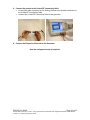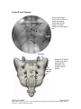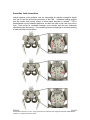
1
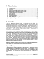
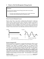
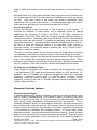
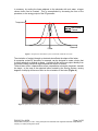
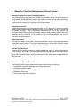
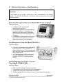
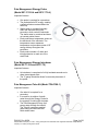
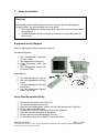
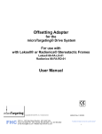
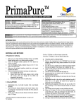
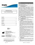
PM1013 Rev 09/08
Page 1 of 56
© Baylis Medical Company Inc. 2007. SInergy and Epsilon are trademarks and/or registered trademarks of Baylis Medical
Company Inc. Patents pending and/or issued.
1. Table of Contents
1.
2.
3.
4.
5.
6.
7.
8.
9.
10.
11.
12.
Table of Contents ................................................................................................2
Introduction..........................................................................................................2
Physics of the Pain Management SInergy System...............................................3
Benefits of the Pain Management SInergy System ..............................................7
Technical Description of the Equipment...............................................................8
Patient Selection................................................................................................10
Setup Instructions..............................................................................................11
Procedure Guidelines ........................................................................................17
Lesion Parameters.............................................................................................38
Generator Graphs During Treatment .............................................................41
Troubleshooting .............................................................................................45
References ....................................................................................................46
2. Introduction
The Pain Management SInergy System, in combination with the Baylis Pain
Management Generator (PMG-TD), is indicated for creating RF lesions in nervous tissue
to treat patients with sacroiliac joint complex mediated pain. The procedure is known as
sacroiliac joint radiofrequency neurotomy, and ablates the afferent nociceptive nerves
Target structures include the lateral branches of the S1 though S3 dorsal roots and the
dorsal ramus of the L5 dorsal root. These nerves are known to be responsible for
sacroiliac joint complex mediated pain.
In this procedure, a Pain Management SInergy Introducer is placed at a point between
the posterior sacral foramen and the sacroiliac joint. A Pain Management SInergy Probe
is inserted through the introducer and into the tissue superficial to the posterior surface
of the sacrum. Radiofrequency (RF) energy is delivered from and concentrated around
the electrode. The electrode is internally-cooled with circulating water. RF energy
heats the tissue while circulating water moderates the temperature in close proximity to
the electrode. This combination creates large volume lesions without excessive heating
at the electrode. Successive lesions are created by repositioning the introducer and
electrode in a step-wise manner, until all lateral branches between the sacral foramina
and the sacroiliac joint have been disrupted. For a list of equipment related to the Pain
Management SInergy System, see Section 5.
A physician using this equipment must be familiar with lumbar-sacral spine anatomy,
image-guided spine procedures and sacroiliac joint injection techniques.
Important Message
This guide does not replace the information in the Instructions for Use provided with the
components of the Pain Management SInergy System. The Instructions for Use
includes important information such as warnings, precautions, contraindications, and
trouble shooting. The Instructions for Use for each component must be read prior to
use.
PM1013 Rev 09/08
Page 2 of 56
© Baylis Medical Company Inc. 2007. SInergy and Epsilon are trademarks and/or registered trademarks of Baylis Medical
Company Inc. Patents pending and/or issued.
3.
Physics of the Pain Management SInergy System
Overview
This section briefly explains how the SInergy System heats nervous tissue.
In this section you will learn:
•
•
The reason why high frequency alternating current is used to heat tissue.
The reason why the SInergy Probes are internally-cooled.
Direct Current & Alternate Current
Electric current refers to the amount of charge that passes through a surface per
measure of time. At an atomic level, current is the flow of electrons. A current that
moves in the same direction around a circuit is referred to as Direct Current (DC). A
current whose direction alternates continuously back and forth is referred to as
Alternating Current (AC) (see Figure 1). The number of times that the current alternates
back and forth in a second is known as frequency. Frequency is measured in Hertz. For
example 60 Hertz means that the current alternates back and forth 60 times per second.
Current
Current
0
Time
Direct Current (DC)
0
Time
Alternate Current (AC)
Figure 1: Direct Current (DC) and Alternate Current (AC) signal amplitudes.
Resistive Heating with DC
Electrical conductance is the property of a material that determines the ability of current
to flow through it and is based on the availability of loose electrons in the material.
Resistance is the opposite of conductance. Copper wire, for instance has high
conductance and is a good conductor while rubber has low conductance and is a very
poor conductor. Since rubber is a poor conductor, this means that it is a good resistor.
In a resistor, as current passes through the material, energy is used. The harder it is to
pass current through a material, due to lower conductance, the more energy is used.
The energy that is used does not disappear but is converted to a different form of
energy, often in the form of heat. The conversion of electrical energy to thermal energy
by passing current through a material with resistance is called resistive heating. A good
example of resistive heating is an electric toaster. The metal filament in the toaster is
PM1013 Rev 09/08
Page 3 of 56
© Baylis Medical Company Inc. 2007. SInergy and Epsilon are trademarks and/or registered trademarks of Baylis Medical
Company Inc. Patents pending and/or issued.
made of nickel and chromium, which has an ideal resistance to convert electricity to
heat.
Biological tissue is not a very good conductor when using direct current. Resistive heat
can be generated but the flow of current cannot be controlled easily and it can damage
the cells. Using direct current to heat tissue may produce unpredictable tissue
temperatures and irregular shaped lesions. Excessive temperatures would lead to
burning of tissue, gas formation, and uncontrolled destruction of tissue10.
Ionic Heating with AC
Another way electrical energy is converted to heat in tissue is by ionic heating. To
overcome the drawback of direct current, use of alternating current for medical
applications was pioneered by Cushing and Bovie in the 1920s, originally for
hemostasis8. Later in the 1950s, Aranow and Cosman deployed alternating current for
creating neural lesions1. Alternating current conducts through tissue with less resistance
and more control than direct current. The greater the alternating current frequency, the
greater the conductance4. Alternating current causes the charged molecules, or ions, in
the tissue to follow the directional variation of the alternating current resulting in
molecular vibration. The molecular vibration produces heat due to frictional forces.7,9
This effect is called ionic heating.
The body is a complex system that uses electric current for a wide range of functions
from regulating a heart beat to sending the sense of touch from a finger to the brain. If
alternating current is applied to the body using frequencies similar to those used by the
body, it can interfere with physiological functions causing unwanted effects. This is
avoided by using a frequency beyond those used by the body. Alternating current with a
very high frequency, in the order of 500 kHz, does not affect physiological functions.
RF Generators in the Market Today
Today, modern AC generators use a frequency between 400 and 600 kilohertz which is
in the radiofrequency (RF) range and are generally referred to as RF generators. RF
generators are now equipped with automatic temperature control and impedance
monitoring. Temperature control allows for effective lesion formation whereas
impedance monitoring detects changes in tissue resistance to electric current.
Impedance monitoring also aids in electrode placement because impedance varies
between different tissues7,10
Monopolar Electrode Systems
Monopolar System Physics
In medical applications RF current is delivered to tissue by an electrode usually on the
end of a probe or insulated cannula. Ionic heating of tissue is a function of the current
density, or current per unit area. RF current flows out of the electrode radially, and as a
result, current density progressively decreases away from the electrode2. This is
illustrated in Figure 2, where a circle represents an electrode, and arrows represent the
current flowing radially from the electrode. The current, shown by the arrows is denser
in areas closer to the electrode. Consequently, ionic heating is greatest at the proximity
of the electrode and decreases with increasing distance. RF devices often contain
temperature sensors. Note that the electrode itself does not heat up. Instead the tissue
heats from ionic heating and the heat conducts back to the electrode10, where the sensor
indicates the tissue temperature local to the electrode. This decreasing gradient of
PM1013 Rev 09/08
Page 4 of 56
© Baylis Medical Company Inc. 2007. SInergy and Epsilon are trademarks and/or registered trademarks of Baylis Medical
Company Inc. Patents pending and/or issued.
current density limits the size of the heat lesion that can be produced. With a constant
power a heat lesion will only grow to a limited size because the amount of heat created
will come to equilibrium with the heat removed by the surrounding tissue and blood flow.
Figure 2: Current density, represented by arrows, around an electrode, represented by the circle. Note how the
tail ends of the arrows are more concentrated at the electrode and less dense as the arrows radiate away from
the electrode.
A way to increase the volume of tissue heated using RF is to increase the power.
However, increasing power also has its limitations. As power increases, so does the
temperature of the tissue in close proximity to the electrode. Exceeding 95°C may cause
cavitations, tissue charring, and uncontrolled lesion formation. It has been demonstrated
that tissue impedance (the measurement of tissue resistance to alternating current)
decreases as the temperature increases, up to 60 to 70°C; further increase in
temperature however, leads to a rapid increase in tissue impedance3. As tissue
impedance increases at high temperatures the further flow of current becomes more
difficult and harder to control.
Internally-Cooled RF Systems
Another means of increasing the volume of the lesion is by using internally-cooled RF
electrodes. This technique was first proposed by Wittkampf in 198812. The hollow
lumens of internally-water cooled probes permit continuous cooling of the electrode with
a fluid. Internally-cooled RF electrodes act as heat sinks that remove heat from tissue
adjacent to the electrode. Consequently, time, duration, or power deposition can be
increased during the procedure without causing high impedance and tissue charring
around the electrodes11. As a result, internally-cooled electrodes can produce much
larger lesions compared to non-cooled electrodes6. Furthermore, the tissue in proximity
to the electrode does not need to be as hot in order to reach target temperatures at
greater distances away from the electrode (Figure 3).
The water used for circulation in cooled RF lesions need only be room temperature.
When used for cooled RF, water temperatures of 5°C have been shown to not
significantly affect lesion size in ex vivo hepatic ablations compared to water
temperatures of 25°C5. However, increasing flow rate of the coolant has been
demonstrated to significantly affect lesion size13.
PM1013 Rev 09/08
Page 5 of 56
© Baylis Medical Company Inc. 2007. SInergy and Epsilon are trademarks and/or registered trademarks of Baylis Medical
Company Inc. Patents pending and/or issued.
In summary, by cooling the tissue adjacent to the electrode with cool water, a larger
volume lesion can be created. This is accomplished by increasing the time of the
procedure, or the energy output of the RF generator.
.
Temperature 80° C
Non-cooled
Cooled
45° C
Probe
Distance
Figure 3: Temperature distribution of non-cooled and cooled RF electrodes.
The circulation of coolant through an electrode also affects the shape of the lesion.
A monopolar cooled RF electrode, for example, can be designed to create a lesion that
is either spherical or elliptical in shape. A portion of this lesion can project distally from
the probe, heating tissue that might otherwise be difficult to access.
These distinct lesion characteristics allow perpendicular electrode placement towards
the target. In the case of the spherical lesion created by the SInergy System, varying
degrees of obliquity will have no effect on the orientation of the lesion (Figure 4).
Figure 4: Spherical lesions allow perpendicular or oblique placement towards the target structure.
PM1013 Rev 09/08
Page 6 of 56
© Baylis Medical Company Inc. 2007. SInergy and Epsilon are trademarks and/or registered trademarks of Baylis Medical
Company Inc. Patents pending and/or issued.
4. Benefits of the Pain Management SInergy System
Internally-Cooled for Greater Power Applications
The SInergy System electrodes are internally-cooled which allows for greater power to
be delivered. Increasing power enables the creation of large-volume, spherical lesions.
When these lesions are positioned appropriately, the inherent variability of nerve target
location can be overcome in a practical and efficient manner.
Temperature Control
Temperature sensors at the electrode tips allow the RF generator to control the power
delivery and the rate of internal electrode cooling. In this manner, lesion shape and size
will remain consistent. This is particularly important in an area of the anatomy that
contains multiple tissue types near the target structure. Note that the temperatures at the
electrode tips are reflective of the surface of the cooled electrodes, and not the
maximum lesion temperature.
Spherical Lesions
The spherical shape of the lesion allows perpendicular, oblique or parallel approaches
towards the target structure. The distally projecting portion of the lesion will form around
ridges, and within crevices on irregularly shaped surfaces.
Safe & Easy Placement
Placement of the SInergy probes is straight-forward and results in minimal disturbance
to the overlying soft tissue. Introducers and electrodes are directed at the target using a
“down the beam” perpendicular approach. To reposition towards adjacent targets, the
introducer is retracted slightly and pivoted about the skin, rather than creating additional
skin punctures.
Summary of System Benefits
The SInergy System creates reproducible, large volume lesions by utilizing:
• Temperature controlled radiofrequency energy application
• Internally-cooled electrodes
• Application specific electrode design
• Impedance monitoring
• User-friendly design and interface
PM1013 Rev 09/08
Page 7 of 56
© Baylis Medical Company Inc. 2007. SInergy and Epsilon are trademarks and/or registered trademarks of Baylis Medical
Company Inc. Patents pending and/or issued.
5. Technical Description of the Equipment
Overview
In this section you are going to learn about all of the components of the SInergy
System. You will learn the function of each device and the relationship of the device
within the system.
Baylis Pain Management Generator (Model PMG-TD V2.2 or higher)
Important features:
•
•
•
A software-based, computerized
radiofrequency generator.
Several safety features are incorporated into
the control algorithm. For example, the
generator can detect broken or improperly
set-up equipment and give appropriate error
messages.
It is designed to power and control the pump
unit, and provide automatically controlled
parameters designed for the procedure.
Pain Management Pump Unit (Model TDA-PPU-1)
Important features:
•
•
The pump unit circulates sterile water through
the SInergy Probe. This is achieved via
closed-loop fluid circuit. The closed-loop fluid
circuit includes a Pain Management Tube Kit
and a SInergy Probe.
The Pain Management Pump comes with a
connector cable which connects it to the
generator (PMG-TD) for power and speed
control.
Pain Management Cooled RF Connector
Cable (Model: CRX-BAY-CRP)
Important features:
•
•
•
•
Used to connect SInergy Probe to the generator.
Provides access to the Cooled RF mode in the generator.
Transmits RF energy from the generator to the probe.
Transmits signals from the temperature sensor in the probe to the generator.
PM1013 Rev 09/08
Page 8 of 56
© Baylis Medical Company Inc. 2007. SInergy and Epsilon are trademarks and/or registered trademarks of Baylis Medical
Company Inc. Patents pending and/or issued.
Pain Management SInergy Probe
(Model SIP-17-150-4 and SIP-17-75-4)
Important features:
•
•
•
•
•
One probe is required for a procedure.
The probe delivers RF energy, creating
a spherical lesion centered about the
active tip.
Sterile water is circulated internally
within the electrode during the
procedure, which cools the electrode.
The sterile water is contained and does
not contact patient tissue.
Each probe has a temperature sensor at
the distal end of the electrode. The
temperature sensor measures
temperature and provides control of RF
energy delivery throughout the
procedure.
Each probe includes a 4’ cable and
tubing extension to reach out of the
sterile field.
Pain Management SInergy Introducer
(Model SII-17-150 and SII-17-75)
Important features:
•
•
An introducer is comprised of a fully-insulated cannula and a
sharp trocar-tipped stylet.
The 17-gauge introducer allows for accurate placement of
the probe.
Pain Management Tube Kit (Model TDA-TBK-1)
Important features:
•
•
•
One tube kit is required for a
procedure.
It is used for circulation of sterile
water through the SInergy Probe for
the purpose of cooling the electrode.
The Pain Management Pump Unit
pumps water through the tube kit.
The Tube Kit comprises medical
grade tubing and a burette that
holds sterile water.
PM1013 Rev 09/08
Page 9 of 56
© Baylis Medical Company Inc. 2007. SInergy and Epsilon are trademarks and/or registered trademarks of Baylis Medical
Company Inc. Patents pending and/or issued.
Pain Management Epsilon™ Ruler
(Model SIA-E10)
Important Features:
•
•
Open, circular, stainless steel ruler with a 10 mm
radius and 10 mm central spoke length.
Used during the procedure to measure a safe
distance between the sacral foramina and the
electrode.
6. Patient Selection
Candidates for sacroiliac joint neurotomy must have a history of chronic sacroiliac joint
complex pain for at least 6 months, and meet the selection criteria. It is important to
adhere to these criteria for the safety of the patient and success of the treatment. The
physician must be trained to diagnose sacroiliac joint complex mediated pain.
Selection Criteria
Candidates for the Sacroiliac Joint Neurotomy procedure must meet the following
inclusion criteria.
• Predominantly axial pain below the L5 vertebrae
• Greater than 80% pain relief from two separate intra-articular blocks with no more
than 2cc of injectate per block. It is recommended to use higher concentration
anesthetic such as 0.75% bupivacaine or 4% lidocaine for a more effective block.
• Chronic axial pain lasting for longer than six months.
• Age greater than 18 years.
• Failed to achieve adequate improvement with comprehensive non-operative
treatments, including but not limited to: activity alteration, non-steroidal antiinflammatory, physical and/or manual therapy, and fluoroscopically guided steroid
injections in and around the area of pathology.
• All other possible sources of low back pain have been ruled out, including but not
limited to: the intervertebral discs, the zygapophyseal joints, the hip joint, symptomatic
spondylolisthesis, and other regional soft tissue structures.
Candidates for the Sacroiliac Joint Neurotomy procedure will be excluded if they meet
any of the following criteria:
•
•
•
•
•
•
Pregnancy
Systematic infection or localized infection at the anticipated introducer entry site
History of coagulopathy or unexplained bleeding
Irreversible psychological barriers to recovery
Active radicular pain / radiculopathy
Immunosuppression
PM1013 Rev 09/08
Page 10 of 56
© Baylis Medical Company Inc. 2007. SInergy and Epsilon are trademarks and/or registered trademarks of Baylis Medical
Company Inc. Patents pending and/or issued.
7. Setup Instructions
Overview
The following section outlines the procedure for setting up the Pain Management
SInergy System. We have provided two set-up guides:
• Quick Start Equipment Set-Up designed for users who have previously handled
the equipment.
• Detailed Equipment Set-Up designed for users who are using the system for
the first time.
Equipment Set-Up Diagram
The Pain Management SInergy System consists of:
Reusable Equipment:
1. Pain Management Generator
V2.2A or higher
2. Pain Management Pump Unit
3. Pump Connecting Cable (not
shown)
4. Pain Management Cooled RF
Connector Cable
Disposable Kit:
5. One Pain Management Tube Kit
6. One Pain Management SInergy
Probe
7. Two Pain Management SInergy
Introducers
8. Two Pain Management Epsilon
Rulers (not shown)
1
2
5
4
7
6
Quick Start Equipment Set-Up
1.
2.
3.
4.
5.
6.
7.
8.
Connect the Generator to the Pump Unit
Plug in the Generator and turn it on
Insert one Pain Management Tube Kit into the Pain Management Pump Unit
Fill the burette with sterile water
Connect the Cooled RF Connecting Cable to the Generator
Place the introducer and probe in the patient.
Connect probes to Pain Management Tube Kit
Connect the probe to the Cooled RF Connecting Cable
PM1013 Rev 09/08
Page 11 of 56
© Baylis Medical Company Inc. 2007. SInergy and Epsilon are trademarks and/or registered trademarks of Baylis Medical
Company Inc. Patents pending and/or issued.
Detailed Equipment Set-Up
1. Connect the Generator to the Pain Management Pump Unit
• Connect the male connector of the Pain Management Pump Connector Cable to
the generator.
• Connect the female connector of the Pain Management Pump Connector Cable
to the Pump Unit.
• Push the connectors as far in as possible, and then tighten by turning the collar
clockwise.
2. Plug in the Generator
• Plug the power cord into the Pain Management Generator, and connect the
generator directly to a grounded receptacle.
• Turn the generator on.
PM1013 Rev 09/08
Page 12 of 56
© Baylis Medical Company Inc. 2007. SInergy and Epsilon are trademarks and/or registered trademarks of Baylis Medical
Company Inc. Patents pending and/or issued.
3. Insert Tube Kits into the Pain Management Pump Unit
• Remove the Pain Management Tube Kit from the sterile package.
• Put the burette into the Pump Unit’s burette holder.
• Open the pump head lid and thread the thicker tubing from the bottom of the
burette into the pump head tube holder.
• Ensure that the tubing is properly placed between the notches and along the
center channel beneath the pump head. Improper positioning of the tubing can
pinch the tube and restrict the water flow.
• Close the lid in order to hold the tubing in place. Leave the luer lock caps on the
tubing until you are ready to connect the probes so the inner pathway of the tube
kit remains sterile.
Burette
Burette Holder
Pump Head Lid
Center
Channel
PM1013 Rev 09/08
Notches
Pump Head
Thick tubing
Page 13 of 56
© Baylis Medical Company Inc. 2007. SInergy and Epsilon are trademarks and/or registered trademarks of Baylis Medical
Company Inc. Patents pending and/or issued.
4. Fill the burette with sterile water
Fill the burette to the 70 mL mark with room temperature sterile water by a) injecting
through the port in the lid or b) removing the lid and pouring the sterile water into the
burette.
a) Inject sterile water through the port in the lid
• Remove the cap of the burette.
• Using a sterile syringe, fill the burette with 70 ml of sterile water at room
temperature.
b) Remove the lid and pour sterile water into the burette
• Open the lid by pressing in and up with your thumbs around one of the three
petals.
• Observe proper sterile handling technique while filling the burette; do not place
the lid of the burette down on a non sterile surface.
• The fill lines on the burette represent 70mL and 80mL respectively.
• After filling to between the lines, snap the lid back into place on the burette.
• Note that not all burettes have removable lids. In this case, fill the burette by
injecting water through the port in the lid.
Upper (80mL) and
Lower (70mL) Fill
Lines
PM1013 Rev 09/08
Page 14 of 56
© Baylis Medical Company Inc. 2007. SInergy and Epsilon are trademarks and/or registered trademarks of Baylis Medical
Company Inc. Patents pending and/or issued.
5. Place the introducer and probe in the patient
• Prepare the patient and place the SInergy Introducer and Probe– See Section 8
for Placement Guidelines.
6. Place the Dispersive Electrode on the patient
• Place the Dispersive Electrode on the patient according to the Instructions for
Use provided with the kit.
7. Connect probes to Pain Management Tube Kits
• Pass the tubing and electrical connections on the probe out of the sterile field.
• Remove the caps from the two luer locks on the SInergy Probe and the Tube Kit.
Connect the luer locks snugly. Maintain sterility of the tubing’s inner pathway so
in case water is accidentally spilled in the sterile field, sterility will not be
compromised.
Luer Lock Cap
Luer Lock
PM1013 Rev 09/08
Page 15 of 56
© Baylis Medical Company Inc. 2007. SInergy and Epsilon are trademarks and/or registered trademarks of Baylis Medical
Company Inc. Patents pending and/or issued.
8. Connect the probes to the Cooled RF Connecting Cable
• Connect the male connectors on the SInergy Probes to the female connectors on
the Cooled RF Connecting Cable.
• Connect the Cooled RF Connecting Cable to the generator
9. Connect the Dispersive Electrode to the Generator
Now the equipment set-up is complete!
PM1013 Rev 09/08
Page 16 of 56
© Baylis Medical Company Inc. 2007. SInergy and Epsilon are trademarks and/or registered trademarks of Baylis Medical
Company Inc. Patents pending and/or issued.
8. Procedure Guidelines
Overview
This section describes the positioning of the introducers and probe within the patient.
In this section you will learn:
•
•
•
The general safety guidelines for placement
Brief lumbar-sacral anatomy with fluoroscopic and photographic images
Step-by-step placement technique
General Safety Guidelines
For safe and effective tissue heating and safe anatomical access abide by the following
guidelines:
• For L5 dorsal ramus neurotomy the electrode should be directed at the dorsal surface
of the notch between the sacral ala and the superior articular process of the sacrum.
On a lateral fluoroscopic view, the introducer should be no further ventral than the
anterior-posterior midline of the superior articular process (SAP). Placement more
superior/ventral to the target point brings the electrode closer to the segmental nerve
root, and increases the risk of inadvertent heating of this structure.
• For S1 – S3 lateral branch neurotomy, the electrode should be placed such that the
active tip is at least 7 mm from the edge of nearest posterior sacral foramina. This
electrode placement will ensure that there is no heating at the sacral canal. Electrode
depth should be confirmed with lateral fluoroscopy prior to lesion creation. This will
verify that the electrode is located superficial to the sacral surface, and confirm that it
has not slipped into the nearest posterior foramen.
• For all targets, the introducer should be directed towards the target site until the tip is
in contact with bone. When the stylet is removed and the electrode is inserted, there
will be a 2 mm gap between the active tip and bony endpoint. This will achieve the
appropriate electrode depth for treatment. Ensure that the probe is seated firmly in
the introducer before proceeding.
• The stylet should always be replaced in the introducer prior to repositioning. The
electrode is not designed to create new pathways through the dense connective
tissue along the surface of the sacrum.
• Ensure that the electrode does not make physical contact with the “finder” needle
during RF delivery.
PM1013 Rev 09/08
Page 17 of 56
© Baylis Medical Company Inc. 2007. SInergy and Epsilon are trademarks and/or registered trademarks of Baylis Medical
Company Inc. Patents pending and/or issued.
Lumbo-Sacral Anatomy
Fluoroscopic Image:
This is an A-P view of a
lumbo-sacral spine,
showing the SI joint
margin, the sacral
foramina, and the sacral
ala
Sacral Ala
S1
S2
SI Joint
Margin
S3
Sacral Ala
S1
S2
SI Joint
Margin
Illustration of Sacrum:
Compare the above
image with this
illustration of the
posterior sacral
surface.
S3
PM1013 Rev 09/08
Page 18 of 56
© Baylis Medical Company Inc. 2007. SInergy and Epsilon are trademarks and/or registered trademarks of Baylis Medical
Company Inc. Patents pending and/or issued.
Sacroiliac Joint Innervation
Lateral branches of the posterior rami are responsible for relaying nociceptive signals
from the SIJ and the surrounding structures to the CNS. Anatomical studies suggest
that the number and running course of these lateral branches is variable14. This is
demonstrated not only between specimens, but also from side to side, and from level to
level. There exists no correlation between nerve location and the bony landmarks
identifiable under fluoroscopy. This variability presents a challenge for clinicians seeking
to treat sacroiliac joint syndrome.
PM1013 Rev 09/08
Page 19 of 56
© Baylis Medical Company Inc. 2007. SInergy and Epsilon are trademarks and/or registered trademarks of Baylis Medical
Company Inc. Patents pending and/or issued.
Procedure Preparation
• The patient should be N.P.O. prior to the procedure. Bowel prep is encouraged for
enhanced imaging quality, but is optional based on physician preference.
Prophylactic antibiotics can be administered prior to the procedure based on
physician preference. Place the patient in the prone position on the table.
• The patient must be monitored properly throughout the procedure using verbal
communication as well as equipment to measure heart rate, blood oxygen level, and
blood pressure.
• As with any minimally invasive technique, adhere to sterile procedural practices.
• Prepare the site with sterile draping to maintain sterility of the lower lumbar and sacral
area.
• The procedure is conducted with the aid of fluoroscopic guidance. Precautions
should be taken to minimize exposure to radiation.
• Ensure the patient is comfortable and the appropriate pharmacological pain therapy
has been administered. This may constitute intravenous sedation, oral analgesics, or
other methods depending on physician and institution preference. The patient should
be relaxed and able to communicate throughout the procedure. General anesthesia
should be avoided.
PM1013 Rev 09/08
Page 20 of 56
© Baylis Medical Company Inc. 2007. SInergy and Epsilon are trademarks and/or registered trademarks of Baylis Medical
Company Inc. Patents pending and/or issued.
Sacroiliac Joint Neurotomy: Procedural Technique
A technique for lesioning the lateral branches of the S1 thru S3 dorsal roots using the
Pain Management SInergy System is provided.. Subsequent pages detail a technique
for lesioning the L5 dorsal ramus using the same equipment.. Fluoroscopic images
provided courtesy of Dr. Robert E. Wright, Denver Pain Management, and Dr. Paul
Dreyfuss, Washington Interventional Spine Associates.
Sacroiliac Joint Neurotomy: S1 – S3 Lateral Branches
1. Obtain an anterior-posterior (A-P) fluoroscopic image by aligning the L5-S1 vertebral
end plates. The S1, S2 and S3 posterior sacral foramina should be identifiable. If not,
the image can be rotated 10-15 degrees in the ipsilateral direction, or as required, in
order to better visualize the posterior sacral foramina.
PM1013 Rev 09/08
Page 21 of 56
© Baylis Medical Company Inc. 2007. SInergy and Epsilon are trademarks and/or registered trademarks of Baylis Medical
Company Inc. Patents pending and/or issued.
2. A thin-gauge needle is gently placed along the
inside lateral aspect of each S1, S2 and S3 sacral
foramina until it has entered the posterior aspect of
the sacral canal. The purpose of this finder needle is
to act as a reference point for the placement of the
introducer and the probe in the absence of reliable
bony landmarks.
LEFT
PM1013 Rev 09/08
RIGHT
Page 22 of 56
© Baylis Medical Company Inc. 2007. SInergy and Epsilon are trademarks and/or registered trademarks of Baylis Medical
Company Inc. Patents pending and/or issued.
3. It is important to confirm that the finder needles are in the sacral foramina by rotating
to a lateral fluoroscopic view. The tip of the needle should be visible in the sacral canal.
The finder needles are then withdrawn until the tip of each needle is marking the
posterior aspect (or opening) of the sacral canal.
Finder Needles
PM1013 Rev 09/08
Page 23 of 56
© Baylis Medical Company Inc. 2007. SInergy and Epsilon are trademarks and/or registered trademarks of Baylis Medical
Company Inc. Patents pending and/or issued.
4. Obtain an A-P fluoroscopic image. Place
an Epsilon ruler on the skin near the
insertion site such that the central spoke is
aligned with the lateral border of the S1
foramen, as marked by the tip of the finder
needle.
The Epsilon ruler is a small
stainless steel ruler which projects linear
distance onto the sacrum and provides a
reference for appropriate lesion spacing.
Surgical tape can be used to help secure the
Epsilon to the surface of the skin. Consider
the tip of the marker needle as representing
the center of a clock face. Rotate the
Epsilon ruler around this point such that the
upper spoke is marking a location equivalent
to 2:30 for right sided treatment, or 9:30 for
left sided treatment.
LEFT
RIGHT
IMPORTANT NOTE: Similar to other fluoroscopic measurement techniques, the Epsilon
ruler will experience some degree of parallax error. This is because the sacrum and the
Epsilon are at different ‘depths’ with respect to the image intensifier. To minimize yparallax error (experienced as distortion of the shape of the ruler when it is tilted) both
the Epsilon ruler and the patient’s sacrum should be perpendicular to the beam of the
emitter during placement. In other words, the Epsilon should be flat on the patient’s
skin, and the image should be A-P.
PM1013 Rev 09/08
Page 24 of 56
© Baylis Medical Company Inc. 2007. SInergy and Epsilon are trademarks and/or registered trademarks of Baylis Medical
Company Inc. Patents pending and/or issued.
5. The first target location with the Cooled-RF
probe is 7 to 10mm lateral and slightly inferior
to the S1 finder needle. On the clock face,
this corresponds to a 4 o’clock position (8
o’clock for left sided treatment). With the use
of the Epsilon ruler as a guide, direct the
introducer perpendicularly, “down the beam”
until the stylet has made firm contact with the
dorsal sacral surface.
Note that the
ligamentous tissue along the surface of the
sacrum can be dense and difficult to
penetrate.
LEFT
S1 8:00
PM1013 Rev 09/08
RIGHT
S1 4:00
Page 25 of 56
© Baylis Medical Company Inc. 2007. SInergy and Epsilon are trademarks and/or registered trademarks of Baylis Medical
Company Inc. Patents pending and/or issued.
6. Confirm the depth of the stylet and introducer by rotating the image to a lateral view.
The stylet and introducer should be at the sacral surface and must not have slipped into
the sacral foramina. Not infrequently, especially at S1, one needs to advance further
through very tough tissue to obtain the target position.
PM1013 Rev 09/08
Page 26 of 56
© Baylis Medical Company Inc. 2007. SInergy and Epsilon are trademarks and/or registered trademarks of Baylis Medical
Company Inc. Patents pending and/or issued.
7. Rotate the C-arm back to an A-P view. Remove the stylet from the introducer. A
small volume (less that or equal to 1cc) of local anesthetic is optionally administered to
the target site through the introducer. Place the SInergy Probe into the introducer,
ensuring that it is seated snuggly in the hub. Note that the SInergy Probe is 2 mm
shorter that the stylet. The probe is designed to sit 2 mm off of the dorsal sacral surface
to ensure that the thermocouple is not shielded in bone, and that the lesion does not
extend unnecessarily into the periosteum. The impedance displayed on the screen of
the Pain Management Generator should not exceed 500 ohms. Impedance values
exceeding 500 ohms may indicate that the probe is positioned in tissue not suitable for
lesioning, or that the probe is not fully seated in the hub of the introducer. The position of
the probe is secured by sliding the green ‘depth’ stopper down to the surface of the skin.
Sacral Surface
PM1013 Rev 09/08
Sacral Surface
Sacral Surface
Page 27 of 56
© Baylis Medical Company Inc. 2007. SInergy and Epsilon are trademarks and/or registered trademarks of Baylis Medical
Company Inc. Patents pending and/or issued.
8. Create the first lesion according the parameters outlined in Lesion Parameters;
Section 9 of this document. Suggested parameters include Set Temperature = 60°C,
Time = 2:30. Monitor the patient’s response during lesioning for non-concordant pain in
the groin, anterior thigh, lower leg, or foot. The lesion can be stopped at any time by
depressing the ON/OFF button on the lower right corner of the pain generator.
PM1013 Rev 09/08
Page 28 of 56
© Baylis Medical Company Inc. 2007. SInergy and Epsilon are trademarks and/or registered trademarks of Baylis Medical
Company Inc. Patents pending and/or issued.
10. After the first lesion is complete, remove the
probe from the introducer, and replace it with the
stylet. This is important as the probe is not
designed to penetrate tough connective tissue.
Directing the probe through connective tissue may
render it inoperative. The second target site is 710 mm superior and lateral to the tip of the S1
finder needle. On the clock face, this corresponds
to a 2:30 position (9:30 position on the left side),
and should be marked by the upper spoke of the
Epsilon ruler. The introducer and stylet are then
redirected towards the second target site by
withdrawing slightly, and pivoting about the skin.
In this manner, the original skin puncture can be
used as a pivot point for the second and third
targets. Confirm electrode placement and create
a lesion using the same procedures described
previously.
LEFT
S1 9:30
PM1013 Rev 09/08
RIGHT
S1 2:30
Page 29 of 56
© Baylis Medical Company Inc. 2007. SInergy and Epsilon are trademarks and/or registered trademarks of Baylis Medical
Company Inc. Patents pending and/or issued.
11. Remove the probe and replace the stylet in
the introducer. The third target site is 7-10 mm
inferior and lateral to the finder needle. On the
clock face, this corresponds to a 5:30 position
(6:30 position on the left side), and should be
marked by the lower spoke of the Epsilon ruler.
Once again, the original skin puncture can be
used as a pivot point. Withdraw the introducer
slightly, and direct it towards the target.
Confirm electrode placement and create a
lesion using the same procedures described
previously.
LEFT
RIGHT
S1 6:30
S1 5:30
PM1013 Rev 09/08
Page 30 of 56
© Baylis Medical Company Inc. 2007. SInergy and Epsilon are trademarks and/or registered trademarks of Baylis Medical
Company Inc. Patents pending and/or issued.
12. The same sequence of steps is repeated to create a lateral
arc of treated tissue around the S2 dorsal foramen, lesioning
at the 4 o’clock, 2:30 o’clock and 5:30 o’clock positions (8
o’clock, 9:30 o’clock and 6:30 o’clock positions on the left
side).
LEFT
LEFT
LEFT
S2 8:00
S2 9:30
S2 6:30
RIGHT
RIGHT
RIGHT
S2 4:00
S2 2:30
S2 5:30
PM1013 Rev 09/08
Page 31 of 56
© Baylis Medical Company Inc. 2007. SInergy and Epsilon are trademarks and/or registered trademarks of Baylis Medical
Company Inc. Patents pending and/or issued.
13. The same sequence of steps is also repeated to
create a lateral arc of tissue around the S3 dorsal
foramen, this time only lesioning at the 2:30 o’clock and 4
o’clock positions (9:30 o’ clock and 8 o’clock positions on
the left side).
LEFT
S3 8:00
RIGHT
S3 4:00
PM1013 Rev 09/08
LEFT
S3 9:30
RIGHT
S3 2:30
Page 32 of 56
© Baylis Medical Company Inc. 2007. SInergy and Epsilon are trademarks and/or registered trademarks of Baylis Medical
Company Inc. Patents pending and/or issued.
14. After completing the lesions at S3
there is a continuous band of ablative
lesions between the sacral foramina and
the sacroiliac joint.
L5 Dorsal Ramus Neurotomy
15. Needle placement for this procedure is similar to that for a diagnostic lumbar medial
branch block at the same level. The target location is the notch between the ala of the
sacrum and the superior articular process (SAP) of the sacrum. This corresponds to the
known running course of the L5 dorsal ramus.
Sacral Ala
S1 SAP
TARGET
S1 Foramen
PM1013 Rev 09/08
Page 33 of 56
© Baylis Medical Company Inc. 2007. SInergy and Epsilon are trademarks and/or registered trademarks of Baylis Medical
Company Inc. Patents pending and/or issued.
16. The target point lies at the base of the SAP
along its lateral midline. This corresponds to a
point in the notch where the surface of the bone
is still dorsally facing (before it curves ventrally
towards the intervertebral foramen). The target
point is visualized using an anterior/posterior
(AP) fluoroscopic view. The puncture point on
the skin is just lateral and inferior to the target.
Adjustments to the puncture point can be made
to ensure that the needle course is medial to the
iliac crest. The introducer is advanced until
contact is made with the target bony endpoint.
Under AP view, the tip of the needle should be
up against the base of the SAP and under its
lateral margin.
Note that needle placement is on the dorsal
surface of the bone.
Placement more
superior/ventral to the target point brings the
electrode closer to the segmental nerve root, and
increases the risk of inadvertent heating of this
structure.
LEFT
PM1013 Rev 09/08
RIGHT
Page 34 of 56
© Baylis Medical Company Inc. 2007. SInergy and Epsilon are trademarks and/or registered trademarks of Baylis Medical
Company Inc. Patents pending and/or issued.
17. Rotation to an oblique view should confirm correct location of the stylet tip at the
target point. Reposition as necessary to obtain appropriate needle position.
LEFT
18. A lateral view is obtained to confirm
depth of needle placement. The tip of
the stylet should be no deeper than the
AP midline of the SAP, which can be
approximated by the joint space of the
L5/S1 zygopophysial joint.
RIGHT
LATERAL
Max. Insertion depth
L5/S1 z-joint space
PM1013 Rev 09/08
Page 35 of 56
© Baylis Medical Company Inc. 2007. SInergy and Epsilon are trademarks and/or registered trademarks of Baylis Medical
Company Inc. Patents pending and/or issued.
19. Remove the stylet from the introducer. A
small volume (less that or equal to 1cc) of local
anesthetic is optionally administered to the
target site through the introducer. Place the
SInergy Probe into the introducer, ensuring that
it is seated snuggly in the hub. On lateral view
the tip of the probe should be 2 mm proximal to
the tip position previously observed for the stylet.
This is to accommodate the distal project of the
lesion from the tip of the electrode.
LATERAL
Note that there will be up to 4mm of distal lesion
projection from the tip of the electrode. Ensure
there is adequate distance between the tip of the
electrode and the foramen of the L5 segmental
nerve root to minimize the risk of inadvertent
heating to this structure.
20. A lesion is created around the tip of the electrode
as
previously
described.
Suggested
lesion
parameters remain unchanged; Set Temperature =
60°C, Time = 2:30 Monitor the patient’s response
during lesioning for non-concordant pain in the groin,
anterior thigh, lower leg, or foot. The lesion can be
stopped at any time by pressing the ON/OFF button
on the lower right corner of the pain generator.
PM1013 Rev 09/08
Page 36 of 56
© Baylis Medical Company Inc. 2007. SInergy and Epsilon are trademarks and/or registered trademarks of Baylis Medical
Company Inc. Patents pending and/or issued.
21. Optionally, perform a second lesion at the
base of the superior articular process of the
sacrum, 6-8mm inferior to the first lesion
location.
Post-Procedure Care
Discharge Instructions on the day of the procedure
• Do not drive or operate machinery
• Do not engage in any strenuous activity
• Do not soak in the bathtub, but a shower is okay
• Eat a regular diet
• You may remove bandages the following day
• You may use an ice pack today and warm moist heat tomorrow if you experience
discomfort when the local anesthetic wears off.
• If you experience fever, chills or severe pain at accompanied by swelling and
redness at the injection site, contact your treating physician.
• If you experience shortness of breath or chest pains go to the nearest emergency
room.
Activity Guidelines
• Resume normal activities as tolerated the day after the procedure.
• Avoid excessive activity, lifting, or other forms of increased physical activity for 1-3
days following the procedure.
PM1013 Rev 09/08
Page 37 of 56
© Baylis Medical Company Inc. 2007. SInergy and Epsilon are trademarks and/or registered trademarks of Baylis Medical
Company Inc. Patents pending and/or issued.
9. Lesion Parameters
Overview
This section describes the parameters used to control the heating profile during the
procedure. In this section you will learn:
•
•
•
What the modifiable parameters are
How the parameters affect the heating
Suggested parameters to use
Parameters used to create heating profile
The parameters available to control the heating profile are:
Ramp Rate
Set Temperature
Time
80
70
Set Temperature
(°C)
60
Temperature (°C)
50
40
Ramp Rate
(°C/minute)
30
Duration
(minutes)
20
0
1
Time (min)
2
There is a temperature sensor at the tip of the SInergy Probe. The generator will
monitor this temperature sensor and automatically deliver the required power to raise the
temperature of the target tissue. The shape of the heating profile is determined by the
parameters Ramp Rate, Set Temperature, and Time. At the beginning of the
procedure the temperature is lower than body temperature because the pumps are
running and cooling has begun. The probe temperature will increase at the Ramp Rate
PM1013 Rev 09/08
Page 38 of 56
© Baylis Medical Company Inc. 2007. SInergy and Epsilon are trademarks and/or registered trademarks of Baylis Medical
Company Inc. Patents pending and/or issued.
until it reaches the Set Temperature.
Temperature until the Time is complete.
The temperature will remain at the Set
Effect of Parameters
Ramp Rate is the rate of increase in temperature per minute (as measured by the
probe’s temperature sensor). A slower Ramp Rate results in better control of heating,
larger volumes of heated tissue, and more consistent temperature profile. A faster
Ramp Rate results in shorter procedure time.
In conventional non-cooled RF
procedures such as a z-joint rhizotomy, the ramp rate is usually about 15 seconds. The
optimum ramp rate for the SInergy System is only slight longer, lasting 25 seconds. It
must be understood that this time has been optimized to balance procedural speed, and
lesion consistency. Ramp Rate can only be changed in the Advanced Settings of the
generator.
Set Temperature is the desired temperature of the probe’s electrode surface. The
temperature will increase at the Ramp Rate until it reaches the Set Temperature which is
then maintained. Due to the cooling of the electrodes, the Set Temperature will be 1015° Celsius lower than the tissue a few millimeters from the electrode. The level of the
Set Temperature in combination with the Ramp Rate and Time will affect the
temperature throughout the tissue. Set Temperature can be changed at any time before
or during the RF delivery.
Time is the duration of radiofrequency energy delivery, including the temperature ramp
up and plateau. A longer Time will allow a greater volume of tissue to be heated until
thermal equilibrium is reached. The optimum Time is long enough for adequate volume
heating without excessive procedure time. Time can be changed at any time before or
during the RF delivery.
Power Limit is the maximum power (in Watts) that the generator will output at any time
during the procedure. Power output will vary throughout the procedure as required to
achieve the desired Ramp Rate and Set Temperature. Typically, power values are
higher during the temperature ramp and lower once the probe has reached Set
Temperature. If the Power Limit is reached during temperature ramp, the generator will
continue to deliver RF at this maximum value. This may increase the Ramp Rate by
several seconds, but will ensure that the lesion forms in a safe and consistent manner.
If the Power Limit is set too high, it is possible to have irregular lesion shapes or
excessive heating.
Refer to the following page for the suggested lesion parameters.
PM1013 Rev 09/08
Page 39 of 56
© Baylis Medical Company Inc. 2007. SInergy and Epsilon are trademarks and/or registered trademarks of Baylis Medical
Company Inc. Patents pending and/or issued.
Suggested Parameters
The suggested parameters used for treating a patient with the SInergy System are:
Set Temperature = 60 ºC
Ramp Rate = 80 ºC/min
Time = 2:30 minutes
These parameters were tested and scrutinized through a series of bench tests and in
vivo experiments. The experiments were designed to map temperatures in the tissue
and in the surrounding neural structures to ensure that heat was applied in a manner
suitable for both efficacy and safety during treatment.
For practical use, set the Advanced Settings on the generator as follows:
Ramp Rate = 80°C/min
Post Treatment Cooling = Disable
Number of Probes = 1
Power Limit = 12 Watts
PM1013 Rev 09/08
Page 40 of 56
© Baylis Medical Company Inc. 2007. SInergy and Epsilon are trademarks and/or registered trademarks of Baylis Medical
Company Inc. Patents pending and/or issued.
10. Generator Graphs During Treatment
Overview
This section shows images of generator screens to explain what a typical procedure
looks like compared to an abnormal procedure. In this section you will learn:
•
•
Appearance of a typical procedure graph.
Appearance of an abnormal procedure graph.
The figures in this section represent screens of a Baylis Pain Management Generator
(Model PMG-115-TD and PMG-230-TD, V2.2A). Refer to the generator’s user manual
for complete details.
The graph on the generator shows the temperature (“COOLED RF TEMP” in yellow),
and the power (“POWER” in magenta). An ideal procedure graph, as shown below, has
fairly smooth lines with the COOLED RF TEMP rising steadily until the SET
TEMPERATURE (dashed yellow line) is reached. The POWER will increase until the
COOLED RF TEMP reaches SET TEMPERATURE. Following this the POWER may
plateau, or decrease slightly over the remainder of the procedure. Typical POWER
values range from 2 to 12 Watts.
Generator graph of an ideal procedure.
PM1013 Rev 09/08
Page 41 of 56
© Baylis Medical Company Inc. 2007. SInergy and Epsilon are trademarks and/or registered trademarks of Baylis Medical
Company Inc. Patents pending and/or issued.
The graph in on this page is similar to the ideal graph except there is a small blip in both
lines at about 1 minute. This is commonly seen if the patient moves to get more
comfortable or coughs. It may also be seen if the probe is bumped or moved. This is
likely not a problem but it is a good idea to check the lateral and AP fluoroscopy views to
make sure the probe is still in a desirable position.
Generator graph showing a small blip is okay.
PM1013 Rev 09/08
Page 42 of 56
© Baylis Medical Company Inc. 2007. SInergy and Epsilon are trademarks and/or registered trademarks of Baylis Medical
Company Inc. Patents pending and/or issued.
The graph in on this page is also similar to the ideal graph, except that the POWER has
reached the power limit of 12W for a short period of time during the beginning of the
procedure. As a result, it has taken about 15 seconds longer than usual for the
COOLED RF TEMP to reach SET TEMPERATURE. This is periodically seen when the
probe has been placed in particularly dense connective tissue. The power limit has
ensured that the lesion formed in a safe and uniform manner.
If the SET
TEMPERATURE is unable to reach SET TEMPERATURE because of this feature, stop
the procedure and reposition the electrode.
Generator graph showing that reaching the power limit is okay.
PM1013 Rev 09/08
Page 43 of 56
© Baylis Medical Company Inc. 2007. SInergy and Epsilon are trademarks and/or registered trademarks of Baylis Medical
Company Inc. Patents pending and/or issued.
An example of a graph that indicates a poor procedure is shown below. The COOLED
RF TEMP and POWER lines have become erratic, indicating that the electrode is not
able to deliver RF energy in a consistent manner for this tissue location. This will likely
be accompanied by a higher that normal impedance reading (> 500 Ω). This may be
caused by tissue inhomogeneity around the active tip of the electrode, or by placing the
active tip in dense connective tissue or bone. Immediately stop the procedure and
reposition the electrode.
Generator graph of a poor procedure.
PM1013 Rev 09/08
Page 44 of 56
© Baylis Medical Company Inc. 2007. SInergy and Epsilon are trademarks and/or registered trademarks of Baylis Medical
Company Inc. Patents pending and/or issued.
11. Troubleshooting
Overview
In this section you will:
•
•
Learn how to identify potential problems with system components
Become familiar with the Generator Error and Fault Codes that may appear
during a SInergy procedure
Trouble-Shooting Pain Management SInergy System Components
In addition to the information contained within this document, each SInergy Kit has a
troubleshooting table in its Instructions for Use to assist the user in diagnosing potential
problems.
PM1013 Rev 09/08
Page 45 of 56
© Baylis Medical Company Inc. 2007. SInergy and Epsilon are trademarks and/or registered trademarks of Baylis Medical
Company Inc. Patents pending and/or issued.
Discard the tube kit.
Pain Management Tube Kit
Pain Management Tube Kit
© Baylis Medical Company Inc. 2007. SInergy and Epsilon are trademarks and/or registered trademarks of Baylis Medical Company Inc. Patents pending and/or issued.
Page 46 of 56
Using a syringe, pressurize the section of tube kit tubing that terminates in a female
lure lock.
Inject sterile water through the port in the lid, rather than removing the lid.
SInergy Probe and Pain
Management Tube Kit
Pump Unit and Pain
Management Tube Kit
Pain Management Tube Kit
Ensure that the connectors are clean and unobstructed.
Check that the connector's keys are lined up in the proper orientation. Turn the
connector until it slides in the mating connector.
Do not use damaged equipment.
Discard the device if packaging has been compromised.
Visually inspect the products for any damage. Look for damage such as cuts,
cracks, breaks, and bends.
Trouble-Shooting Actions
Visually inspect the packaging before use. The sterile pouch should not have any
holes.
Check that the connectors being connected have the same number of pins and that
the pins are not damaged.
Ensure each probe and tube kit has one male and one female luer lock.
Remove the white luer lock caps.
Fully open the cover for the pump and place the tubing coming from the bottom of
the burette of the Tube Kit into (i.e. above) the L-shaped tube Guides (see step 3 in
the Equipment Set Up section).
Shake the burette to loosen the ball until it floats.
Cooled RF Connector Cable,
Pain Management Pump Unit,
SInergy Probes, SInergy
Introducers, Pain Management
Tube Kits
SInergy Probe and Cooled RF
Connector Cable
PM1013 Rev 09/08
Fluid connectors do not
connect
The Pump will not
accept the Tube Kit
tubing
The float ball is stuck on
bottom port of the
burette when water is
injected.
The lid of the burette
can not be removed
Tube Kit breaks, is
leaking or is occluded.
Electrical connectors do
not connect
Obvious visual damage
to any product.
Troubleshooting during equipment set-up
Problem
Possible Device
Damage to the
SInergy Introducer, SInergy
packaging of a sterile
Probe and Pain Management
device
Tube Kit
SInergy RF System Component Troubleshooting
Pump, Pain Management Tube
Kit, SInergy Probe and BMC RF
Generator
Page 47 of 56
Check to the see that the Tube Kit is correctly connected to the luer locks on the
SInergy Probes.
Check to see that the float in the burette is not stuck at the bottom and occluding the
flow of water from the burette.
Check to see that burette reservoir has been filled.
Check to see that the tubing is properly placed in the L-shaped tubing guides of the
Pump Unit and in the correct direction.
Follow the fluid pathway along the tubing and probes to see if it is pinched or
kinked. For example, if clamps are used to hold the tubing they should not pinch it.
Ensure that the devices are dry and at room temperature.
Check for an error message on the generator. Possible error codes include E101,
E103, and E106. Follow the Troubleshooting Flowchart provided on subsequent
pages of this section for trouble-shooting actions
In Treatment Mode ensure the probe is fully inserted into the introducer.
Visually inspect the probe, dispersive electrode and cable for damage.
Check for an error message on the PMG-TD. Possible error codes include W209,
W210, E125 and E126. Follow the Troubleshooting Flowchart provided on
subsequent pages of this section for trouble-shooting actions.
Trouble-Shooting Actions
Ensure that all connections are made:
- Cooled RF Connector Cable to PMG-TD
- SInergy Probe to Cooled RF Connector Cable
- Grounding Pad to PMG-TD
© Baylis Medical Company Inc. 2007. SInergy and Epsilon are trademarks and/or registered trademarks of Baylis Medical Company Inc. Patents pending and/or issued.
PM1013 Rev 09/08
Fluid is not circulating
during SInergy
Treatment Mode
Troubleshooting during treatment
Problem
Possible Device
No Impedance
SInergy Probe, Cooled RF
measurement
Connector Cable, and
Dispersive Electrode
Or
PM1013 Rev 09/08
SInergy Probe,
Cooled RF Connector Cable and
BMC RF Generator
Pain Management Pump Unit
Pain Management Tube Kit
Ensure that all connections are made:
SInergy Probe to Connector Cable
Connector Cable to the generator.
Generator to power outlet
Page 48 of 56
Check for error messages on the generator. Possible error codes include E101,
E103, and E106. Follow flow chart for trouble-shooting actions.
Ensure the pump head lids are completely closed. Open and close both pump lids
and try again.
If water is not dripping into the burette check to see if it is running down the wall of
the burette.
Ensure that the Pump Unit is connected to the PMG-TD.
Repeat pump priming by initiating the lesion with the ON/OFF button. Gently
squeeze the upper and lower jaws of the pump head during priming in order to exert
additional pressure on the tubing in the pump.
Check to see that the tube kit is properly inserted in the pump head and in the
correct direction.
This is normal. The PMG-TD stops the pumps during pretreatment cooling so the
generator can identify which pump head the probe is associated with.
Ensure that the pump head lid is closed.
Check for leaks or occlusions in tubing and joints of the Tube Kit.
Ensure that the portion of tubing that is in the pump head is the thick tubing coming
out of the bottom port of the burette and NOT the thin tubing coming from the top of
the burette.
Trouble-Shooting Actions
© Baylis Medical Company Inc. 2007. SInergy and Epsilon are trademarks and/or registered trademarks of Baylis Medical Company Inc. Patents pending and/or issued.
No temperature
measurement
Pain Management Pump Unit
Pump Unit is making
abnormal noises
One pump head stops
during Pretreatment
Cooling
Water is not dripping
into the burette.
The pump is not working
when in Cooled RF
Treatment Mode (ready,
pre-cooling, on, postcooling states)
Pain Management Pump Unit
Possible Device
Problem
Pain Management Generator,
SInergy Probe
Lesion does not reach
set temperature after
two minutes
Page 49 of 56
If the power is below the ’Power Limit’, and repositioning and lesioning does not
resolve the issue, discontinue use of the probe.
Very large oscillations or spikes (> 15°C) may also indicate that the probe is
damaged. Visually inspect the probe and discard if damaged.
Check the power output. If it power is consistently equal to the ‘Power Limit’
(typically 12W as set in Advanced Settings Screen) then the site of the attempted
lesion may be unusually thermally conductive. Try repositioning the electrode
slightly. Confirm the electrode position with fluoroscopy and repeat the lesion.
Very large oscillations or spikes (> 15°C) may be seen during RF delivery if the
probe is positioned within dense connective tissue or bone. This will likely be
accompanied by a higher that normal impedance reading (> 500 Ω). Stop the
procedure (press the Output On/Off Button) and reposition the probe.
Small oscillations or spikes might be seen in temperature during treatment mode.
This may be due to the probe or patient moving. Check the fluoroscopy image to
confirm the probes have not moved to an unsafe location. If they have moved stop
the procedure (press the Output On/Off Button) and reposition the probe.
Visually inspect the probe or cable for damage. Ensure that devices are dry and at
room temperature. If problem persists discontinue use.
Trouble-Shooting Actions
Check for an error message on the generator. Possible error codes include E108
and E123. Follow flow chart for trouble-shooting actions.
© Baylis Medical Company Inc. 2007. SInergy and Epsilon are trademarks and/or registered trademarks of Baylis Medical Company Inc. Patents pending and/or issued.
PM1013 Rev 09/08
Possible Device
Problem
Erratic temperature
reading
Pain Management Generator Error/Fault Codes for Cooled RF Mode
If an error/fault condition should occur, a pop-up message will display an error
/fault code in the center of the screen.
• The error/fault event, text message displayed [including possible cause],
error/fault code, and recoverable/non-recoverable indications regarding Cooled
RF Mode are listed in Table 1.
NOTE: For recoverable faults, the error code is displayed for approximately
10 seconds; the Generator will automatically transition back to the previous
READY state.
•
PM1013 Rev 09/08
Page 50 of 56
© Baylis Medical Company Inc. 2007. SInergy and Epsilon are trademarks and/or registered trademarks of Baylis Medical
Company Inc. Patents pending and/or issued.
Table 1: Cooled Error/Fault code interpretation.
LCD Text Message
ERROR [E80]
Measured Temperature Exceeds
Setpoint
Possible high impedance or
desiccated tissue at probe tip.
ERROR [E81]
Measured Power Exceeds
Setpoint
Please check all probe and cable
connections.
Possible intermittent cable or poor
tissue contact.
ERROR [E82]
Excessive RF Current Measured
Possible short between electrodes, or
defective probe or cable.
ERROR [E83]
Excessive RF Voltage Measured
Possible intermittent cable
connection or loss of tissue contact.
ERROR [E84]
Excessive RF Power Measured
Possible intermittent tissue contact.
Possible defective probe(s) or cable(s).
ERROR [E85]
High Impedance Detected
Check probe, cable and dispersive
return electrode connections. Possible
poor tissue contact. Probe or cable
may be defective.
ERROR [E87]
Unrecognized Probe Type
See User Manual for a list of valid
probes.
Please note error code and contact
technical support if problem persists.
PM1013 Rev 09/08
LCD Text Message
ERROR [E101]
Pump Malfunction
Ensure pump lids are fully closed, and
cable is securely connected. Pump unit
may be defective.
ERROR [E103]
Dynamic Probe-Pump Mapping
Failure
Check probe and cable connections;
ensure fluid circuitry is connected
correctly and free from obstruction.
Repeat priming while squeezing the
upper and lower jaw of the pump head.
Probe(s) or cable(s) may be defective.
Contact technical support if problem
persists.
ERROR [E104]
Pump Current Limit
Check pump unit and ensure cable is
securely connected. Contact technical
support if problem persists
ERROR [E106]
Cooled Temperature Out-OfRange
Outside 18-34°C expected range.
Probe(s), cable(s) or pump unit may
be defective.
ERROR [E108]
Probe A Not Connected
Check probe and cable connections.
Probe or cable(s) may be defective.
ERROR [E123]
Invalid Probe A Temperature
Reading
Check probe and cable connections.
Probe or cable(s) may be defective.
Try new probe and cable(s) if problem
persists.
Page 51 of 56
© Baylis Medical Company Inc. 2007. SInergy and Epsilon are trademarks and/or registered trademarks of Baylis Medical
Company Inc. Patents pending and/or issued.
LCD Text Message
ERROR [E125]
High Impedance Detected
Check probe and cable connections.
Possible poor tissue contact.
Probe(s) or cable(s) may be
defective.
ERROR [E126]
Low Impedance Detected
Possible short circuit between
electrodes, or damaged introducer
insulation.
WARNING [W200]
High Impedance Detected
Check probe, cable, and dispersive
return electrode connections.
Possible poor tissue contact. Probe
or cable may be defective.
WARNING [W209]
Low Impedance Detected
Possible short circuit between
electrodes or damaged introducer
insulation.
PM1013 Rev 09/08
Page 52 of 56
© Baylis Medical Company Inc. 2007. SInergy and Epsilon are trademarks and/or registered trademarks of Baylis Medical
Company Inc. Patents pending and/or issued.
Trouble-Shooting Flow Chart
Legend
Errors 80 to 87
Error Persists
Error Clears
Error 80 to 85
Loose connections
Check connections
(Not necessary for
E80)
Reposition
probe, ensure
probe is fully
inserted into
introducer
Probe may have
had poor tissue
contact, or not fully
inserted in
introducer
See additional
text
Error 87
Ensure
connectors are
dry
After drying, if
error clears,
moisture on the
connector
caused the error
Independently
swap probe and
cable. Swap
cable only for
E87.
One of the
devices is
damaged
Swap probe
and cable at the
same time. (Not
applicable to E87)
Both of the
devices are
damaged
Turn PMG
ON/OFF
Internal error
resolved by
reboot
Internal error requires repair
Call Clinical Support
PM1013 Rev 09/08
Page 53 of 56
© Baylis Medical Company Inc. 2007. SInergy and Epsilon are trademarks and/or registered trademarks of Baylis Medical
Company Inc. Patents pending and/or issued.
Trouble-Shooting Flow Chart
Legend
Error Persists
Error Clears
Errors 101, 103 and 104
See additional text
Error 103
Loose or
improper
connections
Tubing
incorrectly
placed within
pump head
Tube kit
incorrectly
connected to
probe
Occluded
tube kit
Error 101
Error 104
Check all
connections
Ensure tubing
is correctly
placed within
the pump
head
Ensure pump lids
are closed
Ensure pumpPMG connection
cable is secure
Pump lids were
open
Ensure tube
kit tubing is
connected
correctly to
the probe
Ensure water
is flowing
through the
tube kit and
float ball is
floating
Damaged
Cooled RF
Connector
Cable
Swap Cooled
RF Connector
Cable
Re-prime while
squeezing upper and
lower jaw of pump head
Damaged
Probe
Swap SInergy
Probe
Internal error requires repair
Call Clinical Support
PM1013 Rev 09/08
Page 54 of 56
© Baylis Medical Company Inc. 2007. SInergy and Epsilon are trademarks and/or registered trademarks of Baylis Medical
Company Inc. Patents pending and/or issued.
Loose
connection
Trouble-Shooting Flow Chart
Legend
Error Persists
Errors 106, 108, 123, 125
Error Clears
See additional
text
Error 106
Invalid
water
temperature
Errors 108, 123, 125
Ensure sterile water is >
17°C and < 34°C
Improper
connections
Check all connections
Damaged
Cable
Swap SInergy Connecting Cable
Damaged
Probe
Swap SInergy Probe
Internal error requires repair
Call Clinical Support
PM1013 Rev 09/08
Page 55 of 56
© Baylis Medical Company Inc. 2007. SInergy and Epsilon are trademarks and/or registered trademarks of Baylis Medical
Company Inc. Patents pending and/or issued.
12. References
1.
Aranow S. The use of radiofrequency power in making lesions in the brain. J
Neurosurg 1960;17:431-8.
2.
Borggrefe M, Hindricks G, Haverkamp W, et al. Catheter ablation using
radiofrequency energy. Clin Cardiol 1990;13:127-31.
3.
Dadd JS, Ryan TP, Platt R. Tissue impedance as a function of temperature and
time. Biomed Sci Instrum 1996;32:205-14.
4.
Gabriel C, Gabriel S, Corthout E. The dielectric properties of biological tissues: 1.
Literature surveys. Phys Med Biol 1996;41:2231-49.
5.
Haemmerich D, Chachati L, Wright AS, et al. Hepatic radiofrequency ablation
with internally cooled probes: effect of coolant temperature on lesion size. IEEE Trans
Biomed Eng 2003;50:493-500.
6.
Lorentzen T. A cooled needle electrode for radiofrequency tissue ablation:
thermodynamic aspects of improved performance compared with conventional needle
design. Acad Radiol 1996;3:556-63.
7.
Noe CE, Racz GB. Radiofrequency. In Raj P ed. Pain Medicine: A
Comprehensive Review. First ed: Mosby, 1996.
8.
O'Connor JL, Bloom DA. William T. Bovie and electrosurgery. Surgery
1996;119:390-6.
9.
Organ LW. Electrophysiologic principles of radiofrequency lesion making. Appl
Neurophysiol 1976;39:69-76.
10.
Saberski L, Fitzgerald J, Ahmad M. Cryoneurolysis and Radiofrequency
Lesioning. In Raj P ed. Practical Management of Pain. Third ed: Mosby, 2000:753-67.
11.
Watanabe I, Masaki R, Min N, et al. Cooled-tip ablation results in increased
radiofrequency power delivery and lesion size in the canine heart: importance of
catheter-tip temperature monitoring for prevention of popping and impedance rise. J
Interv Card Electrophysiol 2002;6:9-16.
12.
Wittkampf FH, Hauer RN, Robles de Medina EO. Radiofrequency ablation with a
cooled porus electrode catheter (abstract). J Am Coll Cardiol 1998;11.
13.
Wong WS, VanderBrink BA, Riley RE, et al. Effect of saline irrigation flow rate on
temperature profile during cooled radiofrequency ablation. J Interv Card Electrophysiol
2000;4:321-6.
14.
Yin W, Willard F, Carreiro J, et al. Sensory stimulation-guided sacroiliac joint
radiofrequency neurotomy: technique based on neuroanatomy of the dorsal sacral
plexus. Spine 2003;28:2419-25.
PM1013 Rev 09/08
Page 56 of 56
© Baylis Medical Company Inc. 2007. SInergy and Epsilon are trademarks and/or registered trademarks of Baylis Medical
Company Inc. Patents pending and/or issued.