1
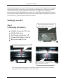
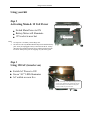
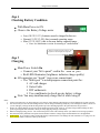
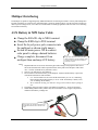
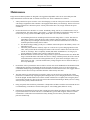
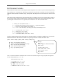
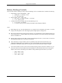
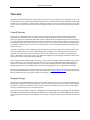
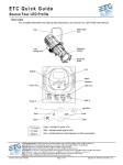
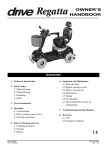
User Manual Model: 201E Perigee Power Solutions Solar Power Kit User Manual Congratulations on your purchase of an alternative power generator kit. This document is designed to be as easy to follow as it is easy to use our kit for your electrical needs. There may be subtle variations between the product and the documentation. For example, we may change the placement of a switch on the dashboard or rename a given label. The functionality will always be the same and the steps provided will persist across any version changes & upgrades we may make to the interface or system. Keep this manual for reference. Setting up your Kit The 201 dash appears like this after unpacking. No power is currently supplied to the kit. This black ribbed component is the 201 14Ah battery pack. Step 1 Connecting the Battery Unlatch & open the 201 case Lift the battery up Verify power switch is “off” Connect the battery to the kit Kit is now ready to use Pulling up the battery pack you’ll see the connector was separated for shipping purposes. Simply connect red to red, black to black and replace the battery into its compartment. The 201 is now connected to its power supply. Note: These images show the legacy SLA 14Ah battery. The battery pack now ships in a tough shrink wrap and houses our new AGM Deep Cycle with a total 15Ah. -2- Perigee Power Solutions Solar Power Kit User Manual Using your Kit Step 2 Activating Main & 12 Volt Power Switch Main Power to ON Battery Meter will illuminate 12V socket is now hot Main Power Switch On illuminates battery meter. 12V socket is hot Notes: 1. See steps 4 & 5 for battery status\charge info. 2. The 201 kit is the only Medium Kit that ships with a modular battery pack. It may be unplugged & easily removed from the kit. Always disconnect any attached electrical device and shut off the kit (both inverter & main power) prior to swapping out your battery pack. Step 3 Using 120 AC (inverter on) Switch AC Power to ON Green “AC” LED illuminates AC outlets are now live The AC power only works when the main power is on and can be checked by the green LED near the rocker. Remember you’re limited to wattage the inverter is rated for your AC devices. -3- Perigee Power Solutions Solar Power Kit User Manual Step 4 Checking Battery Condition With Main Power to ON Observe the Battery Voltage meter o Low (10.5V-11.1V), batteries must be charged before use. o Normal (11.2V-13.4V), this is normal operating range. o Max (13.5V-14.5V), this is the max battery capacity range. Note: See Maintenance section for meaning of “normalization”. “Solar In” LED shows quality of charge. The brighter the LED the higher the charge rate. Step 5 Charging Main Power Switch On o Connect your “kit to panel” cord in the “Solar In” port o Red LED illuminates (brightness indicates charge quality) All connectors are “keyed” (zero cross connections) o The “Multi-port” is a multipurpose connection point for: AC wall charger Gator Cable DIY enthusiasts Use a multimeter to check precise battery voltage Note: You may simultaneously charge the kit while using it! Notes: 1. Always turn main power on when applying a solar charge. Solar charging with main power off will damage the system over time. 2. It is not necessary to have full sun to charge the kit. You can charge even during cloudy days. The recharge rate will be slower but you can still apply a charge and the kit has guards to prevent it discharging back to the panel when the sun goes down. 3. Perigee AC Charge adapters are keyed to use the multi-port instead of the “solar in”. You may charge without turning on main power, bypassing the solar controller, directly & safely applying a charge to the battery. 4. When not charging\using your kit – turn off the main power switch. This will help ensure your batteries last as long as possible. 5. The status bar battery LED has been replaced with a numeric monitor. Voltage ranges documented here are still applicable. 6. WARNINGS: Never attempt to charge without the battery connected as this will damage the solar controller. Never plug a live AC device into the outlets on the kit. It will fry the inverter. -4- Perigee Power Solutions Solar Power Kit User Manual Multiport Interfacing The multiport is capable of supporting many additional functions for all Perigee Products. You may link multiple kits together in parallel (very useful for our wall mount units), connect an auxiliary battery, use the port with a voltmeter to observe precise voltage levels, even connect to a wind turbine or Honda gas generator. This text will cover connecting an external AUX battery . AUX Battery & MPI Gator Cable Clamp the BLACK clip to NEG terminal. Clamp the RED clip to POS terminal. Insert the keyed power pole connector into the multiport as shown (right image). Switch kit main power ON & connect solar panel to charge chained batteries. Charge complete, disconnect from multiport then unclamp AUX battery. Image shows 44Ah AUX battery & MPI cable connected to a 201 kit multiport with a 45W panel also connected to the Solar In (panel not in frame). Notes: 1. Important! Do not reverse\cross connect the gator cable. Doing so will pop the in-line fuse. If this occurs disconnect the cable & open the blister on the positive line. Replace with a STD ATC 7.5A fuse (available at any automotive store) 2. Only use 12V batteries for AUX batteries. 3. Do not connect a dead AUX battery to the multiport. Anytime another battery is put in line with the kit both batteries will normalize. a. I.E. – the kit batteries are at 12.8V and the AUX battery is at 11.9V, connecting them will draw down the kit battery to 11.9V. If the AUX battery is dead (<10V) you will damage the kit battery. b. We recommend checking your batteries voltage with a voltmeter before putting in line. 4. The battery meter will report voltage of all batteries (Kit battery + AUX) as one battery. 5. When adding another battery inline it may also be desirable to use a larger solar panel & maintain a satisfactory recharge rate. Image shows AUX battery MPI cable and the blister that houses the 7.5A STD ATC fuse. -5- Perigee Power Solutions Solar Power Kit User Manual Maintenance Perigee Power Solutions products are designed to be rugged and dependable. There are no serviceable parts that require maintenance aside from what we consider to be basic care. Those conditions are as follows: 1. Always turn the kits power switch to “ON” when charging via solar in. If the power switch is left off when a solar charge is applied the solar controller is not engaged and the battery will not charge. The kit will become damaged if this state is allowed to persist. A short period in this state is ok; simply switch the kit power switch to on. 2. Do not allow batteries to fall below 10.5 Volts. Periodically charge your kit (we recommend once every 8 weeks minimum). The voltage meter is an accurate (+/- 1 digit) representation of the battery charge state. It is not necessary to keep your kit at the Max capacity all the time. 12-13 Volts are sufficient. a. b. c. d. Avoid running the kit for an extended period of time with voltage below 11 Volts. This does not immediately adversely affect the kit but it will eventually reduce the number of cycles that the battery pack may be recharged. If the kits battery state is allowed to drain below 10.9 Volts for a sustained period the warranty will be voided. For detailed voltage reading you may use a voltmeter in the multi-port to check battery status, even when the kit is off. The battery status indicator will rarely report 14.5 volts. Even if you are charging and do see this value, when you take the kit off charge the batteries will normalize and the meter will settle down into the 12 Volt range. This is completely normal (and called “normalization”). As long as you operate within the “normal” range your kit is charged as expected. Remember that the inverter has a low voltage cut off (see specs toward end of this doc). When that range is reached the alarm will sound. Once the low voltage condition persists, the inverter will cut off and the batteries will need to be charged before the AC power can be used again. There is no alarm for the 12V port – you must monitor battery voltage using the meter to ensure the battery is not overly discharged. 3. Do not allow water to penetrate the interior of the kit. A little water on the dashboard will not harm the kit but submerging the electronics will damage the inverter beyond our capacity to service it. Do not under any circumstance attempt to plug something into the kit and turn it on if the kit has become water logged! This kit generates electric current. Always remember that water and electricity don’t mix! 4. The solar panel(s) are sealed and may be exposed to water, rain, & snow but to extend the life of these products we recommend only exposing the panels during the time you are charging the batteries or running the kit in daylight. Periodic durations in variable weather conditions are acceptable, but leaving the panels exposed to the elements for days\weeks\years will result in natural material fatigue. When your case is being stored, store the panel(s) inside\with the case. 5. Keep your panels clean for the best performance. A damp cloth is all that is needed to remove dust & dirt. We recommend using a non-abrasive cloth for either glass or A-Si (folding panel) material. Air dry. 6. If batteries become damaged, do not use them. Normal use will not harm your batteries and we include a fuse to protect them from over current. The fuse is a standard auto type fuse that if tripped, will have a broken element that is visible when removed from the battery housing. Do not remove your battery from the protective shrink wrap. -6- Perigee Power Solutions Solar Power Kit User Manual Kit Duration Formula Battery duration formula based on total Amp hour and the Amp draw rate of a device you are interested in powering. Note: Puekerts Law is normally 90%. While this provides better formula results we modify to account for additional unknown variables such as environment, usage, & temperature. This has proven to be more accurate in all of our field tests. This simple formula calculates battery duration based on device amp draw & inverter at no load. We then account for the loss of power that is inherent with an inverter at full load. The example below shows an LED lamp using .068A (per hour) plus the 201 kit inverter .21A (per hour) for a total draw of .278. Here's the break-down: a. b. c. d. Battery Ah * 85% (Puekerts Law) = x x / total amp draw average of device & inverter = y (gross time duration) y * 85% (avg. inverter efficiency @ full load) = xy xy * 0.6 = z (Est. run-time @ 40% deep cycle battery Safe Discharge Level) a. b. c. d. x = 12.75Ah (15Ah * .85 = 12.75) y = 45.53 (12.75 / .28 = 45.53) xy = 38.70 (45.53 * .85 = 38.70) z = 23.22 hours to SDL (38.70 * 60% = 23.22) The above formula assumes a flat constant draw rate without variation. To calculate a variable device we need to do additional math. Here is the formula to calculate average amp per hour that considers max & min draw: (Imax * Tactive / 3600) + (Imin * (3600 - Tactive) / 3600) = Iavg Imax = max amp draw from battery Tactive = time in seconds drawing max amps Imin = min amp draw from battery 3600 = num of seconds on one hour Iavg = avg amp draw per hour Example: Imax = 2A Tactive = approx. 10min (600 seconds), Imin = 0.65A (2 * 600) / 3600 = 0.33A (0.65 * 3000) / 3600 = 0.54A 0.33A + 0.54A = 0.87A Iavg = 0.87A Now we can take the duration formula and derive the run-time estimate using the average amp hour value plus the inverter consumption (Iavg = .87 + .21) Total Amp Draw Avg = 1.08 x = 12.75Ah (15Ah * .85 = 12.75) y = 11.81 (12.75 /1 .08 = 11.81) xy = 10.03 (11.81 * .85 =10.03) z = 6.02 hours to SDL (10.03 * 60% = 6..02) -7- Perigee Power Solutions Solar Power Kit User Manual Battery Recharge Formula Derive the time it takes to recharge a battery from safe discharge level to a normalized state. Evaluate the following: 1. 2. 3. Panel Wattage / Panel Voltage Rating = Amps a. (45W panel / 17.3V rating = 2.6A) b. 2.6 = panel amp rating Battery Amp hr / Amp = Time + 10% a. (42 / 2.60) * 1.10 battery variable = 17.76 hours b. 17.76 = gross avg. time Calculate for deep cycle recharge time from Safe Discharge Level a. (17.76 * 60% = 10.66 hours) b. 10.7 hours is the avg. time to recharge from SDL in ideal charging conditions. Notes: Panel ratings may vary. You may substitute the 17.3V rating for 15V to normalize your results. 17.3V is the rating for the 45W panels we sell. Increasing the panel wattage improves recharge time. Most inverter manufacturers provide inverter efficiency at 1/3 and full load. You may substitute the 85% avg we use for this (step “c”) with the MFG rating. We provide this data on a kit basis on the specification page when it is available to us. During recharge a battery at 60% SDL is actually 40% discharged, therefore (.4) is the value we need to use when figuring recharge time for non-deep cycle batteries. These formulas are average estimates. There are potentially many other factors that can affect your calculations including battery age (number of cycles it’s been through). Over time this will affect the performance of the battery and as such we can expect the time derived from this formula to expand. To use these formulas you have to know how to find the Amperage, Watts, and Volts of whatever it is you want to run. There are several online conversion calculators. Look at the back of the device (or the power adapter). There will be a label that gives the INPUT Voltage and having this info allows you to find: o o o Amps = Watts \ Volts Watts = Volts * Amps Volts = Watts \ Amps -8- Perigee Power Solutions Solar Power Kit User Manual Warranty Perigee Power Solutions shall provide quality products at fair prices. We personally test each component we use in our kits and maintain a process based upon fundamentals that verify we build our products right and that we built the right product. If you ever encounter a problem with our products, let us know as soon as possible. We promise to work with you on a case-by-case basis to resolve issues if they should arise. Please note we do not honor any third party warranty claims. Limited Warranty Returns are accepted within 14 days of purchase for a refund. Perigee Power Solutions warrants kits for 90 days against defects in workmanship for our entire product line (fully assembled kits) and all devices manufactured expressly by Perigee Power Solutions. Individual 3rd party components not assembled by Perigee Power Solutions are covered by our limited warranty through those respective manufacturer(s). Our warranty provides coverage for defects in manufacturing only and expressly excludes coverage for excessive wear and tear and/or physical/accidental abuse, loss and theft. Improper repair or warranty service performed by someone other than Perigee Power Solutions shall void this warranty. Customer is responsible for return shipping charges. Returns are processed by Perigee Power Solutions after receipt verification. Returns must arrive in the original shipping box in condition "new" with all original components & documents for refund consideration. Customer agrees to use only reputable carriers capable of providing proof of delivery and insurance for the entire value of the shipment and agrees to bear all shipping and insurance charges and all risk of loss for the return product during shipment. If any component of the returned product is missing, or if the product is no longer sellable as condition "new" Perigee Power Solutions may, in its discretion, reject the entire return or choose to impose additional charges against the customer for replacement of missing component(s). Perigee Power Solutions shall not refund original shipping or handling charges and a 10% restocking fee derived from the original purchase price is applicable to all refunds. Please do not attempt to process returns from the store you purchased your kit. Ship to: Perigee Power Solutions PO Box 906 Hampstead MD 21074. Send any return related questions to [email protected]. Returns for purchases made on Amazon.com may be processed via their return request system. Shipping Damage Any damages incurred during shipping must be reported within 24 hours of receipt. Be sure to inspect all packages for damage before signing for the package. If damage is visible, reject the shipment, be sure the driver notes the damage and contact Perigee Power Solutions as soon as possible. Perigee Power Solutions will file a claim with the shipper and ship a replacement upon return of the damaged item. Perigee Power Solutions DISCLAIMS ANY LIABILITY FOR CONSEQUENTIAL OR INCIDENTAL DAMAGES FOR BREACH OF WRITTEN OR IMPLIED WARRANTY OF THIS ITEM, INCLUDING MERCHANTABILITY OR FITNESS FOR A PARTICULAR PURPOSE. Our warranty is valid only at Perigee Power Solutions & within the U.S.A. -9- Perigee Power Solutions Solar Power Kit User Manual Specs: 1. Pelican Case 1400 • External Dimensions: 13.37" L x 11.62" W x 6" D • Weight < 20lbs (fully loaded with the following components) 2. Power Ports • Solar panel input color coded & keyed port • Auxiliary input color coded & keyed port • 12 volt DC Power out (marine cigarette lighter plug) • 120 volt AC power out (2ea US 60Hz) 3. Lower Case Compartment • Battery space - Two (2) Sealed Rechargeable 12Volt 7.5Ah (15Ah\180Wh) • Electronics kit • Power Controller • Regulations point: 14.5 Volts • Low voltage Disconnect: 11.1V Volts • Low voltage Reconnect: 12.5 Volts • Microcontroller digital accuracy • Electronic protections: Short circuit, over current-solar & load • High Voltage Load Limit Protection • Inverter (PSW, 180 watts continuous, 360 watt overload protection) • No load drain .38 Amps DC • Full load efficiency: 90% 4. Dashboard • Foldable solar panel & cable storage space (may remove foam in lid for additional space) • Universal Main power On\Off Switch • Universal Inverter On\Off Switch • LED Battery Status (now displayed via numeric read-out) 5. Notes • AC charge adapter support via multi-port (for battery maintenance off the grid) • Auxiliary parallel battery support via multi-port • Trailer style 2 pin connectors are extremely “tight” when new. Gently working the two ends together\apart during normal use will “break in” the part. • 12V adapters (i.e. USB, etc.) are available at your favorite automotive\marine shop. • Extension cables and splitters for solar panel(s) use 2-pin trailer style plug from any manufacturer. - 10 - Perigee Power Solutions Solar Power Kit User Manual QC Checklist Item Solar Panel Cables (Continuity) LEDs 12VDC port 110VAC port 110VAC Load Test Accessory. (USB, AC Charger, AUX Jumper, et al) Battery (12VDC) AUX Multi-port Result □ □ □ □ □ □ □ □ □ Notes Date Tested: __________________ Initial: __________________ Contact Info Sales & Support Email: [email protected] Phone: 443-375-3765 More Information Look for our videos on YouTube and news on Facebook. Links to both are available on our website. Perigee Power Solutions markets their kits under provisional patent US61\384200. Thank you for your interest in Perigee Power Solutions! - 11 -