1
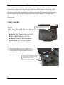
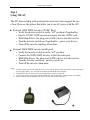
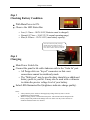
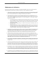
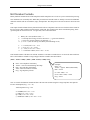
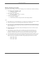
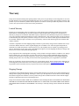
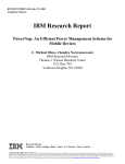
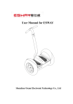
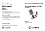
User Manual
Model: 007
Perigee Power Solutions
Solar Power Kit User Manual
Congratulations on your purchase of an alternative power charger kit! This document is designed
to be as easy to follow as it is easy to use our kit for your electrical needs. There may be subtle
variations between the product and the documentation. For example, we may change the
placement of a switch on the dashboard or rename a given label. The functionality will always be
the same and the steps provided will persist across any version changes we may make to the
interface. Refer back to this manual for advice on caring for your kit (battery maintenance) and
general usage.
Using your Kit
Step 1
Activating Main & 12 Volt Power
Main Power Switch On activates the 12V
status LED and powers the 12VDC port.
Insert Buss fuse & turn cap to fit.
Switch Main Power to ON.
Battery status LED illuminates.
Uncap & use 12VDC socket.
Notes:
1. If the status bar indicates “low” see the Steps 3 & 4.
2. The 201 modular battery pack may be connected to the
007 via the multi-port using our “Medium AUX battery
MPI cable” (each sold separately).
Image shows the 007 with panel connected &
charging kit while simultaneously powering
an MP3 player via the 12V port.
-2-
Perigee Power Solutions
Solar Power Kit User Manual
Step 2
Using 110 AC
The 007 does not ship with an internal inverter but it does support the use
of one. Here are the options that allow you to use AC power with the 007.
External 140W MSW inverter (12VDC Port)
o Verify the inverter switch is in the “off” position (if applicable).
o Insert a 12VDC 140W inverter accessory into the 12VDC port.
o With Main Power On, plug your (140W) device into the inverter.
o Turn the inverter switch on (if applicable) - power your device.
o Turn off the inverter (unplug) when done.
External 200W MSW inverter (multi-port)
o Verify the inverter switch is in the “off” position.
o Connect the 200W MSW inverter to the kits multi-port.
o With Main Power On, plug your (200W) device into the inverter.
o Turn the inverter switch on - power your device.
o Turn off the inverter when done.
Notes:
1. If using a 12VDC port inverter model, there may \ may not be an external on\off switch on the inverter itself. Most
are just “plug in and it’s on”; it depends on the model on hand at the time of shipping.
2. Turning the inverter off when not in use is recommended as a battery saving tactic.
3. Always verify the use of electronics with the manufacturer when connecting to a modified sine wave (MSW).
4. We also offer an external 180W pure sine inverter for use with sensitive electronics.
-3-
Perigee Power Solutions
Solar Power Kit User Manual
Step 3
Checking Battery Condition
With Main Power to ON.
Observe the LED Status Bar.
o Low (1-3 bars = 10.0V-10.5V, Batteries must be charged)
o Normal (4-7 bars = 10.6V-12.5V, normal operating range)
o Max (8-10 bars = 12.6V-14.5V, max battery capacity)
“Solar In” LED shows quality of charge
(brighter the LED the higher the charge
rate). The black \ red connector on the panel
to kit cable is called an Anderson connector.
Step 4
Charging
Main Power Switch On.
Connect the panel to kit cable Anderson side to the “Solar In” port.
o All Perigee kits use “keyed” connectors so that cross
connections cannot be mistakenly made.
o The “Multi-port” may be used to daisy chain kits or additional
battery packs to your kit. It may also be used with a voltmeter
to obtain the precise voltage level of your battery.
Solar LED illuminates Red (brightness indicates charge quality).
Notes:
1. Always turn the power switch on when applying a charge from any source. See the
maintenance section for details.
2. When not using your kit, switch off the main power. This will increase the lifespan of the
battery and prevent potential cell damage from over drain. You may remove the fuse to
facilitate a hard disconnect if so desired.
-4-
Perigee Power Solutions
Solar Power Kit User Manual
Multiport Interfacing
The multiport is capable of supporting many additional functions for all Perigee Products. You may link multiple kits
together in parallel (very useful for our wall mount units), connect an auxiliary battery, use the port with a voltmeter to
observe precise voltage levels, or connect to a compatible wind turbine. This text will cover connecting an AUX
battery.
AUX Battery & MPI Gator Cable
Clamp the BLACK clip to NEG terminal.
Clamp the RED clip to POS terminal.
Insert the keyed power pole connector into
the multiport as shown (right image).
Switch kit main power ON & connect
solar panel to charge chained batteries.
When charged to desired level, disconnect
MPI from multiport. Unclamp cable from
AUX battery.
Image shows 44Ah AUX battery & MPI
cable connected to a 201 kit multiport with a
45W panel also connected to the Solar In
(panel not in frame).
Notes:
1. Important! Do not reverse\cross connect the gator cable. Doing so will pop the inline fuse. If
this occurs disconnect the cable & open the blister on the positive line. Replace with a STD
ATC 7.5A fuse (available at any automotive store)
2. Do not connect a dead AUX battery to the multiport. Anytime another battery is put in line
with the kit both batteries will normalize. I.E. – the kit batteries are at 12.8V and the AUX
battery is at 11.9V, putting them in line will draw down the kit battery to 11.9V. If the AUX
battery is dead (<10V) you may damage your kits battery. We recommend checking your
batteries voltage with a voltmeter before putting in line.
3. The status bar on the kit reports voltage of all batteries (Kit battery + AUX) as one battery.
Image shows AUX battery MPI cable and
the blister that houses the 7.5A STD ATC
fuse.
-5-
Perigee Power Solutions
Solar Power Kit User Manual
Maintenance & Advisories
Perigee Power Solutions products are designed to be rugged and dependable. There are no serviceable parts that
require maintenance aside from what we consider to be basic care. Those conditions are as follows:
1.
Always turn the kits power switch to “ON” when charging. If this switch is left off when a charge is applied,
from any source, the batteries will not charge and the kit may become damaged if this state is allowed to
persist. A short period in this state is ok; simply switch the kit power switch to on.
2.
Do not allow batteries to fall below 10 volts. Periodically charge your kit (we recommend once every 8
weeks). The power status bar is an accurate representation of the battery charge condition. It is not necessary
to keep your kit at Full\Max capacity all the time. 12-13 volts are sufficient, i.e. - any bar in the “normal”
range on the power meter.
a.
b.
c.
Avoid running the kit for an extended period of time with the indicator in the “Low” position. This
does not immediately adversely affect the kit but it will eventually reduce the number of cycles that
the battery pack may be recharged. If the kits battery state is allowed to drain below two bars the
warranty may be voided.
For detailed voltage reading you may use a voltmeter in the multi-port to check battery status, even
when the kit is off.
The battery status indicator will rarely be completely illuminated, as this is 14.5 volts. Even if you
are charging and do see this completely illuminated when you take the kit off charge, the batteries
will normalize and the meter will settle down a couple bars. This is completely normal. As long as
you operate within the “normal” range your kit is charged as expected.
3.
Do not allow water to penetrate the interior of the kit. A little water on the dashboard will not harm the kit but
submerging the electronics may damage the inverter beyond our capacity to service it. Do not under any
circumstance attempt to plug something into the kits inverter and turn it on if the kit has become water
logged! This kit generates electric current. Always remember that water and electricity don’t mix!
4.
The solar panel(s) are sealed and may be exposed to water, rain, & snow but to extend the life of these
products we recommend only exposing the panels during the time you are charging the batteries or running
the kit in daylight. Periodic durations in variable weather conditions are acceptable, but leaving the a-Si
folding panels exposed to the elements for extended periods (weeks\years) will result in natural material
fatigue. When your case is being stored, store the panel(s) inside\with the case.
5.
Keep your panels clean for the best performance. A damp cloth is all that is needed to remove dust & dirt. We
recommend using a non-abrasive cloth that will not scratch the glass or a-Si (folding panel) material when
cleaning. Air dry.
6.
If batteries become damaged, do not use them. Normal use will not harm your batteries and we include a fuse
to protect them from over current. The fuse is a standard auto type fuse that if tripped, will have a broken
element that is visible when removed from the battery housing (or the dashboard as is the case with the 007).
Do not remove your battery from the protective (and sealed) housing provided by Perigee Power Solutions.
7.
We manufacture a “Gator” cable that is designed to plug into the multi-port and allow you to connect probes
from a voltmeter to derive a detailed voltage reading on kits that just have a battery status bar. Take care that
you don’t touch the two clips together when plugged into the multi-port as this will blow the inline 7.5A ATC
fuse. If this occurs simply remove the fuse cover on the gator cable and replace with a 7.5A or 10A ATC fuse.
8.
We manufacture accessories called Multi-port Interface switches. These vary in function from model rocket
ignition to wind turbine interfaces with our kits. With regards to usage see the product details on the website
-6-
Perigee Power Solutions
Solar Power Kit User Manual
Kit Duration Formula
Battery duration formula based on total Amp hour and the Amp draw rate of a device you are interested in powering.
Note: Puekerts Law is normally 90%. While this provides better formula results we modify to account for additional
unknown variables such as environment, usage, & temperature. This has proven to be more accurate in all of our field
tests.
This simple formula calculates battery duration based on device amp draw & inverter at no load. We then account for
the loss of power that is inherent with an inverter at full load. The example below shows an LED lamp using .068A
(per hour) plus the 201 kit inverter at .21A (per hour). Here's the break-down:
a.
b.
c.
d.
Battery Ah * 85% (Puekerts Law) = x
x / total amp draw average of device & inverter = y (gross time duration)
y * 85% (avg. inverter efficiency @ full load) = xy
xy * 0.4 = z (Est. run-time @ 60% battery Safe Discharge Level)
a.
b.
c.
d.
x = 11.9Ah (14Ah * .85 = 11.9)
y = 41.0 (11.9 / .29 = 41.03)
xy = 34.87 (41.03 * .85 = 34.87)
z = 13.95 hours to SDL (34.87 * 40% = 13.95)
This formula assumes a flat draw rate without variation. To calculate a variable device we need to do more math first.
Here is the formula to calculate average amp per hour that considers max & min draw:
(Imax * Tactive / 3600) + (Imin * (3600 - Tactive) / 3600) = Iavg
Imax = max amp draw from battery
Tactive = time in seconds drawing max amps
Imin = min amp draw from battery
3600 = num of seconds on one hour
Iavg = avg amp draw per hour
Example:
Imax = 2A
Tactive = approx. 10min (600seconds),
Imin = 0.65A
(2 * 600 / 3600) = .33
(0.65 * 3000 / 3600) = 0.54A
Iavg = 0.87A
Now we can take the duration formula and derive the run-time estimate using the average amp hour value plus the
inverter consumption (Iavg = .87 + .21)
Total Amp Draw Avg = 1.08
x = 11.9Ah (14Ah * .85 = 11.9)
y = 11.0 (11.9 /1 .08 = 11.01)
xy = 9.36 (11.01 * .85 =9.36)
z = 3.74 hours to SDL (9.36 * 40% = 3.74)
-7-
Perigee Power Solutions
Solar Power Kit User Manual
Battery Recharge Formula
Derive the time it takes to recharge a battery from safe discharge level to a normalized state. Evaluate the following:
1.
2.
3.
Panel Wattage / Panel Voltage Rating = Amps
a. (45W panel / 17.3V rating = 2.6A)
b. 2.6 = panel amp rating
Battery Amp hr / Amp = Time + 10%
a. (40 / 2.60) + 10% battery variable = 16.92 hours
b. 16.9 = gross avg. time
Calculate for 60% Safe Discharge Level
a. (16.9 * 40% = 6.76 hours)
b. 6.7 hours is the avg. time to recharge from SDL in ideal charging conditions.
Notes:
Panel ratings may vary. You may substitute the 17.3V rating for 15V to normalize your results. 17.3V is the
rating for the 45W panels we sell. Increasing the panel wattage improves recharge time.
Most inverter manufacturers provide inverter efficiency at 1/3 and full load. You may substitute the 85% avg
we use for this (step “c”) with the MFG rating. We provide this data on a kit basis on the specification page
when it is available to us.
During recharge a battery at 60% SDL is actually 40% discharged, this is the value we need to use when
figuring recharge time.
These formulas are average estimates. There are potentially many other factors that can affect your
calculations including battery age (number of cycles it’s been through). Over time this will affect the
performance of the battery and as such we can expect the time derived from this formula to expand.
To use these formulas you have to know how to find the Amperage, Watts, and Volts of whatever it is you
want to run. There are several online conversion calculators. Look at the back of the device (or the power
adapter). There will be a label that gives the INPUT Voltage and having this info allows you to find:
o
o
o
Amps = Watts \ Volts
Watts = Volts * Amps
Volts = Watts \ Amps
-8-
Perigee Power Solutions
Solar Power Kit User Manual
Warranty
Perigee Power Solutions shall provide quality products at fair prices. We personally test each component we use in our
kits and maintain a process based upon fundamentals that verify we build our products right and that we built the right
product. If you ever encounter a problem with our products, let us know as soon as possible. We promise to work with
you on a case-by-case basis to resolve issues if they should arise.
Limited Warranty
Returns are accepted within 14 days of purchase for a refund. Perigee Power Solutions warrants kits for 90 days
against defects in workmanship for our entire product line (fully assembled kits) and all devices manufactured
expressly by Perigee Power Solutions. Individual 3rd party components not assembled by Perigee Power Solutions are
covered by our limited warranty through those respective manufacturer(s). Our warranty provides coverage for defects
in manufacturing only and expressly excludes coverage for excessive wear and tear and/or physical/accidental abuse,
loss and theft. Improper repair or warranty service performed by someone other than Perigee Power Solutions shall
void this warranty.
Customer is responsible for return shipping charges. Returns are processed by Perigee Power Solutions after receipt
verification. Returns must arrive in the original shipping box in condition "new" with all original components &
documents for refund consideration. Customer agrees to use only reputable carriers capable of providing proof of
delivery and insurance for the entire value of the shipment and agrees to bear all shipping and insurance charges and
all risk of loss for the return product during shipment.
If any component of the returned product is missing, or if the product is no longer sellable as condition "new" Perigee
Power Solutions may, in its discretion, reject the entire return or choose to impose additional charges against the
customer for replacement of missing component(s). Perigee Power Solutions shall not refund original shipping or
handling charges and a 10% restocking fee derived from the original purchase price is applicable to all refunds.
Please do not attempt to process returns from the store you purchased your kit. Ship to: Perigee Power Solutions 351
Green Ridge Road, New Oxford PA 17350. Send any return related questions to [email protected]. Returns
for purchases made on Amazon.com may be processed via their return request system.
Shipping Damage
Any damages incurred during shipping must be reported within 24 hours of receipt. Be sure to inspect all packages for
damage before signing for the package. If damage is visible, reject the shipment, be sure the driver notes the damage
and contact Perigee Power Solutions as soon as possible. Perigee Power Solutions will file a claim with the shipper
and ship a replacement upon return of the damaged item.
Perigee Power Solutions DISCLAIMS ANY LIABILITY FOR CONSEQUENTIAL OR INCIDENTAL DAMAGES
FOR BREACH OF WRITTEN OR IMPLIED WARRANTY OF THIS ITEM, INCLUDING MERCHANTABILITY
OR FITNESS FOR A PARTICULAR PURPOSE. Our warranty is valid only at Perigee Power Solutions & within the
U.S.A.
-9-
Perigee Power Solutions
Solar Power Kit User Manual
Specs:
1. Pelican Case 1150
• External Dimensions: 9.25"L x 7.56"W x 4.38"H
• Weight < 7lbs (fully loaded with the following components)
2. Power Ports
• Solar panel input color coded & keyed port
• Auxiliary input color coded & keyed port
• 12 volt DC Power out (standard cigarette lighter plug)
3. Lower Case Compartment
• Battery space - One Sealed Rechargeable 12Volt 7Ah
• Electronics kit
• Power Controller
• Regulations point: 14.5 Volts
• Low voltage Disconnect: 11.1V Volts
• Low voltage Reconnect: 12.5 Volts
• Microcontroller digital accuracy
• Electronic protections: Short circuit, over current-solar and load
• Limits high voltage to protect battery
4. Dashboard
• Internal DC port
• Main power On/Off Switch
• LED Indicators (reports battery state, solar charging state and 12 volt output)
• Uniquely configured and color coded plug\port for use with our:
• AC charge adapter (for easy in home battery maintenance straight off the grid)
• Daisy chain (connects multiple kits in parallel and recharge batteries from one source)
• Probe this port using a voltmeter to check specific voltage level
- 10 -
Perigee Power Solutions
Solar Power Kit User Manual
Notes:
- 11 -
Perigee Power Solutions
Solar Power Kit User Manual
QC Checklist
Item
Solar Panel
Cables (Continuity)
LEDs
12VDC port
Load Test (60W w\ Ext Inverter)
Accessory. (USB, AC Charger, AUX Jumper, et al)
Battery (12VDC)
AUX Multi-port
Result
□
□
□
□
□
□
□
□
Notes
Date Tested: __________________
Initial: __________________
Contact Info
Email:
[email protected] or [email protected]
Phone:
443-375-3765 Sales & Support
More Information:
Look for our videos on YouTube and news on Facebook. Links to both are available on our website.
Accessories
For some additional components to augment the kits functionality visit our Accessory page.
1.
2.
3.
4.
5.
6.
7.
Panel Expansions (increases the kits solar recharge rate)
Dual\Quad Delphi Daisy Chain Wiring Harness (supports additional panels for models 007-301)
AC Wall Adapter (charge the from grid, 14Ah max &28Ah and up)
Modular Battery Pack (201 swap use. 301/101/007 use via multi-port)
Panel Extension Cable (12’ for models 301-007. 30’ ext. for model 401)
12V DC to 140W adapter (…for the 007)
12V USB Adapter (…for charging your USB devices)
Perigee Power Solutions markets their kits under provisional patent US61\384200.
Thank you for your interest in Perigee Power Solutions!
- 12 -