1
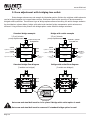
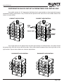
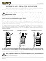
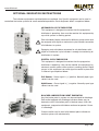
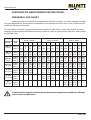
L.D. PROGRESSIVE SYSTEM
DISTRIBUTORS
INTRODUCTION AND USER MANUAL
VERSION 2.00
www.allfett.net
INTRODUCTION
All industrial machinery, equipments and vehicles are working under abrasive operating conditions.
The wear between frictional parts become the most highest level at these conditions. Machinery expose bad
weather, dust, dirt, rain, snow and heavy weight in most cases. Consequently unwanted breakdowns occur
and by that way productivity loss is inevitable.
Using automatic lubrication system only increase your profitability. ALLFETT completely take over
the work load spend on lubrication with a system which is bringing togather a pump, control unit, distributors,
tubes and couplings. Lubrication work is done by ALLFETT centralized lubrication systems in efficient time
of machinery or vehicle which is while operating.
Lubrication is important for all frictional parts but using correct lubrication system and method only
protect parts from wearing for a long time. Feeding lubrication points with correct dosage of lubricant at
certain intervals while machinery is operating, provides lubricant film in place longer between parts. By
ALLFETT lubrication systems life time of parts on your machinery and vehicles will be increased.
ABOUT MANUFACTURER
With over 25 years experience of manufacturing Centralized Lubrication Systems ALLFETT is able
to provide a wide professional approach to select the correct Centralized Lubrication System for industry and
heavy machinery.
A highly accurate manufacturing process is involved in producing Centralized Lubrication Systems
in order that systems meet the very tight quality procedures and state of the art processes are employed.
ALLFETT is among the few companies whose products meet the exact technical and quality standards for a
correct central lubrication. We present our high quality and advanced product design concept to our worldwide
costumers through our strong brand.
ALLFETT creates new opportunities and innovative solutions. As a result of the satisfaction of our
customers with our good quality lubrication systems we are continuing in growing in the local and international
market and became one of the successful companies in the field.
WARNINGS
Symbols and words shown below are meant to warn a particular risk to persons, material
assets, or the environment. Please carefuly read this manual before installing. Failure to follow the
instructions and safety precautions in this manual could result in serious injury or property damage.
Caution
Prohobition
PAGE
1
Notice
Electricity
www.allfett.net
CONTENTS
INTRODUCTION
PAGE 1
CONTENTS
PAGE 2
PRODUCT DESCRIPTION
PAGE 3
MODULAR COMPONENTS & PRODUCT DIMENSIONS
PAGE 4
PRODUCT COMPONENTS
PAGE 5 - 6
FUNCTIONAL DESCRIPTION
PAGE 7
DOSAGE OPTIONS
PAGE 8 - 9 - 10
OUTLET ALTERNATIVE SAMPLES
PAGE 11
INSTALLATION INSTRUCTIONS
PAGE 12
OPTIONAL INDICATOR INSTRUCTIONS
PAGE 13
RULES TO COMPLY WHILE USING AND WARRANTY CONDITIONS
PAGE 14 - 15
DISTRIBUTOR MAINTENANCE
PAGE 16 - 17 - 18
ORDER INFORMATION
PAGE 19
WARRANTY
PAGE 20
WARRANTY CONDITIONS
PAGE 21
Page
2
www.allfett.net
PRODUCT DESCRIPTION
Pilot controlled progressive L.D. distributors are designed to be used with ALLFETT central lubrication
systems. The grease flow produced by the central lubrication pump will be delivered by these valves to the
lubrication points in specific doses. Lubrication is done at any point in needed pressure (up to 400 bars).
Progressive L.D. distributor can be connected to directly pump element and also another progressive
distributor outlet to meet exact dosage amount. Modular design of distributor block allows to feed all lubrication
points in system with different specific dosages.
The control of lubrication system is operating can be done either by electronic sensor on distributor
or visual indicator. If electronic system is used, the error is show by the control card included in the system.
Progressive L.D. distributor blocks divides the lubricat coming from pump in different or same
amount of dosages. Necessary lubrication point numbers can be feeded with exact amount of grease dosage.
Distance between lubrication points and distributor can be 10 meters long. Steel, poliamid or high
pressure tube types can be used with their recomended couplings.
GENERAL SPECIFICATIONS
Max. working pressure
: 400 bar.
Min. pressure to operate
: 7,5 bar.
Grease types
: NLGI - 00, 0, 1, 2, 3
Outlet thread
: M10x1
Mounting screws
: M6 allen screws
Outlet variations
: From 2 outlet to 18 outlet can be
ctreated in single distributor block.
Piston dosage volumes
: Ø4mm
Ø5mm
Ø6mm
Ø7mm
Ø8mm
Operating temperatures
: -25°C +80°C
Modular elements
: At least 3 middle element,
at most 9 middle elements can be used
single distributor block
piston
piston
piston
piston
piston
-
0.060cc
0.088cc
0.141cc
0.192cc
0.250cc
/
/
/
/
/
stroke
stroke
stroke
stroke
stroke
Distance between lubrication points and distributor can be 5 meters. Between 5 and
10 meters distances a check-valve should be used at outlet. Do not use lines longer
than 10 meters.
Page
3
www.allfett.net
MODULAR COMPONENTS
Progressive L.D. distributor block is created by
combining 3 different elements. Block is named by middle
lement quantity its own. (for example 3/6 block means
3 middle element and 6 outlet ports)
Start element
Piston
Start element allows grease inlet to distributor
block.
Middle element supply outlet ports and pilot
controling system.
Middle element
End element allows the pilot system to be operated
continously.
Outlet coupling
End element
GENERAL DIMENSIONS
Technical drawing below represents the distributor block that has 3 middle elements and 6 outlets.
Each middle element increasing adds 15mm to total hight dimension.
60mm
3/6 distributor block
50
19.7 19.7 19.7 19.7 19.7
24
98
Page
4
www.allfett.net
PRODUCT COMPONENTS - (SCHEMA)
Technical drawing below represent distributor block components which is standard and optional.
Each component showed by numbers and next page shows explanation of each number.
1
20
2
21
3
22
23
4
5
6
24
25
7
8
26
27
9
10
28
29
11
12
13
30
31
14
32
15
16
17
18
19
Page
5
33
www.allfett.net
PRODUCT COMPONENTS - (DESCRIPTION)
Product component decriptions are shown below. Each component showed by numbers in page 5.
explained below.
1.
2.
3.
4.
5.
6.
7.
8.
9.
10.
Assembly screws
Ø13x1,5 O-Ring
Bridge body
Bridge coupling (with outlet)
Bridge coupling (blind)
Bridge washer
Blinding screw
Piston screw
Ø14x1,5 O-Ring
Ø3x1,5 O-Ring
Standard component
Standard component
Optional component
Optional component
Optional component
Optional component
Optional component
Standard component
Standard component
Standard component
11.
12.
13.
14.
15.
16.
17.
18.
19.
20.
Straight coupling
Sensore body
Sensore coupling
Ø3xØ7x3 nutring
Indicator coupling
Indicator piston
Indicator coupling screw
Sensore
End element
Start element
Optional component
Optional component
Optional component
Optional component
Optional component
Optional component
Standard component
Standard component
Optional component
Optional component
21.
22.
23.
24.
25.
26.
27.
28.
29.
30.
31.
Ø8x1,5 O-RingMiddle section
0.050cc
Piston Ø4
Middle section 0.078cc
Piston Ø5
Middle section 0.113cc
Piston Ø6
Middle section 0.154cc
Piston Ø7
Middle section 0.201cc
Standard component
Optional component
Optional component
Optional component
Optional component
Optional component
Optional component
Optional component
Optional component
Optional component
31. Piston Ø8
32. Ø4 Steel ball
33. M5 Setscrew
Optional component
Standard component
Standard component
Page
6
www.allfett.net
FUNCTIONAL DESCRIPTION
Along with grease pump in system starts to operate ;
Lubricant sended from pump gives movement to pistons in pilot control section of distirbutor block.
Sequential movement of pistons is continue during pump operates. Pistons are moving in order while pressurized
lubricant coming. When a piston moves to complatelly one side the dosage amount of piston feeds lubrication
point. Each piston feeds connected lubrication points untill pump stops.
Pilot control section
Outlet section
1
2
3
Progressive distributor is connected directly to pump outlet. When necessary, a progressive distributor
can also be connected to other distributor outlet for dosing purposes. Modular design of distributor block
allows to answer any specific dosage needs.
Pilot control of distributor stops to operate and not send any grease if any lubrication point is
blocked. Optional indicator equipments can monitor this blockage. Digital or mechanical indicator options
allows you to warn any blockage in lubrication system. Alarm signal can be created if digital indicator and
electronic control system are used.
Lubrication point indicator option allows you to monitor which lubrication point is blocked. Alarm
signal can be created for blockage with using pressure and electronic control systems. When lubrication point
indicator is used, distributor block still operates if there is a blockage.
Unouthorized modifications to the units and the use of unouthorized spare parts and
aids prohobited also disqualify the warranty.
Page
7
www.allfett.net
DISTRIBUTOR BLOCK DOSAGE OPTIONS
Progressive distributor blocks divides the lubricat coming from pump in different or same amount
of dosage. Necessary lubrication point numbers can be feeded with exact amount of grease dosage.
Description below explain different type of dosage adjustment methods.
1. Dose adjustment with piston sizes.
Progressive distributors has 3 different size of pistons. These pistons are Ø4mm (0,050cc stroke),
Ø5mm (0,078cc stroke) and Ø6mm (0,113cc stroke) diameter sizes. Dosages can be calculated by dividing
stroke volumes with each other. For example, Ø6mm piston volume is equal to 2,26x of 5mm piston (0,113
/ 0,050 = 2,26). Each outlet volume of distributor depens on the pump displacement.
2,5 cm³/minute
pump displacement
14,62 X = 2,5 cm³
X=0,259 cm³
0.251cc
4,04 X
0,686 cm³/ minute
0.251cc
4,04 X
0,686 cm³/ minute
2,27 X
0,385 cm³/ minute
0.141cc
2,27 X
0,385 cm³/ minute
0.141cc
X
0,170 cm³/ minute
0.062cc
X
0,170 cm³/ minute
0.098cc
0.192cc
0.062cc
Ø8
Ø7
Ø6
Ø5
Ø4
2. Dose adjustment with blinding an outlet.
Piston dosage volumes may not enough for lubrication points. Single or multiple outlets can be
blinded to increase outlet volume of a middle element for twice of its amount. Distributor block outlet
quantity wil be decreased equal to blinded outlets. As described on schema below, outlets of distributor block
with 3 middle elements and 6 outlets is decreased to 4 outlets.
2,5 cm³/minute
pump displacement
14,62 X = 2,5 cm³
X=0,259 cm³
Set screw and steel ball
must be removed
in blinded middle element
Set screw
and steel ball
Blind
2,27 X
0,385 cm³/ minute
Blind
0.251cc
8,08 X
1,372 cm³/ minute
0.141cc
2,27 X
0,385 cm³/ minute
0.062cc
2X
0,340 cm³/ minute
Blind
Blind
Set screw and steel ball is placed into distributor block outlet section. Any blinding
operation in a middle element, set screw and steel bal must be removed. If not, blinding
couse blockage and distributor block not operates.
Page
8
www.allfett.net
3. Dose adjustment with bridging two outlet.
Piston dosage volumes may not enough for lubrication points. Outlets of a neighbor middle elements
can be bridged togather to increase dose volume. Distributor block outlet quantity wil be decreased by
bridged outlet quantities. Two different type of bridge options allows alternating the outlet dosage amounts.
As described on schema below, bridge with outlet and standard bridge components outlet volumes are
different. Using different size pistons with bridge option crates different dosage variations.
Standard bridge example
Bridge with outlet example
2,5 cm³/minute
pump displacement
2,5 cm³/minute
pump displacement
14,62 X = 2,5 cm³
X=0,259 cm³
14,62 X = 2,5 cm³
X=0,259 cm³
4,04 X
0,686 cm³/ minute
0.251cc
Blind
4,04 X
0,686 cm³/ minute
0.251cc
8,58 X
1,45 cm³/ minute
0.141cc
Blind
2,27 X
0,385 cm³/ minute
0.141cc
X
0.062cc
X
0,170 cm³
0.062cc
0,170 cm³/ minute
X
0,170 cm³
/ minute
/ minute
Standard bridge flow diagram
(3 outlets are bridged)
Blind
6,31 X
0,170 cm³
/ minute
X
0,170 cm³
/ minute
Bridge with outlet flow diagram
(2 outlets are bridged)
Blind
Blind
Blind
STEEL
BALL
SET
SCREW
Set screw and steel ball must be in its place if bridge with outlet option is used.
Set screw and steel ball must be removed if standard bridge option is used.
Page
9
www.allfett.net
4. Dose adjustment with pumps working period
Total dosage amount of system is adjusted by pump element displacement. Different type of pump
element pistons crate different displacement volumes. Also electrical motor types (AC and DC voltage) vary
on displacemenet amount. When necessary, pump elements can be bridged to get more displacement with
single outlet.
DC voltage ALL-1 pump displacements are :
Ø5, Ø6 and Ø7mm pistons of pump element supply 1.5cm³, 2.5cm³ and 3.5cm³ / minute displacement.
AC voltage ALL-10 pump displacements are :
Ø5, Ø6 and Ø7mm pistons of pump element supply 5cm³, 7.5cm³ and 9cm³ / minute displacement.
(Ø6) Single pump element
2.5cm³/ minute
pump displacement
14,62 X = 2,5 cm³
X=0,259 cm³
4,04 X
0,686 cm³/ minute
0.251cc
4,04 X
0,686 cm³/ minute
2,27 X
0,385 cm³/ minute
0.141cc
2,27 X
0,385 cm³/ minute
X
0,170 cm³/ minute
0.062cc
X
0,170 cm³/ minute
14,62 X = 0,170 cm³
X=0,011 cm³
4,04 X
0,044 cm³/ minute
0.251cc
4,04 X
0,044 cm³/ minute
2,27 X
0,024 cm³/ minute
0.141cc
2,27 X
0,024 cm³/ minute
X
0,011 cm³/ minute
0.062cc
X
0,011 cm³/ minute
Page
10
www.allfett.net
DISTRIBUTOR BLOCK OUTLET ALTERNATIVES FOR DOSING
Drawings below represent the alternative outlet variations of a distributor block. Dose volume rates
and related outlet quantities of a single distributor block is explained with 3/6 distributor type example.
3/6 Block
(6 Outlets)
3/6 Block
(5 Outlets)
3/6 Block
(4 Outlets)
Dose
Dose 2xDose
Blind
2xDose
Blind
Dose
Dose Dosage
Dose
Dose
Dose
Dose
Dose
Dose 2xDose
Blind
Dose
3/6 Block
(4 Outlets)
Dose
Dose
3/6 Block
(3 Outlets)
Dose 2xDose
Blind
2xDose
Blind
2xDose
Blind
Bridge
3xD
ose
3/6 Block
(3 Outlets)
2xDose
Blind
2xDose
3/6 Block
(2 Outlets)
3x Dose
Bridge
Page
11
Bridge
3x Dosage
Blind
2x
Dose
Blind
www.allfett.net
DISTRIBUTOR BLOCK OUTLET ALTERNATIVES FOR INSTALLING
One middle section of L.D. Preogressive distributor has 4 grease outlets on front and sides because
considered installing convenience. Only 2 outlets can be opened at the same time in one middle element like
shown in figures below.
CORRECT APPLICATION
CORRECT APPLICATION
LEFT
RIGHT
SIDE
LEFT
SIDE
RIGHT
FRONT LEFT
FRONT
RIGHT
Only single outlet can be opened from left and right sections of middle element. One outlet should
be opened from front left side or side left section. Other outlet should be opened from front right side or side
right section. Figures shown below are incorrect applications.
INCORRECT APPLICATION
INCORRECT APPLICATION
Page
12
www.allfett.net
DISTRIBUTOR BLOCK INSTALLATION INSTRUCTIONS
Before installing distributor block to any equipment there are important points for proper installation.
This section explains the necessary information before installing a distributor block.
Before installing a distributor block, the installation position must be considered by
environmental factors.
1. Connection thread of lubrication points must be determined before installing. The couplings that will be
used on lubrication points also be determined before installing.
2. Distance between lubrication point and distributor block must be maximum 2 meters long. But if more
distance needed, check-valve must be used on all distributor outlets up to 5 meters distance. Do not install
distributor block longer than 5 meters distance.
3. Progressive distributors must be installed on flat surface. Installing a distributor block non-flat surface
couse damage to the distributor block and leakage between modular elements. If sorface of equipment is
not flat, distirbuto mounting bracket must be used. The drawings below represents the correct and wrong
installation examples.
CORRECT Installation
WRONG Installation
CORRECT Installation
4. Moving sections of equipment must be considered before installation. Any moving parts must be feeded
by flexible hose types and swivel couplings. Also tube length must be long enough to handle movement. Any
stationary lubrication points can be feeded by steel tubes.
After complating installation, the air inside the tubes must be out. All lubrication lines
must be filled with grease.
Page
13
www.allfett.net
OPTIONAL INDICATOR INSTRUCTIONS
The indicator equipments explained below are optional. Any Specific equipment can be used in
centralized ubrication systems for more controlled operations. Each equipment detail is explained below.
MECHANICAL CYCLE INDICATOR
This equipment is designed to monitor that the progressive
distributor is operating. User must be monitor this equipment by
eye while system in working period.
Each distributor blocks connected to different pump outlet must
be equipped with digital or mechanical cycle indicator to monitor
all distibutors in system.
Equipping main distributor connected to sub distributors with
digital or mechanical cycle indicator is enough to monitoring all
distributors in system.
DIGITAL CYCLE INDICATOR
This equipment is designed to monitor that the progressive
distributor is operating. User can be monitor this equipment by
electronic control system while system in working period. Digital
sensor in this equipment can send signal to control system with
2 different type explained below.
PnP Sensor : Sense signal is (+) positive. Normally open type
contact can be used.
NpN Sensor : Sense signal is (-) negative. Normally open type
contact can be used.
BLOCKED LUBRICATION POINT INDICATOR
Any lubrication point in system can be monitored for blockage.
Each outlet eqipped with blockage indicator allows user to
determine which lubrication point is blocked easyly. With this
equipment, progressive distributor continue to operate if there
is a blockage
Pressure switch can be used with blocked point indicator to
monitor system with electronically.
Page
14
www.allfett.net
RULES TO COMPLY WHILE USING AND WARRANTY CONDITIONS
1.
Damages occur while additional transports after delivering the goods from ALLFETT to the customer
DISQUALIFIES THE WARANTY.
2.
Washing of the parts with pressured water causes damage. Any damage occur from this reason
DISQUALIFIES THE WARANTY.
3.
Only proper NLGI class lubricants must be used with in system. NLGI class must be changed according
to weather conditions. Use NLGI 0 for cold weather, increase the NLGI class up to 3 towards hot weathers.
4.
Only LITHIUM based and EP additive lubricants must be used with in system.
5.
Rubber based lubricant types must not be used in the system. Damages or faults occur from this reason
DISQUALIFIES THE WARANTY.
6.
Sticky based lubricant types must not be used in the system. Damages or faults occur from this reason
DISQUALIFIES THE WARANTY.
7.
Lubricant will be used in the system must certainly be clean and any foreign materials must not enter
while filling.
8.
Any foreign materials, dirt or small particules while filling lead to system units failing and possibly property
damage to equipments. Damages or faults occur from this reason DISQUALIFIES THE WARANTY.
9.
Pump must be filled from the grease nipple. If grease level is lower than the minimum level (as you can
not see grease level) grease nipple must be used to prevent air entrance inside the pomp body. Lockable
filling cover option can only be used after filling pump from grease nipple up to minimum level.
10. If lockable filling cover will be used to fill pump, environment must be clean to avoid any foreign materials
entering to reservoir. Any foreign materials, dirt or small particules while filling lead to system units failing
and possibly property damage. Damages or faults occur from this reason DISQUALIFIES THE WARANTY.
11. Progressive distributors have pilot control. It is necessary to use ant least 3 middle element and at most
9 middle element in a single distributor block.
12. Set screw and steel ball must be removed if standard bridge option is used.
13. Set screw and steel ball must be removed if blinding option is used.
14. Progressive distributors must be installed on flat surface. Installing a distributor block non-flat surface
couse damage to the distributor block and leakage between modular elements.
15. Distance between lubrication point and distributor block must be maximum 2 meters long. But if more
distance needed, check-valve must be used on all distributor outlets up to 5 meters distance. Do not
install distributor block longer than 5 meters distance.
Page
15
www.allfett.net
RULES TO COMPLY WHILE USING AND WARRANTY CONDITIONS
16. Moving sections of equipment must be considered before installation. Any moving parts must be feeded
by flexible hose types and swivel couplings. Also tube length must be long enough to handle movement.
Any stationary lubrication points can be feeded by steel tubes.
17. If the pump works without lubricant, pump elements will send air to the points instead of grease. Because
of that any points connected to pump will not get any lubricant. Damages on pump and on the system
coming from that reason DISQUALIFIES THE WARANTY.
18. Disassembling or loosing any part while pump working is prohibited. Any damage coming from this
reason DISQUALIFIES THE WARANTY. Also any personal injury occur from this reason ALLFETT does
not accept responsibility.
19. Another goal of Centralized Lubrication Systems is to protect environment. So it is adviced to fill grease
to the systems by mobile or hand pumps.
20. Unouthorized modifications to the units and the use of unouthorized spare parts and aids prohobited
and DISQUALIFIES THE WARANTY. Only maintenance may apply descibed in PAGE 14 - 15. ALLFETT
Technical Service must be informed to any other possible troubles and necessary procedures must be
performed.
21. ALLFETT Mekanik ve Elektronik Sistemler SAN. TIC. LTD. STI and ALLFETT Pazarlama ve Dis Ticaret LTD.
STI. does not accept responsibility for damages described in items above on equipments which ALLFETT
systems are installed.
QUALITY SYSTEM
ISO 9001
BUREAU VERITAS
Certification
This product is produced by ALLFETT Mekanik ve Elektronik Sistemler
San. Tic. Ltd. Sti. company, which, is certificated by Bureau Veritas with
certificate to compatible for ISO 9001:2008 standard and owner of the
quality management system.
Page
16
www.allfett.net
DISTRIBUTOR MAINTENANCE INSTRUCTIONS
1. CHECKING PUMP
Progressive distributor blocks operate while electrical grease pump is in operation. When a problem
occur, electrical grease pump firstly checked that the grease is coming out from pump element outlet. If you
make sure that grease is coming from pump element outlet next step must be checked in order.
2. CHECKING LUBRICATION LINES AND COUPLINGS
Any brake off or crushing on lubrication lines between pump and distributors couse leakage.
Progressive distributor block will not operate if there is a leakage on the main line its conneted. To diagnosing
problem correctly, all lubrication lines conneted to distributors must be checked for leakage, brake off and
damages.
3. USING INAPROPRIATE NLGI CLASS
Pump in the system must be filled with grease which apropriate NLGI class. High viscosity class
grease types even comes out from pump element loose too much pressure in tubes and can not reach to
the distributors. Also environmental temperature may inapropriate for NLGI class used.
If the NLGI class is higher than recomended or environmental temperature is too low ;
The grease inside system must complatelly be removed and filled with recomended grease with
apropriate NLGI class.
4. INCORRECT INSTALLATION
The length and diameters of the tubes between pump, distributors and lubrication points must be
installed by considering the pressure loose chart explained in page 17.
- If tube inside diameter is small and length is too long, the grease inside that tube will not reach to distributor.
- If tube is bended too much for different angels and going up, the grease inside that tube will not reach to
distributor.
- Lubrication system lines must be checked for improper installations.
Lubrication lines must be installed by considering the pressure loss chart. Necessary
tube diameter and length measurements for installation is explained with environmental
temperature and NLGI class.
If the system is properly installed and any topic explained abowe is not occur, please
continue to checking with the description explained on page 18.
Page
17
www.allfett.net
DISTRIBUTOR MAINTENANCE INSTRUCTIONS
PRESSURE LOSS CHART
Loosing pressure in lubrication lines depends on differend variables. The most important variables
are pump displacement, environmental temperatures, tube diameter and NLGI class. Each variable must be
considered for correct lubrication.
The chart below represents the approximate pressure loose in tube which 1 meter long. Results are varies
according to pump element displacement volume created by single or multiple pump elements. Result values
are defined in bar.
Single pump element displacement
Tube inside
diameter
Ø6 x 1
(Ø4mm)
Ø8 x 1
(Ø6mm)
Ø10 x 1
(Ø8mm)
2,5 cm³ / minute
Grease
Class -10°C 0°C 10°C 20°C 30°C -10°C
NLGI 0 4,8
NLGI 1
8
NLGI 2 12,8
2,6
4,4
7
NLGI 0
NLGI 1
NLGI 2
1,32 0,72 0,42 0,24 3,9
2,2 1,2 0,7 0,4 6,5
3,52 1,92 1,12 0,64 10,4
2,7
4,5
7,2
NLGI 0 0,96
NLGI 1 1,6
(Ø10mm)
NLGI 2 2,56
NLGI 0 0,45
R 1/2
NLGI 1 0,75
(Ø15,75mm)
NLGI 2 1,2
NLGI 0
NLGI 1
(Ø21,25mm)
NLGI 2
R 3/4
(Ø27mm)
1,4
2,4
3,8
NLGI 0
NLGI 1
NLGI 2
0,45
0,75
1,2
0,2
0,34
0,54
6 pump element displacement
7,5 cm³ / minute
0°C
0,78 0,48 7,8 4,2
1,3 0,8
13
7
2
1,28 20,8 11,2
2,1
3,5
5,6
NLGI 0 1,44 0,72 0,36 0,21 0,12 2,16 1,1
NLGI 1 2,4 1,2 0,6 0,35 0,2 3,6 1,8
NLGI 2 3,84 1,92 0,96 0,56 0,32 5,76 2,88
Ø12 x 1
R1
3 pump element displacement
15 cm³ / minute
10°C 20°C 30°C -10°C
2,4
4
6,4
1,44 0,84 9,6 5,1
2,4 1,4
16
8,5
3,84 2,24 25,6 13,6
1,14 0,66 0,42 4,8
1,9 1,1 0,7
8
3
1,76 1,12 12,8
0,6
1
1,6
0°C
0,3
0,5
0,8
2,7
4,6
7,3
10°C 20°C 30°C
3
5
8
1,8
3
4,8
1,14
1,9
3
1,56
2,6
4,16
0,9
1,5
2,4
0,54
0,9
1,44
0,18 2,64 1,8 0,78 0,42 0,25
0,3 4,4 2,3 1,3 0,7 0,42
0,48
7
3,68
2
1,12 0,67
0,22 0,12 0,06 1,32 0,66 0,36 0,18 0,1 1,62 0,84 0,45 0,25 0,15
0,38 0,2 0,1 2,2 1,1 0,6 0,3 0,18 2,7 1,4 0,75 0,42 0,26
0,61 0,32 0,16 3,52 1,76 0,96 0,48 0,29 4,32 2,24 1,2 0,67 0,42
0,09
0,6 0,27 0,12 0,07
0,69 0,33 0,16 0,09
0,16
1
0,45 0,2 0,12
1,15 0,55 0,28 0,16
0,26
1,6 0,72 0,32 0,19
1,84 0,88 0,45 0,26
0,33 0,15 0,06
0,55 0,25 0,1
0,88 0,4 0,16
-
-
0,39 0,16 0,1
0,65 0,28 0,18
1
0,45 0,29
-
-
0,24 0,12 0,09
0,4 0,2 0,16
0,64 0,32 0,26
-
-
It should not be forgotten that the grease penetration properties is variable at different
environment temperatures.
Page
18
www.allfett.net
DISTRIBUTOR MAINTENANCE INSTRUCTIONS
5. INSPECTING BLOCKED LUBRICATION POINT
Remove the inlet connection tube from distributor. Send grease to distributor by using hand pump. If using
hand pump to send grease is difficult or not even not possible ;
Remove the one of an outlet tube from distributor. Try to use hand pump to send grease to distributor. If
using hand pump to send grease is still difficult or not even not possible, remove another outlet tube from
distributor and try to pump again. Repeat this step for each outlet tube untill finding blocked one.
When blocked lubrication line is removed from distributor, dending grease by hand pump gets easy. Lubricant
coming should be seen from distributor outlets. Blocked lubrication point is found. Clear the blockage from
lubrication point.
Blocked lubrication point indicator is optional. Each outlet eqipped with blockage
indicator allows user to determine which lubrication point is blocked easyly. With this
equipment, progressive distributor continue to operate if there is a blockage
6. CLEARING BLOCKAGE ON DISTRIBUTOR
Remove the inlet connection tube from distributor. Send grease to distributor by using hand pump. If using
hand pump to send grease is difficult or not even not possible that means distributor is blocked due to small
particals in lubricant.
Lubricant will be used in the system must certainly be clean and any foreign materials
must not enter while filling.
Do not use rubber based grease in system.
Do not use grease types with graphite in system.
Distributor parts must be disassebled to clear blockage. All parts disconnected carefully and cleaned by a
diesel based fluid. Each part must be assembled again to its own position. It is important that each piston
inside a middle element must be assembled to its own middle element even if they are same dimension. After
cleaning and assembling again, sending grease to distributor block shuld be easy and grease is coming from
its outlets.
Any maintenance on system under high pressure could lead to personal injury. Discharge
the system pressure before any maintenance .
Unouthorized modifications to the units and the use of unouthorized spare parts and
aids prohobited and disqualify the warranty.
Page
19
www.allfett.net
ORDER INFORMATION
Product name - Description
Progressive
Progressive
Progressive
Progressive
Progressive
Progressive
Progressive
L.D.
L.D.
L.D.
L.D.
L.D.
L.D.
L.D.
distributor block 3/6
distributor block 4/8
distributor block 5/10
distributor block 6/12
distributor block 7/14
distributor block 8/16
distributor block 9/18
Ordering number
40 10 03 00
40 10 04 00
40 10 05 00
40 10 06 00
40 10 07 00
40 10 08 00
40 10 09 00
SALES
Page
20
www.allfett.net
WARRANTY
Utilisation of this warranty certificate has been permitted by The Republic of Turkey, The Ministry
of Industrial and Commerce, The general Administration of Protection of Consumer Right and Competition,
in accordance with the law numbered 4077 .
PRODUCER COMPANY
NAME
: ALLFETT Mekanik ve Elektronik Sistemler
San. ve Tic. Ltd. Þti.
CENTRAL ADRESS
: Yeni Eyup Bulvari, Topcular Cad. Set Ustu, No:1 DemirkapýRami / Ýstanbul
TELEPHONE
: 0212 501 32 01 (PBX)
FAX
: 0212 501 33 37
AUTHORISED PERSON
SIGNATURE - STAMP :
:
PRODUCT
TYPE
:
Grease distributor
BRAND
:
ALLFETT
MODEL
: Progressive distributor block.
SERIAL NUMBER
:
...................................
DELIVERY DATE / PLACE
:
...................................
WARRANTY
:
2 years
REPAIR TIME
:
30 days
SALER COMPANY
NAME
: ...................................
CENTRAL ADRESS
: ...................................
TELEPHONE
: ...................................
FAX
: ...................................
BILL DATE / NUMBER
: ...................................
Page
21
www.allfett.net
WARRANTY CONDITIONS
1.
2.
3.
4.
5.
6.
7.
The warranty period is two years from the date of delivery.
The product including all its components is under the warranty of our company.
In case of defects within the warranty period the period spent in repairing is added to the warranty
period. The repairing period is maximum 30 days. This period starts from the date of delivery of
the product to the services centers or to the seller, the agency the representative, the importer or
the manufacturer of the product respectively, in case there are service centers.
In case the product has material, workmanship or manufacturing defects, the product will be
repaired free of charge and expenses of any sort including labor, the value of the parts replaced
or any our charges.
The product will be replaced free of charge;
- If the product permanently disfunctions due to repeating the same defect more than four times
within the warranty period
- If the maximum period for repairing is exceeded.
- If it is determined that the defect cannot be repaired by report written by the service, or in
the absence of service centers, by the seller, agency, representative, importer or manufacturer of
the product respectively.
The present warranty does not cover damages resulting from importer handling by deviating from
the instructions in the manual.
General administration of protection of consumer rights and competition in the ministry of industry
and commorce may be applied for problems concerning the warranty certificate.
DANGEROUS OR HARMFUL CONDITIONS TO ENVIRONMENTAL AND
HUMAN HEALTH DURING USE
All ALLFETT systems are producing according to relevant provisions of security regulations. There
is no risk for environmental and human health during use.
TRANSPORT AND STORAGE
There are no restrictions on transportation by land, air and sea. In general, products should be
stored in a dry and dust-free environment. The storage temperatures are between -10°C and +40°C.
All products are packed with paper based support matarial to reduce damage. Upon receiving the
package please check the items for possible damage.
Page
22