1
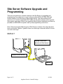
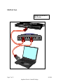
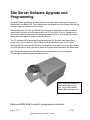
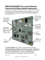
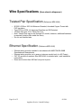
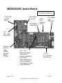
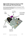
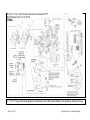
APPLAUSEÔ MEDIA SYSTEM with
Audio/Video Functionality
SERVICE LAUNCH PACKAGE
For ENCOREâ 500/S Series
For Authorized Service Contractors
Page 1 of 15
8/12/09
Applause Service Launch Package
Table of Contents:
Overview
Manuals, Spare Parts and Software
Site Server Software Upgrade & Programming
M06365 Network Connectivity Board
Pulled Wire Specifications
M03565 Audio Board
M09112 PIP
Setting Audio Volume Level
Location of Audio/Connectivity Board Assembly
Block Diagram
Page 2 of 15
8/12/09
Applause Service Launch Package
3
5
6
9
10
11
12
13
14
15
Overview
This launch package covers the APPLAUSE Media System audio/video
functionality release. It is not intended to serve as a replacement for
installation, service, parts manuals or training. A list of reference manuals is
provided. Always ensure you have the most current documentation.
Manuals can be obtained on the Gilbarco Veeder-Root website on GOLDâ
in the Gilbarco Extranet (www.gilbarco.com).
In 2005, SMART MerchandisingÔ was introduced for use with the Encore®
Dispenser Series. SMART Merchandising became the ApplauseÔ Media
System in 2008. This launch package introduces APPLAUSE with
enhanced Audio and Video functionality.
Page 3 of 15
8/12/09
Applause Service Launch Package
Overview (continued)
The Applause release introduces Audio and Video functionality for 10.4–inch Color
Screen. Factory release for Applause audio/video is scheduled for August of 2009. Kits
are available to upgrade existing 10.4-inch Color Screen units in the field.
Upgrade kits for 10.4-inch Color screen units in the field contain:
1. A Network Connectivity Board M06365A002 or A003
2. Audio Boards (1 per side), when needed (Note: some dispensers may already
have audio boards installed)
3. Speakers, when needed (many dispensers already have speakers installed)
4. Associated cables for connectivity
5. Flash Card Software for the Color Screen CRIND
6. Software CD for the Applause Site Server
7. Note: Factory released units will contain audio/video hardware and software
Network Connectivity Board
Audio Boards
Same Assembly
Flash Card
Site Server CD
Page 4 of 15
8/12/09
Applause Service Launch Package
Manual References
·
·
·
·
·
·
·
·
·
·
MDE-4699 Applause Installation and Start-up (Contains installation and startup procedures for
The Applause Media System)
MDE-4703 Applause Media System Color Screen Upgrade Kit (Contains the Audio/Network
Connectivity upgrade along with Flash upgrade for the Color Screen CPU and general Site
Server upgrade procedure – Contact Gilbarco Customer Service for Kit information)
MDE-4301 Applause Media System Quick Reference Card (For Control Center users)
MDE-4349 Applause Media System Control Center User Manual for Merchants/Customers
MDE-4246 Dispenser Upgrade Manual for Network Connectivity (Contains site wiring
options/requirements for Applause)
MDE-3984 Warranty
MDE-4302 Applause Media License Agreement
MDE-4769 Personality Screen Change for Color Screen Instructions
MDE-3804 Encoreâ / Eclipseâ Start Up and Service
Applause Training Course Available: Contact “[email protected]”
Spare Parts and Software Requirements
Part Number
M07543A001
M03565A001
M06365A002
M06365A003
M09112A001
Description
Audio 8 VAC Transformer Board for
(Part of Assembly M07753A00X)
Audio Board (Part of Assembly
M07753A00X Note: This is the same
audio board used on Car Wash Kiosk
and is already a spare part.)
Applause Network Connectivity Board
with Isolation (Part of Assembly
M07753A003/A005) Note: M06365A002
can be used in place of M06365A003)
Applause Network Connectivity Board
with Isolation without DSL (Part of
Assembly M07753A004)
Peripheral Interface PCB (PIP) Board
(Used in Assembly M06481A006)
QTY
QTY
QTY ASC Distributor Distributor
100
100
500
0
1
2
2
4
6
2
4
6
1
2
4
1
2
4
Note: A M06365A002 can be used in place of a M06365A003 if necessary.
M07743K001 (Minimum Version 01.2.07) FLASH Software for 10.4-inch Color
Screen CRIND CPU to support Applause w/ audio/video, and TRIND and EPP.
Site Server CD Software - Minimum Version 30.2.10 to support Applause with
audio/video functionality
Page 5 of 15
8/12/09
Applause Service Launch Package
Site Server Software Upgrade and
Programming
There are two methods to connect a laptop to the Site Server for upgrading and
programming. One method is to use a crossover cable (GVR # Q13850-C06) and
connect directly to the Site Server (See graphic below). The other method (most
common) is to connect a standard CAT 5 cable into the site’s network router or switch
(See graphic next page). Refer to the Applause Media System Installation and Start-up
procedure in MDE-4699 for specific start up and programming instructions.
Note: There are several different types of Site Servers, however, they carry the same
basic functionality. Method 1 graphic shows our oldest type, whereas method 2 shows
our most recent type.
Method 1
Laptop connected
directly to Site Server
Gilbarco Site Server
Laptop
Page 6 of 15
8/12/09
Applause Service Launch Package
Method two
Laptop connected to
Site Router
Page 7 of 15
8/12/09
Applause Service Launch Package
Site Server Software Upgrade and
Programming
The audio/video upgrade kit (contact Gilbarco Customer Service for kit information) is
shipped with a software CD. This software must be loaded onto the Gilbarco Site Server
in order to get the system up and running.
When loading the CD onto the Site Server’s hard drive, make sure to either press the
reset button or power cycle the server while the CD is in the CD drive. A power cycle
can be performed by pressing and holding the power button for 5 seconds, then press
the power button again to power up the Site Server.
The CD software will automatically be placed on the Site Server’s hard drive after a
power cycle. Once complete, the Site Server will automatically open the CD drive.
Remove the CD and close the CD door. Cycle power once again to boot the Site Server
off of the hard drive. Now, you will be ready to program and commission the Site server.
Note: During programming of the Site Server, use “applause” in the Hostname
(for example: storename.applause.gilbarco.com).
Note: There are 4 different
Site Server types in the
field. The “first-released”
Shuttle Box is shown here.
Reference MDE 4699 for specific programming instructions.
Page 8 of 15
8/12/09
Applause Service Launch Package
M06365A002/A003 Forecourt Network
Connectivity Board (Inside dispenser)
The dispensers will need to be upgraded with a Network Connectivity Board. This board
provides high speed Ethernet connectivity inside the pump/dispenser. It receives either
DSL twisted pair or direct Ethernet CAT5E from the store. If Ethernet is used, a jump
jack must be placed in the JP-1 position (must be out for DSL). The A003 Board is
minus the DSL circuitry.
P-3106 Power
Connector to
Color Screen
Interface
Board
P-3621 USB
connection to
Audio Board
Printer Side 1
P-3622 USB
connection to
Audio Board
Printer Side 2
P-3620 Mini
USB to Color
Screen CPU
Board or CCN
to Monochrome
J-3301
Ethernet
From store
J3432
Twisted Pair
From store
JP-1
“Installed” for
Ethernet
The M06365A003 can be used in conjunction with existing
CPE/LRE inside the dispenser (also know as turtles). Therefore, if
the site already has a turtle, then it’s not necessary to replace the
turtle with the M06365A002. Just add the M06365A003.
See Block Diagram on last page for system interconnect.
Page 9 of 15
8/12/09
Applause Service Launch Package
Wire Specifications (from store to dispenser)
Twisted Pair Specification (Reference MDE-4246)
o Q13221-02 Wire- 300 Volt Minimum Stranded, Annealed Copper Tinned with
PVC Insulation
o Type TFFN or NTW, UL Approved Gasoline and Oil Resistant
o 18 AWG Wire with 10-12 Twists Per Foot
o Note: Twisted Pair may be ran through AC conduit, however, additional hardware
is required (Isolation Box inside the store)
o Do not use shielded wire
Ethernet Specification (Reference MDE-4246)
o Ethernet wiring must be installed in accordance with ANSI/TIA/EIA 568B
Standards and Amendments
o Ethernet wiring must be run in spare or intercom conduit only (no AC Power)
o CAT 5E gas and oil resistant. See MDE-4246 for detailed spec., and installation
instructions
o Runs must be less than 280 feet from point to point.
Page 10 of 15
8/12/09
Applause Service Launch Package
M03565A001 Audio Board
Note: Printer USB cables are
routed through Audio Board.
J1561 USB
to CPU
Board
J1562 USB
to Printers
CR-7 Blink =
voice activity
CR-8
On =
intercom
active
To speaker
and
intercom
CR-1
ON = USB
loop active
P1560 to
P302 on
Color
CRIND
Interface
Board
18 VAC
JP-1 / JP-2
Used to increase
hold time for
intercom (default is
8 seconds)
This is the amount
of time allotted for
the customer to talk
to the attendant.
Page 11 of 15
J1563
8 - VAC from
transformer
8/12/09
Applause Service Launch Package
M09112A001 Peripheral Interface PCB
(PIP) Used with 10.4 Color Screen
The PIP is an Interface Board sometimes used with 10.4-inch Color Screen. The PIP
Board is required when both TRIND and EPP exist on a Color Dispenser. It connects to
the Color Screen CPU via USB connection.
The location of the PIP is on the rear side of the Color Screen CPU assembly just below
the USB to LON Interface Board.
P-104
TRIND/
Gateway
P-101 EPP
Keypad/SCR
Side 1
P-311 24 Volt DC
Power from P302
on Color Screen
Interface Board
P-102 EPP
Keypad/SCR
Side 2 P102
P-312 Mini
USB to Color
Screen CPU
Page 12 of 15
8/12/09
Applause Service Launch Package
Setting Audio Volume Level
The Audio level is programmable and accessed through CRIND Diagnostics.
Insert the diagnostics card
Select 1 “Main Menu”
Select 2 “Device Config”
Select 2 “Audio Settings”
Select 1 for side 1 or select 2 for side 2
Set the Audio level by either entering the actual number desired or using the “up” or
“down” soft key functions. A suggested number setting to start with is “93”.
Exit diagnostics (warm start CRIND)
Verify the desired level for the customer.
Page 13 of 15
8/12/09
Applause Service Launch Package
Location of Audio/Network Connectivity
Board Assembly in Dispenser
The Audio/Network Connectivity Board Assembly is located on the top T-Rail inside the
dispenser. It is secured with 3 nuts on the underneath side of the assembly.
Side 2
Side 1
All monochrome to color retrofits and all new color dispensers will include this
audio/video hardware.
The audio board closest to the side is the audio board for that side. In the graphic
above, side 1 of the dispenser is toward the left.
Warranty
Standard warranty applies to the circuit boards installed in the dispenser.
For installed retrofit kits, 1 year on parts.
Reference MDE-3984 for warranty details.
Page 14 of 15
8/12/09
Applause Service Launch Package
A “11 X 17” copy of this block diagram is attached to this TRP and available in the Applause Training Course
Page 15 of 15
Applause Service Launch Package